Joblotron JA-60GSM Bedienungsanleitung
Joblotron
Sicherheitskamera
JA-60GSM
Lesen Sie kostenlos die 📖 deutsche Bedienungsanleitung für Joblotron JA-60GSM (11 Seiten) in der Kategorie Sicherheitskamera. Dieser Bedienungsanleitung war für 34 Personen hilfreich und wurde von 2 Benutzern mit durchschnittlich 4.5 Sternen bewertet
Seite 1/11
JA-60GSM dialer module 1 / 11 MFJ51215
JA-60GSM dialer module
Installation manual
The JA-60GSM dialer is constructed for the JA-60, 63 and 65 alarm control panels. The dialer is used for communication via GSM. An
appropriate GSM provider is chosen according to the inserted SIM card. This Installation manual is intended for the JA-60GSM, version FJ61412.
The GSM module, when installed in the alarm control panel, enables:
Automatic sending of an event’s text messages to up to 8 mobile phones
Dialing of programmed telephone numbers and playing of an audible warning signal
Data transfer to one or two Central Monitoring Stations (CMS)
Remote control and programming of the alarm system via SMS instruction messages from a mobile phone or from Jablotron’s SMS
website
Remote control and programming of the alarm system using a telephone set keypad (mobile or land line)
Remote control of an appliance (heating system etc.) via telephone (mobile or land line)
Phone calls and convenient receiving and sending of SMS messages using an SMS-8010 telephone set (optional accessories; except
GSM kits e.g. JK-05) attached to the dialer module (via the GSM network)
Connection of the intercom SP-01 for communication with the premises
Internet connection using the GPRS data transfer
Programming of the alarm system via ComLink software
Programming and remote supervision of the alarm system via Jablotron’s website www.gsmlink.cz
Multi-language support (only available via keypad instructions)
1 Installation of the dialer
The JA-60GSM dialer can be installed into the telephone
communicator’s position in a JA-60, 63 or 65 control panel (either a
GSM module or a telephone line communicator module can be used in
a control panel – it is not possible to install both simultaneously).
a) Disconnect the control panel’s power supply (both AC and
backup battery). If the control panel has been previously used
before this installation, enter the programming mode before
disconnecting the power supply.
b) We recommend you to disable the SIM card PIN code
protection before you insert it into the dialer. Use a mobile phone
to perform this task (if you have a NOKIA phone, select: Menu,
Settings, Security settings, PIN code request, Off). If you insist on
usage of the PIN, see section 5.1.
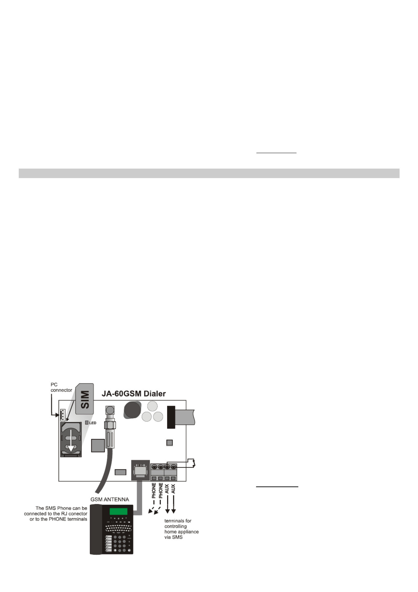
c) Open the SIM card holder (by sliding it in the direction shown in
figure 1) and Insert the SIM card into the holder and close it by
sliding it back. – see figure 1.
d) Attach the dialer into the control panel case and connect its flat
cable to the control panel’s main board.
e) Connect the GSM antenna (never switch the power supply on
without a proper antenna)
f) Connect a SMS-8010 telephone set to the PHONE connector (or to
PHONE terminals) if desired. Only one telephone set can be attached
to the dialer. The PHONE output of the dialer should never be
connected to any other telephone network.
g) If you use the AUX output to control an appliance, connect its
cable to the AUX output terminals (normally open dry contact,
max. 100mA / 60V) – see figure 1.
SY MBO
L
SPAC E
CANCEL MENU NAMES CALLS WRITE READ
1 2 3
456
789
0#
SM S
CA L L
M U T E
FLA SH
RE D IAL
SPEA KE R
figure 1
Note: if your control panel supports programming of the PgX and
PgY outputs for the AUX function (sequences 238 and 239), the
appliance can also be controlled wirelessly from the control panel
by incorporating a UC-216 or UC-222 receiver module into the
system.
h) Reconnect the control panel’s power supply (backup battery
and AC). The system will show a P, (programming mode). The red
LED on the GSM dialer will light permanently (indicating that the
module is establishing a connection with the GSM network). The
LED will switch off after the connection is successfully
established.
If the LED starts flashing, the module was not able to connect to
the GSM network. In this case, switch off the control panel’s power
completely. Remove the SIM card and insert it into a mobile phone
to confirm whether it is possible to connect to the network at this
location. You can also select a desired network manually if options
are available. Ensure that the SIM card does not request a PIN
code (optional use with a PIN code is described in section 5.1).
Once the SIM card works in the mobile phone, reinsert it into the
GSM dialer and repeat step h). If the GSM signal is weak in this
area, change the location of the GSM antenna before you try to
reestablish the connection.
i) Attach the control panel’s cover after the module has connected to
the GSM network (LED switched off).
j) Key in 97701 - to set texts of the communicator to English
language. (English is the default setting, so you can omit this step.)
k) Enter 971 on the alarm system keypad (while in programming
mode) to monitor the GSM signal. The keypad will show a
number from 0 to 9 and it will sound a beep every second
indicating a new measurement. For proper functioning of the dialer
the signal strength should be 3 or higher. Find the best location for
the antenna while measuring the signal strength. To switch the
system back to programming mode press the N key.
l) Without additional programming you can test the user features of
the dialer (phone calls from an attached phone, remote control of
the system via a remote phone, remote control of an appliance
etc.). See the following description.
m) Set telephone numbers for automatic event reporting and the
other selectable features – see part 3.
n) Programming of the GSM dialer is possible by entering
programming sequences via the alarm system’s keypad (while in
programming mode). The most convenient programming method,
however is via a connected PC using ComLink software, or by
using the www.GSMlink.cz website.
JA-60GSM dialer module 2 / 11 MFJ51215
2 User features of the GSM dialer
The installed GSM dialer offers many useful features described in detail
below, or briefly in table 11. A synopsis is available on the user card.
The installer should properly demonstrate the use of the system to the
user after installation.
2.1 Phone calls from the attached telephone set
After the GSM module is connected to the GSM network, an attached
SMS phone can be used to make calls. If you pick up the phone, you will
hear a dial tone. Simply dial the number you want to call (as if you are
dialing from a normal fixed line phone). You can also dial the GSM
communicator’s phone number from another phone, and its attached phone
will ring as a normal land line phone would. If it is necessary to
communicate with CMS the call from the attached phone will be terminated
in 10 minutes.
If there is a busy tone on the attached telephone set, either the line you
are calling is busy, or the GSM communicator is busy with previous
communication at that moment (for example data transfer to the monitoring
station).
You can also use the attached phone keypad to operate the alarm
system. By pressing the # key, you can toggle the keypad from telephone
mode to alarm system control mode.
Note: some telephone sets are sensitive to the GSM radio signal. For
this reason you may hear a characteristic noise in the telephone
receiver when calling. If the noise is disturbing, change the location of
the phone set (try to keep it as far as possible from the GSM dialer
antenna). Usually it is possible to find a suitable location for the phone
with a minimal level of interference.
2.2 Remote control of the alarm system by telephone
A system equipped with a GSM dialer can be remotely controlled. From a
mobile phone there are two possibilities – either by text instructions sent by
SMS or by dialing-in and operating the system via the phone keypad which
will operate in the same way as the alarm system keypad. The dialing-in
method can also be done from an ordinary landline telephone set.
The following description matches the factory default settings of the
communicator. The described features can be greatly modified in the
programming mode – see part 4.
2.3 General rules for remote control by SMS instructions
SMS instructions can be sent from a mobile phone or from an SMS
website.
In SMS, letters are not case-sensitive. Only the basic English alphabet
is accepted by the communicator.
All SMS instruction words must be separated by a space.
If the % is used all previous text will be ignored. The %% symbol when
used in SMS text ends processing – all the following text will be
ignored. It is recommended to use this symbol at the end of the
instruction if the provider sends some additional text after your
message (advertisements etc.).
Warning: if any incoming SMS includes except a valid system
command any extra text which is not separated by % or %%
symbols the command will not be executed
Examples of SMS:
“Hi, this text will be ignored even if I write ME % MO %% Thank
you” – Only MO command will be executed
“Hi, MO” – Command in the SMS will be ignored because there is
an extra text
The default command texts can be customized by an installer (see
4.2.2). For example the instruction AUXON can be changed to
SWITCH ON HEATING etc.
2.4 Arming by SMS (AM xxxx)
The command AM followed with a valid access code can be used to
arm the alarm system. If the system is already armed, the command will
have no effect. SMS text to be sent to the dialer: AM
xxxx
xxxx is a valid alarm system access code (Master or user).
separating character, which can be replaced by a space
Example: Sending AM 1234 will arm the system, which is equivalent to
using code 1234 for arming by keypad
Notes:
According to the default setting, the system confirms command
execution with a corresponding SMS reply
If it is impossible to arm the system – for example if it is in programming
mode, you will be notified about the situation by an SMS reply
If the alarm system is split, the instruction will effect the section which
belongs to the access code used
*
If arming without a code is enabled on the control panel, the AM
command can be used without any access code. In this case the
command performs the same action as the keys F 1 pushed on a
keypad.
2.5 Disarming by SMS (DM xxxx)
Command DM followed with a valid access code will disarm the system.
If the system is already disarmed, the command will have no effect. SMS
text to be sent to the communicator: DM xxxx
xxxx is a valid alarm system access code (Master or user).
separating character, which can be replaced by a space
Example: Sending DM
1234 will disarm the system, which is
equivalent to entering code 1234 on a system keypad.
Notes:
The system confirms disarming with a corresponding SMS reply
If it is impossible to disarm the system – for example it is in programming
mode, you will be notified about the situation by an SMS reply
If the alarm system is split, the instruction will effect the section which
belongs to the access code used
*
* If the alarm system is split and a command is used (AM or DM), the user
code will effect the system the same way as if the code had been entered
from the alarm system keypad – no matter if AM or DM is used (will arm if
the system is disarmed and will disarm if the system is armed).
2.6 Mode request by SMS (MO)
Command MO can be used to read the current alarm system mode.
The dialer will reply with a reporting SMS to the phone which sent the
MO command about status, level of GSM signal, GPRS status, success
of transferring data to the CMSs. SMS text to be sent to the dialer: MO
Example: If the system is armed, it will reply to the MO instruction with
the SMS: Alarm system reports: Control panel status:
Armed,GSM:7,GPRS OK,MS1 NOT,MS2 OK
Note: if you want to protect this command with a password, set your
own instruction text including the password – see section 4.2.2
2.7 Last event request by SMS (ME)
Instruction ME can be used to read the last event recorded in the alarm
system’s memory. The dialer will reply with a reporting SMS. SMS text
to be sent to the dialer: ME
Example: After a fire alarm, it will reply to the ME instruction with the
SMS: Alarm system reports: Last event: Alarm end Control panel Time:
02.06. 19:48
Note: if you want to protect this command with a password, set your
own instruction text including the password – see section 4.2.2.
2.8 Appliance remote control by SMS (AUXON, AUXOFF)
These commands can be used to operate the AUX output (for example
the heating in a house). The dialer confirms command execution with
an SMS reply.
To switch on the AUX output, send SMS text: AUXON
To switch off the AUX output, send SMS text: AUXOFF
Example: to switch on heating send SMS: AUXON
Note: texts of these instructions can be customized and protected with
a password – see section 4.2.2. Outputs PgX and PgY can be
controlled by SMS commands PGON and PGOFF.
2.9 Remote programming of the alarm by SMS (yyyyy PRG seq)
Command PRG can be used to send programming and operating
sequences to the alarm system. It has the same effect, as if the sequences
had been entered on the alarm system keypad. Type the instruction as:
yyyyy
PRG seq,seq,seq,
where
yyyyy is the remote access code; factory default setting is 0000 (4
zeros); the code can be changed, see section 5.4
PRG is the command identification
seq are the programming or operating sequences, consisting of
characters 0 to 9, F, N. There can be more than one sequence in
one SMS. The particular sequences should be separated with a
comma or dot. The number of sequences in one SMS is limited
by the maximum size of the SMS in the GSM network.
separating character, which can be replaced by a space
Example: if the control panel is disarmed and its Installer code is 6060, then
the duration of the alarm can be programmed to 5 minutes and the acoustic
indication of the exit delay can be disabled by sending the following SMS:
0000 PRG F06060,225,330,N
After receiving the SMS command, the control panel will first enter
programming mode (F06060) then sequences 225 and 330 will be
executed and at the end programming mode will be exited (N).

JA-60GSM dialer module 3 / 11 MFJ51215
2.10 Alarm system remote control from a telephone keypad
If you want to operate the alarm system from a phone (mobile or
landline), perform the following:
a) Dial the alarm system phone number. The attached telephone
will ring
b) If the phone is not answered, the system will answer after 25
seconds - indicated by a short beep
c) Enter the remote access code; factory default is 0000 (4 zeros);
to change this code see section 5.4
d) Confirmation sounds indicate the control panel mode: 1 beep =
armed, 2 beeps = disarmed, 3 beeps = programming mode,
Siren sound = alarm.
e) From this moment the telephone keypad will work as the alarm
control panel keypad. The * Key is interpreted as F, the # key
as N.
f) Confirmation sounds indicate the control panel mode: 1 beep =
armed, 2 beeps = disarmed, 3 beeps = programming mode,
Siren sound = alarm.
g) To terminate the connection simply hang up. The connection will
also be terminated if there is no entry within 60 seconds.
Notes:
Remote access from a landline is only possible from a phone
using tone dialing (DTMF)
The reaction of the alarm system to incoming calls can be
modified: see section 5.3
It is impossible to operate the system remotely without a valid
remote access code (if used).
2.11 Appliance remote control via a telephone keypad
If you want to operate outputs PgX or PgY (e.g. a household
appliance) from a phone (mobile or landline), perform the following:
a) Dial the alarm system number. The attached telephone will ring.
b) If the phone is not answered, the system will answer after 25
seconds - indicated with a short beep.
c) Enter the remote user access code; factory default setting is 1111 ;
to change this code see 5.4.
d) The system will confirm validity of the code with a beep.
e) From this moment you can operate the PgX and PgY outputs (if
they are each predefined as phone-controllable) by entering:
*80 to switch off PgX or PgY, or both together,
*81 to switch on PgX or PgY, or both together
(continuously).
f) To terminate the connection simply hang up. The connection will
also be terminated if there is no entry within 60 seconds.
Notes:
Remote access from a land line is only possible from a phone
using tone dialing (DTMF)
The reaction of the system to incoming calls can be modified: see
section 5.3
If the system is not allowed to control without code, the control
sequence must be complete with a user code:
*8[user code]1
*8[user code]0
For this function it is necessary that the alarm system supports F
81 and F 80 sequences
If the dial in function is set (see 3.1.) it is possible to switch ON
the PgX or PgY output for two seconds. The phone call is not
answered therefore it is free of charge.
2.12 Remote voice communication with premises
If the SP-01 intercom is plug-in to the PHONE terminal (it must not be
combined with any phone connected) it is possible to create a one way
(talking or listening) communication from an authorized (stored) phone
numbers (see. 3.1). Procedure:
a) From an authorized phone dial the JA-60GSM phone number.
The SP-01 will ring once and then it will answer the call
b) Potential alarm on the control panel will be terminated
c) You can talk to the premises
d) For switching to the listening mode press 5 on your phone.
For switching back to the talking mode press key 2. Or by
pressing button 1 it is possible to toggle between talking and
listening.
e) Press 0 or hang-up to terminate the call.
Note:
Only a phone with available DTMF can be used.
3 SMS and audible alarm reports
The factory default settings allow the GSM dialer to send SMS
reports and audible warnings when the control panel generates
important information (alarms, arming, etc.). It is only necessary to set
the telephone numbers which the information should be reported to. To
enter these numbers, first enter programming mode.
If you prefer to report more or different events than the factory
default provides, see section 4.
3.1 Telephone numbers entering
The dialer has 8 telephone number memories. Each memory has
assigned particular SMS reports and/or audible warnings according to the
default setting – see table 1.1. By entering a telephone number in to a
particular memory location you are selecting what will be reported to this
number:
7t xxx...x F0
Where t is a memory location from 1 to 8
xxx...x is a telephone number (max. 20 digits),
enter F9 before the number, if you need the + prefix for international
calls. To use an attached SMS telephone set, enter code 001 instead of
the telephone number. To authorize a phone number for communication
with premises via the SP-01 intercom set F8 (#) at the end of the phone
number or F7 (*) for dial-in function (see 2.11.).
To disable reporting to a particular number, delete this number
memory by entering:
7tF0
where t is a memory from 1 to 8
Report testing:
If you wish to report any alarm, arming and disarming by SMS followed
by the notifying call and your mobile phone number is 123456789, then
enter 75123456789F0 (while the control panel is in programming mode).
Then exit programming mode by pushing the key. Now you can arm N
the system and your mobile phone will receive a reporting SMS.
3.2 Installation name in SMS reports
Each reporting SMS message starts with: “Alarm system reports:”. You
can change this default title text by sending the dialer the following text
programming SMS:
yyyyy
TXT
700,text
where
yyyyy is the remote access code; factory default is 0000 (4
zeros); the code can be changed, see 5.4
TXT is the text programming command
700 is the index number on the system text table
corresponding to the installation name
, comma (separator)
text is your own new installation name. A comma or dot
cannot be used in the text. A blank space inside the
text is a valid character (the dialer ignores spaces
before the separator)
separating character, which can be replaced by a space
Example: If the default code is in the dialer, then sending SMS:
0000 TXT 700, Mr. Diamond’s jewelry shop reports:
to the dialer will change the installation name to the above text.
Note: all the SMS texts stored in the dialer can be changed in a similar
way, see section 4.2 for details.
Produktspezifikationen
| Marke: | Joblotron |
| Kategorie: | Sicherheitskamera |
| Modell: | JA-60GSM |
Brauchst du Hilfe?
Wenn Sie Hilfe mit Joblotron JA-60GSM benötigen, stellen Sie unten eine Frage und andere Benutzer werden Ihnen antworten
Bedienungsanleitung Sicherheitskamera Joblotron

10 Juni 2023
10 Juni 2023
10 Juni 2023
10 Juni 2023
10 Juni 2023
10 Juni 2023
10 Juni 2023
10 Juni 2023
10 Juni 2023
10 Juni 2023
Bedienungsanleitung Sicherheitskamera
- Sicherheitskamera Samsung
- Sicherheitskamera Anker
- Sicherheitskamera Approx
- Sicherheitskamera Sanyo
- Sicherheitskamera Exibel
- Sicherheitskamera Gembird
- Sicherheitskamera Hama
- Sicherheitskamera LogiLink
- Sicherheitskamera Logitech
- Sicherheitskamera Manhattan
- Sicherheitskamera Nedis
- Sicherheitskamera Sony
- Sicherheitskamera Panasonic
- Sicherheitskamera Clas Ohlson
- Sicherheitskamera Profile
- Sicherheitskamera LG
- Sicherheitskamera Bosch
- Sicherheitskamera Canon
- Sicherheitskamera TechniSat
- Sicherheitskamera Allnet
- Sicherheitskamera Eminent
- Sicherheitskamera Linksys
- Sicherheitskamera Maginon
- Sicherheitskamera Netgear
- Sicherheitskamera Schwaiger
- Sicherheitskamera Technaxx
- Sicherheitskamera Alecto
- Sicherheitskamera Denver
- Sicherheitskamera EMOS
- Sicherheitskamera Gira
- Sicherheitskamera König
- Sicherheitskamera Thomson
- Sicherheitskamera Blaupunkt
- Sicherheitskamera Braun
- Sicherheitskamera Grundig
- Sicherheitskamera Trebs
- Sicherheitskamera Pyle
- Sicherheitskamera Mitsubishi
- Sicherheitskamera Fortinet
- Sicherheitskamera Caliber
- Sicherheitskamera I-Onik
- Sicherheitskamera Jay-Tech
- Sicherheitskamera JVC
- Sicherheitskamera Motorola
- Sicherheitskamera Xiaomi
- Sicherheitskamera Abus
- Sicherheitskamera Avidsen
- Sicherheitskamera Elro
- Sicherheitskamera EZVIZ
- Sicherheitskamera Imou
- Sicherheitskamera INSTAR
- Sicherheitskamera Megasat
- Sicherheitskamera Olympia
- Sicherheitskamera Smartwares
- Sicherheitskamera Switel
- Sicherheitskamera Yale
- Sicherheitskamera Ferguson
- Sicherheitskamera Strong
- Sicherheitskamera Toshiba
- Sicherheitskamera E-Bench
- Sicherheitskamera Withings
- Sicherheitskamera Lindy
- Sicherheitskamera Waeco
- Sicherheitskamera Burg Wächter
- Sicherheitskamera Marmitek
- Sicherheitskamera Marshall
- Sicherheitskamera Honeywell
- Sicherheitskamera B/R/K
- Sicherheitskamera Marshall Electronics
- Sicherheitskamera TRENDnet
- Sicherheitskamera MINOX
- Sicherheitskamera Ricoh
- Sicherheitskamera Western Digital
- Sicherheitskamera RADEMACHER
- Sicherheitskamera First Alert
- Sicherheitskamera AVerMedia
- Sicherheitskamera Zebra
- Sicherheitskamera TP-Link
- Sicherheitskamera Humax
- Sicherheitskamera Flamingo
- Sicherheitskamera Kerbl
- Sicherheitskamera Vtech
- Sicherheitskamera Kodak
- Sicherheitskamera Broan
- Sicherheitskamera IGet
- Sicherheitskamera Adj
- Sicherheitskamera Netatmo
- Sicherheitskamera Xavax
- Sicherheitskamera InFocus
- Sicherheitskamera Overmax
- Sicherheitskamera Monacor
- Sicherheitskamera JUNG
- Sicherheitskamera Ednet
- Sicherheitskamera AG Neovo
- Sicherheitskamera Nest
- Sicherheitskamera Edimax
- Sicherheitskamera Aritech
- Sicherheitskamera Uniden
- Sicherheitskamera M-e
- Sicherheitskamera Siedle
- Sicherheitskamera Elmo
- Sicherheitskamera Conceptronic
- Sicherheitskamera D-Link
- Sicherheitskamera Eufy
- Sicherheitskamera Stabo
- Sicherheitskamera Friedland
- Sicherheitskamera EVOLVEO
- Sicherheitskamera ION
- Sicherheitskamera SPC
- Sicherheitskamera Ring
- Sicherheitskamera Digitus
- Sicherheitskamera SereneLife
- Sicherheitskamera Swann
- Sicherheitskamera Vitek
- Sicherheitskamera DataVideo
- Sicherheitskamera LevelOne
- Sicherheitskamera APC
- Sicherheitskamera Cisco
- Sicherheitskamera Grandstream
- Sicherheitskamera EVE
- Sicherheitskamera EasyMaxx
- Sicherheitskamera Tenda
- Sicherheitskamera Boss
- Sicherheitskamera Swisstone
- Sicherheitskamera Foscam
- Sicherheitskamera Ubiquiti Networks
- Sicherheitskamera Extech
- Sicherheitskamera Kramer
- Sicherheitskamera Intellinet
- Sicherheitskamera Reolink
- Sicherheitskamera Hikvision
- Sicherheitskamera FLIR
- Sicherheitskamera Arlo
- Sicherheitskamera Nexxt
- Sicherheitskamera Planet
- Sicherheitskamera EnGenius
- Sicherheitskamera Lorex
- Sicherheitskamera Google
- Sicherheitskamera Comtrend
- Sicherheitskamera Somfy
- Sicherheitskamera Aldi
- Sicherheitskamera Dedicated Micros
- Sicherheitskamera EverFocus
- Sicherheitskamera Ganz
- Sicherheitskamera GeoVision
- Sicherheitskamera Indexa
- Sicherheitskamera Raymarine
- Sicherheitskamera Revo
- Sicherheitskamera SecurityMan
- Sicherheitskamera Sitecom
- Sicherheitskamera Steren
- Sicherheitskamera Vivotek
- Sicherheitskamera Wanscam
- Sicherheitskamera Y-cam
- Sicherheitskamera ACTi
- Sicherheitskamera Epcom
- Sicherheitskamera ZKTeco
- Sicherheitskamera Moxa
- Sicherheitskamera Sonoff
- Sicherheitskamera AirLive
- Sicherheitskamera Mobotix
- Sicherheitskamera Hollyland
- Sicherheitskamera Avanti
- Sicherheitskamera Dahua Technology
- Sicherheitskamera Speco Technologies
- Sicherheitskamera Aluratek
- Sicherheitskamera 3xLOGIC
- Sicherheitskamera Inovonics
- Sicherheitskamera Atlantis Land
- Sicherheitskamera Pentatech
- Sicherheitskamera Surveon
- Sicherheitskamera Avigilon
- Sicherheitskamera Hanwha
- Sicherheitskamera Lupus Electronics
- Sicherheitskamera Lanberg
- Sicherheitskamera Verint
- Sicherheitskamera Axis
- Sicherheitskamera EtiamPro
- Sicherheitskamera Advantech
- Sicherheitskamera Wisenet
- Sicherheitskamera Chacon
- Sicherheitskamera Alula
- Sicherheitskamera KT&C
- Sicherheitskamera EKO
- Sicherheitskamera IOIO
- Sicherheitskamera KJB Security Products
- Sicherheitskamera BZBGear
- Sicherheitskamera Ansel
- Sicherheitskamera Crestron
- Sicherheitskamera Aigis
- Sicherheitskamera Pelco
- Sicherheitskamera ORNO
- Sicherheitskamera Atlona
- Sicherheitskamera Linear PRO Access
- Sicherheitskamera Laxihub
- Sicherheitskamera Aqara
- Sicherheitskamera Tecno
- Sicherheitskamera Lutec
- Sicherheitskamera Brinno
- Sicherheitskamera Night Owl
- Sicherheitskamera Exacq
- Sicherheitskamera UniView
- Sicherheitskamera Alfatron
- Sicherheitskamera BLOW
- Sicherheitskamera Digimerge
- Sicherheitskamera Milestone Systems
- Sicherheitskamera Inkovideo
- Sicherheitskamera Ecobee
- Sicherheitskamera Infortrend
- Sicherheitskamera Promise Technology
- Sicherheitskamera VideoComm
- Sicherheitskamera Feelworld
- Sicherheitskamera Kwikset
- Sicherheitskamera Kguard
- Sicherheitskamera HiLook
- Sicherheitskamera Mach Power
- Sicherheitskamera Digital Watchdog
- Sicherheitskamera Ernitec
- Sicherheitskamera Channel Vision
- Sicherheitskamera Ikegami
- Sicherheitskamera Gewiss
- Sicherheitskamera Arenti
- Sicherheitskamera Qoltec
- Sicherheitskamera Weldex
- Sicherheitskamera Costar
- Sicherheitskamera American Dynamics
- Sicherheitskamera Sentry360
- Sicherheitskamera Seco-Larm
- Sicherheitskamera ALC
- Sicherheitskamera Spyclops
- Sicherheitskamera Hawking Technologies
- Sicherheitskamera IDIS
- Sicherheitskamera EFB Elektronik
- Sicherheitskamera I3International
- Sicherheitskamera B & S Technology
- Sicherheitskamera Astak
- Sicherheitskamera Qian
- Sicherheitskamera Qolsys
- Sicherheitskamera Wasserstein
- Sicherheitskamera Turing
- Sicherheitskamera Epiphan
Neueste Bedienungsanleitung für -Kategorien-
4 Dezember 2024
4 Dezember 2024
4 Dezember 2024
4 Dezember 2024
4 Dezember 2024
3 Dezember 2024
3 Dezember 2024

2 Dezember 2024
14 August 2024
11 August 2024