LevelOne PPM-1000 Bedienungsanleitung
Lesen Sie kostenlos die 📖 deutsche Bedienungsanleitung für LevelOne PPM-1000 (3 Seiten) in der Kategorie Kabel für PCs und Peripheriegeräte. Dieser Bedienungsanleitung war für 15 Personen hilfreich und wurde von 2 Benutzern mit durchschnittlich 4.5 Sternen bewertet
Seite 1/3

LevelOne
User Manual
PPM-1000
PoE Power Measurement
On-site PoE Power Measurement
PPM- OVERVIEW 1000
PPM- a handheld tester for the applications of 1000 is
Power over Ethernet (PoE). It performs -site on
measurement of the running voltage and supplying power
at the end of Ethernet cable terminal in any length for PoE
PSE/PD devices which complies with IEEE802.3af.
PPM- provides for field engineer a convenient on-site 1000
tester with compact size to verify PoE, measure the voltage,
and examine the maximum power from PSE to PD at the
end point of the Ethernet cable.
Powered by replaceable and rechargeable battery, the
portable - allows the technical personnel to test PPM 1000
terminal for PD in the fields .
With 3- git LED display, it shows the PoE status and the di
maximum power available from . Pass/Fail LED PSE
indicators may inform technician the results instantly.
With built-in Terminal Block connectors, - is able PPM 1000
to clamp and hold the bare wires of network cable for test
before clamping to the RJ-45 connector. - is in PPM 1000
truly the best handy tool for the installation of PoE PD
devices. With the tester, it shall successfully guarantee
the PoE power provision to PD devices.
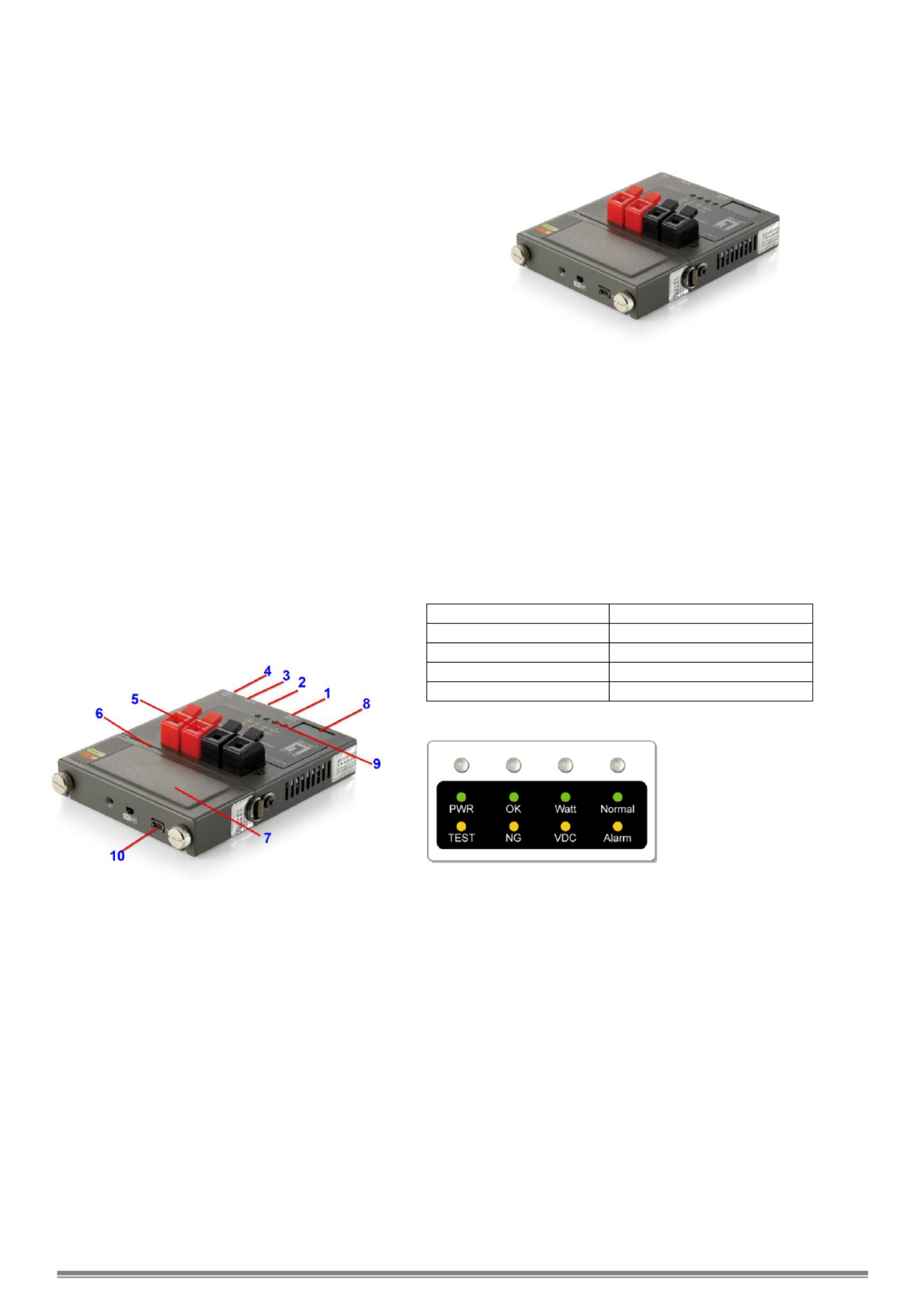
Mechanical Description
LED Indicators
Buttons and LED Indicators
Start/Set(-) Button
:
:
:
::
Set the desire maximum power (Watt) for test:
Push and hold Start/Set(- button for 3 seconds to enter for )
configuration of maximum power limit It confirms with . a
beep sound and the 3-digit LED display start blinking.
Press the Start/Set(-) or Start/Set(- buttons to set the )
desired power limit Then, push and hold Start/Set(- button )
for 3 seconds to exit the configuration stage.
Press once to start measurement and press again to finish
the test procedure.
Display/Set(+) Button
Select options for display the Voltage, Power ing
Consumption Limit and Temperature.
While LED PWR/TEST is in during testing torange , he
3-digit Display shows the instantaneous power s. value
While LED PWR/TEST is in t 3-digit display will green, he
show the final result of power measurement.
Note that if the LED OK/NG is in , it indicates the green OK
power from PSE is able to provide the desired power
consumption limit; else LED OK/NG will be in orange NG,
indicating the power is not enough for the PD requirement.
Display/Set(+) Button
Console Port (for upgrade)
Network RJ45 UTP Port
Start/Set(-) Button
Power Probing Terminal
USB Power Port
External Battery Pack
3-Digit Display
LED Indicators
USB Port (charge battery)
Console Port
Connect PPM- to PC by console cable. Run HyperTerminal 1000 in
Windows at 38400 bps (Baud Rate) to connect and open the default
settings. Press Ctrl+C to enter main menu. Select A to check
firmware version B to update firmware with using X modem or
protocol.

PWR/TEST LED
When test is started, PWR/TEST LED is blinking orange
When test is finished, PWR/TEST LED keeps orange
When test is finished ready for next test, PWR/TEST LED
keeps green
WATT/VDC LED
When LED is in green, the 3-digit LED display shows the
PoE power in unit of Watt.
When LED is in orange, the 3-digit LED display shows the
PoE DC voltage.
When LED is off and Normal/Alarm LED is , the green
3-digit LED display shows the value of temperature.
OK/NG LED
When LED is in green, it indicates the power from PSE is
able to provide the desire maximum power to PD.
When LED is in orange, it indicates the power is not
enough to support the desire maximum power to PD.
When LE is in , the measurement is D blinking orange
failed and the Current is too high (over 2A).
When LED is off and Normal/Alarm LED i , the s in orange
measurement is failed and the device is over-temperature
(over ). 100℃
Normal/Alarm LED
When LED is in green, the LED digits display shows the
value of temperature
When LED is in orange, the device is over-temperature
(over 100℃).
Measurement Procedures
Hardware connection
Screw tightly the battery pack and connect the cable
as the illustration. Switch power on at the bottom.
For cable bare wires, these can be clamped into
Power Probing Terminal directly for Mode A (Power via
Pin 1, 2, 3, 6) or Mode B (Power via Pin 4, 5, 7, 8) of
IEEE802.3af standard.
Note: Network cable can not be connected to UTP port
and Power Probing Terminal simultaneously.
Operation Procedure
1. To set desire maximum power from PS to PD for test. E
Push and hold Start/Set(-) Button for 3 seconds to enter for configuration of maximum power limit It confirms with a beep .
sound and the 3-dig LED display start blinking. Press the it Start/Set(-) Start/Set(-) or buttons to set the desired power limit
Then, push and hold Start/Set(- button for 3 seconds to exit the configuration stag) e.
2. Press Start/Set(-) Button to start power measurement st. te
The will start , and the 3-digit LED display will show the changing power measurement. After PWR/TEST LED orange blinking
the test is done, i the is , it indicates that the power from PSE could support the desire maximum powerf OK/NG LED green ON .
If the OK/NG LED is , it indicates that the power from PSE could support the desire maximum power. orange ON NOT
Note that if - is over 50 the test will be prohibited Wait till it cools down for normal start. Once it starts testing, the PPM 1000 °C, .
tolerated temperature will be up to 100 °C.
3. Press to show the real-time value or measurement resultDisplay/Set(+) Button s.
Show value of measurement results while the is after test. PWR/TEST LED orange
Press once to show the value of power measurement when the Display/Set(+) Button WATT/VDC LED is . green
Press again to show the value of DC voltage when the Display/Set(+) Button WATT/VDC LED is . orange
Press again to show the device temperature when the is Display/Set(+) Button Normal/Alarm LED green.
Show real-time value (by pressing Start/Set(-) Button PWR/TEST LED) while the is green.
Press once to show the value of power measurement when the Display/Set(+) Button WATT/VDC LED is green.
Press again to show the value of DC voltage when tDisplay/Set(+) Button he WATT/VDC LED is orange.
Press again to show the device temperature when the is . Display/Set(+) Button Normal/Alarm LED green
4. Alarm notification
When Normal/Alarm LED , it indicates that PPM- is over-temperature (over Please stop the is orange ON 1000 100℃).
measurement until e device i cool down below 50 . th s °C
Specifications
Detection Range:
Watt: 0~96W
Voltage: ~60V (Over V is 24 40
required initially.)
Current: 0~2A
Power:
External Battery Pack
Provide 7 hours of standby time, shorter if
operations k going. eep
Overload Protection:
Operation Temp:
Humility:
Polyswitch over current protection
- ~ 20°C 50°C
0% ~ 85% RH
Battery
Pack:
Li-Ion, 2,400 mAh, 3.7 V,
Charged by USB cable
Charge Time: 3~4 hours
Produktspezifikationen
| Marke: | LevelOne |
| Kategorie: | Kabel für PCs und Peripheriegeräte |
| Modell: | PPM-1000 |
Brauchst du Hilfe?
Wenn Sie Hilfe mit LevelOne PPM-1000 benötigen, stellen Sie unten eine Frage und andere Benutzer werden Ihnen antworten
Bedienungsanleitung Kabel für PCs und Peripheriegeräte LevelOne

2 August 2024
28 Juli 2024
Bedienungsanleitung Kabel für PCs und Peripheriegeräte
- Kabel für PCs und Peripheriegeräte Apple
- Kabel für PCs und Peripheriegeräte Approx
- Kabel für PCs und Peripheriegeräte Belkin
- Kabel für PCs und Peripheriegeräte Corsair
- Kabel für PCs und Peripheriegeräte Gembird
- Kabel für PCs und Peripheriegeräte Genius
- Kabel für PCs und Peripheriegeräte Hama
- Kabel für PCs und Peripheriegeräte HP
- Kabel für PCs und Peripheriegeräte LogiLink
- Kabel für PCs und Peripheriegeräte Manhattan
- Kabel für PCs und Peripheriegeräte Nedis
- Kabel für PCs und Peripheriegeräte Sony
- Kabel für PCs und Peripheriegeräte Targus
- Kabel für PCs und Peripheriegeräte Trust
- Kabel für PCs und Peripheriegeräte Brennenstuhl
- Kabel für PCs und Peripheriegeräte Laserliner
- Kabel für PCs und Peripheriegeräte Eminent
- Kabel für PCs und Peripheriegeräte Netgear
- Kabel für PCs und Peripheriegeräte EMOS
- Kabel für PCs und Peripheriegeräte König
- Kabel für PCs und Peripheriegeräte Blaupunkt
- Kabel für PCs und Peripheriegeräte Kenwood
- Kabel für PCs und Peripheriegeräte Worx
- Kabel für PCs und Peripheriegeräte Pyle
- Kabel für PCs und Peripheriegeräte Sennheiser
- Kabel für PCs und Peripheriegeräte Shure
- Kabel für PCs und Peripheriegeräte Goobay
- Kabel für PCs und Peripheriegeräte Icy Box
- Kabel für PCs und Peripheriegeräte Lindy
- Kabel für PCs und Peripheriegeräte Cabstone
- Kabel für PCs und Peripheriegeräte Lenovo
- Kabel für PCs und Peripheriegeräte Tripp Lite
- Kabel für PCs und Peripheriegeräte Marmitek
- Kabel für PCs und Peripheriegeräte Honeywell
- Kabel für PCs und Peripheriegeräte TP-Link
- Kabel für PCs und Peripheriegeräte Black Box
- Kabel für PCs und Peripheriegeräte 4smarts
- Kabel für PCs und Peripheriegeräte Xtorm
- Kabel für PCs und Peripheriegeräte Techly
- Kabel für PCs und Peripheriegeräte Vogel's
- Kabel für PCs und Peripheriegeräte Vision
- Kabel für PCs und Peripheriegeräte Monacor
- Kabel für PCs und Peripheriegeräte Platinum
- Kabel für PCs und Peripheriegeräte Kogan
- Kabel für PCs und Peripheriegeräte Audiovox
- Kabel für PCs und Peripheriegeräte HQ
- Kabel für PCs und Peripheriegeräte Sanus
- Kabel für PCs und Peripheriegeräte NewStar
- Kabel für PCs und Peripheriegeräte Digitus
- Kabel für PCs und Peripheriegeräte Reflecta
- Kabel für PCs und Peripheriegeräte DataVideo
- Kabel für PCs und Peripheriegeräte APC
- Kabel für PCs und Peripheriegeräte Akasa
- Kabel für PCs und Peripheriegeräte Cisco
- Kabel für PCs und Peripheriegeräte Greenlee
- Kabel für PCs und Peripheriegeräte CyberPower
- Kabel für PCs und Peripheriegeräte Deltaco
- Kabel für PCs und Peripheriegeräte Fresh 'n Rebel
- Kabel für PCs und Peripheriegeräte Cablexpert
- Kabel für PCs und Peripheriegeräte Kramer
- Kabel für PCs und Peripheriegeräte Intellinet
- Kabel für PCs und Peripheriegeräte RCA
- Kabel für PCs und Peripheriegeräte Eaton
- Kabel für PCs und Peripheriegeräte Kicker
- Kabel für PCs und Peripheriegeräte Speed-Link
- Kabel für PCs und Peripheriegeräte Fluke
- Kabel für PCs und Peripheriegeräte McIntosh
- Kabel für PCs und Peripheriegeräte JL Audio
- Kabel für PCs und Peripheriegeräte Vorago
- Kabel für PCs und Peripheriegeräte Simplified MFG
- Kabel für PCs und Peripheriegeräte Elgato
- Kabel für PCs und Peripheriegeräte Duronic
- Kabel für PCs und Peripheriegeräte GeoVision
- Kabel für PCs und Peripheriegeräte Infinity
- Kabel für PCs und Peripheriegeräte Media-tech
- Kabel für PCs und Peripheriegeräte Nordval
- Kabel für PCs und Peripheriegeräte Rittal
- Kabel für PCs und Peripheriegeräte Steren
- Kabel für PCs und Peripheriegeräte AMX
- Kabel für PCs und Peripheriegeräte Adder
- Kabel für PCs und Peripheriegeräte Chief
- Kabel für PCs und Peripheriegeräte Siig
- Kabel für PCs und Peripheriegeräte AudioControl
- Kabel für PCs und Peripheriegeräte RGBlink
- Kabel für PCs und Peripheriegeräte Iogear
- Kabel für PCs und Peripheriegeräte StarTech.com
- Kabel für PCs und Peripheriegeräte Panduit
- Kabel für PCs und Peripheriegeräte Gefen
- Kabel für PCs und Peripheriegeräte Aluratek
- Kabel für PCs und Peripheriegeräte Legrand
- Kabel für PCs und Peripheriegeräte J5 Create
- Kabel für PCs und Peripheriegeräte ASSMANN Electronic
- Kabel für PCs und Peripheriegeräte Arris
- Kabel für PCs und Peripheriegeräte ATen
- Kabel für PCs und Peripheriegeräte Pyramid
- Kabel für PCs und Peripheriegeräte Wentronic
- Kabel für PCs und Peripheriegeräte Hobbes
- Kabel für PCs und Peripheriegeräte On-Q
- Kabel für PCs und Peripheriegeräte Crestron
- Kabel für PCs und Peripheriegeräte Argus
- Kabel für PCs und Peripheriegeräte Extron
- Kabel für PCs und Peripheriegeräte V7
- Kabel für PCs und Peripheriegeräte Atlona
- Kabel für PCs und Peripheriegeräte Advance Acoustic
- Kabel für PCs und Peripheriegeräte Rocstor
- Kabel für PCs und Peripheriegeräte Apricorn
- Kabel für PCs und Peripheriegeräte Equip
- Kabel für PCs und Peripheriegeräte Raidsonic
- Kabel für PCs und Peripheriegeräte Satechi
- Kabel für PCs und Peripheriegeräte IPort
- Kabel für PCs und Peripheriegeräte AudioQuest
- Kabel für PCs und Peripheriegeräte Roline
- Kabel für PCs und Peripheriegeräte Hamlet
- Kabel für PCs und Peripheriegeräte Kurth Electronic
- Kabel für PCs und Peripheriegeräte Hall Research
- Kabel für PCs und Peripheriegeräte CommScope
- Kabel für PCs und Peripheriegeräte Mach Power
- Kabel für PCs und Peripheriegeräte Inno-Hit
- Kabel für PCs und Peripheriegeräte Tempo
- Kabel für PCs und Peripheriegeräte Qoltec
- Kabel für PCs und Peripheriegeräte EXSYS
- Kabel für PCs und Peripheriegeräte ICC
- Kabel für PCs und Peripheriegeräte ISimple
- Kabel für PCs und Peripheriegeräte C2G
- Kabel für PCs und Peripheriegeräte EK Water Blocks
- Kabel für PCs und Peripheriegeräte Axagon
- Kabel für PCs und Peripheriegeräte Sabrent
- Kabel für PCs und Peripheriegeräte Micro Connect
- Kabel für PCs und Peripheriegeräte IC Intracom
- Kabel für PCs und Peripheriegeräte Cables Direct
- Kabel für PCs und Peripheriegeräte Sonero
- Kabel für PCs und Peripheriegeräte Nexibo
- Kabel für PCs und Peripheriegeräte Sunix
- Kabel für PCs und Peripheriegeräte Comprehensive
- Kabel für PCs und Peripheriegeräte PureLink
- Kabel für PCs und Peripheriegeräte Luxul
Neueste Bedienungsanleitung für -Kategorien-
8 Oktober 2024
1 Oktober 2024
1 Oktober 2024
1 Oktober 2024
30 September 2024

29 September 2024
24 September 2024
23 September 2024
21 September 2024
21 September 2024