HP Aruba Unified AP-515 Bedienungsanleitung
HP
Zugangspunkt
Aruba Unified AP-515
Lesen Sie kostenlos die 📖 deutsche Bedienungsanleitung für HP Aruba Unified AP-515 (15 Seiten) in der Kategorie Zugangspunkt. Dieser Bedienungsanleitung war für 64 Personen hilfreich und wurde von 2 Benutzern mit durchschnittlich 4.5 Sternen bewertet
Seite 1/15

Aruba 510 Series Campus Access Points
Installation Guide
Rev05 | December 2019 1
The Aruba 510 Series Campus Access Points (AP-514 and AP-515) are high-performance, multi-radio wireless
devices that can be deployed in either controller-based (ArubaOS) or controllerless (Aruba Instant) network
environments. These access points deliver high performance concurrent 2.4 GHz and 5 GHz 802.11ax Wi-Fi
functionality with MIMO radios (2x2 in 2.4 GHz, 4x4 in 5 GHz), while also supporting legacy 802.11a/b/g/n/ac
wireless services.
Ethernet ports located on the back of this access points are used to connect the device to the wired networking
infrastructure and to provide (802.3at class 4) PoE power to the device.
In addition to both Wi-Fi radios, these APs also incorporate a Bluetooth Low Energy (BLE) and Zigbee radio,
supporting a variety of use-cases and services, such as locationing and IoT.
A mount kit (sold separately) is needed to mount the AP. Make sure to purchase the correct mount kit for the
intended deployment of the AP.
Package Contents
Aruba 510 Series Campus Access Point (with a pre-installed mount bracket)
Hardware Overview
The following sections outline the hardware components of the 510 Series access points.
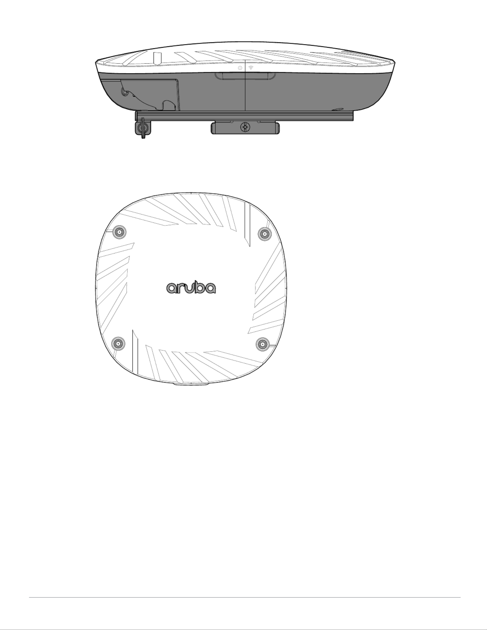
Figure 1 AP-515 Front View
The AP mount bracket attaches to a variety of mount kits (sold separately).
Inform your supplier if there are any incorrect, missing, or damaged parts. If possible, retain the carton, including
the original packing materials. Use these materials to repack and return the unit to the supplier if needed.
2Aruba 510 Series Campus Access Points | Installation Guide
Figure 2 LEDs (AP-515 shown)
Figure 3 AP-514 Front View
External Antenna Connectors
The AP-514 access points are equipped with four external antenna connectors located on the front
corners of the access point (see Figure 3). Antenna ports A0 and A1 (corresponding with radio chains 0
and 1), are used for both radios and bands (RF signals are diplexed), while antenna ports A2 and A3
(corresponding with radio chains 2 and 3) are used for the 5 GHz radio only.
A0
A1
A2
A3

Aruba 510 Series Campus Access Points | Installation Guide 3
LEDs
The LED displays located on the front panel of the access point indicate the following functions:
System Status
The System Status LED indicates the operating condition of the access point, See Table 1.
Table 1 System Status LED
Radio Status
The Radio Status LED indicates the operating mode of the access point’s radios. See Table 2.
Table 2 Radio Status LEDs
!
!
!
!!
External antennas for this device must be installed by an Aruba Certified Mobility Professional (ACMP) or other
Aruba-certified technician, using manufacturer-approved antennas only.
The Equivalent Isotropically Radiated Power (EIRP) levels for all external antenna devices must not exceed the
regulatory limit set by the host country/domain.
Installers are required to record the antenna gain for this device in the system management software. A list of
approved antennas can be found at: http://www.arubanetworks.com/assets/og/OG_AP-510Series.pdf.
Les antennes externes pour cet appareil doivent être installées par un professionnel de la mobilité certifié Aruba
(ACMP) ou un autre technicien certifié Aruba, en utilisant uniquement des antennes approuvées par le fabricant.
Les niveaux équivalents de puissance à rayonnement isotrope (EIRP) pour tous les périphériques d'antenne
externe ne doivent pas dépasser la limite réglementaire définie par le pays hôte / domaine.
Les installateurs doivent enregistrer le gain d'antenne pour cet appareil dans le logiciel de gestion du système.
Une liste d'antennes approuvées peut être trouvée à http://www.arubanetworks.com/assets/og/OG_AP-
510Series.pdf.
Color/State Meaning
Off Device Powered off
Green- solid Device ready, fully functional, no network restrictions
Green- blinking 1
1. Blinking: one second on, one second off, 2 seconds cycle.
Device booting, not ready
Green- flashing 2
2. Flashing: mostly on, fraction of a second off, 2 seconds cycle.
Device ready, fully functional, either uplink negotiated in sub-optimal speed
(<1Gbps)
Amber- solid Device ready, restricted power mode (limited PoE power available, or IPM
restrictions applied), no network restrictions
Amber- flashing Device ready, restricted power mode (limited PoE power available, or IPM
restrictions applied), uplink negotiated in sub-optimal speed
Red System error condition - Immediate attention required
Color/State Meaning
Off Device powered off, or both radios disabled
Green- solid Both radios enabled in access mode
Produktspezifikationen
| Marke: | HP |
| Kategorie: | Zugangspunkt |
| Modell: | Aruba Unified AP-515 |
Brauchst du Hilfe?
Wenn Sie Hilfe mit HP Aruba Unified AP-515 benötigen, stellen Sie unten eine Frage und andere Benutzer werden Ihnen antworten
Bedienungsanleitung Zugangspunkt HP

30 Juni 2024
28 Juni 2024
28 Juni 2024
28 Mai 2024
8 September 2023
8 September 2023
8 September 2023
8 September 2023
12 Oktober 2022
Bedienungsanleitung Zugangspunkt
- Zugangspunkt Asus
- Zugangspunkt Macally
- Zugangspunkt ZyXEL
- Zugangspunkt Bosch
- Zugangspunkt Buffalo
- Zugangspunkt Allnet
- Zugangspunkt Devolo
- Zugangspunkt Eminent
- Zugangspunkt Linksys
- Zugangspunkt Netgear
- Zugangspunkt Renkforce
- Zugangspunkt Fortinet
- Zugangspunkt Netis
- Zugangspunkt Aruba
- Zugangspunkt Lindy
- Zugangspunkt Dell
- Zugangspunkt Mercusys
- Zugangspunkt Honeywell
- Zugangspunkt TRENDnet
- Zugangspunkt AVM
- Zugangspunkt Zebra
- Zugangspunkt TP-Link
- Zugangspunkt Black Box
- Zugangspunkt Techly
- Zugangspunkt Hercules
- Zugangspunkt Huawei
- Zugangspunkt Edimax
- Zugangspunkt DrayTek
- Zugangspunkt Totolink
- Zugangspunkt D-Link
- Zugangspunkt Digitus
- Zugangspunkt DataVideo
- Zugangspunkt Lancom
- Zugangspunkt LevelOne
- Zugangspunkt Cisco
- Zugangspunkt Grandstream
- Zugangspunkt Tenda
- Zugangspunkt Ubiquiti Networks
- Zugangspunkt Intellinet
- Zugangspunkt Bintec-elmeg
- Zugangspunkt Planet
- Zugangspunkt EnGenius
- Zugangspunkt Mikrotik
- Zugangspunkt Moog
- Zugangspunkt Homematic IP
- Zugangspunkt EQ3
- Zugangspunkt Comtrend
- Zugangspunkt INCA
- Zugangspunkt Media-tech
- Zugangspunkt Mercku
- Zugangspunkt Mojo
- Zugangspunkt Sitecom
- Zugangspunkt SMC
- Zugangspunkt Steren
- Zugangspunkt AMX
- Zugangspunkt Vimar
- Zugangspunkt Cudy
- Zugangspunkt Moxa
- Zugangspunkt StarTech.com
- Zugangspunkt AirLive
- Zugangspunkt Kingston
- Zugangspunkt LigoWave
- Zugangspunkt Dahua Technology
- Zugangspunkt Speco Technologies
- Zugangspunkt Atlantis Land
- Zugangspunkt Cradlepoint
- Zugangspunkt SilverNet
- Zugangspunkt Advantech
- Zugangspunkt Juniper
- Zugangspunkt Insteon
- Zugangspunkt Crestron
- Zugangspunkt 3Com
- Zugangspunkt WatchGuard
- Zugangspunkt Aerohive
- Zugangspunkt V7
- Zugangspunkt Syscom
- Zugangspunkt Silex
- Zugangspunkt NUVO
- Zugangspunkt Mach Power
- Zugangspunkt IP-COM
- Zugangspunkt ICC
- Zugangspunkt Amer
- Zugangspunkt Allied Telesis
- Zugangspunkt Hawking Technologies
- Zugangspunkt Cambium Networks
- Zugangspunkt Brocade
- Zugangspunkt Extreme Networks
- Zugangspunkt Bountiful
- Zugangspunkt Meru
- Zugangspunkt Amped Wireless
- Zugangspunkt Ruckus Wireless
- Zugangspunkt Premiertek
- Zugangspunkt FlyingVoice
- Zugangspunkt Luxul
Neueste Bedienungsanleitung für -Kategorien-

2 Dezember 2024

13 Oktober 2024

11 Oktober 2024
8 Oktober 2024
4 Oktober 2024
4 Oktober 2024
1 Oktober 2024

1 Oktober 2024

29 September 2024
28 September 2024