Pioneer HTP-610 Bedienungsanleitung
Pioneer
Heimkinosystem
HTP-610
Lesen Sie kostenlos die 📖 deutsche Bedienungsanleitung für Pioneer HTP-610 (272 Seiten) in der Kategorie Heimkinosystem. Dieser Bedienungsanleitung war für 19 Personen hilfreich und wurde von 2 Benutzern mit durchschnittlich 4.5 Sternen bewertet
Seite 1/272

HTP-710
SX-SWR2
S-DV595T
Speaker System Enceintes acoustiques Luidsprekersysteem
Speaker System Enceintes acoustiques Luidsprekersysteem
5.1 ch Surround System
Système Surround 5.1 canaux
5.1-kanaals surroundsysteem
HTP-610
SX-SWR2
S-SWR600
Speaker System Enceintes acoustiques Luidsprekersysteem
Audio/Video Multi-Channel Receiver Subwoofer
Subwoofer avec récepteur audio-vidéo multicanaux intégré
Audio/video multikanaals receiver subwoofer
Audio/Video Multi-Channel Receiver Subwoofer
Subwoofer avec récepteur audio-vidéo multicanaux intégré
Audio/video multikanaals receiver subwoofer
5.1 ch Surround System
Système Surround 5.1 canaux
5.1-kanaals surroundsysteem
HTP-FS510
SX-SWR2
S-SWR500FS
Audio/Video Multi-Channel Receiver Subwoofer
Subwoofer avec récepteur audio-vidéo multicanaux intégré
Audio/video multikanaals receiver subwoofer
Front Surroud System
Système Surround frontal
Surround Voor systeem
Speaker System Enceintes acoustiques Luidsprekersysteem
HTP-SB510
SX-SWR2
S-SB510
Audio/Video Multi-Channel Receiver Subwoofer
Subwoofer avec récepteur audio-vidéo multicanaux intégré
Audio/video multikanaals receiver subwoofer
Front Surroud System
Système Surround frontal
Surround Voor systeem
Operating Instructions
Mode d’emploi
Handleiding
Discover the benefits of registering your product online at
http://www.pioneer.co.uk (or http://www.pioneer.eu).
Découvrez les nombreux avantages offerts en enregistrant votre produit en ligne
maintenant sur http://www.pioneer.fr (ou http://www.pioneer.eu).
Ontdek nu de voordelen van online registratie! Registreer uw Pioneer product via
http://www.pioneer.nl - http://www.pioneer.be (of http://www.pioneer.eu).
HTP-710_VYXCN_En.book 1 ページ 2010年8月23日 月曜日 午後6時47分

The exclamation point within an equilateral
triangle is intended to alert the user to the
presence of important operating and
maintenance (servicing) instructions in the
literature accompanying the appliance.
The lightning flash with arrowhead symbol,
within an equilateral triangle, is intended to
alert the user to the presence of uninsulated
“dangerous voltage” within the product’s
enclosure that may be of sufficient
magnitude to constitute a risk of electric
shock to persons.
CAUTION:
TO PREVENT THE RISK OF ELECTRIC
SHOCK, DO NOT REMOVE COVER (OR
BACK). NO USER-SERVICEABLE PARTS
INSIDE. REFER SERVICING TO QUALIFIED
SERVICE PERSONNEL.
CAUTION
RISK OF ELECTRIC SHOCK
DO NOT OPEN
IMPORTANT
D3-4-2-1-1_A1_En
WARNING
This equipment is not waterproof. To prevent a fire or
shock hazard, do not place any container filled with
liquid near this equipment (such as a vase or flower
pot) or expose it to dripping, splashing, rain or
moisture.
D3-4-2-1-3_A1_En
WARNING
Before plugging in for the first time, read the following
section carefully.
The voltage of the available power supply differs
according to country or region. Be sure that the
power supply voltage of the area where this unit
will be used meets the required voltage (e.g., 230 V
or 120 V) written on the rear panel.
D3-4-2-1-4*_A1_En
WARNING
To prevent a fire hazard, do not place any naked flame
sources (such as a lighted candle) on the equipment.
D3-4-2-1-7a_A1_En
VENTILATION CAUTION
When installing this unit, make sure to leave space
around the unit for ventilation to improve heat radiation
(at least 10 cm at top, 10 cm at rear, and 10 cm at each
side).
WARNING
Slots and openings in the cabinet are provided for
ventilation to ensure reliable operation of the product,
and to protect it from overheating. To prevent fire
hazard, the openings should never be blocked or
covered with items (such as newspapers, table-cloths,
curtains) or by operating the equipment on thick carpet
or a bed.
D3-4-2-1-7b*_A1_En
Operating Environment
Operating environment temperature and humidity:
+5 °C to +35 °C (+41 °F to +95 °F); less than 85 %RH
(cooling vents not blocked)
Do not install this unit in a poorly ventilated area, or in
locations exposed to high humidity or direct sunlight (or
strong artificial light)
D3-4-2-1-7c*_A1_En
If the AC plug of this unit does not match the AC
outlet you want to use, the plug must be removed
and appropriate one fitted. Replacement and
mounting of an AC plug on the power supply cord of
this unit should be performed only by qualified
service personnel. If connected to an AC outlet, the
cut-off plug can cause severe electrical shock. Make
sure it is properly disposed of after removal.
The equipment should be disconnected by removing
the mains plug from the wall socket when left unused
for a long period of time (for example, when on
vacation).
D3-4-2-2-1a_A1_En
CAUTION
The STANDBY/ON switch on this unit will not
completely shut off all power from the AC outlet.
Since the power cord serves as the main disconnect
device for the unit, you will need to unplug it from the
AC outlet to shut down all power. Therefore, make
sure the unit has been installed so that the power
cord can be easily unplugged from the AC outlet in
case of an accident. To avoid fire hazard, the power
cord should also be unplugged from the AC outlet
when left unused for a long period of time (for
example, when on vacation).
D3-4-2-2-2a*_A1_En
This product is for general household purposes. Any
failure due to use for other than household purposes
(such as long-term use for business purposes in a
restaurant or use in a car or ship) and which requires
repair will be charged for even during the warranty
period.
K041_A1_En
HTP-710_VYXCN_En.book 2 ページ 2010年8月23日 月曜日 午後6時47分

Information for users on collection and disposal of old equipment and used batteries
These symbols on the products, packaging, and/or accompanying documents mean
that used electrical and electronic products and batteries should not be mixed with
general household waste.
For proper treatment, recovery and recycling of old products and used batteries,
please take them to applicable collection points in accordance with your national
legislation.
By disposing of these products and batteries correctly, you will help to save valuable
resources and prevent any potential negative effects on human health and the
environment which could otherwise arise from inappropriate waste handling.
For more information about collection and recycling of old products and batteries,
please contact your local municipality, your waste disposal service or the point of sale
where you purchased the items.
These symbols are only valid in the European Union.
For countries outside the European Union:
If you wish to discard these items, please contact your local authorities or dealer and
ask for the correct method of disposal.
K058a_A1_En
Symbol examples
for batteries
Symbol for
equipment
Pb
D3-4-2-1-2-2*_A1_En
Replacement and mounting of an AC plug on the power supply cord of this unit should be performed only by qualified
service personnel.
IMPORTANT: THE MOULDED PLUG
This appliance is supplied with a moulded three pin mains plug for your safety and convenience. A 10 amp fuse is fitted in this plug. Should
the fuse need to be replaced, please ensure that the replacement fuse has a rating of 10 amps and that it is approved by ASTA or BSI to
BS1362.
Check for the ASTA mark or the BSI mark on the body of the fuse.
If the plug contains a removable fuse cover, you must ensure that it is refitted when the fuse is replaced. If you lose the fuse cover the plug
must not be used until a replacement cover is obtained. A replacement fuse cover can be obtained from your local dealer.
If the fitted moulded plug is unsuitable for your socket outlet, then the fuse shall be removed and the plug cut off and disposed of
safely. There is a danger of severe electrical shock if the cut off plug is inserted into any 13 amp socket.
If a new plug is to be fitted, please observe the wiring code as shown below. If in any doubt, please consult a qualified electrician.
IMPORTANT: The wires in this mains lead are coloured in accordance with the following code:
Blue : Neutral Brown : Live
As the colours of the wires in the mains lead of this appliance may not correspond with the coloured markings identifying the terminals in
your plug, proceed as follows;
The wire which is coloured BLUE must be connected to the terminal which is marked with the
letter N or coloured BLACK.
The wire which is coloured BROWN must be connected to the terminal which is marked with the
letter L or coloured RED.
How to replace the fuse: Open the fuse compartment with a screwdriver and replace the fuse.
Manufactured under license from Dolby
Laboratories. “Dolby”, “Pro Logic”, and the
double-D symbol are trademarks of Dolby
Laboratories.
Manufactured under license under U.S.
Patent #’s: 5,451,942; 5,956,674; 5,974,380;
5,978,762; 6,226,616; 6,487,535; 7,212,872;
7,333,929; 7,392,195; 7,272,567 & other U.S.
and worldwide patents issued & pending.
DTS and the Symbol are registered
trademarks, & DTS-HD, DTS-HD Master
Audio, and the DTS logos are trademarks of
DTS, Inc. Product includes software. © DTS,
Inc. All Rights Reserved.
HTP-710_VYXCN_En.book 3 ページ 2010年8月23日 月曜日 午後6時47分
4
En
Setup Guide (HTP-710)
What’s in the box
Please confirm that the following items are all supplied.
1
SYSTEM
SYSTEM TV CONTROL
CH
VOL
DIMMER
SIGNAL SEL
BD MENU
DISPLAY
SURROUND SYSTEM
CH
CH
ENTER
ENTER
MUTE
INPUT
SOURCE
Large non-skid pads
(for receiver subwoofer) x4
iPod cable x1
Dry cell batteries
(AAA size IEC R03) x2
Microphone (for Auto
MCACC setup) x1
Remote control x1
Receiver subwoofer x1
FM wire antenna x1
Warranty card
Operating instructions
(This document)
Power cords x2
Receiver subwoofer (SX-SWR2) box
Optical digital cable x1
Video cable x1
A B D E C
Speakers (S-DV595T) box
Front/surround speakers x4
Center speaker x1
Speaker cables
(for front speaker x2, for center speaker x1,
for surround speaker x2)
Speaker stand bases x4 Screws x12 Small non-skid pads
(for speaker stand bases) x16
HTP-710_VYXCN_En.book 4 ページ 2010年8月23日 月曜日 午後6時47分

5
En
English Deutsch Italiano EspañolFrançais
Nederlands
Connection
1 2
A
AB D E
DE
C
BE DC B A
FRONT
-
L
FRONT
-
R
CENTER
SURROUND
-
L
SURROUND
-
R
A
B
C
D
E
HDMI OUT
HDMI IN
VIDEO IN
12
White
Red
Green
Blue
Grey
For enjoying your self
(MCACC)
Commercially
available
HTP-710_VYXCN_En.book 5 ページ 2010年8月23日 月曜日 午後6時47分

6
En
Setup Guide (HTP-610)
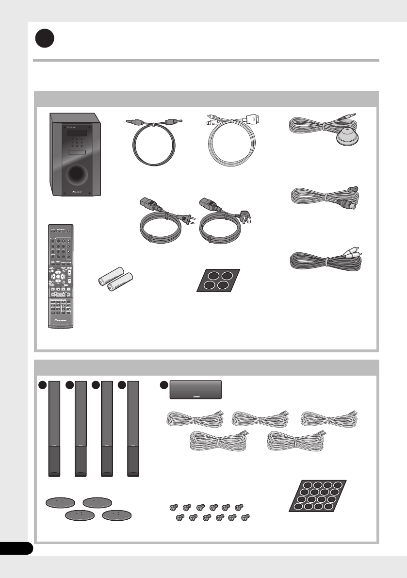
What’s in the box
Please confirm that the following items are all supplied.
1
SYSTEM
SYSTEM TV CONTROL
CH
VOL
DIMMER
SIGNAL SEL
BD MENU
DISPLAY
SURROUND SYSTEM
CH
CH
ENTER
ENTER
MUTE
INPUT
SOURCE
Large non-skid pads
(for receiver subwoofer) x4
iPod cable x1
Dry cell batteries
(AAA size IEC R03) x2
Microphone (for Auto
MCACC setup) x1
Remote control x1
Receiver subwoofer x1
FM wire antenna x1
Warranty card
Operating instructions
(This document)
Power cords x2
Receiver subwoofer (SX-SWR2) box
Optical digital cable x1
Video cable x1
A
C C
DE
B
Speakers (S-SWR600) box
Front speakers x2 Speaker cables
(for front speaker x2, for center speaker x1,
for surround speaker x2)
Brackets x2
Small non-skid pads
(for speaker stand bases) x18
Center speakers x2
Surround speakers x2 Mounting brackets x6 Screws x8
HTP-710_VYXCN_En.book 6 ページ 2010年8月23日 月曜日 午後6時47分
7
En
English Deutsch Italiano EspañolFrançais
Nederlands
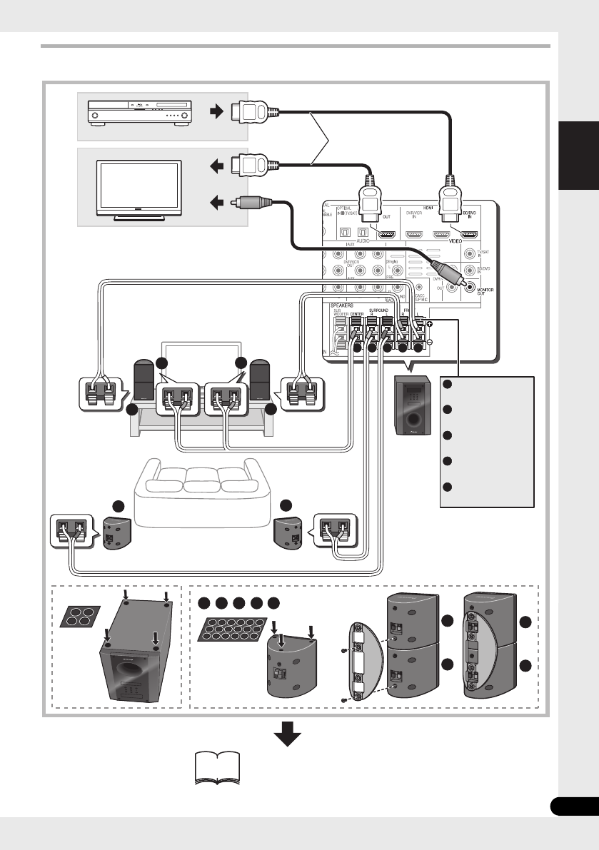
Connection
1 2
A
A
A
B
B
CC
C D E
DE
CC
B
E D B A
FRONT
-
L
FRONT
-
R
CENTER
SURROUND
-
L
SURROUND
-
R
A
B
C
D
E
HDMI OUT
HDMI IN
VIDEO IN
12
C
White
Red
Green
Blue
Grey
For enjoying your self
(MCACC)
Commercially
available
HTP-710_VYXCN_En.book 7 ページ 2010年8月23日 月曜日 午後6時47分

8
En
Setup Guide (HTP-FS510)
What’s in the box
Please confirm that the following items are all supplied.
1
SYSTEM
SYSTEM TV CONTROL
CH
VOL
DIMMER
SIGNAL SEL
BD MENU
DISPLAY
SURROUND SYSTEM
CH
CH
ENTER
ENTER
MUTE
INPUT
SOURCE
Large non-skid pads
(for receiver subwoofer) x4
iPod cable x1
Dry cell batteries
(AAA size IEC R03) x2
Microphone (for Auto
MCACC setup) x1
Remote control x1
Receiver subwoofer x1
FM wire antenna x1
Warranty card
Operating instructions
(This document)
Power cords x2
Receiver subwoofer (SX-SWR2) box
Optical digital cable x1
Video cable x1
A B
Speakers (S-SWR500FS) box
Front speakers x2
Speaker cables x2
Poles x2
Speaker stand bases x2 Gaskets x2
Screws (short) x8
Screws (long) x4
HTP-710_VYXCN_En.book 8 ページ 2010年8月23日 月曜日 午後6時47分

9
En
English Deutsch Italiano EspañolFrançais
Nederlands
Connection
2
A
AB
B
BA
HDMI OUT
HDMI IN
VIDEO IN
24
FRONT
-
L
FRONT
-
R
A
B
12
White
Red
For enjoying your self
(MCACC)
Commercially
available
HTP-710_VYXCN_En.book 9 ページ 2010年8月23日 月曜日 午後6時47分

10
En
Setup Guide (HTP-SB510)
What’s in the box
Please confirm that the following items are all supplied.
1
SYSTEM
SYSTEM TV CONTROL
CH
VOL
DIMMER
SIGNAL SEL
BD MENU
DISPLAY
SURROUND SYSTEM
CH
CH
ENTER
ENTER
MUTE
INPUT
SOURCE
Large non-skid pads
(for receiver subwoofer) x4
iPod cable x1
Dry cell batteries
(AAA size IEC R03) x2
Microphone (for Auto
MCACC setup) x1
Remote control x1
Receiver subwoofer x1
FM wire antenna x1
Warranty card
Operating instructions
(This document)
Power cords x2
Receiver subwoofer (SX-SWR2) box
Optical digital cable x1
Video cable x1
Speakers (S-SB510) box
Speaker x1 Speaker cable x1
Speaker stands x2
Screws x2
Small non-skid pads
(for speaker stands/for speaker) x10
HTP-710_VYXCN_En.book 10 ページ 2010年8月23日 月曜日 午後6時47分

11
En
English Deutsch Italiano EspañolFrançais
Nederlands
Connection
1 2
BA
FRONT
-
L
FRONT
-
R
CENTER
A
B
C
HDMI OUT
HDMI IN
VIDEO IN
12
C
A
C
B
White
Red
Green
For enjoying your self
(MCACC)
Commercially
available
HTP-710_VYXCN_En.book 11 ページ 2010年8月23日 月曜日 午後6時47分
12
En
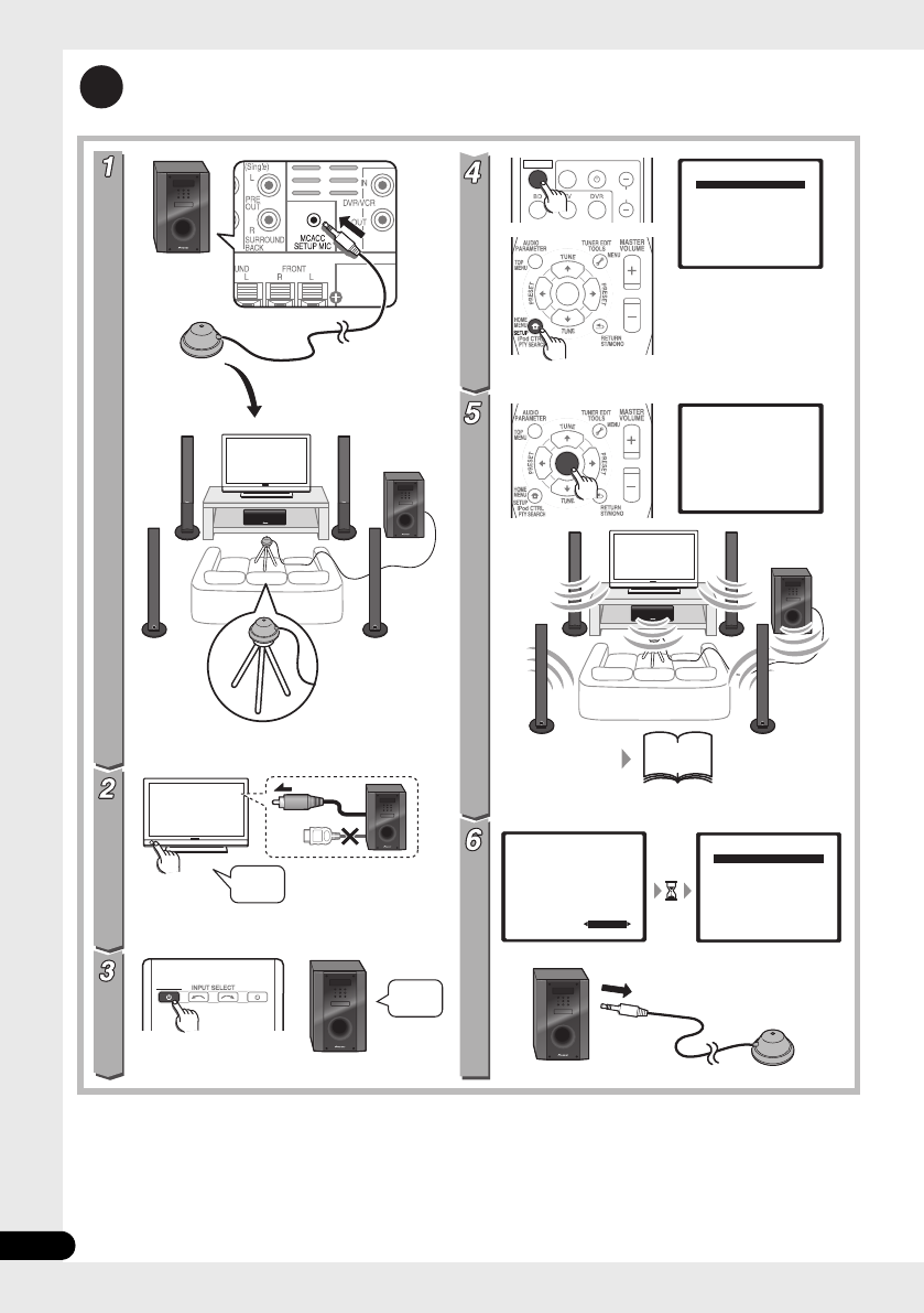
For enjoying your self (MCACC)
2
(HTP-710)
(HTP-710)
SYSTEM SOURCE
SYSTEM TV CONTROL
CH
INPUT
ENTER
ENTER
System Setup
1.Auto MCACC
2.Manual SP Setup
Return
System Setup
1.Auto MCACC
2.Manual SP Setup
Return
1.Auto MCACC
Now Analyzing
Environment Check
Ambient Noise
Speaker YES/NO
Return
1.Auto MCACC
Check!
OK
Return
10:Next
Front
Center
Surr
Surr. Back
Subwoofer
[ YES ]
[ YES ]
[ YES ]
[YESx2]
[ YES ]
51
-
53
?
VIDEO IN
HDMI
On
On
HTP-710_VYXCN_En.book 12 ページ 2010年8月23日 月曜日 午後6時47分

13
En
English Deutsch Italiano EspañolFrançais
Nederlands
Home theater
3
SYSTEM SOURCE
SYSTEM SOURCE
SYSTEM SOURCE
SYSTEM TV CONTROL
CH
VOL
INPUT
BD/DVD Radio
SYSTEM TV CONTROL
CH
VOL
DIMMER
SIGNAL SEL
BD MENU
INPUT
ENTER
HDMI IN
BD/DVD
TUNER
SYSTEM SOURCE
ENTER
75
On
On
Off
Off
Off
On
HTP-710_VYXCN_En.book 13 ページ 2010年8月23日 月曜日 午後6時47分

14
En
Thank you for buying this Pioneer product.
Please read through these operating instructions so that you will know how to operate your model
properly. After you have finished reading the instructions, put them in a safe place for future reference
.
Contents
Setup Guide
HTP-710.........................................4
HTP-610.........................................6
HTP-FS510 .....................................8
HTP-SB510...................................10
For enjoying your self (MCACC)...12
Home theater.................................13
01 Speaker Setup (HTP-710)
Safety precautions when setting up. . . . . .16
Home theater sound setup . . . . . . . . . . . .16
Preparing the speakers . . . . . . . . . . . . . . .16
Securing your front and surround
speakers . . . . . . . . . . . . . . . . . . . . . . . . .18
Wall mounting the center speaker. . . . . . .18
Before mounting . . . . . . . . . . . . . . . . . . .18
Additional notes on speaker placement. . .19
01 Speaker Setup (HTP-610)
Safety precautions when setting up. . . . . .20
Home theater sound setup . . . . . . . . . . . .20
Preparing the speakers . . . . . . . . . . . . . . .20
Wall mounting the speakers . . . . . . . . . . .22
Before mounting . . . . . . . . . . . . . . . . . . .22
Additional notes on speaker placement. . .23
01 Speaker Setup (HTP-FS510)
Safety precautions when setting up. . . . . .24
Home theater sound setup . . . . . . . . . . . .24
Preparing the speakers . . . . . . . . . . . . . . .24
Wall mounting the front speakers . . . . . . .26
Before mounting . . . . . . . . . . . . . . . . . . .26
Attaching the speakers . . . . . . . . . . . . . .27
Additional notes on speaker placement. . .27
For Enhanced Sound Quality . . . . . . . . . . .27
01 Speaker Setup (HTP-SB510)
Safety precautions when setting up . . . . . 28
Home theater sound setup . . . . . . . . . . . . 28
Preparing the speakers . . . . . . . . . . . . . . . 28
Wall mounting the speaker . . . . . . . . . . . . 30
Before mounting. . . . . . . . . . . . . . . . . . . 30
Additional notes on speaker placement . . 31
For Enhanced Sound Quality. . . . . . . . . . . 31
02 Connecting up
Rear panel. . . . . . . . . . . . . . . . . . . . . . . . . 32
Making cable connections . . . . . . . . . . . . 33
About video outputs connection . . . . . . . 33
HDMI cables. . . . . . . . . . . . . . . . . . . . . . 33
Analog audio cables . . . . . . . . . . . . . . . . 34
Digital audio cables . . . . . . . . . . . . . . . . 34
Connect your TV (For TV audio) . . . . . . . . . 35
Connecting your TV and playback
components . . . . . . . . . . . . . . . . . . . . . . . 36
Connecting using HDMI . . . . . . . . . . . . . 36
Connecting your component with no
HDMI terminal . . . . . . . . . . . . . . . . . . . . 37
Connecting an HDD/DVD recorder, VCR
and other video sources . . . . . . . . . . . . . . 38
Connecting a satellite receiver or other
digital set-top box . . . . . . . . . . . . . . . . . . . 39
Connecting other audio components . . . . 40
Connecting to the front panel video
terminal . . . . . . . . . . . . . . . . . . . . . . . . . . 41
Connecting an iPod/iPhone . . . . . . . . . . . 41
Connecting a USB device . . . . . . . . . . . . . 42
Connecting the FM antenna . . . . . . . . . . . 42
Connecting external antennas . . . . . . . . 42
Use the PRE OUT outputs to connect the
surround back speakers . . . . . . . . . . . . . . 43
Plugging in the system . . . . . . . . . . . . . . . 43
HTP-710_VYXCN_En.book 14 ページ 2010年8月23日 月曜日 午後6時47分

English Deutsch Italiano EspañolFrançais
Nederlands
15
En
03 Controls and displays
Front panel. . . . . . . . . . . . . . . . . . . . . . . . 44
Display. . . . . . . . . . . . . . . . . . . . . . . . . . 45
Remote control . . . . . . . . . . . . . . . . . . . . 47
Putting the batteries in the remote
control . . . . . . . . . . . . . . . . . . . . . . . . . . 50
Using the remote control. . . . . . . . . . . . 50
04 Getting started
Automatically setting up for surround
sound (MCACC) . . . . . . . . . . . . . . . . . . . . 51
Other problems when using the Auto
MCACC Setup . . . . . . . . . . . . . . . . . . . . 53
Basic operation . . . . . . . . . . . . . . . . . . . . 54
Choosing the input signal . . . . . . . . . . . 54
05 iPod/USB playback
Playing an iPod . . . . . . . . . . . . . . . . . . . . 55
iPod playback . . . . . . . . . . . . . . . . . . . . 55
Watching photos and video content . . . 57
About iPod/iPhone . . . . . . . . . . . . . . . . 57
Playing a USB device . . . . . . . . . . . . . . . . 58
Basic playback controls. . . . . . . . . . . . . 58
Compressed audio compatibility . . . . . . 59
06 Using the tuner
Listening to the radio . . . . . . . . . . . . . . . . 60
Improving FM stereo sound . . . . . . . . . . 60
Saving station presets . . . . . . . . . . . . . . . 60
Listening to station presets . . . . . . . . . . 61
Naming preset stations . . . . . . . . . . . . . 61
An introduction to RDS . . . . . . . . . . . . . . 61
Searching for RDS programs. . . . . . . . . 62
Displaying RDS information . . . . . . . . . 62
07 Listening to your system
Selecting Listening mode. . . . . . . . . . . . . 63
Auto playback . . . . . . . . . . . . . . . . . . . . . 63
Listening in surround sound . . . . . . . . . . 63
Using the Advanced surround effects . . 64
Listening in stereo . . . . . . . . . . . . . . . . . . 64
Using Front Stage Surround Advance . . . 65
Using Stream Direct . . . . . . . . . . . . . . . . 65
Using the Sound Retriever . . . . . . . . . . . . 65
Listening with Acoustic Calibration EQ . . 66
Better sound using Phase Control . . . . . . 66
Functions when surround back speakers
are connected . . . . . . . . . . . . . . . . . . . . . 67
Surround sound mode. . . . . . . . . . . . . . 67
Using surround back channel processing
. . . 68
Setting the Up Mix function . . . . . . . . . . 68
Setting the Audio options. . . . . . . . . . . . . 69
08 The System Setup menu
Using the System Setup menu . . . . . . . . .72
Manual speaker setup . . . . . . . . . . . . . . . .72
Speaker Setting. . . . . . . . . . . . . . . . . . . .73
Channel Level . . . . . . . . . . . . . . . . . . . . .73
Speaker Distance . . . . . . . . . . . . . . . . . .74
09 Controlling the rest of your system
Setting the remote to control other
components . . . . . . . . . . . . . . . . . . . . . . .75
Selecting preset codes directly . . . . . . . . .75
Clearing all the remote control settings. . .75
Controls for TVs . . . . . . . . . . . . . . . . . . . . .76
Controls for other components . . . . . . . . .77
Preset Code List . . . . . . . . . . . . . . . . . . . .79
10 Additional information
Troubleshooting. . . . . . . . . . . . . . . . . . . . .84
HDMI . . . . . . . . . . . . . . . . . . . . . . . . . . .86
Important information regarding the
HDMI connection . . . . . . . . . . . . . . . . . .87
iPod messages . . . . . . . . . . . . . . . . . . . .87
USB messages . . . . . . . . . . . . . . . . . . . .88
Resetting the main unit . . . . . . . . . . . . . . .88
Specifications . . . . . . . . . . . . . . . . . . . . . .88
SX-SWR2 Receiver subwoofer. . . . . . . . .88
S-DV595T Speaker system (HTP-710). . . .89
S-SWR600 Speaker system (HTP-610) . . .89
S-SWR500FS Speaker system
(HTP-FS510) . . . . . . . . . . . . . . . . . . . . . .90
S-SB510 Speaker system (HTP-SB510)
. . .90
Cleaning the unit . . . . . . . . . . . . . . . . . . . .90
HTP-710_VYXCN_En.book 15 ページ 2010年8月23日 月曜日 午後6時47分

Speaker Setup (HTP-710)01
16
En
Chapter 1-1
Speaker Setup (HTP-710)
Safety precautions when
setting up
When assembling the speakers, lay them down
flat on their side to avoid accidents or injury.
Make sure to use a stable surface when
assembling, setting up, and placing the
speakers.
Home theater sound setup
This is a standard multichannel surround
sound speaker setup for optimal 5.1 channel
home theater sound. The front left and right
speakers should be about 1.8 m to 2.7 m apart.
Preparing the speakers
1 Attach the non-skid pads to the base of
each speaker stand bases and the receiver
subwoofer.
For speaker stand bases:
Use the supplied adhesive to attach four small
pads to the base (bottom) of each speaker
stand base.
For subwoofer:
Use the supplied adhesive to attach four large
pads to the base of subwoofer.
Front left Front right
Surround left Surround right
Listening position
Center
Subwoofer
Small non-skid pads
Large non-skid pads
HTP-710_VYXCN_En.book 16 ページ 2010年8月23日 月曜日 午後6時47分

English Deutsch Italiano EspañolFrançais
Nederlands
Speaker Setup (HTP-710) 01
17
En
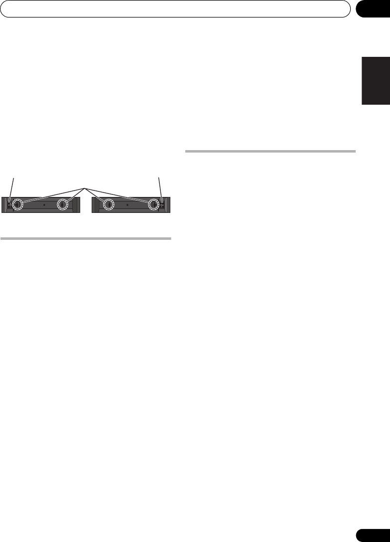
2 Attach the speaker stand bases to the
stems using the screws provided.
Once you have aligned the stem and base,
secure with the small screws at the points
shown below. Note that the speaker should
face in the direction of the base of the isosceles
triangle.
CAUTION
• Be careful not to tighten screws excessively.
• If excessive force is used to tighten screws,
the threads of screw and/or nut may be
damaged. Use a middle-sized manual
screwdriver during assembly.
• Do not use power screwdrivers or oversized
screwdrivers that may exert excessive force
on the screws and nuts.
• Confirm that no foreign matter is stuck to
the stand base or the tall speaker during
assembly.
• If the unit is assembled with foreign matter
stuck between the stand base and the tall
speaker the unit may not be assembled
securely, resulting in tipping or falling.
• Do not stand on the speaker stand base of
the tall speaker to push or swing the
speaker. The speaker may fall and break, or
someone may be injured. Pay special
attention to children.
3 Connect each speaker.
Connect the wires to the speaker. Each
speaker in the illustration can be identified by
means of the color-coded indicator provided
on the rear-surface label.
Front left: White
Front right: Red
Center: Green
Surround left: Blue
Surround right: Gray
Match the color-coded wire with the color
indicator on the label, then insert the color-
coded wire into the red (+) side and the other
wire into the black (–) side.
Connect the other end to the color-coded
speaker terminals on the rear of the receiver
subwoofer.
Rear
Front
Black
(–)
Red (+) Color-coded wire
Black
(–)
Color-coded wire
Color-coded tab (+)
HTP-710_VYXCN_En.book 17 ページ 2010年8月23日 月曜日 午後6時47分
Speaker Setup (HTP-710)01
18
En
CAUTION
• These speaker terminals carry
HAZARDOUS LIVE voltage. To prevent
the risk of electric shock when connecting
or disconnecting the speaker cables,
disconnect the power cord before touching
any uninsulated parts.
• Do not connect any speakers other than
those supplied to this system.
• Do not connect the supplied speakers to
any amplifier other than the one supplied
with this system. Connection to any other
amplifier may result in malfunction or fire.
• After connecting the plugs, pull lightly on
the cables to make sure that the ends of
the cables are securely connected to the
terminals. Poor connections can create
noise and interruptions on the sound.
• If the cable’s wires happen to be pushed
out of the terminals, allowing the wires to
come into contact with each other, it
places an excessive additional load on the
amp. This may cause the amp to stop
functioning, and may even damage the
amp.
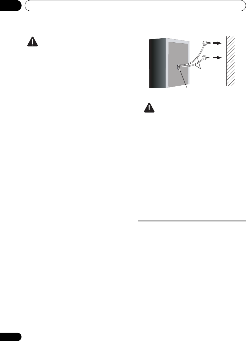
Securing your front and surround
speakers
• Secure each of the front and surround
speakers using the plastic catch provided.
Screw two supporting hooks into the wall
behind the speaker. Pass a thick cord around
the hooks and through the plastic catch so that
the speaker is stabilized (make sure to test that
it supports the weight of the speaker). After
installing, make sure the speaker is securely
fixed.
CAUTION
• The plastic catch is not a mounting fixture,
and the speaker should not be hung
directly from the wall using this catch.
Always use a cord when stabilizing the
speaker.
• Pioneer disclaims all responsibility for any
losses or damage resulting from improper
assembly, installation, insufficient
strength of the installation materials,
misuse, or natural disasters.
• When placing this unit, ensure that it is
firmly secured and avoid areas where it
may be likely to fall and cause injury in the
event of a natural disaster (such as an
earthquake).
Wall mounting the center
speaker
The center speaker have a mounting hole
which can be used to mount the speaker on the
wall.
Before mounting
• Remember that the speaker system is
heavy and that its weight could cause the
screws to work loose, or the wall material to
fail to support it, resulting in the speaker
falling. Make sure that the wall you intend
to mount the speakers on is strong enough
to support them. Do not mount on plywood
or soft surface walls.
Sufficiently
thick cord
Plastic catch
HTP-710_VYXCN_En.book 18 ページ 2010年8月23日 月曜日 午後6時47分

English Deutsch Italiano EspañolFrançais
Nederlands
Speaker Setup (HTP-710) 01
19
En
• Mounting screws are not supplied. Use
screws suitable for the wall material and
support the weight of the speaker.
CAUTION
• If you are unsure of the qualities and
strength of the wall, consult a professional
for advice.
• Pioneer is not responsible for any
accidents or damage that result from
improper installation.
Additional notes on speaker
placement
• Install the main front left and right
speakers at an equal distance from the TV.
• Install the surround speakers slightly
above ear level for optimum effect.
• Televisions supporting 3D display transmit
signals to the 3D glasses worn by the
viewer. In order to view 3D images, consult
the television’s Operating Instructions and
install the center speaker so that it does
not block the television’s 3D signal
transmitter.
Precautions:
• When installing the center speaker on top of
the TV, be sure to secure it with tape or
some other suitable means. Otherwise, the
speaker may fall from the TV due to external
shocks such as earthquakes, endangering
those nearby or damaging the speaker.
• Make sure that all the bare speaker wire is
twisted together and inserted fully into the
speaker terminal. If any of the bare speaker
wire touches the back panel it may cause
the power to cut off as a safety measure.
• The front, center and surround speakers
supplied with this system are magnetically
shielded. However, depending on the
installation location, color distortion may
occur if the speaker is installed extremely
close to the screen of a television set. If this
case happens, turn the power switch of the
television set OFF, and turn it ON after
15 min. to 30 min. If the problem persists,
place the speaker system away from the
television set.
• The subwoofer is not magnetically shielded
and so should not be placed near a TV or
monitor. Magnetic storage media (such as
floppy discs and tape or video cassettes)
should also not be kept close to the
subwoofer.
• Do not attach the front/surround speakers
and subwoofer to a wall or ceiling. They
may fall off and cause injury.
• Do not stand on the speaker stand base of
the tall speaker to push or swing the
speaker. The speaker may fall and break, or
someone may be injured. Pay special
attention to children.
5 mm
10 mm
Mounting screw
(not supplied)
5 mm to 7 mm
HTP-710_VYXCN_En.book 19 ページ 2010年8月23日 月曜日 午後6時47分

Speaker Setup (HTP-610)01
20
En
Chapter 1-2
Speaker Setup (HTP-610)
Safety precautions when
setting up
When assembling the speakers, lay them down
flat on their side to avoid accidents or injury.
Make sure to use a stable surface when
assembling, setting up, and placing the
speakers.
If the speakers are to be used in a stacked
configuration, always use the provided
brackets to secure them together (page 21).
Home theater sound setup
This is a standard multichannel surround
sound speaker setup for optimal 5.1 channel
home theater sound. The front left and right
speakers should be about 1.8 m to 2.7 m apart.
Preparing the speakers
1 Attach the non-skid pads to the base of
each speakers and the receiver subwoofer.
For front, center and surround speakers:
Use the supplied adhesive to attach three pads
to the base (bottom) of each speaker.
For subwoofer:
Use the supplied adhesive to attach four large
pads to the base of subwoofer.
Front left
Front right
Surround left Surround right
Listening position
Subwoofer
Center Center
*When center speakers are placed in the center.
Center
Front left Front right
Small non-skid pads
Large non-skid pads
HTP-710_VYXCN_En.book 20 ページ 2010年8月23日 月曜日 午後6時47分

Speaker Setup (HTP-610) 01
21
En
English Deutsch Italiano EspañolFrançais
Nederlands
2 (When mounting center speakers to right
and left) Stack the speakers and fix with the
bracket.
Each speaker is provided with a color-coded
indicator on the model label on the rear side to
assist identification. Refer to the color
indicators and install the speakers correctly.
As shown in the illustration, stack the
speakers. Align the bracket with the respective
upper and lower screw holes as shown in each
figure below and fasten the screws securely.
CAUTION
• Do not attempt to carry the speakers when
they are connected with the bracket. Doing
so may cause damage to the bracket or
worsen damage to the bracket and
speakers in the event they are dropped.
3 Connect each speaker.
Connect the wires to the speaker. Each
speaker in the illustration can be identified by
means of the color-coded indicator provided
on the rear-surface label.
Front left: White
Front right: Red
Center: Green
Surround left: Blue
Surround right: Gray
Match the color-coded wire with the color
indicator on the label, then insert the color-
coded wire into the red (+) side and the other
wire into the black (–) side.
• When connecting the center speakers,
connect the Y-cable dual end to the two
center speakers in the same way.
Model label
Color indicator
Left Right
Green
Center
speaker
Front
speaker
Green
White Red
Bracket
Screw
Center
speaker
Front
speaker
Black
(–)
Red (+) Color-coded wire
Y-cable
To receiver subwoofer
HTP-710_VYXCN_En.book 21 ページ 2010年8月23日 月曜日 午後6時47分

Speaker Setup (HTP-610)01
22
En
Connect the other end to the color-coded
speaker terminals on the rear of the receiver
subwoofer.
CAUTION
• These speaker terminals carry
HAZARDOUS LIVE voltage. To prevent
the risk of electric shock when connecting
or disconnecting the speaker cables,
disconnect the power cord before touching
any uninsulated parts.
• Do not connect any speakers other than
those supplied to this system.
• Do not connect the supplied speakers to
any amplifier other than the one supplied
with this system. Connection to any other
amplifier may result in malfunction or fire.
• After connecting the plugs, pull lightly on
the cables to make sure that the ends of
the cables are securely connected to the
terminals. Poor connections can create
noise and interruptions on the sound.
• If the cable’s wires happen to be pushed
out of the terminals, allowing the wires to
come into contact with each other, it
places an excessive additional load on the
amp. This may cause the amp to stop
functioning, and may even damage the
amp.
Wall mounting the speakers
All the speakers (except the subwoofer, which
should be placed on the ground) have holes for
mounting brackets, and depending on the
speaker setup you choose, you can wall-mount
the front, center and surround speakers.
• Make sure to tighten the supplied screw as
securely as possible when attaching the
bracket to the back of the speaker.
Before mounting
• Remember that the speaker system is
heavy and that its weight could cause the
screws to work loose, or the wall material to
fail to support it, resulting in the speaker
falling. Make sure that the wall you intend
to mount the speakers on is strong enough
to support them. Do not mount on plywood
or soft surface walls.
• Mounting screws are not supplied. Use
screws suitable for the wall material and
support the weight of the speaker.
CAUTION
• If you are unsure of the qualities and
strength of the wall, consult a professional
for advice.
• Pioneer is not responsible for any
accidents or damage that result from
improper installation.
Black
(–)
Color-coded wire
Color-coded tab (+)
HTP-710_VYXCN_En.book 22 ページ 2010年8月23日 月曜日 午後6時47分

Speaker Setup (HTP-610) 01
23
En
English Deutsch Italiano EspañolFrançais
Nederlands
Additional notes on speaker
placement
• Install the main front left and right
speakers at an equal distance from the TV.
• Install the surround speakers slightly
above ear level for optimum effect.
• Televisions supporting 3D display transmit
signals to the 3D glasses worn by the
viewer. In order to view 3D images, consult
the television’s Operating Instructions and
install the center speaker so that it does
not block the television’s 3D signal
transmitter.
Precautions:
• When installing the center speaker on top
of the TV, be sure to secure it with tape or
some other suitable means. Otherwise, the
speaker may fall from the TV due to
external shocks such as earthquakes,
endangering those nearby or damaging
the speaker.
• The front, center and surround speakers
supplied with this system are magnetically
shielded. However, depending on the
installation location, color distortion may
occur if the speaker is installed extremely
close to the screen of a television set. If this
case happens, turn the power switch of the
television set OFF, and turn it ON after 15
min. to 30 min. If the problem persists,
place the speaker system away from the
television set.
• The subwoofer is not magnetically shielded
and so should not be placed near a TV or
monitor. Magnetic storage media (such as
floppy discs and tape or video cassettes)
should also not be kept close to the
subwoofer.
• Do not attach the subwoofer to the wall or
ceiling. They may fall off and cause injury.
Mounting bracket
(supplied)
Screw (supplied)
5 mm to 7 mm
Mounting screw
(not supplied) 5 mm
10 mm
HTP-710_VYXCN_En.book 23 ページ 2010年8月23日 月曜日 午後6時47分

Speaker Setup (HTP-FS510)01
24
En
Chapter 1-3
Speaker Setup (HTP-FS510)
Safety precautions when
setting up
When assembling the speakers, lay them down
flat on their side to avoid accidents or injury.
Make sure to use a stable surface when
assembling, setting up, and placing the
speakers.
Home theater sound setup
This is a standard speaker setup. The front left
and right speakers should be about 1.8 m to 2.7
m apart.
Preparing the speakers
1 Attach the non-skid pads to the base of
receiver subwoofer.
Use the supplied adhesive to attach four pads
to the base of subwoofer.
2 Insert the pole from the holes behind the
base and secure with the 4 screws.
CAUTION
• Be careful not to tighten screws excessively.
• If excessive force is used to tighten screws,
the threads of screw and/or nut may be
damaged. Use a middle-sized manual
screwdriver during assembly.
• Do not use power screwdrivers or oversized
screwdrivers that may exert excessive force
on the screws and nuts.
• Confirm that no foreign matter is stuck to
the stand base or the tall speaker during
assembly.
• If the unit is assembled with foreign matter
stuck between the stand base and the tall
speaker the unit may not be assembled
securely, resulting in tipping or falling.
3 Affix the gasket to the pole.
Affix the gasket to the surface of the pole where
the speaker will be mounted.
Front left Front right
Subwoofer
Non-skid pads
HTP-710_VYXCN_En.book 24 ページ 2010年8月23日 月曜日 午後6時47分

Speaker Setup (HTP-FS510) 01
25
En
English Deutsch Italiano EspañolFrançais
Nederlands
4 Insert the speaker cable from the hole
behind the base through to the pole.
5 Connect each speaker.
Connect the wires to the speaker. Each
speaker in the illustration can be identified by
means of the color-coded indicator provided on
the rear-surface label.
Front left: White
Front right: Red
Match the color-coded wire with the color
indicator on the label, then insert the color-
coded wire into the red (+) side and the other
wire into the black (–) side.
Connect the other end to the color-coded
speaker terminals on the rear of the receiver
subwoofer.
• When connections are completed, secure
the speaker cables. Fix the cables to the
groove in the speakers.
CAUTION
• These speaker terminals carry
HAZARDOUS LIVE voltage. To prevent
the risk of electric shock when connecting
or disconnecting the speaker cables,
disconnect the power cord before touching
any uninsulated parts.
• Only those speakers supplied, or
purchased as an officially supported
option, should be connected to this
system.
• Do not connect the supplied speakers to
any amplifier other than the one supplied
with this system. Connection to any other
amplifier may result in malfunction or fire.
• After connecting the plugs, pull lightly on
the cables to make sure that the ends of
the cables are securely connected to the
terminals. Poor connections can create
noise and interruptions on the sound.
• If the cable’s wires happen to be pushed
out of the terminals, allowing the wires to
come into contact with each other, it
places an excessive additional load on the
amp. This may cause the amp to stop
functioning, and may even damage the
amp.
Black
(–)
Red (+) Color-coded wire
Black
(–)
Color-coded wire
Color-coded tab (+)
HTP-710_VYXCN_En.book 25 ページ 2010年8月23日 月曜日 午後6時47分

Speaker Setup (HTP-FS510)01
26
En
6 Secure the speaker and the pole with 2
screws.
• Confirm that the speaker cable does not
become pinched between the pole and the
speaker.
•Put the speaker cable in the back of the base
of the stand.
Wall mounting the front
speakers
The front speakers have a mounting hole which
can be used to mount the speaker on the wall.
Before mounting
• Remember that the speaker system is
heavy and that its weight could cause the
screws to work loose, or the wall material to
fail to support it, resulting in the speaker
falling. Make sure that the wall you intend
to mount the speakers on is strong enough
to support them. Do not mount on plywood
or soft surface walls.
• Mounting screws are not supplied. Use
screws suitable for the wall material and
support the weight of the speaker.
CAUTION
• If you are unsure of the qualities and
strength of the wall, consult a professional
for advice.
• Pioneer is not responsible for any
accidents or damage that result from
improper installation.
5 mm
10 mm
Mounting screw
(not supplied)
5 mm to 7 mm
HTP-710_VYXCN_En.book 26 ページ 2010年8月23日 月曜日 午後6時47分
Speaker Setup (HTP-FS510) 01
27
En
English Deutsch Italiano EspañolFrançais
Nederlands
Attaching the speakers
The front speaker can be hung vertically or
horizontally on the wall. Use one hole to hang
it vertically and two holes to hang it
horizontally.
When installing the speaker horizontally, set it
up so that the speaker terminal on the back
side of the speaker is on the outside on the end
of the surface, farthest away from the other
speaker.
Additional notes on speaker
placement
• Install the front left and right speakers at
an equal distance from the TV.
Precautions:
• Make sure that all the bare speaker wire is
twisted together and inserted fully into the
speaker terminal. If any of the bare speaker
wire touches the back panel it may cause
the power to cut off as a safety measure.
• The front speakers supplied with this
system are magnetically shielded.
However, depending on the installation
location, color distortion may occur if the
speaker is installed extremely close to the
screen of a television set. If this case
happens, turn the power switch of the
television set OFF, and turn it ON after
15 min. to 30 min. If the problem persists,
place the speaker system away from the
television set.
• The subwoofer is not magnetically shielded
and so should not be placed near a TV or
monitor. Magnetic storage media (such as
floppy discs and tape or video cassettes)
should also not be kept close to the
subwoofer.
• Do not attach the subwoofer to a wall or
ceiling. They may fall off and cause injury.
For Enhanced Sound Quality
A home theater system can be easily
constructed using just the front (right/left)
speakers and the subwoofer of this set, but by
adding optional S-SWR5CR speaker systems,
you can enjoy genuine 5.1 channel surround
sound.
Take the following points into account when
connecting the optional speaker systems:
• When the contents of these Operating
Instructions from chapter 2 on describe a
specific model, use those portions dealing
with the HTP-610.
• For information regarding the installation
and connection of optional speaker
systems, consult the information provided
with the optional speaker systems,
together Speaker Setup (HTP-610) on
page 20 portion of these Operating
Instructions.
• See Automatically setting up for surround
sound (MCACC) on page 51 to set up your
system again using MCACC.
Mounting holes
Speaker terminal
Speaker terminal
Front right Front left
HTP-710_VYXCN_En.book 27 ページ 2010年8月23日 月曜日 午後6時47分

Speaker Setup (HTP-SB510)01
28
En
Chapter 1-4
Speaker Setup (HTP-SB510)
Safety precautions when
setting up
When assembling the speakers, lay them down
flat on their side to avoid accidents or injury.
Make sure to use a stable surface when
assembling, setting up, and placing the
speakers.
Home theater sound setup
The speaker should be installed below (in front
of) the TV. The height of the speaker stands can
be adjusted, or the speaker can be installed
without using the stands at all.
• The speaker and subwoofer are not
magnetically shielded and so should not be
used with CRT TV.
Preparing the speakers
1 Attach the non-skid pads to the base of
each speaker stands and the receiver
subwoofer.
For speaker stands:
Use the supplied adhesive to attach three
small pads to the base (bottom) of each
speaker stand.
For subwoofer:
Use the supplied adhesive to attach four large
pads to the base of subwoofer.
Speaker Subwoofer
Small non-skid pads
Large non-skid pads
HTP-710_VYXCN_En.book 28 ページ 2010年8月23日 月曜日 午後6時47分

Speaker Setup (HTP-SB510) 01
29
En
English Deutsch Italiano EspañolFrançais
Nederlands
If you decide not to use the speaker stands, use
the supplied adhesive to attach four small pads
to the base of the speaker.
2 Attach the speaker stand bases to the
speaker.
Attach both right and left speaker stands to the
rear of the speaker. The height of the speaker
stands can be adjusted in two levels; select the
height you prefer, and fix in position.
CAUTION
• Be careful not to tighten screws excessively.
• If excessive force is used to tighten screws,
the threads of screw may be damaged. Use
a middle-sized manual screwdriver during
assembly.
• Do not use power screwdrivers or oversized
screwdrivers that may exert excessive force
on the screws.
• Confirm that no foreign matter is stuck to
the stand or the speaker during assembly.
• If the unit is assembled with foreign matter
stuck between the stand and the speaker
the unit may not be assembled securely,
resulting in tipping or falling.
3 Connect each speaker.
Connect the wires to the speaker.
The rear of the speaker has channel terminals
(Right/Center/Left), together with color-coded
labels.
Front left: White
Front right: Red
Center: Green
Match the color-coded wire with the color
indicator on the label, then insert the color-
coded wire into the red (+) side and the other
wire into the black (–) side.
Connect the other end to the color-coded
speaker terminals on the rear of the receiver
subwoofer.
Small non-skid pads
Black
(–)
Red (+) Color-coded wire
Black
(–)
Color-coded wire
Color-coded tab (+)
HTP-710_VYXCN_En.book 29 ページ 2010年8月23日 月曜日 午後6時47分

Speaker Setup (HTP-SB510)01
30
En
CAUTION
• These speaker terminals carry
HAZARDOUS LIVE voltage. To prevent
the risk of electric shock when connecting
or disconnecting the speaker cables,
disconnect the power cord before touching
any uninsulated parts.
• Do not connect any speakers other than
those supplied to this system.
• Do not connect the supplied speaker to any
amplifier other than the one supplied with
this system. Connection to any other
amplifier may result in malfunction or fire.
• After connecting the plugs, pull lightly on
the cables to make sure that the ends of
the cables are securely connected to the
terminals. Poor connections can create
noise and interruptions on the sound.
• If the cable’s wires happen to be pushed
out of the terminals, allowing the wires to
come into contact with each other, it
places an excessive additional load on the
amp. This may cause the amp to stop
functioning, and may even damage the
amp.
Wall mounting the speaker
The speaker have the mounting holes which
can be used to mount the speaker on the wall.
Before mounting
• Remember that the speaker system is
heavy and that its weight could cause the
screws to work loose, or the wall material to
fail to support it, resulting in the speaker
falling. Make sure that the wall you intend
to mount the speaker on is strong enough
to support them. Do not mount on plywood
or soft surface walls.
• Mounting screws are not supplied. Use
screws suitable for the wall material and
support the weight of the speaker.
CAUTION
• If you are unsure of the qualities and
strength of the wall, consult a professional
for advice.
• Pioneer is not responsible for any
accidents or damage that result from
improper installation.
• When mounting the speaker on a wall,
install it so that it is parallel to the floor.
• When mounting the speaker on a wall, do
not attach the accessory speaker stands.
5 mm
10 mm
Mounting screw
(not supplied)
4 mm to 5 mm
460 mm
HTP-710_VYXCN_En.book 30 ページ 2010年8月23日 月曜日 午後6時47分

Speaker Setup (HTP-SB510) 01
31
En
English Deutsch Italiano EspañolFrançais
Nederlands
Additional notes on speaker
placement
• Install the speaker below the TV, in the
center position.
• Televisions supporting 3D display transmit
signals to the 3D glasses worn by the
viewer. In order to view 3D images, consult
the television’s Operating Instructions and
install the speaker so that it does not block
the television’s 3D signal transmitter.
Precautions:
• Do not rest the speaker on the TV itself.
• Make sure that all the bare speaker wire is
twisted together and inserted fully into the
speaker terminal. If any of the bare speaker
wire touches the back panel it may cause
the power to cut off as a safety measure.
• The speaker and subwoofer are not
magnetically shielded and so should not be
placed near a TV or monitor. Magnetic
storage media (such as floppy discs and
tape or video cassettes) should also not be
kept close to the speaker and subwoofer.
• Do not attach the subwoofer to a wall or
ceiling. They may fall off and cause injury.
For Enhanced Sound Quality
A home theater system can be easily
constructed using just the speaker and the
subwoofer of this set, but by adding optional S-
SB5R speaker systems, you can enjoy genuine
5.1 channel surround sound.
Take the following points into account when
connecting the optional speaker systems:
• When the contents of these Operating
Instructions from chapter 2 on describe a
specific model, use those portions dealing
with the HTP-610.
• For information regarding the installation
and connection of optional speaker
systems, consult the information provided
with the optional speaker systems,
together Speaker Setup (HTP-610) on
page 20 portion of these Operating
Instructions.
• See Automatically setting up for surround
sound (MCACC) on page 51 to set up your
system again using MCACC.
HTP-710_VYXCN_En.book 31 ページ 2010年8月23日 月曜日 午後6時47分
Connecting up02
32
En
Chapter 2
Connecting up
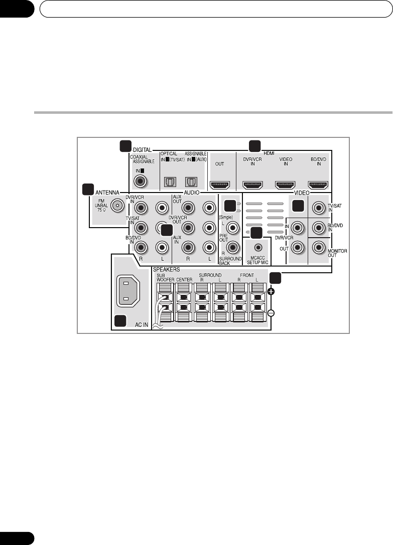
Rear panel
1 Coaxial/Optical digital audio inputs (x3)
Use the supplied optical digital cable to
connect the DIGITAL OPTICAL IN 1 (TV/SAT)
input to the television’s optical digital output
terminal.
Use for digital audio sources, including DVD
players/recorders, digital satellite receivers,
CD players, etc.
2 HDMI inputs (x3)/output (x1)
Multiple inputs and one output for high-quality
audio/video connection to compatible HDMI
devices.
3
FM
antenna socket
4 Stereo analog audio inputs/outputs
Use for connection to audio sources such as
CD players, tape decks, turntables, etc.
5 Surround back pre-amplifier outputs
Use to connect separate amplifiers for
surround back channels.
6
MCACC SETUP MIC
jack
Use to connect the supplied microphone for
the Auto MCACC setup (page 51).
7 Video inputs/outputs
Use the supplied video cable to connect the
MONITOR OUT terminal to the television’s
video input terminal.
Use for connection to video sources, such as
DVD players/recorders, VCRs, etc.
8
AC IN
– Power inlet
9
SPEAKERS
terminals
Match the colors of the speaker cables to their
respective connectors.
1
1 2
7
8
9
6
5
4
3
21
HTP-710_VYXCN_En.book 32 ページ 2010年8月23日 月曜日 午後6時47分
Connecting up 02
33
En
English Deutsch Italiano EspañolFrançais
Nederlands
Making cable connections
Make sure not to bend the cables over the top
of this unit. If this happens, the magnetic field
produced by the transformers in this unit may
cause a humming noise from the speakers.
CAUTION
• When connecting this system or changing
connections, be sure to switch power off
and disconnect the power cord from the
wall socket.
After completing all connections, connect
the power cords to the wall socket.
About video outputs connection
This system is not loaded with a video
converter. When you use HDMI cable for
connecting to the input device, the same
cables should be used for connecting to the TV.
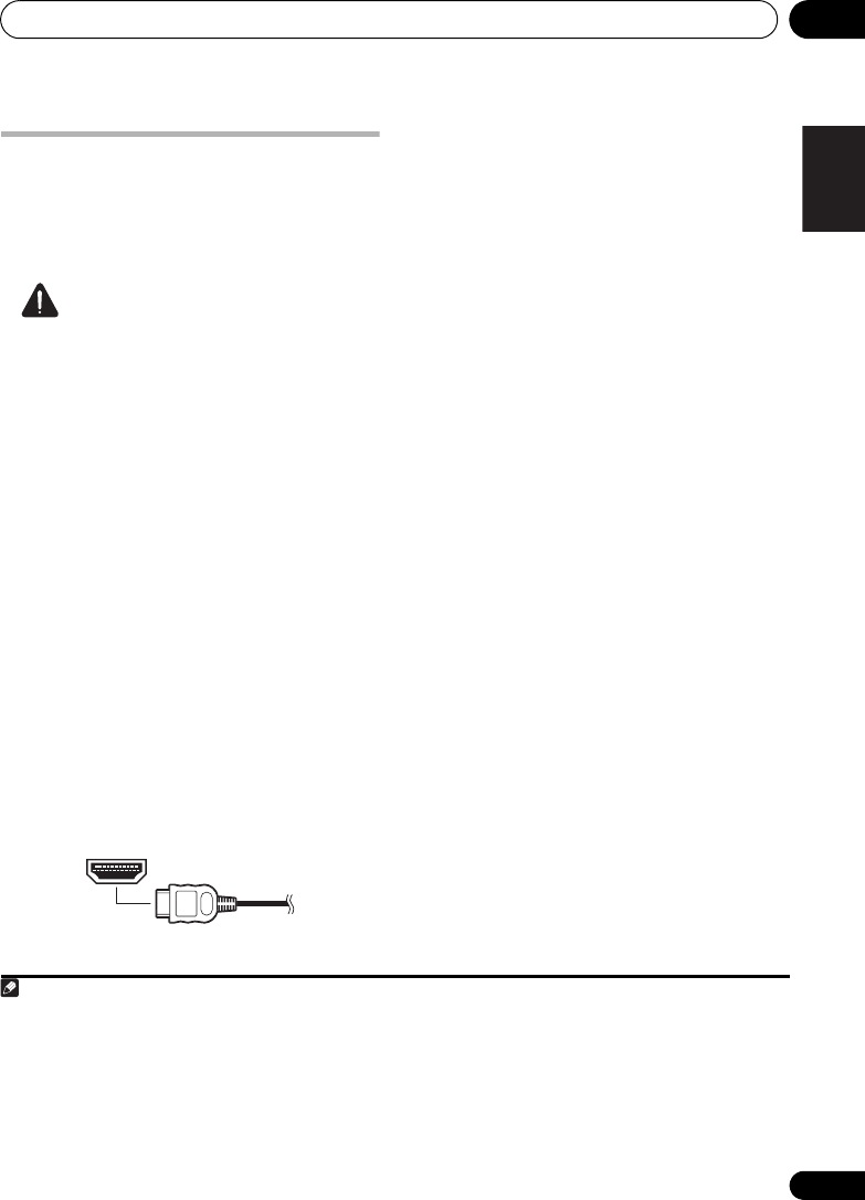
HDMI cables
The HDMI cables transfers uncompressed
digital video, as well as almost every kind of
digital audio that the connected component is
compatible with, including DVD-video, DVD-
Audio, Dolby Digital Plus, Dolby TrueHD, DTS-
HD Master Audio (see below for limitations),
Video CD/Super VCD, CD, SACD (DSD 2 ch
only) and 192 kHz/8 ch (Max. number of
channel inputs) PCM.1
Be careful to connect the terminal in the
proper direction.
About HDMI
HDMI (High Definition Multimedia Interface)
supports both video and audio on a single
digital connection for use with DVD players,
DTV, set-top boxes, and other AV devices.
HDMI was developed to provide the
technologies of High Bandwidth Digital
Content Protection (HDCP) as well as Digital
Visual Interface (DVI) in one specification.
HDCP is used to protect digital content
transmitted and received by DVI-compliant
displays.
HDMI has the capability to support standard,
enhanced, or high-definition video plus
standard to multi-channel surround-sound
audio. HDMI features include uncompressed
digital video, a bandwidth of up to 2.2 gigabytes
per second (with HDTV signals), one connector
(instead of several cables and connectors),
and communication between the AV source
and AV devices such as DTVs.
This system is also compatible with the
DeepColor and x.v.Color feature (x.v.Color is
trademarks of Sony Corporation).
HDMI, the HDMI Logo and High-Definition
Multimedia Interface are trademarks or
registered trademarks of HDMI Licensing, LLC in
the United States and other countries.
Note
1 • Set the HDMI parameter in Setting the Audio options on page 69 to THRU (THROUGH) and set the input signal in
Choosing the input signal on page 54 to HDMI, if you want to hear HDMI audio output from your TV (no sound will be
heard from this system).
• If the video signal does not appear on your TV, try adjusting the resolution settings on your component or display.
Note that some components (such as video game units) have resolutions that may not be displayed. In this case, use
a (analog) composite connection.
• The signals input from the (analog) composite video inputs of this unit will not be output from the HDMI OUT.
• When the video signal from the HDMI is 480i, 480p, 576i or 576p, Multi Ch PCM sound and HD sound cannot be
received.
HTP-710_VYXCN_En.book 33 ページ 2010年8月23日 月曜日 午後6時47分

Connecting up02
34
En
Important
• Compared to existing digital audio
transmission formats (optical and coaxial),
HDMI format digital audio transmissions
requires a longer time to be recognized.
Due to this, interruption in the audio may
occur when switching between formats or
beginning playback.
Additionally, turning on/off the component
connected to this unit’s HDMI OUT
terminal or disconnecting/connecting the
HDMI cable may cause noise or
interrupted audio.
Analog audio cables
Use stereo RCA phono cables to connect
analog audio components. These cables are
typically red and white, and you should
connect the red plugs to R (right) terminals
and white plugs to L (left) terminals.
Digital audio cables
Commercially available coaxial digital audio
cables or optical cables should be used to
connect digital components to this system.1
Coaxial digital audio cable
Optical cable
• A cap has been factory-attached to the
connector on the accessory optical digital
cable. Be sure to remove the cap before
connecting the cable.
Standard RCA video cables
These cables are the most common type of
video connection and are used to connect to
the composite video terminals. The yellow
plugs distinguish them from cables for audio.
Note
1 • When connecting optical cables, be careful when inserting the plug not to damage the shutter protecting the optical
socket.
• When storing optical cable, coil loosely. The cable may be damaged if bent around sharp corners.
• You can also use a standard RCA video cable for coaxial digital connections.
HTP-710_VYXCN_En.book 34 ページ 2010年8月23日 月曜日 午後6時47分
Connecting up 02
35
En
English Deutsch Italiano EspañolFrançais
Nederlands
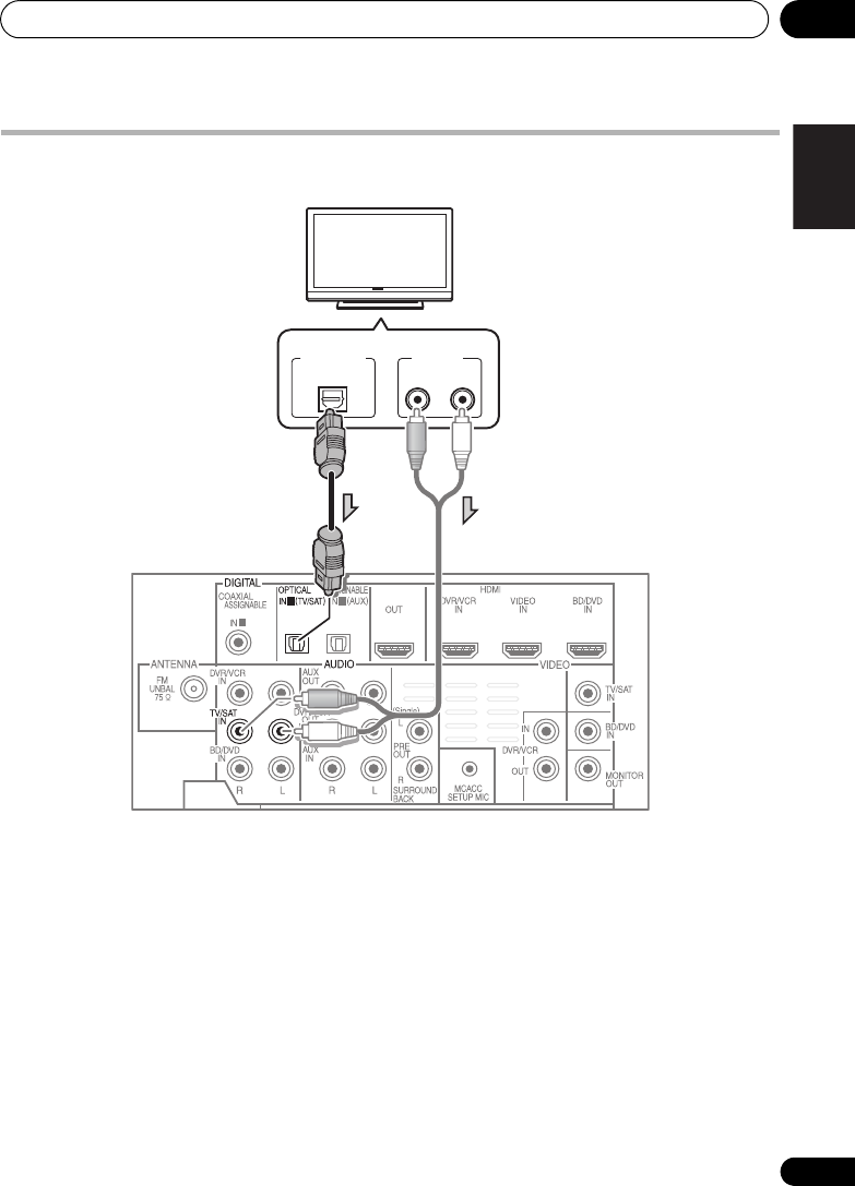
Connect your TV (For TV audio)
This will allow you to play the sound from the TV’s built-in tuner.
• Connect the digital audio output from
your TV to the
DIGITAL OPTICAL IN 1 (TV/
SAT)
input on this system.
Use the supplied optical digital cable.
• If your TV has no optical digital audio
output, you can connect an analog audio
outputs from your TV to the AUDIO TV/
SAT inputs on this system. Use an analog
audio cables for the connection.
1
1 2
DIGITAL OUT
OPTICAL ANALOG
RL
AUDIO OUT
TV
Select one
HTP-710_VYXCN_En.book 35 ページ 2010年8月23日 月曜日 午後6時47分
Connecting up02
36
En
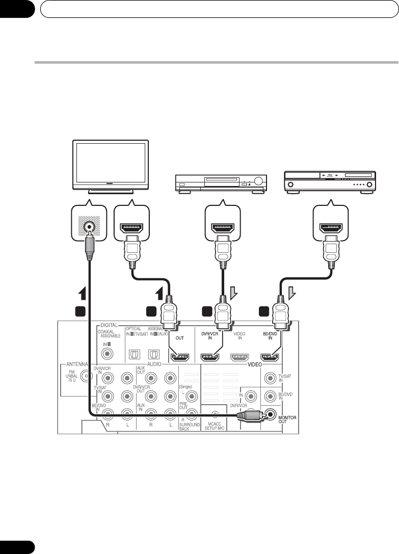
Connecting your TV and playback components
Connecting using HDMI
If you have an HDMI or DVI (with HDCP) equipped component (Blu-ray disc player, etc.), you can
connect it to this system using a commercially available HDMI cable.
1 Connect the HDMI output on your BD/
DVD player to the HDMI BD/DVD IN input on
this system.
Use an HDMI cable for the connection.
2 Connect the HDMI OUT on this system to
an HDMI input on your TV.
3 Connect the MONITOR OUT on this
system to the composite video input on your
TV.
The OSD will not appear if you have connected
using the HDMI output to your TV. Use
composite connections for system setup.
Use the supplied video cable.
1
1 2
1 1
2
3
VIDEO IN
HDMI OUTHDMI IN HDMI OUT
HDMI/DVI-compatible TV
HDMI/DVI-equipped
component
HDMI/DVI-compatible
Blu-ray disc player
HTP-710_VYXCN_En.book 36 ページ 2010年8月23日 月曜日 午後6時47分

Connecting up 02
37
En
English Deutsch Italiano EspañolFrançais
Nederlands
Connecting your component with no HDMI terminal
This diagram shows connections of a TV and DVD player (or other playback component) with no
HDMI terminal to the system.
1 Connect the composite video output on
your DVD player to the VIDEO BD/DVD input
on this system.
Use a standard RCA video cable.
2 Connect the audio output on your DVD
player to the AUDIO BD/DVD IN inputs on this
system.
Use a stereo RCA phono cable. If your component
has a digital output, you can also use an optical
cable or coaxial cable for the connection.
1
3 Connect the MONITOR OUT on this system
to the composite video input on your TV.
Use the supplied video cable.
1
1 2
1
2 3
VIDEO INVIDEO OUT
ANALOG
RL
AUDIO OUT
DIGITAL OUT
OPTICALCOAXIAL
TV
DVD player, etc.
Select one
Note
1 In this case, you’ll need to tell the system which digital input you connected the component to (see Choosing the input
signal on page 54).
HTP-710_VYXCN_En.book 37 ページ 2010年8月23日 月曜日 午後6時47分

Connecting up02
38
En
Connecting an HDD/DVD recorder, VCR and other video sources
This system has audio/video inputs and outputs suitable for connecting analog or digital video
recorders, including VCRs and HDD/DVD recorders.
1 Connect the composite video output on
your video component to the VIDEO DVR/VCR
input on this system.
Use a standard RCA video cable.
• If the video component connected is
equipped with an HDMI output, an HDMI
cable may also be used for connection. In
this case, use an HDMI cable to connect
the TV as well.
2 Connect the VIDEO DVR/VCR OUT on this
system to the composite video input on your
video component.
3 Connect the audio output on your video
component to the AUDIO DVR/VCR IN inputs
on this system.
Use a stereo RCA phono cable. If your
component has a digital output, you can also
use an optical cable or coaxial cable for the
connection.1
4 Connect a video inputs on the recorder to
the VIDEO DVR/VCR output on this system.
Use a standard RCA video cable.
1
1 2
HDMI OUT
ANALOG
RL
AUDIO IN
ANALOG
RL
AUDIO OUT
DIGITAL OUT
COAXIALOPTICAL VIDEO OUT
VIDEO IN
1
243
Select one Select one
DVR, VCR, LD player, etc.
Note
1
In this case, you’ll need to tell the system which digital input you connected the component to (see
Choosing the input
signal on page 54
)
.
HTP-710_VYXCN_En.book 38 ページ 2010年8月23日 月曜日 午後6時47分

Connecting up 02
39
En
English Deutsch Italiano EspañolFrançais
Nederlands
Connecting a satellite receiver or other digital set-top box
Satellite and cable receivers, and terrestrial digital TV tuners are all examples of so-called ‘set-top
boxes’.
1 Connect the composite video output on
your set-top box to the VIDEO TV/SAT input
on this system.
Use a standard RCA video cable.
2 Connect the audio output on your set-top
box to the AUDIO TV/SAT IN inputs on this
system.
Use a stereo RCA phono cable. If your
component has a digital output, you can also
use an optical cable or coaxial cable for the
connection.1
1
1 2
ANALOG
RL
AUDIO OUT DIGITAL OUT
COAXIAL OPTICAL
VIDEO OUT
1
2
Select one
STB
Note
1 In this case, you’ll need to tell the system which digital input you connected the TV to (see Choosing the input signal
on page 54).
HTP-710_VYXCN_En.book 39 ページ 2010年8月23日 月曜日 午後6時47分

Connecting up02
40
En
Connecting other audio components
The number and kind of connections depends on the kind of component you’re connecting.1
Follow the steps below to connect a CD-R, MD, DAT, tape recorder or other audio component.
1 Connect the analog audio outputs of the
component to a set of spare audio inputs on
this system.
Use a stereo RCA phono cable. If your
component has a digital output, connect this
to a digital input on the system as shown.
2 If you’re connecting a recorder, connect
the analog audio outputs to the analog audio
inputs on the recorder.
The example shows an analog connection to
the AUX OUT analog output jack using a
stereo RCA phono cable.
Note
1 Note that you must connect digital components to analog audio jacks if you want to record to/from digital compo-
nents (like an MD) to/from analog components.
1
2
1
ANALOG
RL
AUDIO IN
ANALOG
RL
AUDIO OUT
DIGITAL OUT
COAXIAL OPTICAL
1 2
Select one
CD-R, MD, DAT, etc.
HTP-710_VYXCN_En.book 40 ページ 2010年8月23日 月曜日 午後6時47分

Connecting up02
42
En
Connecting a USB device
It is possible to playback files using the USB
interface on the front of this system.
• Switch the system into standby then
connect your USB device to the
USB
terminal
on the front panel of this system.
• Remove the panel cover when making
connections to the front panel.
• For instructions on playing the USB device,
see Playing a USB device on page 58.
Connecting the FM antenna
Connect the FM wire antenna as shown below.
To improve reception and sound quality,
connect external antennas (see Connecting
external antennas below).
•
Push the FM antenna
plug onto the center
pin of the FM antenna socket.
For best results, extend the FM antenna fully
and fix to a wall or door frame. Don’t drape
loosely or leave coiled up.
Connecting external antennas
To improve FM reception connect an external
FM antenna to the FM UNBAL 75 Ω.
VIDEO INPUT
VIDEO
iPod
iPhone
AUDIOLR
5 V 0.5 A
USB
USB mass
storage device
75
Ω
coaxial cable
HTP-710_VYXCN_En.book 42 ページ 2010年8月23日 月曜日 午後6時47分

Connecting up 02
43
En
English Deutsch Italiano EspañolFrançais
Nederlands
Use the PRE OUT outputs to
connect the surround back
speakers
Connect the PRE OUT outputs of the system
and additional amplifier to add a surround
back speaker.
• You can use the additional amplifier on the
surround back channel pre-outs for a
single speaker as well. In this case plug the
amplifier into the left (L (Single)) terminal
only.
Plugging in the system
Only plug in after you have connected all your
components to this system including the
speakers.
1 Plug the supplied power cord into the
AC
IN
socket on the back of the system.
2 Plug the other end into a power outlet.
CAUTION
• Handle the power cord by the plug part. Do
not pull out the plug by tugging the cord,
and never touch the power cord when your
hands are wet, as this could cause a short
circuit or electric shock. Do not place the
unit, a piece of furniture, or other object on
the power cord or pinch the cord in any
other way. Never make a knot in the cord or
tie it with other cables. The power cords
should be routed so that they are not likely
to be stepped on. A damaged power cord
can cause a fire or give you an electric
shock. Check the power cord once in a
while. If you find it damaged, ask your
nearest Pioneer authorized independent
service company for a replacement.
• Do not use any power cord other than the
one supplied with this unit.
• Do not use the supplied power cord for any
purpose other than that described above.
• The system should be disconnected by
removing the mains plug from the wall
socket when not in regular use, e.g., when
on vacation.
1 2
ANALOG
RL
AUDIO IN
Surround back
channel amplifier
Surround back speakers
SBL SBR
HTP-710_VYXCN_En.book 43 ページ 2010年8月23日 月曜日 午後6時47分

Controls and displays03
44
En
Chapter 3
Controls and displays
Front panel
1 Front panel display
See Display on page 45 for details.
2 Tuner control buttons
ST/MONO
Switches between auto stereo mode and
mono reception mode (page 60).
TUNE +/–
Used to find radio frequencies (page 60).
3 IR remote sensor
4 Power indicator
5
FUNCTION
button
Selects an input source.
6
AUTO/DIRECT
Switches between Auto surround mode (Auto
playback on page 63) and Stream Direct
playback.
7
STANDBY/ON
Switches the system on or into standby.
8
VOLUME +/–
Adjusts the volume.
9
iPod
/USB terminal
Use to connect your Apple iPod or USB mass
storage device as an audio source (page 55
and 58).
10
AUDIO/VIDEO
input
See Connecting to the front panel video terminal
on page 41.
ST/MONO
STANDBY/ON
FUNCTION
VOLUME
VIDEO INPUT
VIDEO
iPod
iPhone
AUDIOLR
AUTO/DIRECT
TUNE TUNE
5 V 0.5 A
USB
1
2 3
4
56
9
8
10
7
HTP-710_VYXCN_En.book 44 ページ 2010年8月23日 月曜日 午後6時47分

Controls and displays 03
45
En
English Deutsch Italiano EspañolFrançais
Nederlands
Display
1PHASE
Lights when the Phase Control is switched on
(page 66).
2AUTO
Lights when the Auto Surround feature is
switched on (see Auto playback on page 63).
3RDS
Lights when an RDS broadcast is received
(page 62).
4ST
Lights when a stereo FM broadcast is being
received in auto stereo mode.
5TUNE
Lights when a normal broadcast channel is
being received.
6MHz
Lights when the character display is showing
the currently received broadcast frequency.
7 Sleep timer indicator
Lights when the system is in sleep mode
(page 49).
8 Tuner preset indicators
PRESET
Shows when a preset radio station is
registered or called.
MEM
Blinks when a radio station is registered.
9 PRESET Information or Input signal
indicator
Shows the preset number of the tuner or the
input signal type, etc.
10 Character display
Displays various system information.
11 DTS indicators
DTS
Lights when a source with DTS encoded
audio signals is detected.
HD
Lights when a source with DTS-EXPRESS
or DTS-HD encoded audio signals is
detected.
ES
Lights when a source with DTS-ES
encoded audio signals is detected.
96/24
Lights when a source with DTS 96/24
encoded audio signals is detected.
NEO:6
When one of the NEO:6 modes of the
system is on, this lights to indicate NEO:6
processing (page 63).
12 3 4 5 76
10
9
11 12 13 14 15 14 16
8
HTP-710_VYXCN_En.book 45 ページ 2010年8月23日 月曜日 午後6時47分

Controls and displays03
46
En
12 Dolby Digital indicators
2D
Lights when a Dolby Digital encoded signal
is detected.
2D+
Lights when a source with Dolby Digital
Plus encoded audio signals is detected.
2HD
Lights when a source with Dolby TrueHD
encoded audio signals is detected.
EX
Lights when a source with Dolby Digital EX
encoded audio signals is detected.
2PLll(x)
Lights to indicate 2 Pro Logic II / 2 Pro
Logic IIx decoding (see Listening in
surround sound on page 63 for more on
this).
13 ADV.S.
Lights when one of the Advanced Surround
modes has been selected (see Using the
Advanced surround effects on page 64 for more
on this).
14 SIGNAL SELECT indicators
DIGITAL
Lights when a digital audio signal is
selected.
Blinks when a digital audio signal is not
selected.
HDMI
Lights when an HDMI signal is selected.
Blinks when an HDMI signal is selected
and selected HDMI input is not provided.
15 UP MIX indicator
Lights when the UP MIX function is set to ON
(page 68). Also, lights when DIMMER is set to
off.
16 DIR.
Lights when the DIRECT or PURE DIRECT
mode is switched on (page 65).
HTP-710_VYXCN_En.book 46 ページ 2010年8月23日 月曜日 午後6時47分

Controls and displays 03
47
En
English Deutsch Italiano EspañolFrançais
Nederlands
Remote control
1
SYSTEM
Switches the system between standby and on.
2
INPUT SELECT
Use to select the input source.
3
SOURCE
Press to turn on/off other components
connected to the system (see page 77 for more
on this).
4
Switches the remote to control the system
(used to select the white commands above the
number buttons (S.RETRIEVER, etc)). Also use
this button to set up surround sound (page 72)
or Audio parameters (page 65).
5
TV CONTROL
buttons
These buttons are dedicated to control the TV
assigned to the TV button. Thus if you only
have one TV to hook up to this system assign it
to the TV button (see page 76 for more on this).
Use to turn on/off the power of the TV.
INPUT
Use to select the TV input signal.
CH +/–
Use to select channels.
VOL +/–
Use to adjust the volume on your TV.
6
MULTI CONTROL
buttons
Press to select control of other components (see
Controlling the rest of your system on page 75
).
7
DIMMER
Dims or brightens the display. The brightness
can be controlled in four steps.
8
SIGNAL SEL
Use to select an input signal (page 54).
Press BD first to access:
BD MENU
Displays the disc menu of Blu-ray Discs.
SYSTEM
SYSTEM TV CONTROL
CH
VOL
DIMMER
SIGNAL SEL
BD MENU
DISPLAY
SURROUND SYSTEM
CH
CH
ENTER
ENTER
MUTE
INPUT
SOURCE
13
2
4
6
7
9
10
11
13
15
12
14
16
17
5
8
HTP-710_VYXCN_En.book 47 ページ 2010年8月23日 月曜日 午後6時47分

Controls and displays03
48
En
9 Listening mode buttons
AUTO/DIRECT
Switches between Auto surround mode
(Auto playback on page 63) and Stream
Direct playback. Stream Direct playback
bypasses the tone controls for the most
accurate reproduction of a source
(page 65).
STEREO/A.L.C.
Switches between stereo playback, Auto
level control stereo mode (page 64) and
Front Stage Surround Advance modes
(page 65).
STANDARD
Press for Standard decoding and to switch
between 2 Pro Logic II options (page 63).
ADV SURR
Switches between the various surround
modes (page 64).
10
System Setup
and Component control
buttons
The following button controls can be accessed
after you have selected the corresponding
MULTI CONTROL button (BD, TV, etc.).
Press first to access:
AUDIO PARAMETER
Use to access the Audio options (page 65).
SETUP
Press to access the System Setup menu
(page 72).
RETURN
Confirm and exit the current menu screen.
Press BD or DVR first to access:
TOP MENU
Displays the disc ‘top’ menu of a BD/DVD.
HOME MENU
Displays the HOME MENU screen.
RETURN
Confirm and exit the current menu screen.
MENU
Displays the TOOLS menu screen of Blu-ray
Disc player.
Press TUNER first to access:
TUNER EDIT
Memorizes/names stations for recall
(page 60 and 61).
ST/MONO
Switches between auto stereo mode and
mono reception mode (page 60).
PTY SEARCH
Use to search for RDS program types
(page 62).
Press iPod USB first to access:
iPod CTRL
Switches between the iPod controls and
the system controls (page 57).
11
(
TUNE /
,
PRESET
/
),
ENTER
Use the arrow buttons when setting up your
surround sound system (page 72). Also used to
control BD/DVD menus/options.
Use the TUNE / buttons can be used to
find radio frequencies (page 60) and the
PRESET / buttons can be used to select
preset radio stations (page 61).
12
MASTER VOLUME
+/–
Use to set the listening volume.
13 Component control buttons
The main buttons (, , etc.) are used to
control a component after you have selected it
using the input source buttons.
The controls above these buttons can be
accessed after you have selected the
corresponding input source button (for
example BD, DVR or TV). These buttons also
function as described below.
HTP-710_VYXCN_En.book 48 ページ 2010年8月23日 月曜日 午後6時47分

Controls and displays 03
49
En
English Deutsch Italiano EspañolFrançais
Nederlands
Press first to access:
BASS –/+
Use to adjust the channel level of the
subwoofer.1
TRE –/+
Use to adjust Treble1
Press TV first to access:
DTV/TV
Switches between the DTV and analog TV
input modes for Pioneer TVs.
14
MUTE
Mutes/unmutes the sound.
15 Number buttons and other component
controls
Use the number buttons to directly select a
radio frequency (page 60) or the tracks on a
CD, DVD, etc. There are other buttons that can
be accessed after the button is
pressed. (For example MIDNIGHT, etc.)
HDD*, DVD*, VCR*
These buttons switch between the hard
disk, DVD and VCR controls for HDD/DVD/
VCR recorders.
S.RETRIEVER
Press to restore CD quality sound to
compressed audio sources (page 65).
EQ
Press to switch on/off Acoustic Calibration
EQ setting (page 66).
CH SELECT
Press repeatedly to select a channel, then
use +/– to adjust the level (page 74).
CH SELECT +/–
Use to adjust the channel level.
SB CH
Use to select the surround back channel
mode (page 68).
PHASE
Press to switch on/off Phase Control
(page 66).
MIDNIGHT
Press to switch on/off Midnight listening
(page 69).
SLEEP
Press to change the amount of time before
the system switches into standby (30 min
– 60 min – 90 min – Off). You can check
the remaining sleep time at any time by
pressing SLEEP once.
16
DISPLAY
Switches the display of this unit. The input
name, listening mode or sound volume can be
checked by selecting an input source.
17
SHIFT
Press to access the ‘boxed’ commands (above
the buttons) on the remote. These buttons are
marked with an asterisk (* ) in this section.
Note
1 The tone controls are disabled when the listening mode is set to DIRECT or PURE DIRECT.
HTP-710_VYXCN_En.book 49 ページ 2010年8月23日 月曜日 午後6時47分
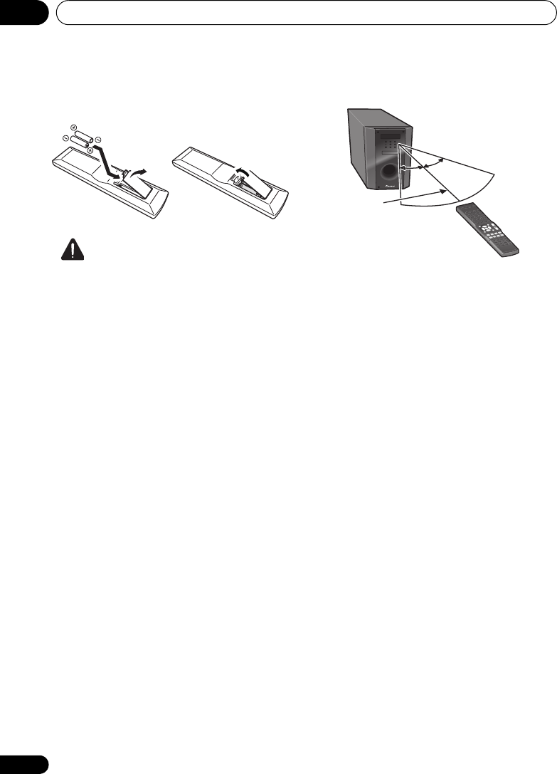
Controls and displays03
50
En
Putting the batteries in the remote
control
CAUTION
Incorrect use of batteries can result in hazards
such as leakage and bursting. Please observe
the following:
• Don’t mix new and old batteries together.
• Don’t use different kinds of battery
together — although they may look similar,
different batteries may have different
voltages.
• Make sure that the plus and minus ends of
each battery match the indications in the
battery compartment.
• Remove batteries from equipment that
isn’t going to be used for a month or more.
• When disposing of used batteries, please
comply with governmental regulations or
environmental public instruction’s rules
that apply in your country/area.
• Do not use or store batteries in direct
sunlight or other excessively hot place,
such as inside a car or near a heater. This
can cause batteries to leak, overheat,
explode or catch fire. It can also reduce the
life or performance of batteries.
Using the remote control
Please keep in mind the following when using
the remote control:
• Make sure that there are no obstacles
between the remote and the remote sensor
on the unit.
• Remote operation may become unreliable
if strong sunlight or fluorescent light is
shining on the unit’s remote sensor.
• Remote controllers for different devices
can interfere with each other. Avoid using
remotes for other equipment located close
to this unit.
• Replace the batteries when you notice a fall
off in the operating range of the remote.
• Use within the operating range in front of
the remote control sensor on the unit, as
shown.
30° 30°
7 m
HTP-710_VYXCN_En.book 50 ページ 2010年8月23日 月曜日 午後6時47分

Getting started 04
51
En
English Deutsch Italiano EspañolFrançais
Nederlands
Chapter 4
Getting started
Automatically setting up for
surround sound (MCACC)
The Auto Multi-Channel Acoustic Calibration
(MCACC) setup measures the acoustic
characteristics of your listening area, taking
into account ambient noise, speaker size and
distance, and tests for both channel delay and
channel level. After you have set up the
microphone provided with your system, the
system uses the information from a series of
test tones to optimize the speaker settings and
equalization for your particular room.
CAUTION
• The test tones used in the Auto MCACC
Setup are output at high volume.
Important
• When using HTP-FS510 and HTP-SB510
models, always use the Auto MCACC setup
function. If this setup is not performed,
various problems may occur, including an
inability to hear screen dialogue, or to hear
sound from the surround channel.
In the event the Auto MCACC setup is not
used, perform the manual Speaker
Setting instead.
• The OSD will not appear if you have
connected using the HDMI output to your
TV. Use composite connections for system
setup.
• The Auto MCACC Setup will overwrite any
existing speaker settings you’ve made.
• Before using the Auto MCACC Setup, the
iPod USB function should not be selected
as an input source.
1 Connect the microphone to the
MCACC
SETUP MIC
jack on the rear panel.
Make sure there are no obstacles between the
speakers and the microphone.
If you have a tripod, use it to place the
microphone so that it’s about ear level at your
normal listening position. Otherwise, place the
microphone at ear level using a table or a chair.
2 Switch on the system and your TV.
Switch the TV input so that it connects to the
system in analog.
TOP
MENU
HOME
MENU
PTY SEARCH
AUDIO
PARAMETER
iPod CTRL
MASTER
VOLUME
TOOLS
MENU
RETURN
ST/MONO
SETUP
ENTER
TV CONTROL
CH
INPUT
INPUT SELECT SOURCE
SYSTEM
SYSTEM
TUNER EDIT
Tripod
Microphone
HTP-710_VYXCN_En.book 51 ページ 2010年8月23日 月曜日 午後6時47分

Getting started04
52
En
3 Press on the remote control,
then press the
SETUP
button.
An on-screen display (OSD) appears on your
TV. Use /// and ENTER on the remote
control to navigate through the screens and
select menu items. Press RETURN to exit the
current menu.
• Press SETUP at any time to exit the System
Setup menu.1
4 Select ‘Auto MCACC’ from the System
Setup menu then press
ENTER
.
2
Try to be as quiet as possible after pressing
ENTER. The system outputs a series of test
tones to establish the ambient noise level.
5 Follow the instructions on-screen.
• Make sure the microphone is connected.
• See below for notes regarding background
noise and other possible interference.
• When using surround back speakers, turn
on the power to the amplifier to which the
surround back speakers are connected,
and adjust the sound level to the desired
level.
6 Wait for the test tones to finish.
• A progress report is displayed on-screen
while the system outputs test tones to
determine the speakers present in your
setup. Try to be as quiet as possible while
it’s doing this.
• For correct speaker settings, do not adjust
the volume during the test tones.
7 Confirm the speaker configuration.
The configuration shown on-screen should
reflect the actual speakers you have.
• With error messages (such as Too much
ambient noise) select RETRY after
checking for ambient noise (see Other
problems when using the Auto MCACC
Setup on page 53).
If the speaker configuration displayed isn’t
correct, use / to select the speaker and
/ to change the setting. When you’re
finished, go to the next step.
If you see an error message (ERR) in the right
side column, there may be a problem with the
speaker connection. If selecting RETRY
doesn’t fix the problem, turn off the power and
check the speaker connections.
Note
1 The screensaver automatically starts after three minutes of inactivity. If you cancel the Auto MCACC Setup at any
time, the system automatically exits and no settings will be made.
2MIC IN blinks when the microphone is not connected to MCACC SETUP MIC.
System Setup
1.Auto MCACC
2.Manual SP Setup
Return
1.Auto MCACC
Now Analyzing
Environment Check
Ambient Noise
Speaker YES/NO
Return
1.Auto MCACC
Check!
OK
Return
10:Next
Front
Center
Surr
Surr. Back
Subwoofer
[ YES ]
[ YES ]
[ YES ]
[YESx2]
[ YES ]
HTP-710_VYXCN_En.book 52 ページ 2010年8月23日 月曜日 午後6時47分

Getting started 04
53
En
English Deutsch Italiano EspañolFrançais
Nederlands
8 Make sure ‘OK’ is selected, then press
ENTER
.
If the screen in step 7 is left untouched for 10
seconds and the ENTER button is not pressed
in step 8, the Auto MCACC setup will start
automatically as shown below.
A progress report is displayed on-screen while
the system outputs more test tones to
determine the optimum system settings for
channel level, speaker distance, and Acoustic
Calibration EQ.
Again, try to be as quiet as possible while this
is happening. It may take 1 to 3 minutes.
9 The Auto MCACC Setup has finished! You
return to the System Setup menu.
• Be sure to disconnect the microphone
from this unit upon completion of the Auto
MCACC setup.
The settings made in the Auto MCACC Setup
should give you excellent surround sound from
your system, but it is also possible to adjust
these settings manually using the System
Setup menu (starting on page 72).1
Other problems when using the Auto
MCACC Setup
If the room environment is not optimal for the
Auto MCACC Setup (too much background
noise, echo off the walls, obstacles blocking
the speakers from the microphone) the final
settings may be incorrect. Check for
household appliances (air conditioner, fridge,
fan, etc.), that may be affecting the
environment and switch them off if necessary.
If there are any instructions showing in the
front panel display, please follow them.
• Some older TVs may interfere with the
operation of the microphone. If this seems
to be happening, switch off the TV when
doing the Auto MCACC Setup.
Note
1 The subwoofer distance setting may be farther than the actual distance from the listening position. This setting
should be accurate (taking delay and room characteristics into account) and generally does not need to be changed.
1.Auto MCACC
Now Analyzing
Surround Analyzing
Speaker System
Speaker Distance
Channel Level
Acoustic Cal EQ
Return
HTP-710_VYXCN_En.book 53 ページ 2010年8月23日 月曜日 午後6時47分

Getting started04
54
En
Basic operation
Procedures for listening to audio from a radio
or connected other component.
1 Turn on the power of the playback
component.
2Press
SYSTEM
to turn on the power of
this system.
3 Select the source you want to playback.
Use the MULTI CONTROL (or INPUT
SELECTOR) buttons.
• Select the type of audio input signal if
required (see below).
4 Start playback of the component you
selected in step 1.
5 Select the listening mode.
Use the listening mode buttons.
6Press
MASTER VOLUME +/–
to adjust the
volume.
Choosing the input signal
On this system, it is possible to switch the
input signals for the different inputs as
described below.1
1 Press on the remote control.
2 Press
SIGNAL SEL
to select the input
signal corresponding to the source
component.
When DIGITAL (C1/O1/O2) or HDMI (H) is
selected and the selected audio input is not
provided, A (analog) is automatically selected.
Each press cycles through the following:
•A – Selects the analog inputs.
•DIGITAL – Selects the digital input. The
coaxial 1 input is selected for C1, and the
optical 1 or 2 audio input is selected for
O1 or O2.
•HDMI – Selects an HDMI signal. H can be
selected for BD/DVD, VIDEO or DVR/VCR
input. For other inputs, HDMI cannot be
selected.2
When set to DIGITAL or HDMI, 2 lights when
a Dolby Digital signal is input, and DTS lights
when a DTS signal is input.
When the HDMI is selected, the A and
DIGITAL indicators are off (see page 44).
SYSTEM
SYSTEM TV CONTROL
CH
VOL
DIMMER
SIGNAL SEL
BD MENU
INPUT
INPUT SELECT SOURCE
TOP
MENU
HOME
MENU
RETURN
ST/MONO
DTV/TV
BASS TRE
SETUP
PTY SEARCH
AUDIO
PARAMETER
iPod CTRL
MASTER
VOLUME
TOOLS
MENU
ENTER
MUTE
TUNER EDIT
Note
1 • This system can only play back Dolby Digital, PCM (32 kHz to 96 kHz) and DTS (including DTS 96 kHz / 24 bit) digital
signal formats. The compatible signals via the HDMI terminals are: Dolby Digital, DTS, SACD (DSD 2 ch), PCM (32
kHz to 192 kHz sampling frequencies), Dolby TrueHD, Dolby Digital Plus, DTS-EXPRESS, DTS-HD Master Audio and
DVD Audio (including 192 kHz). With other digital signal formats, set to A (analog).
• You may get digital noise when a LD or CD player compatible with DTS is playing an analog signal. To prevent noise,
make the proper digital connections (page 33) and set the signal input to C1/O1/O2 (DIGITAL).
• Some DVD players don’t output DTS signals. For more details, refer to the instruction manual supplied with your
DVD player.
2 When the HDMI option in Setting the Audio options on page 69 is set to THRU, the sound will be heard through your
TV, not from this system.
SYSTEM TV CONTROL
CH
VOL
DIMMER
SIGNAL SEL
BD MENU
INPUT
HTP-710_VYXCN_En.book 54 ページ 2010年8月23日 月曜日 午後6時47分

iPod/USB playback 05
55
En
English Deutsch Italiano EspañolFrançais
Nederlands
Chapter 5
iPod/USB playback
Playing an iPod
This system has a dedicated iPod terminal that
will allow you to control playback of audio
content from your iPod using the controls of
this system.1
Important
• When connected to a television using
HDMI output alone, the iPod Top menu will
not be displayed. In this case, use
composite connection instead.
1 Switch on the system and your TV.
See Connecting an iPod/iPhone on page 41.
2 Press the
iPod USB
button to switch the
system to the iPod/USB.
The front panel display shows Loading while
the system verifies the connection and
retrieves data from the iPod.
3Use the
TOP MENU
button to display iPod
Top menu.
When the display shows Top Menu you’re
ready to play music from the iPod.2
•If after pressing iPod the display shows NO
DEVICE, try switching off the system and
reconnecting the iPod to the system.
iPod playback
To navigate songs on your iPod, you can take
advantage of the OSD of your TV connected to
this system.3 You can also control all
operations for music in the front panel display
of this system.
Finding what you want to play
When your iPod is connected to this system,
you can browse songs stored on your iPod by
playlist, artist, album name, song name, genre
or composer, similar to using your iPod
directly.
1Use the
/
buttons to select a category
then press
ENTER
to browse that category.
• To return to the previous level any time,
press RETURN.
Note
1 • This system is compatible with the audio and the video of the iPod nano, iPod fifth generation, iPod classic, iPod
touch and iPhone (iPod shuffle not supported). However, that some of the functions may be restricted for some
models. Note, however, compatibility may vary depending on the software version of your iPod and iPhone. Please be
sure to use the latest available software version.
• iPod and iPhone are licensed for reproduction of non-copyrighted materials or materials the user is legally
permitted to reproduce.
• Features such as the equalizer cannot be controlled using this system, and we recommend switching the equalizer
off before connecting.
• Pioneer cannot under any circumstances accept responsibility for any direct or indirect loss arising from any
inconvenience or loss of recorded material resulting from the iPod failure.
2 The controls of your iPod (excluding iPod touch or iPhone) will be inoperable when connected to this system (Pioneer
shows in the iPod display).
3 • Note that non-roman characters in the title are displayed as .
• This feature is not available for photos or video clips on your iPod.
iPod Top
[ Playlists ]
[ Artists ]
[ Albums ]
[ Songs ]
[ Podcasts ]
[
Genres ]
[ Composers ]
[ Audiobooks ]
[ Shuffle Songs ]
ENTER
HTP-710_VYXCN_En.book 55 ページ 2010年8月23日 月曜日 午後6時47分

iPod/USB playback05
56
En
2Use the
/
buttons to browse the
selected category (e.g., albums).
•Use / to move to previous/next levels.
3 Continue browsing until you arrive at
what you want to play, then press
to start
playback.
1
Navigation through categories on your iPod
looks like this:
Playlists Songs
Artists Albums Songs
Albums Songs
Songs
Podcasts
Genres Artists Albums Songs
Composers Albums Songs
Audiobooks
Shuffle Songs
Tip
• You can play all of the songs in a particular
category by selecting the All item at the top
of each category list. For example, you can
play all the songs by a particular artist.
Basic playback controls
The following table shows the basic playback
controls for your iPod. Press iPod USB to
switch the remote control to the iPod operation
mode.
Note
1 If you’re in the song category, you can also press ENTER to start playback.
Button What it does
Press to start playback.
If you start playback when
something other than a song is
selected, all the songs that fall into
that category will play.
ENTER Press to set the play and pause modes.
Pauses playback, or restarts
playback when paused.
/ Press and hold during playback to
start scanning.
/ Press to skip to previous/next track.
Press repeatedly to switch between
Repeat One, Repeat All and
Repeat Off.
Press repeatedly to switch between
Shuffle Songs, Shuffle Albums
and Shuffle Off.
DISPLAY Press repeatedly to change the song
playback information displayed in
the front panel display.
/When browsing, press to move to
previous/next levels.
/ During Audiobook playback, press
to switch the playback speed: Faster
Normal Slower
TOP
MENU
Press to return to the iPod Top
menu screen.
RETURN Press to return to the previous level.
HTP-710_VYXCN_En.book 56 ページ 2010年8月23日 月曜日 午後6時47分

iPod/USB playback 05
57
En
English Deutsch Italiano EspañolFrançais
Nederlands
Watching photos and video content
To view photos or video on your iPod, since
video control is not possible using this system,
you must use the main controls of your iPod
instead.1
Important
• To play photos or video on your iPod, you
must connect the composite MONITOR
OUT jack and TV. The photos and video
content will not appear if you have
connected using the HDMI output to your
TV.
1 Press
iPod CTRL
to switch to the iPod
controls for photo and video playback.
The system controls will be unavailable while
you are watching iPod videos or browsing
photos.
2 Press
iPod CTRL
again to switch back to
the system controls when you’re done.
About iPod/iPhone
“Made for iPod” and “Made for iPhone” mean
that an electronic accessory has been
designed to connect specifically to iPod, or
iPhone, respectively, and has been certified by
the developer to meet Apple performance
standards. Apple is not responsible for the
operation of this device or its compliance with
safety and regulatory standards.
iPod and iPhone are a trademarks of Apple Inc.,
registered in the U.S. and other countries.
Note
1 • iPod photos and video content can be viewed only when the iPod is connected to the iPod VIDEO input on the front
panel.
· • This feature can only be used with an iPod having video output.
HTP-710_VYXCN_En.book 57 ページ 2010年8月23日 月曜日 午後6時47分

iPod/USB playback05
58
En
Playing a USB device
It is possible to listen to two-channel audio1
using the USB interface on the front of this
system.
Important
• When connected to a television using
HDMI output alone, the USB playback
window of the on-screen display (OSD) will
not be displayed. In this case, use
composite connection instead.
1 Switch on the system and your TV.
2Press
iPod USB
on the remote control to
switch the system to the iPod/USB.
No Device appears in the OSD.
3 Connect your USB device.
2
See Connecting a USB device on page 42.
Loading appears in the OSD as this system
starts recognizing the USB device connected.
After the recognition, a playback screen
appears in the OSD and playback starts
automatically.3
Basic playback controls
The following table shows the basic controls on
the remote for USB playback. Press iPod USB
to switch the remote control to the iPod USB
operation mode.
Note
1 This includes playback of WMA/MP3/MPEG-4 AAC files (except files with copy-protection or restricted playback).
2 • Make sure the system is in standby when disconnecting the USB device.
• Compatible USB devices include external magnetic hard drives, portable flash memory (particularly keydrives) and
digital audio players (MP3 players) of format FAT16/32. It is not possible to connect this system to a personal computer
for USB playback.
• Pioneer cannot guarantee compatibility (operation and/or bus power) with all USB mass storage devices and
assumes no responsibility for any loss of data that may occur when connected to this system.
• With large amounts of data, it may take longer for the system to read the contents of a USB device.
3 • If the file selected cannot be played back, this system automatically skips to the next file playable.
• When the file currently being played back has no title assigned to it, the file name is displayed in the OSD instead;
when neither the album name nor the artist name is present, the row is displayed as a blank space.
• Note that non-roman characters in the playlist are displayed as .
USB
R:Fld S:On
001/004PLAY
Return
Relax Your Body
Kevin Jackson
We are all one
32kbps 0:01
MP3
File/Folder number
File format
Repeat or Shuffle
Song name
Artist name
Album name
Elapsed time
Bit rates
Button What it does
Starts normal playback.
Pauses/unpauses playback.
/ Press to skip to previous/next track.
/ Press and hold during playback to
start scanning.
Press repeatedly to switch between
Repeat Folder, Repeat One and
Repeat All.
Press repeatedly to switch between
Shuffle On and Shuffle Off.
DISPLAY Press repeatedly to change the
song playback information
displayed in the front panel display.
/
/
During playback, press to skip to
previous/next track.
TOP
MENU
Press to return to the menu screen.
RETURN Press to return to the previous level.
HTP-710_VYXCN_En.book 58 ページ 2010年8月23日 月曜日 午後6時47分

iPod/USB playback 05
59
En
English Deutsch Italiano EspañolFrançais
Nederlands
Important
If a USB Error message lights in the display, try
following the points below:
• Switch the system off, then on again.
• Reconnect the USB device with the system
switched off.
• Select another input source (like BD), then
switch back to iPod USB.
• Use a dedicated AC adapter (supplied with
the device) for USB power.
For more information on error messages, see
USB messages on page 88.
If this doesn’t remedy the problem, it is likely
your USB device is incompatible.
Compressed audio compatibility
Note that although most standard bit/
sampling rate combinations for compressed
audio are compatible, some irregularly
encoded files may not play back. The list below
shows compatible formats for compressed
audio files:
•MP3 (MPEG-1/2/2.5 Audio Layer 3) –
Sampling rates: 8 kHz to 48 kHz; Bit rates:
8 kbps to 320 kbps (128 kbps or higher
recommended); File extension: .mp3
•WMA (Windows Media Audio) – Sampling
rates: 32 kHz / 44.1 kHz; Bit rates: 32 kbps
to 192 kbps (128 kbps or higher
recommended); File extension: .wma;
WMA9 Pro and WMA lossless encoding:
No
•AAC (MPEG-4 Advanced Audio Coding) –
Sampling rates: 11.025 kHz to 48 kHz; Bit
rates: 16 kbps to 320 kbps (128 kbps or
higher recommended); File extension:
.m4a; Apple lossless encoding: No
Other compatibility information
• VBR (variable bit rate) MP3/WMA/MPEG-4
AAC playback: Yes1
• DRM (Digital Rights Management)
protection compatible: Yes (DRM-protected
audio files will not play in this system).
About MPEG-4 AAC
Advanced Audio Coding (AAC) is at the core of
the MPEG-4 AAC standard, which incorporates
MPEG-2 AAC, forming the basis of the MPEG-4
audio compression technology. The file format
and extension used depend on the application
used to encode the AAC file. This system plays
back AAC files encoded by iTunes bearing the
extension ‘.m4a’. DRM-protected files will not
play, and files encoded with some versions of
iTunes may not play.
Apple and iTunes are trademarks of Apple Inc.,
registered in the U.S. and other countries.
About WMA
The Windows Media logo printed on the box
indicates that this system can playback
Windows Media Audio content.
WMA is an acronym for Windows Media Audio
and refers to an audio compression technology
developed by Microsoft Corporation. This
system plays back WMA files encoded using
Windows Media® Player bearing the extension
‘.wma’. Note that DRM-protected files will not
play, and files encoded with some versions of
Windows Media® Player may not play.
Windows Media, and the Windows logo are
trademarks or registered trademarks of
Microsoft Corporation in the United States
and/or other countries.
Note
1 Note that in some cases playback time will not be displayed correctly.
HTP-710_VYXCN_En.book 59 ページ 2010年8月23日 月曜日 午後6時47分
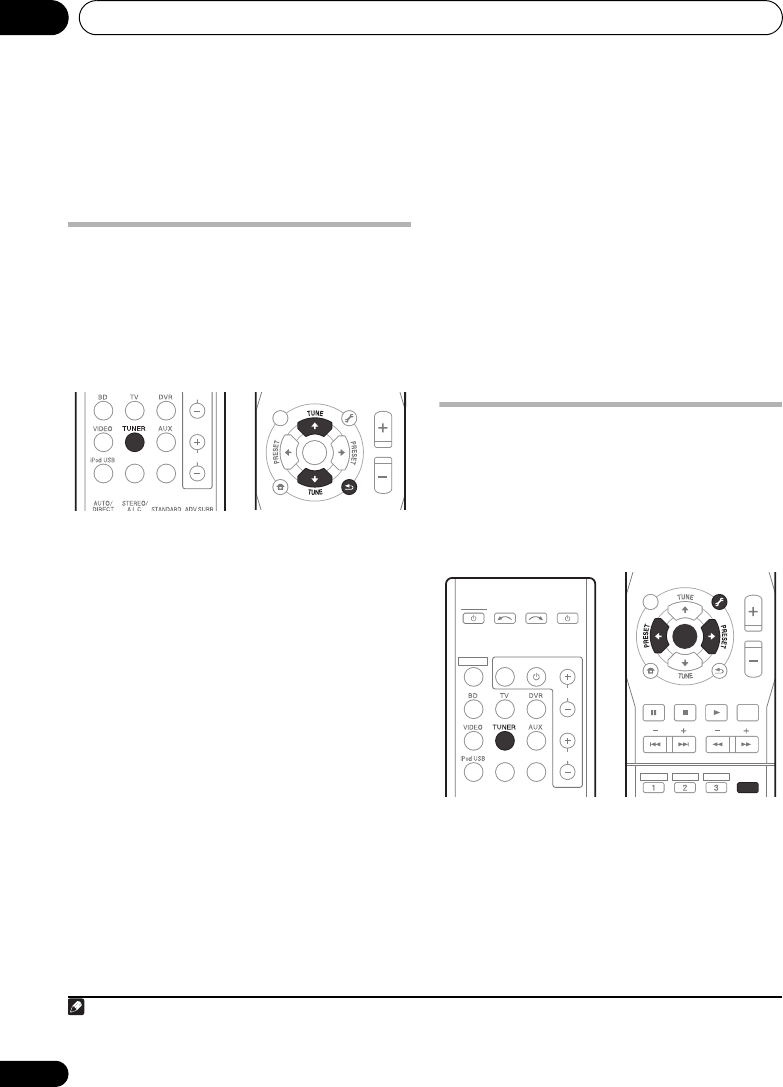
Using the tuner06
60
En
Chapter 6
Using the tuner
Listening to the radio
The following steps show you how to tune in to
FM broadcasts using the automatic (search)
and manual (step) tuning functions. Once you
are tuned to a station you can memorize the
frequency for recall later—see Saving station
presets below for more on how to do this.
1Press
TUNER
to select the tuner.
2 Tune to a station.
There are three ways to do this:
Automatic tuning
To search for stations in the currently
selected band, press and hold TUNE /
(remote control or front panel) for about a
second. The system will start searching for
the next station, stopping when it has
found one. Repeat to search for other
stations.
Manual tuning
To change the frequency one step at a
time, press TUNE /.
High speed tuning
Press and hold TUNE / for high speed
tuning. Release the button at the frequency
you want.
Improving FM stereo sound
If the TUNE or ST indicators don’t light when
tuning to an FM station because the signal is
weak, press the ST/MONO button to select FM
MONO and set the system to the mono
reception mode. This should improve the
sound quality and allow you to enjoy the
broadcast.
Saving station presets
If you often listen to a particular radio station,
it’s convenient to have the system store the
frequency for easy recall whenever you want to
listen to that station. This saves the effort of
manually tuning in each time. This unit can
memorize up to 30 stations.1
1 Tune to a station you want to memorize.
See Listening to the radio above for more on
this.
2 Press
TUNER EDIT
.
The display shows PRESET, then a blinking
MEM and station preset.
TOP
MENU
HOME
MENU
RETURN
ST/MONO
SETUP
PTY SEARCH
AUDIO
PARAMETER
iPod CTRL
MASTER
VOLUME
TOOLS
MENU
ENTER
CH
VOL
DIMMER
SIGNAL SEL
BD MENU
TUNER EDIT
Note
1 If the system is left disconnected from the AC power outlet for over a month, the station memories will be lost and will
have to be reprogrammed.
TOP
MENU
HOME
MENU
RETURN
ST/MONO
DTV/TV
BASS TRE
DISPLAY
SETUP
PTY SEARCH
AUDIO
PARAMETER
iPod CTRL
MASTER
VOLUME
TOOLS
TUNER EDIT
MENU
HDD DVD VCR
ENTER
MUTE
SYSTEM
SYSTEM TV CONTROL
CH
VOL
DIMMER
SIGNAL SEL
BD MENU
INPUT
INPUT SELECT SOURCE
HTP-710_VYXCN_En.book 60 ページ 2010年8月23日 月曜日 午後6時47分

Using the tuner 06
61
En
English Deutsch Italiano EspañolFrançais
Nederlands
3 Press
PRESET /
to select the station
preset you want.
You can also use the number buttons.
4 Press
ENTER
.
After pressing ENTER, the preset number stop
blinking and the system stores the station.
Listening to station presets
You will need to have some presets stored to do
this. See Saving station presets on page 60 if
you haven’t done this already.
• Press
PRESET /
to select the station
preset you want.
• You can also use the number buttons on the
remote control to recall the station preset.
Naming preset stations
For easier identification, you can name all of
your preset stations.
1 Choose the station preset you want to
name.
See Listening to station presets above for how
to do this.
2 Press
TUNER EDIT
twice.
The cursor at the first character position is
blinking on the display.
3 Input the name you want.
Choose a name up to eight characters long.
•Use the PRESET / buttons to select
character position.
•Use the TUNE / buttons to select
characters.
• The name is stored when
ENTER
is pressed.
Tip
• To erase a station name, follow steps 1 and
2, and press ENTER while the display is
blank. Press TUNER EDIT while the display
is blank, to keep the previous name.
• Once you have named a station preset,
press DISPLAY to show the name. When
you want to return to the frequency display,
press DISPLAY several times to show the
frequency.
An introduction to RDS
Radio Data System (RDS) is a system used by
most FM radio stations to provide listeners
with various kinds of information—the name of
the station and the kind of show they’re
broadcasting, for example.
One feature of RDS is that you can search by
type of program. For example, you can search
for a station that’s broadcasting a show with
the program type, JAZZ.
You can search the following program types:1
NEWS – News
AFFAIRS – Current Affairs
INFO – General
Information
SPORT – Sport
EDUCATE – Educational
DRAMA – Radio plays, etc.
CULTURE – National or
regional culture, theater,
etc.
SCIENCE – Science and
technology
VARIED – Usually talk-
based material, such as
quiz shows or interviews.
POP M – Pop music
ROCK M – Rock music
EASY M – Easy listening
LIGHT M – ‘Light’ classical
music
CLASSICS – ‘Serious’
classical music
OTHER M – Music not
fitting above categories
WEATHER – Weather
reports
FINANCE – Stock market
reports, commerce,
trading, etc.
CHILDREN – Programs for
children
SOCIAL – Social affairs
RELIGION – Programs
concerning religion
PHONE IN – Public
expressing their views by
phone
TRAVEL – Holiday-type
travel rather than traffic
announcements
LEISURE – Leisure interests
and hobbies
JAZZ – Jazz
COUNTRY – Country
music
NATION M – Popular
music in a language other
than English
OLDIES – Popular music
from the ’50s and ’60s
FOLK M – Folk music
DOCUMENT –
Documentary
Note
1 In addition, there are three other program types, ALARMTST, ALARM, and NO TYPE. ALARM and ALARMTST are
used for emergency announcements. NO TYPE appears when a program type cannot be found.
HTP-710_VYXCN_En.book 61 ページ 2010年8月23日 月曜日 午後6時47分
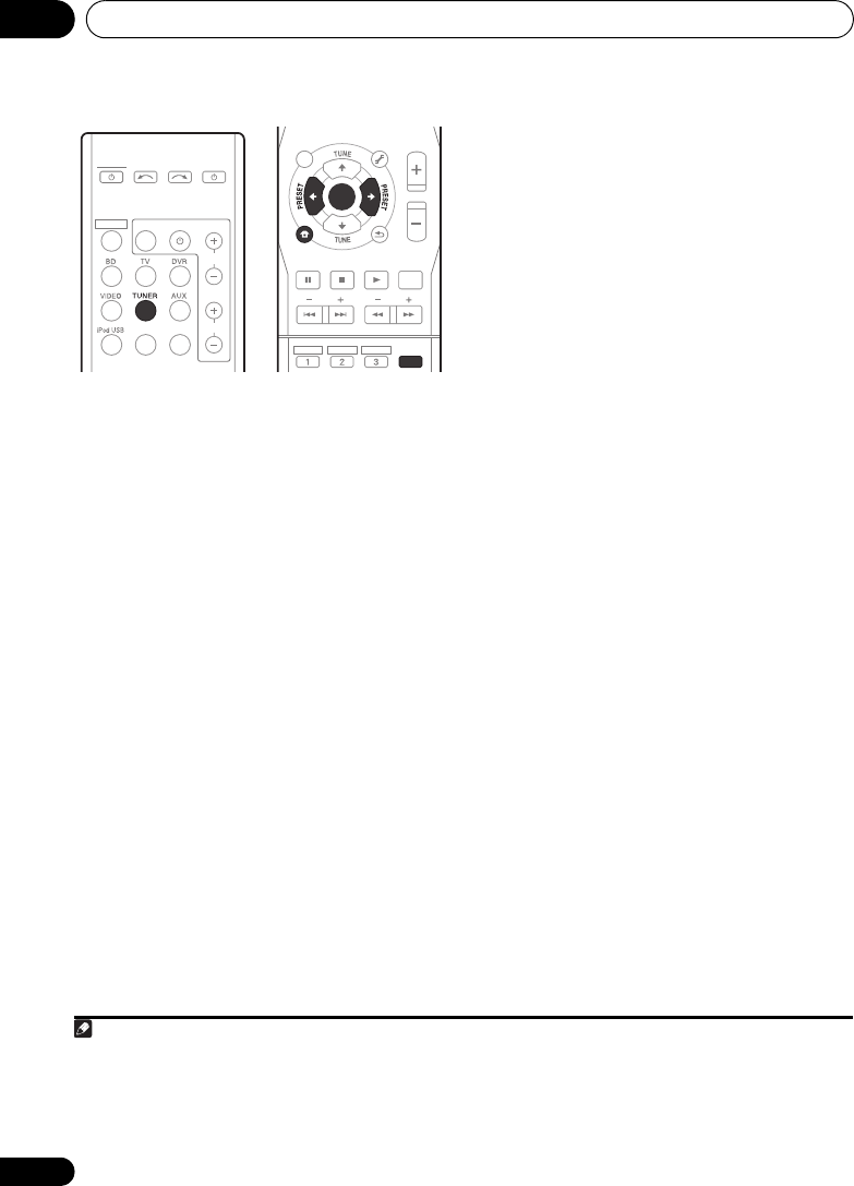
Using the tuner06
62
En
Searching for RDS programs
You can search for a program type listed above.
1Press
TUNER
.
2Press
PTY SEARCH
.
SEARCH shows in the display.
3Press
PRESET /
to select the program
type you want to hear.
4Press
ENTER
to search for the program
type.
The system starts searching through the
station presets for a match, stopping when it
was found one. Repeat to search for other
stations.
If NO PTY is displayed it means the tuner
couldn’t find that program type at the time of
the search.1
Displaying RDS information
Use the DISPLAY button to display the
different types of RDS information available.2
• Press
DISPLAY
for RDS information.
Each press changes the display as follows:
•Listening mode
•Master volume
• Radio Text (RT) – Messages sent by the
radio station. For example, a talk radio
station may provide a phone number as RT.
• Program Service Name (PS) – The name of
the radio station.
•Program Type (PTY) – This indicates the
kind of program currently being broadcast.
• Current tuner frequency (FREQ)
Note
1 RDS searches station presets only. If no stations have been preset, or if the program type could not be found among
the station presets NO PTY is displayed. FINISH means the search is complete.
TOP
MENU
HOME
MENU
RETURN
ST/MONO
DTV/TV
BASS TRE
DISPLAY
SETUP
PTY SEARCH
AUDIO
PARAMETER
iPod CTRL
MASTER
VOLUME
TOOLS
TUNER EDIT
MENU
HDD DVD VCR
ENTER
MUTE
SYSTEM
SYSTEM TV CONTROL
CH
VOL
DIMMER
SIGNAL SEL
BD MENU
INPUT
INPUT SELECT SOURCE
2 • If any noise is picked up while displaying the RT scroll, some characters may be displayed incorrectly.
• If you see NO TEXT in the RT display, it means no RT data is sent from the broadcast station. The display will
automatically switch to the PS data display (if no PS data, NO NAME is displayed).
• In the PTY display, NO PTY may be shown.
HTP-710_VYXCN_En.book 62 ページ 2010年8月23日 月曜日 午後6時47分

Listening to your system 07
63
En
English Deutsch Italiano EspañolFrançais
Nederlands
Chapter 7
Listening to your system
Important
• The listening modes and many features
described in this section may not be
available depending on the current source,
settings and status of the system.
Selecting Listening mode
Various listening modes are available for
enjoyment of diverse sound effects and for
sound field correction according to your
preference.
The best listening mode may vary, depending
on the model. In order to ascertain the best
settings for your listening conditions, use of
the Auto MCACC function is recommended.
• HTP-710/HTP-610/HTP-SB510 model
Select one listening mode from the surround
sound mode. See Listening in surround sound
below.
• HTP-FS510 model
Select one listening mode from the Front Stage
Surround Advance mode. See Using Front
Stage Surround Advance on page 65.
• When optional speakers are connected,
select one listening mode from the
surround sound mode. See Listening in
surround sound below.
Auto playback
The simplest, most direct listening option is
the Auto Surround feature. With this, the
system automatically detects what kind of
source you’re playing and selects
multichannel or stereo playback as
necessary.1
• While listening to a source, press
AUTO/
DIRECT
2
for auto playback of a source.
Press repeatedly until AUTO SURROUND
shows briefly in the display (it will then show
the decoding or playback format). Check the
digital format indicators in the display to see
how the source is being processed.
Listening in surround sound
For HTP-710/HTP-610/HTP-SB510:
Using this system, you can listen to any source
in surround sound. However, the options
available will depend on your speaker setup
and the type of source you’re listening to.
The following modes provide basic surround
sound for stereo and multichannel sources.
Note
1 Stereo surround (matrix) formats are decoded accordingly using NEO:6 CINEMA or DOLBY PLII MOVIE (see
Listening in surround sound above for more on these decoding formats).
2 For more options using this button, see Using Stream Direct on page 65.
HTP-710_VYXCN_En.book 63 ページ 2010年8月23日 月曜日 午後6時47分

Listening to your system07
64
En
• While listening to a source, press
STANDARD
.
If the source is Dolby Digital, DTS, or Dolby
Surround encoded, the proper decoding
format will automatically be selected and
shows in the display.
With two channel sources, you can select from:
•DOLBY PLII MOVIE – Up to 5.1 channel
sound, especially suited to movie sources
•DOLBY PLII MUSIC1 – Up to 5.1 channel
sound, especially suited to music sources
•DOLBY PLII GAME – Up to 5.1 channel
sound, especially suited for video games
•NEO:6 CINEMA – Up to 5.1 channel sound,
especially suited to movie sources
•NEO:6 MUSIC – Up to 5.1 channel sound,
especially suited to music sources2
•DOLBY PRO LOGIC – 4.1 channel
surround sound
Using the Advanced surround effects
The Advanced surround feature creates a
variety of surround effects. Try different modes
with various soundtracks to see which you like.
•Press
ADV SURR
repeatedly to select a
listening mode.
•ACTION – Designed for action movies with
dynamic soundtracks.
•DRAMA – Designed for movies with lots of
dialog.
•ENT.SHOW – Suitable for musical sources.
•ADVANCED GAME – Suitable for video
games.
•SPORTS – Suitable for sports programs.
•CLASSICAL – Gives a large concert hall-
type sound.
•ROCK/POP – Creates a live concert sound
for rock and/or pop music.
•UNPLUGGED – Suitable for acoustic
music sources.
•EXT.STEREO – Gives multichannel sound
to a stereo source, using all of your
speakers.
Listening in stereo
When you select STEREO you will hear the
source through just the front left and right
speakers (and possibly your subwoofer
depending on your speaker settings). Dolby
Digital and DTS multichannel sources are
downmixed to stereo.
In the Auto level control stereo mode (A.L.C.),
this unit equalizes playback sound levels if
each sound level varies with the music source
recorded in a portable audio player.
• While listening to a source, press
STEREO/A.L.C.
for stereo playback.
Press repeatedly to switch between:
•STEREO – The audio is heard with your
surround settings and you can still use the
Midnight, Phase Control, Sound Retriever
and Tone functions.
•A.L.C. – Listening in Auto level control
stereo mode.
•F.S.S.ADVANCE – See Using Front Stage
Surround Advance on page 65 for more on
this.
Note
1 When listening to 2-channel sources in DOLBY PLII MUSIC mode, there are three further parameters you can adjust:
C.WIDTH, DIMEN., and PNRM.. See Setting the Audio options on page 69 to adjust them.
2 When listening to 2-channel sources in NEO:6 CINEMA or NEO:6 MUSIC mode, you can also adjust the C.IMG effect
(see Setting the Audio options on page 69).
HTP-710_VYXCN_En.book 64 ページ 2010年8月23日 月曜日 午後6時47分

Listening to your system 07
65
En
English Deutsch Italiano EspañolFrançais
Nederlands
Using Front Stage Surround
Advance
The Front Stage Surround Advance function
allows you to create natural surround sound
effects using just the front speakers and the
subwoofer.
• While listening to a source, press
STEREO/A.L.C.
to select Front Stage
Surround Advance modes.
•STEREO – See Listening in stereo on
page 64 for more on this.
•A.L.C. – See Listening in stereo on page 64
for more on this.
•F.S.S.ADVANCE – Use to provide a rich
surround sound effect directed to the
center of where the front left and right
speakers sound projection area converges.
Using Stream Direct
Use the Stream Direct modes when you want
to hear the truest possible reproduction of a
source. All unnecessary signal processing is
bypassed.
• While listening to a source, press
AUTO/
DIRECT
to select Stream Direct mode.
•AUTO SURROUND – See Auto playback on
page 63.
•DIRECT – Sources are heard according to
the settings made in the Surround Setup
(speaker setting, channel level, speaker
distance), as well as with dual mono
settings.1 You will hear sources according
to the number of channels in the signal.
•PURE DIRECT – Analog and PCM sources
are heard without any digital processing.2
Using the Sound Retriever
When audio data is removed during the
compression process, sound quality often
suffers from an uneven sound image. The
Sound Retriever feature employs new DSP
technology that helps bring CD quality sound
back to compressed 2-channel audio by
restoring sound pressure and smoothing
jagged artifacts left over after compression.3
• Press , then press
S.RETRIEVER
to switch the sound retriever on or off.
F.S.S.ADVANCE
position
Front left
speaker Front right
speaker
Note
1In the DIRECT mode, Phase Control, Acoustic Calibration EQ, Sound Delay, Auto Delay, LFE Attenuate and Center
image functions are available.
2 There are cases where a brief noise is heard before playback of sources other than PCM. Please select AUTO
SURROUND or DIRECT if this is a problem.
3 The Sound Retriever is only applicable to 2-channel sources.
DISPLAY
CH
CH
EQ
PHASESB CH
CH SELECT
SLEEP
MIDNGIHT
S.RETRIEVER
HDD DVD VCR
SHIFT
SYSTEM TV CONTROL
CH
INPUT
HTP-710_VYXCN_En.book 65 ページ 2010年8月23日 月曜日 午後6時47分

Listening to your system 07
67
En
English Deutsch Italiano EspañolFrançais
Nederlands
Functions when surround back
speakers are connected
For HTP-710/HTP-610 (In the case of the HTP-
FS510 and HTP-SB510, it may be necessary to
connect the optional speaker systems as well.):
When surround back speakers are connected
to a surround back amplifier, 7.1 ch surround
sound is possible. In this case, it is possible to
select a listening mode and make other
settings supported by 7.1 ch playback.1
See also Using surround back channel
processing on page 68.
Surround sound mode
With two channel sources, you can select from:
•DOLBY PLIIx MOVIE – Up to 7.1 channel
sound, especially suited to movie sources
•DOLBY PLIIx MUSIC – Up to 7.1 channel
sound, especially suited to music sources2
•DOLBY PLIIx GAME – Up to 7.1 channel
sound, especially suited to video games
•NEO:6 CINEMA – 6.1 channel sound,
especially suited to movie sources
•NEO:6 MUSIC – 6.1 channel sound,
especially suited to music sources3
•DOLBY PRO LOGIC – 4.1 channel
surround sound (sound from the surround
speakers is mono)
With multichannel sources, if you have
connected surround back speaker(s) and have
selected SB ON, you can select (according to
format):
•DOLBY PLIIx MOVIE – See above (only
available when you’re using two surround
back speakers)
•DOLBY PLIIx MUSIC – See above
•DOLBY DIGITAL EX – Creates surround
back channel sound for 5.1 channel
sources and provides pure decoding for
6.1 channel sources (like Dolby Digital
Surround EX)
•DTS-ES – Allows you to hear 6.1 channel
playback with DTS-ES encoded sources
•DTS NEO:6 – Allows you to hear 6.1
channel playback with DTS encoded
sources
Note
1 • If surround back channel processing (page 68) is switched off, or the surround back speakers are set to NO, DOLBY
PLIIx becomes DOLBY PLII (5.1 channel sound).
• In modes that give 6.1 channel sound, the same signal is heard from both surround back speakers.
2 When listening to 2-channel sources in DOLBY PLIIx MUSIC mode, there are three further parameters you can adjust:
C.WIDTH, DIMEN., and PNRM.. See Setting the Audio options on page 69 to adjust them.
3 When listening to 2-channel sources in NEO:6 CINEMA or NEO:6 MUSIC mode, you can also adjust the C.IMG effect
(see Setting the Audio options on page 69).
HTP-710_VYXCN_En.book 67 ページ 2010年8月23日 月曜日 午後6時47分
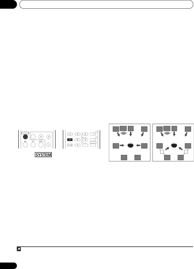
Listening to your system07
68
En
Using surround back channel
processing
• Default setting: SB ON
You can have the system automatically use 6.1
or 7.1 decoding for 6.1 encoded sources (for
example, Dolby Digital EX or DTS-ES), or you
can choose to always use 6.1 or 7.1 decoding
(for example, with 5.1 encoded material).
With
5.1 encoded sources, a surround back channel
will be generated, but the material may sound
better in the 5.1 format for which it was originally
encoded (in which case, you can simply switch
surround back channel processing off).
• With a 7.1-channel surround system, audio
signals that have undergone matrix
decoding processing through surround
back channel processing to which the Up
Mix function is added are output from the
surround back speakers.
• Press , then press SB CH
repeatedly to cycle the surround back
channel options.
Each press cycles through the options as follows:
•SB ON – Matrix decoding processing for
generating the surround back component
from the surround component is turned on.
•SB AUTO – Matrix decoding processing for
generating the surround back component
from the surround component is switched
automatically. Matrix decoding processing
is only performed when surround back
channel signals are detected in the input
signals.
•
SB
OFF
– Matrix decoding processing for
generating the surround back component
from the surround component is turned off.
Setting the Up Mix function
In a 7.1-channel surround system with
surround speakers placed directly at the sides
of the listening position, the surround sound of
5.1-channel sources is heard from the side.
The Up Mix function mixes the sound of the
surround speakers with the surround back
speakers so that the surround sound is heard
from diagonally to the rear as it should be.1
• Using the Up Mix function is effective when
the speakers in the 7.1-channel surround
system are set up as recommended in the
example below.
• Depending on the positions of the speakers
and the sound source, in some cases it
may not be possible to achieve good
results. In this case, set the setting to OFF.
1 Switch the system into standby.
2 While holding down the PRESET + on the
front panel, and hold the
STANDBY/ON for
about two seconds.
UP MIX: OFF appears and the Up Mix function
turns off. If you want to turn this function on,
perform steps 1 and 2 again.
•When set to ON, the UP MIX indicator on
the front panel lights.
SYSTEM TV CONTROL
CH
INPUT
CH
CH
EQ
PHASESB CH
CH SELECT
SLEEP
ENTER
MIDNGIHT
S.RETRIEVER
SHIFT
Note
1 • Set to ON regardless of this setting when playing DTS-HD signals.
• May automatically be set to OFF even when set to ON, depending on the input signal and listening mode.
C
SW
FL FR
SLSR
SBL SBR SBL SBR
C
SW
FL FR
SLSR
Up Mix OFF Up Mix ON
HTP-710_VYXCN_En.book 68 ページ 2010年8月23日 月曜日 午後6時47分
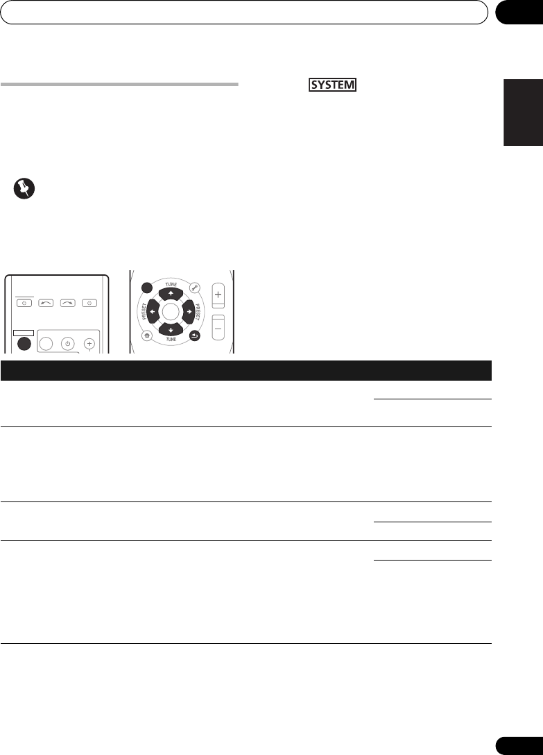
Listening to your system 07
69
En
English Deutsch Italiano EspañolFrançais
Nederlands
Setting the Audio options
There are a number of additional sound
settings you can make using the AUDIO
PARAMETER menu. The defaults, if not stated,
are listed in bold.
Important
• Note that if a setting doesn’t appear in the
AUDIO PARAMETER menu, it is
unavailable due to the current source,
settings and status of the system.
1 Press on the remote control,
then press
AUDIO PARAMETER
button.
2Use
/
to select the setting you want to
adjust.
Depending on the current status/mode of the
system, certain options may not be able to be
selected. Check the table below for notes on
this.
3Use
/
to set it as necessary.
See the table below for the options available for
each setting.
4Press
RETURN
to confirm and exit the
menu.
TOP
MENU
HOME
MENU
RETURN
ST/MONO
SETUP
PTY SEARCH
AUDIO
PARAMETER
iPod CTRL
MASTER
VOLUME
TOOLS
MENU
ENTER
SYSTEM
SYSTEM TV CONTROL
INPUT
INPUT SELECT SOURCE
Setting What it does Option(s)
EQ
(Acoustic
Calibration EQ)
Switches on/off the effect of Acoustic Calibration EQ. ON
OFF
S.DELAY
(Sound Delay)
Some monitors have a slight delay when showing
video, so the soundtrack will be slightly out of sync
with the picture. By adding a bit of delay, you can
adjust the sound to match the presentation of the
video.
0.0 to 9.0 (frames)
1 second = 25 frames
(PAL)
Default: 0.0
MIDNIGHTaAllows you to hear effective surround sound of movies
at low volumes.
MID OFF
MIDNIGHT
S.RTVb
(Sound Retriever)
When audio data is removed during the WMA/MP3c
compression process, sound quality often suffers from
an uneven sound image. The Sound Retriever feature
employs new DSP technology that helps bring CD
quality sound back to compressed 2-channel audio by
restoring sound pressure and smoothing jagged
artifacts left over after compression.
OFF
ON
HTP-710_VYXCN_En.book 69 ページ 2010年8月23日 月曜日 午後6時47分

Listening to your system 07
71
En
English Deutsch Italiano EspañolFrançais
Nederlands
a. You can change the MIDNIGHT option at any time by using MIDNIGHT button.
b. You can change the Sound Retriever feature at any time by using S.RETRIEVER button.
c. WMA and MP3 playback available only via iPod/USB input.
d. This setting works only with dual mono encoded Dolby Digital and DTS soundtracks.
e. The initial set AUTO is only available for Dolby TrueHD signals. Select MAX or MID for signals other than
Dolby TrueHD.
f. This feature is only available when the connected display supports the automatic audio/video synchronizing
capability (‘lip-sync’) for HDMI. If you find the automatically set delay time unsuitable, set A.DLY to OFF and
adjust the delay time manually. For more details about the lip-sync feature of your display, contact the
manufacturer directly.
g. Only available with 2-channel sources in DOLBY PLII MUSIC mode.
h. Only when listening to 2-channel sources in NEO:6 CINEMA and NEO:6 MUSIC mode.
PNRM.g
(Panorama)
Extends the front stereo image to include surround
speakers for a ‘wraparound’ effect.
OFF
ON
C.IMGh
(Center image)
(Applicable only
when using a center
speaker)
Adjust the center image to create a wider stereo effect
with vocals. Adjust the effect from 0 (all center
channel sent to front right and left speakers) to 10
(center channel sent to the center speaker only).
0 to 10
Default: 3
(NEO:6 MUSIC),
10 (NEO:6 CINEMA)
Setting What it does Option(s)
HTP-710_VYXCN_En.book 71 ページ 2010年8月23日 月曜日 午後6時47分

The System Setup menu08
72
En
Chapter 8
The System Setup menu
Using the System Setup menu
The following section shows you how to make
detailed settings to specify how you’re using
the system, and also explains how to fine-tune
individual speaker system settings to your
liking.
Important
• The OSD will not appear if you have
connected using the HDMI output to your
TV. Use composite connections for system
setup.
1 Switch on the system and your TV.
Use the SYSTEM button to switch on.
Switch the TV input so that it connects to the
system in analog.
2 Press on the remote control,
then press the
SETUP
button.
1
An on-screen display (OSD) appears on your
TV. Use /// and ENTER on the remote
control to navigate through the screens and
select menu items. Press RETURN to confirm
and exit the current menu.
3 Select the setting you want to adjust.
•Auto MCACC – This is a quick and
effective automatic surround setup (see
Automatically setting up for surround
sound (MCACC) on page 51).
•Manual SP Setup – Specify the number,
distance and overall balance of the
speakers you’ve connected (see Manual
speaker setup below).
Manual speaker setup
These settings are designed to fine-tune your
system, but if you’re satisfied with the settings
made in Automatically setting up for surround
sound (MCACC) on page 51, it isn’t necessary
to make all of these settings.
CAUTION
• The test tones used in the System Setup
are output at high volume.
Note
1 • You can’t use the System Setup menu when the iPod/USB input is selected.
• Press SETUP at any time to exit the System Setup menu.
TOP
MENU
HOME
MENU
PTY SEARCH
AUDIO
PARAMETER
iPod CTRL
MASTER
VOLUME
TOOLS
MENU
RETURN
ST/MONO
SETUP
ENTER
TV CONTROL
CH
INPUT
INPUT SELECT SOURCE
SYSTEM
SYSTEM
TUNER EDIT
System Setup
1.Auto MCACC
2.Manual SP Setup
Return
HTP-710_VYXCN_En.book 72 ページ 2010年8月23日 月曜日 午後6時47分

The System Setup menu 08
73
En
English Deutsch Italiano EspañolFrançais
Nederlands
1 Select ‘Manual SP Setup’ then press
ENTER
.
2 Select the setting you want to adjust.
If you are doing this for the first time, you may
want to adjust these settings in order:
•Speaker Setting – Specify the number of
speakers you’ve connected (see below).
•Channel Level – Adjust the overall balance
of your speaker system (see below).
•Speaker Distance – Specify the distance
of your speakers from the listening position
(see page 74).
3 Make the adjustments necessary for each
setting, pressing
RETURN
to confirm after
each screen.
Speaker Setting
Use this setting to specify your speaker
configuration (number of speakers). It is a
good idea to make sure that the settings made
in Automatically setting up for surround sound
(MCACC) on page 51 are correct.
1 Select ‘Speaker Setting’ from the Manual
SP Setup menu.
2 Choose the set of speakers that you want
to set then select a speaker setting.
Use / to select the number of each of the
following speakers:
•Front – This setting cannot be changed,
since it is already optimized for this unit.
•Center – Select SMALL if you connect a
center speaker. If you didn’t connect a
center speaker, choose NO (the center
channel is sent to the other speakers).
•Surr – Select SMALL if you connect
surround speakers. If you didn’t connect
surround speakers choose NO (the sound
of the surround channels is sent to the
other speakers).
•Surr. Back – Select the number of
surround back speakers you have (one, two
or none).1 If you didn’t connect surround
back speakers choose NO.
•Subwoofer – This setting cannot be
changed, since it is already optimized for
this unit.
3 When you’re finished, press
RETURN
.
You return to the Manual SP Setup menu.
Tip
For HTP-FS510:
If optional speaker systems are not connected,
set Center and Surr to NO.
For HTP-SB510:
If optional speaker systems are not connected,
set Surr to NO.
Channel Level
Using the channel level settings, you can
adjust the overall balance of your speaker
system, an important factor when setting up a
home theater system.
System Setup
1.Auto MCACC
2.Manual SP Setup
Return
2.Manual SP Setup
Return
a.Speaker Setting
b.Channel Level
c.Speaker Distance
2.Manual SP Setup
Return
a.Speaker Setting
b.Channel Level
c.Speaker Distance
2a.Speaker Setting
Front
Center
Surr
Surr. Back
Subwoofer:
Return
[ SMALL ]
[ SMALL ]
[ NO ]
YES
SMALL
Note
1 • If the surround speakers are set to NO, the surround back speakers will automatically be set to NO.
• If you select one surround back speaker only, make sure that additional amplifier is hooked up to the PRE OUT
SURROUND BACK L (Single) terminal.
HTP-710_VYXCN_En.book 73 ページ 2010年8月23日 月曜日 午後6時47分

The System Setup menu08
74
En
1 Select ‘Channel Level’ from the Manual SP
Setup menu.
2 Select a setup option.
•Manual – Move the test tone manually
from speaker to speaker and adjust
individual channel levels.
•Auto – Adjust channel levels as the test
tone moves from speaker to speaker
automatically.
3 Confirm your selected setup option.
The test tones will start after you press ENTER.
After the volume increases to the reference
level, test tones will be output.
4 Adjust the level of each channel using
/
.
If you selected Manual, use / to switch
speakers. The Auto setup will output test tones
in the order shown on-screen:
Adjust the level of each speaker as the test tone
is emitted.1
5 When you’re finished, press
RETURN
.
You return to the Manual SP Setup menu.
Tip
• You can change the channel levels at any
time by press , then press CH
SELECT and +/– on the remote control. You
can also press CH SELECT and use / to
select the channel, and then use / to
adjust the channel levels.
Speaker Distance
For good sound depth and separation from
your system, you need to specify the distance
of your speakers from the listening position.
The system can then add the proper delay
needed for effective surround sound.
1 Select ‘Speaker Distance’ from the
Manual SP Setup menu.
2 Adjust the distance of each speaker using
/
.
You can adjust the distance of each speaker in
0.1 m increments.
3 When you’re finished, press RETURN.
You return to the Manual SP Setup menu.
Note
1 • If you are using a Sound Pressure Level (SPL) meter, take the readings from your main listening position and adjust
the level of each speaker to 75 dB SPL (C-weighting/slow reading).
• The subwoofer test tone is output at low volumes. You may need to adjust the level after testing with an actual
soundtrack.
2.Manual SP Setup
Return
a.Speaker Setting
b.Channel Level
c.Speaker Distance
2b.Channel Level
Test Tone Manual
ENTER:NextReturn
2b.Channel Level
Test Tone [ Manual ]
Please Wait . . .20
Caution
Loud test tones
will be output.
Return
2b.Channel Level
Front L
Center
Front R
Surround R
Surr. Back R
Surr. Back L
Surround L
Subwoofer
Return
[ 0dB]
[ 0dB]
[ 0dB]
[ ––– ]
[ ––– ]
[ 0dB]
[ 0dB]
0dB
2.Manual SP Setup
Return
a.Speaker Setting
b.Channel Level
c.Speaker Distance
2c.Speaker Distance
Front L
Center
Front R
Surround R
Surr. Back R
Surr. Back L
Surround L
Subwoofer
Return
3.0 m
[ 3.0 m ]
[ 3.0 m ]
[ 3.0 m ]
[ –––– ]
[ –––– ]
[ 3.0 m ]
[ 3.0 m ]
HTP-710_VYXCN_En.book 74 ページ 2010年8月23日 月曜日 午後6時47分

Controlling the rest of your system09
76
En
Controls for TVs
This remote control can control components after entering the proper codes or teaching the
system the commands (see Controlling the rest of your system on page 75 for more on this). Use
the MULTI CONTROL buttons to select the component
•The TV CONTROL buttons on the remote control are dedicated to control the TV assigned to
the TV button.
Button(s) Function Components
TV CONTROL
Switches the DTV on or off. DTV
Switches the TV or CATV between standby and on. Cable TV/Satellite TV/TV
TV CONTROL
INPUT
Switches the TV input. (Not possible with all models.) TV
TV CONTROL
CH +/–
Selects channels. Cable TV/Satellite TV/TV/
DTV
TV CONTROL
VOL +/–
Adjust the TV volume. Cable TV/Satellite TV/TV/
DTV
SOURCE Press to switch the component assigned to the TV
button on or off.
Cable TV/Satellite TV/TV/
DTV
DTV/TV Switches between the DTV and analog TV input modes
for Pioneer TVs.
DTV/TV
TOP MENU Switches TEXT ON/OFF for TVs. TV
HOME MENU Use as the GUIDE button for navigating. Cable TV/Satellite TV/TV/
DTV
RETURN Use to select closed captioning with DTV. DTV
Number
buttons
Use to select a specific TV channel. Cable TV/Satellite TV/TV/
DTV
+10 button Use to add a decimal points when selecting TV
channels.
DTV
ENTER Use to enter a channel. Cable TV/Satellite TV/TV/
DTV
MENU Press to display the DTV menu. DTV
Select the menu screen. Cable TV/Satellite TV/TV
&
ENTER
Press to select or adjust and navigate items on the
menu screen.
Cable TV/Satellite TV/TV/
DTV
CH +/– Selects channels. Cable TV/Satellite TV/TV/
DTV
HTP-710_VYXCN_En.book 76 ページ 2010年8月23日 月曜日 午後6時47分

Controlling the rest of your system 09
77
En
English Deutsch Italiano EspañolFrançais
Nederlands
Controls for other components
This remote control can control these components after entering the proper codes or teaching the
system the commands (see Controlling the rest of your system on page 75 for more on this). Use
the MULTI CONTROL buttons to select the component.
Button(s) Function Components
SOURCE Press to switch the component between standby and on. BD/DVD player, DVR, VCR
Press to return to the start of the current track.
Repeated presses skips to the start of previous tracks.
BD/DVD player, DVR, VCR
Press to advance to the start of the next track.
Repeated presses skips to the start of following tracks.
BD/DVD player, DVR, VCR
Pause playback or recording. BD/DVD player, DVR, VCR
Start playback. BD/DVD player, DVR, VCR
Hold down for fast forward playback. BD/DVD player, DVR, VCR
Hold down for fast reverse playback. BD/DVD player, DVR, VCR
Stops playback (on some models, pressing this when the
disc is already stopped will cause the disc tray to open).
BD/DVD player, DVR, VCR
Number
buttons
Directly access tracks on a program source. VCR
Use to enter a title/chapter/track number. BD/DVD player, DVR
+10 button Selects tracks higher than 10. (For example, press +10
then 3 to select track 13.)
BD/DVD player, DVR
ENTER Use as the ENTER button. BD/DVD player
Displays the DISC NAVI screen for DVD recorder. DVR
DISPLAY Press to display information. BD/DVD player, DVR
TOP MENU Displays the disc ‘top’ menu of a BD/DVD player. BD/DVD player, DVR
MENU Displays menus for the current BD/DVD player or DVD
recorder you are using.
BD/DVD player, DVR
,
ENTER &
RETURN
Navigates BD/DVD menu/options. BD/DVD player, DVR
HOME
MENU
Displays the HOME MENU. BD/DVD player, DVR
CH +/– Selects channels. DVR, VCR
HDD
(SHIFT + 1)
Switches to the hard disk controls when using an HDD/
DVD recorder.
HDD/DVD/VCR recorder
HTP-710_VYXCN_En.book 77 ページ 2010年8月23日 月曜日 午後6時47分

Controlling the rest of your system09
78
En
DVD
(SHIFT + 2)
Switches to the DVD controls when using an HDD/DVD
recorder.
HDD/DVD/VCR recorder
VCR
(SHIFT + 3)
Switches to the VCR controls when using an HDD/DVD/
VCR recorder.
HDD/DVD/VCR recorder
Button(s) Function Components
HTP-710_VYXCN_En.book 78 ページ 2010年8月23日 月曜日 午後6時47分

Controlling the rest of your system 09
79
En
English Deutsch Italiano EspañolFrançais
Nederlands
BD/DVD/DVR
Manufacturer Code
AEG 2093
Aiwa 2054
Akai 2001
Akura 2091
Alba 2027, 2038, 2048
Amitech 2093
AMW 2094
Awa 2094
Bang & Olufsen 2096
Bellagio 2094
Best Buy 2090
Brainwave 2093
Brandt 2017, 2044
Bush 2027, 2048, 2082,
2089
Cambridge Audio 2085
CAT 2087, 2088
Centrum 2088
CGV 2085, 2093
Cinetec 2094
Clatronic 2089
Coby 2095
Conia 2082
Continental Edison 2094
Crown 2093
C-Tech 2086
CyberHome 2008, 2037
Daenyx 2094
Daewoo 2035, 2059, 2093,
2094
Daewoo International
2094
Dalton 2092
Dansai 2084, 2093
Daytek 2010, 2033, 2094
Dayton 2094
DEC 2089
Decca 2093
Denon 2066, 2068
Denver 2069, 2089, 2091,
2095
Denzel 2083
Diamond 2085, 2086
DK Digital 2034
Dmtech 2000
Dual 2083
DVX 2086
Easy Home 2090
Eclipse 2085
Electrohome 2093
Elin 2093
Elta 2047, 2093
Enzer 2083
Finlux 2085, 2093
Gericom 2050
Global Solutions 2086
Global Sphere 2086
Goodmans 2027, 2070,
2089
Graetz 2083
Grundig 2053
Grunkel 2093
H&B 2089
Haaz 2085, 2086
HiMAX 2090
Hitachi 2015, 2083, 2090
Innovation 2002
JVC 2024, 2041, 2057
Kansai 2095
Kennex 2093
Kenwood 2051
KeyPlug 2093
Kiiro 2093
Kingavon 2089
Kiss 2083
Koda 2089
KXD 2090
Lawson 2086
Lecson 2084
Lenco 2089, 2093
LG 2016, 2020, 2040, 2043,
2065, 2076
Life 2002
Lifetec 2002
Limit 2086
Loewe 2056
LogicLab 2086
Magnavox 2089
Majestic 2095
Marantz 2062
Marquant 2093
Matsui 2044
Mecotek 2093
Medion 2002
MiCO 2085
Micromaxx 2002
Microstar 2002
Minoka 2093
Mizuda 2089, 2090
Monyka 2083
Mustek 2006
Mx Onda 2085
Naiko 2093
Neufunk 2083
Nevir 2093
NU-TEC 2082
Onkyo 2072
Optim 2084
Optimus 2004
Orava 2089
Orbit 2094
Orion 2061
P&B 2089
Pacific 2086
Panasonic 2018, 2019,
2026, 2032, 2036, 2075
Philips 2005, 2011, 2022,
2023, 2031, 2039, 2062
Pioneer 2004, 2012, 2014,
2049, 2120, 2121, 2122,
2123, 2124, 2125, 2126
Pointer 2093
Portland 2093
Powerpoint 2094
Prosonic 2095
Provision 2089
Raite 2083
RedStar 2091, 2093, 2095
Reoc 2086
Roadstar 2021, 2089
Ronin 2094
Rowa 2082
Rownsonic 2088
Saba 2017, 2044
Sabaki 2086
Saivod 2093
Samsung 2015, 2042, 2063,
2078, 2081
Sansui 2085, 2086, 2093
Sanyo 2045, 2071
ScanMagic 2006
Schaub Lorenz 2093
Schneider 2000
Scientific Labs 2086
Scott 2025, 2092
SEG 2021, 2083, 2086, 2094
Sharp 2002, 2046, 2079
Sigmatek 2090
Silva 2091
Singer 2085, 2086
Skymaster 2058, 2086
Skyworth 2091
Slim Art 2093
SM Electronic 2086
Sony 2009, 2013, 2028,
2029, 2030, 2055, 2080
Soundmaster 2086
Soundmax 2086
Spectra 2094
Standard 2086
Star Cluster 2086
Starmedia 2089
Sunkai 2093
Supervision 2086
Synn 2086
Tatung 2035, 2093
TCM 2002
Teac 2067, 2082, 2086
Tec 2091
Technika 2093
Telefunken 2088
Tensai 2093
Tevion 2002, 2086, 2092
Thomson 2003, 2017,
2060, 2064
Tokai 2083, 2091
Toshiba 2007, 2061, 2073,
2074, 2077
TRANScontinents 2094
Trio 2093
TruVision 2090
Wharfedale 2085, 2086
Xbox 2003
Xlogic 2086, 2093
XMS 2093
Yamada 2094
Yamaha 2011
Yamakawa 2083, 2094
Yukai 2006, 2052
Preset Code List
You should have no problem controlling a component if you find the manufacturer in this list, but
please note that there are cases where codes for the manufacturer in the list will not work for the
model that you are using. There are also cases where only certain functions may be controllable
after assigning the proper preset code.
HTP-710_VYXCN_En.book 79 ページ 2010年8月23日 月曜日 午後6時47分

Controlling the rest of your system09
80
En
TV
Manufacturer Code
A.R. Systems 0040
Acme 0026
Acura 0027, 0039
ADC 0025
Admiral 0023, 0024, 0025,
0030, 0031
Adyson 0026, 0113, 0114
Agashi 0113, 0114
Agazi 0025
Aiko 0026, 0027, 0039,
0040, 0113, 0114
Aim 0040
Aiwa 0084
Akai 0027, 0028, 0034,
0037, 0039, 0040, 0113,
0114
Akiba 0028, 0040
Akura 0025, 0028, 0039,
0040
Alaron 0113
Alba 0010, 0026, 0027,
0028, 0032, 0035, 0037,
0039, 0040, 0075, 0078,
0088, 0113
Alcyon 0017
Allorgan 0114
Allstar 0034, 0040
AMOi 0109
Amplivision 0010, 0026,
0041, 0114
Amstrad 0025, 0027, 0028,
0039, 0040
Anam 0027
Anglo 0027, 0039
Anitech 0017, 0025, 0027,
0039, 0040
Ansonic 0010, 0018, 0027,
0029, 0039, 0040
Arcam 0113, 0114
Arcam Delta 0026
Aristona 0034, 0037, 0040
Arthur Martin 0041
ASA 0023, 0031
Asberg 0017, 0034, 0040
Astra 0027
Asuka 0025, 0026, 0028,
0113, 0114
Atlantic 0026, 0034, 0037,
0040, 0113
Atori 0027, 0039
Auchan 0041
Audiosonic 0010, 0026,
0027, 0028, 0034, 0037,
0040, 0114
AudioTon 0010, 0026, 0114
Ausind 0017
Autovox 0017, 0023, 0025,
0026, 0114
Awa 0113, 0114
Baird 0114
Bang & Olufsen 0023,
0115
Basic Line 0027, 0028,
0034, 0039, 0040, 0114
Bastide 0026, 0114
Baur 0037, 0040
Bazin 0114
Beko 0010, 0035, 0040,
0060
Benq 0104
Beon 0034, 0037, 0040
Best 0010
Bestar 0010, 0034, 0040
Binatone 0026, 0114
Blue Sky 0028, 0040
Blue Star 0036
Boots 0026, 0114
BPL 0036, 0040
Brandt 0033, 0038, 0042,
0044
Brinkmann 0040
Brionvega 0023, 0034,
0037, 0040
Britannia 0026, 0113, 0114
Bruns 0023
BTC 0028
Bush 0027, 0028, 0030,
0032, 0034, 0036, 0037,
0039, 0040, 0065, 0078,
0114
Capsonic 0025
Carena 0040
Carrefour 0032
Cascade 0027, 0039, 0040
Casio 0106
Cathay 0034, 0037, 0040
CCE 0114
Centurion 0034, 0037, 0040
Century 0023
CGE 0010, 0017
Cimline 0027, 0039
City 0027, 0039
Clarivox 0037
Clatronic 0010, 0017, 0025,
0026, 0027, 0028, 0034,
0035, 0039, 0040, 0114
CMS 0113
CMS Hightec 0114
Concorde 0027, 0039
Condor 0010, 0026, 0034,
0035, 0039, 0040, 0113
Contec 0026, 0027, 0032,
0039, 0113
Continental Edison 0033
Cosmel 0027, 0039
Crosley 0017, 0023
Crown 0010, 0017, 0027,
0034, 0035, 0037, 0039,
0040
CS Electronics 0026, 0028,
0113
CTC Clatronic 0029
Cybertron 0028
Daewoo 0013, 0026, 0027,
0034, 0039, 0040, 0054,
0064, 0091, 0113, 0114
Dainichi 0028, 0113
Dansai 0025, 0034, 0037,
0040, 0113, 0114
Dantax 0010, 0037
Dawa 0040
Daytron 0027, 0039
De Graaf 0030
Decca 0026, 0034, 0037,
0040, 0114
Denver 0098, 0103
Desmet 0034, 0037, 0040
Diamant 0040
Diamond 0113
Dixi 0027, 0034, 0037, 0039,
0040, 0114
DTS 0027, 0039
Dual 0026, 0040, 0114
Dual-Tec 0026, 0027
Dumont 0023, 0026, 0029,
0114
Dux 0037
Dynatron 0034, 0037, 0040
Elbe 0010, 0018, 0040, 0114
Elcit 0023
Electa 0036
ELECTRO TECH 0027
Elin 0026, 0034, 0037, 0039,
0040, 0113
Elite 0028, 0034, 0040
Elman 0029
Elta 0027, 0039, 0113
Emerson 0010, 0023, 0040
Epson 0101
Erres 0034, 0037, 0040
ESC 0114
Etron 0027
Eurofeel 0025, 0114
Euroline 0037
Euroman 0010, 0025, 0026,
0034, 0040, 0113, 0114
Europhon 0026, 0029,
0034, 0040, 0113, 0114
Expert 0041
Exquisit 0040
Fenner 0027, 0039
Ferguson 0033, 0037, 0038,
0042
Fidelity 0026, 0030, 0040,
0113
Filsai 0114
Finlandia 0030
Finlux 0017, 0023, 0026,
0029, 0034, 0037, 0040,
0114
Firstline 0026, 0027, 0034,
0039, 0040, 0113, 0114
Fisher 0010, 0023, 0026,
0032, 0035, 0114
Flint 0034, 0040
Formenti 0017, 0023, 0024,
0026, 0037, 0113
Formenti/Phoenix 0113
Fortress 0023, 0024
Fraba 0010, 0040
Friac 0010
Frontech 0025, 0027, 0030,
0031, 0039, 0114
Fujitsu 0114
Fujitsu General 0114
Funai 0025
Galaxi 0035, 0040
Galaxis 0010, 0040
GBC 0027, 0032, 0039
Geant Casino 0041
GEC 0026, 0031, 0034,
0037, 0040, 0114
Geloso 0027, 0030, 0039
General Technic 0027,
0039
Genexxa 0028, 0031, 0034,
0040
Giant 0114
GoldHand 0113
Goldline 0040
GoldStar 0010, 0026, 0027,
0030, 0034, 0037, 0039,
0040, 0113, 0114
Goodmans 0025, 0027,
0032, 0034, 0037, 0039,
0040, 0107, 0114
Gorenje 0010, 0035
GPM 0028
Graetz 0031
Granada 0017, 0026, 0030,
0032, 0034, 0037, 0040,
0041, 0114
Grandin 0027, 0028, 0036,
0037
Gronic 0114
HTP-710_VYXCN_En.book 80 ページ 2010年8月23日 月曜日 午後6時47分

Controlling the rest of your system 09
81
En
English Deutsch Italiano EspañolFrançais
Nederlands
Grundig 0009, 0010, 0017,
0040, 0047
Halifax 0025, 0026, 0113,
0114
Hampton 0026, 0113, 0114
Hanseatic 0010, 0018,
0026, 0027, 0032, 0034,
0037, 0039, 0040, 0114
Hantarex 0027, 0039, 0040
Hantor 0040
Harwood 0039, 0040
HCM 0025, 0026, 0027,
0036, 0039, 0040, 0114
Hema 0039, 0114
Higashi 0113
HiLine 0040
Hinari 0027, 0028, 0032,
0034, 0037, 0039, 0040
Hisawa 0028, 0036, 0041
Hitachi 0022, 0026, 0030,
0031, 0032, 0040, 0076,
0111, 0114
Hornyphon 0034, 0040
Hoshai 0028
Huanyu 0026, 0113
Hygashi 0026, 0113, 0114
Hyper 0026, 0027, 0039,
0113, 0114
Hypson 0025, 0026, 0034,
0036, 0037, 0040, 0041,
0114
Iberia 0040
ICE 0025, 0026, 0027, 0028,
0034, 0039, 0040, 0113,
0114
ICeS 0113
Imperial 0010, 0017, 0031,
0034, 0035, 0040
Indiana 0034, 0037, 0040
Ingelen 0031
Ingersol 0027, 0039
Inno Hit 0017, 0026, 0027,
0028, 0034, 0037, 0039,
0040, 0114
Innovation 0025, 0027
Interactive 0010
Interbuy 0027, 0039
Interfunk 0010, 0023, 0031,
0034, 0037, 0040
International 0113
Intervision 0010, 0025,
0026, 0029, 0040, 0114
Irradio 0017, 0027, 0028,
0034, 0037, 0039, 0040
Isukai 0028, 0040
ITC 0026, 0114
ITS 0028, 0034, 0036, 0040,
0113
ITT 0027, 0031
ITV 0027, 0037, 0040
JVC 0019, 0020, 0032, 0034,
0077
Kaisui 0026, 0027, 0028,
0036, 0039, 0040, 0113,
0114
Kamosonic 0026
Kamp 0026, 0113
Kapsch 0031
Karcher 0010, 0026, 0027,
0037, 0040
Kawasho 0113
Kendo 0010, 0029, 0030,
0040
KIC 0114
Kingsley 0026, 0113
Kneissel 0010, 0018, 0040
Kolster 0034, 0040
Konka 0028
Korpel 0034, 0037, 0040
Korting 0010, 0023
Kosmos 0040
Koyoda 0027
KTV 0026, 0114
Kyoto 0113, 0114
Lasat 0010
Lenco 0027, 0039
Lenoir 0026, 0027, 0039
Leyco 0025, 0034, 0037,
0040
LG 0010, 0021, 0026, 0027,
0030, 0034, 0037, 0039,
0040, 0071, 0074, 0081,
0105, 0113, 0114
LG/GoldStar 0014
Liesenk 0037
Liesenkotter 0040
Life 0025, 0027
Lifetec 0025, 0027, 0039,
0040
Lloyds 0039
Loewe 0010, 0018, 0040,
0051, 0052
Loewe Opta 0023, 0034,
0037
Luma 0030, 0037, 0039,
0040
Lumatron 0030, 0034,
0037, 0040, 0114
Lux May 0034
Luxor 0026, 0030, 0114
M Electronic 0026, 0027,
0031, 0033, 0034, 0037
Magnadyne 0023, 0029,
0037
Magnafon 0017, 0026,
0029, 0113
Magnum 0025, 0027
Mandor 0025
Manesth 0025, 0026, 0034,
0037, 0040, 0114
Marantz 0034, 0037, 0040
Marelli 0023
Mark 0034, 0037, 0039,
0040, 0113, 0114
Masuda 0114
Matsui 0026, 0027, 0030,
0032, 0034, 0037, 0039,
0040, 0114
Mediator 0034, 0037, 0040
Medion 0025, 0027, 0040
M-Electronic 0039, 0040,
0113, 0114
Melvox 0041
Memorex 0027, 0039
Memphis 0027, 0039
Mercury 0039, 0040
Metz 0023
Micromaxx 0025, 0027
Microstar 0025, 0027
Minerva 0017
Minoka 0034, 0040
Mitsubishi 0023, 0032,
0034, 0040, 0085
Mivar 0010, 0017, 0018,
0026, 0113, 0114
Motion 0017
MTC 0010, 0113
Multi System 0037
Multitech 0010, 0026,
0027, 0029, 0030, 0032,
0037, 0039, 0040, 0113,
0114
Murphy 0026, 0113
Naonis 0030
NEC 0032, 0114
Neckermann 0010, 0023,
0026, 0030, 0034, 0035,
0037, 0040, 0114
NEI 0034, 0037, 0040
Neufunk 0039, 0040
New Tech 0027, 0034,
0039, 0040, 0114
New World 0028
Nicamagic 0026, 0113
Nikkai 0025, 0026, 0028,
0034, 0037, 0039, 0040,
0113, 0114
Nobliko 0017, 0026, 0029,
0113
Nokia 0031
Nordic 0114
Nordmende 0023, 0031,
0033, 0034
Nordvision 0037
Novatronic 0040
Oceanic 0031, 0041
Okano 0010, 0035, 0040
ONCEAS 0026
Opera 0040
Orbit 0034, 0040
Orion 0027, 0034, 0037,
0039, 0040, 0079
Orline 0040
Osaki 0025, 0026, 0028,
0040, 0114
Oso 0028
Otto Versand 0024, 0026,
0032, 0034, 0036, 0037,
0040, 0114
Pael 0026, 0113
Palladium 0010, 0026,
0035, 0040, 0114
Palsonic 0114
Panama 0025, 0026, 0027,
0039, 0040, 0113, 0114
Panasonic 0008, 0031,
0040, 0043, 0049, 0099,
0102, 0121
Panavision 0040
Pathe Cinema 0010, 0018,
0026, 0041, 0113
Pausa 0027, 0039
Perdio 0040, 0113
Perfekt 0040
Philco 0010, 0017, 0023,
0040
Philharmonic 0026, 0114
Philips 0000, 0002, 0023,
0026, 0034, 0037, 0040,
0045, 0048, 0050, 0055,
0056, 0058, 0059, 0067,
0068, 0080, 0081, 0087,
0090, 0097, 0100
Phoenix 0010, 0023, 0034,
0037, 0040, 0113
Phonola 0023, 0034, 0037,
0040, 0113
Pioneer 0010, 0031, 0033,
0034, 0037, 0040, 0120
Plantron 0025, 0034, 0039,
0040
Playsonic 0114
Poppy 0027, 0039
Prandoni-Prince 0017,
0030
Precision 0026, 0114
HTP-710_VYXCN_En.book 81 ページ 2010年8月23日 月曜日 午後6時47分

Controlling the rest of your system09
82
En
Prima 0027, 0031, 0039
Profex 0027, 0039
Profi-Tronic 0034, 0040
Proline 0034, 0040
Prosonic 0010, 0026, 0037,
0040, 0113, 0114
Protech 0025, 0026, 0027,
0029, 0034, 0037, 0114
Provision 0037, 0040
Pye 0034, 0037, 0040, 0083
Pymi 0027, 0039
Quandra Vision 0041
Quelle 0025, 0026, 0034,
0037, 0040, 0114
Questa 0032
Radialva 0040
Radio Shack 0040
Radiola 0034, 0037, 0040,
0114
Radiomarelli 0023, 0040
Radiotone 0010, 0034,
0039, 0040
Rank 0032
Recor 0040
Redstar 0040
Reflex 0040
Revox 0010, 0034, 0037,
0040
Rex 0025, 0030, 0031
RFT 0010, 0018, 0023
Rhapsody 0113
R-Line 0034, 0037, 0040
Roadstar 0025, 0027, 0028,
0039
Robotron 0023
Rowa 0113, 0114
Royal Lux 0010
RTF 0023
Saba 0023, 0031, 0033,
0038, 0042, 0044
Saisho 0025, 0026, 0027,
0039, 0114
Salora 0030, 0031
Sambers 0017, 0029
Samsung 0004, 0005, 0010,
0025, 0026, 0027, 0034,
0035, 0037, 0039, 0040,
0062, 0063, 0066, 0089,
0093, 0113, 0114
Sandra 0026, 0113, 0114
Sansui 0034, 0040
Sanyo 0010, 0018, 0026,
0032, 0039, 0072, 0113,
0114
SBR 0037, 0040
SCHAUB LORENTZ 0031
Schneider 0026, 0028,
0034, 0037, 0040, 0075,
0114
SEG 0025, 0026, 0029, 0032,
0037, 0039, 0040, 0075,
0113, 0114
SEI 0040
SEI-Sinudyne 0023, 0029,
0031
Seleco 0030, 0031, 0032
Sencora 0027, 0039
Sentra 0039
Serino 0113
Sharp 0015, 0016, 0024,
0032, 0069, 0092
Siarem 0023, 0029, 0040
Sierra 0034, 0040
Siesta 0010
Silva 0113
Silver 0032
Singer 0023, 0029, 0041
Sinudyne 0023, 0029, 0037,
0040
Skantic 0031
Solavox 0031
Sonitron 0010, 0114
Sonoko 0025, 0026, 0027,
0034, 0037, 0039, 0040,
0114
Sonolor 0031, 0041
Sontec 0010, 0034, 0037,
0040
Sony 0001, 0003, 0027,
0032, 0046, 0053, 0057,
0070, 0073, 0082, 0086,
0096, 0110, 0112
Sound & Vision 0028, 0029
Soundwave 0034, 0037,
0040
Standard 0026, 0027, 0028,
0034, 0039, 0040, 0114
Starlight 0037
Starlite 0039, 0040
Stenway 0036
Stern 0030, 0031
Strato 0039, 0040
Stylandia 0114
Sunkai 0027
Sunstar 0039, 0040
Sunwood 0027, 0034,
0039, 0040
Superla 0026, 0113, 0114
SuperTech 0039, 0040,
0113
Supra 0027, 0039
Susumu 0028
Sutron 0027, 0039
Sydney 0026, 0113, 0114
Sysline 0037
Sytong 0113
Tandy 0024, 0026, 0028,
0031, 0114
Tashiko 0026, 0030, 0032,
0113, 0114
Tatung 0026, 0034, 0037,
0040, 0114
TCM 0025, 0027
Teac 0040, 0114
Tec 0026, 0027, 0039, 0114
TEDELEX 0114
Teleavia 0033
Telecor 0040, 0114
Telefunken 0033, 0034,
0040, 0042
Telegazi 0040
Telemeister 0040
Telesonic 0040
Telestar 0040
Teletech 0027, 0037, 0039,
0040
Teleton 0026, 0114
Televideon 0113
Televiso 0041
Tensai 0027, 0028, 0034,
0039, 0040, 0114
Tesmet 0034
Tevion 0025, 0027
Texet 0026, 0039, 0113,
0114
Thomson 0006, 0007, 0026,
0033, 0034, 0038, 0040,
0042, 0044, 0095
Thorn 0037, 0040
Tokai 0034, 0040, 0114
Tokyo 0026, 0113
Tomashi 0036
Toshiba 0011, 0012, 0032,
0061, 0094, 0114
Towada 0031, 0114
Trakton 0114
Trans Continens 0040,
0114
Transtec 0113
Trident 0114
Triumph 0040
Uher 0010, 0017, 0031,
0034, 0040
Ultravox 0023, 0026, 0029,
0040, 0113
Unic Line 0040
United 0037
Universum 0010, 0017,
0025, 0034, 0035, 0037,
0040, 0114
Univox 0040
Vestel 0030, 0031, 0034,
0035, 0037, 0040, 0114
Vexa 0027, 0037, 0039,
0040
Victor 0032, 0034
VIDEOLOGIC 0113
Videologique 0026, 0028,
0113, 0114
VideoSystem 0034, 0040
Videotechnic 0113, 0114
Viewsonic 0108
Visiola 0026, 0113
Vision 0034, 0040, 0114
Vortec 0034, 0037, 0040
Voxson 0017, 0023, 0030,
0031, 0034, 0040
Waltham 0026, 0040, 0114
Watson 0034, 0037, 0040
Watt Radio 0026, 0029,
0113
Wega 0023, 0032, 0040
Wegavox 0039
Weltblick 0034, 0037,
0040, 0114
White Westinghouse
0026, 0029, 0037, 0040,
0113
Xrypton 0040
Yamishi 0040, 0114
Yokan 0040
Yoko 0010, 0025, 0026,
0027, 0028, 0034, 0037,
0039, 0040, 0113, 0114
Yorx 0028
Zanussi 0030, 0114
VCR
Manufacturer Code
Adyson 1017
Aiwa 1000, 1001, 1002
Akai 1001
Akiba 1007, 1017
Akura 1001, 1007, 1017
Alba 1002, 1003, 1004,
1007, 1017, 1018
Ambassador 1004
Amstrad 1000, 1017, 1018
Anitech 1007, 1017
ASA 1005, 1006
Asuka 1000, 1005, 1006,
1007, 1017
Audiosonic 1018
Baird 1000, 1001, 1003,
1018
Bang & Olufsen 1019
HTP-710_VYXCN_En.book 82 ページ 2010年8月23日 月曜日 午後6時47分

Controlling the rest of your system 09
83
En
English Deutsch Italiano EspañolFrançais
Nederlands
Basic Line 1002, 1003,
1004, 1007, 1017, 1018
Baur 1006
Bestar 1003, 1004, 1018
Black Panther Line 1003,
1018
Blaupunkt 1006
Bondstec 1004, 1017
Bush 1002, 1003, 1007,
1017, 1018
Cathay 1018
Catron 1004
CGE 1000, 1001
Cimline 1002, 1007, 1017
Clatronic 1004, 1017
Condor 1003, 1004, 1018
Crown 1003, 1004, 1007,
1017, 1018
Daewoo 1003, 1004, 1018
Dansai 1007, 1017, 1018
Dantax 1002
Daytron 1003, 1018
De Graaf 1006
Decca 1000, 1001, 1006
Denko 1017
Dual 1001, 1006, 1018
Dumont 1000, 1006
Elbe 1018
Elcatech 1017
Elsay 1017
Elta 1007, 1017, 1018
Emerson 1017
ESC 1003, 1018
Etzuko 1007, 1017
Ferguson 1001
Fidelity 1000, 1017
Finlandia 1006
Finlux 1000, 1001, 1006
Firstline 1002, 1005, 1007,
1017
Flint 1002
Formenti/Phoenix 1006
Frontech 1004
Fujitsu 1000
Funai 1000
Galaxy 1000
GBC 1004, 1007
GEC 1006
Geloso 1007
General 1004
General Technic 1002
GoldHand 1007, 1017
GoldStar 1000, 1005
Goodmans 1000, 1003,
1004, 1005, 1007, 1017,
1018
Graetz 1001
Granada 1006
Grandin 1000, 1003, 1004,
1005, 1007, 1017, 1018
Grundig 1006, 1007
Hanseatic 1005, 1006, 1018
Harwood 1017
HCM 1007, 1017
Hinari 1002, 1007, 1017,
1018
Hisawa 1002
Hitachi 1000, 1001, 1006,
1012
Hypson 1002, 1007, 1017,
1018
Impego 1004
Imperial 1000
Inno Hit 1003, 1004, 1006,
1007, 1017, 1018
Innovation 1002
Interbuy 1005, 1017
Interfunk 1006
Intervision 1000, 1018
Irradio 1005, 1007, 1017
ITT 1001
ITV 1003, 1005, 1018
JVC 1001, 1013
Kaisui 1007, 1017
Karcher 1006
Kendo 1002, 1003, 1004,
1017
Kenwood 1001
Korpel 1007, 1017
Kyoto 1017
Lenco 1003
Leyco 1007, 1017
LG 1000, 1005, 1016
Lifetec 1002
Loewe Opta 1005, 1006
Logik 1007, 1017
Lumatron 1003, 1018
Luxor 1017
M Electronic 1000
Manesth 1007, 1017
Marantz 1006
Mark 1018
Matsui 1002, 1005
Mediator 1006
Medion 1002
Memorex 1000, 1005
Memphis 1007, 1017
Micromaxx 1002
Microstar 1002
Migros 1000
Mitsubishi 1000, 1006
Multitech 1000, 1004,
1006, 1007, 1017
Murphy 1000
NEC 1001
Neckermann 1001, 1006
NEI 1006
Nesco 1007, 1017
Nikkai 1004, 1017, 1018
Nokia 1001, 1018
Nordmende 1001
Oceanic 1000, 1001
Okano 1002, 1017, 1018
Orion 1002
Orson 1000
Osaki 1000, 1005, 1007,
1017
Otto Versand 1006
Palladium 1001, 1005,
1007, 1017
Panasonic 1010
Pathe Marconi 1001
Perdio 1000
Philco 1017
Philips 1006, 1012, 1019
Phonola 1006
Pioneer 1006, 1120
Portland 1003, 1004, 1018
Prinz 1000
Profex 1007
Proline 1000
Prosonic 1002, 1018
Pye 1006
Quelle 1000, 1006
Radialva 1017
Radiola 1006
Rex 1001
RFT 1004, 1006, 1017
Roadstar 1003, 1005, 1007,
1017, 1018
Royal 1017
Saba 1001
Saisho 1002, 1007
Samsung 1008
Samurai 1004, 1017
Sansui 1001
Saville 1018
SBR 1006
Schaub Lorenz 1000, 1001
Schneider 1000, 1002,
1003, 1004, 1005, 1006,
1007, 1017, 1018
SEG 1007, 1017, 1018
SEI-Sinudyne 1006
Seleco 1001
Sentra 1004, 1017
Sentron 1007, 1017
Sharp 1009
Shintom 1007, 1017
Shivaki 1005
Siemens 1005
Silva 1005
Silver 1018
Sinudyne 1006
Solavox 1004
Sonneclair 1017
Sonoko 1003, 1018
Sontec 1005
Sony 1011
Standard 1003, 1018
Stern 1018
Sunkai 1002
Sunstar 1000
Suntronic 1000
Sunwood 1007, 1017
Symphonic 1017
Taisho 1002
Tandberg 1018
Tashiko 1000
Tatung 1000, 1001, 1006
TCM 1002
Teac 1018
Tec 1004, 1017, 1018
Teleavia 1001
Telefunken 1001
Teletech 1017, 1018
Tenosal 1007, 1017
Tensai 1000, 1005, 1007,
1017
Tevion 1002
Thomson 1001, 1015
Thorn 1001
Tokai 1005, 1007, 1017
Tonsai 1007
Toshiba 1001, 1006, 1014
Towada 1007, 1017
Towika 1007, 1017
TVA 1004
Uher 1005
Ultravox 1018
United Quick Star 1003,
1018
Universum 1000, 1005,
1006
Videon 1002
Weltblick 1005
Yamishi 1007, 1017
Yokan 1007, 1017
Yoko 1004, 1005, 1007,
1017
HTP-710_VYXCN_En.book 83 ページ 2010年8月23日 月曜日 午後6時47分

Additional information10
84
En
Chapter 10
Additional information
Troubleshooting
Incorrect operations are often mistaken for trouble and malfunctions. If you think that there is
something wrong with this component, check the points below. Take a look at the other
components and electrical appliances being used, because sometimes the problem may lie there.
If the trouble isn’t sorted out even after going through the checks below, ask your nearest Pioneer
authorized independent service company to carry out repair work.
•
If the unit does not operate normally due to external effects such as static electricity disconnect
the power plug from the outlet and insert again to return to normal operating conditions.
Problem Remedy
The power does not turn
on. • Disconnect the power plug from the outlet, and insert again.
• Make sure there are no loose strands of speaker wire touching the rear
panel. This could cause the system to shut off automatically.
The system suddenly
switches off. • After about a minute (you won’t be able to switch the unit on during this
time), switch the system back on. If the message persists, call a Pioneer
authorized independent service company.
No sound is output when a
function is selected. • Make sure the component is connected correctly (refer to Connecting
up on page 32).
• Press MUTE on the remote control to turn muting off.
• Press SIGNAL SEL to select the proper input signal (see Choosing the
input signal on page 54).
No image is output when a
function is selected. •
Make sure the component is connected correctly (refer to
Connecting up
on page 32
).
• Select the correct component (use the MULTI CONTROL buttons).
• The video input selected on the TV monitor is incorrect. Refer to the
instruction manual supplied with the TV.
No sound from subwoofer. • The Dolby Digital or DTS source you are listening to may not have an
LFE channel.
• Switch the
LFE ATT (LFE Attenuate)
on page 70 to
LFEATT 0
or
LFEATT 10
.
No sound from surround or
center speakers.
*HTP-710/HTP-610 only
• Connect the speakers properly (refer to page 16 or page 20).
• Refer to Speaker Setting on page 73 to check the speaker settings.
• Refer to Channel Level on page 73 to check the speaker levels.
No sound from center
speaker.
*HTP-SB510 only
The PHASE CONTROL
feature doesn’t seem to
have an audible effect.
• Make sure the speaker distance setting is correct for all speakers (see
Speaker Distance on page 74).
HTP-710_VYXCN_En.book 84 ページ 2010年8月23日 月曜日 午後6時47分

Additional information 10
85
En
English Deutsch Italiano EspañolFrançais
Nederlands
Considerable noise in radio
broadcasts. •
Connect the antenna (page 42) and adjust the position for best reception.
• Route any loose cables away from the antenna terminals and wires.
• Fully extend the FM wire antenna, position for best reception, and
secure to a wall (or connect an outdoor FM antenna).
• Turn off equipment causing interference or move it away from the
system (or move antennas farther away from equipment causing noise).
Broadcast stations cannot
be selected automatically. • Connect an outdoor antenna (refer to page 42).
Noise during playback of a
cassette deck. • Move the cassette deck away from your system, until the noise
disappears.
Sound is produced from
other components, but not
from LD or DVD player.
• Set the SIGNAL SEL to HDMI, C1/O1/O2 (DIGITAL) or A (analog)
according to the type of connections made (refer to page 54).
• Set the digital input settings correctly (refer to page 54).
•
Make digital connections (refer to page 33) and set the
SIGNAL SEL
to
C1/O1/O2 (DIGITAL)
(refer to page 54).
• Refer to the instruction manual supplied with the DVD player.
No sound is output or a
noise is output when
software with DTS is played
back.
•
Set the digital volume level of the player to full, or to the neutral position.
• Make sure the player’s settings are correct and/or the DTS signal out is
on. Refer to the instruction manual supplied with the DVD player.
• Set the input signal type to C1/O1/O2 (DIGITAL) (see Choosing the
input signal on page 54).
During a playback search,
noise is output from a DTS
compatible CD player.
• This is not a malfunction, but be sure to turn the volume down to
prevent the output of loud noise from your speakers.
Everything seems to be set
up correctly, but the
playback sound is odd.
• Check that the positive/negative speaker terminals on the system are
matched with the corresponding terminals on the speakers (see page 16,
20 or 24).
There seems to be a time lag
between the speakers and
the output of the subwoofer.
• See Automatically setting up for surround sound (MCACC) on page 51 to
set up your system again using MCACC (this will automatically
compensate for a delay in the subwoofer output).
Can’t operate the remote
control. • Replace the batteries (refer to page 50).
• Operate within 7 m, 30° of the remote sensor (refer to page 50).
• Remove the obstacle or operate from another position.
• Avoid exposing the remote sensor on the front panel to direct light.
The display is dark or off. • Press DIMMER on the control repeatedly to return to the default.
Problem Remedy
HTP-710_VYXCN_En.book 85 ページ 2010年8月23日 月曜日 午後6時47分

Additional information10
86
En
HDMI
Symptom Remedy
No picture or sound. • If the problem still persists when connecting your HDMI component
directly to your monitor, please consult the component or monitor manual
or contact the manufacturer for support.
No picture. • Video signals that are input from the analog video terminal will not
output from the HDMI terminal. Signals that are input from the HDMI
terminal will not output from the analog video terminal. Be consistent with
the type of cable between input and output.
• Depending in the output settings of the source component, it may be
outputting a video format that can’t be displayed. Change the output
settings of the source, or connect using the composite jack.
•
This system is HDCP-compatible. Check that the components you are
connecting are also HDCP-compatible. If they are not, please connect
them using the composite video jack.
• Depending on the connected source component, it’s possible that it will
not work with this system (even if it is HDCP-compatible). In this case,
connect using the composite video jack between source and system.
•
If video images do not appear on your TV, try adjusting the resolution,
DeepColor or other setting for your component.
•
To output signals in DeepColor, use an HDMI cable (High Speed HDMI®
Cable) to connect this system to a component or TV with the DeepColor
feature.
OSD does not appear. • The OSD will not appear if you have connected using the HDMI output to
your TV. Use composite connections when setting up the system.
No sound, or sound
suddenly ceases. • If you’ve made separate connections for audio, make sure you have
assigned the analog/digital jack(s) to the corresponding HDMI input for the
component.
• Check the audio output settings of the source component.
• Check that the Audio Parameter setting is set to HDMI AMP/THRU (refer
to page 70).
•
If the component is a DVI device, use a separate connection for the audio.
• HDMI format digital audio transmissions require a longer time to be
recognized. Due to this, interruption in the audio may occur when
switching between audio formats or beginning playback.
• Turning on/off the device connected to this unit’s HDMI OUT terminal
during playback, or disconnecting/connecting the HDMI cable during
playback, may cause noise or interrupted audio.
HTP-710_VYXCN_En.book 86 ページ 2010年8月23日 月曜日 午後6時47分

Additional information 10
87
En
English Deutsch Italiano EspañolFrançais
Nederlands
Important information regarding the HDMI connection
There are cases where you may not be able to
route HDMI signals through this system (this
depends on the HDMI equipped component
you are connecting-check with the
manufacturer for HDMI compatibility
information).
If you aren’t receiving HDMI signals properly
through this system (from your component),
please try the following configuration when
connecting up.
Configuration
1
Connect your HDMI-equipped component
directly to the display using an HDMI cable.
Then use the most convenient connection
(digital is recommended) for sending audio to
the system. See the operating instructions for
more on audio connections. Set the display
volume to minimum when using this
configuration.
iPod messages
Note
1 • If your display only has one HDMI terminal, you can only receive HDMI video from the connected component.
• Depending on the component, audio output may be limited to the number of channels available from the connected
display unit (for example audio output is reduced to 2 channels for a monitor with stereo audio limitations).
• If you want to switch the input source, you’ll have to switch functions on both the system and your display unit.
• Since the sound is muted on the display when using the HDMI connection, you must adjust the volume on the
display every time you switch input sources.
Symptom Cause Action
iPod/USB Error 1
(I/U ERR1)
There is a problem with the signal path
from the iPod to the system. Switch off the system and reconnect the
iPod to the system. If this doesn’t seem to
work, try resetting your iPod.
iPod/USB Error 2
(I/U ERR2)
The software version being used with the
iPod needs to be updated. Update the software being used with the
iPod (please use the latest iPod software
versions later than the iPod updater 2004-
10-20).
An iPod not supported by this system is
connected. Connect the iPod supported by this
system.
iPod/USB Error 3
(I/U ERR3)
When there is no response from the
iPod. Update the iPod software to the latest
version. If this doesn’t seem to work, try
resetting your iPod.
No Track When there are no tracks in the category
selected on the iPod. Select a different category.
HTP-710_VYXCN_En.book 87 ページ 2010年8月23日 月曜日 午後6時47分

Additional information 10
89
En
English Deutsch Italiano EspañolFrançais
Nederlands
• Miscellaneous
Power Requirements
. . . . . . . . . . . . . . . .AC 220 V to 240 V, 50 Hz/60 Hz
Power Consumption . . . . . . . . . . . . . . . . . . . 61 W
In standby. . . . . . . . . . . . . . . . . . . . . . . . . . . . 0.5 W
Dimensions
. . . . 230 mm (W) x 360.5 mm (H) x 422.5 mm (D)
Weight (without package). . . . . . . . . . . . . . . 11 kg
• Accessories
Remote control . . . . . . . . . . . . . . . . . . . . . . . . . . .1
Dry cell batteries (AAA size IEC R03). . . . . . . . . .2
Video cable. . . . . . . . . . . . . . . . . . . . . . . . . . . . . . .1
Optical digital cable. . . . . . . . . . . . . . . . . . . . . . . .1
iPod cable. . . . . . . . . . . . . . . . . . . . . . . . . . . . . . . .1
FM wire antenna . . . . . . . . . . . . . . . . . . . . . . . . . .1
Microphone (for Auto MCACC setup) . . . . . . . . .1
Power cords . . . . . . . . . . . . . . . . . . . . . . . . . . . . . .2
Large non-skid pads (for receiver subwoofer). . .4
Warranty card . . . . . . . . . . . . . . . . . . . . . . . . . . . .1
Operating instructions (This document)
S-DV595T Speaker system (HTP-710)
• Front/surround speakers
Enclosure . . . . . . . Closed-box floorstanding type
(magnetically shielded)
System . . . . . . . . . . . . . . . . . . . . . . . 2-way system
Speakers:
Woofer . . . . . . . . . . . . . . . . . . 7.7 cm cone type
Tweeter . . . . . . . . . . . . 2.6 cm semi-dome type
Impedance . . . . . . . . . . . . . . . . . . . . . . . . . . . . .4 Ω
Frequency range . . . . . . . . . . . . . .62 Hz to 20 kHz
Dimensions
. . . . . . 260 mm (W) x 1097 mm (H) x 260 mm (D)
Weight . . . . . . . . . . . . . . . . . . . . . . . . . . . . . .3.8 kg
• Center speaker
Enclosure . . . . . . . . . . .Closed-box bookshelf type
(magnetically shielded)
System . . . . . . . . . . . . . . . . . 7.7 cm 1-way system
Speakers. . . . . . . . . . . . . . . . . . . 7.7 cm cone type
Impedance . . . . . . . . . . . . . . . . . . . . . . . . . . . . .4 Ω
Frequency range . . . . . . . . . . . . . .72 Hz to 20 kHz
Dimensions
. . . . . . . . 220 mm (W) x 90 mm (H) x 100 mm (D)
Weight . . . . . . . . . . . . . . . . . . . . . . . . . . . . . .0.7 kg
• Accessories
Speaker cables . . . . . . . . . . . . . . . . . . . . . . . . . . . 5
Speaker stand bases . . . . . . . . . . . . . . . . . . . . . . 4
Screws . . . . . . . . . . . . . . . . . . . . . . . . . . . . . . . . . 12
Small Non-skid pads
(for speaker stand bases). . . . . . . . . . . . . . . . . . 16
S-SWR600 Speaker system (HTP-610)
• Front/surround speakers
Enclosure . . . . . . . . . . Closed-box bookshelf type
(magnetically shielded)
System. . . . . . . . . . . . . . . . . .6.6 cm 1-way system
Speakers . . . . . . . . . . . . . . . . . . .6.6 cm cone type
Impedance . . . . . . . . . . . . . . . . . . . . . . . . . . . . 4 Ω
Frequency range. . . . . . . . . . . . . . 82 Hz to 20 kHz
Dimensions
. . . . . . . . . . 96 mm (W) x 96 mm (H) x 96 mm (D)
Weight . . . . . . . . . . . . . . . . . . . . . . . . . . . . . . 0.5 kg
• Center speaker
Enclosure . . . . . . . . . . Closed-box bookshelf type
(magnetically shielded)
System. . . . . . . . . . . . . . . . . .6.6 cm 1-way system
Speakers . . . . . . . . . . . . . . . . . . .6.6 cm cone type
Impedance . . . . . . . . . . . . . . . . . . . . . . . . . . . . 8 Ω
Frequency range . . . . . . . . . . . . . 82 Hz to 20 kHz
Dimensions
. . . . . . . . . . 96 mm (W) x 96 mm (H) x 96 mm (D)
Weight . . . . . . . . . . . . . . . . . . . . . . . . . . . . . . 0.5 kg
• Accessories
Speaker cables . . . . . . . . . . . . . . . . . . . . . . . . . . . 5
Screws . . . . . . . . . . . . . . . . . . . . . . . . . . . . . . . . . . 8
Small Non-skid pads (for speakers) . . . . . . . . . 18
Brackets . . . . . . . . . . . . . . . . . . . . . . . . . . . . . . . . 2
Mounting brackets . . . . . . . . . . . . . . . . . . . . . . . . 6
HTP-710_VYXCN_En.book 89 ページ 2010年8月23日 月曜日 午後6時47分

Additional information10
90
En
S-SWR500FS Speaker system (HTP-
FS510)
• Front speakers
Enclosure. . . . . . . . Closed-box floorstanding type
(magnetically shielded)
System . . . . . . . . . . . . . . . . . . . . . . . .2-way system
Speakers:
Woofer . . . . . . . . . . . . . . . 5.2 cm cone type x2
Tweeter . . . . . . . . . . . . 2.6 cm semi-dome type
Impedance. . . . . . . . . . . . . . . . . . . . . . . . . . . . . 4 Ω
Frequency range . . . . . . . . . . . . . 60 Hz to 20 kHz
Dimensions:
Without speaker stand
. . . . . . . 77 mm (W) x 395 mm (H) x 55 mm (D)
With speaker stand
. . . . . 126 mm (W) x 462 mm (H) x 126 mm (D)
Weight:
Without speaker stand . . . . . . . . . . . . . . . 1.0 kg
With speaker stand. . . . . . . . . . . . . . . . . . 1.3 kg
• Accessories
Speaker cables . . . . . . . . . . . . . . . . . . . . . . . . . . . 2
Speaker stand bases . . . . . . . . . . . . . . . . . . . . . . 2
Poles . . . . . . . . . . . . . . . . . . . . . . . . . . . . . . . . . . . 2
Gaskets . . . . . . . . . . . . . . . . . . . . . . . . . . . . . . . . . 2
Screws (short) . . . . . . . . . . . . . . . . . . . . . . . . . . . . 8
Screws (long) . . . . . . . . . . . . . . . . . . . . . . . . . . . . 4
S-SB510 Speaker system (HTP-SB510)
• Speaker
Enclosure. . . . . . . . . . . . . . . . . . . . . . . .Closed-box
System . . . . . . . . . . . . . 4 cm x 7 cm 1-way system
Speakers . . . . . . . . . . . .4 cm x 7 cm cone type x6
Impedance. . . . . . . . . . . . . . . . . . . . . . . . . . . . . 4 Ω
Frequency range . . . . . . . . . . . . . 70 Hz to 20 kHz
Dimensions:
Without speaker stand
. . . . . . . 800 mm (W) x 57 mm (H) x 85 mm (D)
With speaker stand
. . . . . . . . 800 mm (W) x 100 mm or 88 mm (H)
x 102 mm (D)
Weight:
Without speaker stand . . . . . . . . . . . . . . . 1.8 kg
With speaker stand. . . . . . . . . . . . . . . . . . 1.9 kg
• Accessories
Speaker cable. . . . . . . . . . . . . . . . . . . . . . . . . . . . .1
Speaker stands . . . . . . . . . . . . . . . . . . . . . . . . . . .2
Screws . . . . . . . . . . . . . . . . . . . . . . . . . . . . . . . . . .2
Small Non-skid pads
(for speaker stand or speaker) . . . . . . . . . . . . . .10
Note
• The specifications are applicable when the
power supply is 230 V.
• Specifications and the design are subject
to possible modifications without notice,
due to improvements.
Cleaning the unit
• Use a polishing cloth or dry cloth to wipe
off dust and dirt.
• When the surface is dirty, wipe with a soft
cloth dipped in some neutral cleanser
diluted five or six times with water, and
wrung out well, and then wipe again with a
dry cloth. Do not use furniture wax or
cleansers.
• Never use thinners, benzine, insecticide
sprays or other chemicals on or near this
unit, since these will corrode the surface.
Published by Pioneer Corporation.
Copyright © 2010 Pioneer Corporation.
All rights reserved.
HTP-710_VYXCN_En.book 90 ページ 2010年8月23日 月曜日 午後6時47分

Additional information 10
91
En
English Deutsch Italiano EspañolFrançais
Nederlands
HTP-710_VYXCN_En.book 91 ページ 2010年8月23日 月曜日 午後6時47分
Ce point d’exclamation, placé dans un
triangle équilatéral, a pour but d’attirer
l’attention de l’utilisateur sur la présence,
dans les documents qui accompagnent
l’appareil, d’explications importantes du
point de vue de l’exploitation ou de
l’entretien.
Ce symbole de l’éclair, placé dans un
triangle équilatéral, a pour but d’attirer
l’attention de l’utilisateur sur la présence, à
l’intérieur du coffret de l’appareil, de
“tensions dangereuses” non isolées d’une
grandeur suffisante pour représenter un
risque d’électrocution pour les êtres
humains.
ATTENTION :
POUR ÉVITER TOUT RISQUE
D’ÉLECTROCUTION, NE PAS ENLEVER LE
COUVERCLE (NI LE PANNEAU ARRIÈRE).
AUCUNE PIÈCE RÉPARABLE PAR
L’UTILISATEUR NE SE TROUVE À
L’INTÉRIEUR. CONFIER TOUT ENTRETIEN À
UN PERSONNEL QUALIFIÉ UNIQUEMENT.
ATTENTION
DANGER D´ELECTROCUTION
NE PAS OUVRIR
IMPORTANT
D3-4-2-1-1_A1_Fr
AVERTISSEMENT
Cet appareil n’est pas étanche. Pour éviter les risques
d’incendie et de décharge électrique, ne placez près de
lui un récipient rempli d’eau, tel qu’un vase ou un pot
de fleurs, et ne l’exposez pas à des gouttes d’eau, des
éclaboussures, de la pluie ou de l’humidité.
D3-4-2-1-3_A1_Fr
AVERTISSEMENT
Avant de brancher l’appareil pour la première, lisez
attentivement la section suivante.
La tension de l’alimentation électrique disponible
varie selon le pays ou la région. Assurez-vous que
la tension du secteur de la région où l’appareil sera
utilisé correspond à la tension requise (par ex. 230
V ou 120 V), indiquée sur le panneau arrière.
D3-4-2-1-4*_A1_Fr
AVERTISSEMENT
Pour éviter les risques d’incendie, ne placez aucune
flamme nue (telle qu’une bougie allumée) sur
l’appareil.
D3-4-2-1-7a_A1_Fr
PRÉCAUTION DE VENTILATION
Lors de l’installation de l’appareil, veillez à laisser un
espace suffisant autour de ses parois de manière à
améliorer la dissipation de chaleur (au moins 10 cm sur
le dessus, 10 cm à l’arrière et 10 cm de chaque côté).
AVERTISSEMENT
Les fentes et ouvertures du coffret sont prévues pour la
ventilation, pour assurer un fonctionnement stable de
l’appareil et pour éviter sa surchauffe. Pour éviter les
risques d’incendie, ne bouchez jamais les ouvertures et
ne les recouvrez pas d’objets, tels que journaux, nappes
ou rideaux, et n’utilisez pas l’appareil posé sur un tapis
épais ou un lit.
D3-4-2-1-7b*_A1_Fr
Milieu de fonctionnement
T
empérature et humidité du milieu de fonctionnement :
De +5 °C à +35 °C (de +41 °F à +95 °F) ; Humidité
relative inférieure à 85 % (orifices de ventilation non
obstrués)
N’installez pas l’appareil dans un endroit mal ventilé ou
un lieu soumis à une forte humidité ou en plein soleil
(ou à une forte lumière artificielle).
D3-4-2-1-7c*_A1_F
r
Si la fiche d’alimentation secteur de cet appareil ne
convient pas à la prise secteur à utiliser, la fiche doit
être remplacée par une appropriée. Ce
remplacement et la fixation d’une fiche secteur sur le
cordon d’alimentation de cet appareil doivent être
effectués par un personnel de service qualifié. En cas
de branchement sur une prise secteur, la fiche de
coupure peut provoquer une sérieuse décharge
électrique. Assurez-vous qu’elle est éliminée
correctement après sa dépose.
L’appareil doit être déconnecté en débranchant sa
fiche secteur au niveau de la prise murale si vous
prévoyez une période prolongée de non utilisation
(par exemple avant un départ en vacances).
D3-4-2-2-1a_A1_Fr
ATTENTION
L’interrupteur STANDBY/ON de cet appareil ne
coupe pas complètement celui-ci de sa prise secteur.
Comme le cordon d’alimentation fait office de
dispositif de déconnexion du secteur, il devra être
débranché au niveau de la prise secteur pour que
l’appareil soit complètement hors tension. Par
conséquent, veillez à installer l’appareil de telle
manière que son cordon d’alimentation puisse être
facilement débranché de la prise secteur en cas
d’accident. Pour éviter tout risque d’incendie, le
cordon d’alimentation sera débranché au niveau de
la prise secteur si vous prévoyez une période
prolongée de non utilisation (par exemple avant un
départ en vacances).
D3-4-2-2-2a*_A1_Fr
HTP-710_VYXCN_Fr.book 2 ページ 2010年8月23日 月曜日 午後6時37分

K058a_A1_Fr
Pb
Information à destination des utilisateurs sur la collecte et l’élimination des
équipements et batteries usagés
Ces symboles qui figurent sur les produits, les emballages et/ou les documents
d’accompagnement signifient que les équipements électriques et électroniques et
batteries usagés ne doivent pas être jetés avec les déchets ménagers et font l’objet
d’une collecte sélective.
Pour assurer l’enlèvement et le traitement appropriés des produits et batteries
usagés, merci de les retourner dans les points de collecte sélective habilités
conformément à la législation locale en vigueur.
En respectant les circuits de collecte sélective mis en place pour ces produits, vous
contribuerez à économiser des ressources précieuses et à prévenir les impacts
négatifs éventuels sur la santé humaine et l’environnement qui pourraient résulter
d’une mauvaise gestion des déchets.
Pour plus d’information sur la collecte et le traitement des produits et batteries
usagés, veuillez contacter votre municipalité, votre service de gestion des déchets
ou le point de vente chez qui vous avez acheté ces produits.
Ces symboles ne sont valables que dans les pays de l’Union Européenne.
Pour les pays n’appartenant pas à l’Union Européenne :
Si vous souhaitez jeter ces articles, veuillez contacter les autorités ou revendeurs
locaux pour connaître les méthodes d’élimination appropriées.
Exemples de marquage
pour les batteries
Marquage pour les
équipements
Fabriqué sous licence de Dolby Laboratories.
Les termes « Dolby » et « Pro Logic », ainsi
que le sigle double D sont des marques
commerciales de Dolby Laboratories.
Fabriqué sous licence sous couvert des
brevets U.S. N° : 5,451,942; 5,956,674;
5,974,380; 5,978,762; 6,226,616; 6,487,535;
7,212,872; 7,333,929; 7,392,195; 7,272,567 et
d’autres brevets U.S. et mondiaux, émis et
en cours d’enregistrement. DTS et le symbole
sont des marques déposées, et DTS-HD,
DTS-HD Master Audio et les logos DTS sont
des marques commerciales de DTS, Inc.
Logiciel inclus dans ce produit. © DTS, Inc.
Tous droits réservés.
Ce produit est destiné à une utilisation domestique
générale. Toute panne due à une utilisation autre qu'à
des fins privées (comme une utilisation à des fins
commerciales dans un restaurant, dans un autocar
ou sur un bateau) et qui nécessite une réparation
sera aux frais du client, même pendant la période de
garantie.
K041_A1_Fr
HTP-710_VYXCN_Fr.book 3 ページ 2010年8月23日 月曜日 午後6時37分

4
Fr
Guide de configuration (HTP-710)
Contenu de l’emballage
Assurez-vous que tous les articles suivants sont présents.
1
SYSTEM
SYSTEM TV CONTROL
CH
VOL
DIMMER
SIGNAL SEL
BD MENU
DISPLAY
SURROUND SYSTEM
CH
CH
ENTER
ENTER
MUTE
INPUT
SOURCE
Grands coussinets
antidérapants (pour caisson
de basses à récepteur) x4
Câble iPod x1
Piles (taille AAA, IEC R03)
x2
Microphone (pour
configuration Auto
MCACC) x1
Télécommande x1
Caisson de basses à
récepteur x1 Antenne à fil FM x1
Carte de garantie
Mode d’emploi (ce
document)
Cordons d’alimentation x2
Boîte du caisson de basses à récepteur (SX-SWR2)
Câble optique
numérique x1
Câble vidéo x1
A B D E C
Boîte d’enceintes (S-DV595T)
Enceintes avant/surround x4
Enceinte centrale x1
Câbles d’enceinte
(pour enceinte avant x2, pour
enceinte centrale x1, pour enceinte
surround x2)
Bases pour support d’enceinte x4 Vis x12 Petits coussinets antidérapants
(pour bases de support d’enceinte)
x16
HTP-710_VYXCN_Fr.book 4 ページ 2010年8月23日 月曜日 午後6時37分

5
Fr
Français
Connexions
1 2
A
AB D E
DE
C
BE DC B A
FRONT
-
L
FRONT
-
R
CENTER
SURROUND
-
L
SURROUND
-
R
A
B
C
D
E
HDMI OUT
HDMI IN
VIDEO IN
12
Blanc
Rouge
Vert
Bleu
Gris
Pour une écoute personnelle
(MCACC)
Disponible dans
le commerce
HTP-710_VYXCN_Fr.book 5 ページ 2010年8月23日 月曜日 午後6時37分

7
Fr
Français
Connexions
1 2
A
A
A
B
B
CC
C D E
DE
CC
B
E D B A
FRONT
-
L
FRONT
-
R
CENTER
SURROUND
-
L
SURROUND
-
R
A
B
C
D
E
HDMI OUT
HDMI IN
VIDEO IN
12
C
Blanc
Rouge
Vert
Bleu
Gris
Pour une écoute personnelle
(MCACC)
Disponible dans
le commerce
HTP-710_VYXCN_Fr.book 7 ページ 2010年8月23日 月曜日 午後6時37分
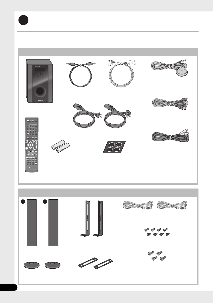
8
Fr
Guide de configuration (HTP-FS510)
Contenu de l’emballage
Assurez-vous que tous les articles suivants sont présents.
1
SYSTEM
SYSTEM TV CONTROL
CH
VOL
DIMMER
SIGNAL SEL
BD MENU
DISPLAY
SURROUND SYSTEM
CH
CH
ENTER
ENTER
MUTE
INPUT
SOURCE
Grands coussinets
antidérapants (pour caisson
de basses à récepteur) x4
Câble iPod x1
Piles (taille AAA, IEC R03)
x2
Microphone (pour
configuration Auto
MCACC) x1
Télécommande x1
Caisson de basses à
récepteur x1 Antenne à fil FM x1
Carte de garantie
Mode d’emploi (ce
document)
Cordons d’alimentation x2
Boîte du caisson de basses à récepteur (SX-SWR2)
Câble optique
numérique x1
Câble vidéo x1
A B
Boîte d’enceintes (S-SWR500FS)
Enceintes avant x2
Câbles d’enceinte x2
Montants x2
Bases pour support de
haut-parleur x2 Joints x2
Vis (courtes) x8
Vis (longues) x4
HTP-710_VYXCN_Fr.book 8 ページ 2010年8月23日 月曜日 午後6時37分

10
Fr
Guide de configuration (HTP-SB510)
Contenu de l’emballage
Assurez-vous que tous les articles suivants sont présents.
1
SYSTEM
SYSTEM TV CONTROL
CH
VOL
DIMMER
SIGNAL SEL
BD MENU
DISPLAY
SURROUND SYSTEM
CH
CH
ENTER
ENTER
MUTE
INPUT
SOURCE
Grands coussinets
antidérapants (pour caisson
de basses à récepteur) x4
Câble iPod x1
Piles (taille AAA, IEC R03)
x2
Microphone (pour
configuration Auto
MCACC) x1
Télécommande x1
Caisson de basses à
récepteur x1 Antenne à fil FM x1
Carte de garantie
Mode d’emploi (ce
document)
Cordons d’alimentation x2
Boîte du caisson de basses à récepteur (SX-SWR2)
Câble optique
numérique x1
Câble vidéo x1
Boîte d’enceinte (S-SB510)
Enceinte x1 Câble d’enceinte x1
Supports de haut-parleur x2
Vis x2
Petits coussinets antidérapants
(pour supports d’enceinte/pour enceinte) x10
HTP-710_VYXCN_Fr.book 10 ページ 2010年8月23日 月曜日 午後6時37分
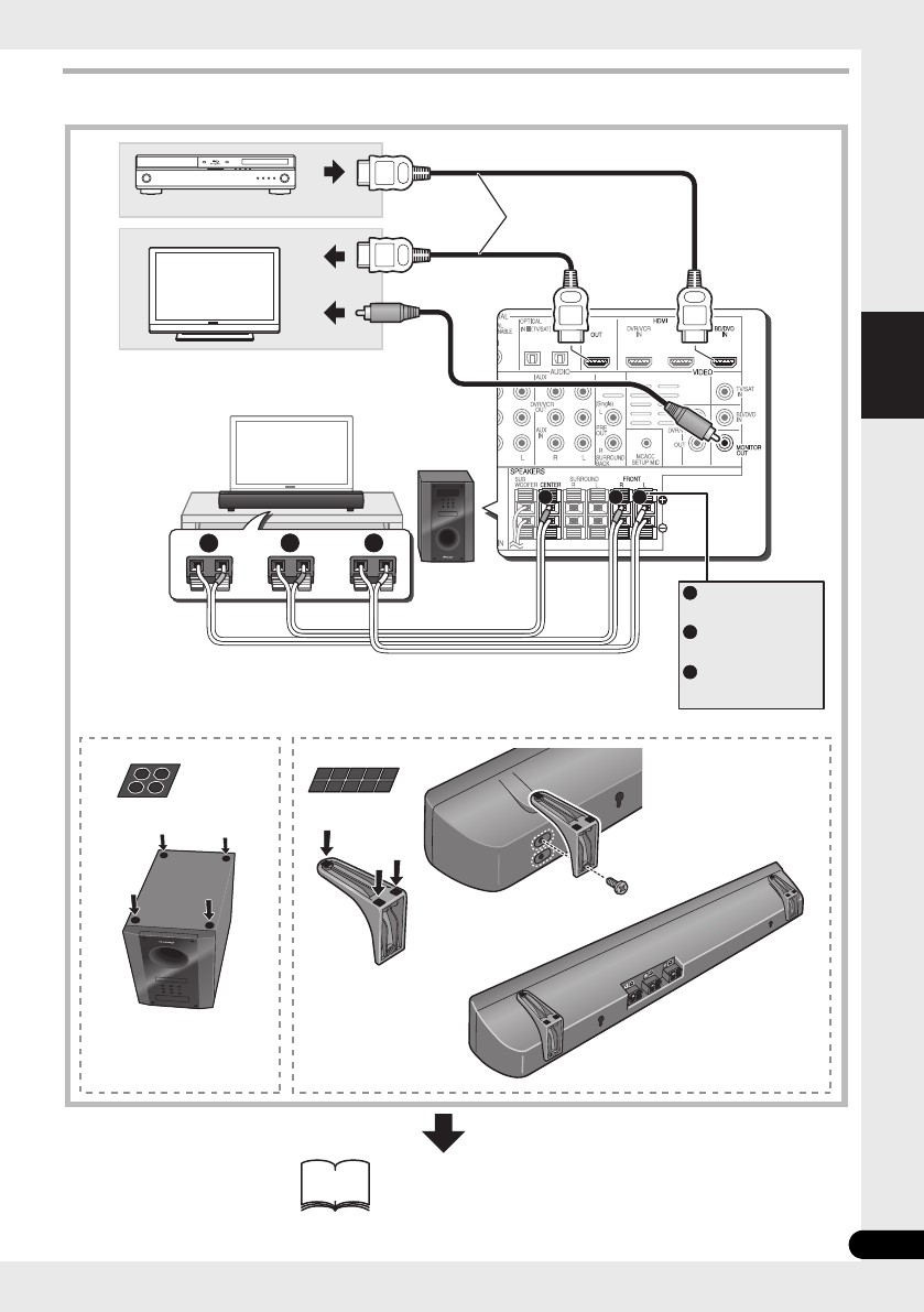
11
Fr
Français
Connexions
1 2
BA
FRONT
-
L
FRONT
-
R
CENTER
A
B
C
HDMI OUT
HDMI IN
VIDEO IN
12
C
A
C
B
Blanc
Rouge
Vert
Pour une écoute personnelle
(MCACC)
Disponible dans
le commerce
HTP-710_VYXCN_Fr.book 11 ページ 2010年8月23日 月曜日 午後6時37分
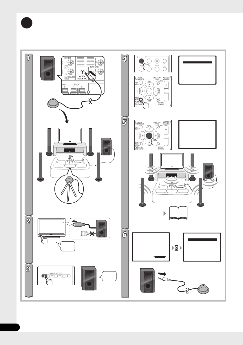
12
Fr
Pour une écoute personnelle
(MCACC)
2
(HTP-710)
(HTP-710)
SYSTEM SOURCE
SYSTEM TV CONTROL
CH
INPUT
ENTER
ENTER
System Setup
1.Auto MCACC
2.Manual SP Setup
Return
System Setup
1.Auto MCACC
2.Manual SP Setup
Return
1.Auto MCACC
Now Analyzing
Environment Check
Ambient Noise
Speaker YES/NO
Return
1.Auto MCACC
Check!
OK
Return
10:Next
Front
Center
Surr
Surr. Back
Subwoofer
[ YES ]
[ YES ]
[ YES ]
[YESx2]
[ YES ]
51
-
53
?
VIDEO IN
HDMI
Allumez
Allumez Allumez
HTP-710_VYXCN_Fr.book 12 ページ 2010年8月23日 月曜日 午後6時37分

14
Fr
Nous vous remercions d’avoir acheté ce produit Pioneer.
Veuillez lire attentivement ce mode d’emploi afin d’apprendre à utiliser votre modèle correctement.
Lorsque vous avez terminé, rangez ces instructions en lieu sûr afin de pouvoir vous y référer à l’avenir
.
Sommaire
Guide de configuration
HTP-710........................................4
HTP-610........................................6
HTP-FS510....................................8
HTP-SB510..................................10
Pour une écoute personnelle
(MCACC) .........................................12
Home Cinéma.................................13
01 Installation des enceintes
(HTP-710)
Précautions de sécurité lors de l’installation
. . .16
Installation du Home Cinéma . . . . . . . . . .16
Préparation des enceintes . . . . . . . . . . . . .16
Fixation des enceintes avant et d’ambiance
. . .18
Fixation de l’enceinte centrale sur une paroi
. . .18
Avant l’installation. . . . . . . . . . . . . . . . . .18
Remarques complémentaires sur la
disposition des enceintes . . . . . . . . . . . . .19
01 Installation des enceintes
(HTP-610)
Précautions de sécurité lors de l’installation
. . .20
Installation du Home Cinéma . . . . . . . . . .20
Préparation des enceintes . . . . . . . . . . . . .20
Fixation des enceintes sur une paroi . . . . .22
Avant l’installation. . . . . . . . . . . . . . . . . .22
Remarques complémentaires sur la
disposition des enceintes . . . . . . . . . . . . .23
01 Installation des enceintes
(HTP-FS510)
Précautions de sécurité lors de
l’installation. . . . . . . . . . . . . . . . . . . . . . . .24
Installation du Home Cinéma . . . . . . . . . .24
Préparation des enceintes . . . . . . . . . . . . .24
Fixation des enceintes sur une paroi . . . . .26
Avant l’installation. . . . . . . . . . . . . . . . . .26
Fixation des enceintes. . . . . . . . . . . . . . .27
Remarques complémentaires sur la
disposition des enceintes . . . . . . . . . . . . . 27
Pour une qualité sonore améliorée . . . . . . 27
01 Installation des enceintes
(HTP-SB510)
Précautions de sécurité lors de l’installation
. . . 28
Installation du Home Cinéma . . . . . . . . . . 28
Préparation des enceintes. . . . . . . . . . . . . 28
Fixation de l’enceinte sur une paroi. . . . . . 30
Avant l’installation . . . . . . . . . . . . . . . . . 30
Remarques complémentaires sur la
disposition des enceintes . . . . . . . . . . . . . 31
Pour une qualité sonore améliorée . . . . . . 31
02 Connexions
Panneau arrière . . . . . . . . . . . . . . . . . . . . 32
Lors du branchement des câbles . . . . . . . 33
À
propos du branchement aux prises vidéo
. . . 33
Câbles HDMI . . . . . . . . . . . . . . . . . . . . . 33
Câbles audio analogiques. . . . . . . . . . . . 34
Câbles audio numériques . . . . . . . . . . . . 34
Connexion à votre téléviseur (pour sons
télévisés). . . . . . . . . . . . . . . . . . . . . . . . . . 35
Branchement du téléviseur et des composants
de lecture . . . . . . . . . . . . . . . . . . . . . . . . . 36
Connexion au moyen de l’interface HDMI
. . . 36
Branchement d’un composant sans borne
HDMI . . . . . . . . . . . . . . . . . . . . . . . . . . . 37
Branchement d’un enregistreur HDD/DVD,
magnétoscope ou autres sources vidéo
. . . 38
Raccordement d’un récepteur satellite ou d’un
boîtier décodeur numérique . . . . . . . . . . . 39
Connexion d’autres appareils audio . . . . . 40
Branchement sur la borne vidéo du panneau
avant. . . . . . . . . . . . . . . . . . . . . . . . . . . . . 41
Branchement d’un iPod/iPhone . . . . . . . . 41
Branchement d’une clé USB. . . . . . . . . . . 42
Branchement de l’antenne FM . . . . . . . . . 42
Connexion d’antennes extérieures . . . . . 42
Emploi des sorties PRE OUT pour raccorder les
enceintes surround arrière . . . . . . . . . . . . 43
Branchement du système . . . . . . . . . . . . . 43
HTP-710_VYXCN_Fr.book 14 ページ 2010年8月23日 月曜日 午後6時37分

15
Fr
Français
03 Commandes et affichages
Panneau avant . . . . . . . . . . . . . . . . . . . . . 44
Affichage . . . . . . . . . . . . . . . . . . . . . . . . 45
Télécommande . . . . . . . . . . . . . . . . . . . . 47
Mise en place des piles dans la
télécommande. . . . . . . . . . . . . . . . . . . . 50
Utilisation de la télécommande . . . . . . . 50
04 Pour commencer
Configuration automatique du son surround
(MCACC) . . . . . . . . . . . . . . . . . . . . . . . . . 51
Autres problèmes lors de la Configuration
MCACC automatique. . . . . . . . . . . . . . . 53
Démarches de base . . . . . . . . . . . . . . . . . 53
Sélection du signal d’entrée . . . . . . . . . 54
05 Lecture iPod/USB
Lecture par iPod. . . . . . . . . . . . . . . . . . . . 55
Lecture de l’iPod . . . . . . . . . . . . . . . . . . 55
Visualisation de photos et de contenu
vidéo . . . . . . . . . . . . . . . . . . . . . . . . . . . 56
À propos de l’iPod/iPhone . . . . . . . . . . . 57
Utilisation d’une clé USB . . . . . . . . . . . . . 57
Commandes de base pour la lecture . . . 58
Compatibilité des fichiers audio
compressés . . . . . . . . . . . . . . . . . . . . . . 59
06 Utilisation du tuner
Écoute de la radio . . . . . . . . . . . . . . . . . . 60
Amélioration du son stéréo FM . . . . . . . 60
Mémorisation de stations préréglées . . . . 60
Écoute des stations préréglées . . . . . . . 61
Attribution de noms aux stations
préréglées . . . . . . . . . . . . . . . . . . . . . . . 61
Introduction au système RDS. . . . . . . . . . 61
Recherche de programmes RDS . . . . . . 62
Affichage des informations RDS . . . . . . 62
07 Écoute de votre système
Sélection du mode d’écoute. . . . . . . . . . . 63
Lecture en mode Auto . . . . . . . . . . . . . . . 63
Écoute de sonorités d’ambiance . . . . . . . 63
Utilisation des effets surround avancés
. . . 64
Écoute en stéréo . . . . . . . . . . . . . . . . . . . 64
Utilisation de “Front Stage Surround
Advance” . . . . . . . . . . . . . . . . . . . . . . . . . 65
Utilisation des modes Stream Direct . . . . 65
Utilisation de la fonction Sound Retriever
. . . . 66
Écoute avec Égalisateur d’étalonnage
acoustique . . . . . . . . . . . . . . . . . . . . . . . . 66
Amélioration du son par Phase Control
. . . 66
Fonctions avec enceintes surround arrière
raccordées . . . . . . . . . . . . . . . . . . . . . . . .67
Mode de sonorités d’ambiance . . . . . . . .67
Utilisation du traitement de canal surround
arrière . . . . . . . . . . . . . . . . . . . . . . . . . . .68
Réglage de la fonction Up Mix . . . . . . . .68
Réglage des options audio . . . . . . . . . . . .69
08 Menu de configuration du
système
Utilisation du menu de configuration du
système. . . . . . . . . . . . . . . . . . . . . . . . . . .72
Configuration manuelle des enceintes . . .72
Réglage des enceintes . . . . . . . . . . . . . .73
Niveau des canaux . . . . . . . . . . . . . . . . .73
Distance des enceintes. . . . . . . . . . . . . .74
09 Commande des autres fonctions
du système
Préparation de la télécommande pour gérer
d’autres composants. . . . . . . . . . . . . . . . .75
Sélection directe des codes de préréglage
. . .75
Suppression de tous les réglages de la
télécommande . . . . . . . . . . . . . . . . . . . . .75
Commandes pour téléviseurs . . . . . . . . . .76
Commandes pour autres composants. . . .77
Liste des codes de préréglage . . . . . . . . . .79
10 Informations complémentaires
Guide de dépannage . . . . . . . . . . . . . . . . .84
HDMI . . . . . . . . . . . . . . . . . . . . . . . . . . .86
Information importante relative à la
connexion HDMI . . . . . . . . . . . . . . . . . . .87
iPodMessages. . . . . . . . . . . . . . . . . . . . .88
Messages USB . . . . . . . . . . . . . . . . . . . .88
Réinitialisation de l’appareil principal . . . .88
Caractéristiques techniques . . . . . . . . . . .89
Caisson de basses à récepteur SX-SWR2
. . .89
Enceinte S-DV595T (HTP-710) . . . . . . . . .89
Enceinte S-SWR600 (HTP-610) . . . . . . . .89
Enceinte S-SWR500FS (HTP-FS510) . . . .90
Enceinte S-SB510 (HTP-SB510). . . . . . . .90
Nettoyage de l’appareil . . . . . . . . . . . . . . .90
HTP-710_VYXCN_Fr.book 15 ページ 2010年8月23日 月曜日 午後6時37分

Installation des enceintes (HTP-710)01
16
Fr
Chapitre 1-1
Installation des enceintes
(HTP-710)
Précautions de sécurité lors de
l’installation
Lors de l’installation des enceintes, posez-les à
plat sur leur flanc pour éviter des accidents ou
des blessures. Veillez à utiliser une surface
stable lors de l’assemblage, de l’installation et
de la disposition des enceintes.
Installation du Home Cinéma
Voici une configuration standard des
enceintes à son d’ambiance (Surround) multi-
voies pour bénéficier d’un son optimal du
Home Theater à 5.1 voies. Les enceintes avant
gauche et droite doivent être éloignées de 1,8
m à 2,7 m environ.
Préparation des enceintes
1 Fixez les coussinets antidérapants sur la
base de chaque support d’enceinte et du
caisson de basses du récepteur.
Pour les bases de support d’enceinte :
Utilisez l’adhésif fourni pour fixer quatre petits
coussinets sur la base (fond) de chaque
support d’enceinte.
Pour caisson de basses :
Utilisez l’adhésif fourni pour fixer quatre
grands coussinets sur la base du caisson de
basses.
Enceinte avant gauche Enceinte avant droite
Enceinte surround
gauche Enceinte
surround droite
Position d’écoute
Centre
Caisson de
basses
Petits coussinets
antidérapants
Grands coussinets
antidérapants
HTP-710_VYXCN_Fr.book 16 ページ 2010年8月23日 月曜日 午後6時37分

Installation des enceintes (HTP-710) 01
17
Fr
Français
2 Fixez les bases de support d’enceinte sur
les tiges au moyen des vis fournies.
Une fois que vous avez aligné la tige et la base,
fixez-les au moyen des petites vis aux endroits
indiqués ci-dessous. Notez que l’enceinte doit
être dirigée dans le sens de la base du triangle
isocèle.
ATTENTION
• Veillez à ne pas serrer excessivement les vis.
• Si vous utilisez une force excessive pour
serrer les vis, les filetages de la vis et/ou de
l’écrou risquent d’être endommagés.
Utilisez un tournevis manuel de taille
moyenne pour l’assemblage.
• N’utilisez pas de tournevis électrique ou de
trop grande taille pouvant exercer une
force excessive sur les vis et les écrous.
• Vérifiez qu’aucun corps étranger n’est
collé à la base de support ou à l’enceinte
haute pendant l’assemblage.
• Si l’appareil est assemblé alors qu’un
corps étranger collé entre la base de
support et l’enceinte haute, l’appareil
risque de ne pas être assemblé de façon
sûre et de basculer ou tomber.
• Ne montez pas sur la base de support de
l’enceinte haute pour pousser ou faire
basculer l’enceinte. L’enceinte pourrait
tomber et se casser, ou quelqu’un pourrait
en être blessé. Faites particulièrement
attention aux enfants.
3 Branchez chaque enceinte.
Branchez les fils sur l’enceinte. Chaque
enceinte sur l’illustration peut être identifée
grâce au repère coloré, prévu sur l’étiquette de
la surface arrière.
Enceinte avant gauche : Blanc
Enceinte avant droite : Rouge
Enceinte centrale : Vert
Enceinte d’ambiance gauche : Bleu
Enceinte d’ambiance droite : Gris
Associez le fil à code couleur à l’indicateur de
couleur sur l’étiquette, puis insérez le fil à code
couleur du côté rouge (+) et l’autre fil du côté
noir (–).
Raccordez l’autre bout sur les bornes
d’enceinte à code couleur à l’arrière du
caisson de basses à récepteur.
Arrière
Avant
Noir
(–)
Rouge (+) Fil à code couleur
Noir
(–)
Fil à code couleur
Taquet à code couleur (+)
HTP-710_VYXCN_Fr.book 17 ページ 2010年8月23日 月曜日 午後6時37分

Installation des enceintes (HTP-710) 01
19
Fr
Français
voulez fixer les enceintes soit assez
resistante pour les supporter. Ne l’installez
pas sur une surface en contreplaqué ou sur
une paroi friable.
• Des vis de montage ne sont pas fournies.
Utilisez des vis appropriées au matériau de
la paroi et pouvant résister au poids des
enceintes.
ATTENTION
• Si vous hésitez quant aux propriétés et à la
résistance des parois, demandez conseil à
un professionnel.
• Pioneer n’assume aucune responsabilité
en cas d’accident ou de dégâts, découlant
d’une installation inadéquate.
Remarques complémentaires
sur la disposition des enceintes
• Installez les enceintes principales avant
gauche et droit à égale distance du
téléviseur.
• Pour obtenir un effet optimal, installez les
enceintes d’ambiance légèrement au-
dessus du niveau des oreilles.
• Téléviseurs prenant en compte les signaux
d’affichage 3D transmis aux lunettes 3D
portées par le spectateur. Pour voir les
images en 3 dimensions, consultez le
Mode d’emploi du téléviseur et installez
l’enceinte centrale de sorte qu’elle ne gêne
pas l’émetteur de signal 3D du téléviseur.
Précautions :
• Si vous installez l’enceinte centrale sur le
téléviseur, veillez à l’immobiliser de façon
appropriée. Sinon l’enceinte risque de
tomber du téléviseur à la suite de chocs
externes ou d’un séisme, ce qui pourrrait
blesser les personnes à proximité et
endommager l’enceinte proprement dite.
• Assurez-vous que tout le fil dénudé des
enceintes est entortillé et entièrement
inséré dans la borne de l’enceinte. Si l’un
des fils nus d’une enceinte touche le
panneau arrière, l’alimentation peut se
couper par mesure de sécurité.
• Les enceintes avant, centrale et
d’ambiance fournies avec ce système sont
blindées magnétiquement. Toutefois,
selon l’endroit d’installation, une
distorsion des couleurs peut se produire si
les haut-parleurs sont placés tout près de
l’écran d’un téléviseur. Si ce cas se produit,
mettez le téléviseur hors tension, puis
remettez-le sous tension environ 15
minutes à 30 minutes plus tard. Si le
problème subsiste, éloignez les enceintes
par rapport au téléviseur.
• Le caisson de basses n’étant pas blindé
magnétiquement, ne le placez pas à
proximité d’un téléviseur ou d’un moniteur.
Ne placez pas des supports de
mémorisation magnétique (tels que
disquettes, des bandes ou des cassettes
vidéo) à proximité du caisson de basses.
• Ne fixez pas les enceintes avant et
d’ambiance, ni le caisson de basses sur
une paroi ou au plafond. Ils pourraient
causer des blessures en tombant.
• Ne montez pas sur la base de support de
l’enceinte haute pour pousser ou faire
basculer l’enceinte. L’enceinte pourrait
tomber et se casser, ou quelqu’un pourrait
en être blessé. Faites particulièrement
attention aux enfants.
5 mm
10 mm
Vis de fixation
(non fournies)
5 mm à 7 mm
HTP-710_VYXCN_Fr.book 19 ページ 2010年8月23日 月曜日 午後6時37分

Installation des enceintes (HTP-610) 01
21
Fr
Français
2 (Lors d’un montage des enceintes
centrales à droite et à gauche) Superposez-les
et fixez-les avec l’applique.
Chaque enceinte dispose d’un indicateur de
couleur sur l’étiquette de modèle à l’arrière
afin d’aider à l’identifier. Reportez-vous aux
indicateurs de couleur et installez
correctement les enceintes.
Comme indiqué sur l’illustration, superposez
les enceintes. Alignez l’applique
respectivement avec les trous de vis supérieurs
et inférieurs comme indiqué sur chaque figure
ci-dessous et fixez les vis de façon sûre.
ATTENTION
• N’essayez pas de transporter les enceintes
lorsqu’elles sont reliées avec l’applique.
Cela pourrait endommager l’applique ou
aggraver les dommages de celle-ci et des
enceintes en cas de chute.
3 Branchez chaque enceinte.
Branchez les fils sur l’enceinte. Chaque
enceinte sur l’illustration peut être identifée
grâce au repère coloré, prévu sur l’étiquette de
la surface arrière.
Enceinte avant gauche : Blanc
Enceinte avant droite : Rouge
Enceinte centrale : Vert
Enceinte d’ambiance gauche : Bleu
Enceinte d’ambiance droite : Gris
Associez le fil à code couleur à l’indicateur de
couleur sur l’étiquette, puis insérez le fil à code
couleur du côté rouge (+) et l’autre fil du côté
noir (–).
• Lorsque vous raccordez les enceintes
centrales, raccordez de la même façon
l’extrémité double du câble en Y aux deux
enceintes centrales.
Étiquette de modèle
Indicateur de
couleur
Gauche Droite
Vert
Enceinte
centrale
Enceinte
avant
Vert
Blanc Rouge
Applique
Vis
Enceinte
centrale
Enceinte
avant
Noir
(–)
Rouge (+) Fil à code couleur
Câble en Y
Au caisson des basses à
récepteur
HTP-710_VYXCN_Fr.book 21 ページ 2010年8月23日 月曜日 午後6時37分

Installation des enceintes (HTP-610)01
22
Fr
Raccordez l’autre bout sur les bornes
d’enceinte à code couleur à l’arrière du
caisson de basses à récepteur.
ATTENTION
• Ces bornes d’enceinte ont une TENSION
POTENTIELLEMENT MORTELLE. Pour
éviter toute décharge électrique lors du
branchement ou du débranchement des
câbles d’enceinte, débranchez le cordon
d’alimentation avant de toucher des pièces
non isolées.
• Ne raccordez à ce système aucun haut-
parleur autre que ceux qui sont fournis.
• Ne raccordez pas les haut-parleurs fournis
à un amplificateur autre que celui fourni
avec ce système. Une telle connexion
pourrait provoquer une défaillance, voire
un incendie.
• Après avoir raccordé les fiches, tirez
légèrement sur les câbles pour vous
assurer que leurs extrémités sont
raccordées de façon sûre aux bornes. Des
mauvais raccordements peuvent créer du
bruit et provoquer des interruptions du
son.
• Si les fils du câble ressortent des bornes et
entrent en contact les uns avec les autres,
cela peut placer une charge
supplémentaire excessive sur
l’amplificateur et peut provoquer un arrêt
de son fonctionnement, voire même
l’endommager.
Fixation des enceintes sur une
paroi
Toutes les enceintes (à l’exception du caisson
de basses qui doit être posé sur le sol)
présentent des orifices pour appliques de
montage ; en fonction de la configuration
choisie, vous pouvez donc monter les
enceintes avant, centrales et d’ambiance sur
une paroi.
• Assurez-vous de serrer la vis fournie aussi
fermement que possible lorsque vous
installez l’applique à l’arrière de l’enceinte.
Avant l’installation
• Sachez que les enceintes sont pesantes et
que leur poids peut entraîner le
détachement des vis à bois ou
l’arrachement du matériau auxquels elles
sont fixées, ce qui provoquerait leur chute.
Assurez-vous que la paroi sur laquelle vous
voulez fixer les enceintes soit assez
resistante pour les supporter. Ne l’installez
pas sur une surface en contreplaqué ou
sur une paroi friable.
• Des vis de montage ne sont pas fournies.
Utilisez des vis appropriées au matériau de
la paroi et pouvant résister au poids des
enceintes.
ATTENTION
• Si vous hésitez quant aux propriétés et à la
résistance des parois, demandez conseil à
un professionnel.
• Pioneer n’assume aucune responsabilité
en cas d’accident ou de dégâts, découlant
d’une installation inadéquate.
Noir
(–)
Fil à code couleur
Taquet à code couleur (+)
HTP-710_VYXCN_Fr.book 22 ページ 2010年8月23日 月曜日 午後6時37分

Installation des enceintes (HTP-610) 01
23
Fr
Français
Remarques complémentaires
sur la disposition des enceintes
• Installez les enceintes principales avant
gauche et droit à égale distance du
téléviseur.
• Pour obtenir un effet optimal, installez les
enceintes d’ambiance légèrement au-
dessus du niveau des oreilles.
• Téléviseurs prenant en compte les signaux
d’affichage 3D transmis aux lunettes 3D
portées par le spectateur. Pour voir les
images en 3 dimensions, consultez le
Mode d’emploi du téléviseur et installez
l’enceinte centrale de sorte qu’elle ne gêne
pas l’émetteur de signal 3D du téléviseur.
Précautions :
• Si vous installez l’enceinte centrale sur le
téléviseur, veillez à l’immobiliser de façon
appropriée. Sinon l’enceinte risque de
tomber du téléviseur à la suite de chocs
externes ou d’un séisme, ce qui pourrrait
blesser les personnes à proximité et
endommager l’enceinte proprement dite.
• Les enceintes avant, centrale et
d’ambiance fournies avec ce système sont
blindées magnétiquement. Toutefois,
selon l’endroit d’installation, une
distorsion des couleurs peut se produire si
les haut-parleurs sont placés tout près de
l’écran d’un téléviseur. Dans ce cas,
mettez le téléviseur hors tension, puis
remettez-le sous tension environ 15
minutes à 30 minutes plus tard. Si la
difficulté subsiste, éloignez les enceintes
par rapport au téléviseur.
• Le caisson de basses n’étant pas blindé
magnétiquement, ne le placez pas à
proximité d’un téléviseur ou d’un moniteur.
Ne placez pas des supports de
mémorisation magnétique (tels que
disquettes, des bandes ou des cassettes
vidéo) à proximité du caisson de basses.
• Ne fixez pas le caisson de basses sur une
paroi ou au plafond. Ils pourraient causer
des blessures en tombant.
Applique de montage
(fournie)
Vis (fournie)
5 mm à 7 mm
Vis de fixation
(non fournies) 5 mm
10 mm
HTP-710_VYXCN_Fr.book 23 ページ 2010年8月23日 月曜日 午後6時37分

Installation des enceintes (HTP-FS510)01
24
Fr
Chapitre 1-3
Installation des enceintes
(HTP-FS510)
Précautions de sécurité lors de
l’installation
Lors de l’installation des enceintes, posez-les à
plat sur leur flanc pour éviter des accidents ou
des blessures. Veillez à utiliser une surface
stable lors de l’assemblage, de l’installation et
de la disposition des enceintes.
Installation du Home Cinéma
Voici un agencement standard des enceintes.
Les enceintes avant gauche et droite doivent
être éloignées de 1,8 m à 2,7 m environ.
Préparation des enceintes
1 Fixez les coussinets antidérapants sur la
base du caisson de basses à récepteur.
Utilisez l’adhésif fourni pour fixer quatre
coussinets sur la base du caisson de basses.
2 Insérez le montant par les orifices
derrière la base et fixez-le au moyen des 4
vis.
ATTENTION
• Veillez à ne pas serrer excessivement les vis.
• Si vous utilisez une force excessive pour
serrer les vis, les filetages de la vis et/ou de
l’écrou risquent d’être endommagés.
Utilisez un tournevis manuel de taille
moyenne pour l’assemblage.
• N’utilisez pas de tournevis électrique ou de
trop grande taille pouvant exercer une
force excessive sur les vis et les écrous.
• Vérifiez qu’aucun corps étranger n’est
collé à la base de support ou à l’enceinte
haute pendant l’assemblage.
• Si l’appareil est assemblé alors qu’un
corps étranger collé entre la base de
support et l’enceinte haute, l’appareil
risque de ne pas être assemblé de façon
sûre et de basculer ou tomber.
Enceinte
avant
gauche
Enceinte avant droite
Caisson de basses
Coussinets
antidérapants
HTP-710_VYXCN_Fr.book 24 ページ 2010年8月23日 月曜日 午後6時37分
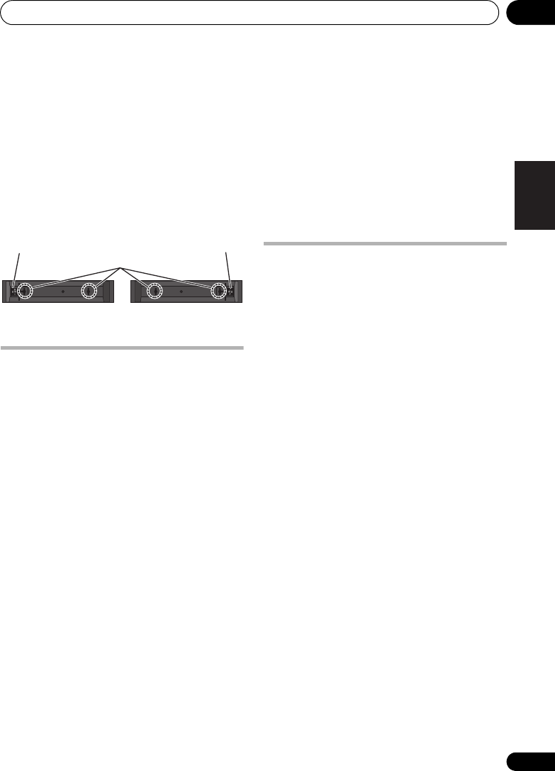
Installation des enceintes (HTP-FS510) 01
27
Fr
Français
Fixation des enceintes
L’enceinte avant peut être fixée à la verticale ou
à l’horizontale sur une paroi. Utilisez un trou
pour la suspendre verticalement et deux trous
pour la suspendre horizontalement.
Lors d’une installation horizontale, fixez
l’enceinte de sorte que sa borne sur la face
arrière se trouve sur le côté extérieur de la
surface, le plus loin possible de l’autre
enceinte.
Remarques complémentaires
sur la disposition des
enceintes
• Installez les enceintes avant gauche et
droit à égale distance du téléviseur.
Précautions :
• Assurez-vous que tout le fil dénudé des
enceintes est entortillé et entièrement
inséré dans la borne de l’enceinte. Si l’un
des fils nus d’une enceinte touche le
panneau arrière, l’alimentation peut se
couper par mesure de sécurité.
• Les enceintes avant fournies avec ce
système sont blindées magnétiquement.
Toutefois, selon l’endroit d’installation, une
distorsion des couleurs peut se produire si
les haut-parleurs sont placés tout près de
l’écran d’un téléviseur. Si ce cas se produit,
mettez le téléviseur hors tension, puis
remettez-le sous tension environ 15
minutes à 30 minutes plus tard. Si le
problème subsiste, éloignez les enceintes
par rapport au téléviseur.
• Le caisson de basses n’étant pas blindé
magnétiquement, ne le placez pas à
proximité d’un téléviseur ou d’un moniteur.
Ne placez pas des supports de
mémorisation magnétique (tels que
disquettes, des bandes ou des cassettes
vidéo) à proximité du caisson de basses.
• Ne fixez pas le caisson de basses sur une
paroi ou au plafond. Ils pourraient causer
des blessures en tombant.
Pour une qualité sonore
améliorée
Il est possible de se constituer facilement un
ensemble Home Cinéma au moyen des
enceintes avant (gauche/droit) et du caisson
de basses de ce jeu ; toutefois, vous
bénéficierez d’un véritable son d’ambiance à
5.1 voies en faisant appel aux enceintes S-
SWR5CR en option.
Tenez compte des points suivants lors du
branchement des enceintes en option :
• Lorsque le contenu de ce Mode d’emploi à
partir du Chapitre 2 décrit un modèle
particulier, utilisez les sections qui traitent
du HTP-610.
• Pour des renseignements relatifs à
l’installation et au branchement des
enceintes en option, consultez les
informations, fournies avec ces enceintes
en option, et celles de la section
Installation des enceintes (HTP-610)
page 20 de ce Mode d’emploi.
• Reportez-vous à Configuration automatique
du son surround (MCACC) page 51 pour
configurer à nouveau votre système au
moyen de MCACC.
Trous de fixation
Borne d’enceinte
Borne d’enceinte
Enceinte avant
droite
Enceinte avant
gauche
HTP-710_VYXCN_Fr.book 27 ページ 2010年8月23日 月曜日 午後6時37分

Installation des enceintes (HTP-SB510)01
28
Fr
Chapitre 1-4
Installation des enceintes
(HTP-SB510)
Précautions de sécurité lors de
l’installation
Lors de l’installation des enceintes, posez-les à
plat sur leur flanc pour éviter des accidents ou
des blessures. Veillez à utiliser une surface
stable lors de l’assemblage, de l’installation et
de la disposition des enceintes.
Installation du Home Cinéma
L’enceinte doit être installée sous (ou devant)
le téléviseur. La hauteur des supports
d’enceinte peut être ajustée, ou bien l’enceinte
peut être installée sans utiliser les supports.
• Comme l’enceinte et le caisson de basses
ne sont pas blindés magnétiquement, on
ne les placera pas près d’un téléviseur à
tube cathodique.
Préparation des enceintes
1 Fixez les coussinets antidérapants sur la
base des supports d’enceinte et du caisson de
basses à récepteur.
Pour les supports d’enceinte :
Utilisez l’adhésif fourni pour fixer trois petits
coussinets sur la base (fond) de chaque
support d’enceinte.
Pour caisson de basses :
Utilisez l’adhésif fourni pour fixer quatre
grands coussinets sur la base du caisson de
basses.
Enceinte
Caisson de
basses
Petits coussinets
antidérapants
Grands coussinets
antidérapants
HTP-710_VYXCN_Fr.book 28 ページ 2010年8月23日 月曜日 午後6時37分

Installation des enceintes (HTP-SB510) 01
29
Fr
Français
Si vous décidez de ne pas employer les
supports d’enceinte, utilisez l’adhésif fourni
pour fixer quatre petits coussinets sur la base
de l’enceinte.
2 Fixez les bases de support d’enceinte sur
l’enceinte.
Fixez les supports d’enceinte gauche et droit à
l’arrière de l’enceinte. La hauteur des supports
d’enceinte peut être ajustée selon deux
niveaux ; choisissez celui qui vous convient et
fixez les supports.
ATTENTION
• Veillez à ne pas serrer excessivement les vis.
• Si vous utilisez une force excessive pour
serrer les vis, leurs filetages risquent d’être
endommagés. Utilisez un tournevis
manuel de taille moyenne pour
l’assemblage.
• N’utilisez pas de tournevis électrique ou de
trop grande taille pouvant exercer une
force excessive sur les vis et les écrous.
• Vérifiez qu’aucun corps étranger n’est
collé au support ou à l’enceinte pendant
l’assemblage.
• Si l’appareil est assemblé alors qu’un
corps étranger est collé entre le support et
l’enceinte, l’appareil risque de ne pas être
assemblé de façon sûre et de basculer ou
de tomber.
3 Branchez chaque enceinte.
Branchez les fils sur l’enceinte.
Les bornes des canaux (Droit / Central /
Gauche) sont regroupées sur l’arrière de
l’enceinte et elles sont identifiées par des
étiquettes à code couleur.
Enceinte avant gauche : Blanc
Enceinte avant droite : Rouge
Enceinte centrale : Vert
Associez le fil à code couleur à l’indicateur de
couleur sur l’étiquette, puis insérez le fil à code
couleur du côté rouge (+) et l’autre fil du côté
noir (–).
Raccordez l’autre bout sur les bornes
d’enceinte à code couleur à l’arrière du
caisson de basses à récepteur.
Petits coussinets antidérapants
Noir
(–)
Rouge (+) Fil à code couleur
Noir
(–)
Fil à code couleur
Taquet à code couleur (+)
HTP-710_VYXCN_Fr.book 29 ページ 2010年8月23日 月曜日 午後6時37分

Installation des enceintes (HTP-SB510) 01
31
Fr
Français
Remarques complémentaires
sur la disposition des
enceintes
• Installez l’enceinte en-dessous du
téléviseur à une position centrale.
• Téléviseurs prenant en compte les signaux
d’affichage 3D transmis aux lunettes 3D
portées par le spectateur. Pour voir les
images en 3 dimensions, consultez le
Mode d’emploi du téléviseur et installez
l’enceinte de sorte qu’elle ne gêne pas
l’émetteur de signal 3D du téléviseur.
Précautions :
• Ne posez pas l’enceinte sur le téléviseur
proprement dit.
• Assurez-vous que tout le fil dénudé des
enceintes est entortillé et entièrement
inséré dans la borne de l’enceinte. Si l’un
des fils nus d’une enceinte touche le
panneau arrière, l’alimentation peut se
couper par mesure de sécurité.
• Comme l’enceinte et le caisson de basses
ne sont pas blindés magnétiquement, on
ne les placera pas près d’un téléviseur ou
d’un moniteur. Ne placez pas des supports
de mémorisation magnétique (tels que
disquettes, bandes ou cassettes vidéo) à
proximité de l’enceinte ou du caisson de
basses.
• Ne fixez pas le caisson de basses sur une
paroi ou au plafond. Ils pourraient causer
des blessures en tombant.
Pour une qualité sonore
améliorée
Il est possible de se constituer facilement un
ensemble Home Cinéma au moyen de
l’enceinte et du caisson de basses de ce jeu ;
toutefois, vous bénéficierez d’un véritable son
d’ambiance à 5.1 voies en faisant appel aux
enceintes S-SB5R en option.
Tenez compte des points suivants lors du
branchement des enceintes en option :
• Lorsque le contenu de ce Mode d’emploi à
partir du Chapitre 2 décrit un modèle
particulier, utilisez les sections qui traitent
du HTP-610.
• Pour des renseignements relatifs à
l’installation et au branchement des
enceintes en option, consultez les
informations, fournies avec ces enceintes
en option, et celles de la section
Installation des enceintes (HTP-610)
page 20 de ce Mode d’emploi.
• Reportez-vous à Configuration automatique
du son surround (MCACC) page 51 pour
configurer à nouveau votre système au
moyen de MCACC.
HTP-710_VYXCN_Fr.book 31 ページ 2010年8月23日 月曜日 午後6時37分

Connexions02
32
Fr
Chapitre 2
Connexions
Panneau arrière
1 Entrées audio numériques coaxiale/
optique (x3)
Utilisez le câble optique numérique fourni pour
raccorder l’entrée DIGITAL OPTICAL IN 1 (TV/
SAT) à la borne de sortie optique numérique du
téléviseur.
A utilisez pour les sources audio numériques,
y compris les lecteurs/enregistreurs DVD,
récepteurs satellite numériques, lecteurs CD,
etc.
2 Entrées (x3)/sortie (x1) HDMI
Entrées multiples et une sortie pour une
connexion audio/vidéo de haute qualité à des
appareils compatibles HDMI.
3 Prise d’antenne
FM
4 Entrées/sorties audio analogiques stéréo
A utiliser pour le branchement à des sources
audio, telles que lecteurs CD, magnétophones,
platines-disques, etc.
5 Sorties préampli arrière d’ambiance
A utiliser pour le branchement
d’amplificateurs séparés pour canaux
d’ambiance arrière.
6Prise
MCACC SETUP MIC
A utiliser pour le branchement du microphone
fourni en vue de la configuration MCACC
automatique (page 51).
7 Entrées/sorties vidéo
Utilisez le câble vidéo fourni pour raccorder la
borne MONITOR OUT à la borne d’entrée vidéo
du téléviseur.
A utiliser pour le branchement à des sources
vidéo, telles que lecteurs/enregistreurs DVD,
magnétoscopes, etc.
8
AC IN
– Prise d’alimentation
9 Bornes
SPEAKERS
(enceintes)
Faites correspondre les couleurs des câbles
d’enceintes et celles de leurs bornes
respectives.
1
1 2
7
8
9
6
5
4
3
21
HTP-710_VYXCN_Fr.book 32 ページ 2010年8月23日 月曜日 午後6時37分

Connexions 02
33
Fr
Français
Lors du branchement des câbles
Veillez à ne pas cheminer les câbles sur le
dessus de cet appareil. Si c’est le cas, le
champ magnétique produit par les
transformateurs de l’appareil risque de
provoquer un ronflement via les enceintes.
ATTENTION
• Lors du branchement de cet appareil ou
avant de changer ses connexions, coupez
l’interrupteur d’alimentation et débranchez
le cordon d’alimentation au niveau de la
prise secteur.
Toutes les connexions étant terminées,
branchez le cordon d’alimentation sur la
prise secteur.
À propos du branchement aux prises
vidéo
Ce système n’est pas doté d’un convertisseur
vidéo. Si vous utiliser un câble HDMI pour
brancher un dispositif d’entrée, les mêmes
câbles doivent être utilisés pour le téléviseur.
Câbles HDMI
Les câbles HDMI transmettent les signaux
vidéo numériques non compressés, ainsi que
la plupart des types de signaux audio
numériques avec lesquels le composant est
compatible, notamment DVD-vidéo, DVD-
Audio, Dolby Digital Plus, Dolby TrueHD, DTS-
HD Master Audio (Reportez-vous à les
limitations ci-dessous), Vidéo CD/Super VCD,
CD, SACD (DSD 2 voies seulement) et PCM
192 kHz/8 voies (nombre maximum
d’entrées).1
Veillez à connecter les bornes dans le sens
correct.
À propos de HDMI
La norme HDMI (High Definition Multimedia
Interface) prend en charge via une seule
connexion numérique à la fois les signaux
audio et vidéo, pour une utilisation avec des
appareils externes tels que lecteurs DVD,
téléviseurs numériques, ou autres appareils
audiovisuels. Cette norme a été créée pour
fournir des spécifications communes aux
normes HDCP (High Bandwidth Digital
Content Protection) et DVI (Digital Visual
Interface). La norme HDCP est utilisée pour
garantir la protection des données numériques
envoyées et reçues par les moniteurs
compatibles DVI.
La norme HDMI, quant à elle, prend en charge
la vidéo standard, améliorée ou à haute
définition, ainsi que l’audio standard et le son
d’ambiance multicanaux (surround). Les
spécifications de la norme HDMI incluent
notamment la vidéo numérique non
compressée, une largeur de bande allant
jusqu’à 2,2 giga-octets par seconde (pour un
signal HDTV), un connecteur unique (à la place
de plusieurs câbles et connecteurs), et la
capacité de communication entre une source
audiovisuelle et des appareils audiovisuels
externes tels que des téléviseurs numériques.
Remarque
1 • Réglez le paramètre HDMI sous Réglage des options audio page 69 à THRU (THROUGH) et réglez le signal d’entrée
sous Sélection du signal d’entrée page 54 à HDMI, si vous souhaitez écouter la sortie audio HDMI par votre téléviseur
(aucun son ne proviendra alors de ce système).
• Si le signal vidéo n’apparaît pas sur votre téléviseur, essayez d’ajuster la résolution sur votre composant ou sur
l’affichage. Sachez que certains composants (tels que consoles de jeu vidéo) ont une résolution qu’il n’est pas
possible d’afficher. Dans ce cas, utilisez une connexion composite (analogique).
• Les signaux captés aux entrées vidéo composite (analogiques) de cet appareil ne seront pas fournies par les sorties
HDMI OUT.
• Quand le signal vidéo de HDMI est 480i, 480p, 576i ou 576p, les sons PCM multi-voies et les sons HD ne peuvent
pas être reçus.
HTP-710_VYXCN_Fr.book 33 ページ 2010年8月23日 月曜日 午後6時37分

Connexions02
34
Fr
Ce système est compatible également avec la
fonction DeepColor et x.v.Color (x.v.Color est
une marque commerciale de Sony
Corporation).
HDMI, le logo HDMI et High-Definition
Multimedia Interface sont des marques
commerciales ou des marques déposées de
HDMI Licensing, LLC aux États-Unis et dans
d’autres pays.
Important
• En comparaison des formats existants
(optique et coaxial) de transmission des
sons numériques, un temps plus long est
nécessaire pour reconnaître les
transmissions de sons numériques en
format HDMI. C’est pourquoi, des
interruptions du son peuvent se produire
lors du changement de format ou au début
de la lecture.
En outre, la mise sous/hors tension du
composant raccordé à la borne HDMI OUT
de cet appareil ou le branchement/
débranchement du câble HDMI peut être
la cause de parasites ou d’une interruption
des sons.
Câbles audio analogiques
Utilisez des câbles phono RCA pour raccorder
les composants audio analogiques. Ces câbles
sont normalement rouges et blancs et vous
devez brancher les fiches rouges sur les
bornes R (droite) et les blanches sur les bornes
L (gauche).
Câbles audio numériques
Des câbles audio numériques coaxiaux ou des
câbles optiques, disponibles dans le
commerce, doivent être utilisés pour le
branchement de composants numériques sur
ce système.1
Câble audio numérique coaxial
Câble optique
• Un capuchon de protection a été installé
en usine sur le connecteur du câble
optique numérique fourni comme
accessoire. Veillez à enlever ce capuchon
avant de brancher le câble.
Câbles vidéo RCA ordinaires
Ces câbles sont la connexion vidéo la plus
commune et ils servent au branchement sur
les bornes vidéo composites. Les fiches jaunes
les distinguent des câbles pour les sons.
Remarque
1 • Lors de l’insertion de la fiche des câbles optiques, veillez à ne pas abîmer le volet protégeant la prise optique.
• Lors du rangement d’un câble optique, enroulez-le de façon lâche. Le câble pourrait être endommagé s’il est plié à
un angle réduit.
• Vous pouvez aussi faire appel à un câble vidéo RCA pour la connexion numérique coaxiale.
HTP-710_VYXCN_Fr.book 34 ページ 2010年8月23日 月曜日 午後6時37分
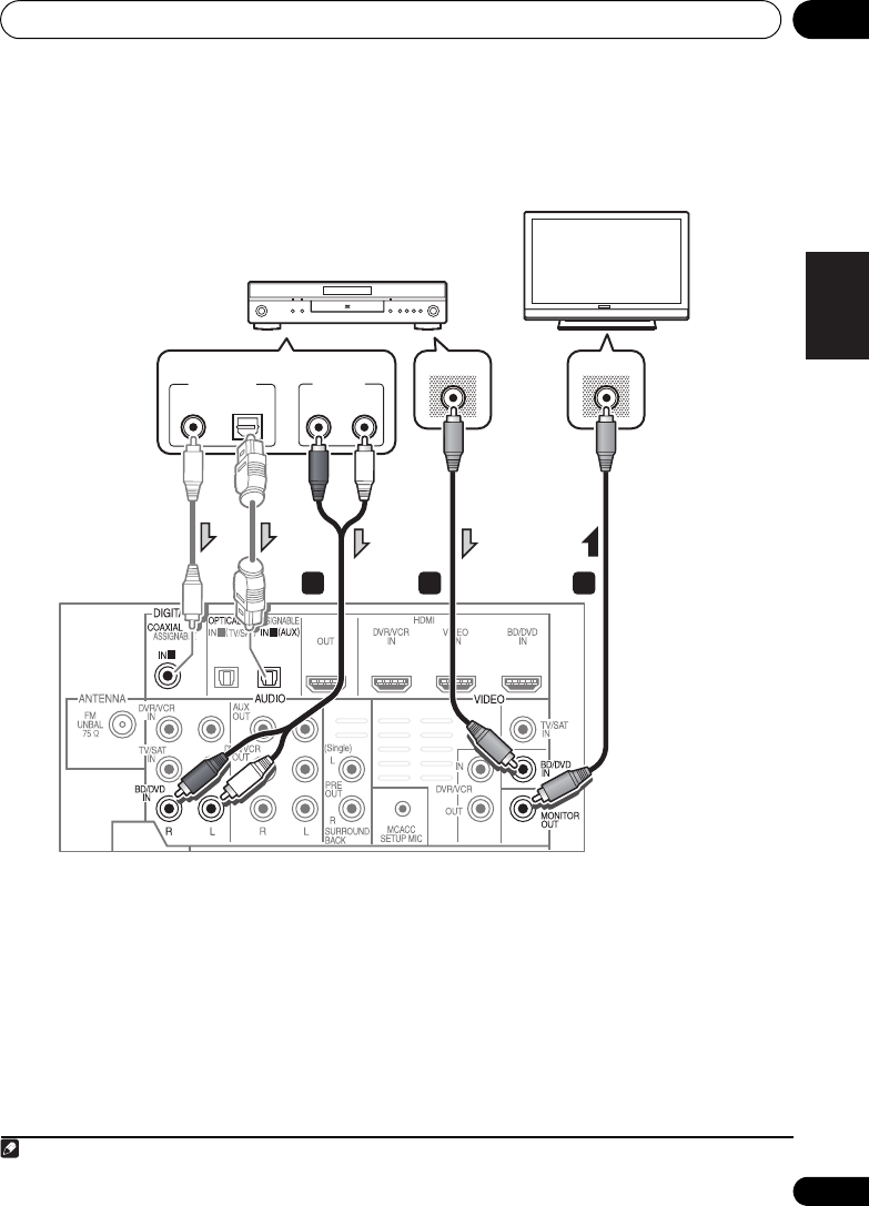
Connexions 02
37
Fr
Français
Branchement d’un composant sans borne HDMI
Ce schéma illustre les connexions à ce système d’un téléviseur et d’un lecteur DVD (ou d’un autre
composant de lecture) ne disposant pas d’une borne HDMI.
1 Branchez la sortie vidéo composite de
votre lecteur DVD sur l’entrée VIDEO BD/DVD
de ce système.
Utilisez un câble vidéo RCA ordinaire.
2 Branchez la sortie audio de votre lecteur
DVD sur les entrées AUDIO BD/DVD IN de ce
système.
Utilisez un câble phono RCA stéréo. Si votre
composant possède une sortie numérique, vous
pouvez également utilisez un câble optique ou un
câble coaxial pour le branchement.
1
3 Branchez la sortie MONITOR OUT de ce
système sur l’entrée vidéo composite de votre
téléviseur.
Utilisez le câble vidéo fourni.
1
1 2
1
2 3
VIDEO INVIDEO OUT
ANALOG
RL
AUDIO OUT
DIGITAL OUT
OPTICALCOAXIAL
Téléviseur
Lecteur DVD, etc.
Choisir une connexion
Remarque
1 Dans ce cas, vous devrez signifier à votre système à quelle entrée numérique votre téléviseur à été raccordé (Reportez-
vous à Sélection du signal d’entrée page 54).
HTP-710_VYXCN_Fr.book 37 ページ 2010年8月23日 月曜日 午後6時37分

Connexions02
38
Fr
Branchement d’un enregistreur HDD/DVD, magnétoscope ou autres
sources vidéo
Ce système est doté d’entrées et de sorties audio/vidéo, permettant le branchement
d’enregistreurs vidéo analogiques ou numériques, notamment des magnétoscopes et des
enregistreurs HDD/DVD.
1 Branchez la sortie vidéo composite de
votre composant vidéo sur l’entrée VIDEO
DVR/VCR de ce système.
Utilisez un câble vidéo RCA ordinaire.
• Si le composant vidéo raccordé est doté
d’une sortie HDMI, un câble HDMI peut
également servir pour cette connexion.
Dans ce cas, utilisez un câble HDMI pour
raccorder le téléviseur également.
2 Branchez la sortie VIDEO DVR/VCR OUT
de ce système sur l’entrée vidéo composite de
votre composant vidéo.
3 Branchez la sortie audio de votre
lcomposant vidéo sur les entrées AUDIO
DVR/VCR IN de ce système.
Utilisez un câble phono RCA stéréo. Si votre
composant possède une sortie numérique,
vous pouvez également utilisez un câble
optique ou un câble coaxial pour le
branchement.1
4 Raccordez l’entrée vidéo de l’enregistreur
sur la sortie VIDEO DVR/VCR de ce système.
Utilisez un câble vidéo RCA ordinaire.
1
1 2
HDMI OUT
ANALOG
RL
AUDIO IN
ANALOG
RL
AUDIO OUT
DIGITAL OUT
COAXIALOPTICAL VIDEO OUT
VIDEO IN
1
243
Choisir une connexion
Choisir une connexion
Lecteur DVR, VCR, LD, etc.
Remarque
1 Dans ce cas, vous devrez signifier à votre système à quelle entrée numérique votre téléviseur à été raccordé (Reportez-
vous à Sélection du signal d’entrée page 54
).
HTP-710_VYXCN_Fr.book 38 ページ 2010年8月23日 月曜日 午後6時37分

Connexions 02
39
Fr
Français
Raccordement d’un récepteur satellite ou d’un boîtier décodeur
numérique
Les récepteurs satellites et par câble, ainsi que les tuners de télévision numérique terrestre sont
tous des exemples de ce que l’on appelle ‘boîtiers décodeurs’.
1 Branchez la sortie vidéo composite de
votre boîtier décodeur sur l’entrée VIDEO TV/
SAT de ce système.
Utilisez un câble vidéo RCA ordinaire.
2 Branchez la sortie audio de votre boîtier
décodeur sur les entrées AUDIO TV/SAT IN de
ce système.
Utilisez un câble phono RCA stéréo. Si votre
composant possède une sortie numérique,
vous pouvez également utilisez un câble
optique ou un câble coaxial pour le
branchement.1
1
1 2
ANALOG
RL
AUDIO OUT DIGITAL OUT
COAXIAL OPTICAL
VIDEO OUT
1
2
Choisir une connexion
STB
Remarque
1 Dans ce cas, vous devrez signifier à votre système à quelle entrée numérique votre téléviseur à été raccordé (Reportez-
vous à Sélection du signal d’entrée page 54).
HTP-710_VYXCN_Fr.book 39 ページ 2010年8月23日 月曜日 午後6時37分

Connexions02
40
Fr
Connexion d’autres appareils audio
Le nombre et le type de raccordement dépendent des appareils que vous désirez raccorder.1
Suivez les étapes ci-dessous pour raccorder un lecteur CD-R, MD, DAT, un magnétophone ou tout
autre appareil audio.
1 Branchez les sorties audio analogiques du
composant à un jeu d’entrées audio libres sur
ce système.
Utilisez un câble phono RCA stéréo. Si votre
composant est équipé d’une sortie numérique,
raccordez-la à une entrée numérique de ce
système comme indiqué ci-dessous.
2 Si vous raccordez un enregistreur,
branchez les sorties audio analogiques sur les
entrées audio analogiques de l’enregistreur.
Cet exemple illustre un branchement
analogique à la prise de sortie analogique AUX
OUT au moyen d’un câble phono RCA stéréo.
Remarque
1 Sachez que vous devez raccorder les appareils numériques aux prises audio analogiques si vous désirez enregistrer
à partir d’appareils numériques (un lecteur MD par ex.) vers des appareils analogiques et réciproquement.
1
2
1
ANALOG
RL
AUDIO IN
ANALOG
RL
AUDIO OUT
DIGITAL OUT
COAXIAL OPTICAL
1 2
Choisir une connexion
CD-R, MD, DAT, etc.
HTP-710_VYXCN_Fr.book 40 ページ 2010年8月23日 月曜日 午後6時37分

Connexions 02
41
Fr
Français
Branchement sur la borne vidéo
du panneau avant
L’accès aux connexions vidéo avant s’effectue
via le panneau avant au moyen du bouton
VIDEO de la télécommande.1 Il s’agit de prises
audio/vidéo standards. Branchez-les comme
vous l’avez fait pour les connexions sur le
panneau arrière.
• Déposez le cache lorsque vous effectuez
des connexions sur le panneau avant.
Branchement d’un iPod/iPhone
Cet appareil possède une borne iPod/iPhone
réservée qui vous permet de gérer la lecture du
contenu audio sur votre iPod/iPhone au moyen
des commande de ce système.
• Commutez le système en mode Veille,
puis utilisez le câble iPod fourni pour
raccorder votre iPod sur la borne
iPod/
iPhone
du panneau avant de ce système.
• Déposez le cache lorsque vous effectuez
des connexions sur le panneau avant.
• En ce qui concerne le branchement du
câble, reportez-vous au Mode d’emploi du
iPod.
• Pour des explications sur l’emploi du iPod,
reportez-vous à Lecture par iPod page 55.
Remarque
1 Si vous avez raccordé des composants vidéo et que vous n’obtenez pas de sons, appuyez sur , puis de façon
répétée sur SIGNAL SEL pour sélectionner A (ANALOG).
VIDEO INPUT
VIDEO
iPod
iPhone
5 V 0.5 A
USB AUDIOLR
AUDIOVIDEO
OUTPUT
Caméra vidéo, etc.
VIDEO INPUT
VIDEO
iPod
iPhone
AUDIOLR
MENU
5 V 0.5 A
USB
iPod
Câble iPod
(fourni)
HTP-710_VYXCN_Fr.book 41 ページ 2010年8月23日 月曜日 午後6時37分
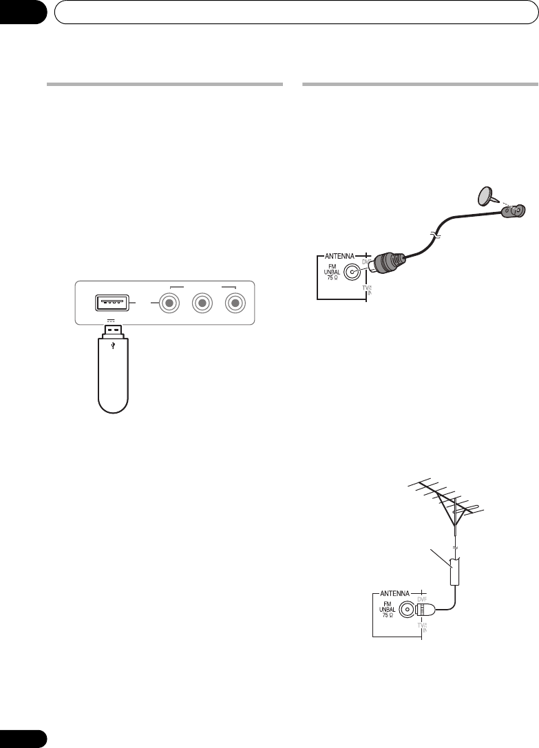
Connexions02
42
Fr
Branchement d’une clé USB
Il est possible de reproduire des fichiers en
faisant appel à l’interface USB sur l’avant de ce
système.
• Commutez le système en mode Veille,
puis brancez votre clé USB sur la borne
USB
,
prévue sur le panneau avant du système.
• Déposez le cache lorsque vous effectuez
des connexions sur le panneau avant.
• Pour des explications sur l’emploi de la clé
USB, reportez-vous à Utilisation d’une clé
USB page 57.
Branchement de l’antenne FM
Raccordez le fil d’antenne FM comme illustré
ci-après. Pour améliorer la réception et la
qualité des sons, branchez des antennes
externes (Reportez-vous à Connexion
d’antennes extérieures ci-dessous).
•
Enfoncez la fiche d’antenne FM
sur la broche
centrale de la prise d’antenne FM.
Pour obtenir de bons résultats, déployez
complètement l’antenne FM et fixez-la à un
mur ou au chambranle d’une porte. Ne laissez
pas pendre l’antenne et ne l’enroulez pas.
Connexion d’antennes extérieures
Pour améliorer la réception FM, raccordez une
antenne FM externe sur la borne FM UNBAL
75 Ω.
VIDEO INPUT
VIDEO
iPod
iPhone
AUDIOLR
5 V 0.5 A
USB
Périphérique de
stockage de
masse USB
75
Ω
Câble coaxial
HTP-710_VYXCN_Fr.book 42 ページ 2010年8月23日 月曜日 午後6時37分

Connexions 02
43
Fr
Français
Emploi des sorties PRE OUT pour
raccorder les enceintes surround
arrière
Raccordez les sorties PRE OUT de l’appareil et
un amplificateur supplémentaire afin d’ajouter
une enceinte surround arrière.
• Vous pouvez raccorder l’amplificateur
supplémentaire aux sorties “pre-out” de
canal surround arrière pour ajouter une
seule enceinte. Dans ce cas, branchez
l’amplificateur uniquementsur la borne
gauche (L (Single)).
Branchement du système
Ne raccordez le système au secteur qu’après y
avoir connecté tous les composants, y compris
les enceintes.
1 Branchez le cordon d’alimentation fourni
sur la prise
AC IN
à l’arrière du système.
2 Branchez l’autre extrémité sur une prise
secteur.
ATTENTION
• Tenez le cordon d’alimentation par sa
prise. Ne débranchez pas l’appareil en
tirant sur le cordon et ne touchez jamais le
cordon d’alimentation avec les mains
mouillées ; vous pourriez provoquer un
court-circuit ou subir un choc électrique.
Ne placez pas l’appareil, un meuble ou tout
autre objet sur le cordon d’alimentation et
évitez de le pincer de toute autre manière.
Ne faites jamais de noeud dans le cordon
et ne le liez jamais avec d’autres câbles.
Les cordons d’alimentation doivent être
acheminés de façon à ce qu’on ne puisse
pas les piétiner. Un cordon d’alimentation
endommagé peut provoquer un incendie
ou un choc électrique. Vérifiez l’état du
cordon de temps à autre. Si le cordon est
endommagé, demandez-en le
remplacement auprès du service après-
vente agréé Pioneer le plus proche.
• N’utilisez pas un cordon d’alimentation
autre que celui qui est fourni avec cet
appareil.
• N’utilisez pas le cordon d’alimentation
fourni à d’autres fins que celles décrites ci-
avant.
• Lorsque le système ne sera pas utilisé
durant une longue période (par ex. pendant
les vacances), il est recommandé de le
débrancher, en retirant la fiche du cordon
secteur.
1 2
ANALOG
RL
AUDIO IN
Amplificateur de canal
surround arrière
Enceintes surround arrière
SBL SBR
HTP-710_VYXCN_Fr.book 43 ページ 2010年8月23日 月曜日 午後6時37分

Lecture iPod/USB 05
55
Fr
Français
Chapitre 5
Lecture iPod/USB
Lecture par iPod
Cet appareil possède une borne iPod réservée
qui vous permet de gérer la lecture du contenu
audio sur votre iPod au moyen des
commandes de ce système.1
Important
• Lors d’une connexion à un téléviseur en
utilisant la sortie HDMI seulement, le Top
menu du iPod ne sera pas affiché. Dans ce
cas, utilisez une connexion composite à la
place.
1 Mettez le système et le téléviseur sous
tension.
Reportez-vous à Branchement d’un iPod/
iPhone page 41.
2 Appuyez sur la touche
iPod USB
pour
commuter le système au iPod/USB.
L’affichage du panneau avant indique Loading
pendant que le système vérifie la connexion et
récupère les données du iPod.
3 Utilisez la touche
TOP MENU
pour
afficher le Top menu du iPod.
Dès que l’affichage indique Top Menu, vous
être prêt à écouter la musique de l’iPod.2
• Si, après une pression sur iPod, l’écran
affiche NO DEVICE, déconnectez le
système et reconnectez l’iPod sur le
système.
Lecture de l’iPod
Pour naviguer dans les plages de musique de
votre iPod, vous pouvez utiliser la fonction
d’affichage sur écran (OSD) du téléviseur
raccordé à ce système.3 Vous pouvez
également commander toutes les fonctions
relatives à la musique à partir du panneau
avant de ce système.
Recherche des morceaux à écouter
Lorsque votre iPod est raccordé à ce système,
vous pouvez naviguer parmi les morceaux de
musique enregistrés sur votre iPod par listes
de lecture, artistes, albums, morceaux, genres
ou compositeurs, comme si vous utilisiez
directement votre iPod.
1 Utilisez les touches
/
pour
sélectionner une catégorie, puis appuyez sur
ENTER
pour naviguer dans cette catégorie.
• Pour revenir au niveau précédent à tout
moment, appuyez sur RETURN.
Remarque
1 • Ce système est compatible avec les signaux audio et vidéo des iPod nano, iPod 5e génération, iPod classic, iPod
touch et iPhone (iPod shuffle n’est pas pris en compte). Cependant, il se peut que certaines de ces fonctions soient
limitées sur certains modèles. Notez, toutefois, que la compatibilité peut varier selon la version du logiciel de votre
iPod ou de votre iPhone. Veillez à utiliser la version de logiciel la plus récente qui soit disponible.
• iPod et iPhone sous licence pour la reproduction de supports non soumis à des droits d’auteur ou de supports que
l’utilisateur a légalement le droit de reproduire.
• La fonction d’égalisation ne peut pas être commandée à l’aide de ce système. Nous recommandons donc de
désactiver l’égaliseur avant de connecter le système.
• Pioneer ne peut en aucun cas assumer de responsabilité pour toute perte directe ou indirecte résultant d’un
problème ou de la perte de matériel enregistré dus à une panne de l’iPod.
2 Les commandes de votre iPod (sauf iPod touch ou iPhone) seront désactivées lors d’une connexion à ce système
(Pioneer apparaît sur l’écran du iPod).
3 • Notez que les caractères non alphabétiques sont affichés comme .
• Cette fonction n’est pas disponibles pour les photos et les clips vidéo sur votre iPod.
iPod Top
[ Playlists ]
[ Artists ]
[ Albums ]
[ Songs ]
[ Podcasts ]
[
Genres ]
[ Composers ]
[ Audiobooks ]
[ Shuffle Songs ]
ENTER
HTP-710_VYXCN_Fr.book 55 ページ 2010年8月23日 月曜日 午後6時37分

Lecture iPod/USB05
56
Fr
2 Utilisez les touches
/
pour naviguer
dans la catégorie sélectionnée (par ex. les
albums).
•Utilisez / pour passer au niveau
précédent/suivant.
3 Continuez à naviguer jusqu’à ce que vous
arriviez au morceau à écouter, puis appuyez
sur
pour commencer la lecture.
1
La navigation dans les catégories sur votre
iPod se présente de la manière suivante :
Playlists Songs
Artists Albums Songs
Albums Songs
Songs
Podcasts
Genres Artists Albums Songs
Composers Albums Songs
Audiobooks
Shuffle Songs
Note
• Vous pouvez lire toutes les chansons d’une
catégorie particulière en sélectionnant
l’option All, figurant en haut de chaque
liste de catégorie. Par exemple, vous
pouvez lire tous les morceaux d’un artiste
particulier.
Commandes de base pour la lecture
Le tableau suivant présente les commandes de
lecture de base pour votre iPod : Appuyez sur
iPod USB pour faire passer la télécommande
au mode de fonctionnement iPod.
Visualisation de photos et de
contenu vidéo
Pour visualiser des photos ou une vidéo sur
votre iPod, comme ce système ne permet pas
la commande vidéo, vous devez utiliser les
commandes principales de votre iPod.2
Remarque
1 Si vous êtes dans la catégorie Morceaux, vous pouvez aussi appuyer sur ENTER pour commencer la lecture.
Touches Leur fonction
Appuyez pour lancer la lecture.
Si vous lancez la lecture alors qu’un
élément autre qu’une plage est
sélectionnée, toutes les chansons
de cette catégorie seront lues.
ENTER Appuyez pour régler les modes de
lecture et de pause.
Pour interrompre la lecture ou la
reprendre quand elle a été
interrompue.
/ Maintenez enfoncé pendant la
lecture pour lancer l’exploration.
/ Appuyez pour passer à la plage
précédente/suivante.
Appuyez pour passer
successivement à Repeat One,
Repeat All et Repeat Off.
Appuyez pour passer
successivement à Shuffle Songs,
Shuffle Albums et Shuffle Off.
DISPLAY Appuyez de façon répétée pour
changer les informations de lecture
de chanson, affichées sur l’écran du
panneau avant.
/Pendant la navigation, appuyez pour
passer au niveau précédent/suivant.
/ Pendant la lecture d’un livre audio
(Audiobook), permet de modifier la
vitesse de lecture : Plus rapide
Normale Plus lente
TOP
MENU
Appuyez pour revenir à l’affichage
du menu iPod Top.
RETURN Permet de revenir au niveau
précédent.
2 • Vous ne pouvez regarder les photos iPods et le contenu vidéo que si l’iPod est raccordé à l’entrée iPod VIDEO sur
le panneau avant.
• Cette fonction est disponible uniquement si votre iPod possède une sortie vidéo.
Touches Leur fonction
HTP-710_VYXCN_Fr.book 56 ページ 2010年8月23日 月曜日 午後6時37分

Lecture iPod/USB 05
57
Fr
Français
Important
• Pour lire des photos ou une vidéo sur votre
iPod, vous devez raccorder la prise
MONITOR OUT composite et le téléviseur.
Les photos et le contenu vidéo
n’apparaîtront pas si vous avez fait la
connexion par la sortie HDMI sur votre
téléviseur.
1 Appuyez sur
iPod CTRL
pour sélectionner
les commandes iPod, autorisant la lecture de
photos et de vidéo.
Les commandes du système ne sont pas
disponibles pendant que vous regardez des
vidéos sur votre iPod ou que vous parcourez
une liste de photos.
2 Appuyez à nouveau sur
iPod CTRL
pour
réactiver les commandes du système lorsque
vous avez terminé.
À
propos de l’iPod/iPhone
Les accessoires é lectroniques portant la
mention « Made for iPod » et « Made for iPhone »
ont été conçus pour fonctionner
respectivement avec un iPod ou un iPhone et
sont certifiés conformes aux exigences
d’Apple par le fabricant. Apple n’est pas
responsable pour le fonctionnement de cet
appareil ou de sa compatibilité é avec les
normes ré glementaires et de sécurité.
iPod et iPhone sont des marques commerciales
d’Apple Inc., déposées aux États-Unis et dans
d’autres pays.
Utilisation d’une clé USB
L’interface USB située à l’avant de cet appareil
permet d’écouter un contenu audio à 2 voies.1
Important
• Lors d’une connexion à un téléviseur par la
sortie HDMI seule, la fenêtre de lecture
USB sur l’affichage sur écran n’apparaît.
Dans ce cas, utilisez une connexion
composite à la place.
1 Mettez le système et le téléviseur sous
tension.
2 Appuyez sur
iPod USB
de la
télécommande pour commuter le système au
iPod/USB.
No Device apparaît sur l’affichage à l’écran.
Remarque
1 Ceci inclut la lecture de fichiers WMA/MP3/MPEG-4 AAC (à l’exception des fichiers enregistrés avec une protection
contre la copie ou limitant la possibilité de lecture).
HTP-710_VYXCN_Fr.book 57 ページ 2010年8月23日 月曜日 午後6時37分

Lecture iPod/USB 05
59
Fr
Français
Pour plus d’informations sur les messages
d’erreur, consultez Messages USB page 88.
Si cela ne résout pas le problème, il y estfort
probable que votre périphérique USB ne soit
pas compatible.
Compatibilité des fichiers audio
compressés
Notez que, bien que la plupart des
combinaisons standard de débit binaire/taux
d’échantillonnage pour les fichiers audio
compressés soient compatibles, certains
fichiers codés irrégulièrement risquent de ne
pas pouvoir être lus. La liste suivante indique
les formats de fichiers audio compressés
compatibles :
•MP3 (MPEG-1/2/2.5 Audio Layer 3) – Taux
d’échantillonnage : 8 kHz à 48 kHz ; Débits
binaires : 8 kbps à 320 kbps (128 kbps
minimum recommandés) ; Extension de
fichier : .mp3
•WMA (Windows Media Audio) – Taux
d’échantillonnage : 32 kHz / 44,1 kHz ;
Débits binaires : 32 kbps à 192 kbps (128
kbps minimum recommandés) ; Extension
de fichier : .wma ; Encodage sans perte
WMA9 Pro et WMA : Non
•AAC (MPEG-4 Advanced Audio Coding) –
Taux d’échantillonnage : 11,025 kHz à 48
kHz ; Débits binaires : 16 kbps à 320 kbps
(128 kbps minimum recommandés) ;
Extension de fichier : .m4a ; Encodage
sans perte Apple : Non
Autres informations sur la compatibilité
• Lecture des fichiers MP3/WMA/MPEG-4
AAC à taux binaire variable (VBR) : Oui1
• Compatibilité avec la protection DRM
(Digital Rights Management) : Oui (les
fichiers audio à protection DRM ne pourront
pas être lus par ce système).
À propos de la norme MPEG-4 AAC
Advanced Audio Coding (AAC) est au coeur de
la norme MPEG-4 AAC, qui intègre MPEG-2
AAC, formant ainsi la base de la technologie de
compression audio MPEG-4. Le format et
l’extension de fichier dépendent de
l’application utilisée pour coder le fichier AAC.
Cet appareil peut lire les fichiers AAC codés
avec iTunes, portant l’extension ‘.m4a’. Les
fichiers utilisant une protection DRM contre la
copie ne sont pas lisibles et il se peut que des
fichiers codés avec certaines versions de
iTunes ne soient pas lisibles.
Apple et iTunes sont des marques
commerciales d’Apple Inc., enregistrées aux
États-Unis et d’autres pays.
À propos de WMA
Le logo Windows Media imprimé sur le coffret
indique que cet appareil peut lire les fichiers
Windows Media Audio.
WMA est le sigle de Windows Media Audio,
une technique de compression audio mise au
point par Microsoft Corporation. Cet appareil
peut lire les fichiers WMA codés avec Windows
Media® Player, portant l’extension ‘.wma’. Les
fichiers utilisant une protection DRM ne sont
pas lisibles, et il se peut que certains fichiers
codés avec certaines versions de Windows
Media® Player ne soient pas lisibles.
Windows Media et le logo Windows sont des
marques commerciales ou des marques
déposées de Microsoft Corporation aux États-
Unis et/ou dans d’autre pays.
Remarque
1 Notez que, dans certains cas, la durée de lecture ne sera pas affichée correctement.
HTP-710_VYXCN_Fr.book 59 ページ 2010年8月23日 月曜日 午後6時37分
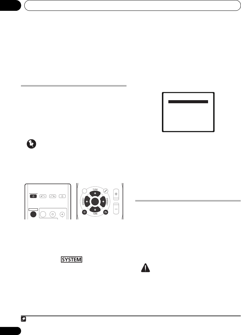
Menu de configuration du système08
72
Fr
Chapitre 8
Menu de configuration du
système
Utilisation du menu de
configuration du système
La section suivante décrit de façon détaillée
comment effectuer les réglages adaptés à
votre propre utilisation du système et comment
régler séparément chaque système
d’enceintes selon vos exigences.
Important
• L’affichage sur écran (OSD) n’apparaîtra
pas si vous avez fait la connexion par la
sortie HDMI sur votre téléviseur. Utilisez
les connexions composites pour la
configuration du système.
1 Mettez le système et le téléviseur sous
tension.
Utilisez la touche SYSTEM pour ce faire.
Réglez l’entrée du téléviseur de sorte qu’elle
connecte le système en mode analogique.
2 Appuyez sur de la
télécommande, puis appuyez sur la touche
SETUP
.
1
Un affichage sur écran (OSD) apparaît sur votre
téléviseur. Utilisez les touches
///
et
ENTER
de la télécommande pour naviguer sur
les écrans et choisir les paramètres des menus.
Appuyez sur
RETURN
pour valider la sélection
et quitter le menu actuel.
3 Sélectionnez le réglage souhaité.
•Auto MCACC – Il s’agit d’une
configuration surround automatique
rapide et efficace (Reportez-vous à
Configuration automatique du son
surround (MCACC) page 51).
•Manual SP Setup – Définit le nombre, la
distance et la balance générale des
enceintes que vous avez raccordées
(Reportez-vous à Configuration manuelle
des enceintes ci-dessous).
Configuration manuelle des
enceintes
Ces réglages sont destinés à optimiser les
performances de votre système, mais si vous
êtes satisfait des réglages effectués par
Configuration automatique du son surround
(MCACC) page 51, vous pouvez décider d’en
ignorer certains.
ATTENTION
• Les tonalités d’essai utilisées pour la
configuration du système ont un volume
élevé.
Remarque
1 • Vous ne pouvez pas utiliser le menu de configuration du système lorsque l’entrée iPod/USB est sélectionnée.
• Appuyez sur SETUP à tout moment pour quitter le menu configuration du système.
TOP
MENU
HOME
MENU
PTY SEARCH
AUDIO
PARAMETER
iPod CTRL
MASTER
VOLUME
TOOLS
MENU
RETURN
ST/MONO
SETUP
ENTER
TV CONTROL
CH
INPUT
INPUT SELECT SOURCE
SYSTEM
SYSTEM
TUNER EDIT
System Setup
1.Auto MCACC
2.Manual SP Setup
Return
HTP-710_VYXCN_Fr.book 72 ページ 2010年8月23日 月曜日 午後6時37分

Menu de configuration du système 08
73
Fr
Français
1 Sélectionnez ‘Manual SP Setup’, puis
appuyez sur la touche
ENTER
.
2 Sélectionnez le réglage souhaité.
Si vous effectuez ces réglages pour la première
fois, il est préférable de respecter l’ordre
suivant :
•Speaker Setting – Permet d’indiquer le
nombre d’enceintes connectées (cf.ci-
après).
•Channel Level – Réglez l’équilibre global
de votre système d’enceintes (cf.ci-après).
•Speaker Distance – Pour préciser la
distance entre les enceintes et la position
d’écoute (Reportez-vous à page 74).
3 Effectuez les ajustements nécessaires
pour chaque réglage en appuyant sur
RETURN
pour confirmer après chaque écran.
Réglage des enceintes
Utilisez ce réglage pour effectuer la
configuration des enceintes (nombre
d’enceintes). C’est une bonne idée de
s’assurer que les réglages faits dans la section
Configuration automatique du son surround
(MCACC) page 51 sont corrects.
1 Sélectionnez ‘Speaker Setting’ dans le
menu Manual SP Setup.
2 Choisissez le jeu d’enceintes à régler, puis
sélectionnez un paramètre d’enceinte.
Utilisez / pour sélectionner le nombre de
chacune des enceintes suivantes :
•Front – Ce paramètre ne peut pas être
modifié car il est déjà optimisé pour cet
appareil.
•Center – Sélectionnez SMALL si vous
raccordez une enceinte centrale. Si vous
n’avez pas connecté d’enceinte centrale,
choisissez NO (le canal central est envoyé
vers les autres enceintes).
•Surr – Sélectionnez SMALL si vous
raccordez des enceintes surround. Si vous
n’avez pas connecté d’enceintes surround,
choisissez NO (le son des canaux surround
est envoyé vers les autres enceintes).
•Surr. Back – Sélectionnez le nombre
d’enceintes surround arrière que vous avez
(une, deux ou zéro).1 Si vous n’avez pas
raccordé d’enceintes surround arrière,
choisissez NO.
•Subwoofer – Ce paramètre ne peut pas
être modifié car il est déjà optimisé pour
cet appareil.
3 Quand vous avez terminé, appuyez sur
RETURN
.
Vous pouvez revenir au menu Configuration
manuel des enceintes.
Note
Pour le HTP-FS510 :
Si des enceintes en option ne sont pas
raccordées, réglez Center et Surr à la position
NO.
Pour le HTP-SB510 :
Si des enceintes en option ne sont pas
raccordées, réglez Surr à la position NO.
Niveau des canaux
À l’aide des paramètres de niveau des canaux,
vous pouvez régler la balance générale de votre
système d’enceintes, un facteur important lors
du réglage de votre système de Home Cinéma.
System Setup
1.Auto MCACC
2.Manual SP Setup
Return
2.Manual SP Setup
Return
a.Speaker Setting
b.Channel Level
c.Speaker Distance
2.Manual SP Setup
Return
a.Speaker Setting
b.Channel Level
c.Speaker Distance
2a.Speaker Setting
Front
Center
Surr
Surr. Back
Subwoofer:
Return
[ SMALL ]
[ SMALL ]
[ NO ]
YES
SMALL
Remarque
1 • Si les enceintes surround sont réglées sur NO, les enceintes surround arrière sont automatiquement réglées sur
NO.
• Si vous ne sélectionnez qu’une seule enceinte surround arrière, assurez-vous que l’amplificateur supplémentaire
est raccordé à la borne PRE OUT SURROUND BACK L (Single).
HTP-710_VYXCN_Fr.book 73 ページ 2010年8月23日 月曜日 午後6時37分

Commande des autres fonctions du système 09
75
Fr
Français
Chapitre 9
Commande des autres fonctions
du système
Préparation de la télécommande
pour gérer d’autres composants
La plupart des composants peuvent être
attribués à l’une des touches MULTI
CONTROL en utilisant le code de préréglage
du fabricant du composant, stocké dans la
télécommande.
Cependant, sachez qu’il existe des cas où
seulement certaines fonctions peuvent être
contrôlées après affectation du code de
préréglage adéquat ou bien les codes pour
fabricant se trouvant dans la télécommande ne
fonctionneront pas pour le modèle que vous
utilisez.1
Remarque
• Pour annuler ou abandonner une des
démarches, maintenez la touche
enfoncée.
• Au bout d’une minute d’inactivité, la
télécommande quitte automatiquement
l’opération.
Sélection directe des codes de
préréglage
1 Tout en appuyant sur la touche ,
maintenez la touche ‘
1
’ enfoncée pendant trois
secondes.
2 Appuyez sur la touche
MULTI CONTROL
pour sélectionner le composant à contrôler.
Le composant peut être attribué à la touche
BD, TV, DVR ou VIDEO.
3 Utilisez les touches numériques pour
saisir le code de préréglage.
Vous trouverez les codes de préréglage à
page 79.
Si vous avez saisi le code correct, le composant
raccordé se met sous ou hors tension.
La mise sous ou hors tension n’a lieu que si le
composant peut être directement allumé par la
télécommande.
4 Répétez les étapes 2 et 3 pour essayer un
autre code ou saisir un code pour un autre
composant à contrôler.
5 Quand vous avez terminé, appuyez sur
.
Suppression de tous les réglages
de la télécommande
Vous pouvez effacer tous les préréglages et
rétablir les paramètres définis en usine.
• Tout en appuyant sur la touche ,
maintenez la touche ‘0’ enfoncée pendant trois
secondes.
Remarque
1 Les codes de commande de téléviseur (par ex. téléviseur, télévision par câble, par satellite ou téléviseur numérique)
peuvent uniquement être affectés à la touche TV.
SYSTEM TV CONTROL
CH
INPUT
DISPLAY
CH
CH
EQ
PHASESB CH
CH SELECT
SLEEP
ENTER
MIDNGIHT
S.RETRIEVER
HDD DVD VCR
SHIFT
HTP-710_VYXCN_Fr.book 75 ページ 2010年8月23日 月曜日 午後6時37分

Commande des autres fonctions du système09
76
Fr
Codes de préréglages par défaut
Commandes pour téléviseurs
Cette télécommande peut gérer des composants après saisie des codes adéquats ou après avoir
enseigné les commandes au système (Reportez-vous à Commande des autres fonctions du
système page 75 pour en savoir plus). Utilisez les touches MULTI CONTROL pour sélectionner le
composant.
• Les touches TV CONTROL de la télécommande sont destinées à gérer le téléviseur, attribué à
la touche TV.
Touche MULTI
CONTROL
Code de
préréglage
BD 2126
TV 0120
DVR 2121
VIDEO 1120
Touche(s) Fonction Composants
TV CONTROL
Allume ou éteint le DTV. DTV
Pour mettre le téléviseur ou la télévision par câble sous
tension ou en mode Veille.
Téléviseur câblé/Téléviseur
Satellite/Téléviseur
TV CONTROL
INPUT
Commute l’entrée téléviseur. (Pas possible avec tous
les modèles.)
Téléviseur
TV CONTROL
CH +/–
Sélectionne les chaînes. Téléviseur câblé/Téléviseur
Satellite/Téléviseur/DTV
TV CONTROL
VOL +/–
Ajuste le volume du téléviseur. Téléviseur câblé/Téléviseur
Satellite/Téléviseur/DTV
SOURCE Appuyez pour mettre le composant attribué à la touche
TV en service ou hors service.
Téléviseur câblé/Téléviseur
Satellite/Téléviseur/DTV
DTV/TV Permute entre les modes d’entrée DTV et Téléviseur
analogique pour les téléviseurs de Pioneer.
DTV/Téléviseur
TOP MENU Active ou désactive TEXT ON/OFF pour les téléviseurs. Téléviseur
HOME MENU Utilisez comme touche GUIDE pour la navigation. Téléviseur câblé/Téléviseur
Satellite/Téléviseur/DTV
RETURN Permet de sélectionner le sous-titrage codé avec la
DTV.
DTV
Touc he s
numériques
Pour sélectionner un chaîne de télévision particulière. Téléviseur câblé/Téléviseur
Satellite/Téléviseur/DTV
Touc he +10 Pour ajouter des décimales lors de la sélection d’une
chaîne de télévision.
DTV
HTP-710_VYXCN_Fr.book 76 ページ 2010年8月23日 月曜日 午後6時37分

Commande des autres fonctions du système09
80
Fr
Téléviseur
Fabricant Code
A.R. Systems 0040
Acme 0026
Acura 0027, 0039
ADC 0025
Admiral 0023, 0024, 0025,
0030, 0031
Adyson 0026, 0113, 0114
Agashi 0113, 0114
Agazi 0025
Aiko 0026, 0027, 0039,
0040, 0113, 0114
Aim 0040
Aiwa 0084
Akai 0027, 0028, 0034,
0037, 0039, 0040, 0113,
0114
Akiba 0028, 0040
Akura 0025, 0028, 0039,
0040
Alaron 0113
Alba 0010, 0026, 0027,
0028, 0032, 0035, 0037,
0039, 0040, 0075, 0078,
0088, 0113
Alcyon 0017
Allorgan 0114
Allstar 0034, 0040
AMOi 0109
Amplivision 0010, 0026,
0041, 0114
Amstrad 0025, 0027, 0028,
0039, 0040
Anam 0027
Anglo 0027, 0039
Anitech 0017, 0025, 0027,
0039, 0040
Ansonic 0010, 0018, 0027,
0029, 0039, 0040
Arcam 0113, 0114
Arcam Delta 0026
Aristona 0034, 0037, 0040
Arthur Martin 0041
ASA 0023, 0031
Asberg 0017, 0034, 0040
Astra 0027
Asuka 0025, 0026, 0028,
0113, 0114
Atlantic 0026, 0034, 0037,
0040, 0113
Atori 0027, 0039
Auchan 0041
Audiosonic 0010, 0026,
0027, 0028, 0034, 0037,
0040, 0114
AudioTon 0010, 0026, 0114
Ausind 0017
Autovox 0017, 0023, 0025,
0026, 0114
Awa 0113, 0114
Baird 0114
Bang & Olufsen 0023,
0115
Basic Line 0027, 0028,
0034, 0039, 0040, 0114
Bastide 0026, 0114
Baur 0037, 0040
Bazin 0114
Beko 0010, 0035, 0040,
0060
Benq 0104
Beon 0034, 0037, 0040
Best 0010
Bestar 0010, 0034, 0040
Binatone 0026, 0114
Blue Sky 0028, 0040
Blue Star 0036
Boots 0026, 0114
BPL 0036, 0040
Brandt 0033, 0038, 0042,
0044
Brinkmann 0040
Brionvega 0023, 0034,
0037, 0040
Britannia 0026, 0113, 0114
Bruns 0023
BTC 0028
Bush 0027, 0028, 0030,
0032, 0034, 0036, 0037,
0039, 0040, 0065, 0078,
0114
Capsonic 0025
Carena 0040
Carrefour 0032
Cascade 0027, 0039, 0040
Casio 0106
Cathay 0034, 0037, 0040
CCE 0114
Centurion 0034, 0037, 0040
Century 0023
CGE 0010, 0017
Cimline 0027, 0039
City 0027, 0039
Clarivox 0037
Clatronic 0010, 0017, 0025,
0026, 0027, 0028, 0034,
0035, 0039, 0040, 0114
CMS 0113
CMS Hightec 0114
Concorde 0027, 0039
Condor 0010, 0026, 0034,
0035, 0039, 0040, 0113
Contec 0026, 0027, 0032,
0039, 0113
Continental Edison 0033
Cosmel 0027, 0039
Crosley 0017, 0023
Crown 0010, 0017, 0027,
0034, 0035, 0037, 0039,
0040
CS Electronics 0026, 0028,
0113
CTC Clatronic 0029
Cybertron 0028
Daewoo 0013, 0026, 0027,
0034, 0039, 0040, 0054,
0064, 0091, 0113, 0114
Dainichi 0028, 0113
Dansai 0025, 0034, 0037,
0040, 0113, 0114
Dantax 0010, 0037
Dawa 0040
Daytron 0027, 0039
De Graaf 0030
Decca 0026, 0034, 0037,
0040, 0114
Denver 0098, 0103
Desmet 0034, 0037, 0040
Diamant 0040
Diamond 0113
Dixi 0027, 0034, 0037, 0039,
0040, 0114
DTS 0027, 0039
Dual 0026, 0040, 0114
Dual-Tec 0026, 0027
Dumont 0023, 0026, 0029,
0114
Dux 0037
Dynatron 0034, 0037, 0040
Elbe 0010, 0018, 0040, 0114
Elcit 0023
Electa 0036
ELECTRO TECH 0027
Elin 0026, 0034, 0037, 0039,
0040, 0113
Elite 0028, 0034, 0040
Elman 0029
Elta 0027, 0039, 0113
Emerson 0010, 0023, 0040
Epson 0101
Erres 0034, 0037, 0040
ESC 0114
Etron 0027
Eurofeel 0025, 0114
Euroline 0037
Euroman 0010, 0025, 0026,
0034, 0040, 0113, 0114
Europhon 0026, 0029,
0034, 0040, 0113, 0114
Expert 0041
Exquisit 0040
Fenner 0027, 0039
Ferguson 0033, 0037, 0038,
0042
Fidelity 0026, 0030, 0040,
0113
Filsai 0114
Finlandia 0030
Finlux 0017, 0023, 0026,
0029, 0034, 0037, 0040,
0114
Firstline 0026, 0027, 0034,
0039, 0040, 0113, 0114
Fisher 0010, 0023, 0026,
0032, 0035, 0114
Flint 0034, 0040
Formenti 0017, 0023, 0024,
0026, 0037, 0113
Formenti/Phoenix 0113
Fortress 0023, 0024
Fraba 0010, 0040
Friac 0010
Frontech 0025, 0027, 0030,
0031, 0039, 0114
Fujitsu 0114
Fujitsu General 0114
Funai 0025
Galaxi 0035, 0040
Galaxis 0010, 0040
GBC 0027, 0032, 0039
Geant Casino 0041
GEC 0026, 0031, 0034, 0037,
0040, 0114
Geloso 0027, 0030, 0039
General Technic 0027,
0039
Genexxa 0028, 0031, 0034,
0040
Giant 0114
GoldHand 0113
Goldline 0040
GoldStar 0010, 0026, 0027,
0030, 0034, 0037, 0039,
0040, 0113, 0114
Goodmans 0025, 0027,
0032, 0034, 0037, 0039,
0040, 0107, 0114
Gorenje 0010, 0035
GPM 0028
Graetz 0031
Granada 0017, 0026, 0030,
0032, 0034, 0037, 0040,
0041, 0114
Grandin 0027, 0028, 0036,
0037
Gronic 0114
HTP-710_VYXCN_Fr.book 80 ページ 2010年8月23日 月曜日 午後6時37分

Commande des autres fonctions du système 09
83
Fr
Français
Basic Line 1002, 1003,
1004, 1007, 1017, 1018
Baur 1006
Bestar 1003, 1004, 1018
Black Panther Line 1003,
1018
Blaupunkt 1006
Bondstec 1004, 1017
Bush 1002, 1003, 1007,
1017, 1018
Cathay 1018
Catron 1004
CGE 1000, 1001
Cimline 1002, 1007, 1017
Clatronic 1004, 1017
Condor 1003, 1004, 1018
Crown 1003, 1004, 1007,
1017, 1018
Daewoo 1003, 1004, 1018
Dansai 1007, 1017, 1018
Dantax 1002
Daytron 1003, 1018
De Graaf 1006
Decca 1000, 1001, 1006
Denko 1017
Dual 1001, 1006, 1018
Dumont 1000, 1006
Elbe 1018
Elcatech 1017
Elsay 1017
Elta 1007, 1017, 1018
Emerson 1017
ESC 1003, 1018
Etzuko 1007, 1017
Ferguson 1001
Fidelity 1000, 1017
Finlandia 1006
Finlux 1000, 1001, 1006
Firstline 1002, 1005, 1007,
1017
Flint 1002
Formenti/Phoenix 1006
Frontech 1004
Fujitsu 1000
Funai 1000
Galaxy 1000
GBC 1004, 1007
GEC 1006
Geloso 1007
General 1004
General Technic 1002
GoldHand 1007, 1017
GoldStar 1000, 1005
Goodmans 1000, 1003,
1004, 1005, 1007, 1017,
1018
Graetz 1001
Granada 1006
Grandin 1000, 1003, 1004,
1005, 1007, 1017, 1018
Grundig 1006, 1007
Hanseatic 1005, 1006, 1018
Harwood 1017
HCM 1007, 1017
Hinari 1002, 1007, 1017,
1018
Hisawa 1002
Hitachi 1000, 1001, 1006,
1012
Hypson 1002, 1007, 1017,
1018
Impego 1004
Imperial 1000
Inno Hit 1003, 1004, 1006,
1007, 1017, 1018
Innovation 1002
Interbuy 1005, 1017
Interfunk 1006
Intervision 1000, 1018
Irradio 1005, 1007, 1017
ITT 1001
ITV 1003, 1005, 1018
JVC 1001, 1013
Kaisui 1007, 1017
Karcher 1006
Kendo 1002, 1003, 1004,
1017
Kenwood 1001
Korpel 1007, 1017
Kyoto 1017
Lenco 1003
Leyco 1007, 1017
LG 1000, 1005, 1016
Lifetec 1002
Loewe Opta 1005, 1006
Logik 1007, 1017
Lumatron 1003, 1018
Luxor 1017
M Electronic 1000
Manesth 1007, 1017
Marantz 1006
Mark 1018
Matsui 1002, 1005
Mediator 1006
Medion 1002
Memorex 1000, 1005
Memphis 1007, 1017
Micromaxx 1002
Microstar 1002
Migros 1000
Mitsubishi 1000, 1006
Multitech 1000, 1004,
1006, 1007, 1017
Murphy 1000
NEC 1001
Neckermann 1001, 1006
NEI 1006
Nesco 1007, 1017
Nikkai 1004, 1017, 1018
Nokia 1001, 1018
Nordmende 1001
Oceanic 1000, 1001
Okano 1002, 1017, 1018
Orion 1002
Orson 1000
Osaki 1000, 1005, 1007,
1017
Otto Versand 1006
Palladium 1001, 1005,
1007, 1017
Panasonic 1010
Pathe Marconi 1001
Perdio 1000
Philco 1017
Philips 1006, 1012, 1019
Phonola 1006
Pioneer 1006, 1120
Portland 1003, 1004, 1018
Prinz 1000
Profex 1007
Proline 1000
Prosonic 1002, 1018
Pye 1006
Quelle 1000, 1006
Radialva 1017
Radiola 1006
Rex 1001
RFT 1004, 1006, 1017
Roadstar 1003, 1005, 1007,
1017, 1018
Royal 1017
Saba 1001
Saisho 1002, 1007
Samsung 1008
Samurai 1004, 1017
Sansui 1001
Saville 1018
SBR 1006
Schaub Lorenz 1000, 1001
Schneider 1000, 1002,
1003, 1004, 1005, 1006,
1007, 1017, 1018
SEG 1007, 1017, 1018
SEI-Sinudyne 1006
Seleco 1001
Sentra 1004, 1017
Sentron 1007, 1017
Sharp 1009
Shintom 1007, 1017
Shivaki 1005
Siemens 1005
Silva 1005
Silver 1018
Sinudyne 1006
Solavox 1004
Sonneclair 1017
Sonoko 1003, 1018
Sontec 1005
Sony 1011
Standard 1003, 1018
Stern 1018
Sunkai 1002
Sunstar 1000
Suntronic 1000
Sunwood 1007, 1017
Symphonic 1017
Taisho 1002
Tandberg 1018
Tashiko 1000
Tatung 1000, 1001, 1006
TCM 1002
Teac 1018
Tec 1004, 1017, 1018
Teleavia 1001
Telefunken 1001
Teletech 1017, 1018
Tenosal 1007, 1017
Tensai 1000, 1005, 1007,
1017
Tevion 1002
Thomson 1001, 1015
Thorn 1001
Tokai 1005, 1007, 1017
Tonsai 1007
Toshiba 1001, 1006, 1014
Towada 1007, 1017
Towika 1007, 1017
TVA 1004
Uher 1005
Ultravox 1018
United Quick Star 1003,
1018
Universum 1000, 1005,
1006
Videon 1002
Weltblick 1005
Yamishi 1007, 1017
Yokan 1007, 1017
Yoko 1004, 1005, 1007,
1017
HTP-710_VYXCN_Fr.book 83 ページ 2010年8月23日 月曜日 午後6時37分

Informations complémentaires 10
89
Fr
Français
Caractéristiques techniques
Caisson de basses à récepteur SX-
SWR2
• Section audio
Puissance nominale de sortie
Avant, Centrale, Surround . . . . 100 W par voie
(1 kHz, 4
Ω
, 10 %)
Caisson de graves . . 100 W (100 Hz, 4
Ω
, 10 %)
• Section syntoniseur FM
Gamme de fréquences . . . . 87,5 MHz à 108 MHz
Entrée d’antenne . . . . . . . . . . 75 Ω, non équilibré
• Section Entrée/Sortie
Borne HDMI :
Entrée . . . . . . . . . . . . . . . . . . . . . 19 broches x3
Sortie . . . . . . . . . . . . 19 broches (5 V, 100 mA)
Entrée audio
. . . . . . . . . . .Coaxiale x1, Optique x2 (Numérique)
RCA (2 broches) x4 (Analogique)
Sortie audio . . . RCA (2 broches) x2 (Analogique)
Entrée vidéo . . . . . . . . . . . . . . . . . . . . . . . . RCA x3
Sortie vidéo. . . . . . . . . . . . . . . . . . . . . . . . . RCA x2
Entrée MCACC. . . . . . . . . . . . . . . . . . . . Mini prise
Borne iPod . . . . . . . . . USB + Vidéo (Composite)
• Section Enceintes
Boîtier . . . . . . . type installation au sol bass-reflex
Système . . . . . . . . . . . système à 1 voie de 16 cm
Haut-parleurs . . . . . . . . . type à cône de 16 cm x1
Impédance . . . . . . . . . . . . . . . . . . . . . . . . . . . . .4 Ω
Gamme de fréquences . . . . . . . .35 Hz à 1 000 Hz
• Divers
Alimentation. . . . . CA 220 V à 240 V, 50 Hz/60 Hz
Consommation . . . . . . . . . . . . . . . . . . . . . . . 61 W
En veille . . . . . . . . . . . . . . . . . . . . . . . . . . . . . 0,5 W
Dimensions
. . . . . 230 mm (L) x 360,5 mm (H) x 422,5 mm (P)
Poids (sans emballage). . . . . . . . . . . . . . . . . 11 kg
• Accessoires
Télécommande . . . . . . . . . . . . . . . . . . . . . . . . . . .1
Piles (taille AAA, IEC R03). . . . . . . . . . . . . . . . . . .2
Câble vidéo. . . . . . . . . . . . . . . . . . . . . . . . . . . . . . .1
Câble optique numérique . . . . . . . . . . . . . . . . . . .1
Câble iPod . . . . . . . . . . . . . . . . . . . . . . . . . . . . . . .1
Antenne filaire FM . . . . . . . . . . . . . . . . . . . . . . . .1
Microphone (pour la configuration Auto MCACC)
. . 1
Cordons d’alimentation . . . . . . . . . . . . . . . . . . . . 2
Grands coussinets antidérapants (pour caissons
de basses à récepteur). . . . . . . . . . . . . . . . . . . . . 4
Carte de garantie . . . . . . . . . . . . . . . . . . . . . . . . . 1
Mode d’emploi (ce document)
Enceinte S-DV595T (HTP-710)
• Enceintes avant/surround
Boîtier . . . type installation au sol à boîtier fermé
(à blindage magnétique)
Système. . . . . . . . . . . . . . . système bidirectionnel
Haut-parleurs :
Graves . . . . . . . . . . . . . . . . . type à cône 7,7 cm
Haut-parleur d’aigus
. . type demi-dôme 2,6 cm
Impédance . . . . . . . . . . . . . . . . . . . . . . . . . . . . 4 Ω
Gamme de fréquences . . . . . . . . .62 Hz à 20 kHz
Dimensions . .260 mm (L) x 1097 mm (H) x 260 mm (P)
Poids . . . . . . . . . . . . . . . . . . . . . . . . . . . . . . . 3,8 kg
• Enceinte centrale
Boîtier . . . . . . . type pour étagère à boîtier fermé
(à blindage magnétique)
Système. . . . . . . . . . . système à 1 voie de 7,7 cm
Haut-parleurs . . . . . . . . . . .type à cône de 7,7 cm
Impédance . . . . . . . . . . . . . . . . . . . . . . . . . . . . 4 Ω
Gamme de fréquences . . . . . . . . .72 Hz à 20 kHz
Dimensions
. . . . . . . . . 220 mm (L) x 90 mm (H) x 100 mm (P)
Poids . . . . . . . . . . . . . . . . . . . . . . . . . . . . . . . 0,7 kg
• Accessoires
Câbles d’enceinte. . . . . . . . . . . . . . . . . . . . . . . . . 5
Bases pour support de haut-parleur. . . . . . . . . . 4
Vis . . . . . . . . . . . . . . . . . . . . . . . . . . . . . . . . . . . . 12
Petits coussinets antidérapants
(pour bases de support d’enceinte) . . . . . . . . . 16
Enceinte S-SWR600 (HTP-610)
• Enceintes avant/surround
Boîtier . . . . . . . type pour étagère à boîtier fermé
(à blindage magnétique)
Système. . . . . . . . . . . système à 1 voie de 6,6 cm
Haut-parleurs . . . . . . . . . . .type à cône de 6,6 cm
Impédance . . . . . . . . . . . . . . . . . . . . . . . . . . . . 4 Ω
Gamme de fréquences . . . . . . . . .82 Hz à 20 kHz
Dimensions
. . . . . . . . . . . 96 mm (L) x 96 mm (H) x 96 mm (P)
Poids . . . . . . . . . . . . . . . . . . . . . . . . . . . . . . . 0,5 kg
HTP-710_VYXCN_Fr.book 89 ページ 2010年8月23日 月曜日 午後6時37分

Informations complémentaires10
90
Fr
• Enceinte centrale
Boîtier. . . . . . . . type pour étagère à boîtier fermé
(à blindage magnétique)
Système . . . . . . . . . . . système à 1 voie de 6,6 cm
Haut-parleurs . . . . . . . . . . type à cône de 6,6 cm
Impédance. . . . . . . . . . . . . . . . . . . . . . . . . . . . . 8 Ω
Gamme de fréquences . . . . . . . . .82 Hz à 20 kHz
Dimensions . . .96 mm (L) x 96 mm (H) x 96 mm (P)
Poids . . . . . . . . . . . . . . . . . . . . . . . . . . . . . . . 0,5 kg
• Accessoires
Câbles d’enceinte . . . . . . . . . . . . . . . . . . . . . . . . . 5
Vis. . . . . . . . . . . . . . . . . . . . . . . . . . . . . . . . . . . . . . 8
Petits coussinets antidérapants (pour enceintes)
. . . . . . . . . . . . . . . . . . . . . . . . . . . . . . . . . . . . . . . 18
Applique. . . . . . . . . . . . . . . . . . . . . . . . . . . . . . . . . 2
Applique de montage . . . . . . . . . . . . . . . . . . . . . . 6
Enceinte S-SWR500FS (HTP-FS510)
• Enceintes avant
Boîtier. . . . type installation au sol à boîtier fermé
(à blindage magnétique)
Système . . . . . . . . . . . . . . .système bidirectionnel
Haut-parleurs :
Graves . . . . . . . . . . . . . . .type à cône 5,2 cm x2
Haut-parleur d’aigus
. . . . . . . . . . . . . . . . . . . type demi-dôme 2,6 cm
Impédance. . . . . . . . . . . . . . . . . . . . . . . . . . . . . 4 Ω
Gamme de fréquences . . . . . . . . .60 Hz à 20 kHz
Dimensions :
Sans le support d’enceinte
. . . . . . . . 77 mm (L) x 395 mm (H) x 55 mm (P)
Avec le support d’enceinte
. . . . . . 126 mm (L) x 462 mm (H) x 126 mm (P)
Poids :
Sans le support d’enceinte . . . . . . . . . . . 1,0 kg
Avec le support d’enceinte . . . . . . . . . . . 1,3 kg
• Accessoires
Câbles d’enceinte . . . . . . . . . . . . . . . . . . . . . . . . . 2
Bases pour support d’enceinte . . . . . . . . . . . . . . 2
Montant . . . . . . . . . . . . . . . . . . . . . . . . . . . . . . . . . 2
Joints . . . . . . . . . . . . . . . . . . . . . . . . . . . . . . . . . . . 2
Vis (courtes) . . . . . . . . . . . . . . . . . . . . . . . . . . . . . 8
Vis (longues) . . . . . . . . . . . . . . . . . . . . . . . . . . . . . 4
Enceinte S-SB510 (HTP-SB510)
• Enceinte
Boîtier. . . . . . . . . . . . . . . . . . . .type à coffret fermé
Système . . . . . . système à 1 voie de 4 cm x 7 cm
Haut-parleurs . . . . type à cône de 4 cm x 7 cm x6
Impédance . . . . . . . . . . . . . . . . . . . . . . . . . . . . .4 Ω
Gamme de fréquences . . . . . . . . . 70 Hz à 20 kHz
Dimensions :
Sans le support d’enceinte
. . . . . . . . 800 mm (L) x 57 mm (H) x 85 mm (P)
Avec le support d’enceinte
. . . . . . . . . 800 mm (L) x 100 mm ou 88 mm (H)
x 102 mm (P)
Poids :
Sans le support d’enceinte. . . . . . . . . . . .1,8 kg
Avec le support d’enceinte . . . . . . . . . . . .1,9 kg
• Accessoires
Câble d’enceinte . . . . . . . . . . . . . . . . . . . . . . . . . .1
Supports d’enceinte . . . . . . . . . . . . . . . . . . . . . . .2
Vis . . . . . . . . . . . . . . . . . . . . . . . . . . . . . . . . . . . . . .2
Petits coussinets antidérapants
(pour support d’enceinte ou enceinte) . . . . . . .10
Remarque
• Les spécifications sont valables pour une
alimentation de 230 V.
• Spécifications et présentation sous réserve
de modification sans préavis suite à des
améliorations.
Nettoyage de l’appareil
• Utilisez un chiffon à polir ou un chiffon sec
pour enlever la poussière et la saleté.
• Si la surface de l’appareil est très sale,
essuyez-la avec un tissu doux
préalablement imprégné d’une solution de
nettoyage neutre (diluée cinq à six fois) et
bien essoré, puis essuyez de nouveau
l’appareil avec un chiffon sec. Nutilisez pas
de cire ni de détergent pour le mobilier.
• N’utilisez jamais de diluant, benzine,
insecticides ou autres produits chimiques
sur ou à proximité de l’appareil, car ils
risquent de corroder la surface.
Publication de Pioneer Corporation.
© 2010 Pioneer Corporation.
Tous droits de reproduction et de traduction
réservés.
HTP-710_VYXCN_Fr.book 90 ページ 2010年8月23日 月曜日 午後6時37分
Produktspezifikationen
| Marke: | Pioneer |
| Kategorie: | Heimkinosystem |
| Modell: | HTP-610 |
Brauchst du Hilfe?
Wenn Sie Hilfe mit Pioneer HTP-610 benötigen, stellen Sie unten eine Frage und andere Benutzer werden Ihnen antworten
Bedienungsanleitung Heimkinosystem Pioneer

5 Juli 2024
4 Juli 2024
4 Juli 2024
3 Juli 2024
3 Juli 2024
3 Juli 2024
3 Juli 2024
2 Juli 2024
2 Juli 2024
2 Juli 2024
Bedienungsanleitung Heimkinosystem
- Heimkinosystem Samsung
- Heimkinosystem Sony
- Heimkinosystem AEG
- Heimkinosystem Yamaha
- Heimkinosystem Grundig
- Heimkinosystem Kenwood
- Heimkinosystem Daewoo
- Heimkinosystem Aiwa
- Heimkinosystem Auna
- Heimkinosystem Bose
- Heimkinosystem JBL
- Heimkinosystem JVC
- Heimkinosystem Onkyo
- Heimkinosystem Teufel
- Heimkinosystem Akai
- Heimkinosystem Rotel
- Heimkinosystem Skytronic
- Heimkinosystem Soundmaster
- Heimkinosystem Pure Acoustics
- Heimkinosystem Advance Acoustic
Neueste Bedienungsanleitung für -Kategorien-

16 September 2024

24 August 2024
23 August 2024
23 August 2024
22 August 2024
22 August 2024
21 August 2024

21 August 2024
13 August 2024
4 August 2024