Intellinet 561686 Bedienungsanleitung
Intellinet
Schalten
561686
Lesen Sie kostenlos die 📖 deutsche Bedienungsanleitung für Intellinet 561686 (12 Seiten) in der Kategorie Schalten. Dieser Bedienungsanleitung war für 29 Personen hilfreich und wurde von 2 Benutzern mit durchschnittlich 4.5 Sternen bewertet
Seite 1/12

FAST ETHERNET
PoE+ SWITCH
INSTRUCTIONS
MODEL 561075
INT-561075-UM-ML1-0715-01
Important: Read before use. • Importante: Leer antes de usar.
intellinetnetwork.com

2
ENGLISH
Fast Ethernet PoE+ Switch English
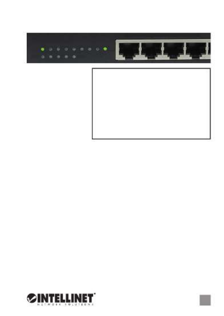
CONNECTIONS & INDICATORS
LEDs
The LED indicators — Power,
PoE, Link, Max — make it
easier to monitor the switch
and its connections. Note:
Only Ports 1-4 can provide
power to a connected device;
all powered devices should
also comply with IEEE 802.3af.
Ports
All ports on the switch support
Auto-MDI/MDI-X functionality,
so crossover cables and uplink ports are not needed for connections to PCs,
routers, hubs, other switches, etc. Cat5/5e/6 UTP/STP cables provide optimal
performance; if a status LED doesn’t indicate a link or activity, check the
corresponding device for proper setup and operation.
Power
Use the power cord to connect to an AC outlet and confirm that the power
LED is lit.
INSTALLATION
The switch includes brackets and screws for optional rack mounting:
1. Disconnect any cables from the switch.
2. Position a bracket over the mounting holes on one side of the switch and
secure it in place with screws (Page 11).
3. Repeat Step 2 on the other side of the switch.
4. Position the switch in the rack and screw the brackets to the rack.
5. Reconnect any cables.
Prior to use, it is recommended that the switch be placed/positioned on a level
surface with at least 25 mm (approx. 1”) of clearance for ventilation; away from
sources of electrical noise: radios, transmitters, broadband amplifiers, etc.; and
within 100 m (approx. 328’) of network devices it’s to be connected to.
For specifications, go to intellinetnetwork.com.
LED Status Operation
PWR On Power on
Off Check the AC connection; turn the power on
PoE On Port is linked to a PSE/PoE device
(Ports 1-4) Off No PSE/PoE device is linked
LNK On Valid port connection
Blinking Valid port connection; data transmitted/received
Off No link established
MAX On The combined power output of Ports 1-4 is at
the 70W maximum
Blinking The combined power output of Ports 1-4 has
exceeded the 70W maximum
Off The combined power output of Ports 1-4 is
below the 70W maximum
1 2 3 4
1 2 3 4 5 6 7 8
PoE MAX
PWR LNK
DEUTSCH 3
Fast Ethernet PoE+ Switch Deutsch
LED Status Operation
PWR An Gerät wird mit Strom versorgt
Aus Stromanschluss prüfen/Gerät einschalten
PoE An Port ist mit PSE/PoE-Gerät verbunden
(Ports 1-4) Aus Kein PSE/PoE-Gerät angeschlossen
LNK An Verbindung ist hergestellt
Blinkend Verbindung ist hergestellt; Datenübertragung
Aus Verbindung ist nicht hergestellt
MAX An Die kombinierte Ausgangsleistung der Ports 1-4 liegt
an der maximalen PoE-Kapazität von 70W
Blinkend Die kombinierte Ausgangsleistung der Ports 1-4 hat
die maximale PoE-Kapazität von 70W überschritten
Aus Die kombinierte Ausgangsleistung der Ports 1-4 liegt
unter der maximalen PoE-Kapazität von 70W
ANSCHLÜSSE & ANZEIGEN
LED-Anzeigen
Die LEDs — Strom, PoE,
Verbindung, Maximum —
vereinfachen das Ablesen
der Funktionen und
Anschlüsse. Hinweis:
Können nur die Ports 1-4
angeschlossene Geräte mit
Strom versorgen; diese
sollten mit IEEE 802.3af
kompatibel sein.
Ports
Alle Ports unterstützen Auto-MDI/MDI-X Funktionalität, daher werden Crosskabel
und Uplink-Ports für Verbindungen zu PCs, Routern, Hubs, anderen Switchen,
etc. nicht benötigt. Cat5/5e/6 UTP/STP-Kabel bieten die beste Performance.
Wenn eine LED keine Verbindung/Aktivität anzeigt, überprüfen Sie das
verbundene Gerät.
Strom
Schließen Sie das beiliegende Stromkabel an das Gerät (auf der Rückseite) und
an eine Steckdose an. Vergewissern Sie sich dass die “Power”-LED aufleuchtet.
INSTALLATION
Diesem Switch liegen Haltewinkel und Schrauben für optionale Rackmontage bei:
1. Trennen Sie alle Kabel von dem Switch.
2.
Platzieren Sie einen Haltewinkel über den Montagelöchern auf einer Seite des
Switches und fixieren Sie ihn mit Schrauben
(Seite 11)
.
3. Wiederholen Sie Schritt 2 auf der anderen Seite des Switches.
4. Platzieren Sie den Switch in dem Rack und schrauben Sie die Haltewinkel fest.
5. Schließen Sie alle Kabel wieder an.
Es wird empfohlen, den Switch vor der Nutzung folgendermaßen aufzustellen
auf ebenem Untergrund mit mind. 25 mm Rundumabstand für ausreichend
Luftdurchsatz; fern von anderen Übertragungsgeräten wie Radio, Breitband-
verstärker, etc.; und max. 100 m vom zu verbindenden Netzwerkgerät entfernt.
Die Spezifikationen finden Sie auf intellinetnetwork.com.
1 2 3 4
1 2 3 4 5 6 7 8
PoE MAX
PWR LNK
Produktspezifikationen
| Marke: | Intellinet |
| Kategorie: | Schalten |
| Modell: | 561686 |
| Breite: | 87 mm |
| Tiefe: | 153 mm |
| Gewicht: | 410 g |
| Produktfarbe: | Schwarz |
| Höhe: | 29 mm |
| Energiequelle: | AC/DC |
| AC Eingangsspannung: | 100 - 240 V |
| AC Eingangsfrequenz: | 50 - 60 Hz |
| DC input Spannung: | 44 - 57 V |
| Betriebstemperatur: | 0 - 40 °C |
| Relative Luftfeuchtigkeit in Betrieb: | 5 - 95 % |
| Netzstandard: | IEEE 802.3, IEEE 802.3af, IEEE 802.3at, IEEE 802.3u, IEEE 802.3x |
| Zertifizierung: | FCC Class B, CE, RoHS |
| Power over Ethernet (PoE): | Ja |
| Warentarifnummer (HS): | 85176990 |
| Betriebsanleitung: | Ja |
| Gehäusematerial: | Metall |
| LED-Anzeigen: | Activity, Link, PoE, Power, Speed |
| Temperaturbereich bei Lagerung: | -10 - 70 °C |
| Anzahl der basisschaltenden RJ-45 Ethernet Ports: | 6 |
| Basic Switching RJ-45 Ethernet Ports-Typ: | Fast Ethernet (10/100) |
| 10G-Unterstützung: | Nein |
| Kupfer Ethernet Verkabelungstechnologie: | 10BASE-T, 100BASE-TX |
| MAC-Adressentabelle: | 1000 Eintragungen |
| Routing-/Switching-Kapazität: | 1.2 Gbit/s |
| VLAN-Unterstützung: | Ja |
| Store-and-Forward: | Ja |
| unterstütze Kabeltypen: | Cat5e |
| Netzteil enthalten: | Ja |
| Gesamtleistung Power over Ethernet (PoE): | 65 W |
| Anzahl Power over Ethernet (PoE) Anschlüsse: | 4 |
| Anzahl der Uplink-Ports: | 2 |
Brauchst du Hilfe?
Wenn Sie Hilfe mit Intellinet 561686 benötigen, stellen Sie unten eine Frage und andere Benutzer werden Ihnen antworten
Bedienungsanleitung Schalten Intellinet

4 September 2024
4 September 2024
4 September 2024
4 September 2024
4 September 2024
4 September 2024
4 September 2024
4 September 2024
4 September 2024
4 September 2024
Bedienungsanleitung Schalten
- Schalten Asus
- Schalten Belkin
- Schalten Hama
- Schalten HP
- Schalten LogiLink
- Schalten Manhattan
- Schalten Nedis
- Schalten Philips
- Schalten SilverCrest
- Schalten Panasonic
- Schalten Brennenstuhl
- Schalten Clas Ohlson
- Schalten Cotech
- Schalten Profile
- Schalten ZyXEL
- Schalten Bosch
- Schalten Yamaha
- Schalten Powerfix
- Schalten CSL
- Schalten Eminent
- Schalten Linksys
- Schalten Netgear
- Schalten König
- Schalten PCE
- Schalten Renkforce
- Schalten Trotec
- Schalten Schneider
- Schalten Rex
- Schalten Kaiser
- Schalten Vivanco
- Schalten Abus
- Schalten Elro
- Schalten Smartwares
- Schalten Tesla
- Schalten Perel
- Schalten Nexa
- Schalten Tork
- Schalten GEV
- Schalten Goobay
- Schalten Lindy
- Schalten Tripp Lite
- Schalten Ansmann
- Schalten Mercusys
- Schalten Marmitek
- Schalten Honeywell
- Schalten TRENDnet
- Schalten TP-Link
- Schalten Kathrein
- Schalten Flamingo
- Schalten Alcatel
- Schalten Tiptel
- Schalten Black Box
- Schalten Alpine
- Schalten Techly
- Schalten Ebode
- Schalten Theben
- Schalten Vacmaster
- Schalten GAO
- Schalten Hager
- Schalten Behringer
- Schalten Omnitronic
- Schalten Monoprice
- Schalten Ecler
- Schalten Monacor
- Schalten Huawei
- Schalten JUNG
- Schalten Victron Energy
- Schalten Ei Electronics
- Schalten Edimax
- Schalten Totolink
- Schalten D-Link
- Schalten Sylvania
- Schalten Audiovox
- Schalten B-Tech
- Schalten QNAP
- Schalten SPC
- Schalten Speaka
- Schalten Digitus
- Schalten Sygonix
- Schalten DataVideo
- Schalten Lancom
- Schalten LevelOne
- Schalten Merten
- Schalten APC
- Schalten Eberle
- Schalten Cisco
- Schalten Delta Dore
- Schalten Grässlin
- Schalten Tenda
- Schalten CyberPower
- Schalten Boss
- Schalten IFM
- Schalten Intertechno
- Schalten Elation
- Schalten Ubiquiti Networks
- Schalten Kramer
- Schalten Aeon Labs
- Schalten Eaton
- Schalten AV:link
- Schalten Hikvision
- Schalten Vemer
- Schalten PreSonus
- Schalten Planet
- Schalten EnGenius
- Schalten Finder
- Schalten Mikrotik
- Schalten Shimano
- Schalten Homematic IP
- Schalten Berker
- Schalten Dormakaba
- Schalten Emerson
- Schalten Generac
- Schalten Intermatic
- Schalten KlikaanKlikuit
- Schalten Mercury
- Schalten Paladin
- Schalten Provision ISR
- Schalten Robbe
- Schalten SEC24
- Schalten Steren
- Schalten Suevia
- Schalten AMX
- Schalten Triax
- Schalten WHALE
- Schalten Vimar
- Schalten Cudy
- Schalten Siig
- Schalten Electro Harmonix
- Schalten RGBlink
- Schalten Iogear
- Schalten StarTech.com
- Schalten Smart-AVI
- Schalten Dahua Technology
- Schalten PAC
- Schalten Gefen
- Schalten Avocent
- Schalten Legrand
- Schalten Atlantis Land
- Schalten CYP
- Schalten H-Tronic
- Schalten ATen
- Schalten Axing
- Schalten KanexPro
- Schalten SmartAVI
- Schalten Advantech
- Schalten Kraus & Naimer
- Schalten Chacon
- Schalten Juniper
- Schalten Fibaro
- Schalten Phoenix Contact
- Schalten Audac
- Schalten OSD Audio
- Schalten Wentronic
- Schalten SunBriteTV
- Schalten BZBGear
- Schalten Crestron
- Schalten Kemo
- Schalten ORNO
- Schalten Extron
- Schalten Atlona
- Schalten Equip
- Schalten Heitronic
- Schalten Hamlet
- Schalten STI
- Schalten Matrox
- Schalten Blustream
- Schalten Vivolink
- Schalten Mach Power
- Schalten Ernitec
- Schalten Cambium Networks
- Schalten ConnectPro
- Schalten Micro Connect
- Schalten Intelix
- Schalten ICasa
- Schalten Maclean Energy
- Schalten Cooking Performance Group
- Schalten Flic
- Schalten Liberty
- Schalten Noark
- Schalten 2USB
- Schalten KVM-TEC
- Schalten Setti+
- Schalten PureLink
Neueste Bedienungsanleitung für -Kategorien-

15 Oktober 2024
12 Oktober 2024
11 Oktober 2024
8 Oktober 2024
8 Oktober 2024
5 Oktober 2024
4 Oktober 2024
4 Oktober 2024
4 Oktober 2024
3 Oktober 2024