Hikvision DS-K1T802M Bedienungsanleitung
Hikvision
Zugangskontrollsystem
DS-K1T802M
Lesen Sie kostenlos die 📖 deutsche Bedienungsanleitung für Hikvision DS-K1T802M (135 Seiten) in der Kategorie Zugangskontrollsystem. Dieser Bedienungsanleitung war für 36 Personen hilfreich und wurde von 2 Benutzern mit durchschnittlich 4.5 Sternen bewertet
Seite 1/135

UD.6L0206D1130A01
Access Control Terminal
User Manual

Access Control Terminal·
·
·
··User Manual
i
User Manual
© 2015 Hangzhou Hikvision Digital Technology Co., Ltd.
This manual is applied for access control terminal.
Product
Serials
Model
Product Name
DS-K1T802
DS-K1T802E
Access Control Terminal ( EM
Card)
DS-K1T802M
Access Control Terminal (Mifare
Card)
It includes instrucons on how to use the Product. The soware embodied in
the Product is governed by the user license agreement covering that Product.
About this Manual
This Manual is subject to domesc and internaonal copyright protecon.
Hangzhou Hikvision Digital Technology Co., Ltd. (“Hikvision”) reserves all rights
to this manual. This manual cannot be reproduced, changed, translated, or
distributed, parally or wholly, by any means, without the prior wrien
permission of Hikvision.
Trademarks
and other Hikvision marks are the property of Hikvision and
are registered trademarks or the subject of applicaons for the same by
Hikvision and/or its aliates. Other trademarks menoned in this manual are
the properes of their respecve owners. No right of license is given to use
such trademarks without express permission.
Disclaimer
TO THE MAXIMUM EXTENT PERMITTED BY APPLICABLE LAW, HIKVISION MAKES NO WARRANTIES,
EXPRESS OR IMPLIED, INCLUDING WITHOUT LIMITATION THE IMPLIED WARRANTIES OF
MERCHANTABILITY AND FITNESS FOR A PARTICULAR PURPOSE, REGARDING THIS MANUAL.
HIKVISION DOES NOT WARRANT, GUARANTEE, OR MAKE ANY REPRESENTATIONS REGARDING THE
USE OF THE MANUAL, OR THE CORRECTNESS, ACCURACY, OR RELIABILITY OF INFORMATION
CONTAINED HEREIN. YOUR USE OF THIS MANUAL AND ANY RELIANCE ON THIS MANUAL SHALL BE
WHOLLY AT YOUR OWN RISK AND RESPONSIBILITY.

Access Control Terminal·
·
·
··User Manual
ii
TO THE MAXIMUM EXTENT PERMITTED BY APPLICABLE LAW, IN NO EVENT WILL HIKVISION, ITS
DIRECTORS, OFFICERS, EMPLOYEES, OR AGENTS BE LIABLE TO YOU FOR ANY SPECIAL,
CONSEQUENTIAL, INCIDENTAL, OR INDIRECT DAMAGES, INCLUDING, AMONG OTHERS, DAMAGES
FOR LOSS OF BUSINESS PROFITS, BUSINESS INTERRUPTION, SECURITY BREACHES, OR LOSS OF DATA
OR DOCUMENTATION, IN CONNECTION WITH THE USE OF OR RELIANCE ON THIS MANUAL, EVEN IF
HIKVISION HAS BEEN ADVISED OF THE POSSIBILITY OF SUCH DAMAGES.
SOME JURISDICTIONS DO NOT ALLOW THE EXCLUSION OR LIMITATION OF LIABILITY OR CERTAIN
DAMAGES, SO SOME OR ALL OF THE ABOVE EXCLUSIONS OR LIMITATIONS MAY NOT APPLY TO YOU.
Support
Should you have any quesons, please do not hesitate to contact your local
dealer.
0100001051101

Access Control Terminal·
·
·
··User Manual
iii
Regulatory Informaon
FCC Informaon
FCC compliance: This equipment has been tested and found to comply with the
limits for a digital device, pursuant to part 15 of the FCC Rules. These limits are
designed to provide reasonable protecon against harmful interference when
the equipment is operated in a commercial environment. This equipment
generates, uses, and can radiate radio frequency energy and, if not installed
and used in accordance with the instrucon manual, may cause harmful
interference to radio communicaons. Operaon of this equipment in a
residenal area is likely to cause harmful interference in which case the user
will be required to correct the interference at his own expense.
FCC Condions
This device complies with part 15 of the FCC Rules. Operaon is subject to the
following two condions:
1. This device may not cause harmful interference.
2. This device must accept any interference received, including interference
that may cause undesired operaon.
EU Conformity Statement
This product and - if applicable - the supplied accessories too
are marked with "CE" and comply therefore with the applicable
harmonized European standards listed under the Low Voltage
Direcve 2006/95/EC, the EMC Direcve 2004/108/EC, the RoHS
Direcve 2011/65/EU.
2012/19/EU (WEEE direcve): Products marked with this
symbol cannot be disposed of as unsorted municipal waste in
the European Union. For proper recycling, return this product
to your local supplier upon the purchase of equivalent new
equipment, or dispose of it at designated collecon points. For
more informaon see: www.recyclethis.info.
2006/66/EC (baery direcve): This product contains a baery
that cannot be disposed of as unsorted municipal waste in the
European Union. See the product documentaon for specic
baery informaon. The baery is marked with this symbol,
which may include leering to indicate cadmium (Cd), lead (Pb),
or mercury (Hg). For proper recycling, return the baery to
your supplier or to a designated collecon point. For more informaon see:
www.recyclethis.info.

Access Control Terminal·
·
·
··User Manual
iv
Industry Canada ICES-003 Compliance
This device meets the CAN ICES-3 (A)/NMB-3(A) standards requirements.
Safety Instrucon
These instrucons are intended to ensure that user can use the product
correctly to avoid danger or property loss.
The precauon measure is divided into and : Warnings Cauons
Warnings: Neglecng any of the warnings may cause serious injury or death.
Cauons: Neglecng any of the cauons may cause injury or equipment
damage.
Warnings
All the electronic operaon should be strictly compliance with the electrical
safety regulaons, re prevenon regulaons and other related regulaons
in your local region.
Please use the power adapter, which is provided by normal company. The
power consumpon cannot be less than the required value.
Do not connect several devices to one power adapter as adapter overload
may cause over-heat or re hazard.
Please make sure that the power has been disconnected before you wire,
install or dismantle the device.
When the product is installed on wall or ceiling, the device shall be rmly
xed.
If smoke, odors or noise rise from the device, turn o the power at once and
unplug the power cable, and then please contact the service center.
If the product does not work properly, please contact your dealer or the
nearest service center. Never aempt to disassemble the device yourself.
(We shall not assume any responsibility for problems caused by unauthorized
repair or maintenance.)
Cauons
Do not drop the device or subject it to physical shock, and do not expose it
to high electromagnesm radiaon. Avoid the equipment installaon on
Warnings Follow
these safeguards
to prevent
serious injury or
death.
Cauons Follow these
precauons to
prevent potenal
injury or material
damage.

Access Control Terminal·
·
·
··User Manual
v
vibraons surface or places subject to shock (ignorance can cause equipment
damage).
Do not place the device in extremely hot efer to the specicaon of the (r
device for the detailed operang temperature), cold, dusty or damp locaons,
and do not expose it to high electromagnec radiaon.
The device cover for indoor use shall be kept from rain and moisture.
Exposing the equipment to direct sun light, low venlaon or heat source
such as heater or radiator is forbidden (ignorance can cause re danger).
Do not aim the device at the sun or extra bright places. A blooming or smear
may occur otherwise (which is not a malfuncon however), and aecng the
endurance of sensor at the same me.
Please use the provided glove when open up the device cover, avoid direct
contact with the device cover, because the acidic sweat of the ngers may
erode the surface coang of the device cover.
Please use a so and dry cloth when clean inside and outside surfaces of the
device cover, do not use alkaline detergents.
Please keep all wrappers aer unpack them for future use. In case of any
failure occurred, you need to return the device the factory with the to
original wrapper. Transportaon without the original wrapper may result in
damage on the device and lead to addional costs.
Improper use or replacement of the baery may result in hazard of explosion.
Replace with the same or equivalent type only. Dispose of used baeries
according to the instrucons provided by the baery manufacturer.

Access Control Terminal·
·
·
··User Manual
vi
Table of Contents
1 Overview ...................................................................................................... 1
1.1 Introducon ................................................................................................ 1
1.2 Main Features ............................................................................................. 1
2 Appearance .................................................................................................. 3
2.1 Appearance of the Termianl ....................................................................... 3
2.2 Descripon of Keypad Items 4......................................................................
3 Terminal Connecon .................................................................................... 5
3.1 Terminal Descripon 5..................................................................................
3.2 External Device Wiring ............................................................................... 6
4 Installaon ................................................................................................... 8
4.1 Mounng with Gang Box ............................................................................ 8
4.2 Mounng without Gang Box ...................................................................... 9
5 Acvang the Access Control Terminal ....................................................... 11
5.1 Acvang via SADP Soware ................................................................... 11
5.2 Acvang via Client Soware ................................................................... 13
6 Basic Operaon .......................................................................................... 17
6.1 User Management .................................................................................... 18
6.1.2 ding User Ad ........................................................................................ 18
6.1.2 Eding User ........................................................................................ 20
6.1.3 Searching User ................................................................................... 22
6.1.4 leng the User De ............................................................................... 23
6.2 Communicaon Sengs .......................................................................... 23
6.3 System Sengs ........................................................................................ 24
6.3.1 storing Sengs Re ............................................................................... 25
6.3.2 Seng login Password ....................................................................... 26
6.3.3 Door Sengs ...................................................................................... 26
6.3.4 Sengs Authencaon Mode ........................................................... 27
6.3.5 Reboong Device ............................................................................... 28
6.4 Time Sengs ............................................................................................ 28
6.5 Permission Sengs .................................................................................. 29
6.6 System Informaon .................................................................................. 32
7 Client Operaon ......................................................................................... 34
7.1 Overview of Access Control System ......................................................... 34
7.1.1 Descripon ......................................................................................... 34
7.1.2 Conguraon Flow ............................................................................. 34
7.2 Device Management ................................................................................ 36

Access Control Terminal·
·
·
··User Manual
vii
7.2.1 Controller Management ..................................................................... 36
7.2.2 Access Control Point Management .................................................... 45
7.3 Permission Management .......................................................................... 48
7.3.1 Person Management .......................................................................... 48
7.3.2 Card Management .............................................................................. 53
7.3.3 Schedule Template ............................................................................. 57
7.3.4 Door Status Management .................................................................. 62
7.3.5 Interact Conguraon ........................................................................ 66
7.3.6 Access Permission Conguraon ....................................................... 71
7.3.7 Attendance Management .................................................................. 77
7.3.8 Advanced Funcons ......................................................................... 104
7.4 Checking Status and Event ..................................................................... 113
7.4.1 Status Monitor ................................................................................. 113
7.4.2 Access Control Event ........................................................................ 115
7.4.3 Event Search ..................................................................................... 116
7.5 System Maintenance .............................................................................. 118
7.5.1 Log Management ............................................................................. 118
7.5.2 System Conguraon ....................................................................... 122

Access Control Terminal·
·
·
··User Manual
1
1 Overview
1.1 Introducon
Figure 1-1 DS-K1T802 Series Standalone Access Control Terminal
DS-K1T802 a series of standalone access control terminal designed is
with a LCD display screen. It supports TCP/IP network communicaon,
oine records storage funcons and so on.
1.2 Main Features
Equipped with 32-bit high-speed processor
Supports TCP/IP network communicaon, with self-adapve network
interface. The communicaon data is specially encrypted to relieve the
concern of privacy leak
Supports EM card and Mifare card reading
Supports authencaon methods of card, card and password
Doorbell ring design
Supports me synchronizaon via NTP, manual or automac method

Access Control Terminal·
·
·
··User Manual
2
Supports online upgrade, and remote operaon and device reboong
control
The access controller can store thousand legal cards and thousand 3 10
card swiping records
Unlocking overtime alarm, invalid card swiping over mes alarm, blacklist
alarm, and duress card/code alarm
Supports various card types as normal/ disabled/ blacklist/ patrol/ guest/
duress/ super card, etc.
Data can be permanently saved aer power-o
Accurate data and me display provided by built-in electronic clock and
watchdog program to ensure the basic funcon of the terminal
Remotely device reboong control
Supports alarm of oine event exceeding 90%

Access Control Terminal·
·
·
··User Manual
3
2 Appearance
2.1 Appearance of the Termianl
Please refer to the following content for detailed informaon of the
terminal .
Figure 2-1 Appearance of Access Control Terminal
Table 2-1 Descripon of Access Control Terminal
No.
Name
Descripon
1
LCD Display
Screen
First Line: display date
Second Line: display me
Third Line: display authencaon
informaon or swiping status
2
Power
Indicator
Slow Flicking
Green
Card reader is working
properly.
Solid Green
for a period
The operaon of
pressing keys or
swiping card is valid.

Access Control Terminal·
·
·
··User Manual
4
Solid Red for a
period
The operaon of
pressing keys or
swiping card is valid. in
No.
Name
Descripon
3
Link
Indicator
Solid light
Normal
O
Network Excepon
4
Keypad
Numeric key 0 to 9, Clearing key *, and
Conrming key #
5
Door Bell
Door Bell Ring
2.2 Descripon of Keypad Items
Table 2-2 Descripon of Keys
No.
Descripon
0 to 9
Numeric Keys: Enter number in the textbox.
2 and 8
Direcon Keys: Select icons in the menu.
*
Exing Key: Click the key to exit the menu.
#
Conrming Key: Click the key to conrm
operaons.

Access Control Terminal·
·
·
··User Manual
5
3 Terminal Connecon
3.1 Terminal Descripon
The following table shows the terminals descripon
Table 3-1 Terminal Descripon
Descripon
Color
Power Input
12V DC
Red
GND
Black
Bell
Bell+
Orange
Bell-
Yellow
Door Lock
BUTTON_IN
Purple
DOOR_COM
Green
DOOR_NO/NC
Blue
SENSOR_IN
White
GND
Black
12V_LOCK
Brown

Access Control Terminal·
·
·
··User Manual
6
3.2 External Device Wiring
Power Supply Wiring
Doorbell Wiring
Figure 3-1 Power Supply Connecon
Diagram
Figure 3-2 Doorbell Wiring Diagram
Door Buon Wiring
Door Lock Wiring
Figure 3-3 Door Buon Wiring Diagram
Figure 3-4 Door Lock Wiring
Diagram

Access Control Terminal·
·
·
··User Manual
7
Door Magnec Wiring
Figure 3-5 Door Magnec Wiring Diagram

Access Control Terminal·
·
·
··User Manual
8
4 Installation
Before you start
Please make sure that the device in the package is in good condion
and all the assembly parts are included.
Make sure that all the related equipment is power-o during the
installaon.
Check the specicaon of the products for the installaon
environment.
Check whether the power supply is matched with your AC outlet to
avoid damage.
If the product does not funcon properly, please contact your dealer
or the nearest service center. not disassemble the camera for Do
repair or maintenance by yourself.
Please make sure the wall is strong enough to withstand three mes
the weight of the device and the mounng.
4.1 Mounng with Gang Box
Steps:
1. Route the cables through the cable hole of the mounng base.
2. Align the screw holes on mounng base with the screw holes on
gang box.
3. Fix the mounng base on the gang box with inserng two
KA4*22-SUS screws (supplied) into the two screw holes.
Figure 4-1 Install the Mounng
Figure 4-2 Attach the Front Cover

Access Control Terminal·
·
·
··User Manual
9
Base
4. Connect the corresponded cables.
5. Align the buckle of the front cover with the slot of the mounng
base, and hang the front cover onto the mounng base. Make sure
the buckle is embedded in the slot. to
6. Secure the front cover with inserng and ghtening two screws on
the boo of device. m
Figure 4-3 Secure the Front Cover
4.2 Mounng without Gang Box
Steps:
1. Drill 4 screw holes in the wall according to the holes of the mounting
base, and then insert expansion screws sockets (not supplied) into
the holes.
2. Route the cables through the cable hole of the mounng base.
3. Align the screw holes on the base with the screw sockets on the wall.
4. Attach the mounng base on the wall with Inserng 4 KA4*22-SUS
screws (supplied) into the 4 screw sockets.

Access Control Terminal·
·
·
··User Manual
10
Figure 4-4 Install the Mounng
Base
Figure 4-5 Attach the Front Cover
5. Connect the corresponded cables.
6. Align the buckle of the front cover with the slot of the mounng
base, and hang the front cover onto the mounng base. Make sure
the buckle is embedded in the slot. to
7. Secure the front cover with inserng and tightening two screws on
the boo of device.m
Figure 4-6 Secure the Front Cover

Access Control Terminal·
·
·
··User Manual
11
5 Acvang the Access Control
Terminal
Purpose:
You are required to acvate the terminal rst before using it.
Acvaon via SADP, and Acvaon via client soware are supported.
The default values of the control terminal are as follows.
The default IP address: 192.0.0.64.
The default port No.: 8000.
The default user name: admin.
5.1 Acva via SADP Soware ng
SADP soware is used for detecng the online device, acvang the
device, and resetng the password.
Get the SADP soware from the supplied disk or the ocial website,
and install the SADP according to the prompts. Follow the steps to
acvate the control panel.
Steps:
1. Run the SADP soware to search the online devices.
2. Check the device status from the device list, and select an inacve
device.

Access Control Terminal·
·
·
··User Manual
12
Figure 5-1 SADP Interface
3. Create a password and input the password in the password eld, and
conrm the password.
STRONG PASSWORD RECOMMENDED– We highly
recommend you create a strong password of your own
choosing (using a minimum of 8 characters, including
upper case leers, lower case leers, numbers, and
special characters) in order to increase the security of
your product. And we recommend you reset your
password regularly, especially in the high security system,
reseng the password monthly or weekly can beer
protect your product.
4. Click to save the password. OK
You can check whether the acvaon is completed on the pop-up
window.
If acvaon failed, please make sure that the password meets the
requirement and then try again.
5. Change the device IP address to the same subnet with your
computer by modifying the IP address manually.

Access Control Terminal·
·
·
··User Manual
13
Figure 5-2 Modify Network Parameters Interface
6. Input the password and click the buon to acvate your IP Save
address modicaon.
5.2 Acva via Client Soware ng
The client soware is versale video management soware for
mulple kinds of devices.
Get the client soware from the supplied disk or the ocial website,
and install the soware according to the prompts. Follow the steps to
acvate the control panel.
Steps:
1. Run the client soware and the control panel of the soware pops up, as
shown in the gure below.
2. Click the icon on the upper-le side of the page, select Access
Control to enter the control panel.

Access Control Terminal·
·
·
··User Manual
14
Figure 5-3 Control Panel Interface
3. Click the Controller Management icon to enter the Controller
Management interface, as shown in the gure below.
Figure 5-4 Device List
4. Check the device status from the device list, and select an inacve

Access Control Terminal·
·
·
··User Manual
15
device.
5. Click the Acvate buon to pop up the Acvaon interface.
Figure 5-5 List Selecng Interface
6. Create a password and input the password in the password eld, and
conrm the password.

Access Control Terminal·
·
·
··User Manual
16
STRONG PASSWORD RECOMMENDED– We highly recommend
you create a strong password of your own choosing (using a
minimum of 8 characters, including upper case leers, lower case
leers, numbers, and special characters) in order to increase the
security of your product. And we recommend you reset your
password regularly, especially in the high security system,
reseng the password monthly or weekly can beer protect your
product.
7. Click button to start acvaon. OK
8. Click the buon to pop up the Network Parameter
Modicaon interface.
9. Change the device IP address to the same subnet with your computer by
modifying the IP address manually.
10. Input the password to acvate your IP address modicaon.

Access Control Terminal·
·
·
··User Manual
17
6 Basic Operaon
Before You Start:
You should acvate the device before the rst login. Otherwise, aer
powered on, the system will switch into acva on nofying interface. For ti
detailed informaon about acvaon, see Chapter 5.
You should enter the default password for the rst login.
Enter to reset the login password. Sys Opt-Login Pwd
The default password is 12345.
Steps:
1. The device enters the inial interface automacally aer powered on.
Figure 6-1 Inial Interface
2. Enter [*] + [0] + [#] to enter the login interface
Figure 6-2 Login Interface
3. Enter the login password.
Click the key to conrm the sengs I the conguraon password #. f
authencaon failed, the system will return to the inial interface, and if
the conguraon password is successfully authencat , the system will ed
enter the menu operaon interface
Access Control Terminal·
·
·
··User Manual
18
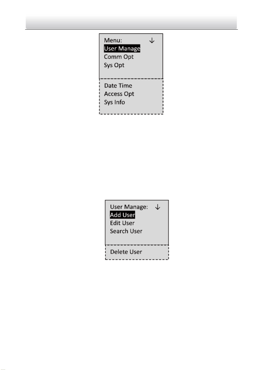
Figure 6-3 Menu Operaon Interface
On the menu operaon interface, you can manage users, set communicaon
parameters, set system parameters, and so on.
6.1 User Management
Purpose:
On the user management interface, you can add and manage users.
Steps:
1. Move the cursor to User Manage (user management) with the direcon keys.
2. Click the key to enter the adding user interface. #
Figure 6-4 User Management Interface
6.1.2 Adding User
Purpose:
In the menu, you can add users, and register card for the Add User
corresponding person.
Steps:
1. Move the cursor to (add user) by using the direcon keys. A Userdd
2. Click the key to enter the card registraon interface. #

Access Control Terminal·
·
·
··User Manual
20
The valid length of the password is 1 to 8 characters.
7. If the password registraon is not required, click the # key to return to the Add
User interface.
6.1.2 Eding User
Steps:
1. Move the cursor to by using direcon keys the user Edit User on
management interface.
2. Click the key to enter the managing user interface. #
Figure 6-8 User Eding Interface
3. Swipe the card or enter the card No. .
4. Click the key to enter the password setngs interface. #
1) Move the cursor to to enter the password changing Change PWD
interface.
2) Enter a new password.
3) Conrm the new password.
4) Click the key to conrm the sengs. #
Figure 6-9 Password Changing Interface
5. If the password is not required, click the # key to clear the congured
password.
6. Change the valid date
You can set the valid date (start/end date) of the card .

Access Control Terminal·
·
·
··User Manual
21
Figure 6-10 Validity Seng Interface
Click the key to conrm the setngs. #
7. Enable the rst card permission of the user.
1) Click the key to enter the eding mode. #
2) Press the direcon key to select whether to enable the rst card for
the user.
3) Click the key to conrm the eding. #
Figure 6-11 First Card Permission Setng Interface
Aer enabling rst card, the door remains open during the
pre-dened valid duraon.
8. Select the template for the user.
1) Click the key to enter the eding mode. #
2) Press the direcon key to select the template No..
Max.65 templates are selectable (including 64 schedule templates and
1 template disabling opon),the schedule template value is from to 01
64, and indicates the template 01. The template disabling Default
opon value is . 00
3) Click the key to conrm the edi . #ng

Access Control Terminal·
·
·
··User Manual
22
Figure 6-12 Template Sengs Interface
6.1.3 Searching User
Steps:
1. Move the cursor to Search User.
2. Click the key to enter the searching interface. #
Figure 6-13 Searching User Interface
3. Select and the list of all user will be displayed. All User
Figure 6-14 Searching for All User Interface
4. Select the enter the query specied user interface. Selected User to
5. Swipe card or enter the card No..
Figure 6-15 Searching for Selected User Interface

Access Control Terminal·
·
·
··User Manual
23
6. Click the key to view the basic informaon about the card holder. #
Figure 6-16 User Informaon Interface
6.1.4 Deleting the User
Steps:
1. Move the cursor to Delete User #, and click the key to enter the deleng
interface.
Figure 6-17 User Deleng Interface
2. Swipe card or enter the card No..
3. Click the key to enter the conrmaon page. #
4. Select whether to conrm the setngs
You can click * key to return to the main menu.
6.2 Communication Settings
Purpose:
On the communicaon sengs interface, you can set network parameters ,
Steps:
Access Control Terminal·
·
·
··User Manual
25
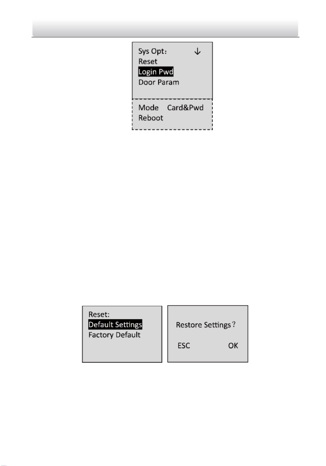
Figure 6-20 System Settings Interface
Reset: The device can be restored into factory defaults or default settings.
Login Pwd (Login Password): Change the login password.
Door Param (Door Parameters): Set parameters of the access control terminal,
including Open Time (Door Action Time), Open Time-out(Delayed Door Alarm),
Door Magnetic (Door Magnetic Status Settings), Button Type (Exit Button Status
Settings), and First Card settings.
Mode (Authentication Mode): You can select the card authentication mode.
Reboot (Reboot Device): You can reboot the device
6.3.1 Restoring Settings
Purpose:
On the restore settings interface, you can restore Factory Defaults or Default
Settings .
Steps:
1. Move the cursor to (restore settings by using direction keys the Reset ) on
system settings interface.
2. Click the key to enter the restore settings interface. #
Figure 6-21 Restore Settings Interface
3. Select Factory Defaults Default Settings to or .
Factory Defaults: After restoring factory defaults, all parameters of the
device are returned to the factory defaults.
Access Control Terminal·
·
·
··User Manual
26
Default Settings: After restoring defaults settings, parameters, excluding
network parameters and event parameters, are returned to the factory
defaults.
4. Click the key to implement the settings. #
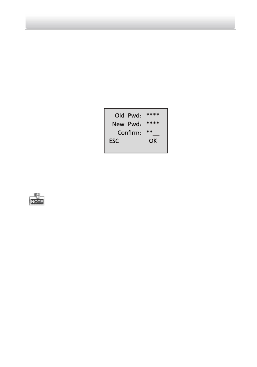
6.3.2 Setting login Password
Steps:
1. Click the key to enter the password settings interface. #
Figure 6-22 Password Changing Interface
1) Enter the old password.
2) Enter a new password.
3) Confirm the new password.
The valid password length should be 5 characters.
2. Click the key to confirm the settings. #
6.3.3 Door Settings
Purpose:
On the door settings interface, you can set door parameters, including Open
Time (Door Action Time), Open Time-out (Delayed Door Alarm), Door Magnetic
(Door Magnetic Status Settings), Button Type (Exit Button Status Settings), and
First Card settings.
Steps:
1. Move the cursor to Door Param (door settings by using direction keys in )
the system settings interface.
2. Click the key to enter the door settings interface. #

Access Control Terminal·
·
·
··User Manual
27
Figure 6-23 Door Settings Interface
3. Edit door parameters.
Open Time: Door action time, set the door action time: 1 ~ 255 s.
Open Time-out : Delayed door alarm, set the delayed door alarm threshold:
0 ~ 255s.
Door Magnetic: Door magnetic status settings Remain open and remain ,
closed are selectable.
Button Type: Exit button status settings, Remain open and remain closed
are selectable.
First Card: Set whether to enable the first card function, which is keeping
the door open with the first card .
4. Click the key to confirm the settings # .
6.3.4 Settings Authentication Mode
In this section, you can set the controller authentication mode for opening the
door, that is, , and Card Only Card & Password.
Steps:
1. Move the cursor to (Authentication Settings by using direction keys Mode )
in the system settings interface.
Figure 6-24 Authentication Settings Interface
2. Click the key to select the authentication mode. #

Access Control Terminal·
·
·
··User Manual
28
6.3.5 Rebooting Device
Steps:
1. Move the cursor to by using direction keys Reboot
2. Click the key to start the rebooting operation of the device. #
6.4 Time Settings
Steps:
1. Move the cursor to Date Time (time settings by using direction keys. )
2. Click the key to enter the time settings interface. #
Figure 6-25 Time Settings Interface
3. Select to edit the Edit or Date Time DST (Daylight Saving Time) parameters
of the device .
Edit Date Time:
Figure 6-26 Date Time Settings Interface
Edit DST (Daylight Saving Time)
Figure 6-27 DST Settings Interface

Access Control Terminal·
·
·
··User Manual
29
When enabling DST, you should set the offset time, the start time, and the
end time of DST.
Press * key to cancel the date/time settings, and return to the Date
Time interface.
Press # key to confirm the date/time settings, and return to the Date
Time interface.
6.5 Permission Settings
Purpose:
On the permission settings section, you can set the weekly schedule, holiday
schedule, Holiday group and template.
Steps:
1. Move the cursor (Access Operation by using direction keys. to Access Opt )
2. Click the key to enter the interface. #
Figure 6-28 Permission Settings Interface
Weekly Schedule Settings
Steps:
1. Move the cursor to by using direction keys. Weekly Plan
2. Click the key to enter the weekly schedule configuration interface. #

Access Control Terminal·
·
·
··User Manual
30
Figure 6-29 Weekly Schedule Settings Interface
3. Set the plan No., with entering the plan No. by the numeric keys.
Max. 32 plans can be configured, and the plan No. range is from 1 to 32.
4. Set the detailed time periods from Sunday to Saturday with entering the
start time and end time by the numeric keys.
5. Click the key to return to the interface * Access Opt .
Holiday Schedule Settings
Steps:
1. Move the cursor to Holiday Plan by using direction keys.
2. Click the key to enter the holiday schedule configuration interface. #
Figure 6-30 Holiday Schedule Settings Interface
3. Set the plan No., with entering the plan No. by the numeric keys.
Max. 128 plans can be configured, and the plan No. range is from 1 8. to 12
4. Set the detailed holiday information.
Date: Enter the start date and end date by the numeric keys.

Access Control Terminal·
·
·
··User Manual
31
Period: Enter the start time and end time by the numeric keys.
5. Click the key to return to the interface* Access Opt .
Holiday Group Settings
Steps:
1. Move the cursor to Holiday Group by using direction keys.
2. Click the key to enter the holiday group configuration interface. #
Figure 6-31 Holiday Group Settings Interface
3. Set the group No., with entering the group No. by the numeric keys.
Max. 64 groups can be configured, and the group No. range is from 1 . to 64
4. Set the holiday group. Move the cursor to holiday No.(the default is 000),
and
Enter the holiday No. configured in Holiday Schedule Settings by the
numeric keys.
The holiday schedule No. is separated by a comma .
5. Click the key to return to the interface* Access Opt .
Template Settings
Steps:
1. Move the cursor to Template by using direction keys.
2. Click the key to enter the template configuration interface. #
Figure 6-32 Template Settings Interface

Access Control Terminal·
·
·
··User Manual
32
3. Set the template No., with entering the template No. by the numeric keys.
Max. 64 templates can be configured, and the template No. range is from 1
to 64.
4. Enter the Weekly Plan No. by the numeric keys.
5. Set the Holiday groups. Move the cursor to holiday group No.(the default is
000), and Enter the holiday group No. configured in Holiday Group
Settings by the numeric keys.
The holiday group No. is separated by a comma.
6. Click the key to return to the interface* Access Opt .
6.6 System Information
Steps:
1. Move the cursor to Sys Info (system information by using direction keys. )
2. Click the key to enter the system information interface. #
Figure 6-33 System Information Interface
3. Select or Device . User Count Information
User Capacity
Figure 6-34 User Count Interface
Registered Amount: the count of user that is registered
Remainder Amount: the count of remainder registration amount
Total Amount: It refers to the maximum amount of cards
Access Control Terminal·
·
·
··User Manual
33
The default maximum card amount is 2000.
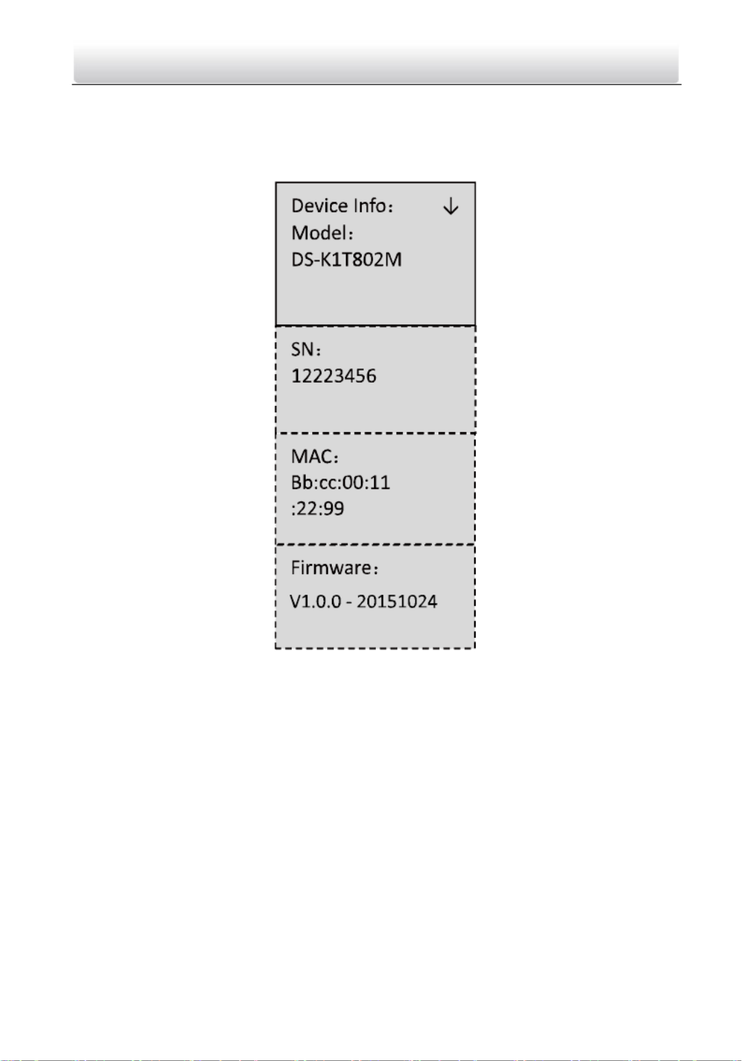
Device Information
In the device information interface, you can view the device name, the
serial No., Mac address, and so on.
Figure 6-35 Device Information Interface

Access Control Terminal·
·
·
··User Manual
34
7 Client Operation
7.1 Overview of Access Control System
7.1.1 Description
The access control system is a system of configuring permission of door access.
It provides multiple functionalities, including access controller management,
people/card management, permission configuration, door status management,
event search, etc.
This user manual describes the function, configuration and operation steps of
Access Control System. To ensure the properness of usage and stability of the
system, please refer to the contents below and read the manual carefully
before installation and operation.
7.1.2 Configuration Flow
Refer to the following flow chart for the configuration order.

Access Control Terminal·
·
·
··User Manual
35
Configure the Card Dispenser
Configure the Access Controller
Configure the Door
Configure the Department, Person and Card
Configure the Schedule Template (Week Plan,
Holiday Group and Schedule)
Configure and Download the Permission
View Status
Access Control Terminal·
·
·
··User Manual
36
7.2 Device Management
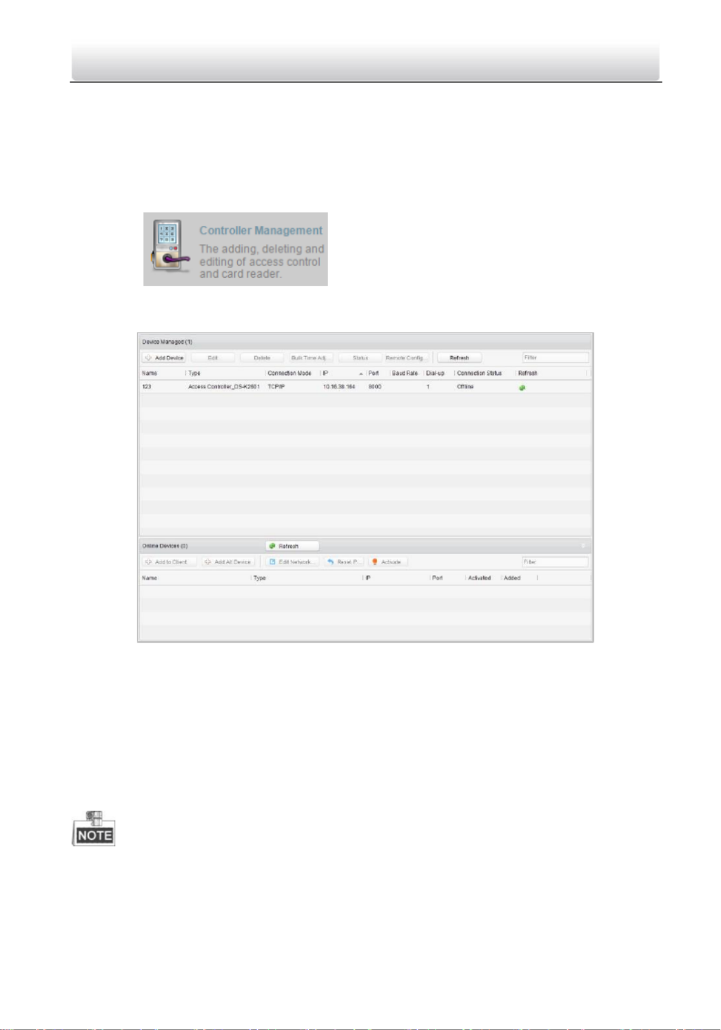
7.2.1 Controller Management
Interface Introduction
Click the icon to enter the controller management
interface.
The interface is divided into 2 parts: device management and online device
detection.
Device Management:
Manage the access control devices, including adding, editing, deleting, and
batch time synchronizing functions.
Online Device Detection:
Automatically detect online devices in the same subnet with the access control
server, and the detected devices can be added to the server in an easy way.
The control client can manage 100 access controllers at most.

Access Control Terminal·
·
·
··User Manual
37
Device Management
Adding Controller
Steps:
1. Click the to enter the a access controller interface. dd
2. Input the device name.
3. Select the access controller type in the dropdown list.
4. Select the connection mode in the dropdown list: TCP/IP, or COM port, or
Ehome.
TCP/IP: Connect the device via the network.
Ehome: Connect the device via the Ehome protocol.
5. Set the parameters of connecting the device.
If you choose to connect the device via network, you should input the IP
address and port No. of the device, and set the Dial-up value to 1.
If you choose to connect the device via Ehome protocol, you should input
an account.
For the detailed information about the account, refer to 15.1.3.
6. Click the button to finish adding.

Access Control Terminal·
·
·
··User Manual
38
You can click to check the detailed status of the controller, and click Status
Remote Configuration to configure the settings of the controller.
Editing Device (Basic Information)
Purpose:
After adding the device, some advanced parameters can be configured in the
editing device interface, e.g. downloading hardware parameters, reading
hardware parameters, time synchronizing, configuring access point, etc.
Steps:
1. In the device list, click button to edit the information of the selected Edit
added device.
2. Edit the basic parameters of the device on your demand, which are the
same as the ones when adding the device.
3. (Optional) Check the checkbox of to enable the holiday Enable Holiday
parameters when downloading permissions.
4. Click the button to finish editing. Edit
5. Click the Hardware Parameters Downloading button to download the
updated parameters to the local memory of the device.

Access Control Terminal·
·
·
··User Manual
39
Editing Device (Door Information)
Steps:
1. In the editing interface, click the button to edit the information of Door_1
the selected door.
1) Door Magnetic Remain Closed: The Door Magnetic is in the status of
(excluding special conditions).
2) Exit Button Type: The Exit Button Type is in the status of Remain
Open (excluding special conditions).
3) Door Locked Time(s): After swiping the normal card and relay action,
the timer for locking the door starts working.
4) Door Open for Disabled Person: The door magnetic can be enabled
with appropriate delay after disabled person swipes the card.
5) Door Open Timeout(s): The alarm can be triggered if the door has
not been close
6) Enable Lock Door when Door Close: This function has not been
supported yet.
7) Duress Code: The door can open by inputting the duress code when
there is a duress. At the same time, the access system can report the
duress event.
8) Super Password: The specific person can open the door by inputting
the super password.
2. Click the Restore Default Value to restore all parameters into default

Access Control Terminal·
·
·
··User Manual
40
settings.
3. Click the button to save parameters. Edit
4. Click the Hardware Parameters Downloading button to download the
updated parameters to the local memory of the device.
Editing Device (Card Reader Information)
Steps:
1. In the device list, select a card reader name to enter into the card reader
information editing interface.
2. Click the button to edit the basic information about the Basic Information
card reader.
3. Click the button to edit the expansion information Expansion Information
about the card reader.
4. Click the button to save parameters. Edit
5. Click the Hardware Parameters Downloading button to download the
updated parameters to the local memory of the device.
Deleting Device
Steps:
1. In the device list, select a device by clicking it, or select multiple devices by
pressing Ctrl button on your keyboard and clicking them one by one.

Access Control Terminal·
·
·
··User Manual
41
2. Click the button to delete the selected device(s).
3. Click button in the popup confirmation dialog to finish deleting. OK
Bulk Time Synchronization
Steps:
1. In the device list, select a device by clicking it, or select multiple devices by
pressing Ctrl button on your keyboard and clicking them one by one.
2. Click the button to start time synchronization. Bulk Time Adjustment
A message box will pop up on the lower-right corner of the screen when
the time synchronization is compelete d.
Status
In the device list, you can click button to enter view the status. Status
1) Door Status: The status of the connected door.
2) Host Status: The status of the host, including Storage Battery Power
Voltage, Device Power Supply Status, and Host Anti-Tamper Status.
3) Card Reader Status: The status of card reader.
4) Alarm Input Status: The alarm input status of each port.
5) Alarm Output Status: The alarm output status of each port.
6) Event Sensor Status: The event status of each port.
Remote Configuration
In the device list, you can click Remote Configuration button to enter the
remote configuration interface. On this this interface, you can set the access
parameters, enable the face detection function, and so on.

Access Control Terminal·
·
·
··User Manual
42
Network Settings
Purpose:
In the network settings interface, the network settings of the device can be
uploaded and reported.
Uploading Mode Settings

Access Control Terminal·
·
·
··User Manual
43
Steps:
1. In the access controller editing interface, click button to Network Settings
enter the network settings interface.
2. Click the Uploading Mode Settings button.
3. Select the center group in the dropdown list.
4. Tick the to enable the selected center group. Enable
5. Select the report type in the dropdown list.
6. Select the uploading mode in the dropdown list. You can enable N1/G1 for
the main channel and the backup channel, or select off to disable the main
channel or the backup channel.
The main channel and the backup channel cannot enable N1 or G1 at the same
time.
7. Click the button to save parameters. OK
Access Control Terminal·
·
·
··User Manual
44
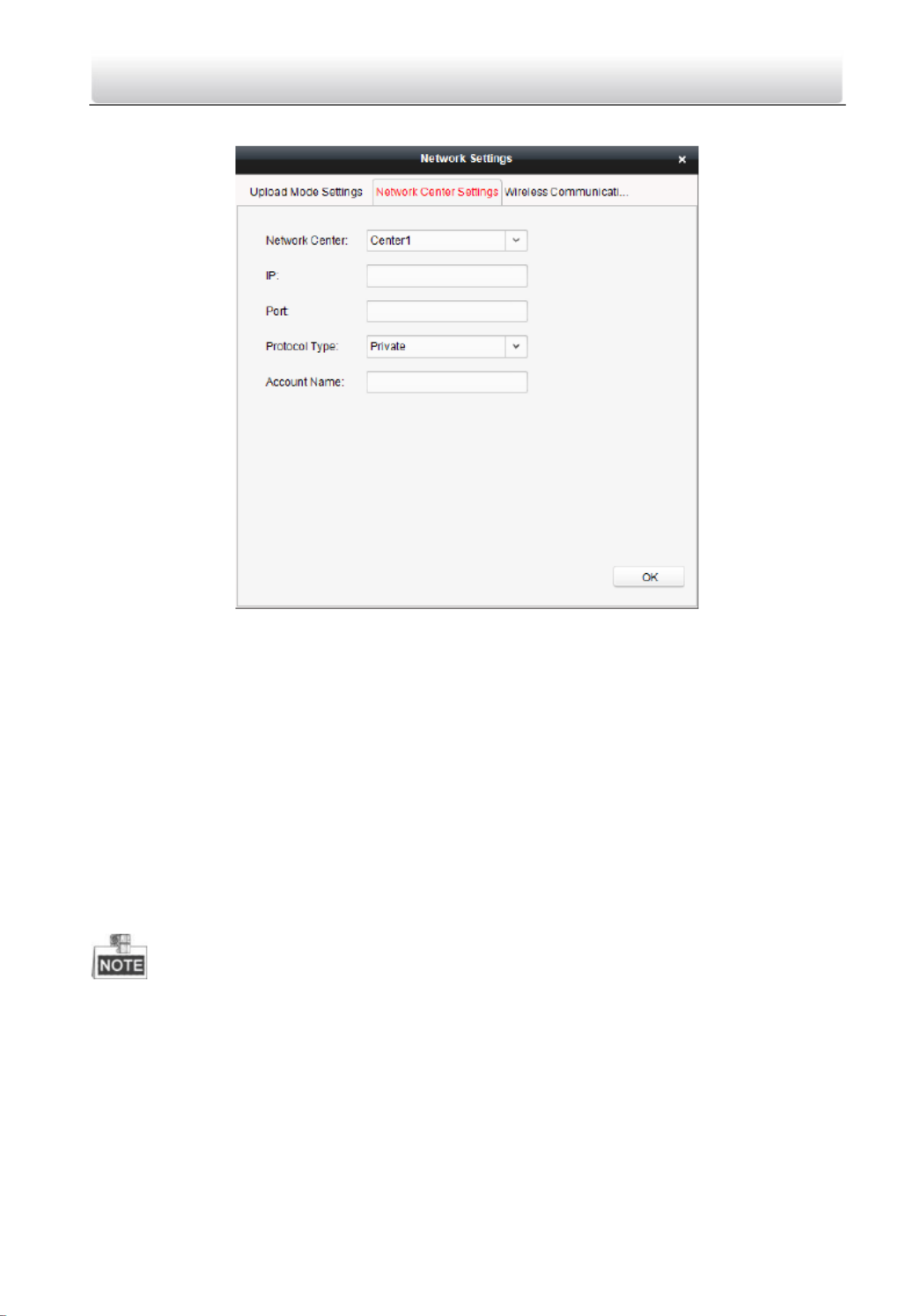
Network Center Settings
Steps:
1. In the access controller editing interface, click button to Network Settings
enter the network settings interface.
2. Click the button. Network Center Settings
3. Select the network center in the dropdown list.
4. Input IP address.
5. Input port number.
6. Select the protocol type.
7. Set an account name for the network center. A consistent account should
be used in one platform.
8. Click the button to save parameters. OK
• In the Ehome protocol, the default port number is 7661, and the port type
should be UDP port. Related settings files need modifying if the port type
does not match.
• The port number of the wireless network and wired network should be
consistent with the port number of Ehome.

Access Control Terminal·
·
·
··User Manual
45
7.2.2 Access Control Point Management
Interface Introduction
Click the icon on the control panel to enter the
door management interface.
Group Management
The doors can be added to different groups to realize the centralized
management.
Door Management
Manage the specific door under the door group, including importing, editing
and deleting door.
Group Management
Adding Group
Steps:
1. Click the button to pop up the Add Group dialog.

Access Control Terminal·
·
·
··User Manual
46
2. Input the group name in the text field and click the button to
finish adding.
Multi-level groups are not supported yet.
Editing Group
Steps:
Double-click the group or right-click the group and select Edit in the right-click
menu.
Deleting Group
To delete a group, three ways are supported.
Click to select a group and click the button.
Right-click a group and select Delete in the popup menu.
Move the mouse onto the group and click icon of it.
And then click the OK button in the popup window.
Access Control Point Management
Access control points under the group can also be edited, refer to the following
instructions.
Importing Access Control Point
Steps:
1. Click the button to pop up the access control point
importing interface.
2. Select a access control point to import by clicking it.
3. Click to select a group in the right side bar to import to.

Access Control Terminal·
·
·
··User Manual
47
4. Click button to import the selected access control
points or click to import all the available access control
points.
• You can click button on the upper-right corner of the window to
create a new group.
• The control client can manage 100 access control points at most.
Editing Access Control Point
Steps:
1. Click to select an access control point in the list and click the
button to edit the access control point.
2. Edit the Door Name and Position.
3. Click button to finish editing.
You can also enter the Edit interface by double clicking the door from the list.
Deleting Access Control Point
Several ways are supported to delete the access control point, as shown below.
Click to select a group in the group list, select door(s) under it, and click
button.
Click to select a group in the group list, and click button
to delete all access control points under the group.
Move the mouse onto a group in the group list, and click button to
delete all access control points under the group.
Uou can also edit/delete a door on the Import Access Control Point panel.

Access Control Terminal·
·
·
··User Manual
48
Steps:
1. Select a control point on the panel. Group
2. Click the / icon to enter the panel or to Edit Access Control Point
delete the control point.
7.3 Permission Management
7.3.1 Person Management
Interface Introduction
Click the icon on the control panel of the software.
Adding, editing, deleting and filtering of the department and person are
supported in this interface.

Access Control Terminal·
·
·
··User Manual
49
Department Management
Steps:
1. In the department list, click button to pop up the adding
department interface.
Multi-level department system can be created. Click a department as
the upper-level deparment and click button, and
then the added department will be the sub-department of it.

Access Control Terminal·
·
·
··User Manual
50
Up to 10 levels can be created.
2. You can double-click an added department to edit its name.
3. You can click to select a department, and click the
button to delete it.
The lower-level departments will be deleted as well if you delete a
department.
Make sure there is no person added under the department, or the
department cannot be deleted.
Person Management
In the person management interface, double-click the person name or
click the Edit button to edit the person informationt
In the person management interface, click the Delete button to delete
the person.
Up to 2000 persons ban be added.
Inputting General Information
Steps:
1. Select a department in the list and click the in the person
information list to pop up the adding person interface.

Access Control Terminal·
·
·
··User Manual
52
Inputting Fingerprint
Steps:
1. In the personal information interface, click the button. Fingerprint
2. Click the Start Register button, and select the fingerprint to be input.
3. Click the button to save the parameter. Save
Click the button to delete the fingerprint. Delete Fingerprint
Click the Delete All button to clear all fingerprints input.
Models DS-K1T802M and DS-K1T802E do not support fingerprint
function .

Access Control Terminal·
·
·
··User Manual
53
7.3.2 Card Management
Interface Introduction
Click on the control panel of the software to enter
the card management interface.
The cards are divided into 3 types: Blank Card, Normal Card, and Lost Card.
Blank Card: A card has not been issued with a person.
Normal Card: A card is issued with a person and is under normal using.
Lost Card: A card is issued with a person and is reported as lost.
Blank Card
Adding Card
Before you start:
Make sure a card dispenser is connected to the PC and is configured already.
Refer to Section for details. 0 Card Dispenser Configuration
Steps:
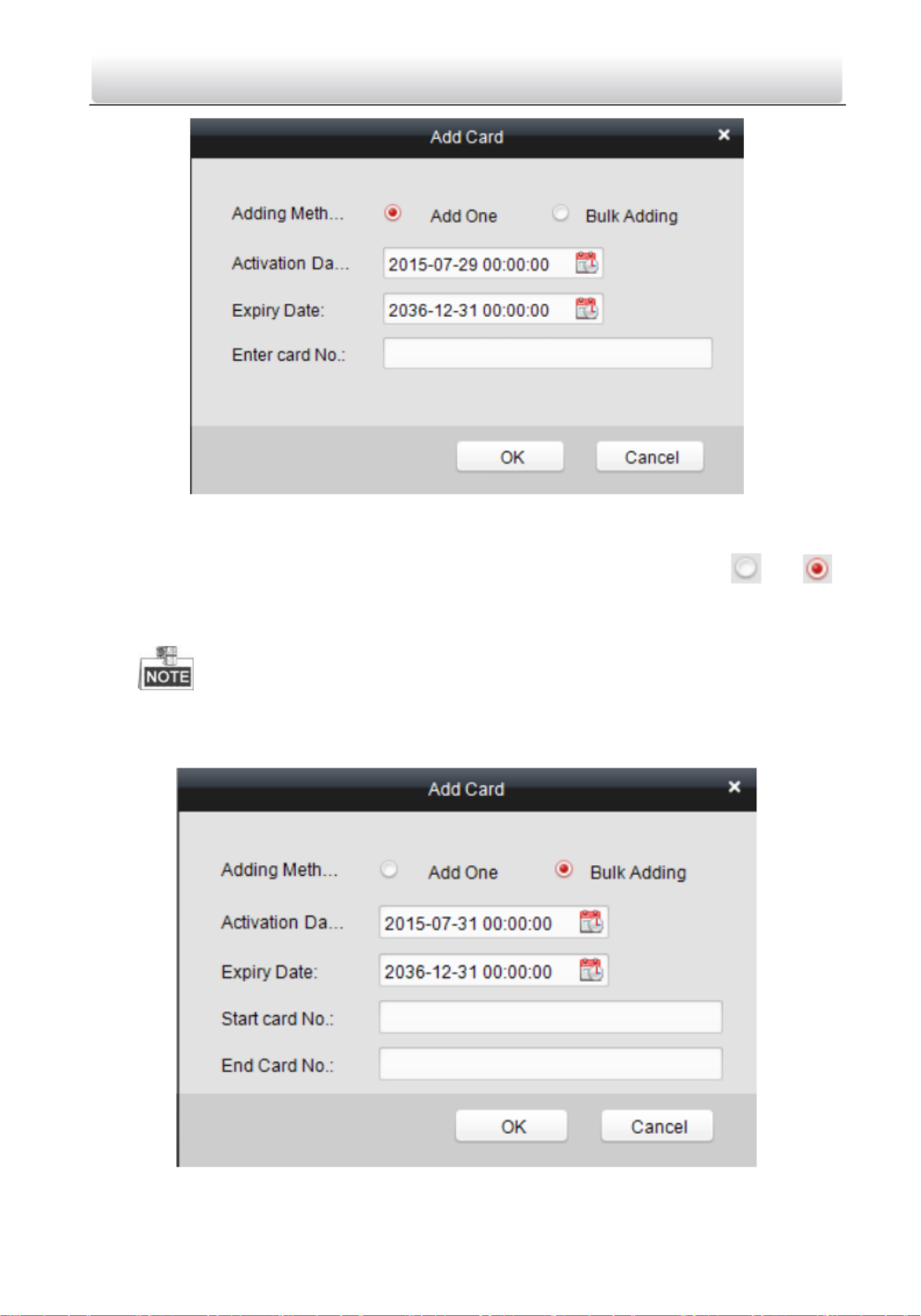
1. Click the tton to add cards. bu
2. Two modes of adding cards are supported.
Adding Single Card
Choose the Single Add as the adding mode by clicking the to and
input the Start Date, Expiring Date and Card No. in the text field.
Access Control Terminal·
·
·
··User Manual
54
Batch Adding Cards
Choose the as the adding mode by clicking the to Bulking Adding
and input the activation date, expiry date, start card No. and last card No.
in the corresponding text fields.
The start card No. and the last card No. should be the with same
length. E.g., the last card No. is 234, then the start card No. should be like
028

Access Control Terminal·
·
·
··User Manual
55
3. Click the button to finish adding.
4. Click an added blank card in the list and click button to
issue the card with a person.
You can double click the blank card in the card list to enter the Issue Card
Page.
5. Click to choose a person on your demand in the popup dialog box, select a
fingerprint, and click to finish.
The issued card will disappear from the Blank Card list, you can check
the card information in the Normal Card list.
Up to 2000 cards can be added.
Models DS-K1T802M and DS-K1T802E do not support fingerprint
function.

Access Control Terminal·
·
·
··User Manual
56
Deleting Card
You can click an added blank card in the list and click button to
delete the selected card.
Normal Card
Click the tab in the card managemet interface to show the
Normal Card list. You can view all the issued card information, including card
No., card holder, and the department of the card holder.
Click to select a card and click the Card Change button to change the
associated card for card holder. Select another card in the popup window
to replace the current card.
Click to select an issued card and click the button to cancel Return Card
the assotiation of the card, then the card will disappear from the Normal
Card list, which you can find it in the Blank Card list.
Click to select an issued card and click the button to set Report Card Loss
the card as the Lost Card, that is, an invalid card.
Click to select an issued card and click the Password Settings button to set
the password for the card, set the password in the text filed and click the
OK button to finish setting.

Access Control Terminal·
·
·
··User Manual
57
The password will be required when the card holder swiping the card to get
enter to or exit from the door if you enable the card&password authentication
on the advanced configuration page.
Lost Card
Click the tab in the card managemet interface to show the
Lost Card list. You can view all the lost card information, including card No.,
card holder, and the department of the card holder.
Click the button to resume the card to the normal card. Cancel Card Loss
Click the button to issue a new card to the card holder Card Replacement
replacing for the lost card. Select another card in the popup window as
the new card and the predefined permissions of the lost card will be
copied to the new one automatically.
7.3.3 Schedule Template
Interface Introduction
Click on the control panel of the software to enter the
schedule template interface.

Access Control Terminal·
·
·
··User Manual
58
There are 3 settings in this interface: Week Plan, Holiday Plan, and Template.
Setting Week Plan
Adding Week Plan
System defines 2 kinds of week plan by default, Enable Week Plan by Default
and Disable Week Plan by Default. You can define custom plans on your
demand.
Steps:
1. Click the Add Week Plan button to pop up the adding plan interface.
2. Input the name of week plan and click the button to add the week plan. OK
3. Select a week plan in the plan list on the left-side of the window to edit.
4. Click and drag your mouse on a day to draw a blue bar on the schedule,
which means in that period of time, the cofigured permission is activated.
5. Repeat the above step to configure other time periods.

Access Control Terminal·
·
·
··User Manual
59
Or you can select a configured day and click the Copy to Week button to
copy the same settings to the whole week.
Deleting Week Plan
Click to select a configured duration and click the Delete Duration
button to delete it.
Click the button to clear all the configured durations, Clear Duration
while the week plan still exists.
Click the Delete Week Plan button to delete the week plan directly.
Setting Holiday Group
Adding Holiday Group
Steps:
1. Click the button to pop up the adding holiday group Add Holiday Group
interface.
2. Input the name of holiday group in the text field and click the
button to add the holiday group.
3. Click the icon to add a holiday in the holiday list and
configure the duration of the holiday.
At most 16 holiday periods can be added.

Access Control Terminal·
·
·
··User Manual
60
1) Click and drag your mouse on a day to draw a blue bar on the schedule,
which means in that duration, the cofigured permission is activated.
2) Click to select a configured duration and click the to delete it.
3) Click the to clear all the configured durations, while the holiday
still exists.
4) Click the to delete the holiday directly.
4. Click the button to save the settings.
The holidays cannot be overlapped with each other.
Setting Schedule Template
The schedule consists of week plan and holiday group; you can only choose
which plan and group to enable in the schedule template configuration
interface. Configure the week plan and holiday group before configuring the
schedule template.
The priority of holiday group schedule is higher than the week plan.
Steps:
1. Click the to pop up the adding schedule interface.

Access Control Terminal·
·
·
··User Manual
61
2. Input the name of schedule in the text field, and click the
button to add the schedule.
3. Select a week plan you want to apply to the schedule.
Click the Week Plan tab and select a plan in the dropdown list.
4. Select holiday groups you want to apply to the schedule.
At most 4 holiday groups can be added.

Access Control Terminal·
·
·
··User Manual
62
Click to select a holiday group in the left-side list and click the
to add it.
Click to select an added holiday group in the right-side list and click
the to delete the it.
Click the to delete all the added holiday groups.
5. Click the button to save the settings.
7.3.4 Door Status Management
Purpose:
The function of Door Status Management allows you to schedule weekly time
periods for a door to remain open or closed.
Click the icon on the control panel to enter the
interface.

Access Control Terminal·
·
·
··User Manual
63
Steps:
1. Enter the Door Status Management page.
2. Click and select a door from the door list on the left side of the page.
3. Draw a schedule map.
1) Select a door status brush / on the
upper-left side of the Door Status Settings panel.
Remain Open: the door will keep open during the configured time
period. The brush is marked as yellow.
Remain Closed: the door will keep closed during the configured
duration. The brush is marked as blue.
2) Click and drag the mouse to draw a color bar on the schedule map to
set the duration.

Access Control Terminal·
·
·
··User Manual
64
Note s
The min. segment of the schedule is 30min.
You can copy the configured time periods of a day to the whole
week.
Steps:
1. Select a day which has already been configured.
2. Click on to copy the time periods to the
whole week.
4. Edit the schedule map.
Edit Duration:
Click and drag the color bar on the schedule map and you can move
the bar on the time track.
Click and drag the mouse on the ends of the color bar and you can
adjust the length of the bar.
Delete a Duration:
Click and select a color bar and click to delete the
time period.
Clear All Durations:

Access Control Terminal·
·
·
··User Manual
65
Click to clear all configured durations on the schedule
map.
5. Click on to save the settings.
6. You can copy the schedule to other doors by clicking on
and select the required doors.
7. Click on to enter the Download Door State page.
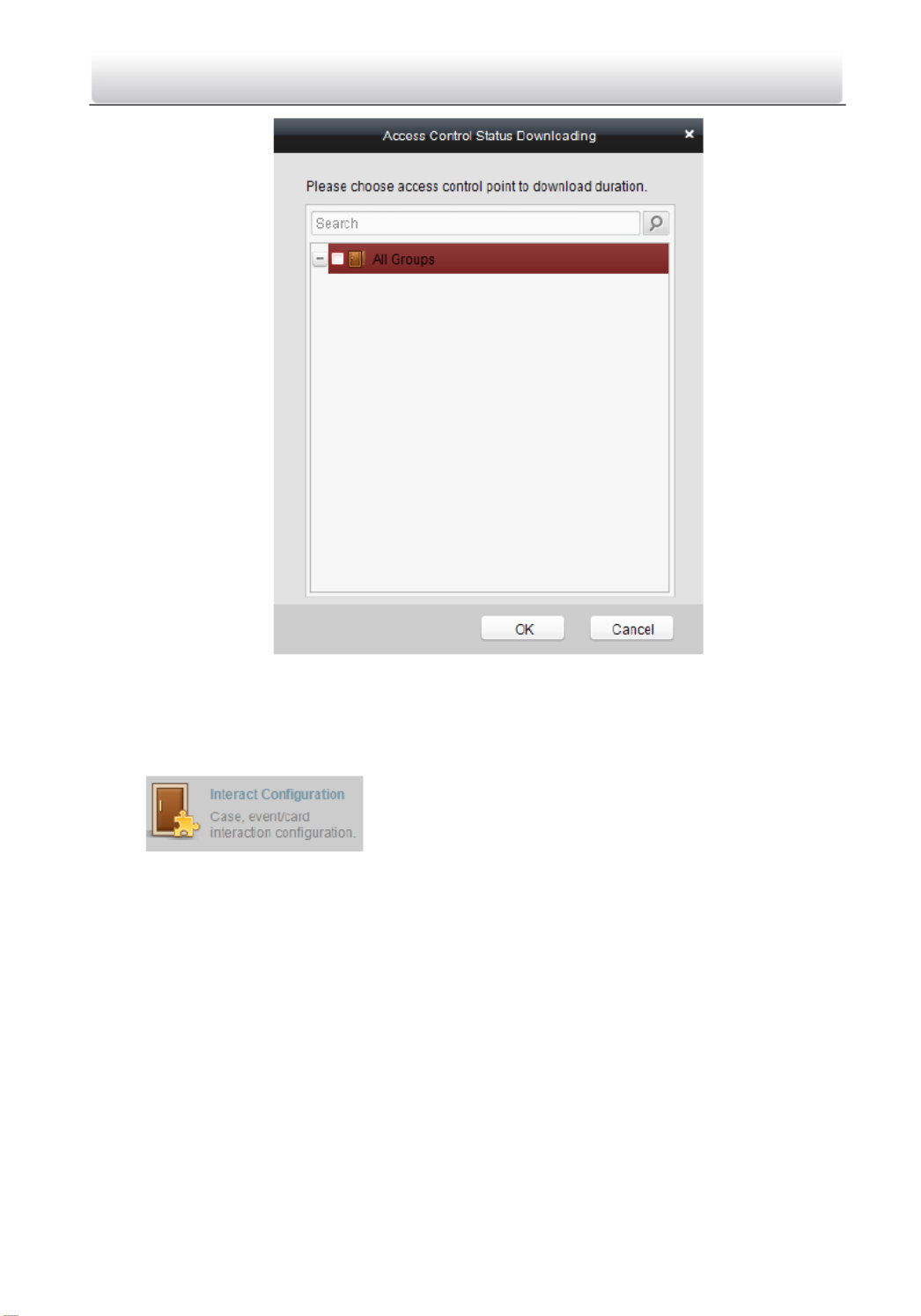
Access Control Terminal·
·
·
··User Manual
66
8. Select a control point and click to download the settings to the system OK .
7.3.5 Interact Configuration
Click on the control panel of the software to enter the
interact configuration interface.

Access Control Terminal·
·
·
··User Manual
67
In this interface, you can set alarm linkage modes of the access host, including
case trigger, event card interact, and client interact.
Case Trigger
Purpose:
The case (refer to the triggers of the controller) can be linked to some actions
(e.g., alarm output, host buzzer) when it is triggered.
Steps:
1. Click the button to enter the case trigger interface,
and select a case.

Access Control Terminal·
·
·
··User Manual
68
2. Check the checkbox of the corresponding linkage acons and set the
property as Trigger to enable this funcon.
Host Buzzer: The audible warning of controller will be triggered.
Reader Buzzer: The audible warning of card reader will be triggered.
Alarm Output: The alarm output will be triggered for nocaon.
Door (Open/Close): The door will be open or closed when the case is
triggered.
3. Click the buon. Save
4. Click the buon to take eect of the new sengs. Apply
The Door cannot be congured as open or closed at the same me.
Event Card Interact
In the Interact Conguraon interface, click the Event Card Interact button to
enter the setngs interface.
Event Linkage
In the Event Interact interface, the linkage alarm acon, aer triggering alarm
event, can be set. The alarm event can be divided into four types: event device,
event input alarm, door event, and card reader event.
Steps:
1. Click the button to enter the event card interface
2. Select the host to be set from the host list.

Access Control Terminal·
·
·
··User Manual
69
3. Click the buon to start seng the event linkage .
4. Click the radio buon of the event linkage, and select the event type from
the dropdown list.
5. Set the linkage target, and set the property as Trigger to enable this
funcon.
Host Buzzer: The audible warning of controller will be triggered.
Snapshot: e real-me capture will be triggered. Th
Reader Buzzer: The audible warning of card reader will be triggered.
Alarm Output: The alarm output will be triggered for nocaon.
Door: The door status of open, close, normally open, and normally close
will be triggered.
6. Click the buon to save parameters.
7. Click the buon to download the updated parameters to the local Apply
memory of the device.
The door status of open, close, normally open, and normally close cannot
be triggered at the same me.
Models DS-K1T802M and DS-K1T802E do not support the snapshot
funcon.
Card Linkage
In the Event Interact interface, the linkage alarm acon, aer triggering the
card number, can be set.

Access Control Terminal·
·
·
··User Manual
70
Steps:
1. Click the button to enter the event card interface
2. Select the host to be set from the host list.
3. Click the buon to start seng the event linkage.
4. Click the radio buon of card linkage, and input the card number.
5. Select the event source, and check the checkbox of the card reader s serial ’
number.
6. Set the linkage target, and set the property as Trigger to enable this
funcon.
Controller Buzzer: The audible warning of controller will be triggered.
Snapshot: The real-me capture will be triggered.
Reader Buzzer: The audible warning of card reader will be triggered.
Alarm Output: The alarm output will be triggered for nocaon.
Door: The door status of open, close, normally open, and normally close
will be triggered.
7. Click the buon to save parameters.
8. Click the buon to download the updated parameters to the local Apply
memory of the device.

Access Control Terminal·
·
·
··User Manual
71
The door status of open, close, normally open, and normally close cannot
be triggered at the same time.
Models DS-K1T802M and DS-K1T802E do not support the snapshot
function.
7.3.6 Access Permission Configuration
Click the icon on the control panel to enter the
interface.
Access Permission Settings
Purpose:
You can allocate permission for people/department to enter/exist the control
points (doors) in this section.
Steps:
1. Enter the page. Permission
2. Click on icon on the upper-left side of the page to enter
the page.Add Permission

Access Control Terminal·
·
·
··User Manual
72
3. Select an adding type in the Select Type interface.
By Person: you can select people from the list to enter/exit the door.
By Department: You can select departments from the list to
enter/exit the door. Once the permission is allocated, all the people in
this department will have the permission to access the door.
By Access Control Point: You can select doors from the door list for
people to enter/exit.
By Door Group: You can select groups from the door list for people to
enter/exit. The permission will take effect on the door in this group.
4. Click to enter the interface. Next Permission Settings

Access Control Terminal·
·
·
··User Manual
73
5. Click on the dropdown menu to select a schedule template for the
permission.
The schedule template must be configured before any permission settings.
Refer to Section 7.3.3 Schedule Template for detailed configuration guide.
6. Select people/ department and corresponding doors/door groups from the
appropriate lists.

Access Control Terminal·
·
·
··User Manual
74
The lower-level of department will also be selected if the highest-level of
department is selected,
7. Click the button to complete the permission adding. Done
8. Click to enter the page. Download Permission

Access Control Terminal·
·
·
··User Manual
75
9. Select a control point and click the button, to enter the download result OK
interface, to download the permission to the device.
Access Permission Searching
Purpose:

Access Control Terminal·
·
·
··User Manual
76
After the permission settings being completed, you can search and view
permission assigning condition on the searching interface.
Steps:
1. Enter the page. Permission
2. Enter the search criteria (main type/minor type/Keyword ).
3. Click to get the search results. Search
You can click on the search criteria panel to clear all the Reset
displayed search results.
Permission Deleting
Steps:
1. Follow steps 1-3 in the Permission Searching section to search for the
permission needs to be deleted.
2. Select the permission from the results list.

Access Control Terminal·
·
·
··User Manual
77
You can press the Ctrl or Shift key on the keyboard,
3. Click the button to delete the permission. Delete Permission
4. Click to enter the page. Download Permission
5. Select a control point and click the button to download the deletion OK
operation to the device.
7.3.7 Aendance Management
Purpose:
On the attendance management interface, various functions can be
implemented such as shift group management, shift management, holiday
management, shift schedule, and so on.

Access Control Terminal·
·
·
··User Manual
78
Click the icon on the control panel to enter the
interface.
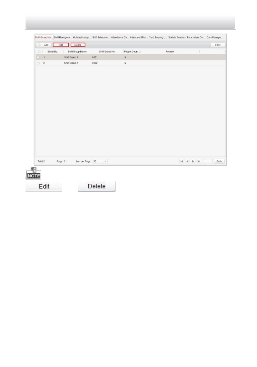
Shift Group Management
Purpose:
On the shi group management interface, you can add, edit, and delete shi
groups for aendance management.
Steps:
1. Click the buon to pop up the shi group formaon
window.

Access Control Terminal·
·
·
··User Manual
79
2. Enter the shi group name, and add the buon on the
person list area to add pop up the person adding window.

Access Control Terminal·
·
·
··User Manual
80
3. Check the checkbox(es) of persons to be added and click the
buon and return to the shi group sengs interface.
To delete the added person, check the person from the person list, and
click the buon.
4. Click the buon to complete the operaon.
Access Control Terminal·
·
·
··User Manual
81
You can edit and delete the added shi groups by clicking the
and buons.
Shift Management
Press the tab to enter the shi management interface. Shi Management

Access Control Terminal·
·
·
··User Manual
82
There are two kinds of shis in this interface: , and Normal Shi Man-Hour
Shi.
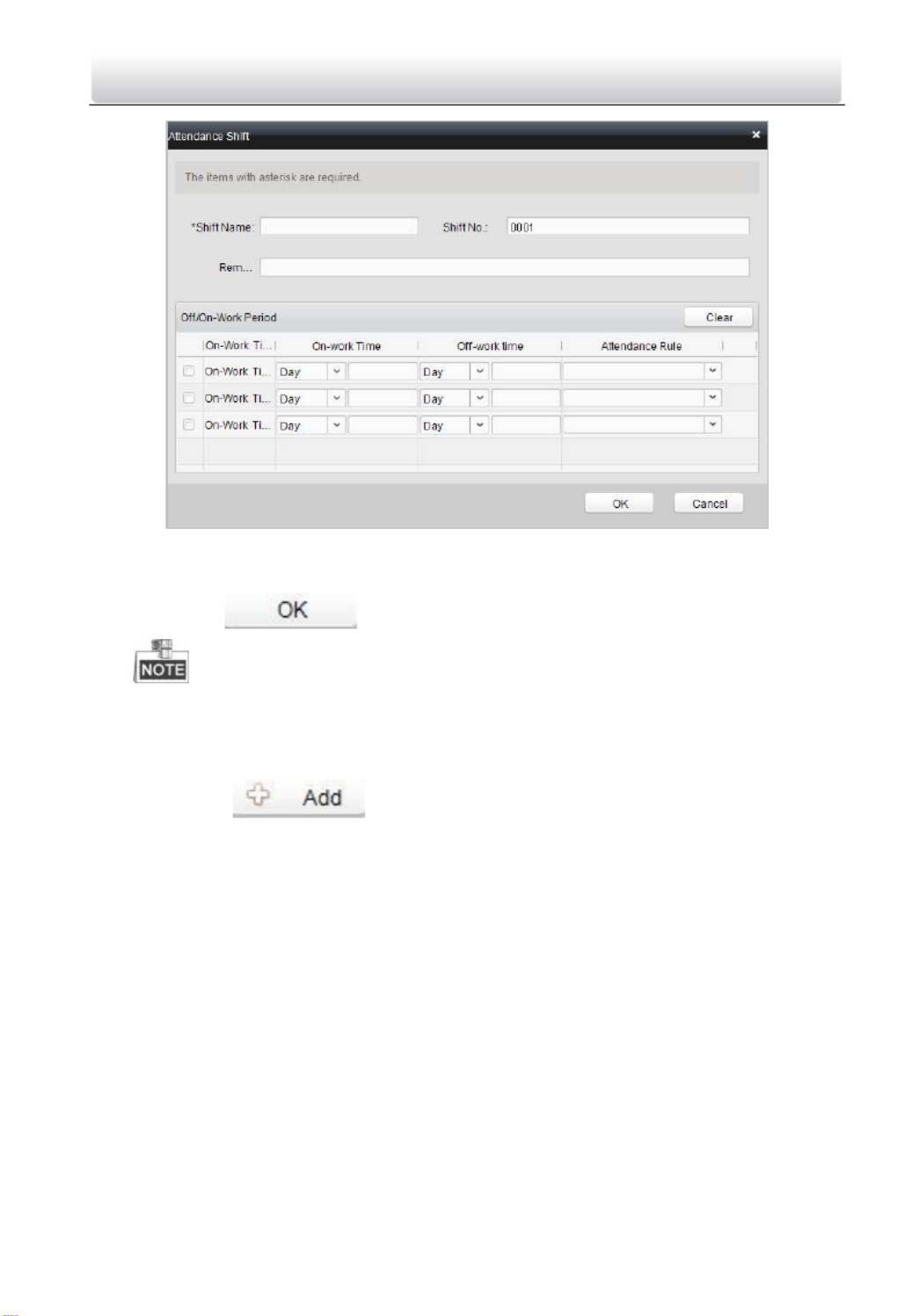
Normal Shi
Seng Attendance Rule
Steps:
1. Click the buon to pop up the aendance rule seng
window.
Access Control Terminal·
·
·
··User Manual
84
2. Set a shi name.
3. Set on-work duraon for the shi, and select the aendance rule.
4. Click the buon to complete the operaon.
The format of on-work me and o-work me should be 00:00 to
23:59.
Man-Hour Shi
Steps:
1. Click the buon to pop up the man-hour shi seng
window.

Access Control Terminal·
·
·
··User Manual
85
2. Set a shi name, and daily working duraon.
3. (Oponal) Check the checkbox of latest on-work me, and set the latest
on-work me.
4. (Oponal) Set the disregard man-hour period.
5. Click the buon to complete the operaon.
Holiday Management
Press the tab to enter the holiday management Holiday Management
interface.

Access Control Terminal·
·
·
··User Manual
87
3. Set the start date and end date, select the date of week, and click the
buon.
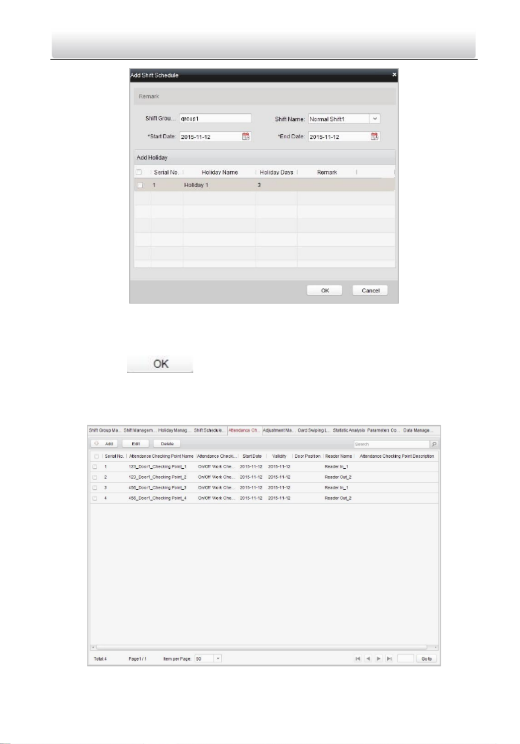
Shift Schedule Management
Press the tab to enter the shi schedule Shi Schedule Management
management interface.
Steps:
1. Press a tab of shi group on the shi group list.
2. Click the buon to pop up the shi schedule sengs
window.
Access Control Terminal·
·
·
··User Manual
88
3. Select the shi name from the drop-down list.
4. Set the start data and end data.
5. (Oponal) Check the checkbox of holiday to add the holiday shi.
6. Click the buon to complete the operaon.
Attendance Check Point Management
Press the Attendance Check Point Management tab to enter the attendance
check point management interface.

Access Control Terminal·
·
·
··User Manual
89
Adding Aendance Check Point
Steps:
1. Check the checkbox of a checking point, and click the buon
to pop up the aendance checking point eding window.
2. Edit the aendance checking point name, start date, validity, and
aendance checking point type, controller name, door posion, and
reader name.
3. Click the buon to complete the operaon.
Adding Aendance Check Point
Check the checkbox of a checking point and click the buon to
delete the added checking point.
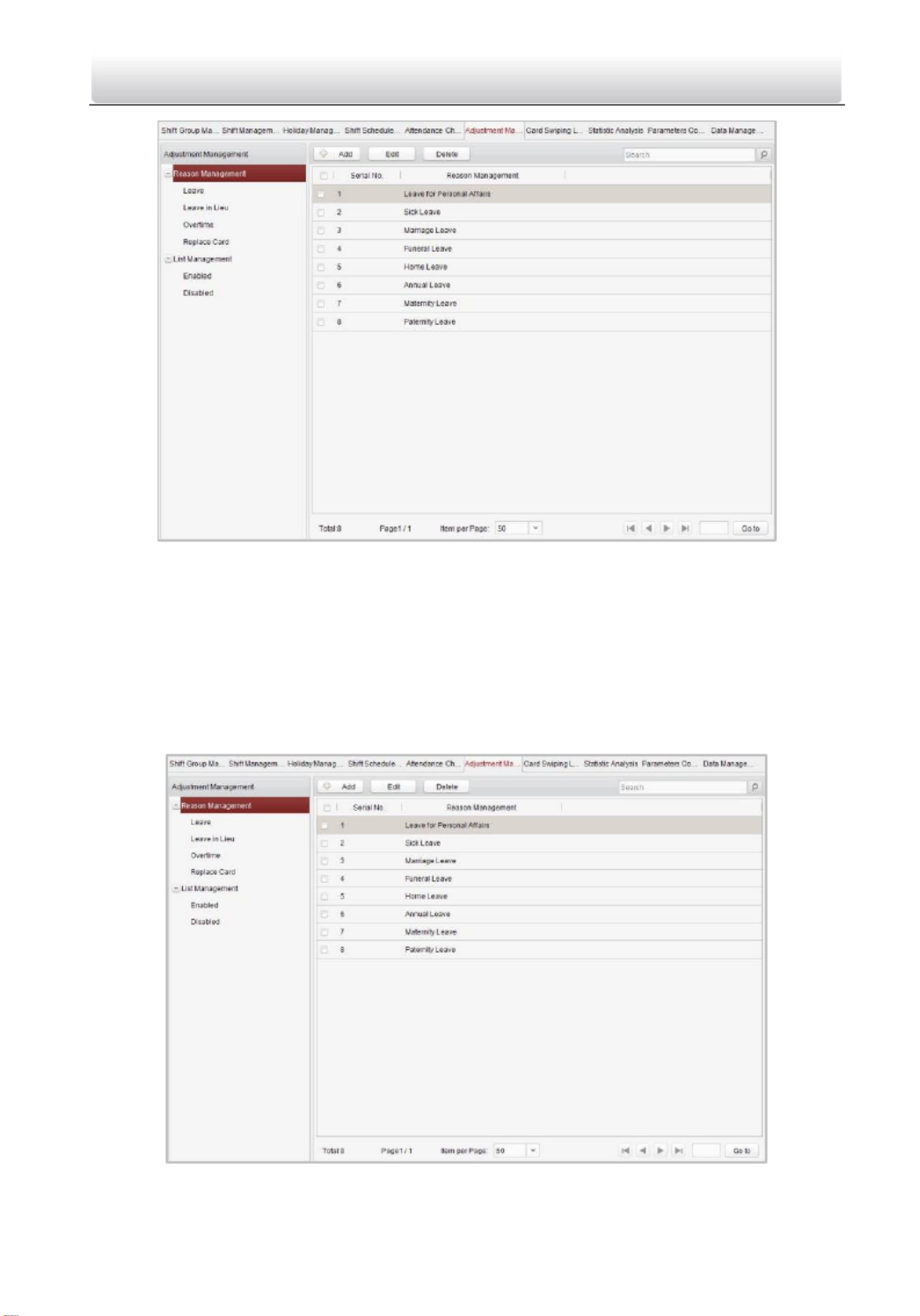
Adjustment Management
Press the tab to enter the adjustment management Adjustment Management
interface.
Access Control Terminal·
·
·
··User Manual
90
On this interface, Reason Management List Management and can be realized.
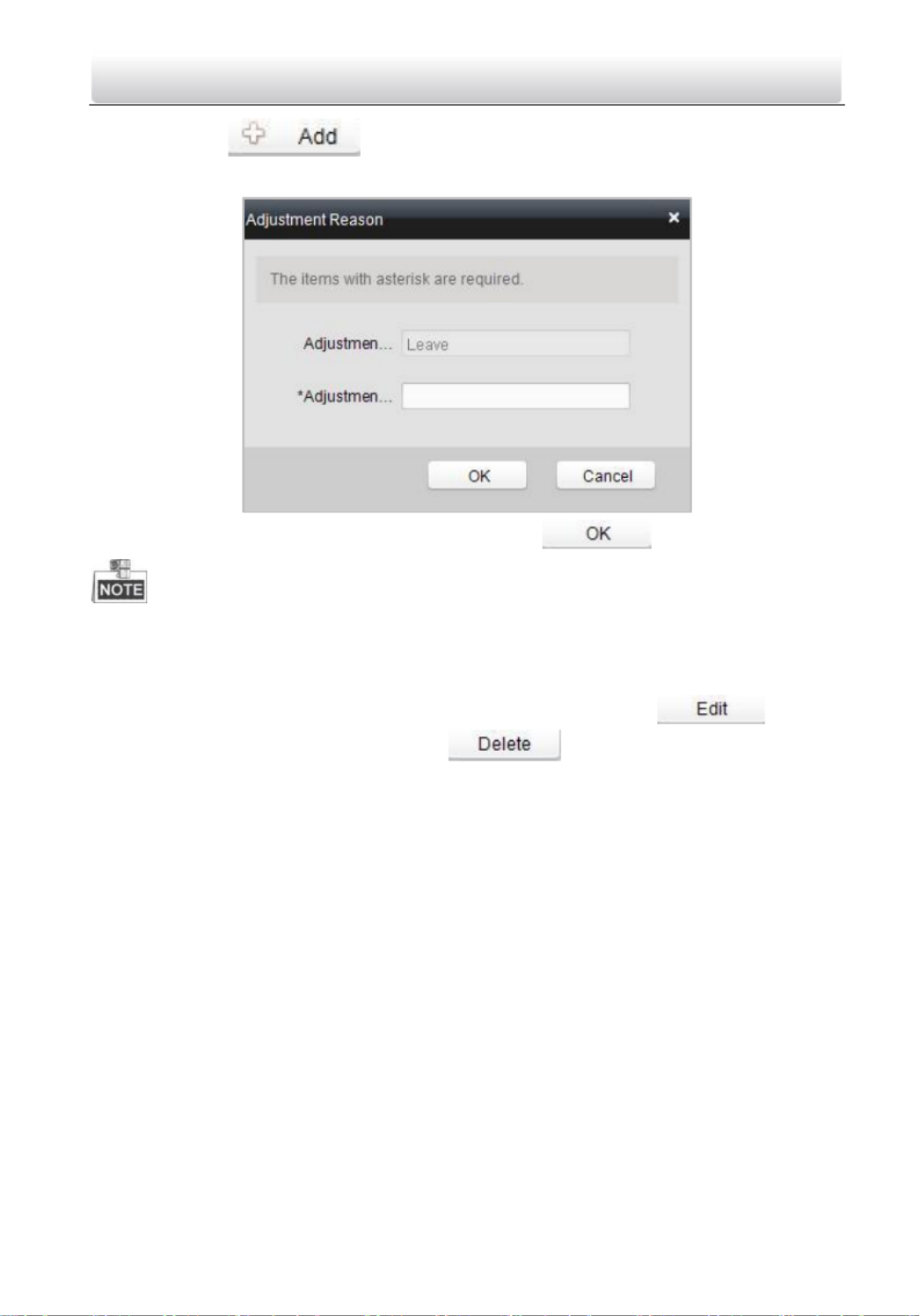
Reason Management
Leave
Purpose:
You can add, edit, and delete reasons for leave on the leave interface.
Steps:
1. Press the leave tab to enter the leave interface.
Access Control Terminal·
·
·
··User Manual
91
2. Click the buon to pop up the adjustment reason adding
dialog box.
3. Enter the adjustment reason, and click the buon.
• The default adjustment reasons include leave for personal aairs, sick
leave, marriage leave, funeral leave, home leave, annual leave, maternity
leave, and paternity leave.
• You can check the checkbox of a reason and click the buon
to edit the reason, and click the buon to delete the reason.
Leave in Lieu
Steps:
1. Press the leave in lieu tab to enter the leave- -lieu interface. in

Access Control Terminal·
·
·
··User Manual
92
2. Click the buon to pop up the adjustment reason adding
dialog box.
3. Enter the adjustment reason, and click the buon.
• The default adjustment reasons for leave in lieu include overme, and
business trip.
• You can check the checkbox of a reason and click the buon
to edit the reason, and click the buon to delete the reason.

Access Control Terminal·
·
·
··User Manual
93
Overme
Steps:
1. Press the overme tab to enter the overme interface.
2. Click the button to pop up the adjustment reason adding
dialog box.
3. Enter the adjustment reason, and click the buon.
• The default adjustment reasons for overme include work requirement,
working day overme, rest day overme, and holiday overme.

Access Control Terminal·
·
·
··User Manual
94
• You can check the checkbox of a reason and click the
buon to edit the reason, and click the buon to delete
the reason.
Replace Card
Steps:
1. Press the replace card tab to enter.
2. Click the buon to pop up the adjustment reason adding
dialog box.
3. Enter the adjustment reason, and click the buon.

Access Control Terminal·
·
·
··User Manual
95
• The default adjustment reasons for card replacing include forget to swipe
card, aendance card lost, device fault, shi adjustment, and business
trip.
• You can check the checkbox of a reason and click the buon
to edit the reason, and click the buon to delete the reason.
List Management
Enabling
Steps:
1. Press the tab to enter the enabled list interface. Enabled
2. Click the button.

Access Control Terminal·
·
·
··User Manual
96
3. Select the radio buon of adjustment type: leave, leave in lieu, overme,
and replace card.
Leave, Leave in Lieu, and Overme
1) Select the adjustment reason from the drop-down list.
2) Click the buon to pop up the person adding window.

Access Control Terminal·
·
·
··User Manual
97
3) Select the person and click the buon.
4) Set the me period.
Replace Card
1) Select the radio buon of replace card.
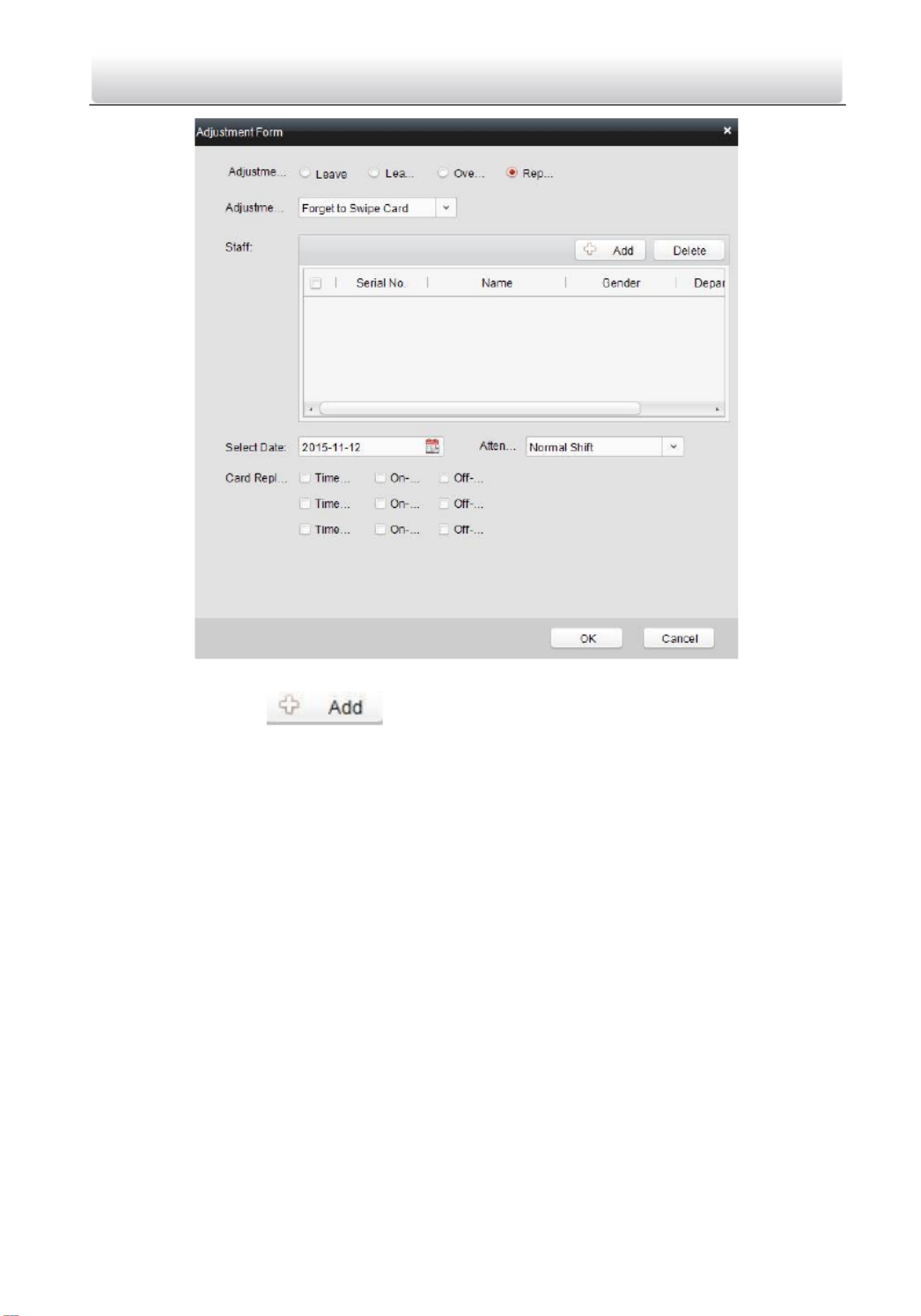
Access Control Terminal·
·
·
··User Manual
98
2) Select the adjustment reason from the drop-down list.
3) Click the buon to pop up the person adding window.
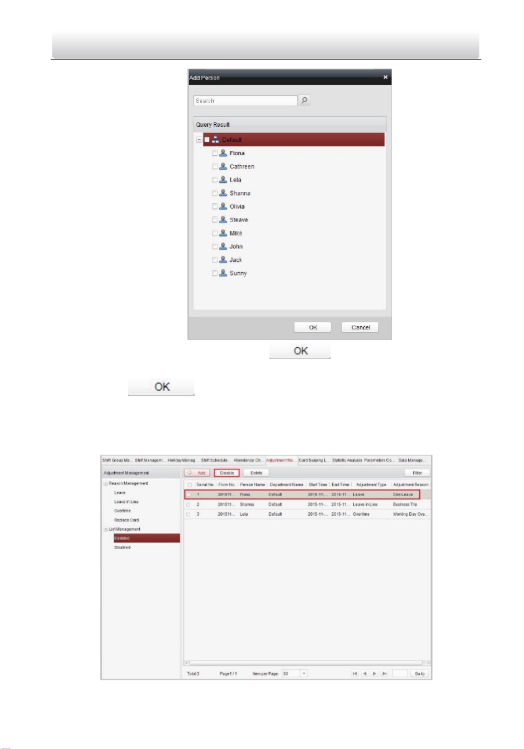
Access Control Terminal·
·
·
··User Manual
99
4) Select the person and click the buon.
5) Set the date, attendance shi, and card replacing me.
4. Click the buon to complete the operaon
Disabling
Steps:
1. Check the checkbox of a piece of enabled informaon.

Access Control Terminal·
·
·
··User Manual
100
2. Click the buon to disable the informaon.
3. Press the tab and the disabled informaon will be listed on the Disabled
disabled interface.
Card Swiping Log Query
Press the tab to enter the card swiping log searching Card Swiping Log Query
and viewing interface.
• You can search the card swiping log by two query types: By Shi Group,
and By Department.

Access Control Terminal·
·
·
··User Manual
101
• You can search the card swiping log by group name.
• You can search the card swiping log by start date and end date.
• You can restrict the query scope: , or All, First Last.
Statistic Analysis
Press the Stasc Analysis tab to enter the stasc analysis interface.
On the stasc analysis interface, you can search the aendance analysis table,
aendance result stasc table, and aendance rate stasc table.
Aendance Analysis Table
Press the Aendance Analysis Table tab to enter the aendance analysis
interface.

Access Control Terminal·
·
·
··User Manual
102
• You can search the aendance stascs by dierent shi type: Normal
Shi Man-Hour Shi, or .
• You can search the aendance stascs by department.
• You can search the aendance stascs by start date and end date.
Aendance Result Stasc Table
Press the Attendance Result Stasc Table tab to enter the aendance result
analysis interface .
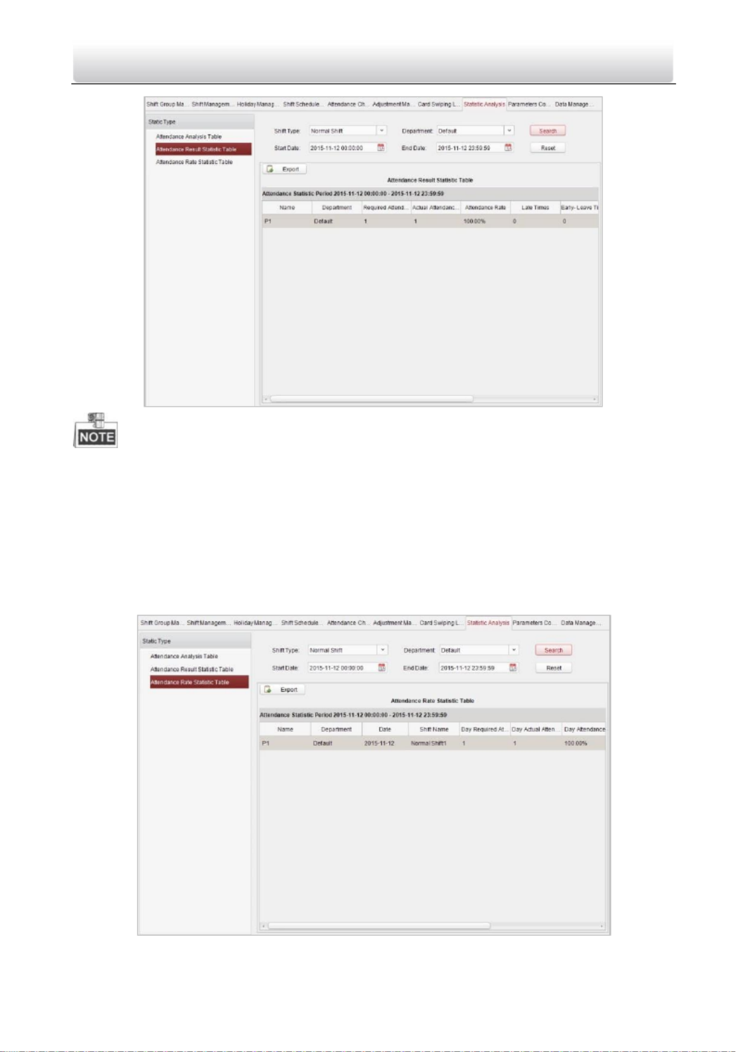
Access Control Terminal·
·
·
··User Manual
103
• You can search the aendance result stascs by dierent shi type:
Normal Shi Man-Hour Shi, or .
• You can search the aendance result stascs by department.
• You can search the aendance result stascs by start date and end date.
Aendance Rate Stasc Table
Press the Attendance Rate Stasc Table tab to enter the aendance rate
analysis interface.
Produktspezifikationen
| Marke: | Hikvision |
| Kategorie: | Zugangskontrollsystem |
| Modell: | DS-K1T802M |
Brauchst du Hilfe?
Wenn Sie Hilfe mit Hikvision DS-K1T802M benötigen, stellen Sie unten eine Frage und andere Benutzer werden Ihnen antworten
Bedienungsanleitung Zugangskontrollsystem Hikvision

19 September 2024
2 September 2024
2 September 2024
2 September 2024
1 September 2024
1 September 2024
31 August 2024
23 August 2024
23 August 2024
23 August 2024
Bedienungsanleitung Zugangskontrollsystem
- Zugangskontrollsystem Approx
- Zugangskontrollsystem Bosch
- Zugangskontrollsystem Eminent
- Zugangskontrollsystem Abus
- Zugangskontrollsystem Yale
- Zugangskontrollsystem Burg Wächter
- Zugangskontrollsystem Marmitek
- Zugangskontrollsystem Honeywell
- Zugangskontrollsystem Techly
- Zugangskontrollsystem Safescan
- Zugangskontrollsystem ASSA ABLOY
- Zugangskontrollsystem Viking
- Zugangskontrollsystem APC
- Zugangskontrollsystem Delta Dore
- Zugangskontrollsystem EverFocus
- Zugangskontrollsystem GeoVision
- Zugangskontrollsystem Provision ISR
- Zugangskontrollsystem Satel
- Zugangskontrollsystem Steren
- Zugangskontrollsystem ACTi
- Zugangskontrollsystem Vimar
- Zugangskontrollsystem ZKTeco
- Zugangskontrollsystem Iogear
- Zugangskontrollsystem Dahua Technology
- Zugangskontrollsystem Panduit
- Zugangskontrollsystem Speco Technologies
- Zugangskontrollsystem Atlantis Land
- Zugangskontrollsystem HID Identity
- Zugangskontrollsystem Axis
- Zugangskontrollsystem Suprema
- Zugangskontrollsystem Gewiss
- Zugangskontrollsystem ETiger
- Zugangskontrollsystem ONE Smart Control
- Zugangskontrollsystem SOREX
Neueste Bedienungsanleitung für -Kategorien-

8 Oktober 2024
3 Oktober 2024
1 Oktober 2024
1 Oktober 2024
1 Oktober 2024
1 Oktober 2024
1 Oktober 2024
1 Oktober 2024
1 Oktober 2024
1 Oktober 2024