Festo CPX-E-CEC-M1 Bedienungsanleitung
Festo
DJ Ausrüstung
CPX-E-CEC-M1
Lesen Sie kostenlos die 📖 deutsche Bedienungsanleitung für Festo CPX-E-CEC-M1 (7 Seiten) in der Kategorie DJ Ausrüstung. Dieser Bedienungsanleitung war für 29 Personen hilfreich und wurde von 2 Benutzern mit durchschnittlich 4.5 Sternen bewertet
Seite 1/7
CPX-E
Automation system
Festo SE & Co. KG
Ruiter Straße 82
73734 Esslingen
Germany
+49 711 347-0
www.festo.com
Operating instruction
8192618
2023-09b
[8192620]
8192618
Translation of the original instructions
© 2023 all rights reserved to Festo SE & Co. KG
IO-Link is a registered trademark of its respective trademark holder in certain
countries.
1 About this document
This document describes the use of the above-mentioned product family.
Certain aspects of use are described in other documents and must be observed
è1.1 Applicable documents.
1.1 Applicable documents
All available documents for the product
èwww.festo.com/sp.
Document Content
Automation system CPX-E Manual Detailed description of the automation system
CPX-E
Operating instructions and manuals for the CPX-E
modules in the automation system CPX-E
Information on using the CPX-E modules
Tab. 1: Applicable documents
1.2 Product version
This document refers to the automation system CPX-E with CPX-E modules.
The product version can be identified from the product labelling or with the help
of appropriate software from Festo.
Software suitable for determining the product version is available from Festo in
the Support Portal èwww.festo.com/sp.
Information on using the software can be found in the integrated Help function.
1.3 Product labelling
The CPX-E modules are labelled on the left side. The product labelling is described
in the documentation supplied with the product.
1.4 Specified standards
Version
DIN46228-1:1992-08 EN60529:2013-10
DIN46228-4:1990-09 EN60715:2001-09
EN60068-2-27:2010-02 IEC60204-1:2014-10
Tab. 2: Standards specified in the document
1.5 UL certification
In combination with the UL inspection mark on the product, the information in this
section must also be observed in order to comply with the certification conditions
of Underwriters Laboratories Inc. (UL) for USA and Canada.
UL certification information
Product category code NRAQ/NRAQ7
File number E239998
Considered standards UL 61010-1, 3rd Edition, May 11, 2012, revised April 29, 2016
CAN/CSA-C22.2 No. 61010-1-12, 3rd Edition, Revision dated April
29, 2016
UL 61010-2-201, 1st Edition, Revised February 20, 2017
CSA-C22.2 No. 61010-2-201:14, 1st Edition, Issue date January 01,
2014
UL mark
Tab. 3: UL certification information
–Technical data and environmental conditions may be subject to change in order
to comply with Underwriters Laboratories Inc. (UL) certification requirements
for the USA and Canada.
Note deviations Technical data.è
–The unit shall be supplied by a power source which fulfils the requirements
on a limited-energy circuit in accordance to IEC/EN/UL/CSA 61010-1 or on
a Limited Power Source (LPS) in accordance to IEC/EN/UL/CSA 60950-1 or
IEC/EN/UL/CSA 62368-1 or a Class 2 circuit in accordance to NEC or CEC.
Unauthorised access to the device can cause damage or malfunctions.
When connecting the device to a network:
Protect the network against unauthorised access.
Measures to protect the network include:
• Firewall
• Intrusion Prevention System (IPS)
• Network segmentation
• Virtual LAN (VLAN)
• Virtual private Network (VPN)
• Security at physical access level (port security)
For additional information Guidelines and standards for security in informationè
technology, e.g. IEC62443, ISO/IEC27001.
An access password only protects against unintentional modification.
NOTICE
Modules with Ethernet interfaces should only be operated in networks if all con-
nected network components are supplied by PELV circuits or integrated circuits
with equivalent protection.
2 Safety
2.1 Safety instructions
–Take into consideration the legal regulations for the installation location.
–Use the product only within the defined values
è13Technical data.
–Observe the identifications on the product.
–Observe further applicable documents.
–Store the product in a cool, dry environment protected from UV and corrosion.
Keep storage times short.
–Before working on the product: switch off the power supply and secure it
against being switched on again.
–Comply with the handling specifications for electrostatically sensitive devices.
2.2 Intended use
The product described in this document is intended only for use within a pro-
tected range in the vicinity of a machine and/or automated system.
Use the product only as follows:
–Use only in an industrial environment. Outside industrial environments, e.g.in
commercial and residential/mixed-use areas, it may be necessary to take meas-
ures to suppress radio interference.
–Use only in combination with modules and components that are approved for
the applicable product variant èwww.festo.com/catalogue.
–Only use the product if it is in perfect technical condition.
–Only use the product in its original condition without unauthorised modifica-
tions. Only the conversions or modifications described in this and the further
applicable documents are permitted.
2.3 Training of qualified personnel
Work on the product should only be conducted by qualified personnel. The quali-
fied personnel must be familiar with installation of electrical control systems.
3 Additional information
–Contact the regional Festo contact if you have technical problems
èwww.festo.com.
–Accessories and spare parts èwww.festo.com/catalogue.
Firmware, software or configuration files èwww.festo.com/sp.
More information Content
Device description files Definition of the modules in an automation
system CPX-E for integration into the higher-level
controller
Documentation for the higher-order controller
and the additional devices in the network
Information on commissioning and parameterisa-
tion of the components
Tab. 4: More information
4 Product overview
4.1 Function
The Automation system CPX-E is a modular system for the connection of electrical
peripherals. The individual modules in an Automation system CPX-E are used,
forexample, to detect sensor signals and to control actuators. Using a bus
module or controller, the Automation system CPX-E can be connected to a higher-
order controller through a network or operated autonomously. Various interfaces
and functions are available for diagnostics.
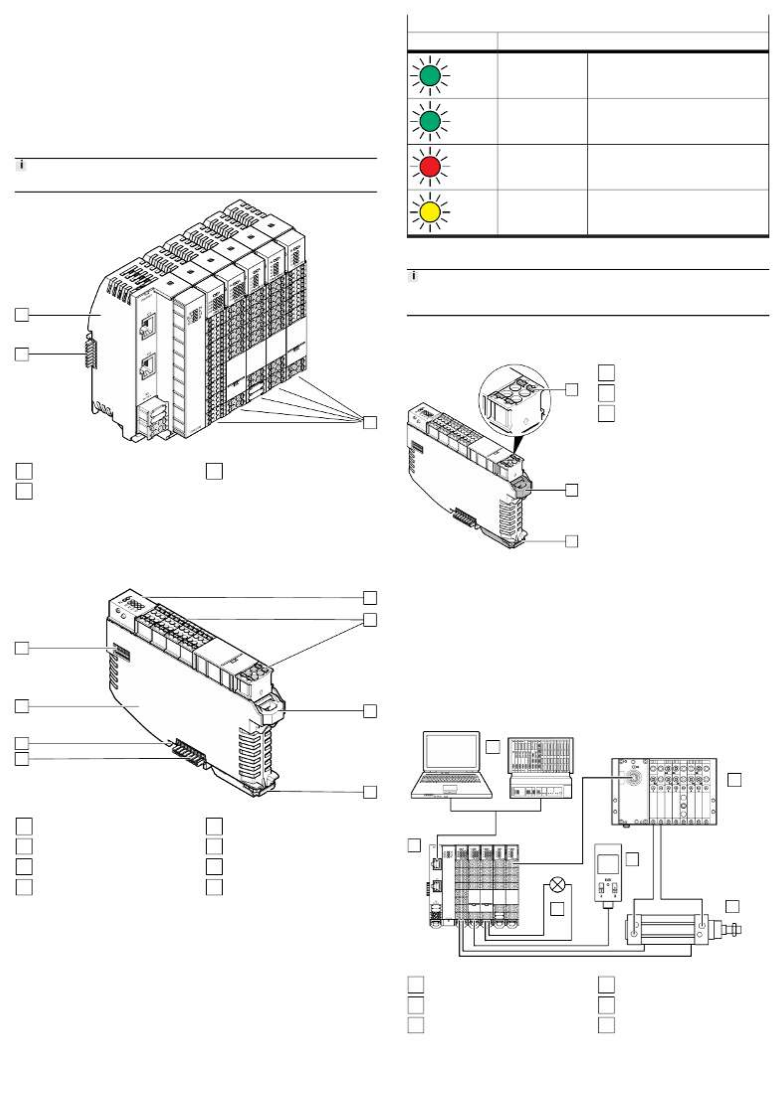
4.2 Structure
4.2.1 Product design
4.2.1.1 Automation system CPX-E
The automation system CPX-E consists of a bus module or controller on the
left side and at least one I/O module for signal processing. The modules are
connected by linkage elements. The contacts of both external linkage elements
are protected by end supports.
2end supports are included with each bus module or controller.
1
2
3
Fig. 1: Structure of the automation system CPX-E (example)
1
Input and output modules
2
Linkage element
3
Bus module, here CPX-E-PN
4.2.1.2 CPX-E modules
The CPX-E modules are designed in such a way that it is possible to replace
individual components without dismantling the automation system CPX-E.
Terminal strips can be removed from the module by disengaging the interlock. An
individual module can be removed from the system by disengaging the module
interlock. The linkage element remains on the H-rail.
1
2
3
4
5
6
7
8
Fig. 2: Module design (example)
1
LED indicators
2
Terminal strips
3
Terminal strip interlock
4
Module interlock
5
Linkage element
6
Functional earth contact FE
7
Housing
8
DIL switch (module-dependent)
4.2.2 Display components
The CPX-E modules have LED indicators specific to the module or to the network
and system:
–LED indicators specific to the module and network are described in the docu-
mentation for the that module.
–The overview of the system-specific LED indicators is shown in the following
table èTab. 5 System-specific LED indicators.
–The response of the system-specific LED indicators is described in:
–è11Diagnostics and fault clearance
–"Automation system CPX-E manual" è1.1 Applicable documents
System-specific LED indicators
LED Meaning
PS (green) Power System Monitoring of the operating voltage supply
UEL/SEN
PL (green) Power Load Monitoring of the logic and load voltage supply
UOUT
SF (red) System Failure System errors1)
M (yellow) Modify Force mode active or system start with saved
parameterisation and saved system configuration
has been set.
1) Display of 3 error classes by different flashing responses
Tab. 5: System-specific LED indicators
Detailed information on the error classes can be found in the "Automation system
CPX-E manual" è1.1 Applicable documents.
4.2.3 Control elements
The CPX-E module has interlocks for engaging and disengaging the module, con-
nector plugs and connected conductors.
1
2
3
Fig. 3: Control elements
1
Spring-loaded terminal interlock
2
Terminal strip interlock
3
Module interlock
4.2.4 Connecting elements
4.2.4.1 Connecting the automation system CPX-E
The individual modules of the automation system CPX-E are connected to each
other by means of the linking elements. The contact to the linking element is
established when the modules are hung into the H-rail
è6 Mounting.
If a module is removed, the connection to the other modules is interrupted.
4.2.4.2 Connecting the peripherals
For the connection of peripheral equipment, the modules have plug connectors
with spring-loaded terminals è7 Installation.
5 Functional example
1
2
3
4
5
6
Fig. 4: Functional example
1
Higher-order controller
2
Valve terminal VTUG
3
Standards-based cylinder with
proximity switches for position
sensing
4
Flow sensor
5
Indicator light
6
Automation system CPX-E with
bus module and I/O modules
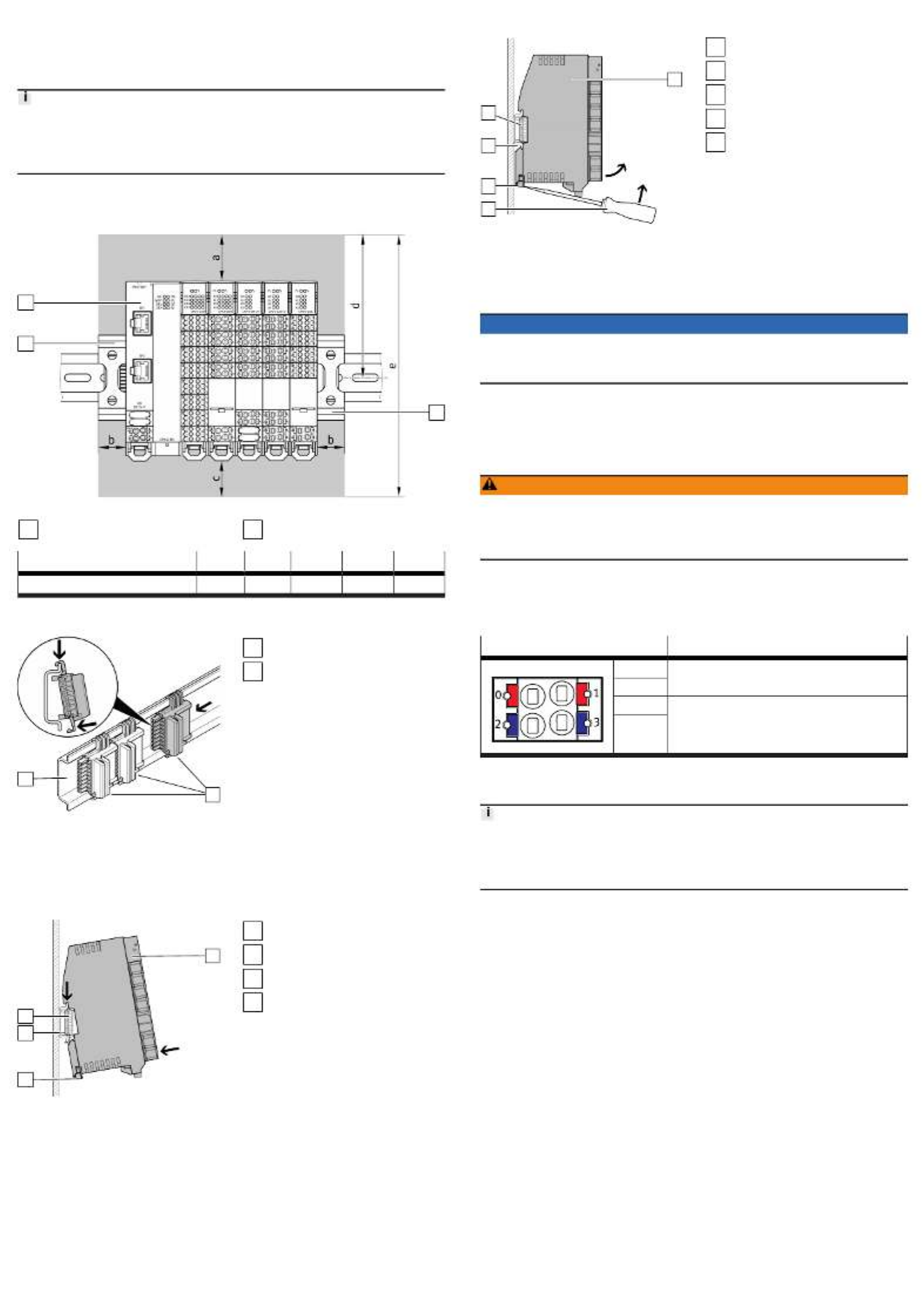
6 Mounting
6.1 H-rail mounting
The modules are mounted on an H-rail 35 mm × 7.5 mm in accordance with
EN60715.
When selecting screws for H-rail mounting, a distance of 3mm between the H-rail
and the linkage elements must be maintained.
The distance between the retaining screws for mounting the H-rail must not
exceed a maximum of 50mm.
6.2 Mounting clearances
To ensure sufficient ventilation of the modules, maintain the following minimum
clearances when mounting the automation system CPX-E.
1
2
2
Fig. 5: Mounting clearances
1
Automation system CPX-E
2
End support
Dimension a b c d e
Minimum clearance [mm] 40 20 30 106 195
Tab. 6: Minimum clearances
6.3 Fitting linkage element
1.
2.
3.
1
2
Fig. 6: Fitting linkage element
1
Linkage elements
2
H-rail
1. Place the linkage element in the correct position on the H-rail.
2. Clip the linkage element onto the H-rail.
3. Push the linkage elements towards one another until they latch together.
6.4 Modules
6.4.1 Fitting and locking the module
1.
2.
1
2
3
4
Fig. 7: Fitting module
1
Module
2
Module interlock
3
H-rail
4
Linkage element
1. Place the module above the linkage element(s) on the H-rail:
–Two linkage elements are required per module for bus modules.
–Four linkage elements are required per controller for controllers.
2. Press the module onto the H-rail until the module interlock locks into place.
6.4.2 Disengaging and removing the module
1
2
3
4
5
Fig. 8: Disengaging module
1
Module
2
Slotted head screwdriver
3
Module interlock
4
H-rail
5
Linkage element
1. Disengage the module interlock (e.g.with a slotted head screwdriver).
2. Tilt the module upward and remove it from the H-rail.
7 Installation
NOTICE
Malfunction due to electromagnetic interference.
• Connect shielding to the functional earth connection FE.
• Connect the H-rail to the earth potential with low impedance.
7.1 Power supply concept
The Automation system CPX-E uses separate voltages to supply the electronics
and sensors (UEL/SEN) and to supply outputs (UOUT). The equivalent voltage poten-
tials (+24VDC and 0VDC) are connected to each other in the terminal strips.
This enables the applicable voltage to be transferred from one module to the next.
WARNING
Risk of injury due to uncontrolled movements of the connected actuators.
A feedback loop through the sensor or actuator supply to the modules can supply
the automation systemCPX-E and lead to unwanted functions.
• Keep the range of movement of the connected actuators unobstructed.
Operating power supply UEL/SEN
The operating voltage supply UEL/SEN to supply the electronics and sensors is
fed in at the bus module or controller and distributed internally to the entire
Automation system CPX-E.
Connection [XD1], [XD2]1) Signal
0 +24VDC operating voltage supply UEL/SEN
1
2 0VDC operating voltage supply UEL/SEN
3
1) Connections XDx.0 and XDx.1 and also XDx.2 and XDx.3 are each connected to each other in the terminal
strip.
Tab. 7: Connection [XD1], [XD2]
To comply with the certification requirements of Underwriters Laboratories Inc.
(UL) for the USA and Canada, within the scope of UL/CSA, depending on the
current consumption, the parallel connection of the operating voltage supply to
[XD1] and [XD2] is required è13.3 Technical data for UL certification.
Load voltage supply UOUT
The load voltage supply UOUT to supply the outputs is fed directly to the module
separately for every module with outputs. In the following example with the
output module CPX-E-8DO this is the output module CPX-E-4AO-UI and the IO-Link
master module CPX-E-4IOL.
Produktspezifikationen
| Marke: | Festo |
| Kategorie: | DJ Ausrüstung |
| Modell: | CPX-E-CEC-M1 |
Brauchst du Hilfe?
Wenn Sie Hilfe mit Festo CPX-E-CEC-M1 benötigen, stellen Sie unten eine Frage und andere Benutzer werden Ihnen antworten
Bedienungsanleitung DJ Ausrüstung Festo

24 September 2024
Bedienungsanleitung DJ Ausrüstung
- DJ Ausrüstung Audio-Technica
- DJ Ausrüstung SilverCrest
- DJ Ausrüstung Roland
- DJ Ausrüstung TechniSat
- DJ Ausrüstung Yamaha
- DJ Ausrüstung Velleman
- DJ Ausrüstung Technaxx
- DJ Ausrüstung Denver
- DJ Ausrüstung König
- DJ Ausrüstung MarQuant
- DJ Ausrüstung Thomson
- DJ Ausrüstung Trevi
- DJ Ausrüstung Kenwood
- DJ Ausrüstung Pyle
- DJ Ausrüstung Auna
- DJ Ausrüstung Beyerdynamic
- DJ Ausrüstung Lenco
- DJ Ausrüstung Denon
- DJ Ausrüstung Mpman
- DJ Ausrüstung Pioneer
- DJ Ausrüstung Krüger And Matz
- DJ Ausrüstung Muse
- DJ Ausrüstung Technics
- DJ Ausrüstung BeamZ
- DJ Ausrüstung Akai
- DJ Ausrüstung Dual
- DJ Ausrüstung Kärcher
- DJ Ausrüstung Tascam
- DJ Ausrüstung Zoom
- DJ Ausrüstung Ricatech
- DJ Ausrüstung Sencor
- DJ Ausrüstung Fenton
- DJ Ausrüstung American DJ
- DJ Ausrüstung Gemini
- DJ Ausrüstung Power Dynamics
- DJ Ausrüstung Skytec
- DJ Ausrüstung Vonyx
- DJ Ausrüstung Wacom
- DJ Ausrüstung AVerMedia
- DJ Ausrüstung EnVivo
- DJ Ausrüstung NAD
- DJ Ausrüstung Behringer
- DJ Ausrüstung Numark
- DJ Ausrüstung Omnitronic
- DJ Ausrüstung ESI
- DJ Ausrüstung Eurolite
- DJ Ausrüstung Marantz
- DJ Ausrüstung Hercules
- DJ Ausrüstung Cambridge
- DJ Ausrüstung Ecler
- DJ Ausrüstung Monacor
- DJ Ausrüstung TEAC
- DJ Ausrüstung Thorens
- DJ Ausrüstung Alesis
- DJ Ausrüstung Korg
- DJ Ausrüstung Reloop
- DJ Ausrüstung TC Helicon
- DJ Ausrüstung ION
- DJ Ausrüstung NewStar
- DJ Ausrüstung Roadstar
- DJ Ausrüstung Swann
- DJ Ausrüstung Allen & Heath
- DJ Ausrüstung Motu
- DJ Ausrüstung American Audio
- DJ Ausrüstung Native Instruments
- DJ Ausrüstung Keith MCmillen
- DJ Ausrüstung Faderfox
- DJ Ausrüstung Pro-Ject
- DJ Ausrüstung Arturia
- DJ Ausrüstung AV:link
- DJ Ausrüstung Line 6
- DJ Ausrüstung McIntosh
- DJ Ausrüstung Pyle Pro
- DJ Ausrüstung PreSonus
- DJ Ausrüstung Qtx
- DJ Ausrüstung Rode
- DJ Ausrüstung IK Multimedia
- DJ Ausrüstung Victrola
- DJ Ausrüstung Apogee
- DJ Ausrüstung RME
- DJ Ausrüstung DAP Audio
- DJ Ausrüstung EVO
- DJ Ausrüstung Focusrite
- DJ Ausrüstung Icon
- DJ Ausrüstung M-Audio
- DJ Ausrüstung Martin
- DJ Ausrüstung Novation
- DJ Ausrüstung Serato
- DJ Ausrüstung Steinberg
- DJ Ausrüstung Sunstech
- DJ Ausrüstung Glorious
- DJ Ausrüstung Elektron
- DJ Ausrüstung Universal Audio
- DJ Ausrüstung Rane
- DJ Ausrüstung APart
- DJ Ausrüstung Fun Generation
- DJ Ausrüstung Denon DJ
- DJ Ausrüstung Nevir
- DJ Ausrüstung Vocopro
- DJ Ausrüstung IMG Stage Line
- DJ Ausrüstung DB Technologies
- DJ Ausrüstung Audient
- DJ Ausrüstung Konig & Meyer
- DJ Ausrüstung Pangea Audio
- DJ Ausrüstung Citronic
- DJ Ausrüstung Kenton
- DJ Ausrüstung SPL
- DJ Ausrüstung Brigmton
- DJ Ausrüstung Chauvet
- DJ Ausrüstung Sirus
- DJ Ausrüstung Music Hall
- DJ Ausrüstung Meris
- DJ Ausrüstung Vexus
- DJ Ausrüstung Atomix
- DJ Ausrüstung JTS
- DJ Ausrüstung Gravity
- DJ Ausrüstung Bigben Interactive
- DJ Ausrüstung Mixars
- DJ Ausrüstung Nektar
- DJ Ausrüstung IConnectivity
- DJ Ausrüstung ANT
- DJ Ausrüstung AudioQuest
- DJ Ausrüstung Ortofon
- DJ Ausrüstung Zomo
- DJ Ausrüstung Majestic
- DJ Ausrüstung PLAYdifferently
- DJ Ausrüstung Adam Hall
- DJ Ausrüstung Cheetah
- DJ Ausrüstung Fluid
- DJ Ausrüstung The T.mix
- DJ Ausrüstung Pepperdecks
- DJ Ausrüstung Monkey Banana
- DJ Ausrüstung MoFi
- DJ Ausrüstung Stanton
- DJ Ausrüstung MWM
- DJ Ausrüstung Suonobuono
- DJ Ausrüstung Formula Sound
- DJ Ausrüstung Genki Instruments
- DJ Ausrüstung UDG Gear
Neueste Bedienungsanleitung für -Kategorien-
15 Oktober 2024
8 Oktober 2024
2 Oktober 2024
29 September 2024

28 September 2024
27 September 2024
26 September 2024
24 September 2024

23 September 2024
23 September 2024