Ernitec 0070-08117 Bedienungsanleitung
Ernitec
Überwachungskamera
0070-08117
Lesen Sie kostenlos die 📖 deutsche Bedienungsanleitung für Ernitec 0070-08117 (4 Seiten) in der Kategorie Überwachungskamera. Dieser Bedienungsanleitung war für 17 Personen hilfreich und wurde von 2 Benutzern mit durchschnittlich 4.5 Sternen bewertet
Seite 1/4

Special Announcement
, For more information please refer to website.
Fully understand t his docum ent before using this device, a nd
strictly observe rules in this document when using this devic e. If
you insta ll this device in publ ic places, provide t he tip "You have
entered the area of el ectroni c surveil lance" in a n eye-catching
place. Failure to correctly use electrical products may cause fire
and severe injuries.
It alerts you to moderate dangers which, if not
avoided, may cause minor or mod erate injuries.
It alerts you to risks. Neglect of t hese risk s may
cause dev ice damag e, data los s, device
performance dete riorati on, or unpredictable results.
It provides additi onal information.
ŸStrictly observe installation requirements when inst alling th e
device. The manufacturer shall not be held re sponsib le for
device da mage caused by users ' non-conformance to these
require ments.
ŸStrictly conform to local ele ctrical safety standards and use
power adapters that are marked with the LP S standard when
installing and using this device. Othe rwise, this device may be
damaged.
ŸUse acces sories de livered with this device. The voltage must
meet input voltage requirements for th is device.
ŸIf this dev ice is installed in pl aces with unsteady v oltage, ground
this device to discharge high energy suc h as electrical surg es in
order to prevent the power supply from burning out.
ŸWhen this device is in use, ensure that no water or any liquid
flows into the devic e. If water or liquid unexpecte dly flows into
the devic e, immediately power off the device and disco nnect all
cables (s uch as powe r cables an d network c ables) from this
device.
ŸDo not focu s strong li ght (such a s lighted b ulbs or sunlight) on
ŸAv oid heavy loads, intensive shakes, and s oaking to prevent
damages during transportation and storage. The warranty doe s
not cover any device d amage that is caused d uring secondary
packaging and transportation after the original packaging is
taken apart.
ŸProtect this device from fall-down and i ntensive strikes, keep
the devic e away from m agnetic field interference, and do not
install t he device in places wi th shaking surfaces or under
shocks.
ŸClean the device with a soft dry cloth. For stu bborn dirt, dip the
cloth into slight ne utral cle anser, gently wipe th e dirt with th e
cloth, an d then dry the device.
ŸDo not jam the ventila tion open ing. Foll ow the installation
instructions provided in th is document when installing t he
device.
ŸKeep the de vice away from heat sources suc h as radiators,
electric heaters , or other heat equipm ent.
ŸKeep the de vice away from moist, dusty, extremely hot or cold
places, o r places with strong e lectric radiation.
ŸIf the device is installed outdoors, take insect- and moisture-
proof measures to av oid circuit board corrosion that can affect
monitoring.
ŸRemove th e power plug if the device is idle fo r a long time .
ŸAll complete produ cts sold by the manufacturer are delivered
along with nameplates, quic k setup guide and accessories after
strict in spectio n. The manufac turer shall not be held
responsible for co unterfe it products.
ŸThe manufacturer will update this manual accord ing to product
function enhance ment or cha nges and regularly update the
software and hardware described in this manual. Update
information will be added to new versions of this manual without
prior notice.
ŸThis manu al may cont ain misprints, technology information that
is not accurate enou gh, or product function and operation
description that i s slightly inconsistent with the actual product,
the final i nterpretation of company is a s a standard.
ŸThis manu al is only fo r reference and does not ensure t hat the
information is totally consistent with the actual product. For
consist ency, see the actual product.
Open the package, check the appearance of product for no
obvious d amage, and confirm the item lis t for table 1-1 is
consist ent.
Table 1 1- Packing list
2.1 Device Ports
Component Quantity Remark
Van dal Dome Network Cam era
Plastic anchor
Stainless self-tapping screw
Installation loc ation sti cker
Quick Setup Guide
1
3
3
1
1
NOTE
NOTE
this device. Otherwise, the service life of the image sensor ma y
be shortened.
ŸIf this dev ice is installed in pl aces where thunder and lightn ing
frequen tly occur, ground the device nearby to disc harge high
energy such as thunder strikes in order to prevent de vice
damage.
L hexagonal wrench
1
CAUTION
WARNING
WARNING
CAUTION
1
O
O
O
OOp
p
p
ppe
e
e
een P
n P
n P
n Pn Pa
a
a
aac
c
c
cck
k
k
kka
a
a
aag
g
g
gge E
e E
e E
e Ee Ex
x
x
xxa
a
a
aam
m
m
mmi
i
i
iin
n
n
nna
a
a
aat
t
t
tti
i
i
iio
o
o
oon
n
n
nn
1
D
D
D
DDe
e
e
eev
v
v
vvi
i
i
iic
c
c
cce S
e S
e S
e Se St
t
t
ttr
r
r
rru
u
u
uuc
c
c
cct
t
t
ttu
u
u
uur
r
r
rre
e
e
ee2
Figure 2 1- Device po rts
2 2 Camera Dimensions.
Figure 2-2 Dimensi ons (Unit:mm of Dome )
Different devices may h ave differen t dimensi ons; Plea se
refer to th e actual product.
NOTE
Auxilia ry thread-line tool
Reset
button
Long press the button for 5 secon ds to
restore the original settings.
Alarm/
Audio
Alarm
out/in
out A, alarm out A Applied
for alarm
function
out B, alarm out B
G, ground
In, alarm in
Audio
out/in
In, audio in Applied
for audio
function
Out, audio out
G, ground
Analog
video
CVBS, analog video output
G, ground
Network
access port Connects to a standard Ethernet cable.
12V power
supply
The ports are 12V/ OUT/12V/IN.
Uses the to
auxilia ry thread-line tool
through t he cable
There are t wo rubber s toppers, u ser
can use the tool (screw driver or L
hexagonal wrench )to pierce the stoppe r,
and plug al l cords in.
Remark
Over cable
rubber
stopper
Table 2-1 Inte rface of camera
Port name Description
φ140
57.5
109.5
100°
φ110
123°
Over
function-
cord rubber
stopper
NOTE
Different devices may have different device ports; Please
refer to th e actual product.
Green terminal block 3.81-9 P
Green terminal block 3.81-4 P
1
1
Reset
Alarm/ Audio
interface
Over-line
buckle Network access
port
Over line -
buckle
12V power supply
interface
Over function-cord
rubber stopper
Over cable rubber
stopper
Vandal Dome Network Camera
Quick Setup Guide
Item no.: 0070-08117
Precautions

Step 5 The set screw should be aligned the direction icon of base
panel, then rotate the device clockwise to the extreme
position, then tighten the set screw to lock block.
Figure 3-4 Install device
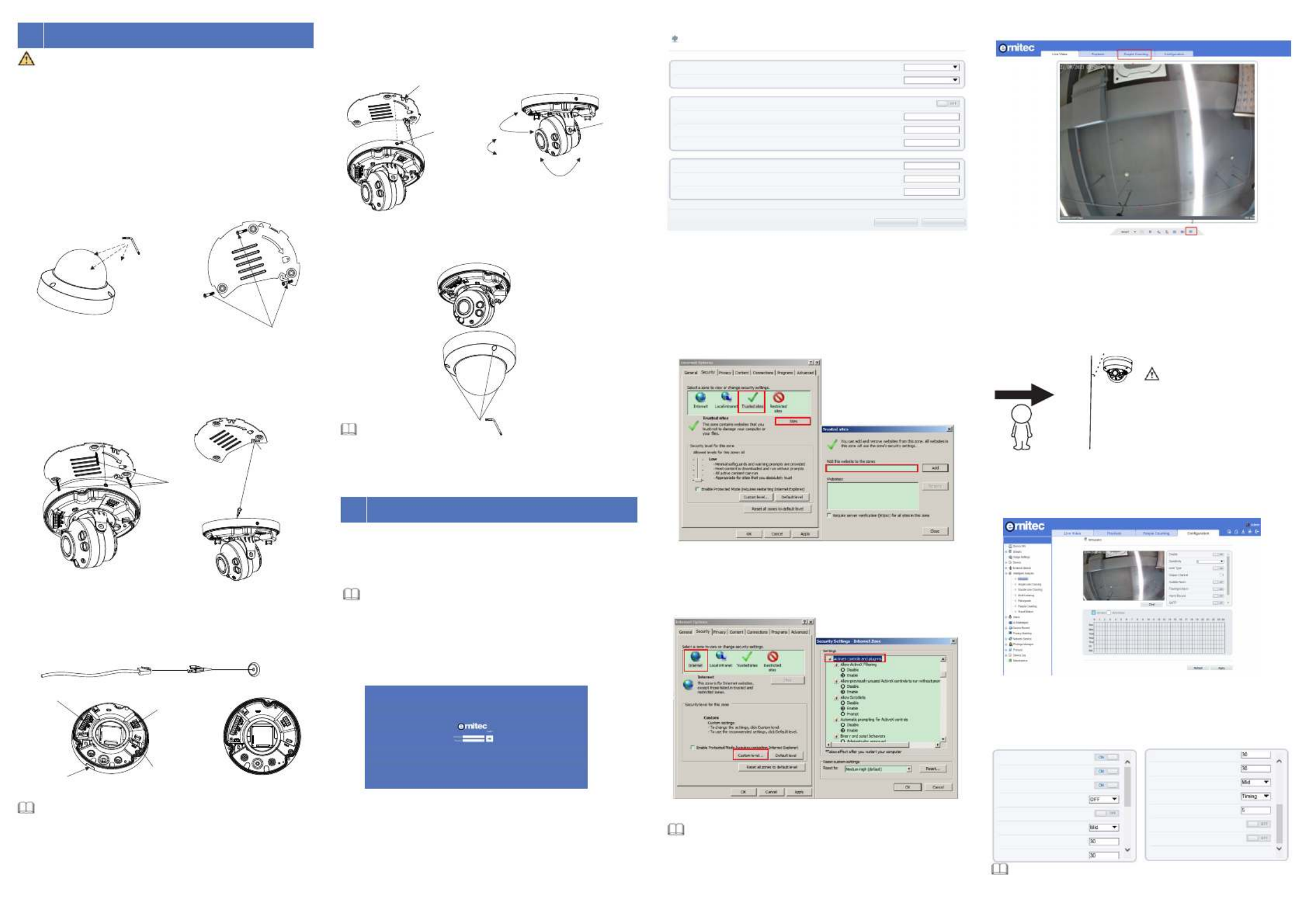
Figure 3-6 Assembling cover 4.3 Browsing Video
To ensure the real-time video can be played properly, you must perform
the following operation when you login the web for the first time:
If you can view the live video directly please ignore the steps of adding ,
trusted sites .
Figure 4 3 - Adding a trusted site
Step 2 In the Internet Explorer, choose Tool Internet Options > >
Security Customer level > , and set Download unsigned
ActiveX control and initialize and script ActiveX controls not
marked as safe for scripting under ActiveX controls and
plug-ins to Enable, as shown in figure 4-4.
Step 3 Download and install the player control as prompted.
If the repair tips are displayed when installing the control , please
ignore the prompt, and continue the installation, the close browser
during installing. Then login the page again.
Step 1 The Internet Explorer. > >Choose Tools Internet options
Security Trusted sites Sites > > , in the display dialog box, click
Add, as shown in figure 4-3.
To browse a real-time video, login the device and click Live
Video. The Live Video page is displayed, as shown in figure 4-5.
Figure 4 5 - Live Video
Figure 4 4- Configuring ActiveX control and plug-in
NOTE
4.1 Login
Step 1 Open the Internet Explorer, input the IP address of IP camera
(the default value: 192.168.0.120) in the address box, and press
Enter. The login page is displayed as shown in figure 4-1.
Step Input the user name and password.2
Step3 Click Login
NOTE
ŸThe default user name is Admin. The default password is 1234.
Ÿ It is advised to restart the device three minutes later after
modifying password to ensure modified successfully.
Ÿ User can change the system display language on the login page.
, the main page is displayed.
4.2 Modify IP address
Choose , the Configuration > Device > Local Network Local Network
page is displayed.
Input the IP address in the IP Address box and click as shown in Apply
figure 4-2.
After the IP address is set successfully, please use the new IP address
to login the Web interface.
Figure 4 2 - Local Network
Figure 4 1 - Login
Q
Q
Q
QQu
u
u
uui
i
i
iic
c
c
cck C
k C
k C
k Ck Co
o
o
oon
n
n
nnf
f
f
ffi
i
i
iig
g
g
ggu
u
u
uur
r
r
rra
a
a
aat
t
t
tti
i
i
iio
o
o
oon
n
n
nn(
(
(
((e
e
e
ee.
.
.
..g I
g I
g I
g Ig IE
E
E
EE)
)
)
))4
Step 4 Plug the network access port into interface by using the
tool, as shown in figure 3-3; The power supply of the
multi-head cable and other port to interface pass through
the rubber stopper by using screw driver or L hexagonal
wrench.
Horizontal
rotating
350°
Vertical
rotating 80°
Lens axis
rotating
350°
slotted
screw
Figure 3 -3 Installing housing
NOTE
ŸDuring adjusting ns the set the focus le , image mi ght be bl ur,
value in page in web page.Sensor > Lens control
Step 6 Connect the camera to monitor, loosen the screws of
support frame, as shown in figure 3-5. Adjust the three
axes to focus image on monitoring scenarios. Tighten the
screws to finish adjustment.
Figure 3-2 Installation
Se lf- tapp ing s cre ws
The b um p
12 V Po we r
suppl y
Netwo rk p or t
Al ar m /A udio
inter fa ce
NOTE
ŸThere are two outlet mode of cable, for the top outlet mode, user
should drill the hole at first for threading cable.
ŸThe side outlet mode that the installation sticker’s gap should
align the outlet rubber stopper.
Si de ou tl et
rub ber stop per
Se t sc r ew
Bl ock Figure 3-5 adjust lens
Step 7 Arrange the cable of camera to over-line buckle, then
assemble the dome cover with hex wrench, as shown in
figure 3-6.
hexagonal wrench
Installation Steps:
Step 1 Stick the Installation location sticker which is in accessory
package on the ceiling or wall. Drill three holes based on
the marks on the sticker. Drive the plastic anchors into the
holes.
Step 2 Use the wrench in the accessory package to unscrew the
three screws on the dome cover. The camera is opened,
as shown in figure 3-1. And use release the base panel
To avoid moisture influence, install the dome cover at least
half an hour after the camera is installed and powered on.
Step 3 Fetch three black self-tapping screws from the accessory
package. Then fix the screws to fasten the base panel of
camera on the ceiling as shown in figure 3-2.The position
of hook should be put at the appropriate place, which
should pass the bump as shown in figure 3-2.
Figure 3-1 Opening camera
The vandal dome camera can be installed in the ceiling, wall,
wall bracket or ceiling bracket. This section describes how to
install the camera in the ceiling.
WARNING
3D
D
D
DDe
e
e
eev
v
v
vvi
i
i
iic
c
c
cce I
e I
e I
e Ie In
n
n
nns
s
s
sst
t
t
tta
a
a
aal
l
l
lll
l
l
lla
a
a
aat
t
t
tti
i
i
iio
o
o
oon
n
n
nn
Pla stic
anc hor s
Local Network
Net work Card ID
IP Pro toc ol
DHC P
IP Addre ss
Sub net Mask
Def aul t Gat eway
Preferred D NS Server
Alt ernate D NS Server
MTU (12 80- 1500 )
Refresh Apply
1500
192.168.0.120
255.255.255.0
192.168.0.1
1
IPv4
ht tp :/ /19 2. 16 8. 0. 120
1 Personnel Count: User can query the data of personnel count,
through year, month, day. The statistics can be downloaded. The
data can be shown by line chart, histogram, list.
2 AI Live video: Click the icon to view the snapshots of human face
or license plate (click “Face” or “Plate” to switch ).
The bottom page will show the captured images of vehicle and
human face.
4.4 Intelligent Analysis
At Configuration Intelligent Analysis interface user can set the " > " ,
parameters of Perimeter Single Virtual Fence Double Virtual Fence , , ,
Multi Loiter Converse and Personnel Count as shown in figure 4 7 , , - .
Figure 4 7 - Intelligent Analysis
4.5 AI Multi object
At “Configuration > AI Multi object” interface, user can enable face
detection, full body detection, vehicle detection, set the other
parameters of detection, as shown in figure 4-8.
Figure 4 8 - AI Multi-object
Face Detec tion
Fullbody Detection
Veh icle Detect ion
Dis play Trac e Info
Sh ow Detec tion Area
Confid en ce Coeffic ient
Fa ce Pixel Min(3 0-300)
Bo dy Pix el Min(30-3 00 )
Bo dy Pix el Min(30-3 00 )
Veh icle Pixe l Min (30-3 00 )
Ima ge Matt ing Q u ali ty
Sn apsh ot Mo de
Uploa d I mage In terval(1 -10s)
FTP Up loa d Imag e Ma ttin g
FTP Up loa d Whole Ima ge
Alg or ith ms Libra ry Ver sio n
A
B
Pedestrian direction
15°
If user requires higher
accuracy of personnel count,
we recommend the user to
install camera and draw the
line following as figure 4-6.
Figure 4 6 - Installation of personnel count
CAU TION
NOTE
For better capture performance, it is recommended to use 6mm
focus length lens or above.
Produktspezifikationen
| Marke: | Ernitec |
| Kategorie: | Überwachungskamera |
| Modell: | 0070-08117 |
| Gewicht: | 730 g |
| Produktfarbe: | Weiß |
| Energiequelle: | PoE |
| Befestigungstyp: | Decke/Wand/Stange |
| Paketgewicht: | 1000 g |
| Gehäusematerial: | Metall |
| Brennweitenbereich: | 2.7 - 13.5 mm |
| Nachtsichtdistanz: | 40 m |
| Sensor-Typ: | CMOS |
| Infrarot-Wellenlänge: | 850 nm |
| IK-Kodex: | IK10 |
| Unterstützte Positionierung: | Innen & Außen |
Brauchst du Hilfe?
Wenn Sie Hilfe mit Ernitec 0070-08117 benötigen, stellen Sie unten eine Frage und andere Benutzer werden Ihnen antworten
Bedienungsanleitung Überwachungskamera Ernitec

4 September 2024
2 September 2024
23 August 2024
23 August 2024
23 August 2024
23 August 2024
21 August 2024
21 August 2024
21 August 2024
19 August 2024
Bedienungsanleitung Überwachungskamera
- Überwachungskamera Samsung
- Überwachungskamera Approx
- Überwachungskamera Belkin
- Überwachungskamera Sanyo
- Überwachungskamera Exibel
- Überwachungskamera Gembird
- Überwachungskamera Genius
- Überwachungskamera Hama
- Überwachungskamera LogiLink
- Überwachungskamera Logitech
- Überwachungskamera Manhattan
- Überwachungskamera Nedis
- Überwachungskamera Niceboy
- Überwachungskamera Philips
- Überwachungskamera Sony
- Überwachungskamera Trust
- Überwachungskamera Panasonic
- Überwachungskamera Clas Ohlson
- Überwachungskamera Profile
- Überwachungskamera ZyXEL
- Überwachungskamera Bosch
- Überwachungskamera Laserliner
- Überwachungskamera Buffalo
- Überwachungskamera Canon
- Überwachungskamera Velleman
- Überwachungskamera Powerfix
- Überwachungskamera Eminent
- Überwachungskamera Linksys
- Überwachungskamera Maginon
- Überwachungskamera Netgear
- Überwachungskamera Technaxx
- Überwachungskamera Alecto
- Überwachungskamera Denver
- Überwachungskamera EMOS
- Überwachungskamera Gira
- Überwachungskamera König
- Überwachungskamera MarQuant
- Überwachungskamera Renkforce
- Überwachungskamera Thomson
- Überwachungskamera Trevi
- Überwachungskamera Blaupunkt
- Überwachungskamera Schneider
- Überwachungskamera Trebs
- Überwachungskamera Pyle
- Überwachungskamera Topcom
- Überwachungskamera Pioneer
- Überwachungskamera JVC
- Überwachungskamera Motorola
- Überwachungskamera Xiaomi
- Überwachungskamera Abus
- Überwachungskamera Avidsen
- Überwachungskamera Elro
- Überwachungskamera EZVIZ
- Überwachungskamera Imou
- Überwachungskamera INSTAR
- Überwachungskamera Megasat
- Überwachungskamera Olympia
- Überwachungskamera Smartwares
- Überwachungskamera Switel
- Überwachungskamera Yale
- Überwachungskamera Ferguson
- Überwachungskamera Orion
- Überwachungskamera Gigaset
- Überwachungskamera Strong
- Überwachungskamera Toshiba
- Überwachungskamera Garmin
- Überwachungskamera Perel
- Überwachungskamera Netis
- Überwachungskamera Lindy
- Überwachungskamera Fenton
- Überwachungskamera Waeco
- Überwachungskamera Acme
- Überwachungskamera Burg Wächter
- Überwachungskamera Marmitek
- Überwachungskamera Marshall
- Überwachungskamera Honeywell
- Überwachungskamera B/R/K
- Überwachungskamera Marshall Electronics
- Überwachungskamera TRENDnet
- Überwachungskamera Targa
- Überwachungskamera First Alert
- Überwachungskamera AVerMedia
- Überwachungskamera Zebra
- Überwachungskamera TP-Link
- Überwachungskamera Flamingo
- Überwachungskamera Kodak
- Überwachungskamera Rollei
- Überwachungskamera IGet
- Überwachungskamera Adj
- Überwachungskamera Netatmo
- Überwachungskamera Duramaxx
- Überwachungskamera Ebode
- Überwachungskamera Xavax
- Überwachungskamera InFocus
- Überwachungskamera Overmax
- Überwachungskamera Monoprice
- Überwachungskamera Monacor
- Überwachungskamera JUNG
- Überwachungskamera Ednet
- Überwachungskamera AG Neovo
- Überwachungskamera Nest
- Überwachungskamera Edimax
- Überwachungskamera V-TAC
- Überwachungskamera Aritech
- Überwachungskamera Uniden
- Überwachungskamera Kogan
- Überwachungskamera Genie
- Überwachungskamera M-e
- Überwachungskamera Elmo
- Überwachungskamera Lumens
- Überwachungskamera Jablocom
- Überwachungskamera Conceptronic
- Überwachungskamera D-Link
- Überwachungskamera Eufy
- Überwachungskamera Stabo
- Überwachungskamera Friedland
- Überwachungskamera EVOLVEO
- Überwachungskamera SPC
- Überwachungskamera August
- Überwachungskamera Ring
- Überwachungskamera Digitus
- Überwachungskamera SereneLife
- Überwachungskamera Swann
- Überwachungskamera Vitek
- Überwachungskamera DataVideo
- Überwachungskamera LevelOne
- Überwachungskamera Aida
- Überwachungskamera APC
- Überwachungskamera Beafon
- Überwachungskamera Chuango
- Überwachungskamera Cisco
- Überwachungskamera Grandstream
- Überwachungskamera Delta Dore
- Überwachungskamera EVE
- Überwachungskamera Defender
- Überwachungskamera Tenda
- Überwachungskamera Swisstone
- Überwachungskamera Foscam
- Überwachungskamera Ubiquiti Networks
- Überwachungskamera Kramer
- Überwachungskamera Vaddio
- Überwachungskamera Intellinet
- Überwachungskamera Reolink
- Überwachungskamera Swan
- Überwachungskamera Hikvision
- Überwachungskamera FLIR
- Überwachungskamera Furrion
- Überwachungskamera Arlo
- Überwachungskamera Nexxt
- Überwachungskamera Planet
- Überwachungskamera EnGenius
- Überwachungskamera Dörr
- Überwachungskamera Lorex
- Überwachungskamera Ikan
- Überwachungskamera Comtrend
- Überwachungskamera Somfy
- Überwachungskamera Dahua
- Überwachungskamera Dedicated Micros
- Überwachungskamera DIO
- Überwachungskamera EasyN
- Überwachungskamera Escam
- Überwachungskamera EverFocus
- Überwachungskamera Ganz
- Überwachungskamera GeoVision
- Überwachungskamera Hombli
- Überwachungskamera Home Protector
- Überwachungskamera Iiquu
- Überwachungskamera Indexa
- Überwachungskamera Interlogix
- Überwachungskamera KlikaanKlikuit
- Überwachungskamera Kompernass
- Überwachungskamera Mr Safe
- Überwachungskamera Naxa
- Überwachungskamera Nordval
- Überwachungskamera Notifier
- Überwachungskamera Oplink
- Überwachungskamera Provision ISR
- Überwachungskamera Quantum
- Überwachungskamera Raymarine
- Überwachungskamera Revo
- Überwachungskamera SAB
- Überwachungskamera Satel
- Überwachungskamera SecurityMan
- Überwachungskamera Sinji
- Überwachungskamera SMC
- Überwachungskamera Sonic Alert
- Überwachungskamera Sricam
- Überwachungskamera Steren
- Überwachungskamera Storage Options
- Überwachungskamera Tenvis
- Überwachungskamera Hive
- Überwachungskamera Ubiquiti
- Überwachungskamera Vivotek
- Überwachungskamera Woonveilig
- Überwachungskamera Y-cam
- Überwachungskamera ACTi
- Überwachungskamera AVer
- Überwachungskamera Epcom
- Überwachungskamera ZKTeco
- Überwachungskamera AirLive
- Überwachungskamera Mobotix
- Überwachungskamera Dahua Technology
- Überwachungskamera Speco Technologies
- Überwachungskamera 3xLOGIC
- Überwachungskamera Atlantis Land
- Überwachungskamera CRUX
- Überwachungskamera Pentatech
- Überwachungskamera Summer Infant
- Überwachungskamera Illustra
- Überwachungskamera Surveon
- Überwachungskamera Avigilon
- Überwachungskamera Brilliant
- Überwachungskamera Hanwha
- Überwachungskamera Lanberg
- Überwachungskamera Verint
- Überwachungskamera Axis
- Überwachungskamera EtiamPro
- Überwachungskamera MEE Audio
- Überwachungskamera Advantech
- Überwachungskamera Chacon
- Überwachungskamera Alula
- Überwachungskamera EKO
- Überwachungskamera IOIO
- Überwachungskamera KJB Security Products
- Überwachungskamera BZBGear
- Überwachungskamera Adesso
- Überwachungskamera Brickcom
- Überwachungskamera Insteon
- Überwachungskamera Aigis
- Überwachungskamera Pelco
- Überwachungskamera ORNO
- Überwachungskamera Atlona
- Überwachungskamera Linear PRO Access
- Überwachungskamera Laxihub
- Überwachungskamera Valueline
- Überwachungskamera Aqara
- Überwachungskamera Tecno
- Überwachungskamera Lutec
- Überwachungskamera Brinno
- Überwachungskamera Night Owl
- Überwachungskamera WyreStorm
- Überwachungskamera Exacq
- Überwachungskamera Equip
- Überwachungskamera AVMATRIX
- Überwachungskamera UniView
- Überwachungskamera Alfatron
- Überwachungskamera Syscom
- Überwachungskamera BLOW
- Überwachungskamera Videotec
- Überwachungskamera DSC
- Überwachungskamera AViPAS
- Überwachungskamera Milestone Systems
- Überwachungskamera Inkovideo
- Überwachungskamera Hamlet
- Überwachungskamera Mobi
- Überwachungskamera Infortrend
- Überwachungskamera VideoComm
- Überwachungskamera Kguard
- Überwachungskamera Boyo
- Überwachungskamera HiLook
- Überwachungskamera Mach Power
- Überwachungskamera Canyon
- Überwachungskamera Digital Watchdog
- Überwachungskamera Ikegami
- Überwachungskamera Gewiss
- Überwachungskamera Weldex
- Überwachungskamera Costar
- Überwachungskamera Sentry360
- Überwachungskamera ALC
- Überwachungskamera Spyclops
- Überwachungskamera Compro
- Überwachungskamera IDIS
- Überwachungskamera I3International
- Überwachungskamera B & S Technology
- Überwachungskamera Qian
- Überwachungskamera Accsoon
- Überwachungskamera Control4
- Überwachungskamera Petcube
- Überwachungskamera Apeman
- Überwachungskamera ATN
- Überwachungskamera IC Intracom
- Überwachungskamera POSline
- Überwachungskamera Watec
- Überwachungskamera ETiger
- Überwachungskamera Videcon
- Überwachungskamera BirdDog
- Überwachungskamera Topica
- Überwachungskamera Rostra
- Überwachungskamera Caddx
- Überwachungskamera Whistler
- Überwachungskamera ClearView
- Überwachungskamera Beseye
- Überwachungskamera IMILAB
- Überwachungskamera CNB Technology
- Überwachungskamera Tapo
- Überwachungskamera Securetech
- Überwachungskamera NetMedia
- Überwachungskamera Nivian
- Überwachungskamera Guardzilla
- Überwachungskamera Blink
- Überwachungskamera Zavio
- Überwachungskamera Campark
- Überwachungskamera IPX
- Überwachungskamera Annke
- Überwachungskamera AVTech
- Überwachungskamera Vimtag
- Überwachungskamera Security Labs
- Überwachungskamera Seneca
- Überwachungskamera Vosker
- Überwachungskamera Owltron
- Überwachungskamera Enabot
- Überwachungskamera Luis Energy
- Überwachungskamera Sir Gawain
- Überwachungskamera VisorTech
- Überwachungskamera Milesight
- Überwachungskamera GVI Security
- Überwachungskamera Conbrov
- Überwachungskamera HuddleCamHD
- Überwachungskamera Setti+
- Überwachungskamera BIRDFY
- Überwachungskamera I-PRO
- Überwachungskamera DVDO
- Überwachungskamera TCP
Neueste Bedienungsanleitung für -Kategorien-
15 Oktober 2024

15 Oktober 2024
14 Oktober 2024
14 Oktober 2024

13 Oktober 2024
13 Oktober 2024
13 Oktober 2024
11 Oktober 2024
11 Oktober 2024
11 Oktober 2024