Dimplex ECSd300ST-580 Bedienungsanleitung
Dimplex
Nicht kategorisiert
ECSd300ST-580
Lesen Sie kostenlos die 📖 deutsche Bedienungsanleitung für Dimplex ECSd300ST-580 (60 Seiten) in der Kategorie Nicht kategorisiert. Dieser Bedienungsanleitung war für 12 Personen hilfreich und wurde von 2 Benutzern mit durchschnittlich 4.5 Sternen bewertet
Seite 1/60
Important - This manual must be left with the user after Installation!
EC-Eau Cylinder Range
Installation and User Instructions
Solar Direct, Solar Indirect and
Solar Heat Pump Cylinders
Up to 300L
Installation and User Instructions R01128-8 09/15
Page 2
Dimplex is a licensed member of the Benchmark Scheme which aims to improve
the standards of installation and commissioning of domestic heating and hot
water systems in the UK and to encourage regular servicing to optimise safety,
efficiency and performance.
Benchmark places responsibilities on both manufacturers and installers. The
purpose is to ensure that customers are provided with the correct equipment for
their needs, that it is installed, commissioned and serviced in accordance with
the manufacturer’s instructions by competent persons and that it meets the
requirements of the appropriate Building Regulations. The Benchmark Checklist
can be used to demonstrate compliance with Building Regulations and should be
provided to the customer for future reference.
Installers are required to carry out installation, commissioning and servicing work
in accordance with the Benchmark Code of Practice which is available from the
Heating and Hot Water Industry Council who manage and promote the Scheme.
Visit www.centralheating.co.uk for more information.
The HWA Charter requires that all members adhere to the following:
supply fit for purpose products clearly and honestly described
supply products that meet, or exceed appropriate standards and
building and water regulations
provide pre and post sales technical support
provide clear and concise warranty details to customers
For further information on the HWA Charter Membership, please refer to the
HWA website www.hotwater.org.uk’
Installation and User Instructions R01128-8 09/15
Page 3
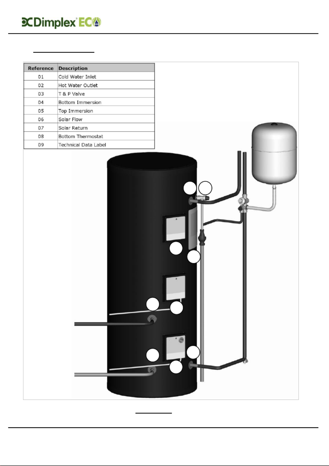
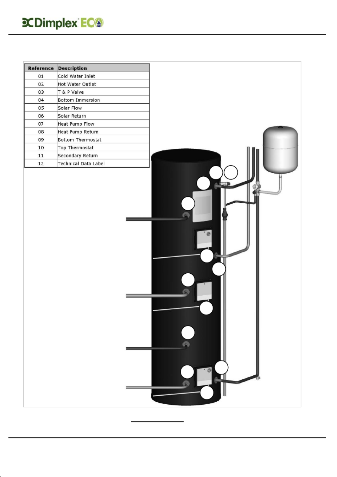
Overall View
0 Overall View
Figure 1: Overall view of Cylinder Installation process Solar Direct
02
03
09
01
07
04
08
06
05
Installation and User Instructions R01128-8 09/15
Page 4
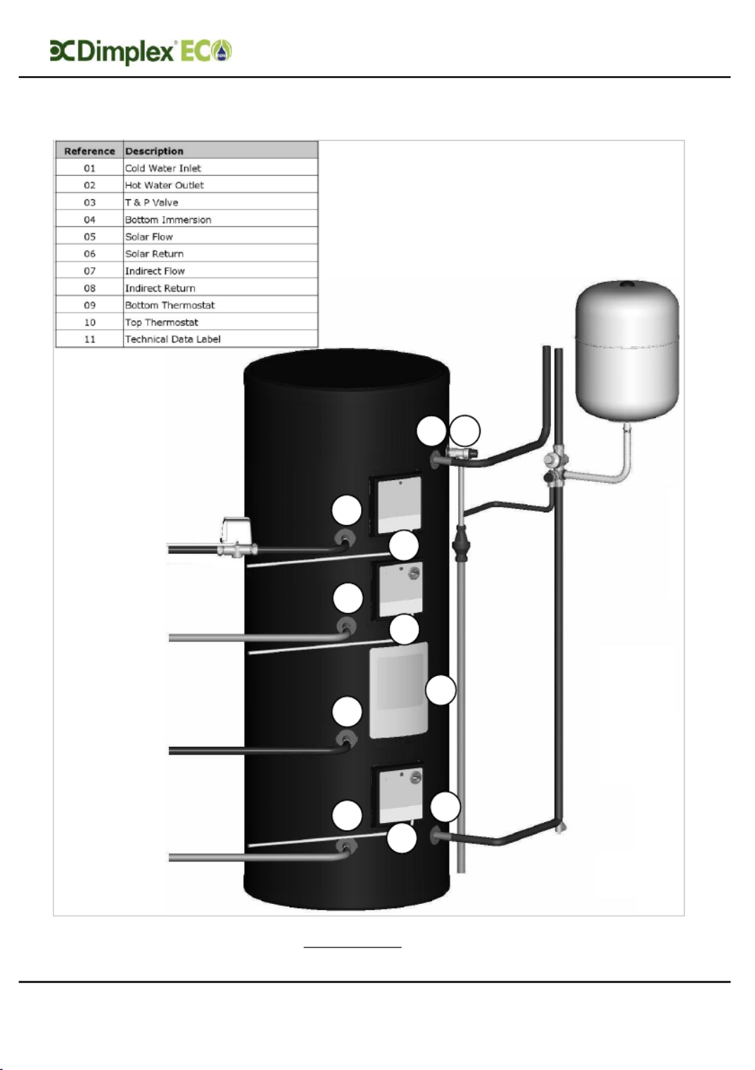
Overall View
Figure 2: Overall view of Cylinder Installation process Solar Indirect
02
03
11
01
06
04
09
05
10
07
08
Installation and User Instructions R01128-8 09/15
Page 5
Overall View
Figure 3: Overall view of Cylinder Installation processSolar Heat Pump
02
03
11
01
06
04
09
05
10
07
08
12

Installation and User Instructions R01128-8 09/15
Page 7
Contents
9.1 C YLINDER HEAT EXCHANGER PRESSURE DROP ..................................................... 48
10 USER INSTRUCTIONS ................................................................................ 50
10.1 G ENERAL ............................................................................................. 50
10.2 O PERATION .......................................................................................... 51
10.2.1 Water temperature direct electric heating ........................................ 51
10.2.2 Water temperature auxiliary heating ............................................... 52
10.3 M AINTENANCE ....................................................................................... 52
10.4 T ROUBLESHOOTING................................................................................. 53
Installation and User Instructions R01128-8 09/15
Page 9
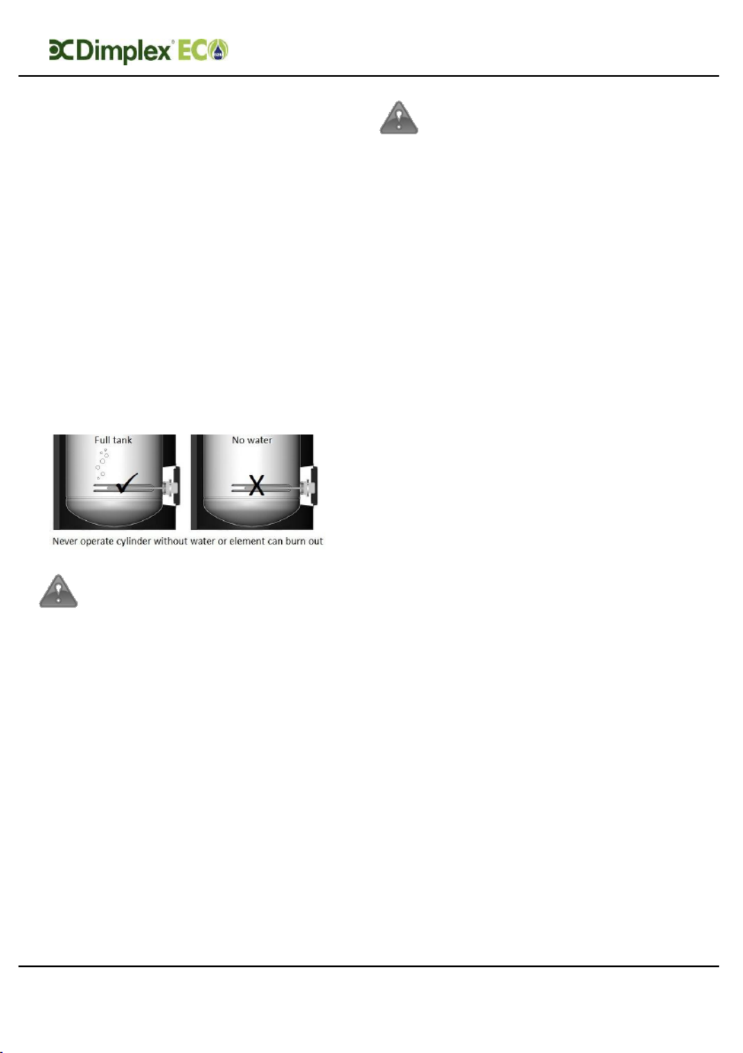
Important Information
when working inside
immersion housing.
Note: The cylinder
must be filled with
water before switching
on the immersion
heater. Failure to do so
will damage the
element and void any
guarantee on the
product.
The maintenance of
this appliance must
be carried out by a
suitably qualified
person only. It is
recommended to
maintain the unit on
an annual basis.
Isolate all electrical
supplies from the
unit before
commencing work.
Danger of electrical
shock!
CLEANING
INSTRUCTIONS:
Clean outer
cladding of cylinder
with a soft cloth
dampened with
warm water only.
Do not use abrasive
or aggressive
cleaning materials,
such as alcohol or
petroleum based
solvents, as this
may damage the
surface of the
product.
Temperature setting: A
high level cutout is
fitted to the product for
each heat source. This
should never activate
under normal
operation. The
maximum possible
cylinder temperature
attainable by the heat
pump is 65°C as set on
the User Interface. The
back-up immersion
heater can produce up
to 72°C at its maximum
setting, i.e 5. For

Installation and User Instructions R01128-8 09/15
Page 10
Important Information
convenience the
immersion heater is
preset to produce
60°C.
If an electronic copy of
this manual should be
required, please contact
the manufacturer at the
address at the back of this
manual.
Note: This appliance is
intended to be
permanently
connected to the water
mains and not
connected by a hose-
set.
Dimplex cannot take
responsibility for ensuring
safe operation of the
appliance outside of the
scope of intended use.ly

Installation and User Instructions R01128-8 09/15
Page 11
Important Information
2 Introduction
Thank you for choosing a Dimplex
product. The EC-Eau solar cylinders are
specified with large, high surface area
heat exchangers, specifically sized to
match the requirements of Dimplex
solar systems. They boast 60mm of
low GWP insulation foam, together with
100% recyclable stainless steel inner
components and a sleek black, hard
wearing outer shell manufactured from
completely recycled materials. For
more detailed information on product
features, please see the Technical Data
section in this manual.
NOTE: This product has been designed
specifically for the purpose of
delivering heated, domestic and
sanitary hot water as part of a
pressurised water heating system. The
package is provided with fittings that
comply with Section G3 of Building
Regulations.
WARNING: Dimplex cannot take
responsibility for ensuring safe
operation of the appliance outside
of the scope of intended use.
Installation and User Instructions R01128-8 09/15
Page 12
Important Information
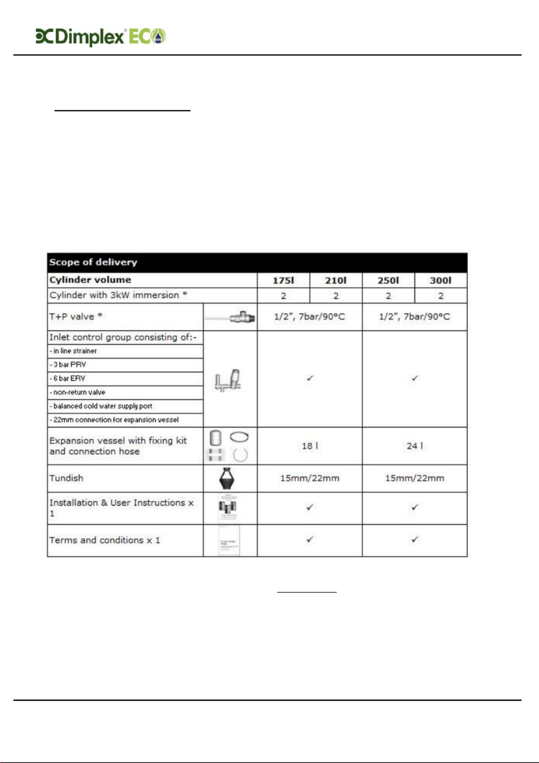
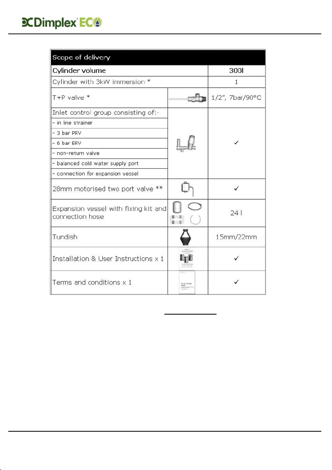
3 Scope of delivery
Please ensure you check the scope of
delivery below before signing any
delivery documentation. Claims for
missing or damaged parts after signing
for the delivery will not be accepted
.
Table 1: Scope of Delivery for CylindersSolar Direct
* These items are supplied factory fitted
Installation and User Instructions R01128-8 09/15
Page 13
Scope of Delivery
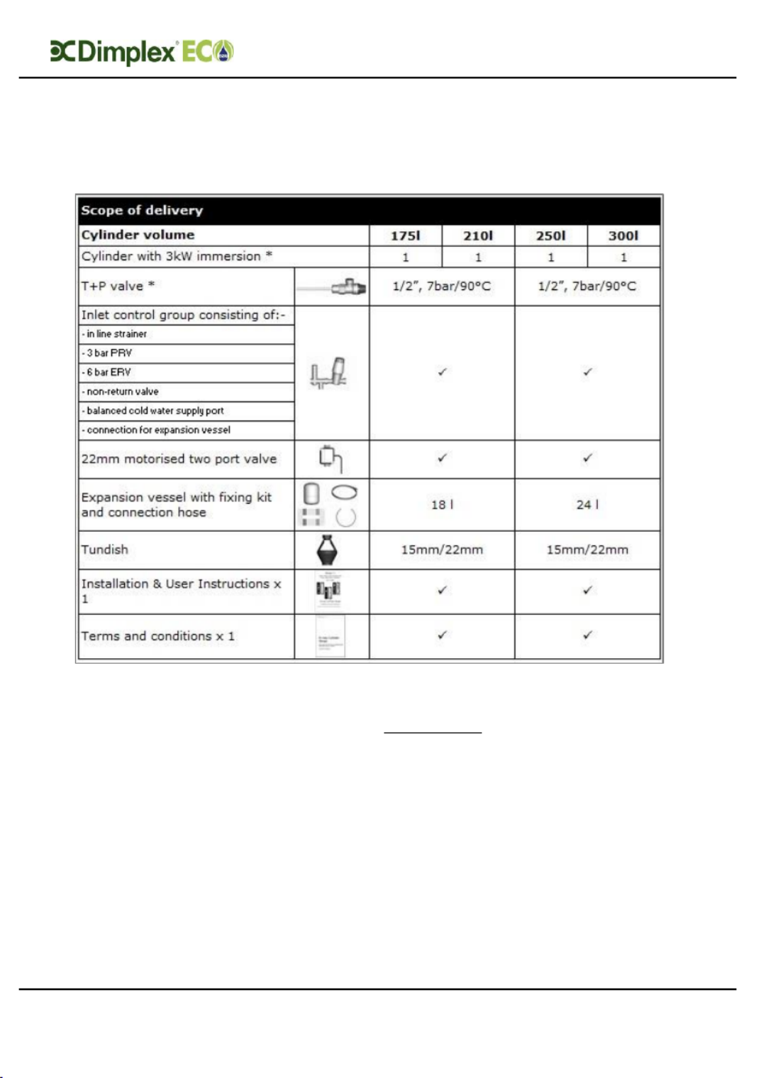
Table 2: Scope of Delivery for CylindersSolar Indirect
* These items are supplied factory fitted
Installation and User Instructions R01128-8 09/15
Page 14
Scope of Delivery
Table 3: Scope of Delivery for Cylinder Solar Heat Pump
* These items are supplied factory fitted
** Only part of the scope of delivery when not supplied as a Dimplex Heat Pump
package

Installation and User Instructions R01128-8 09/15
Page 15
Pre-Installation
4 Pre-Installation
Advice
Please read the following section
carefully before commencing
installation. If in any doubt, please call
the appropriate help desk.
Disregarding the instructions given in
this manual in its entirety and any
relevant regulations, standards and
codes of practice will void the
guarantee of this product.
Handling depending on the size of –
the unit and access to its installation
location, consideration must be given
to the handling of the unit. Please note
that handling, installation and use of
this product is subject to the Health
and Safety at Work Act.
If the unit is not installed immediately,
it should remain in its protective
packaging with all pipe protectors/end
caps applied to prevent damage and
dirt deposit inside the cylinder and the
coils.
Pipe work the pipe runs should be –
executed as short as possible, unused
pipe work should be removed and all
remaining pipe work should be lagged
in accordance with regulatory
requirements to prevent heat loss and
the formation of condensation.
Taps and fittings all taps and –
fittings incorporated in the unvented
system should have a rated operating
pressure of 0.6 MPa (6 bar) or above.
4.1 Risk assessment
The compilation of a risk assessment is
strongly recommended before
installing the product. The following
areas require particular consideration
in addition to the information required
by the Health and Safety at Work Act.
- scalding: where appropriate or
required by law a thermostatic
mixing valve is to be fitted to the hot
water outlet of the cylinder (see also
water borne organisms).
- explosion: the unit is fully equipped
with all relevant safety equipment to
comply with current regulations. The
correct design and function has been
verified by independent third party
testing. The correct application
thereof is the responsibility of the
competent installer.
- water borne organisms (i.e.
Legionella): if applicable a risk
assessment should be carried out
following the recommendations
outlined in the Approved Code of
Practice L8.
- the user preference must be
considered when commissioning the
system, in particular when adjusting
the solar and auxiliary system
temperature and timer settings.
4.2 Siting considerations
When choosing a suitable location for
the cylinder the following aspects
should be considered:
- structural integrity
- access for installation, operation,
maintenance and replacement
- routing of discharge pipe work
- access to water mains supply, hot
and cold water distribution pipe work
- access to suitable electricity supply
- location in relation to remaining
system components such as
auxiliary and solar heating system
Installation and User Instructions R01128-8 09/15
Page 16
Pre-Installation
- frost protection
The solar cylinder range designed to is
be floor standing, vertically mounted,
indoors and in a frost free
environment. The cylinder may be
located on any flat and level surface,
provided it is sufficiently robust to
support the weight of the cylinder
when full of water (please see technical
data) and suitably accessible for
replacement/maintenance without
specialist tools or lifting equipment as
this will void the warranty conditions.
The position and orientation of the
cylinder should be such that easy
access is provided for servicing the
controls. A minimum distance of
400mm in front of the immersion is
recommended, to allow the
replacement of the immersion heater
should the need arise. When installing
the cylinder all labels should be clearly
visible and ensure that no pipework
hinders any work to be carried out on
the various cylinder components.
Particular care must be taken when
placing the cylinder in a garage or
outbuilding. All exposed pipe work
must be correctly insulated to avoid
frost damage.
CLEANING INSTRUCTIONS:
Clean outer cladding of
cylinder with a soft cloth
dampened with warm water
only. Do not use abrasive or
aggressive cleaning
materials, such as alcohol or
petroleum based solvents, as
this may damage the surface
of the product.
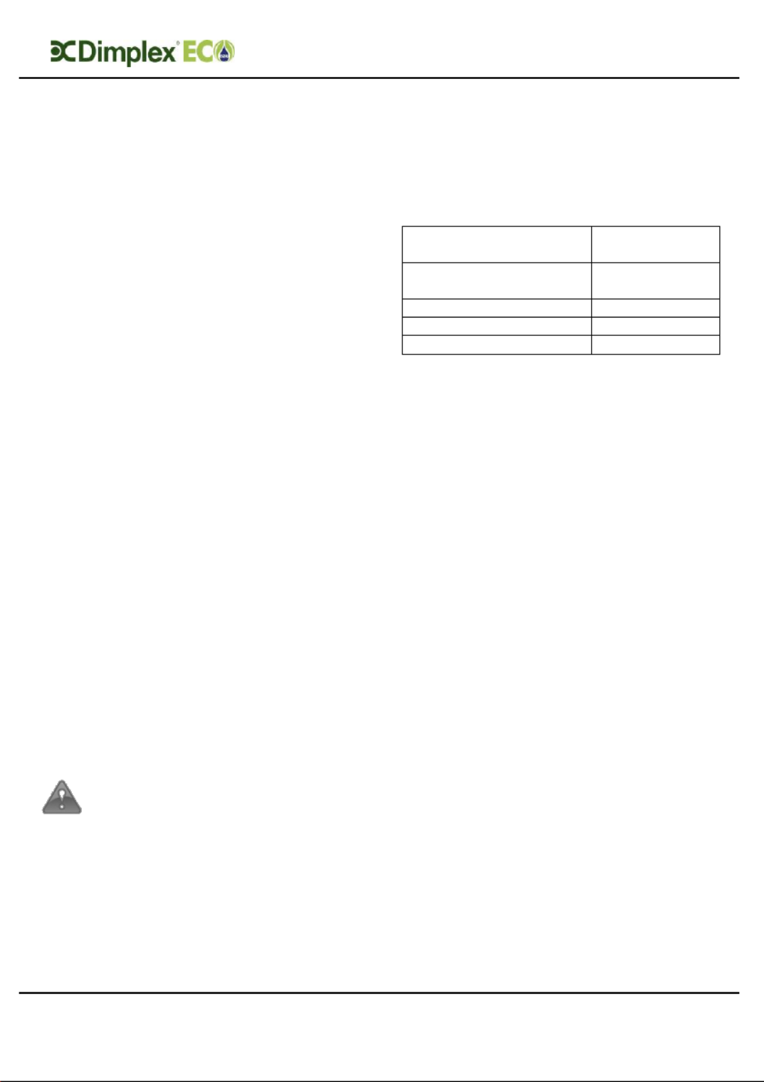
4.3 Cold water supply
For satisfactory and safe performance
of the unvented cylinder the water
supply must meet the following
criteria:
Minimum dynamic
pressure
150 kPa
(1.5 bar)
Maximum inlet supply
pressure
1200 kPa
(12 bar)
Minimum flow rate
15 l/min
Max. chlorine content
250mg/L
Max. water hardness
200mg/L
The following instructions have to be
followed when installing the cold water
mains supply to the cylinder:
- The cold water supply to the cylinder
must come directly from the cold
water mains after the mains stop
valve to the property.
- The cold water inlet pipe work should
have at least an inside diameter of
19mm and should meet the
requirements of the water
regulations for the supply of
wholesome water.

Installation and User Instructions R01128-8 09/15
Page 17
Pre-Installation
Dimplex recommend an annual
maintenance inspection carried out is
on the domestic hot water cylinder. In
hard water areas this should include
inspection of the heat exchanger and
immersion heater, [above 120ppm or
120mg/l]. A local water treatment
company should be able to offer free
water quality testing. The heating
elements may require periodic de-
scaling. The installer should do this as
part of a maintenance agreement.
If required, precautions can be taken
to minimise effects of water hardness,
i.e. installation of water conditioner or
water softener. These devices should
be installed in hard water areas where
high water storage temperatures are
required, i.e. greater than 60°C
storage temperatures, particularly
when water hardness exceeds
200ppm. Should the water cylinder
require de-scaling, this must be
performed by a qualified technician.
4.4 Building regulation G3
Discharge
requirements
As part of the requirements of Building
Regulation G3 any discharge from an
unvented system should be conveyed
to where it is visible, but will not cause
danger to persons in or about the
building. The tundish and the discharge
pipes should be fitted in accordance
with the requirements of Building
Regulation approved document G3,
(England and Wales), Part P of
Northern Ireland and Standard 4.9 of
Scotland.
Installation and User Instructions R01128-8 09/15
Page 19
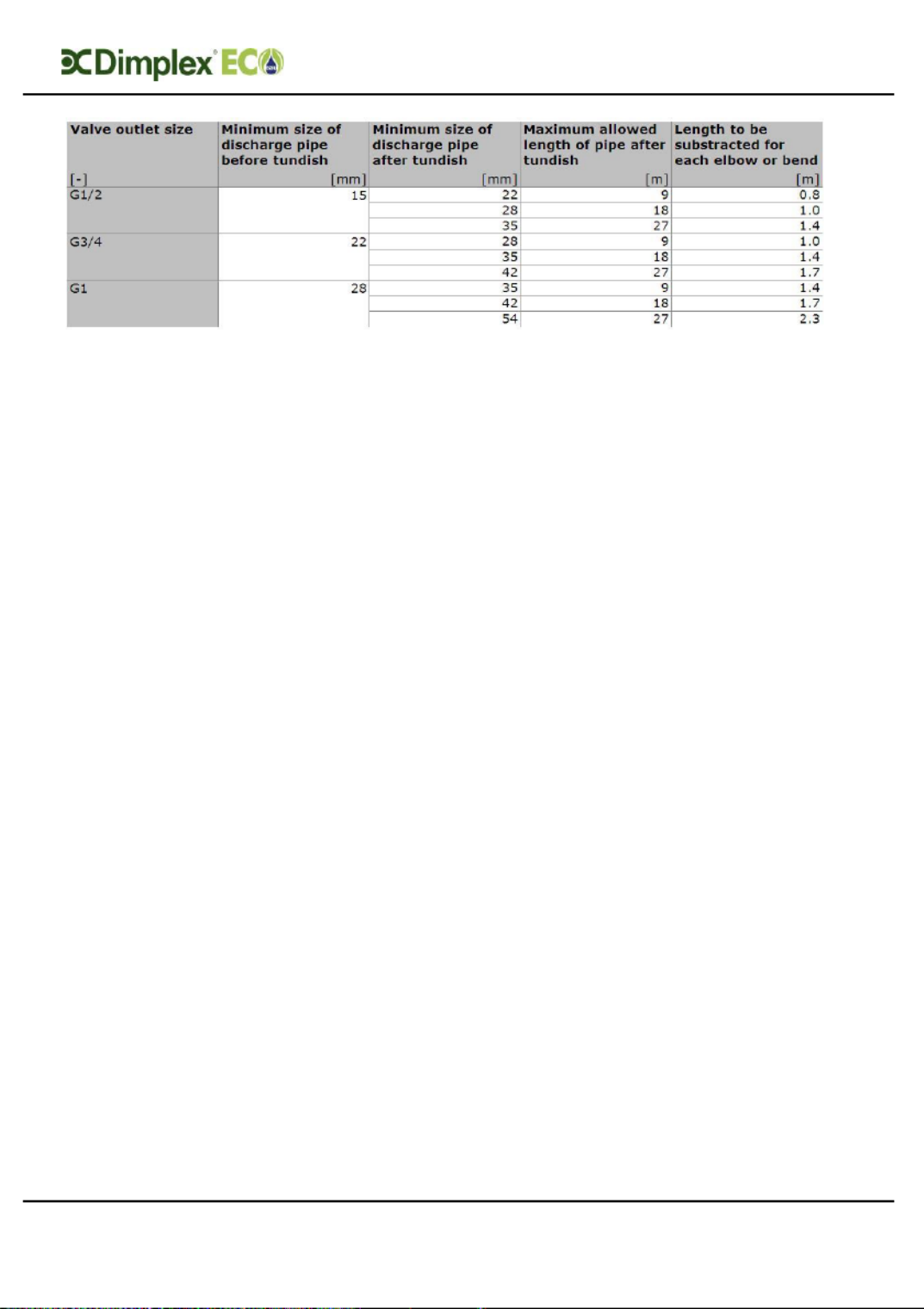
Pre-Installation
Table 4 : Sizing of copper discharge pipe “D2” for common temperature relief valve outlet sizes
4.4.2 Worked example
This example is for a G½ temperature
relief valve with a discharge pipe (D2)
(as fitted on 125 to 300L cylinders)
having 4 No. 22mm elbows and length
of 7m from the tundish to the point of
discharge.
From Table 4, the maximum resistance
allowed for a straight length of 22mm
copper discharge pipe
(D2) from a G½ temperature relief
valve is 9.0m. Subtract the resistance
for 4 No. 22mm elbows at 0.8m each
= 3.2m.
Therefore the maximum permitted
length
equates to 5.8m, which is less than the
actual length of 7m, therefore calculate
the next largest size.
Maximum resistance allowed for a
straight length of 28mm copper
discharge pipe (D2) from a G½
temperature relief valve is: 18m
Subtract the resistance for 4 No. 28mm
elbows at 1.0m each = 4m
Therefore the maximum permitted
length equates to 14m.
As the actual length is 7m, a 28mm
(D2) copper pipe will be satisfactory.

Pre-Installation
Installation and User Instructions R01128-8 09/15
Page 20
- Where a single common discharge
pipe serves more than one system,
it should be at least one pipe size
larger than the largest individual
discharge pipe (D2) to be connected.
- The discharge pipe should not be
connected to a soil discharge stack
unless the soil discharge stack is
capable of safely withstanding
temperatures of the water
discharged, in which case, it should:
- contain a mechanical seal, which
allows water into the branch pipe
without allowing foul air from the
drain to be ventilated through the
tundish.
- there should be a separate branch
pipe with no sanitary appliances
connected to it.
- if plastic pipes are used as branch
pipes carrying discharge from a
safety device, they should be
either polybutalene (PB) or cross-
linked polyethylene (PE- X)
complying with national
standards.
- be continuously marked with a
warning that no sanitary
appliances should be connected to
the pipe.
4.4.3 Termination of
discharge pipe
- “The discharge pipe (D2) from the
tundish should terminate in a safe
place where there is no risk to
persons in the vicinity of the
discharge.”
- Examples of acceptable discharge
arrangements are:
- “to a trapped gully with the end of
the pipe below a fixed grating and
above the water seal;
- downward discharges at low level;
i.e. up to 100mm above external
surfaces such as car parks, hard
standings, grassed areas etc. are
acceptable providing that a wire
cage or similar guard is positioned to
prevent contact, whilst maintaining
visibility; and ,
- discharges at high level: e.g. into a
metal hopper and metal downpipe
with the end of the discharge pipe
clearly visible or onto a roof capable
of withstanding high temperature
discharges of water and 3m from any
plastic guttering system that would
collect such discharges.”
Note: As the discharge would
consist of high temperature water
and steam, asphalt, roofing felt
and non-metallic rainwater goods
may be damaged by such
discharges.
Installation and User Instructions R01128-8 09/15
Page 22
Installation
It is important to check the
pre-charge pressure of the
expansion vessel membrane
before filling the cylinder. The
pre-charge should be greater
than or equal to 3bar.
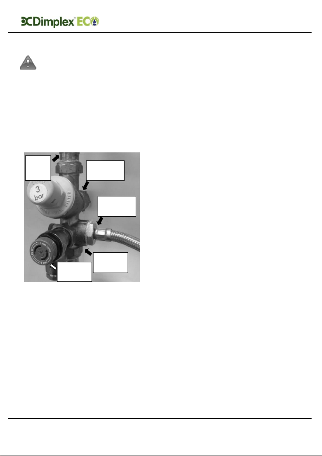
Note: The expansion vessel must
be installed to the side of the
expansion relief valve on the inlet
group. To do this the blanking plug
must be removed and the
expansion vessel connected, as
shown in Figure 6.
Figure 6: Detail showing the connection of
the expansion vessel to the inlet group
5.1.4 Balanced cold water
supply
If balanced cold water supply is
required a connection can be taken
from the bottom of the inlet group.
5.1.5 Drain valve
It is also recommended to install a
drain valve (not supplied) in the lowest
point of the cold water feed to the
cylinder. This allows the cylinder to be
drained in a controlled manner should
this become necessary.
5.2 Hot Water Outlet
The hot water pipe work is to be
directly connected to the hot water
outlet connection on the cylinder, see
Figure 1.
5.2.1 Thermostatic mixing
valve
A thermostatic mixing valve may be
required to limit the outlet
temperature. In this case, the valve
should be installed following the
manufacturer’s instructions, ensuring
none of the safety equipment has been
isolated, (i.e. make sure the
connection to the thermostatic mixing
valve is taken after the safety
equipment of the inlet group).
5.2.2 Pipe insulation
It is recommended to insulate the hot
water pipe work from the cylinder to
the outlets, to reduce the energy
requirements for providing hot water.
It is also recommended to insulate all
other exposed pipework, such as the
T&P to the tundish, the coil flow and
return and the cold water inlet pipes.
5.3 Discharge pipes from
safety devices
5.3.1 Discharge pipe D1
- The temperature and pressure relief
valve must be discharged directly or
by way of a manifold via a short
length of metal pipe (D1) into a
tundish; and the discharge pipe must
be installed in a continuously
downward direction and in a frost
free environment. Water may drip
Expansion
Vessel
Connection
Balanced
Cold Water
Supply
Expansion
Relief
Valve
Cold
Water to
Cylinder
Cold
Water
from
Mains

Installation and User Instructions R01128-8 09/15
Page 23
Installation
from the discharge pipe of the
pressure relief device and this pipe
must be left open to the atmosphere.
- The diameter of discharge pipe (D1)
should not be less than the nominal
outlet size of the safety device, e.g.
temperature relief valve.
- Where a manifold is used it should be
sized to accept and discharge the
total discharge from all the D1
discharge pipes connected to it.
- The discharge pipe work from the
expansion relief valve must be
installed constantly falling to an open
point of discharge. It is
recommended to combine it with the
discharge of the temperature and
pressure relief valve.
Note: The T&P valve is pre-sealed
and if moved the seal will be
broken, should this occur, it will
need to be resealed with an
appropriate sealant (Dimplex part
number R00836-1).
5.3.2 Discharge pipe D2
For a detailed description of the
discharge pipework D2 see chapter
4.4.1.
5.3.3 Tundish
- The tundish should be vertical,
located in the same space as the
unvented hot water storage system
and be fitted as close as possible to,
and lower than, the safety device,
with no more than 600mm of pipe
between the valve outlet and the
tundish (see Figure 4 ).
- Discharge should be visible at the
tundish, where discharges may not
be apparent, e.g. in dwellings
occupied by people with impaired
vision or mobility, consideration
should be given to the installation of
a suitable safety device to warn
when discharge takes place, e.g.
electronically operated.
Note: To comply with the Water
Supply (Water Fittings)
Regulations, the tundish should
incorporate a suitable air gap.
It is important that the tundish
is positioned away from any
electrical components.

Installat ion and User Instructions R01128 -8 09/15
Page 25
Installation
5.5 Solar coil connections
If the flow connection is the highest
point in the solar loop and if the system
was not commissioned using a flush
and fill pump, an adequate device for
de-aeration must be installed.
For ease of maintenance it is
recommended to install a drain valve
at the return connection of the solar
coil. Compression fittings should be
used to complete this part of the
installation.
Note: If the cylinder is located
higher than the solar collector
array, a two port valve has to be
installed and wired accordingly.
5.6 Auxiliary coil
connections
If the flow connection is the highest
point in the auxiliary heating loop an
adequate device for de-aeration must
be installed.
For ease of maintenance it is
recommended to install a drain valve
at the return connection of the
auxiliary heating coil, if this is the
lowest point in the auxiliary heating
loop.
It is recommended that the fittings
used to connect to the cylinder are
suitable for stainless steel, the flow and
return should use 28mm compression
fittings. Not all push fit fittings can be
used – please check with your supplier.
When using compression fittings,
ensure that the connection is not over-
tightened.
Installat ion and User Instructions R01128 -8 09/15
Page 26
Installation
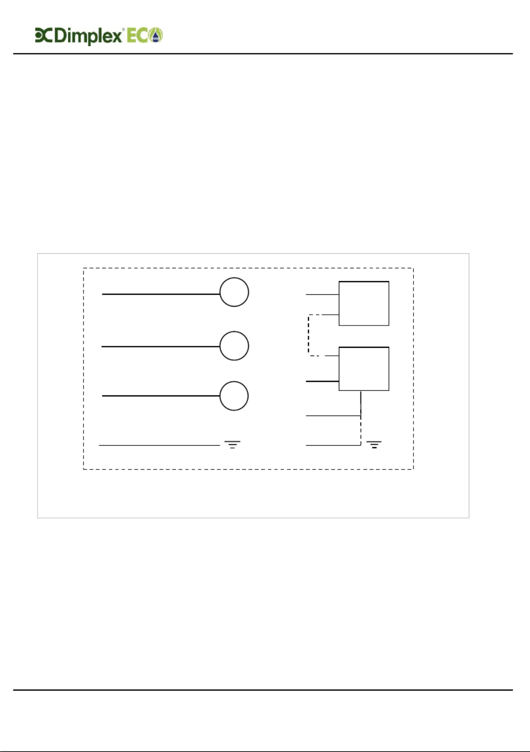
5.7 Thermostat connection
The solar circulation pump and the
auxiliary heating system can be wired
to the cylinder in various ways as
described by the chosen supplier.
To conform to building regulations, it is
imperative that any heat generator
connected to the cylinder is installed
through the correct twin thermostat,
which is factory fitted to the cylinder.
The two port valve supplied with the
solar indirect cylinder is to be installed
by default into the auxiliary heating
loop. If the cylinder is located higher
than the solar collector array, a two
port valve has to be installed in the
solar loop and wired accordingly.
Figure 8: Thermostat Wiring Schematic
T
T
T
NOTE: T1 and T2 must be connected. T3 can replace T2 only when
a normally open configuration is required.
To solar pump/
two port valve
From control unit
Temp
control
stat
High
temp cut
out stat
2
1
1
2
3
T4
Earth
Installat ion and User Instructions R01128 -8 09/15
Page 27
Installation
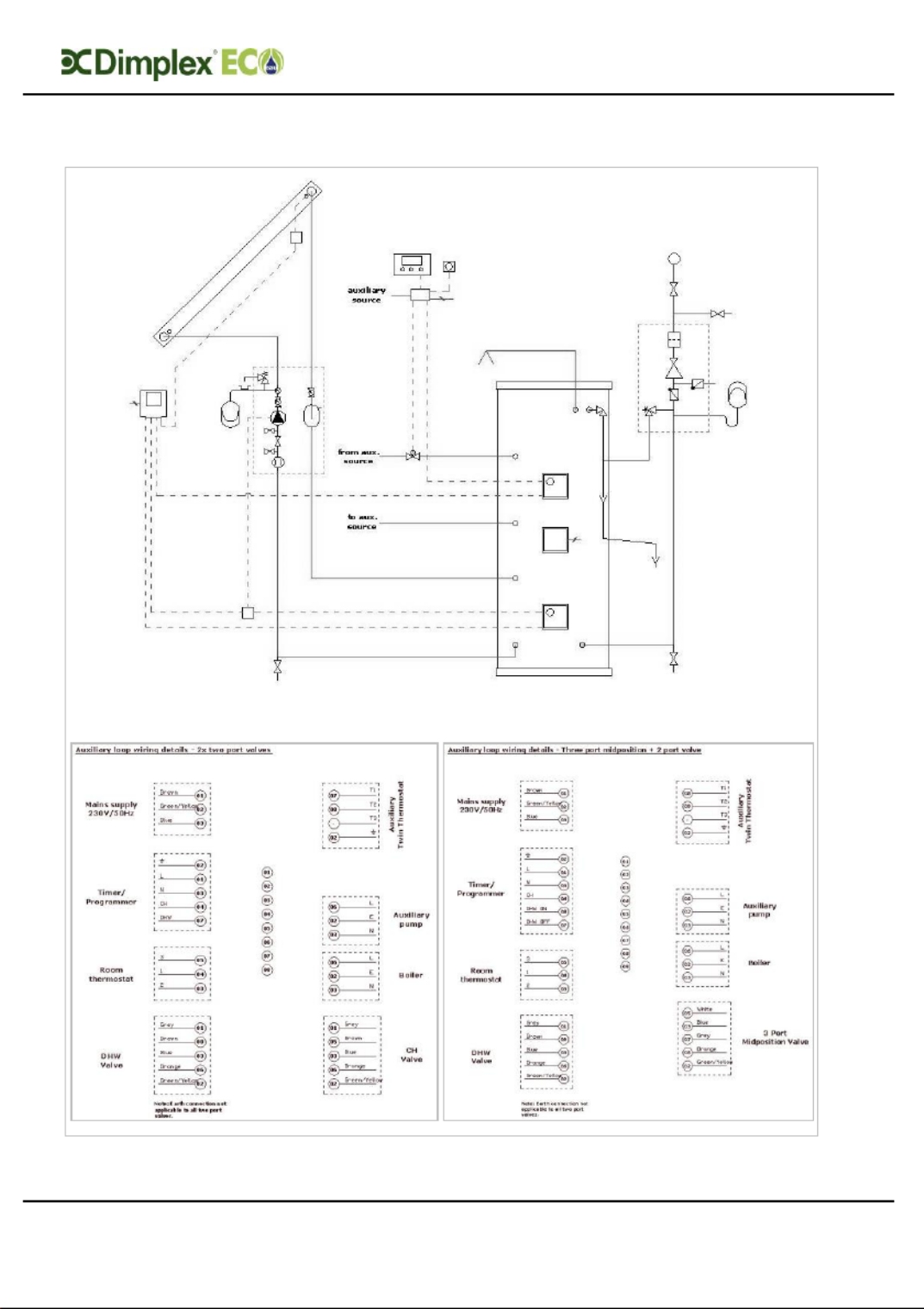
5.7.1 Auxiliary loop wiring schematic (indirect cylinder only)
Figure 9 Wiring schematic auxiliary loop :
Installat ion and User Instructions R01128 -8 09/15
Page 28
Installation
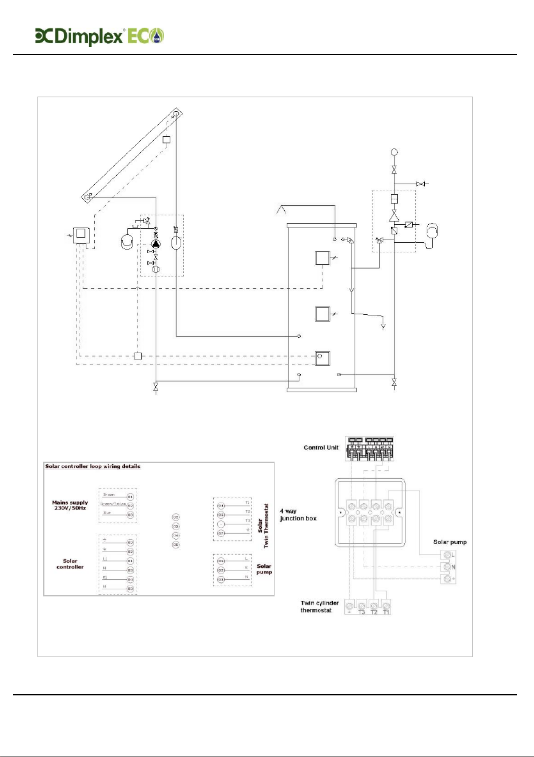
5.7.2 Solar loop wiring schematic (direct and indirect cylinders)
Figure : Wiring schematic solar loop 10
Installat ion and User Instructions R01128 -8 09/15
Page 29
Installation
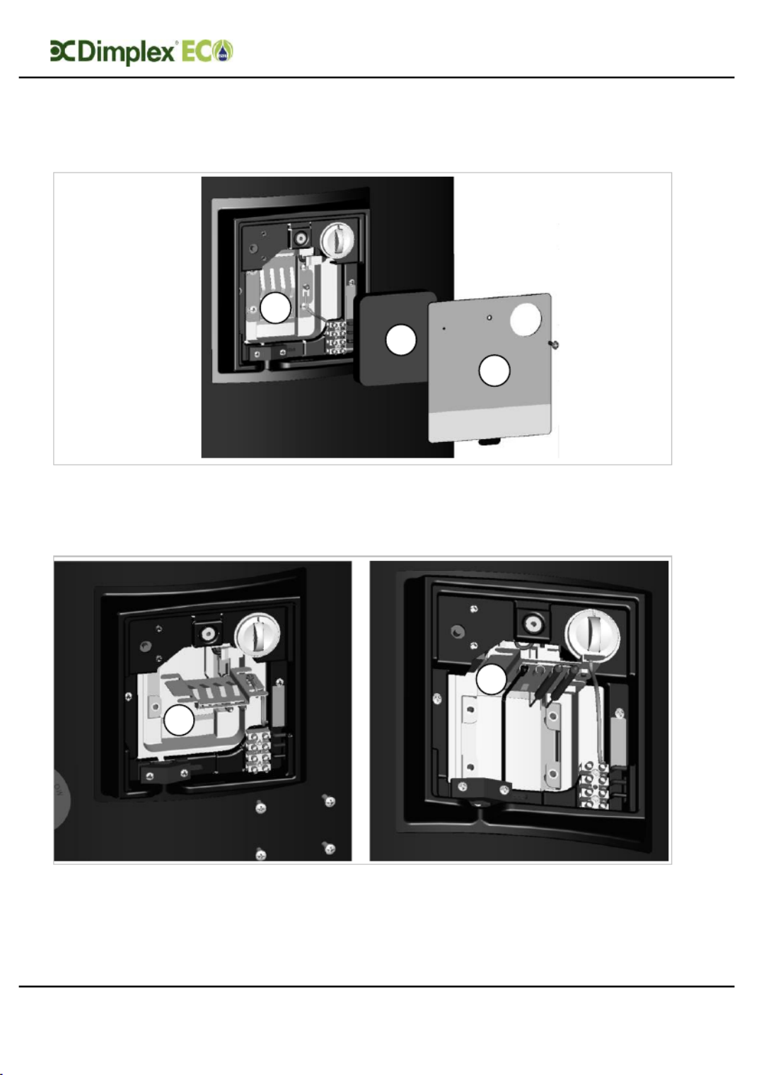
5.7.3 Solar sensor connection
5.7.3.1 Solar Sensor Connection Thermostat Housing (direct x 1, indirect x 2)
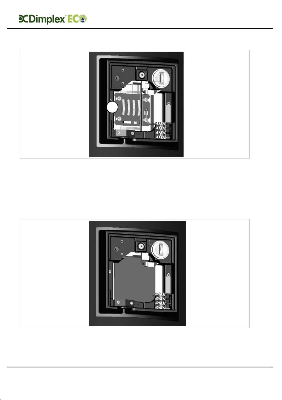
Step 1: Access the sensor mounting plate. To do this remove the Dual Cut Out cover
plate (A) by removing the fixing screw and insulation foam (B) to access the sensor
mounting plate (C). Remove the M5 fixing screws in the four corners of the plate.
Step 2: Orientate the sensor mounting plate to allow access to the phials (four clips in
the centre of the sensor mounting plate .) Be careful not to kink the capillaries that
connect the thermostat bulbs. The sensor mounting plate will have two vacant slots for
additional sensors (D). Slide the solar sensor into place as shown (E).
A
B
C
D
E
Installat ion and User Instructions R01128 -8 09/15
Page 30
Installation
Step 3: Move the sensor mounting plate back into its fixing position. Be careful not to
kink the capillaries that connect the thermostat bulbs. Fit the four M5 fixing screws into
the cylinder bracket (F). Tighten the screws until the thermostat bulbs and heat pump
sensor are held firmly against the wall of the inner cylinder.
Note: there should be no movement in the phials that are used to hold the bulbs and
sensor. Care should be taken not to overtighten the screws.
Step 4: Replace the insulating foam over the sensor mounting plate.
F
Produktspezifikationen
| Marke: | Dimplex |
| Kategorie: | Nicht kategorisiert |
| Modell: | ECSd300ST-580 |
Brauchst du Hilfe?
Wenn Sie Hilfe mit Dimplex ECSd300ST-580 benötigen, stellen Sie unten eine Frage und andere Benutzer werden Ihnen antworten
Bedienungsanleitung Nicht kategorisiert Dimplex

30 September 2024
27 September 2024
18 September 2024
12 September 2024
1 September 2024
1 September 2024
31 August 2024
31 August 2024
27 August 2024
19 August 2024
Bedienungsanleitung Nicht kategorisiert
- Nicht kategorisiert Nautilus
- Nicht kategorisiert Juki
- Nicht kategorisiert Aduro
- Nicht kategorisiert Humminbird
- Nicht kategorisiert Crivit
- Nicht kategorisiert Sinbo
- Nicht kategorisiert Samsung
- Nicht kategorisiert AFK
- Nicht kategorisiert Infiniton
- Nicht kategorisiert Clatronic
- Nicht kategorisiert Domo
- Nicht kategorisiert Emerio
- Nicht kategorisiert G3 Ferrari
- Nicht kategorisiert Da-Lite
- Nicht kategorisiert Bugaboo
- Nicht kategorisiert CFH
- Nicht kategorisiert Coline
- Nicht kategorisiert Ernesto
- Nicht kategorisiert Tristar
- Nicht kategorisiert 3M
- Nicht kategorisiert A4Tech
- Nicht kategorisiert Acer
- Nicht kategorisiert Anker
- Nicht kategorisiert Apple
- Nicht kategorisiert Approx
- Nicht kategorisiert Arctic
- Nicht kategorisiert Asus
- Nicht kategorisiert Basetech
- Nicht kategorisiert Belkin
- Nicht kategorisiert Sanyo
- Nicht kategorisiert BenQ
- Nicht kategorisiert Connect IT
- Nicht kategorisiert Corsair
- Nicht kategorisiert Cougar
- Nicht kategorisiert Exibel
- Nicht kategorisiert Gembird
- Nicht kategorisiert Genius
- Nicht kategorisiert Gigabyte
- Nicht kategorisiert Hama
- Nicht kategorisiert HP
- Nicht kategorisiert HyperX
- Nicht kategorisiert KeepOut
- Nicht kategorisiert Kensington
- Nicht kategorisiert Lexibook
- Nicht kategorisiert Audio-Technica
- Nicht kategorisiert LogiLink
- Nicht kategorisiert Logitech
- Nicht kategorisiert Macally
- Nicht kategorisiert Manhattan
- Nicht kategorisiert Manta
- Nicht kategorisiert Maxxter
- Nicht kategorisiert Medion
- Nicht kategorisiert Microsoft
- Nicht kategorisiert Nacon
- Nicht kategorisiert Nedis
- Nicht kategorisiert NGS
- Nicht kategorisiert Niceboy
- Nicht kategorisiert Philips
- Nicht kategorisiert Rapoo
- Nicht kategorisiert Roccat
- Nicht kategorisiert Saitek
- Nicht kategorisiert Sharkoon
- Nicht kategorisiert SilverCrest
- Nicht kategorisiert Sony
- Nicht kategorisiert Sweex
- Nicht kategorisiert T'nB
- Nicht kategorisiert Targus
- Nicht kategorisiert Tevion
- Nicht kategorisiert Trust
- Nicht kategorisiert Verbatim
- Nicht kategorisiert Watson
- Nicht kategorisiert Zalman
- Nicht kategorisiert SKS
- Nicht kategorisiert Hanseatic
- Nicht kategorisiert Sunbeam
- Nicht kategorisiert Panasonic
- Nicht kategorisiert Tchibo
- Nicht kategorisiert Nevadent
- Nicht kategorisiert Brennenstuhl
- Nicht kategorisiert Clas Ohlson
- Nicht kategorisiert Cotech
- Nicht kategorisiert Profile
- Nicht kategorisiert Quigg
- Nicht kategorisiert REV
- Nicht kategorisiert TS Electronic
- Nicht kategorisiert Voltcraft
- Nicht kategorisiert Valeton
- Nicht kategorisiert ResMed
- Nicht kategorisiert LG
- Nicht kategorisiert Makita
- Nicht kategorisiert Roland
- Nicht kategorisiert Adler
- Nicht kategorisiert Beper
- Nicht kategorisiert Bestron
- Nicht kategorisiert Camry
- Nicht kategorisiert Cilio
- Nicht kategorisiert Guzzanti
- Nicht kategorisiert MX Onda
- Nicht kategorisiert Princess
- Nicht kategorisiert Royal Catering
- Nicht kategorisiert Trisa
- Nicht kategorisiert ZyXEL
- Nicht kategorisiert Bosch
- Nicht kategorisiert Flex
- Nicht kategorisiert Laserliner
- Nicht kategorisiert Parkside
- Nicht kategorisiert Trimble
- Nicht kategorisiert Vonroc
- Nicht kategorisiert AEG
- Nicht kategorisiert Ambiano
- Nicht kategorisiert Ardes
- Nicht kategorisiert Arendo
- Nicht kategorisiert Asko
- Nicht kategorisiert Siemens
- Nicht kategorisiert ATAG
- Nicht kategorisiert Bauknecht
- Nicht kategorisiert Bifinett
- Nicht kategorisiert Buffalo
- Nicht kategorisiert Caso
- Nicht kategorisiert Concept
- Nicht kategorisiert Electrolux
- Nicht kategorisiert Fagor
- Nicht kategorisiert FoodSaver
- Nicht kategorisiert Gaggenau
- Nicht kategorisiert Gorenje
- Nicht kategorisiert Jata
- Nicht kategorisiert Thule
- Nicht kategorisiert Kitchenware
- Nicht kategorisiert Klarstein
- Nicht kategorisiert Koenic
- Nicht kategorisiert Küppersbusch
- Nicht kategorisiert Lervia
- Nicht kategorisiert Miele
- Nicht kategorisiert Proficook
- Nicht kategorisiert Rommelsbacher
- Nicht kategorisiert Severin
- Nicht kategorisiert Solis
- Nicht kategorisiert Teesa
- Nicht kategorisiert Teka
- Nicht kategorisiert Unold
- Nicht kategorisiert Whirlpool
- Nicht kategorisiert Hapro
- Nicht kategorisiert Bomann
- Nicht kategorisiert Gastroback
- Nicht kategorisiert H.Koenig
- Nicht kategorisiert Hendi
- Nicht kategorisiert Korona
- Nicht kategorisiert Melissa
- Nicht kategorisiert Neumärker
- Nicht kategorisiert OK
- Nicht kategorisiert Russell Hobbs
- Nicht kategorisiert Steba
- Nicht kategorisiert Taurus
- Nicht kategorisiert Tefal
- Nicht kategorisiert Canon
- Nicht kategorisiert Vox
- Nicht kategorisiert TechniSat
- Nicht kategorisiert Yamaha
- Nicht kategorisiert Yealink
- Nicht kategorisiert Velleman
- Nicht kategorisiert Neumann
- Nicht kategorisiert Hori
- Nicht kategorisiert Powerfix
- Nicht kategorisiert Allnet
- Nicht kategorisiert CSL
- Nicht kategorisiert Devolo
- Nicht kategorisiert Eminent
- Nicht kategorisiert IKEA
- Nicht kategorisiert Linksys
- Nicht kategorisiert Maginon
- Nicht kategorisiert Netgear
- Nicht kategorisiert Schwaiger
- Nicht kategorisiert Swisscom
- Nicht kategorisiert Technaxx
- Nicht kategorisiert ADE
- Nicht kategorisiert Alecto
- Nicht kategorisiert Auriol
- Nicht kategorisiert Beurer
- Nicht kategorisiert Bresser
- Nicht kategorisiert Cresta
- Nicht kategorisiert Denver
- Nicht kategorisiert ECG
- Nicht kategorisiert EMOS
- Nicht kategorisiert Eurochron
- Nicht kategorisiert Gira
- Nicht kategorisiert Intenso
- Nicht kategorisiert Jacob Jensen
- Nicht kategorisiert König
- Nicht kategorisiert MarQuant
- Nicht kategorisiert Mebus
- Nicht kategorisiert Medisana
- Nicht kategorisiert Mesko
- Nicht kategorisiert National Geographic
- Nicht kategorisiert PCE
- Nicht kategorisiert Prologue
- Nicht kategorisiert Renkforce
- Nicht kategorisiert Techno Line
- Nicht kategorisiert Technoline
- Nicht kategorisiert Bush
- Nicht kategorisiert Telefunken
- Nicht kategorisiert TFA
- Nicht kategorisiert Thomson
- Nicht kategorisiert Trevi
- Nicht kategorisiert Ventus
- Nicht kategorisiert Sissel
- Nicht kategorisiert Black And Decker
- Nicht kategorisiert Cocraft
- Nicht kategorisiert FERM
- Nicht kategorisiert Rapid
- Nicht kategorisiert Ryobi
- Nicht kategorisiert Senco
- Nicht kategorisiert Skil
- Nicht kategorisiert Topcraft
- Nicht kategorisiert Trotec
- Nicht kategorisiert Mestic
- Nicht kategorisiert Amica
- Nicht kategorisiert Ankarsrum
- Nicht kategorisiert BEKO
- Nicht kategorisiert Blaupunkt
- Nicht kategorisiert Bodum
- Nicht kategorisiert Brabantia
- Nicht kategorisiert Braun
- Nicht kategorisiert Campomatic
- Nicht kategorisiert Carrera
- Nicht kategorisiert Cosori
- Nicht kategorisiert Cuisinart
- Nicht kategorisiert Eldom
- Nicht kategorisiert Eta
- Nicht kategorisiert Fritel
- Nicht kategorisiert Graef
- Nicht kategorisiert Grundig
- Nicht kategorisiert Heinner
- Nicht kategorisiert Home Electric
- Nicht kategorisiert Hotpoint
- Nicht kategorisiert Inventum
- Nicht kategorisiert Jupiter
- Nicht kategorisiert Kenwood
- Nicht kategorisiert KitchenAid
- Nicht kategorisiert Krups
- Nicht kategorisiert Maestro
- Nicht kategorisiert Moulinex
- Nicht kategorisiert Palson
- Nicht kategorisiert Primo
- Nicht kategorisiert Sage
- Nicht kategorisiert Schneider
- Nicht kategorisiert SEB
- Nicht kategorisiert Sharp
- Nicht kategorisiert Smeg
- Nicht kategorisiert Solac
- Nicht kategorisiert Polar
- Nicht kategorisiert Trebs
- Nicht kategorisiert Vitamix
- Nicht kategorisiert Waring Commercial
- Nicht kategorisiert Wilfa
- Nicht kategorisiert Witt
- Nicht kategorisiert WMF
- Nicht kategorisiert Asaklitt
- Nicht kategorisiert Black Diamond
- Nicht kategorisiert Coleman
- Nicht kategorisiert Dometic
- Nicht kategorisiert Easy Camp
- Nicht kategorisiert Jack Wolfskin
- Nicht kategorisiert Aukey
- Nicht kategorisiert Outwell
- Nicht kategorisiert Rocktrail
- Nicht kategorisiert Vango
- Nicht kategorisiert Vaude
- Nicht kategorisiert Autotek
- Nicht kategorisiert Alpina
- Nicht kategorisiert Ardo
- Nicht kategorisiert Aspes
- Nicht kategorisiert Atlantic
- Nicht kategorisiert Balay
- Nicht kategorisiert Blomberg
- Nicht kategorisiert Scandomestic
- Nicht kategorisiert Hilti
- Nicht kategorisiert Brandt
- Nicht kategorisiert Candy
- Nicht kategorisiert Bort
- Nicht kategorisiert Comfee
- Nicht kategorisiert Constructa
- Nicht kategorisiert WOOOD
- Nicht kategorisiert DeWalt
- Nicht kategorisiert Corberó
- Nicht kategorisiert Einhell
- Nicht kategorisiert Daewoo
- Nicht kategorisiert Festool
- Nicht kategorisiert Mafell
- Nicht kategorisiert Maktec
- Nicht kategorisiert Edesa
- Nicht kategorisiert Triton
- Nicht kategorisiert Worx
- Nicht kategorisiert Exquisit
- Nicht kategorisiert Pyle
- Nicht kategorisiert Mitsubishi
- Nicht kategorisiert GE
- Nicht kategorisiert Haier
- Nicht kategorisiert Hisense
- Nicht kategorisiert Hoover
- Nicht kategorisiert Arthur Martin
- Nicht kategorisiert Hotpoint-Ariston
- Nicht kategorisiert Bartscher
- Nicht kategorisiert Indesit
- Nicht kategorisiert Kelvinator
- Nicht kategorisiert Bertazzoni
- Nicht kategorisiert Luxor
- Nicht kategorisiert Lynx
- Nicht kategorisiert Maytag
- Nicht kategorisiert Midea
- Nicht kategorisiert Caple
- Nicht kategorisiert NABO
- Nicht kategorisiert Neff
- Nicht kategorisiert EAS Electric
- Nicht kategorisiert Fortinet
- Nicht kategorisiert PKM
- Nicht kategorisiert Privileg
- Nicht kategorisiert Progress
- Nicht kategorisiert Rommer
- Nicht kategorisiert Salora
- Nicht kategorisiert ETNA
- Nicht kategorisiert Frigidaire
- Nicht kategorisiert GAM
- Nicht kategorisiert Svan
- Nicht kategorisiert Thor
- Nicht kategorisiert V-ZUG
- Nicht kategorisiert Vestel
- Nicht kategorisiert Vestfrost
- Nicht kategorisiert Kaiser
- Nicht kategorisiert Zanussi
- Nicht kategorisiert King
- Nicht kategorisiert KKT Kolbe
- Nicht kategorisiert Monogram
- Nicht kategorisiert Pelgrim
- Nicht kategorisiert Philco
- Nicht kategorisiert Rosières
- Nicht kategorisiert Ferplast
- Nicht kategorisiert Telestar
- Nicht kategorisiert Kraftwerk
- Nicht kategorisiert Tacklife
- Nicht kategorisiert Thermador
- Nicht kategorisiert Tronic
- Nicht kategorisiert Ultimate Speed
- Nicht kategorisiert Eheim
- Nicht kategorisiert Trixie
- Nicht kategorisiert Winterhalter
- Nicht kategorisiert Aiwa
- Nicht kategorisiert AKG
- Nicht kategorisiert Alphatronics
- Nicht kategorisiert Aiptek
- Nicht kategorisiert Audeze
- Nicht kategorisiert ARCHOS
- Nicht kategorisiert Auna
- Nicht kategorisiert B-Speech
- Nicht kategorisiert Coby
- Nicht kategorisiert Bang And Olufsen
- Nicht kategorisiert Beyerdynamic
- Nicht kategorisiert Bose
- Nicht kategorisiert Bowers And Wilkins
- Nicht kategorisiert Caliber
- Nicht kategorisiert Lenco
- Nicht kategorisiert Creative
- Nicht kategorisiert Maxview
- Nicht kategorisiert Denon
- Nicht kategorisiert Nilox
- Nicht kategorisiert Fantec
- Nicht kategorisiert Pioneer
- Nicht kategorisiert Geemarc
- Nicht kategorisiert Polaroid
- Nicht kategorisiert Heitech
- Nicht kategorisiert Hi-Fun
- Nicht kategorisiert I-Onik
- Nicht kategorisiert Jabra
- Nicht kategorisiert Jay-Tech
- Nicht kategorisiert TrekStor
- Nicht kategorisiert JBL
- Nicht kategorisiert JVC
- Nicht kategorisiert KEF
- Nicht kategorisiert Klipsch
- Nicht kategorisiert Krüger And Matz
- Nicht kategorisiert Motorola
- Nicht kategorisiert Eurom
- Nicht kategorisiert Muse
- Nicht kategorisiert Nokia
- Nicht kategorisiert One For All
- Nicht kategorisiert Onkyo
- Nicht kategorisiert Optoma
- Nicht kategorisiert Sennheiser
- Nicht kategorisiert Shure
- Nicht kategorisiert Skullcandy
- Nicht kategorisiert Technics
- Nicht kategorisiert Teufel
- Nicht kategorisiert Vivanco
- Nicht kategorisiert Xiaomi
- Nicht kategorisiert Hifonics
- Nicht kategorisiert Roxio
- Nicht kategorisiert Antari
- Nicht kategorisiert BeamZ
- Nicht kategorisiert Stairville
- Nicht kategorisiert Abus
- Nicht kategorisiert Avidsen
- Nicht kategorisiert Elro
- Nicht kategorisiert EZVIZ
- Nicht kategorisiert Megasat
- Nicht kategorisiert Olympia
- Nicht kategorisiert Smartwares
- Nicht kategorisiert Switel
- Nicht kategorisiert Yale
- Nicht kategorisiert Ventura
- Nicht kategorisiert Zoofari
- Nicht kategorisiert Hikoki
- Nicht kategorisiert Akai
- Nicht kategorisiert Arçelik
- Nicht kategorisiert Colibri
- Nicht kategorisiert Continental Edison
- Nicht kategorisiert Dual
- Nicht kategorisiert Ferguson
- Nicht kategorisiert GoGEN
- Nicht kategorisiert Hitachi
- Nicht kategorisiert Horizon
- Nicht kategorisiert Hyundai
- Nicht kategorisiert Kernau
- Nicht kategorisiert Loewe
- Nicht kategorisiert Metz
- Nicht kategorisiert Oceanic
- Nicht kategorisiert Orava
- Nicht kategorisiert Orion
- Nicht kategorisiert Gigaset
- Nicht kategorisiert Reflexion
- Nicht kategorisiert Strong
- Nicht kategorisiert TCL
- Nicht kategorisiert Seiko
- Nicht kategorisiert Tesla
- Nicht kategorisiert Toshiba
- Nicht kategorisiert Livoo
- Nicht kategorisiert Imperial
- Nicht kategorisiert Fuxtec
- Nicht kategorisiert Hazet
- Nicht kategorisiert Kress
- Nicht kategorisiert Max
- Nicht kategorisiert Metabo
- Nicht kategorisiert Stanley
- Nicht kategorisiert Steinel
- Nicht kategorisiert Wagner
- Nicht kategorisiert Würth
- Nicht kategorisiert DCG
- Nicht kategorisiert Kärcher
- Nicht kategorisiert Polti
- Nicht kategorisiert Easy Home
- Nicht kategorisiert Olympus
- Nicht kategorisiert Tascam
- Nicht kategorisiert Zoom
- Nicht kategorisiert Crane
- Nicht kategorisiert Garmin
- Nicht kategorisiert GOCLEVER
- Nicht kategorisiert Lamax
- Nicht kategorisiert Prixton
- Nicht kategorisiert Withings
- Nicht kategorisiert AIC
- Nicht kategorisiert Liebherr
- Nicht kategorisiert Atika
- Nicht kategorisiert Güde
- Nicht kategorisiert Perel
- Nicht kategorisiert Power Craft
- Nicht kategorisiert Scheppach
- Nicht kategorisiert Kwantum
- Nicht kategorisiert Leen Bakker
- Nicht kategorisiert Livarno
- Nicht kategorisiert MADE
- Nicht kategorisiert Mio
- Nicht kategorisiert Ordex
- Nicht kategorisiert Sencys
- Nicht kategorisiert Tvilum
- Nicht kategorisiert Clearblue
- Nicht kategorisiert Netis
- Nicht kategorisiert Geratherm
- Nicht kategorisiert Kruidvat
- Nicht kategorisiert Grillmeister
- Nicht kategorisiert Elica
- Nicht kategorisiert Wago
- Nicht kategorisiert PetSafe
- Nicht kategorisiert SureFlap
- Nicht kategorisiert Babymoov
- Nicht kategorisiert Baninni
- Nicht kategorisiert Bébé Confort
- Nicht kategorisiert Brevi
- Nicht kategorisiert Chicco
- Nicht kategorisiert Hauck
- Nicht kategorisiert Lorelli
- Nicht kategorisiert Primus
- Nicht kategorisiert Nexa
- Nicht kategorisiert Workzone
- Nicht kategorisiert Varta
- Nicht kategorisiert ProfiCare
- Nicht kategorisiert Bimar
- Nicht kategorisiert Homedics
- Nicht kategorisiert Lanaform
- Nicht kategorisiert Soehnle
- Nicht kategorisiert Stadler Form
- Nicht kategorisiert Tork
- Nicht kategorisiert Bushnell
- Nicht kategorisiert Casio
- Nicht kategorisiert Ibico
- Nicht kategorisiert Olivetti
- Nicht kategorisiert United Office
- Nicht kategorisiert Balance
- Nicht kategorisiert Boso
- Nicht kategorisiert Elta
- Nicht kategorisiert Fysic
- Nicht kategorisiert Kessler
- Nicht kategorisiert Laica
- Nicht kategorisiert Microlife
- Nicht kategorisiert Omron
- Nicht kategorisiert Rossmax
- Nicht kategorisiert Sanitas
- Nicht kategorisiert Terraillon
- Nicht kategorisiert AdHoc
- Nicht kategorisiert Peugeot
- Nicht kategorisiert Aviom
- Nicht kategorisiert Lyman
- Nicht kategorisiert Beem
- Nicht kategorisiert Dualit
- Nicht kategorisiert Aruba
- Nicht kategorisiert Jura
- Nicht kategorisiert Lümme
- Nicht kategorisiert Morphy Richards
- Nicht kategorisiert Rowenta
- Nicht kategorisiert Sencor
- Nicht kategorisiert DeLonghi
- Nicht kategorisiert Turmix
- Nicht kategorisiert Amprobe
- Nicht kategorisiert Biltema
- Nicht kategorisiert Meec Tools
- Nicht kategorisiert Metrix
- Nicht kategorisiert GEV
- Nicht kategorisiert Gloria
- Nicht kategorisiert Cherry
- Nicht kategorisiert Ewent
- Nicht kategorisiert Goobay
- Nicht kategorisiert Icy Box
- Nicht kategorisiert Lexar
- Nicht kategorisiert Lindy
- Nicht kategorisiert Astro
- Nicht kategorisiert Bigben
- Nicht kategorisiert Cabstone
- Nicht kategorisiert Gioteck
- Nicht kategorisiert Plantronics
- Nicht kategorisiert Eico
- Nicht kategorisiert Thrustmaster
- Nicht kategorisiert Habitat
- Nicht kategorisiert Krontaler
- Nicht kategorisiert AquaPur
- Nicht kategorisiert Foppapedretti
- Nicht kategorisiert Leifheit
- Nicht kategorisiert Singer
- Nicht kategorisiert Quinny
- Nicht kategorisiert Epson
- Nicht kategorisiert ViewSonic
- Nicht kategorisiert IHealth
- Nicht kategorisiert NUK
- Nicht kategorisiert Reer
- Nicht kategorisiert Scala
- Nicht kategorisiert Vicks
- Nicht kategorisiert Kisag
- Nicht kategorisiert OneTouch
- Nicht kategorisiert Fisher-Price
- Nicht kategorisiert Lupilu
- Nicht kategorisiert Ariete
- Nicht kategorisiert Bialetti
- Nicht kategorisiert Bravilor
- Nicht kategorisiert Efbe-Schott
- Nicht kategorisiert Fakir
- Nicht kategorisiert Franke
- Nicht kategorisiert Kalorik
- Nicht kategorisiert Melitta
- Nicht kategorisiert OneConcept
- Nicht kategorisiert TOA
- Nicht kategorisiert Optimum
- Nicht kategorisiert Rotel
- Nicht kategorisiert Rusta
- Nicht kategorisiert Saro
- Nicht kategorisiert Scarlett
- Nicht kategorisiert Ufesa
- Nicht kategorisiert Waeco
- Nicht kategorisiert Invacare
- Nicht kategorisiert Peg Perego
- Nicht kategorisiert Dell
- Nicht kategorisiert LC-Power
- Nicht kategorisiert Lenovo
- Nicht kategorisiert MSI
- Nicht kategorisiert Eberspacher
- Nicht kategorisiert Dremel
- Nicht kategorisiert Fieldmann
- Nicht kategorisiert King Craft
- Nicht kategorisiert BabyOno
- Nicht kategorisiert Jane
- Nicht kategorisiert Luvion
- Nicht kategorisiert Medela
- Nicht kategorisiert Musway
- Nicht kategorisiert Nûby
- Nicht kategorisiert Tommee Tippee
- Nicht kategorisiert JYSK
- Nicht kategorisiert Tripp Lite
- Nicht kategorisiert Proxxon
- Nicht kategorisiert Anslut
- Nicht kategorisiert Ansmann
- Nicht kategorisiert Berner
- Nicht kategorisiert American DJ
- Nicht kategorisiert GP
- Nicht kategorisiert LightZone
- Nicht kategorisiert Lupine
- Nicht kategorisiert Maglite
- Nicht kategorisiert Maul
- Nicht kategorisiert Nitecore
- Nicht kategorisiert Panta
- Nicht kategorisiert Petzl
- Nicht kategorisiert Princeton Tec
- Nicht kategorisiert Silva
- Nicht kategorisiert Walther
- Nicht kategorisiert Wetelux
- Nicht kategorisiert HeartSine
- Nicht kategorisiert Mercusys
- Nicht kategorisiert Calor
- Nicht kategorisiert Cecotec
- Nicht kategorisiert Westfalia
- Nicht kategorisiert BaByliss
- Nicht kategorisiert Carmen
- Nicht kategorisiert Remington
- Nicht kategorisiert Silk'n
- Nicht kategorisiert Handicare
- Nicht kategorisiert Vaillant
- Nicht kategorisiert Husqvarna
- Nicht kategorisiert Acme
- Nicht kategorisiert Audio Pro
- Nicht kategorisiert Burg Wächter
- Nicht kategorisiert Cabasse
- Nicht kategorisiert Dali
- Nicht kategorisiert Enermax
- Nicht kategorisiert Gemini
- Nicht kategorisiert Harman Kardon
- Nicht kategorisiert Magnat
- Nicht kategorisiert Marmitek
- Nicht kategorisiert Marshall
- Nicht kategorisiert Naim
- Nicht kategorisiert Nikkei
- Nicht kategorisiert Power Dynamics
- Nicht kategorisiert Razer
- Nicht kategorisiert Samson
- Nicht kategorisiert Scosche
- Nicht kategorisiert SuperTooth
- Nicht kategorisiert Vonyx
- Nicht kategorisiert Suunto
- Nicht kategorisiert TUSA
- Nicht kategorisiert Uwatec
- Nicht kategorisiert GA.MA
- Nicht kategorisiert Peavey
- Nicht kategorisiert Termozeta
- Nicht kategorisiert Wahl
- Nicht kategorisiert Raclet
- Nicht kategorisiert Trigano
- Nicht kategorisiert Marker
- Nicht kategorisiert Frilec
- Nicht kategorisiert Dyson
- Nicht kategorisiert Aerial
- Nicht kategorisiert Bionaire
- Nicht kategorisiert Duux
- Nicht kategorisiert Honeywell
- Nicht kategorisiert Morris
- Nicht kategorisiert Remko
- Nicht kategorisiert Suntec
- Nicht kategorisiert Wood's
- Nicht kategorisiert Zibro
- Nicht kategorisiert AMC
- Nicht kategorisiert Crofton
- Nicht kategorisiert ELO
- Nicht kategorisiert Fissler
- Nicht kategorisiert Redmond
- Nicht kategorisiert Accu-Chek
- Nicht kategorisiert Marshall Electronics
- Nicht kategorisiert ABC Design
- Nicht kategorisiert Baby Jogger
- Nicht kategorisiert Foster
- Nicht kategorisiert Kettler
- Nicht kategorisiert Stihl
- Nicht kategorisiert Junkers
- Nicht kategorisiert TRENDnet
- Nicht kategorisiert Brother
- Nicht kategorisiert Sagem
- Nicht kategorisiert Genaray
- Nicht kategorisiert SBS
- Nicht kategorisiert Fujifilm
- Nicht kategorisiert MINOX
- Nicht kategorisiert Nikon
- Nicht kategorisiert Ricoh
- Nicht kategorisiert Sigma
- Nicht kategorisiert Yongnuo
- Nicht kategorisiert Leitz
- Nicht kategorisiert Rexel
- Nicht kategorisiert Furuno
- Nicht kategorisiert Lowrance
- Nicht kategorisiert Simrad
- Nicht kategorisiert Western Digital
- Nicht kategorisiert RADEMACHER
- Nicht kategorisiert AVM
- Nicht kategorisiert Globaltronics
- Nicht kategorisiert Milan
- Nicht kategorisiert Q-CONNECT
- Nicht kategorisiert Texas Instruments
- Nicht kategorisiert Giordani
- Nicht kategorisiert Stokke
- Nicht kategorisiert BMW
- Nicht kategorisiert XOMAX
- Nicht kategorisiert Xoro
- Nicht kategorisiert Dedra
- Nicht kategorisiert DURO
- Nicht kategorisiert Graphite
- Nicht kategorisiert Pattfield
- Nicht kategorisiert Karma
- Nicht kategorisiert Atlas
- Nicht kategorisiert First Alert
- Nicht kategorisiert Master Lock
- Nicht kategorisiert Phoenix
- Nicht kategorisiert Endress
- Nicht kategorisiert Snow Joe
- Nicht kategorisiert Honda
- Nicht kategorisiert Kohler
- Nicht kategorisiert Wacom
- Nicht kategorisiert Carson
- Nicht kategorisiert DJI
- Nicht kategorisiert Parrot
- Nicht kategorisiert Syma
- Nicht kategorisiert AVerMedia
- Nicht kategorisiert Weller
- Nicht kategorisiert Dymo
- Nicht kategorisiert Intermec
- Nicht kategorisiert Primera
- Nicht kategorisiert TSC
- Nicht kategorisiert Zebra
- Nicht kategorisiert Aprilia
- Nicht kategorisiert EnVivo
- Nicht kategorisiert Fischer
- Nicht kategorisiert SXT
- Nicht kategorisiert TP-Link
- Nicht kategorisiert Leatherman
- Nicht kategorisiert Laurastar
- Nicht kategorisiert Honor
- Nicht kategorisiert Edision
- Nicht kategorisiert Humax
- Nicht kategorisiert Kathrein
- Nicht kategorisiert Sky
- Nicht kategorisiert Skymaster
- Nicht kategorisiert Smart
- Nicht kategorisiert Maxi-Cosi
- Nicht kategorisiert Zehnder
- Nicht kategorisiert Cleanmaxx
- Nicht kategorisiert Dirt Devil
- Nicht kategorisiert Livington
- Nicht kategorisiert Merlin
- Nicht kategorisiert Nilfisk
- Nicht kategorisiert Shark
- Nicht kategorisiert Silverline
- Nicht kategorisiert Catit
- Nicht kategorisiert Kerbl
- Nicht kategorisiert Holzmann
- Nicht kategorisiert MSW
- Nicht kategorisiert Veritas
- Nicht kategorisiert Cybex
- Nicht kategorisiert Maxxmee
- Nicht kategorisiert Medel
- Nicht kategorisiert Cramer
- Nicht kategorisiert Florabest
- Nicht kategorisiert Germania
- Nicht kategorisiert Hecht
- Nicht kategorisiert Herkules
- Nicht kategorisiert Stiga
- Nicht kategorisiert Evoc
- Nicht kategorisiert Osprey
- Nicht kategorisiert Topmove
- Nicht kategorisiert Icom
- Nicht kategorisiert Midland
- Nicht kategorisiert President
- Nicht kategorisiert AGFEO
- Nicht kategorisiert Alcatel
- Nicht kategorisiert Audioline
- Nicht kategorisiert Belgacom
- Nicht kategorisiert Binatone
- Nicht kategorisiert Doro
- Nicht kategorisiert Emporia
- Nicht kategorisiert Orchid
- Nicht kategorisiert Phonak
- Nicht kategorisiert Profoon
- Nicht kategorisiert Swissvoice
- Nicht kategorisiert Tiptel
- Nicht kategorisiert Vtech
- Nicht kategorisiert Black Box
- Nicht kategorisiert Kodak
- Nicht kategorisiert Novy
- Nicht kategorisiert Alpine
- Nicht kategorisiert Sensiplast
- Nicht kategorisiert Bodycraft
- Nicht kategorisiert Cardiostrong
- Nicht kategorisiert Christopeit
- Nicht kategorisiert Concept2
- Nicht kategorisiert Domyos
- Nicht kategorisiert Finnlo
- Nicht kategorisiert Hammer
- Nicht kategorisiert Horizon Fitness
- Nicht kategorisiert Life Fitness
- Nicht kategorisiert NordicTrack
- Nicht kategorisiert Reebok
- Nicht kategorisiert Toorx
- Nicht kategorisiert Tunturi
- Nicht kategorisiert Velux
- Nicht kategorisiert Airlux
- Nicht kategorisiert Broan
- Nicht kategorisiert Cata
- Nicht kategorisiert Cylinda
- Nicht kategorisiert Elba
- Nicht kategorisiert Falmec
- Nicht kategorisiert Hansa
- Nicht kategorisiert Ford
- Nicht kategorisiert MPM
- Nicht kategorisiert Nodor
- Nicht kategorisiert Sauter
- Nicht kategorisiert Thermex
- Nicht kategorisiert UPO
- Nicht kategorisiert Rupert Neve Designs
- Nicht kategorisiert Easypix
- Nicht kategorisiert Hasselblad
- Nicht kategorisiert Konica-Minolta
- Nicht kategorisiert Leica
- Nicht kategorisiert Minolta
- Nicht kategorisiert Pentax
- Nicht kategorisiert Praktica
- Nicht kategorisiert CaterCool
- Nicht kategorisiert Rollei
- Nicht kategorisiert SeaLife
- Nicht kategorisiert Thomas
- Nicht kategorisiert Aerotec
- Nicht kategorisiert Greenworks
- Nicht kategorisiert Lumag
- Nicht kategorisiert Robust
- Nicht kategorisiert Wiltec
- Nicht kategorisiert Zipper
- Nicht kategorisiert NAD
- Nicht kategorisiert Buzz Rack
- Nicht kategorisiert Enduro
- Nicht kategorisiert EUFAB
- Nicht kategorisiert Pro User
- Nicht kategorisiert Volkswagen
- Nicht kategorisiert Volvo
- Nicht kategorisiert Yato
- Nicht kategorisiert Davita
- Nicht kategorisiert Bopita
- Nicht kategorisiert KidKraft
- Nicht kategorisiert Nolte
- Nicht kategorisiert Parisot
- Nicht kategorisiert Vipack
- Nicht kategorisiert Imetec
- Nicht kategorisiert Logik
- Nicht kategorisiert Team
- Nicht kategorisiert Wasco
- Nicht kategorisiert 4smarts
- Nicht kategorisiert ADATA
- Nicht kategorisiert IGet
- Nicht kategorisiert MiPow
- Nicht kategorisiert Mophie
- Nicht kategorisiert GYS
- Nicht kategorisiert Veripart
- Nicht kategorisiert Xtorm
- Nicht kategorisiert Baumr-AG
- Nicht kategorisiert Fender
- Nicht kategorisiert Adj
- Nicht kategorisiert Dr. Browns
- Nicht kategorisiert Revamp
- Nicht kategorisiert Fluval
- Nicht kategorisiert Juwel
- Nicht kategorisiert SuperFish
- Nicht kategorisiert Tetra
- Nicht kategorisiert Adidas
- Nicht kategorisiert Bryton
- Nicht kategorisiert Trelock
- Nicht kategorisiert Wiko
- Nicht kategorisiert Supermicro
- Nicht kategorisiert Zeiss
- Nicht kategorisiert Babybjörn
- Nicht kategorisiert BabyGO
- Nicht kategorisiert Babylonia
- Nicht kategorisiert Be Cool
- Nicht kategorisiert BeSafe
- Nicht kategorisiert Britax-Römer
- Nicht kategorisiert Inglesina
- Nicht kategorisiert Joie
- Nicht kategorisiert Lionelo
- Nicht kategorisiert Arozzi
- Nicht kategorisiert Genesis
- Nicht kategorisiert Interstuhl
- Nicht kategorisiert Techly
- Nicht kategorisiert Zuiver
- Nicht kategorisiert Tamron
- Nicht kategorisiert Thetford
- Nicht kategorisiert Renegade
- Nicht kategorisiert Burley
- Nicht kategorisiert Croozer
- Nicht kategorisiert Froggy
- Nicht kategorisiert Hamax
- Nicht kategorisiert Festo
- Nicht kategorisiert Nanni
- Nicht kategorisiert CGV
- Nicht kategorisiert Ebode
- Nicht kategorisiert LTC
- Nicht kategorisiert Vincent
- Nicht kategorisiert Vogel's
- Nicht kategorisiert Welltech
- Nicht kategorisiert Geuther
- Nicht kategorisiert Living Style
- Nicht kategorisiert Pinolino
- Nicht kategorisiert Roba
- Nicht kategorisiert Vroomshoop
- Nicht kategorisiert Theben
- Nicht kategorisiert Dacor
- Nicht kategorisiert Stiebel Eltron
- Nicht kategorisiert Truma
- Nicht kategorisiert Viessmann
- Nicht kategorisiert Safety 1st
- Nicht kategorisiert Champion
- Nicht kategorisiert Novis
- Nicht kategorisiert Adventuridge
- Nicht kategorisiert Brandson
- Nicht kategorisiert Campart
- Nicht kategorisiert Toolland
- Nicht kategorisiert Mobicool
- Nicht kategorisiert Miomare
- Nicht kategorisiert Natuzzi
- Nicht kategorisiert Allibert
- Nicht kategorisiert Grohe
- Nicht kategorisiert Gustavsberg
- Nicht kategorisiert Jabsco
- Nicht kategorisiert Cooler Master
- Nicht kategorisiert NZXT
- Nicht kategorisiert SilverStone
- Nicht kategorisiert Thermaltake
- Nicht kategorisiert Vacmaster
- Nicht kategorisiert Brinsea
- Nicht kategorisiert JML
- Nicht kategorisiert Rainbow
- Nicht kategorisiert Heller
- Nicht kategorisiert Orima
- Nicht kategorisiert Proline
- Nicht kategorisiert Maclaren
- Nicht kategorisiert Vision
- Nicht kategorisiert Faytech
- Nicht kategorisiert Inkbird
- Nicht kategorisiert ABB
- Nicht kategorisiert AS Schwabe
- Nicht kategorisiert Delta
- Nicht kategorisiert GAO
- Nicht kategorisiert Kopp
- Nicht kategorisiert Schellenberg
- Nicht kategorisiert Steffen
- Nicht kategorisiert Xavax
- Nicht kategorisiert Hager
- Nicht kategorisiert Behringer
- Nicht kategorisiert Mackie
- Nicht kategorisiert Omnitronic
- Nicht kategorisiert Thomann
- Nicht kategorisiert Contax
- Nicht kategorisiert Cosina
- Nicht kategorisiert Fuji
- Nicht kategorisiert Mamiya
- Nicht kategorisiert Petri
- Nicht kategorisiert Exo-Terra
- Nicht kategorisiert ESI
- Nicht kategorisiert Faber
- Nicht kategorisiert MB Quart
- Nicht kategorisiert Kyoritsu
- Nicht kategorisiert Eurolite
- Nicht kategorisiert Showtec
- Nicht kategorisiert Barco
- Nicht kategorisiert InFocus
- Nicht kategorisiert Kindermann
- Nicht kategorisiert NEC
- Nicht kategorisiert Overmax
- Nicht kategorisiert Marantz
- Nicht kategorisiert Hercules
- Nicht kategorisiert Kayoba
- Nicht kategorisiert Morrison
- Nicht kategorisiert GW Instek
- Nicht kategorisiert Buderus
- Nicht kategorisiert Batavia
- Nicht kategorisiert Alfen
- Nicht kategorisiert HyperIce
- Nicht kategorisiert Polisport
- Nicht kategorisiert Topeak
- Nicht kategorisiert Monoprice
- Nicht kategorisiert SainSmart
- Nicht kategorisiert Hayward
- Nicht kategorisiert Noma
- Nicht kategorisiert Cambridge
- Nicht kategorisiert Crown
- Nicht kategorisiert Dynacord
- Nicht kategorisiert Ecler
- Nicht kategorisiert Lexicon
- Nicht kategorisiert Monacor
- Nicht kategorisiert Rockford Fosgate
- Nicht kategorisiert TEAC
- Nicht kategorisiert Thorens
- Nicht kategorisiert Platinum
- Nicht kategorisiert Seagate
- Nicht kategorisiert Crunch
- Nicht kategorisiert Fellowes
- Nicht kategorisiert GBC
- Nicht kategorisiert Anex
- Nicht kategorisiert Babyhome
- Nicht kategorisiert Babyzen
- Nicht kategorisiert Dolmar
- Nicht kategorisiert BRIO
- Nicht kategorisiert Britax
- Nicht kategorisiert Cosatto
- Nicht kategorisiert Emmaljunga
- Nicht kategorisiert Graco
- Nicht kategorisiert Hartan
- Nicht kategorisiert Joovy
- Nicht kategorisiert Vileda
- Nicht kategorisiert Mamas & Papas
- Nicht kategorisiert Mountain Buggy
- Nicht kategorisiert Nuna
- Nicht kategorisiert Phil And Teds
- Nicht kategorisiert Prénatal
- Nicht kategorisiert Recaro
- Nicht kategorisiert KERN
- Nicht kategorisiert Mettler
- Nicht kategorisiert Tanita
- Nicht kategorisiert Gre
- Nicht kategorisiert Hansgrohe
- Nicht kategorisiert Bavaria
- Nicht kategorisiert Brüder Mannesmann
- Nicht kategorisiert Milwaukee
- Nicht kategorisiert Toolcraft
- Nicht kategorisiert Chamberlain
- Nicht kategorisiert Fujitsu
- Nicht kategorisiert Huawei
- Nicht kategorisiert Alesis
- Nicht kategorisiert Imperia
- Nicht kategorisiert Oricom
- Nicht kategorisiert JUNG
- Nicht kategorisiert Boneco
- Nicht kategorisiert Heylo
- Nicht kategorisiert Toyotomi
- Nicht kategorisiert Venta
- Nicht kategorisiert Winix
- Nicht kategorisiert CasaFan
- Nicht kategorisiert Hunter
- Nicht kategorisiert Westinghouse
- Nicht kategorisiert Hohner
- Nicht kategorisiert Ketron
- Nicht kategorisiert AOC
- Nicht kategorisiert Aplic
- Nicht kategorisiert Brydge
- Nicht kategorisiert Ednet
- Nicht kategorisiert InLine
- Nicht kategorisiert Penclic
- Nicht kategorisiert Titanwolf
- Nicht kategorisiert Trasman
- Nicht kategorisiert Baxi
- Nicht kategorisiert DigiTech
- Nicht kategorisiert Woonexpress
- Nicht kategorisiert AG Neovo
- Nicht kategorisiert Eizo
- Nicht kategorisiert Iiyama
- Nicht kategorisiert EMSA
- Nicht kategorisiert Testo
- Nicht kategorisiert Pure
- Nicht kategorisiert Bruynzeel
- Nicht kategorisiert Hard Head
- Nicht kategorisiert Unilux
- Nicht kategorisiert Sangean
- Nicht kategorisiert Victron Energy
- Nicht kategorisiert Wolf
- Nicht kategorisiert Lagrange
- Nicht kategorisiert Sortimo
- Nicht kategorisiert Innr
- Nicht kategorisiert Kichler
- Nicht kategorisiert Lucide
- Nicht kategorisiert Massive
- Nicht kategorisiert Nordlux
- Nicht kategorisiert Osram
- Nicht kategorisiert Paulmann
- Nicht kategorisiert Amana
- Nicht kategorisiert Ranex
- Nicht kategorisiert Euromaid
- Nicht kategorisiert Galanz
- Nicht kategorisiert Gram
- Nicht kategorisiert Waves
- Nicht kategorisiert Clage
- Nicht kategorisiert Tesy
- Nicht kategorisiert Brita
- Nicht kategorisiert Nest
- Nicht kategorisiert Avaya
- Nicht kategorisiert Konftel
- Nicht kategorisiert Snom
- Nicht kategorisiert ISi
- Nicht kategorisiert Kayser
- Nicht kategorisiert Vogue
- Nicht kategorisiert Tepro
- Nicht kategorisiert Ei Electronics
- Nicht kategorisiert FireAngel
- Nicht kategorisiert Kidde
- Nicht kategorisiert NextBase
- Nicht kategorisiert Aarke
- Nicht kategorisiert Vivax
- Nicht kategorisiert Trident
- Nicht kategorisiert Edimax
- Nicht kategorisiert Pressalit
- Nicht kategorisiert Schütte
- Nicht kategorisiert Tiger
- Nicht kategorisiert Bissell
- Nicht kategorisiert EWT
- Nicht kategorisiert Fein
- Nicht kategorisiert IRobot
- Nicht kategorisiert OBH Nordica
- Nicht kategorisiert Omega
- Nicht kategorisiert Optex
- Nicht kategorisiert Bestway
- Nicht kategorisiert Intex
- Nicht kategorisiert Meradiso
- Nicht kategorisiert Profilo
- Nicht kategorisiert ASSA ABLOY
- Nicht kategorisiert AXA
- Nicht kategorisiert Dorma
- Nicht kategorisiert GEZE
- Nicht kategorisiert Sauber
- Nicht kategorisiert AL-KO
- Nicht kategorisiert Tornado
- Nicht kategorisiert V-TAC
- Nicht kategorisiert Vax
- Nicht kategorisiert Zelmer
- Nicht kategorisiert Svedbergs
- Nicht kategorisiert Betty Bossi
- Nicht kategorisiert Revox
- Nicht kategorisiert Jamo
- Nicht kategorisiert Absima
- Nicht kategorisiert Traxxas
- Nicht kategorisiert Meireles
- Nicht kategorisiert SanDisk
- Nicht kategorisiert Breville
- Nicht kategorisiert George Foreman
- Nicht kategorisiert EGO
- Nicht kategorisiert Albrecht
- Nicht kategorisiert Uniden
- Nicht kategorisiert Hobby
- Nicht kategorisiert Esperanza
- Nicht kategorisiert Powertec
- Nicht kategorisiert Gardena
- Nicht kategorisiert DrayTek
- Nicht kategorisiert Technicolor
- Nicht kategorisiert Totolink
- Nicht kategorisiert CMI
- Nicht kategorisiert Cruz
- Nicht kategorisiert G3
- Nicht kategorisiert Gourmia
- Nicht kategorisiert Clarion
- Nicht kategorisiert Mac Audio
- Nicht kategorisiert Melinera
- Nicht kategorisiert Kogan
- Nicht kategorisiert Genie
- Nicht kategorisiert Peach
- Nicht kategorisiert Royal Sovereign
- Nicht kategorisiert Victor
- Nicht kategorisiert Innoliving
- Nicht kategorisiert Comelit
- Nicht kategorisiert DoorBird
- Nicht kategorisiert M-e
- Nicht kategorisiert Celexon
- Nicht kategorisiert Elmo
- Nicht kategorisiert IPEVO
- Nicht kategorisiert Lumens
- Nicht kategorisiert LandRoller
- Nicht kategorisiert Ascom
- Nicht kategorisiert Fanvil
- Nicht kategorisiert GPO
- Nicht kategorisiert Sagemcom
- Nicht kategorisiert Energy Sistem
- Nicht kategorisiert Plum
- Nicht kategorisiert RugGear
- Nicht kategorisiert Conceptronic
- Nicht kategorisiert D-Link
- Nicht kategorisiert Dahle
- Nicht kategorisiert IDEAL
- Nicht kategorisiert Samac
- Nicht kategorisiert Eufy
- Nicht kategorisiert Mammut
- Nicht kategorisiert PIEPS
- Nicht kategorisiert Scott
- Nicht kategorisiert Korg
- Nicht kategorisiert Stabo
- Nicht kategorisiert Yaesu
- Nicht kategorisiert Foreo
- Nicht kategorisiert TrueLife
- Nicht kategorisiert Waterpik
- Nicht kategorisiert Soundmaster
- Nicht kategorisiert Sylvania
- Nicht kategorisiert Reich
- Nicht kategorisiert Audiovox
- Nicht kategorisiert ESX
- Nicht kategorisiert Navitel
- Nicht kategorisiert Navman
- Nicht kategorisiert TomTom
- Nicht kategorisiert Zenec
- Nicht kategorisiert Reloop
- Nicht kategorisiert Grothe
- Nicht kategorisiert Klarfit
- Nicht kategorisiert HQ
- Nicht kategorisiert Franklin
- Nicht kategorisiert Kyocera
- Nicht kategorisiert Lexmark
- Nicht kategorisiert BBB
- Nicht kategorisiert Elite
- Nicht kategorisiert AVID
- Nicht kategorisiert Cobra
- Nicht kategorisiert Ravensburger
- Nicht kategorisiert Nubert
- Nicht kategorisiert Friedland
- Nicht kategorisiert Woox
- Nicht kategorisiert Rösle
- Nicht kategorisiert Salter
- Nicht kategorisiert Tescoma
- Nicht kategorisiert BH Fitness
- Nicht kategorisiert Capital Sports
- Nicht kategorisiert Jocca
- Nicht kategorisiert Master
- Nicht kategorisiert Motion
- Nicht kategorisiert Peloton
- Nicht kategorisiert Schwinn
- Nicht kategorisiert Contour
- Nicht kategorisiert EVOLVEO
- Nicht kategorisiert GoPro
- Nicht kategorisiert Itho Daalderop
- Nicht kategorisiert Krinner
- Nicht kategorisiert Sanus
- Nicht kategorisiert BabyDan
- Nicht kategorisiert Paidi
- Nicht kategorisiert Benavent
- Nicht kategorisiert Carrier
- Nicht kategorisiert Milectric
- Nicht kategorisiert New Pol
- Nicht kategorisiert SmarTrike
- Nicht kategorisiert Smoby
- Nicht kategorisiert Block
- Nicht kategorisiert ION
- Nicht kategorisiert Rega
- Nicht kategorisiert Amazon
- Nicht kategorisiert BORA
- Nicht kategorisiert Fitbit
- Nicht kategorisiert B-Tech
- Nicht kategorisiert Barkan
- Nicht kategorisiert Doffler
- Nicht kategorisiert Ergotron
- Nicht kategorisiert NewStar
- Nicht kategorisiert Davis
- Nicht kategorisiert Playmobil
- Nicht kategorisiert Pulsar
- Nicht kategorisiert Karibu
- Nicht kategorisiert True
- Nicht kategorisiert Lansinoh
- Nicht kategorisiert Neno
- Nicht kategorisiert I-Tec
- Nicht kategorisiert Debel
- Nicht kategorisiert Piet Boon
- Nicht kategorisiert Be Quiet!
- Nicht kategorisiert Verto
- Nicht kategorisiert DNT
- Nicht kategorisiert Wolf Garten
- Nicht kategorisiert Lund
- Nicht kategorisiert Grixx
- Nicht kategorisiert Insignia
- Nicht kategorisiert SKROSS
- Nicht kategorisiert Craftsman
- Nicht kategorisiert QNAP
- Nicht kategorisiert Genexis
- Nicht kategorisiert Swissonic
- Nicht kategorisiert Elcom
- Nicht kategorisiert Powerplus
- Nicht kategorisiert Alphacool
- Nicht kategorisiert Noctua
- Nicht kategorisiert Phanteks
- Nicht kategorisiert Busch-Jaeger
- Nicht kategorisiert AGM
- Nicht kategorisiert SPC
- Nicht kategorisiert Bikemate
- Nicht kategorisiert Blackburn
- Nicht kategorisiert Echowell
- Nicht kategorisiert August
- Nicht kategorisiert Majority
- Nicht kategorisiert Roadstar
- Nicht kategorisiert RGV
- Nicht kategorisiert Burris
- Nicht kategorisiert Celestron
- Nicht kategorisiert Levenhuk
- Nicht kategorisiert Steiner
- Nicht kategorisiert Yukon
- Nicht kategorisiert Artrom
- Nicht kategorisiert Gree
- Nicht kategorisiert Gutfels
- Nicht kategorisiert Besco
- Nicht kategorisiert Respironics
- Nicht kategorisiert Carnielli
- Nicht kategorisiert Lifespan
- Nicht kategorisiert Ring
- Nicht kategorisiert Safco
- Nicht kategorisiert Crosley
- Nicht kategorisiert Digitus
- Nicht kategorisiert Angelcare
- Nicht kategorisiert Lindam
- Nicht kategorisiert SereneLife
- Nicht kategorisiert Swann
- Nicht kategorisiert Reflecta
- Nicht kategorisiert IVT
- Nicht kategorisiert Audison
- Nicht kategorisiert Macrom
- Nicht kategorisiert Ninebot
- Nicht kategorisiert Vitek
- Nicht kategorisiert Suzuki
- Nicht kategorisiert DataVideo
- Nicht kategorisiert Xblitz
- Nicht kategorisiert RCF
- Nicht kategorisiert Compex
- Nicht kategorisiert Lancom
- Nicht kategorisiert LevelOne
- Nicht kategorisiert Plustek
- Nicht kategorisiert Munchkin
- Nicht kategorisiert Merten
- Nicht kategorisiert Orbis
- Nicht kategorisiert Aida
- Nicht kategorisiert Carpigiani
- Nicht kategorisiert Electro-Voice
- Nicht kategorisiert Alpha Tools
- Nicht kategorisiert SHX
- Nicht kategorisiert Damixa
- Nicht kategorisiert Danby
- Nicht kategorisiert Cottons
- Nicht kategorisiert Gima
- Nicht kategorisiert Auto XS
- Nicht kategorisiert HTC
- Nicht kategorisiert Mr Handsfree
- Nicht kategorisiert Ascaso
- Nicht kategorisiert Rio
- Nicht kategorisiert Sicce
- Nicht kategorisiert Billow
- Nicht kategorisiert Prestigio
- Nicht kategorisiert Baltic
- Nicht kategorisiert Viking
- Nicht kategorisiert LiftMaster
- Nicht kategorisiert APC
- Nicht kategorisiert Aligator
- Nicht kategorisiert Aqifon
- Nicht kategorisiert Beafon
- Nicht kategorisiert Crosscall
- Nicht kategorisiert Cyrus
- Nicht kategorisiert Maze
- Nicht kategorisiert Palm
- Nicht kategorisiert ZTE
- Nicht kategorisiert Joby
- Nicht kategorisiert Manfrotto
- Nicht kategorisiert NOXON
- Nicht kategorisiert Chuango
- Nicht kategorisiert EQ-3
- Nicht kategorisiert Busch And Müller
- Nicht kategorisiert Spanninga
- Nicht kategorisiert Hudora
- Nicht kategorisiert Forza
- Nicht kategorisiert Sogo
- Nicht kategorisiert Akasa
- Nicht kategorisiert Tracer
- Nicht kategorisiert Eberle
- Nicht kategorisiert Bixolon
- Nicht kategorisiert Testboy
- Nicht kategorisiert ACE
- Nicht kategorisiert Cisco
- Nicht kategorisiert Grandstream
- Nicht kategorisiert X4-Life
- Nicht kategorisiert Danfoss
- Nicht kategorisiert Delta Dore
- Nicht kategorisiert Fantini Cosmi
- Nicht kategorisiert Salus
- Nicht kategorisiert Bowflex
- Nicht kategorisiert Lescha
- Nicht kategorisiert Soundcraft
- Nicht kategorisiert Playtive Junior
- Nicht kategorisiert EVE
- Nicht kategorisiert Auto Joe
- Nicht kategorisiert Caberg
- Nicht kategorisiert Lazer
- Nicht kategorisiert Schuberth
- Nicht kategorisiert Projecta
- Nicht kategorisiert Hozelock
- Nicht kategorisiert Lehner
- Nicht kategorisiert Otolift
- Nicht kategorisiert Axkid
- Nicht kategorisiert Puky
- Nicht kategorisiert Osann
- Nicht kategorisiert Sparco
- Nicht kategorisiert BlueBuilt
- Nicht kategorisiert Defender
- Nicht kategorisiert Livall
- Nicht kategorisiert Herlag
- Nicht kategorisiert Keter
- Nicht kategorisiert Yorkville
- Nicht kategorisiert Martha Stewart
- Nicht kategorisiert SMA
- Nicht kategorisiert MIPRO
- Nicht kategorisiert Weihrauch Sport
- Nicht kategorisiert NOCO
- Nicht kategorisiert Multimetrix
- Nicht kategorisiert Mellerware
- Nicht kategorisiert Subaru
- Nicht kategorisiert EasyMaxx
- Nicht kategorisiert Silver Cross
- Nicht kategorisiert Allen & Heath
- Nicht kategorisiert Elektrobock
- Nicht kategorisiert Motu
- Nicht kategorisiert McCulloch
- Nicht kategorisiert Tenda
- Nicht kategorisiert Ozito
- Nicht kategorisiert CyberPower
- Nicht kategorisiert Kasda
- Nicht kategorisiert Eden
- Nicht kategorisiert Intellijel
- Nicht kategorisiert Vortex
- Nicht kategorisiert Yeastar
- Nicht kategorisiert FiiO
- Nicht kategorisiert Deltaco
- Nicht kategorisiert Boss
- Nicht kategorisiert VitalMaxx
- Nicht kategorisiert Foscam
- Nicht kategorisiert IFM
- Nicht kategorisiert Mattel
- Nicht kategorisiert Intertechno
- Nicht kategorisiert Fresh 'n Rebel
- Nicht kategorisiert American Audio
- Nicht kategorisiert Hark
- Nicht kategorisiert Native Instruments
- Nicht kategorisiert Elation
- Nicht kategorisiert Cablexpert
- Nicht kategorisiert Proctor Silex
- Nicht kategorisiert Godox
- Nicht kategorisiert Sachtler
- Nicht kategorisiert Autel
- Nicht kategorisiert Anthem
- Nicht kategorisiert Datacard
- Nicht kategorisiert Ubiquiti Networks
- Nicht kategorisiert SABO
- Nicht kategorisiert Alto
- Nicht kategorisiert Genelec
- Nicht kategorisiert Synology
- Nicht kategorisiert Ferroli
- Nicht kategorisiert Kubota
- Nicht kategorisiert Cameo
- Nicht kategorisiert Kopul
- Nicht kategorisiert Unify
- Nicht kategorisiert Telex
- Nicht kategorisiert Chord
- Nicht kategorisiert Blumfeldt
- Nicht kategorisiert UTEPO
- Nicht kategorisiert Extech
- Nicht kategorisiert OpenVox
- Nicht kategorisiert GVM
- Nicht kategorisiert Gourmetmaxx
- Nicht kategorisiert BENNING
- Nicht kategorisiert Signature
- Nicht kategorisiert Ninja
- Nicht kategorisiert EXIT
- Nicht kategorisiert Saramonic
- Nicht kategorisiert Kramer
- Nicht kategorisiert Irritrol
- Nicht kategorisiert Tivoli Audio
- Nicht kategorisiert Wamsler
- Nicht kategorisiert Peerless-AV
- Nicht kategorisiert Xlyne
- Nicht kategorisiert Hertz
- Nicht kategorisiert Jumbo
- Nicht kategorisiert Nibe
- Nicht kategorisiert Pro-Ject
- Nicht kategorisiert Aeon Labs
- Nicht kategorisiert Metrel
- Nicht kategorisiert Carel
- Nicht kategorisiert Vaddio
- Nicht kategorisiert Arturia
- Nicht kategorisiert Wortmann AG
- Nicht kategorisiert JLab
- Nicht kategorisiert Galaxy Audio
- Nicht kategorisiert Ursus Trotter
- Nicht kategorisiert Intellinet
- Nicht kategorisiert RCA
- Nicht kategorisiert Yard Force
- Nicht kategorisiert OnePlus
- Nicht kategorisiert Datalogic
- Nicht kategorisiert Segway
- Nicht kategorisiert HQ Power
- Nicht kategorisiert Eaton
- Nicht kategorisiert ARRI
- Nicht kategorisiert Sena
- Nicht kategorisiert Ibiza Sound
- Nicht kategorisiert Bintec-elmeg
- Nicht kategorisiert Bellini
- Nicht kategorisiert Navionics
- Nicht kategorisiert Nintendo
- Nicht kategorisiert Daikin
- Nicht kategorisiert Asrock
- Nicht kategorisiert Kicker
- Nicht kategorisiert AV:link
- Nicht kategorisiert Starlyf
- Nicht kategorisiert Countryman
- Nicht kategorisiert Reolink
- Nicht kategorisiert CTOUCH
- Nicht kategorisiert Warm Audio
- Nicht kategorisiert Polk
- Nicht kategorisiert Speed-Link
- Nicht kategorisiert Line 6
- Nicht kategorisiert Bogen
- Nicht kategorisiert Sun Joe
- Nicht kategorisiert Oppo
- Nicht kategorisiert Weber
- Nicht kategorisiert DBX
- Nicht kategorisiert Best
- Nicht kategorisiert Draper
- Nicht kategorisiert Fluke
- Nicht kategorisiert Noveen
- Nicht kategorisiert Swan
- Nicht kategorisiert Charge Amps
- Nicht kategorisiert AJA
- Nicht kategorisiert ECS
- Nicht kategorisiert Hikvision
- Nicht kategorisiert Patton
- Nicht kategorisiert Promethean
- Nicht kategorisiert Bravilor Bonamat
- Nicht kategorisiert Hasbro
- Nicht kategorisiert Soler & Palau
- Nicht kategorisiert Zhiyun
- Nicht kategorisiert AYA
- Nicht kategorisiert Newline
- Nicht kategorisiert Radial Engineering
- Nicht kategorisiert Harvia
- Nicht kategorisiert McIntosh
- Nicht kategorisiert Fisher & Paykel
- Nicht kategorisiert Esatto
- Nicht kategorisiert Blue Sky
- Nicht kategorisiert Jensen
- Nicht kategorisiert Rain Bird
- Nicht kategorisiert FLIR
- Nicht kategorisiert Hamilton Beach
- Nicht kategorisiert Orbegozo
- Nicht kategorisiert Napoleon
- Nicht kategorisiert Dreame
- Nicht kategorisiert Anchor Audio
- Nicht kategorisiert Ilve
- Nicht kategorisiert Pfaff
- Nicht kategorisiert Solo
- Nicht kategorisiert DPA
- Nicht kategorisiert Azden
- Nicht kategorisiert Dantherm
- Nicht kategorisiert BABY Born
- Nicht kategorisiert Tiptop Audio
- Nicht kategorisiert Perfecta
- Nicht kategorisiert ELAC
- Nicht kategorisiert Furrion
- Nicht kategorisiert Aqua Joe
- Nicht kategorisiert Sven
- Nicht kategorisiert JL Audio
- Nicht kategorisiert Vemer
- Nicht kategorisiert Revitive
- Nicht kategorisiert Noise Engineering
- Nicht kategorisiert Pyle Pro
- Nicht kategorisiert PreSonus
- Nicht kategorisiert EnerGenie
- Nicht kategorisiert Arlo
- Nicht kategorisiert Nexxt
- Nicht kategorisiert Texas
- Nicht kategorisiert Planet
- Nicht kategorisiert Izzy
- Nicht kategorisiert CaterChef
- Nicht kategorisiert IMC Toys
- Nicht kategorisiert Transcend
- Nicht kategorisiert Crock-Pot
- Nicht kategorisiert Cellular Line
- Nicht kategorisiert Hartke
- Nicht kategorisiert Hähnel
- Nicht kategorisiert Jøtul
- Nicht kategorisiert ART
- Nicht kategorisiert Senal
- Nicht kategorisiert La Crosse Technology
- Nicht kategorisiert Realme
- Nicht kategorisiert CDA
- Nicht kategorisiert Oregon Scientific
- Nicht kategorisiert EnGenius
- Nicht kategorisiert General Electric
- Nicht kategorisiert Flavel
- Nicht kategorisiert Deaf Bonce
- Nicht kategorisiert Amazfit
- Nicht kategorisiert Finder
- Nicht kategorisiert Rode
- Nicht kategorisiert Saturn
- Nicht kategorisiert Spin Master
- Nicht kategorisiert Fredenstein
- Nicht kategorisiert Mikrotik
- Nicht kategorisiert LD Systems
- Nicht kategorisiert Dörr
- Nicht kategorisiert Char-Broil
- Nicht kategorisiert Seiki
- Nicht kategorisiert Teltonika
- Nicht kategorisiert Moog
- Nicht kategorisiert Oecolux
- Nicht kategorisiert IK Multimedia
- Nicht kategorisiert Viper
- Nicht kategorisiert RDL
- Nicht kategorisiert Smith & Wesson
- Nicht kategorisiert Ctek
- Nicht kategorisiert Ruger
- Nicht kategorisiert Ridgid
- Nicht kategorisiert Audiolab
- Nicht kategorisiert Cadac
- Nicht kategorisiert Outdoorchef
- Nicht kategorisiert Endorphin.es
- Nicht kategorisiert Porter-Cable
- Nicht kategorisiert Vorago
- Nicht kategorisiert Shimano
- Nicht kategorisiert Selec
- Nicht kategorisiert Urbanista
- Nicht kategorisiert BWT
- Nicht kategorisiert Summit Audio
- Nicht kategorisiert Byron
- Nicht kategorisiert Homematic IP
- Nicht kategorisiert Levoit
- Nicht kategorisiert Lorex
- Nicht kategorisiert EQ3
- Nicht kategorisiert Black Lion Audio
- Nicht kategorisiert Victrola
- Nicht kategorisiert Superrollo
- Nicht kategorisiert Google
- Nicht kategorisiert Joranalogue
- Nicht kategorisiert Cardo
- Nicht kategorisiert Alba
- Nicht kategorisiert Ultron
- Nicht kategorisiert Blackmagic Design
- Nicht kategorisiert Insta360
- Nicht kategorisiert Simplified MFG
- Nicht kategorisiert Gossen
- Nicht kategorisiert Ambient Recording
- Nicht kategorisiert DeLOCK
- Nicht kategorisiert Ikan
- Nicht kategorisiert Bluesound
- Nicht kategorisiert Quadro
- Nicht kategorisiert Solid State Logic
- Nicht kategorisiert Stabila
- Nicht kategorisiert SodaStream
- Nicht kategorisiert N8WERK
- Nicht kategorisiert Apogee
- Nicht kategorisiert TeachLogic
- Nicht kategorisiert Ruark Audio
- Nicht kategorisiert UX
- Nicht kategorisiert Comtrend
- Nicht kategorisiert Shokz
- Nicht kategorisiert Heidemann
- Nicht kategorisiert IBasso
- Nicht kategorisiert Somfy
- Nicht kategorisiert Baby Brezza
- Nicht kategorisiert DAS Audio
- Nicht kategorisiert Reiner SCT
- Nicht kategorisiert Autodesk
- Nicht kategorisiert Berker
- Nicht kategorisiert GFI System
- Nicht kategorisiert Elgato
- Nicht kategorisiert Robin
- Nicht kategorisiert 4ms
- Nicht kategorisiert RME
- Nicht kategorisiert Xplora
- Nicht kategorisiert Helios
- Nicht kategorisiert Twelve South
- Nicht kategorisiert Nanlite
- Nicht kategorisiert Happy Plugs
- Nicht kategorisiert Hikmicro
- Nicht kategorisiert Röhm
- Nicht kategorisiert Spear & Jackson
- Nicht kategorisiert Gamesir
- Nicht kategorisiert TranzX
- Nicht kategorisiert Avantone Pro
- Nicht kategorisiert Walkstool
- Nicht kategorisiert HyperJuice
- Nicht kategorisiert Tandberg Data
- Nicht kategorisiert Berg
- Nicht kategorisiert Youin
- Nicht kategorisiert Chandler
- Nicht kategorisiert D-Jix
- Nicht kategorisiert Daitsu
- Nicht kategorisiert DAP Audio
- Nicht kategorisiert Definitive Technology
- Nicht kategorisiert Defy
- Nicht kategorisiert Devialet
- Nicht kategorisiert Digi
- Nicht kategorisiert DIO
- Nicht kategorisiert Dobar
- Nicht kategorisiert DOD
- Nicht kategorisiert Dormakaba
- Nicht kategorisiert Drayton
- Nicht kategorisiert Dream
- Nicht kategorisiert Dunlop
- Nicht kategorisiert Duro Pro
- Nicht kategorisiert Duromax
- Nicht kategorisiert Duronic
- Nicht kategorisiert Dynamic
- Nicht kategorisiert Echotec
- Nicht kategorisiert ECTIVE
- Nicht kategorisiert Edgestar
- Nicht kategorisiert Edilkamin
- Nicht kategorisiert Ematic
- Nicht kategorisiert Emerson
- Nicht kategorisiert Emga
- Nicht kategorisiert Emtec
- Nicht kategorisiert Energizer
- Nicht kategorisiert Engel
- Nicht kategorisiert Entes
- Nicht kategorisiert Eonon
- Nicht kategorisiert ESYLUX
- Nicht kategorisiert Eurotronic
- Nicht kategorisiert EverFocus
- Nicht kategorisiert Excalibur
- Nicht kategorisiert Exit Toys
- Nicht kategorisiert FALLER
- Nicht kategorisiert Farberware
- Nicht kategorisiert Fimer
- Nicht kategorisiert Firefriend
- Nicht kategorisiert FireKing
- Nicht kategorisiert Fiskars
- Nicht kategorisiert Focal
- Nicht kategorisiert Focusrite
- Nicht kategorisiert Formuler
- Nicht kategorisiert Furman
- Nicht kategorisiert Fusion
- Nicht kategorisiert Gamewright
- Nicht kategorisiert Gamma
- Nicht kategorisiert Ganz
- Nicht kategorisiert Garden Feelings
- Nicht kategorisiert Garden Lights
- Nicht kategorisiert Gardenline
- Nicht kategorisiert Gardol
- Nicht kategorisiert Gastronoma
- Nicht kategorisiert Generac
- Nicht kategorisiert Geneva
- Nicht kategorisiert Geomag
- Nicht kategorisiert GeoVision
- Nicht kategorisiert Giardino
- Nicht kategorisiert Global
- Nicht kategorisiert Globo
- Nicht kategorisiert Goliath
- Nicht kategorisiert Gossen Metrawatt
- Nicht kategorisiert GPX
- Nicht kategorisiert Grizzly
- Nicht kategorisiert Ground Zero
- Nicht kategorisiert Gymform
- Nicht kategorisiert Hameg
- Nicht kategorisiert HammerSmith
- Nicht kategorisiert Hammond
- Nicht kategorisiert Helix
- Nicht kategorisiert Hirschmann
- Nicht kategorisiert Hombli
- Nicht kategorisiert Home Easy
- Nicht kategorisiert Homelite
- Nicht kategorisiert Hugo Muller
- Nicht kategorisiert HURRICANE
- Nicht kategorisiert I.safe Mobile
- Nicht kategorisiert Ibm
- Nicht kategorisiert Icon
- Nicht kategorisiert ICU
- Nicht kategorisiert ID-Tech
- Nicht kategorisiert IDance
- Nicht kategorisiert Igloo
- Nicht kategorisiert IHome
- Nicht kategorisiert ILive
- Nicht kategorisiert Iluv
- Nicht kategorisiert Infinity
- Nicht kategorisiert Innovaphone
- Nicht kategorisiert Inspire
- Nicht kategorisiert Interlogix
- Nicht kategorisiert Intermatic
- Nicht kategorisiert Inverto
- Nicht kategorisiert Iomega
- Nicht kategorisiert IQAir
- Nicht kategorisiert IRIS
- Nicht kategorisiert Iseki
- Nicht kategorisiert Itho
- Nicht kategorisiert Jilong
- Nicht kategorisiert Jocel
- Nicht kategorisiert Jordan
- Nicht kategorisiert Joy-it
- Nicht kategorisiert Kambrook
- Nicht kategorisiert Kenko
- Nicht kategorisiert Kenmore
- Nicht kategorisiert Keurig
- Nicht kategorisiert KlikaanKlikuit
- Nicht kategorisiert Knog
- Nicht kategorisiert Kupper
- Nicht kategorisiert LaCie
- Nicht kategorisiert Landmann
- Nicht kategorisiert Lanzar
- Nicht kategorisiert Laser
- Nicht kategorisiert Legamaster
- Nicht kategorisiert Lego
- Nicht kategorisiert Leotec
- Nicht kategorisiert Little Tikes
- Nicht kategorisiert Logicom
- Nicht kategorisiert M-Audio
- Nicht kategorisiert Magic Care
- Nicht kategorisiert Magic Chef
- Nicht kategorisiert Manitowoc
- Nicht kategorisiert Martin
- Nicht kategorisiert Maxcom
- Nicht kategorisiert Maxell
- Nicht kategorisiert Maxicool
- Nicht kategorisiert Maximum
- Nicht kategorisiert McGregor
- Nicht kategorisiert Meade
- Nicht kategorisiert Medeli
- Nicht kategorisiert Media-tech
- Nicht kategorisiert Mega
- Nicht kategorisiert Megger
- Nicht kategorisiert Mercury
- Nicht kategorisiert Meridian
- Nicht kategorisiert Minix
- Nicht kategorisiert Mistral
- Nicht kategorisiert Monitor Audio
- Nicht kategorisiert Mr Coffee
- Nicht kategorisiert Mr Gardener
- Nicht kategorisiert MSpa
- Nicht kategorisiert MTD
- Nicht kategorisiert Mtx Audio
- Nicht kategorisiert Mulex
- Nicht kategorisiert Muller
- Nicht kategorisiert MX Select
- Nicht kategorisiert Naxa
- Nicht kategorisiert Neewer
- Nicht kategorisiert Nemef
- Nicht kategorisiert Nero
- Nicht kategorisiert Nobo
- Nicht kategorisiert Nostalgia
- Nicht kategorisiert Novation
- Nicht kategorisiert Numatic
- Nicht kategorisiert NutriBullet
- Nicht kategorisiert Nvidia
- Nicht kategorisiert Oase
- Nicht kategorisiert Oertli
- Nicht kategorisiert OJ ELECTRONICS
- Nicht kategorisiert OKAY
- Nicht kategorisiert Orange
- Nicht kategorisiert Orbit
- Nicht kategorisiert Oster
- Nicht kategorisiert Paladin
- Nicht kategorisiert Paradigm
- Nicht kategorisiert PCE Instruments
- Nicht kategorisiert Peerless
- Nicht kategorisiert Phoenix Gold
- Nicht kategorisiert Plantiflor
- Nicht kategorisiert Platinet
- Nicht kategorisiert Playtive
- Nicht kategorisiert Plugwise
- Nicht kategorisiert Pointer
- Nicht kategorisiert POLARIS
- Nicht kategorisiert Prem-i-air
- Nicht kategorisiert Premier
- Nicht kategorisiert ProDAD
- Nicht kategorisiert Profizelt24
- Nicht kategorisiert Protector
- Nicht kategorisiert Python
- Nicht kategorisiert Q Acoustics
- Nicht kategorisiert Qualcast
- Nicht kategorisiert Quantum
- Nicht kategorisiert Radiant
- Nicht kategorisiert Rangemaster
- Nicht kategorisiert Ravelli
- Nicht kategorisiert Raymarine
- Nicht kategorisiert REL Acoustics
- Nicht kategorisiert Revlon
- Nicht kategorisiert Revo
- Nicht kategorisiert Riello
- Nicht kategorisiert Rittal
- Nicht kategorisiert Roidmi
- Nicht kategorisiert Salta
- Nicht kategorisiert Salton
- Nicht kategorisiert Samlex
- Nicht kategorisiert Santos
- Nicht kategorisiert Sanus Systems
- Nicht kategorisiert Sanwa
- Nicht kategorisiert Satel
- Nicht kategorisiert Scancool
- Nicht kategorisiert Schaudt
- Nicht kategorisiert Sebo
- Nicht kategorisiert Seecode
- Nicht kategorisiert Sekonic
- Nicht kategorisiert Selfsat
- Nicht kategorisiert Shindaiwa
- Nicht kategorisiert Shoprider
- Nicht kategorisiert Simeo
- Nicht kategorisiert Sirius
- Nicht kategorisiert Sitecom
- Nicht kategorisiert Smanos
- Nicht kategorisiert SMC
- Nicht kategorisiert Sole Fitness
- Nicht kategorisiert Sonel
- Nicht kategorisiert Sonuus
- Nicht kategorisiert Soundstream
- Nicht kategorisiert Spektrum
- Nicht kategorisiert SPT
- Nicht kategorisiert Spypoint
- Nicht kategorisiert Stamina
- Nicht kategorisiert Standard Horizon
- Nicht kategorisiert Steinberg
- Nicht kategorisiert Steren
- Nicht kategorisiert Stinger
- Nicht kategorisiert Storex
- Nicht kategorisiert Suevia
- Nicht kategorisiert Sunny
- Nicht kategorisiert Sunpentown
- Nicht kategorisiert Sunstech
- Nicht kategorisiert TacTic
- Nicht kategorisiert Tamiya
- Nicht kategorisiert Tanaka
- Nicht kategorisiert Tannoy
- Nicht kategorisiert Taylor
- Nicht kategorisiert Techion
- Nicht kategorisiert Technika
- Nicht kategorisiert Teldat
- Nicht kategorisiert Telstra
- Nicht kategorisiert Terratec
- Nicht kategorisiert Thermor
- Nicht kategorisiert Thinkware
- Nicht kategorisiert TireMoni
- Nicht kategorisiert AMX
- Nicht kategorisiert Harley Benton
- Nicht kategorisiert Grunkel
- Nicht kategorisiert Maxsa
- Nicht kategorisiert Chipolino
- Nicht kategorisiert Hive
- Nicht kategorisiert Tormatic
- Nicht kategorisiert Toro
- Nicht kategorisiert Tower
- Nicht kategorisiert Triax
- Nicht kategorisiert Troy-Bilt
- Nicht kategorisiert Twisper
- Nicht kategorisiert Ugreen
- Nicht kategorisiert Ulsonix
- Nicht kategorisiert Ultimate
- Nicht kategorisiert Uni-T
- Nicht kategorisiert Universal Remote Control
- Nicht kategorisiert UPM
- Nicht kategorisiert Valco Baby
- Nicht kategorisiert Valeo
- Nicht kategorisiert VCM
- Nicht kategorisiert Veho
- Nicht kategorisiert Velbus
- Nicht kategorisiert Verizon
- Nicht kategorisiert Viatek
- Nicht kategorisiert View Quest
- Nicht kategorisiert Vinci
- Nicht kategorisiert VirtuFit
- Nicht kategorisiert Vivitar
- Nicht kategorisiert Vivotek
- Nicht kategorisiert Vixen
- Nicht kategorisiert Vizio
- Nicht kategorisiert Vornado
- Nicht kategorisiert Wachendorff
- Nicht kategorisiert Waldbeck
- Nicht kategorisiert Weasy
- Nicht kategorisiert WEG
- Nicht kategorisiert Weishaupt
- Nicht kategorisiert WHALE
- Nicht kategorisiert Wharfedale
- Nicht kategorisiert Wiha
- Nicht kategorisiert Winegard
- Nicht kategorisiert X-Sense
- Nicht kategorisiert X4-Tech
- Nicht kategorisiert XGIMI
- Nicht kategorisiert Xterra
- Nicht kategorisiert Xunzel
- Nicht kategorisiert Ygnis
- Nicht kategorisiert Yphix
- Nicht kategorisiert Zagg
- Nicht kategorisiert Zennio
- Nicht kategorisiert Zepter
- Nicht kategorisiert Ziggo
- Nicht kategorisiert Zodiac
- Nicht kategorisiert Glorious
- Nicht kategorisiert SpeakerCraft
- Nicht kategorisiert E-way
- Nicht kategorisiert Elektron
- Nicht kategorisiert Zega
- Nicht kategorisiert Elinchrom
- Nicht kategorisiert Pigtronix
- Nicht kategorisiert Clingo
- Nicht kategorisiert Boori
- Nicht kategorisiert CamRanger
- Nicht kategorisiert Universal Audio
- Nicht kategorisiert WAGAN
- Nicht kategorisiert BakkerElkhuizen
- Nicht kategorisiert Middle Atlantic Products
- Nicht kategorisiert CreativeWorKs
- Nicht kategorisiert Salewa
- Nicht kategorisiert Adder
- Nicht kategorisiert Beautiful
- Nicht kategorisiert Phonic
- Nicht kategorisiert Corel
- Nicht kategorisiert TFA Dostmann
- Nicht kategorisiert Chief
- Nicht kategorisiert Sungrow
- Nicht kategorisiert Puls Dimension
- Nicht kategorisiert Mean Well
- Nicht kategorisiert ACTi
- Nicht kategorisiert Vimar
- Nicht kategorisiert WestBend
- Nicht kategorisiert Cudy
- Nicht kategorisiert Owon
- Nicht kategorisiert Crelando
- Nicht kategorisiert Alienware
- Nicht kategorisiert Click & Grow
- Nicht kategorisiert AstralPool
- Nicht kategorisiert Gardigo
- Nicht kategorisiert The Grainfather
- Nicht kategorisiert AVer
- Nicht kategorisiert BLANCO
- Nicht kategorisiert Epcom
- Nicht kategorisiert PeakTech
- Nicht kategorisiert Adastra
- Nicht kategorisiert BatteryMINDer
- Nicht kategorisiert Nimble
- Nicht kategorisiert Siig
- Nicht kategorisiert Amiko
- Nicht kategorisiert Primy
- Nicht kategorisiert Oreck
- Nicht kategorisiert ZKTeco
- Nicht kategorisiert Cloud
- Nicht kategorisiert Karlik
- Nicht kategorisiert EVOline
- Nicht kategorisiert Electro Harmonix
- Nicht kategorisiert Antec
- Nicht kategorisiert Bella
- Nicht kategorisiert Dubatti
- Nicht kategorisiert Zotac
- Nicht kategorisiert Ozone
- Nicht kategorisiert Turbo Air
- Nicht kategorisiert Trio Lighting
- Nicht kategorisiert Micro Matic
- Nicht kategorisiert British Telecom
- Nicht kategorisiert Lasko
- Nicht kategorisiert Instant
- Nicht kategorisiert Auralex
- Nicht kategorisiert Aqua2Go
- Nicht kategorisiert Intel
- Nicht kategorisiert Growatt
- Nicht kategorisiert Mooer
- Nicht kategorisiert Hatco
- Nicht kategorisiert Kelty
- Nicht kategorisiert Briggs & Stratton
- Nicht kategorisiert Igloohome
- Nicht kategorisiert Cadel
- Nicht kategorisiert Siena Garden
- Nicht kategorisiert Moxa
- Nicht kategorisiert Zephyr
- Nicht kategorisiert Leef
- Nicht kategorisiert Mutable Instruments
- Nicht kategorisiert Sonoff
- Nicht kategorisiert Razor
- Nicht kategorisiert Bright Spark
- Nicht kategorisiert Soundskins
- Nicht kategorisiert Gami
- Nicht kategorisiert Esotec
- Nicht kategorisiert Snakebyte
- Nicht kategorisiert Bauhn
- Nicht kategorisiert AudioControl
- Nicht kategorisiert MXL
- Nicht kategorisiert IOttie
- Nicht kategorisiert Berger & Schröter
- Nicht kategorisiert InfaSecure
- Nicht kategorisiert TCM FX
- Nicht kategorisiert TV One
- Nicht kategorisiert NAV-TV
- Nicht kategorisiert RGBlink
- Nicht kategorisiert Rose
- Nicht kategorisiert Iogear
- Nicht kategorisiert Martin Audio
- Nicht kategorisiert StarTech.com
- Nicht kategorisiert Adapt
- Nicht kategorisiert EMG
- Nicht kategorisiert APart
- Nicht kategorisiert Hubelino
- Nicht kategorisiert Dreadbox
- Nicht kategorisiert Blackstar
- Nicht kategorisiert Olight
- Nicht kategorisiert AirLive
- Nicht kategorisiert Exalux
- Nicht kategorisiert Fun Generation
- Nicht kategorisiert Sky-Watcher
- Nicht kategorisiert Botex
- Nicht kategorisiert Smart-AVI
- Nicht kategorisiert QSC
- Nicht kategorisiert Stannah
- Nicht kategorisiert Comark
- Nicht kategorisiert OSO
- Nicht kategorisiert T.I.P.
- Nicht kategorisiert RetroSound
- Nicht kategorisiert Mobotix
- Nicht kategorisiert Kingston
- Nicht kategorisiert Casa Deco
- Nicht kategorisiert Profoto
- Nicht kategorisiert Louis Tellier
- Nicht kategorisiert Dutchbone
- Nicht kategorisiert Kolcraft
- Nicht kategorisiert Blue
- Nicht kategorisiert Monster
- Nicht kategorisiert Mitsai
- Nicht kategorisiert ProTeam
- Nicht kategorisiert Proaim
- Nicht kategorisiert Sonnet
- Nicht kategorisiert Infantino
- Nicht kategorisiert Shelly
- Nicht kategorisiert Sealy
- Nicht kategorisiert Celly
- Nicht kategorisiert Madrix
- Nicht kategorisiert AXI
- Nicht kategorisiert Valore
- Nicht kategorisiert SEH
- Nicht kategorisiert MyPhone
- Nicht kategorisiert EOTech
- Nicht kategorisiert Bematech
- Nicht kategorisiert Futurelight
- Nicht kategorisiert Avanti
- Nicht kategorisiert Dahua Technology
- Nicht kategorisiert Kunft
- Nicht kategorisiert Proel
- Nicht kategorisiert Tzumi
- Nicht kategorisiert Neutrik
- Nicht kategorisiert Livarno Lux
- Nicht kategorisiert Kitchen Brains
- Nicht kategorisiert C3
- Nicht kategorisiert Panduit
- Nicht kategorisiert Millenium
- Nicht kategorisiert Posiflex
- Nicht kategorisiert Roller Grill
- Nicht kategorisiert CUPRA
- Nicht kategorisiert Bron
- Nicht kategorisiert Elkay
- Nicht kategorisiert NovaStar
- Nicht kategorisiert Martin Logan
- Nicht kategorisiert Becken
- Nicht kategorisiert Metra
- Nicht kategorisiert ModeCom
- Nicht kategorisiert Kanto
- Nicht kategorisiert PAC
- Nicht kategorisiert Beretta
- Nicht kategorisiert Sound Devices
- Nicht kategorisiert Speco Technologies
- Nicht kategorisiert Nevir
- Nicht kategorisiert Mousetrapper
- Nicht kategorisiert JennAir
- Nicht kategorisiert IFi Audio
- Nicht kategorisiert Microchip
- Nicht kategorisiert YSI
- Nicht kategorisiert Newland
- Nicht kategorisiert Soma
- Nicht kategorisiert Rinnai
- Nicht kategorisiert Gefen
- Nicht kategorisiert 2hp
- Nicht kategorisiert Avocent
- Nicht kategorisiert Make Noise
- Nicht kategorisiert Polsen
- Nicht kategorisiert Bugera
- Nicht kategorisiert Rigol
- Nicht kategorisiert Fluance
- Nicht kategorisiert Gitzo
- Nicht kategorisiert Russound
- Nicht kategorisiert Winia
- Nicht kategorisiert Wolfcraft
- Nicht kategorisiert Vocopro
- Nicht kategorisiert Aluratek
- Nicht kategorisiert SRS
- Nicht kategorisiert Frap Tools
- Nicht kategorisiert Girmi
- Nicht kategorisiert Arat
- Nicht kategorisiert Comica
- Nicht kategorisiert Astell&Kern
- Nicht kategorisiert IMG Stage Line
- Nicht kategorisiert Blaze
- Nicht kategorisiert HealthPostures
- Nicht kategorisiert Legrand
- Nicht kategorisiert Masport
- Nicht kategorisiert Eltako
- Nicht kategorisiert Atlantis Land
- Nicht kategorisiert Mosconi
- Nicht kategorisiert Atlas Sound
- Nicht kategorisiert Computherm
- Nicht kategorisiert Erica Synths
- Nicht kategorisiert CRUX
- Nicht kategorisiert FBT
- Nicht kategorisiert CZ
- Nicht kategorisiert Heatit
- Nicht kategorisiert TC Electronic
- Nicht kategorisiert BT
- Nicht kategorisiert Vello
- Nicht kategorisiert Cradlepoint
- Nicht kategorisiert Pentatech
- Nicht kategorisiert Summer Infant
- Nicht kategorisiert Omnilux
- Nicht kategorisiert Eikon
- Nicht kategorisiert Ravanson
- Nicht kategorisiert MBZ
- Nicht kategorisiert Conair
- Nicht kategorisiert Deutz
- Nicht kategorisiert DB Technologies
- Nicht kategorisiert Globe
- Nicht kategorisiert CYP
- Nicht kategorisiert Visage
- Nicht kategorisiert Teradek
- Nicht kategorisiert Amplicom
- Nicht kategorisiert BIG
- Nicht kategorisiert InfiRay
- Nicht kategorisiert Mauser
- Nicht kategorisiert Sunding
- Nicht kategorisiert BIOS Medical
- Nicht kategorisiert Aeris
- Nicht kategorisiert Palmer
- Nicht kategorisiert Gerni
- Nicht kategorisiert Wolff Finnhaus
- Nicht kategorisiert Butler
- Nicht kategorisiert Max Pro
- Nicht kategorisiert Think Tank
- Nicht kategorisiert Timbersled
- Nicht kategorisiert Fulgor Milano
- Nicht kategorisiert SolarEdge
- Nicht kategorisiert Minkels
- Nicht kategorisiert Ampeg
- Nicht kategorisiert Avalon
- Nicht kategorisiert ASSMANN Electronic
- Nicht kategorisiert Metz Connect
- Nicht kategorisiert Lenoxx
- Nicht kategorisiert BOYA
- Nicht kategorisiert Neo
- Nicht kategorisiert H-Tronic
- Nicht kategorisiert Audient
- Nicht kategorisiert Turbosound
- Nicht kategorisiert Appsys ProAudio
- Nicht kategorisiert Hoshizaki
- Nicht kategorisiert Lectrosonics
- Nicht kategorisiert Wooden Camera
- Nicht kategorisiert Getac
- Nicht kategorisiert Wagner SprayTech
- Nicht kategorisiert Biohort
- Nicht kategorisiert Ulanzi
- Nicht kategorisiert Heissner
- Nicht kategorisiert Clean Paper
- Nicht kategorisiert Arris
- Nicht kategorisiert Brady
- Nicht kategorisiert Durable
- Nicht kategorisiert Zenza Bronica
- Nicht kategorisiert Berkel
- Nicht kategorisiert Konig & Meyer
- Nicht kategorisiert Shuttle
- Nicht kategorisiert Cambo
- Nicht kategorisiert Hanwha
- Nicht kategorisiert Vanson
- Nicht kategorisiert SkyRC
- Nicht kategorisiert Kostal
- Nicht kategorisiert Lumu
- Nicht kategorisiert Argon
- Nicht kategorisiert Electrify
- Nicht kategorisiert Rossi
- Nicht kategorisiert J. Rockett Audio Designs
- Nicht kategorisiert Beha-Amprobe
- Nicht kategorisiert ATen
- Nicht kategorisiert Allsee
- Nicht kategorisiert Alan
- Nicht kategorisiert Eventide
- Nicht kategorisiert Piko
- Nicht kategorisiert MaximaVida
- Nicht kategorisiert Norton Clipper
- Nicht kategorisiert Star Micronics
- Nicht kategorisiert Metapace
- Nicht kategorisiert Chauvin Arnoux
- Nicht kategorisiert DAB
- Nicht kategorisiert After Later Audio
- Nicht kategorisiert Meister Craft
- Nicht kategorisiert Morningstar
- Nicht kategorisiert Laney
- Nicht kategorisiert Lanberg
- Nicht kategorisiert Werma
- Nicht kategorisiert Bytecc
- Nicht kategorisiert SVS
- Nicht kategorisiert GermGuardian
- Nicht kategorisiert Pangea Audio
- Nicht kategorisiert Abac
- Nicht kategorisiert Rothenberger
- Nicht kategorisiert Aiphone
- Nicht kategorisiert X Rocker
- Nicht kategorisiert Baracuda
- Nicht kategorisiert Merkel
- Nicht kategorisiert KanexPro
- Nicht kategorisiert Citronic
- Nicht kategorisiert Crest Audio
- Nicht kategorisiert System Sensor
- Nicht kategorisiert Ooni
- Nicht kategorisiert Air King
- Nicht kategorisiert IMAC
- Nicht kategorisiert Plant Craft
- Nicht kategorisiert Solid
- Nicht kategorisiert Colt
- Nicht kategorisiert Cygnett
- Nicht kategorisiert ThinkFun
- Nicht kategorisiert Doyon
- Nicht kategorisiert Dash
- Nicht kategorisiert Altra
- Nicht kategorisiert Maytronics
- Nicht kategorisiert EcoFlow
- Nicht kategorisiert Otamatone
- Nicht kategorisiert Traeger
- Nicht kategorisiert VAIS
- Nicht kategorisiert HEAD
- Nicht kategorisiert PowerXL
- Nicht kategorisiert SureFire
- Nicht kategorisiert Godex
- Nicht kategorisiert Kenton
- Nicht kategorisiert Step2
- Nicht kategorisiert Sound Machines
- Nicht kategorisiert Electronics International
- Nicht kategorisiert Browning
- Nicht kategorisiert Bretford
- Nicht kategorisiert USAopoly
- Nicht kategorisiert Flama
- Nicht kategorisiert Prowise
- Nicht kategorisiert Duracell
- Nicht kategorisiert SPL
- Nicht kategorisiert SmartAVI
- Nicht kategorisiert MediaMatrix
- Nicht kategorisiert Baby Annabell
- Nicht kategorisiert Vanish
- Nicht kategorisiert Discovery
- Nicht kategorisiert Zenit
- Nicht kategorisiert Bliss Outdoors
- Nicht kategorisiert Doepfer
- Nicht kategorisiert Parasound
- Nicht kategorisiert AENO
- Nicht kategorisiert Triumph Sports
- Nicht kategorisiert VS Sassoon
- Nicht kategorisiert Apantac
- Nicht kategorisiert Roco
- Nicht kategorisiert Schleich
- Nicht kategorisiert Tennsco
- Nicht kategorisiert Eastron
- Nicht kategorisiert RTS
- Nicht kategorisiert XPG
- Nicht kategorisiert Royal Range
- Nicht kategorisiert Style Me Up
- Nicht kategorisiert Brigmton
- Nicht kategorisiert Axis
- Nicht kategorisiert Natec
- Nicht kategorisiert EtiamPro
- Nicht kategorisiert Infento
- Nicht kategorisiert NUX
- Nicht kategorisiert Soul
- Nicht kategorisiert MEE Audio
- Nicht kategorisiert Advantech
- Nicht kategorisiert XYZprinting
- Nicht kategorisiert Vantec
- Nicht kategorisiert Theragun
- Nicht kategorisiert ZLine
- Nicht kategorisiert Digium
- Nicht kategorisiert Wet Sounds
- Nicht kategorisiert Oehlbach
- Nicht kategorisiert Seura
- Nicht kategorisiert Aputure
- Nicht kategorisiert Beverage-Air
- Nicht kategorisiert Quartet
- Nicht kategorisiert Avocor
- Nicht kategorisiert Libec
- Nicht kategorisiert Gamdias
- Nicht kategorisiert Artec
- Nicht kategorisiert Bessey
- Nicht kategorisiert Chauvet
- Nicht kategorisiert Sirus
- Nicht kategorisiert Malmbergs
- Nicht kategorisiert Challenge
- Nicht kategorisiert Chacon
- Nicht kategorisiert Creda
- Nicht kategorisiert Atdec
- Nicht kategorisiert Arctic Cooling
- Nicht kategorisiert Pyramid
- Nicht kategorisiert General
- Nicht kategorisiert Challenge Xtreme
- Nicht kategorisiert Xtreme
- Nicht kategorisiert RAVPower
- Nicht kategorisiert Addonics
- Nicht kategorisiert Lockncharge
- Nicht kategorisiert Hayter
- Nicht kategorisiert ASM
- Nicht kategorisiert Emko
- Nicht kategorisiert Premier Mounts
- Nicht kategorisiert Black Hydra
- Nicht kategorisiert Alula
- Nicht kategorisiert GoldenEar Technology
- Nicht kategorisiert Juniper
- Nicht kategorisiert Noris
- Nicht kategorisiert Fibaro
- Nicht kategorisiert Hooker
- Nicht kategorisiert Walrus Audio
- Nicht kategorisiert Pancontrol
- Nicht kategorisiert Emeril Lagasse
- Nicht kategorisiert Linn
- Nicht kategorisiert Moldex
- Nicht kategorisiert Roswell
- Nicht kategorisiert Barazza
- Nicht kategorisiert EKO
- Nicht kategorisiert Havis
- Nicht kategorisiert SLV
- Nicht kategorisiert Phoenix Contact
- Nicht kategorisiert Netsys
- Nicht kategorisiert Gtech
- Nicht kategorisiert Heckler & Koch
- Nicht kategorisiert Serge
- Nicht kategorisiert Audac
- Nicht kategorisiert Yamato
- Nicht kategorisiert Focus Electrics
- Nicht kategorisiert Westcott
- Nicht kategorisiert XS Power
- Nicht kategorisiert Socket Mobile
- Nicht kategorisiert Blade
- Nicht kategorisiert Champion Sports
- Nicht kategorisiert IOIO
- Nicht kategorisiert Dinstar
- Nicht kategorisiert Digital Sputnik
- Nicht kategorisiert Digital Juice
- Nicht kategorisiert OSD Audio
- Nicht kategorisiert Wentronic
- Nicht kategorisiert SunBriteTV
- Nicht kategorisiert Fimi
- Nicht kategorisiert Match
- Nicht kategorisiert KJB Security Products
- Nicht kategorisiert Audioengine
- Nicht kategorisiert Neets
- Nicht kategorisiert Truper
- Nicht kategorisiert Meris
- Nicht kategorisiert Hagor
- Nicht kategorisiert X-Rite
- Nicht kategorisiert Evenflo
- Nicht kategorisiert Overade
- Nicht kategorisiert BZBGear
- Nicht kategorisiert Moultrie
- Nicht kategorisiert Middle Atlantic
- Nicht kategorisiert JAYS
- Nicht kategorisiert Leap Frog
- Nicht kategorisiert Cricut
- Nicht kategorisiert AeroCool
- Nicht kategorisiert Adesso
- Nicht kategorisiert BDI
- Nicht kategorisiert Baby Lock
- Nicht kategorisiert Fetch
- Nicht kategorisiert On-Q
- Nicht kategorisiert T4E
- Nicht kategorisiert Artusi
- Nicht kategorisiert Sanitaire
- Nicht kategorisiert DreamGEAR
- Nicht kategorisiert Davey
- Nicht kategorisiert MSR
- Nicht kategorisiert Insteon
- Nicht kategorisiert Lincoln Electric
- Nicht kategorisiert Crestron
- Nicht kategorisiert JANDY
- Nicht kategorisiert Hamron
- Nicht kategorisiert Kool-It
- Nicht kategorisiert Park Tool
- Nicht kategorisiert Code
- Nicht kategorisiert Argus
- Nicht kategorisiert Vulcan
- Nicht kategorisiert Wise
- Nicht kategorisiert PSSO
- Nicht kategorisiert Glem Gas
- Nicht kategorisiert Nemco
- Nicht kategorisiert PowerBass
- Nicht kategorisiert Nesco
- Nicht kategorisiert ADDAC System
- Nicht kategorisiert Gabor
- Nicht kategorisiert Befaco
- Nicht kategorisiert Bentley
- Nicht kategorisiert Bea-fon
- Nicht kategorisiert WMD
- Nicht kategorisiert Fine Dine
- Nicht kategorisiert Calligaris .com
- Nicht kategorisiert Thames & Kosmos
- Nicht kategorisiert Facal
- Nicht kategorisiert Glide Gear
- Nicht kategorisiert Synco
- Nicht kategorisiert Antelope Audio
- Nicht kategorisiert Nutrichef
- Nicht kategorisiert Cypress
- Nicht kategorisiert Alfi
- Nicht kategorisiert The Box
- Nicht kategorisiert Sacrament
- Nicht kategorisiert AudioThing
- Nicht kategorisiert OWC
- Nicht kategorisiert Goal Zero
- Nicht kategorisiert WARN
- Nicht kategorisiert Heaven Fresh
- Nicht kategorisiert Nelson
- Nicht kategorisiert American BioTech Supply
- Nicht kategorisiert Bontempi
- Nicht kategorisiert Sun Pumps
- Nicht kategorisiert Kiloview
- Nicht kategorisiert True & Tidy
- Nicht kategorisiert Aeotec
- Nicht kategorisiert Bestar
- Nicht kategorisiert Learning Resources
- Nicht kategorisiert BikeLogger
- Nicht kategorisiert Pelco
- Nicht kategorisiert Husky
- Nicht kategorisiert Aim TTi
- Nicht kategorisiert Trumeter
- Nicht kategorisiert Coxreels
- Nicht kategorisiert Sôlt
- Nicht kategorisiert Crucial
- Nicht kategorisiert Kemo
- Nicht kategorisiert Monzana
- Nicht kategorisiert Herma
- Nicht kategorisiert Audix
- Nicht kategorisiert Solplanet
- Nicht kategorisiert Dynaudio
- Nicht kategorisiert Simplicity
- Nicht kategorisiert Etymotic
- Nicht kategorisiert EarthQuaker Devices
- Nicht kategorisiert ORNO
- Nicht kategorisiert Viscount
- Nicht kategorisiert Lewitt
- Nicht kategorisiert Best Service
- Nicht kategorisiert ZeeVee
- Nicht kategorisiert Avantree
- Nicht kategorisiert QUIO
- Nicht kategorisiert Xigmatek
- Nicht kategorisiert Scale Computing
- Nicht kategorisiert Minuteman
- Nicht kategorisiert BlendMount
- Nicht kategorisiert Varytec
- Nicht kategorisiert Skan Holz
- Nicht kategorisiert B&B Electronics
- Nicht kategorisiert Siku
- Nicht kategorisiert MoTip
- Nicht kategorisiert MagTek
- Nicht kategorisiert Extron
- Nicht kategorisiert Kindercraft
- Nicht kategorisiert Vantage Point
- Nicht kategorisiert V7
- Nicht kategorisiert Pearl Sports
- Nicht kategorisiert Gel-a-Peel
- Nicht kategorisiert Slik
- Nicht kategorisiert SKLZ
- Nicht kategorisiert Oben
- Nicht kategorisiert Di4
- Nicht kategorisiert Atmotube
- Nicht kategorisiert Copco
- Nicht kategorisiert Greemotion
- Nicht kategorisiert Springfree
- Nicht kategorisiert Atlona
- Nicht kategorisiert Comtek
- Nicht kategorisiert Game Factor
- Nicht kategorisiert LYYT
- Nicht kategorisiert Lifan
- Nicht kategorisiert Iadea
- Nicht kategorisiert Waterdrop
- Nicht kategorisiert Edsyn
- Nicht kategorisiert Bazooka
- Nicht kategorisiert TAMA
- Nicht kategorisiert Patriot
- Nicht kategorisiert Whelen
- Nicht kategorisiert Swarovski Optik
- Nicht kategorisiert Riviera & Bar
- Nicht kategorisiert Starburst
- Nicht kategorisiert 4moms
- Nicht kategorisiert RIKON
- Nicht kategorisiert Pit Boss
- Nicht kategorisiert Flover
- Nicht kategorisiert Valueline
- Nicht kategorisiert Source Audio
- Nicht kategorisiert VAIS Technology
- Nicht kategorisiert Tema
- Nicht kategorisiert Majella
- Nicht kategorisiert FontaFit
- Nicht kategorisiert Foxconn
- Nicht kategorisiert Grace Design
- Nicht kategorisiert Neopower
- Nicht kategorisiert Ebro
- Nicht kategorisiert REDARC
- Nicht kategorisiert Jokari
- Nicht kategorisiert Elite Screens
- Nicht kategorisiert Aqara
- Nicht kategorisiert Gravity
- Nicht kategorisiert Ashdown Engineering
- Nicht kategorisiert Promate
- Nicht kategorisiert Paasche
- Nicht kategorisiert Backyard Discovery
- Nicht kategorisiert Esoteric
- Nicht kategorisiert Tot Tutors
- Nicht kategorisiert Marvel
- Nicht kategorisiert Shadow
- Nicht kategorisiert GMB Gaming
- Nicht kategorisiert APA
- Nicht kategorisiert Schertler
- Nicht kategorisiert Crystal Quest
- Nicht kategorisiert For_Q
- Nicht kategorisiert Studiologic
- Nicht kategorisiert Ave Six
- Nicht kategorisiert GFM
- Nicht kategorisiert Lutec
- Nicht kategorisiert Xantech
- Nicht kategorisiert Wavtech
- Nicht kategorisiert Color Emajl
- Nicht kategorisiert EPH Elektronik
- Nicht kategorisiert Full Boar
- Nicht kategorisiert Brinno
- Nicht kategorisiert Bolt
- Nicht kategorisiert Rotronic
- Nicht kategorisiert Artsound
- Nicht kategorisiert Maturmeat
- Nicht kategorisiert Syrp
- Nicht kategorisiert SSV Works
- Nicht kategorisiert RCBS
- Nicht kategorisiert Jolin
- Nicht kategorisiert Rolls
- Nicht kategorisiert Sonifex
- Nicht kategorisiert TDE Instruments
- Nicht kategorisiert Advance Acoustic
- Nicht kategorisiert Beghelli
- Nicht kategorisiert StrikeMaster
- Nicht kategorisiert Singular Sound
- Nicht kategorisiert Chapin
- Nicht kategorisiert Kali Audio
- Nicht kategorisiert Advantix
- Nicht kategorisiert Rockboard
- Nicht kategorisiert Leviton
- Nicht kategorisiert Michael Todd Beauty
- Nicht kategorisiert Revel
- Nicht kategorisiert WindFall
- Nicht kategorisiert HomePilot
- Nicht kategorisiert AS Schellenberg
- Nicht kategorisiert Khind
- Nicht kategorisiert RaySafe
- Nicht kategorisiert CM Storm
- Nicht kategorisiert Rocstor
- Nicht kategorisiert Krone
- Nicht kategorisiert Simpson
- Nicht kategorisiert AvaValley
- Nicht kategorisiert Alogic
- Nicht kategorisiert Swedish Posture
- Nicht kategorisiert Anton/Bauer
- Nicht kategorisiert Nxg
- Nicht kategorisiert SoundLAB
- Nicht kategorisiert WyreStorm
- Nicht kategorisiert The T.bone
- Nicht kategorisiert Nexera
- Nicht kategorisiert Block & Block
- Nicht kategorisiert Ortovox
- Nicht kategorisiert Etekcity
- Nicht kategorisiert Edge
- Nicht kategorisiert Kreg
- Nicht kategorisiert Swingline
- Nicht kategorisiert Apricorn
- Nicht kategorisiert Riccar
- Nicht kategorisiert Wireless Solution
- Nicht kategorisiert Camec
- Nicht kategorisiert Hestan
- Nicht kategorisiert Alga
- Nicht kategorisiert Guardian
- Nicht kategorisiert Jonsered
- Nicht kategorisiert Laserworld
- Nicht kategorisiert DW
- Nicht kategorisiert Jonard Tools
- Nicht kategorisiert Pontec
- Nicht kategorisiert Stenda
- Nicht kategorisiert Pulse ShowerSpas
- Nicht kategorisiert Angler
- Nicht kategorisiert Waterbird
- Nicht kategorisiert CENTURY
- Nicht kategorisiert Kontakt Chemie
- Nicht kategorisiert Manley
- Nicht kategorisiert Ottofond
- Nicht kategorisiert Peltor
- Nicht kategorisiert 8BitDo
- Nicht kategorisiert American International
- Nicht kategorisiert Orbsmart
- Nicht kategorisiert ProForm
- Nicht kategorisiert OXO Good Grips
- Nicht kategorisiert Equip
- Nicht kategorisiert Tor Rey
- Nicht kategorisiert Thronmax
- Nicht kategorisiert Start International
- Nicht kategorisiert Tenderfoot Electronics
- Nicht kategorisiert SMART Technologies
- Nicht kategorisiert Edelkrone
- Nicht kategorisiert Gumdrop
- Nicht kategorisiert Ameristep
- Nicht kategorisiert Klark Teknik
- Nicht kategorisiert Lindell Audio
- Nicht kategorisiert DoughXpress
- Nicht kategorisiert AVMATRIX
- Nicht kategorisiert Lian Li
- Nicht kategorisiert Raidsonic
- Nicht kategorisiert Suprema
- Nicht kategorisiert Omnires
- Nicht kategorisiert Woodland Scenics
- Nicht kategorisiert Satechi
- Nicht kategorisiert GMB Audio
- Nicht kategorisiert SWIT
- Nicht kategorisiert Alfatron
- Nicht kategorisiert Eliminator Lighting
- Nicht kategorisiert Unitech
- Nicht kategorisiert Nerf
- Nicht kategorisiert Heitronic
- Nicht kategorisiert JIMMY
- Nicht kategorisiert Tams Elektronik
- Nicht kategorisiert Life Gear
- Nicht kategorisiert Highpoint
- Nicht kategorisiert Atomos
- Nicht kategorisiert Steelplay
- Nicht kategorisiert Global Water
- Nicht kategorisiert Avital
- Nicht kategorisiert U-Line
- Nicht kategorisiert WEN
- Nicht kategorisiert Greisinger
- Nicht kategorisiert Schoeps
- Nicht kategorisiert L.R.Baggs
- Nicht kategorisiert Huion
- Nicht kategorisiert Koss
- Nicht kategorisiert Kipor
- Nicht kategorisiert Versare
- Nicht kategorisiert OBSBOT
- Nicht kategorisiert SiriusXM
- Nicht kategorisiert Barska
- Nicht kategorisiert DoubleSight
- Nicht kategorisiert Varad
- Nicht kategorisiert Ark
- Nicht kategorisiert G-Technology
- Nicht kategorisiert Auer Signal
- Nicht kategorisiert CAD Audio
- Nicht kategorisiert Dynavox
- Nicht kategorisiert Masterbuilt
- Nicht kategorisiert Stelton
- Nicht kategorisiert Burigotto
- Nicht kategorisiert South Shore
- Nicht kategorisiert Key Digital
- Nicht kategorisiert ActiveJet
- Nicht kategorisiert KRK
- Nicht kategorisiert Purell
- Nicht kategorisiert FED
- Nicht kategorisiert Vankyo
- Nicht kategorisiert IPort
- Nicht kategorisiert SE Electronics
- Nicht kategorisiert Yli Electronic
- Nicht kategorisiert Gretsch Guitars
- Nicht kategorisiert BBE
- Nicht kategorisiert Gasmate
- Nicht kategorisiert Seenergy
- Nicht kategorisiert D'Addario
- Nicht kategorisiert Caroline
- Nicht kategorisiert Enlight
- Nicht kategorisiert AudioQuest
- Nicht kategorisiert Trijicon
- Nicht kategorisiert SetonixSynth
- Nicht kategorisiert Rome
- Nicht kategorisiert Companion
- Nicht kategorisiert BLOW
- Nicht kategorisiert Code Corporation
- Nicht kategorisiert Toddy
- Nicht kategorisiert GODO
- Nicht kategorisiert Columbus
- Nicht kategorisiert HPI Racing
- Nicht kategorisiert ETC
- Nicht kategorisiert Einhell Bavaria
- Nicht kategorisiert Novus
- Nicht kategorisiert Hämmerli
- Nicht kategorisiert Silhouette
- Nicht kategorisiert Muama
- Nicht kategorisiert Globe Fire
- Nicht kategorisiert Kasp
- Nicht kategorisiert Xcellon
- Nicht kategorisiert Cool Head
- Nicht kategorisiert HEDD
- Nicht kategorisiert Tineco
- Nicht kategorisiert Synamodec
- Nicht kategorisiert Xhose
- Nicht kategorisiert LERAN
- Nicht kategorisiert ENS
- Nicht kategorisiert Ortofon
- Nicht kategorisiert Avteq
- Nicht kategorisiert Mobli
- Nicht kategorisiert Rossum Electro-Music
- Nicht kategorisiert Cavius
- Nicht kategorisiert Canicom
- Nicht kategorisiert Ultimate Support
- Nicht kategorisiert Grendel
- Nicht kategorisiert Neunaber
- Nicht kategorisiert AER
- Nicht kategorisiert Dave Smith
- Nicht kategorisiert CHINT
- Nicht kategorisiert Weston
- Nicht kategorisiert Wasp
- Nicht kategorisiert Raya
- Nicht kategorisiert Morley
- Nicht kategorisiert Grundfos
- Nicht kategorisiert Viomi
- Nicht kategorisiert JK Audio
- Nicht kategorisiert Musser
- Nicht kategorisiert Fulltone
- Nicht kategorisiert Deity
- Nicht kategorisiert Efnote
- Nicht kategorisiert Strymon
- Nicht kategorisiert Tripp
- Nicht kategorisiert Liemke
- Nicht kategorisiert Zomo
- Nicht kategorisiert DSC
- Nicht kategorisiert Buchla & TipTop Audio
- Nicht kategorisiert Majestic
- Nicht kategorisiert Xaoc
- Nicht kategorisiert Aqua Marina
- Nicht kategorisiert Ocean Matrix
- Nicht kategorisiert Level Mount
- Nicht kategorisiert Markbass
- Nicht kategorisiert Pentacon
- Nicht kategorisiert Proviel
- Nicht kategorisiert DayStar Filters
- Nicht kategorisiert IFootage
- Nicht kategorisiert Maico
- Nicht kategorisiert Minn Kota
- Nicht kategorisiert Milestone Systems
- Nicht kategorisiert Point Source Audio
- Nicht kategorisiert Aquasure
- Nicht kategorisiert MagnaPool
- Nicht kategorisiert Sagitter
- Nicht kategorisiert BSS Audio
- Nicht kategorisiert Summit
- Nicht kategorisiert Selve
- Nicht kategorisiert Hosa
- Nicht kategorisiert Crazy Tube Circuits
- Nicht kategorisiert AmpliVox
- Nicht kategorisiert HIOAZO
- Nicht kategorisiert Alpen Kreuzer
- Nicht kategorisiert Hamlet
- Nicht kategorisiert CDVI
- Nicht kategorisiert EBS
- Nicht kategorisiert Altrad
- Nicht kategorisiert Memphis Audio
- Nicht kategorisiert Govee
- Nicht kategorisiert Radio Flyer
- Nicht kategorisiert Powerfox
- Nicht kategorisiert Tellur
- Nicht kategorisiert Steelton
- Nicht kategorisiert Rosseto
- Nicht kategorisiert Earthwise
- Nicht kategorisiert Barber Tech
- Nicht kategorisiert Special-T
- Nicht kategorisiert Pardini
- Nicht kategorisiert Mivar
- Nicht kategorisiert Andover
- Nicht kategorisiert Mermade
- Nicht kategorisiert Improv
- Nicht kategorisiert NComputing
- Nicht kategorisiert Televes
- Nicht kategorisiert Aquatic AV
- Nicht kategorisiert Ziehl
- Nicht kategorisiert Clean Air Optima
- Nicht kategorisiert Needit
- Nicht kategorisiert Selleys
- Nicht kategorisiert Sherlock
- Nicht kategorisiert Auray
- Nicht kategorisiert Commercial Chef
- Nicht kategorisiert Atmos
- Nicht kategorisiert Ashly
- Nicht kategorisiert Forge Adour
- Nicht kategorisiert Powerblade
- Nicht kategorisiert Mars Gaming
- Nicht kategorisiert Naturn Living
- Nicht kategorisiert Eoslift
- Nicht kategorisiert K&M
- Nicht kategorisiert Vakoss
- Nicht kategorisiert Akuvox
- Nicht kategorisiert STI
- Nicht kategorisiert Tycon Systems
- Nicht kategorisiert Victorio
- Nicht kategorisiert Fishman
- Nicht kategorisiert Brastemp
- Nicht kategorisiert Hotone
- Nicht kategorisiert Infortrend
- Nicht kategorisiert Flexson
- Nicht kategorisiert Areca
- Nicht kategorisiert Zweibrüder
- Nicht kategorisiert Brondell
- Nicht kategorisiert Fontiso
- Nicht kategorisiert Deditec
- Nicht kategorisiert ARC
- Nicht kategorisiert Motrona
- Nicht kategorisiert GFB
- Nicht kategorisiert Ansco
- Nicht kategorisiert Electric Co
- Nicht kategorisiert Sensei
- Nicht kategorisiert 9.solutions
- Nicht kategorisiert Adviti
- Nicht kategorisiert AVPro Edge
- Nicht kategorisiert 2box
- Nicht kategorisiert Tryton
- Nicht kategorisiert Mr. Heater
- Nicht kategorisiert Vent-Axia
- Nicht kategorisiert MTM
- Nicht kategorisiert Coolado
- Nicht kategorisiert Doomoo
- Nicht kategorisiert Hedbox
- Nicht kategorisiert Perixx
- Nicht kategorisiert Wacker Neuson
- Nicht kategorisiert FOX ESS
- Nicht kategorisiert ALM
- Nicht kategorisiert Beautifly
- Nicht kategorisiert Strex
- Nicht kategorisiert Esdec
- Nicht kategorisiert Consul
- Nicht kategorisiert Vistron
- Nicht kategorisiert Kospel
- Nicht kategorisiert T-Rex
- Nicht kategorisiert Profipower
- Nicht kategorisiert Spacedec
- Nicht kategorisiert Atmel
- Nicht kategorisiert Redrock Micro
- Nicht kategorisiert Edbak
- Nicht kategorisiert Eurosound
- Nicht kategorisiert Haeger
- Nicht kategorisiert Bullet
- Nicht kategorisiert Ilford
- Nicht kategorisiert MXR
- Nicht kategorisiert Lorch
- Nicht kategorisiert Eissound
- Nicht kategorisiert Salicru
- Nicht kategorisiert FeiYu-Tech
- Nicht kategorisiert Desview
- Nicht kategorisiert ASA
- Nicht kategorisiert Emeril Everyday
- Nicht kategorisiert Enttec
- Nicht kategorisiert ACT
- Nicht kategorisiert Heritage Audio
- Nicht kategorisiert Kask
- Nicht kategorisiert Sincreative
- Nicht kategorisiert Integra
- Nicht kategorisiert Promise Technology
- Nicht kategorisiert Sumiko
- Nicht kategorisiert Urrea
- Nicht kategorisiert Palmako
- Nicht kategorisiert Ondis24
- Nicht kategorisiert Holman
- Nicht kategorisiert Aston Microphones
- Nicht kategorisiert NTi Audio
- Nicht kategorisiert Sony Optiarc
- Nicht kategorisiert Oklahoma Sound
- Nicht kategorisiert Howard Leight
- Nicht kategorisiert Matrox
- Nicht kategorisiert Vermona Modular
- Nicht kategorisiert Ledger
- Nicht kategorisiert Horizont
- Nicht kategorisiert Drawmer
- Nicht kategorisiert Mofily
- Nicht kategorisiert TK Audio
- Nicht kategorisiert Blustream
- Nicht kategorisiert Leaptel
- Nicht kategorisiert Tru Components
- Nicht kategorisiert Stewart Systems
- Nicht kategorisiert CyberData Systems
- Nicht kategorisiert Omnitron Systems
- Nicht kategorisiert Nicai Systems
- Nicht kategorisiert Saint Algue
- Nicht kategorisiert Hover-1
- Nicht kategorisiert Easyrig
- Nicht kategorisiert Zoetis
- Nicht kategorisiert Schabus
- Nicht kategorisiert Contour Design
- Nicht kategorisiert Feelworld
- Nicht kategorisiert Zaor
- Nicht kategorisiert Bluebird
- Nicht kategorisiert Leatt
- Nicht kategorisiert Deltaco Gaming
- Nicht kategorisiert ISDT
- Nicht kategorisiert LOQED
- Nicht kategorisiert Kwikset
- Nicht kategorisiert DMAX
- Nicht kategorisiert Origin Storage
- Nicht kategorisiert WHD
- Nicht kategorisiert BioChef
- Nicht kategorisiert RHRQuality
- Nicht kategorisiert Michigan
- Nicht kategorisiert Aquatica
- Nicht kategorisiert Goodis
- Nicht kategorisiert 1Control
- Nicht kategorisiert MAK
- Nicht kategorisiert MotorScrubber
- Nicht kategorisiert SoundTube
- Nicht kategorisiert DPW Design
- Nicht kategorisiert DMG Lumière
- Nicht kategorisiert Dresden Elektronik
- Nicht kategorisiert Prince
- Nicht kategorisiert Cabrinha
- Nicht kategorisiert Voodoo Lab
- Nicht kategorisiert Qubino
- Nicht kategorisiert Sunset
- Nicht kategorisiert Casalux
- Nicht kategorisiert Ltech
- Nicht kategorisiert PCTV Systems
- Nicht kategorisiert Bobrick
- Nicht kategorisiert SELF Electronics
- Nicht kategorisiert Now TV
- Nicht kategorisiert JETI
- Nicht kategorisiert GR Bass
- Nicht kategorisiert Anki
- Nicht kategorisiert Boyo
- Nicht kategorisiert Industrial Music Electronics
- Nicht kategorisiert Kugoo
- Nicht kategorisiert AJH Synth
- Nicht kategorisiert PolarPro
- Nicht kategorisiert McKenzie
- Nicht kategorisiert BERTSCHAT
- Nicht kategorisiert Anova
- Nicht kategorisiert LISS
- Nicht kategorisiert Vivolink
- Nicht kategorisiert WesAudio
- Nicht kategorisiert TTM
- Nicht kategorisiert Turbo Scrub
- Nicht kategorisiert Lastolite
- Nicht kategorisiert Lenmar
- Nicht kategorisiert Momo Design
- Nicht kategorisiert Petkit
- Nicht kategorisiert Baja Mobility
- Nicht kategorisiert Götze & Jensen
- Nicht kategorisiert Limmer
- Nicht kategorisiert AvaTime
- Nicht kategorisiert Qu-Bit
- Nicht kategorisiert Crouzet
- Nicht kategorisiert OXI Instruments
- Nicht kategorisiert Eligent
- Nicht kategorisiert Yellow Garden Line
- Nicht kategorisiert Malstrom
- Nicht kategorisiert CTA Digital
- Nicht kategorisiert Perlick
- Nicht kategorisiert RCS
- Nicht kategorisiert Scotsman
- Nicht kategorisiert IsoAcoustics
- Nicht kategorisiert ESKA
- Nicht kategorisiert Beckmann & Egle
- Nicht kategorisiert Sedona
- Nicht kategorisiert Coyote
- Nicht kategorisiert CommScope
- Nicht kategorisiert Mach Power
- Nicht kategorisiert Vistus
- Nicht kategorisiert INTIMINA
- Nicht kategorisiert Microlab
- Nicht kategorisiert Deltronic
- Nicht kategorisiert Atosa
- Nicht kategorisiert Canyon
- Nicht kategorisiert VOREL
- Nicht kategorisiert Freeplay
- Nicht kategorisiert AMS Neve
- Nicht kategorisiert Silicon Power
- Nicht kategorisiert Fiap
- Nicht kategorisiert Zedar
- Nicht kategorisiert Adam Hall
- Nicht kategorisiert MBM
- Nicht kategorisiert Trace Elliot
- Nicht kategorisiert Digital Watchdog
- Nicht kategorisiert Aguilar
- Nicht kategorisiert CaterRacks
- Nicht kategorisiert Schumacher
- Nicht kategorisiert Graflex
- Nicht kategorisiert Little Giant
- Nicht kategorisiert ComNet
- Nicht kategorisiert NEO Tools
- Nicht kategorisiert Waterco
- Nicht kategorisiert Weidmüller
- Nicht kategorisiert Chef's Choice
- Nicht kategorisiert LawnMaster
- Nicht kategorisiert Accucold
- Nicht kategorisiert AKW
- Nicht kategorisiert Ambient Weather
- Nicht kategorisiert Biostar
- Nicht kategorisiert Euro Cuisine
- Nicht kategorisiert Janitza
- Nicht kategorisiert Ernitec
- Nicht kategorisiert Ixxat
- Nicht kategorisiert Merax
- Nicht kategorisiert IP-COM
- Nicht kategorisiert NetAlly
- Nicht kategorisiert R-Go Tools
- Nicht kategorisiert MuxLab
- Nicht kategorisiert Cooper Lighting
- Nicht kategorisiert ATP
- Nicht kategorisiert Hegel
- Nicht kategorisiert Gossmann
- Nicht kategorisiert Inno-Hit
- Nicht kategorisiert LifeStraw
- Nicht kategorisiert Aopen
- Nicht kategorisiert Triangle
- Nicht kategorisiert BBQ Premium
- Nicht kategorisiert Colortone
- Nicht kategorisiert BOHLT
- Nicht kategorisiert Dorman
- Nicht kategorisiert Klein Tools
- Nicht kategorisiert Ergotools Pattfield
- Nicht kategorisiert Holland Electronics
- Nicht kategorisiert Nothing
- Nicht kategorisiert DEXP
- Nicht kategorisiert J.P. Instruments
- Nicht kategorisiert Nanuk
- Nicht kategorisiert Kunath
- Nicht kategorisiert Command
- Nicht kategorisiert SurgeX
- Nicht kategorisiert Sungale
- Nicht kategorisiert Gewiss
- Nicht kategorisiert Whirlwind
- Nicht kategorisiert AREXX
- Nicht kategorisiert Adventure Kings
- Nicht kategorisiert Elvid
- Nicht kategorisiert PATLITE
- Nicht kategorisiert Tempo
- Nicht kategorisiert IKRA
- Nicht kategorisiert AquaMAX
- Nicht kategorisiert EXSYS
- Nicht kategorisiert Kreiling
- Nicht kategorisiert King Canopy
- Nicht kategorisiert AJ.BA
- Nicht kategorisiert HeadRush
- Nicht kategorisiert Pawa
- Nicht kategorisiert Flaem
- Nicht kategorisiert TensCare
- Nicht kategorisiert Unicol
- Nicht kategorisiert Panamax
- Nicht kategorisiert Losi
- Nicht kategorisiert Cre8audio
- Nicht kategorisiert Amaran
- Nicht kategorisiert Unger
- Nicht kategorisiert Glyph
- Nicht kategorisiert Reber
- Nicht kategorisiert Warmup
- Nicht kategorisiert Camille Bauer
- Nicht kategorisiert AutoParkTime
- Nicht kategorisiert Blizzard
- Nicht kategorisiert Casaria
- Nicht kategorisiert DCS
- Nicht kategorisiert ICC
- Nicht kategorisiert Hughes & Kettner
- Nicht kategorisiert Beringer
- Nicht kategorisiert IXS
- Nicht kategorisiert Everdure
- Nicht kategorisiert Warner Bros
- Nicht kategorisiert Namco Bandai Games
- Nicht kategorisiert Massoth
- Nicht kategorisiert Fisher
- Nicht kategorisiert Rocketfish
- Nicht kategorisiert Venom
- Nicht kategorisiert Kingston Technology
- Nicht kategorisiert Testec
- Nicht kategorisiert Bxterra
- Nicht kategorisiert TVLogic
- Nicht kategorisiert Dimavery
- Nicht kategorisiert FeinTech
- Nicht kategorisiert K&K Sound
- Nicht kategorisiert Silent Knight
- Nicht kategorisiert Dasqua
- Nicht kategorisiert Altronix
- Nicht kategorisiert Gamber-Johnson
- Nicht kategorisiert Horex
- Nicht kategorisiert Cowon
- Nicht kategorisiert Avenview
- Nicht kategorisiert NuTone
- Nicht kategorisiert Kitronik
- Nicht kategorisiert Dr. Dunk
- Nicht kategorisiert Greentec
- Nicht kategorisiert Portsmith
- Nicht kategorisiert Airman
- Nicht kategorisiert Kaiser Nienhaus
- Nicht kategorisiert ASIWO
- Nicht kategorisiert AMT
- Nicht kategorisiert Amer
- Nicht kategorisiert Air Guard
- Nicht kategorisiert Xvive
- Nicht kategorisiert Sure-Fi
- Nicht kategorisiert Seaward
- Nicht kategorisiert Lemair
- Nicht kategorisiert Pico Macom
- Nicht kategorisiert Seville Classics
- Nicht kategorisiert Allied Telesis
- Nicht kategorisiert Musical Fidelity
- Nicht kategorisiert ESUN
- Nicht kategorisiert FeiyuTech
- Nicht kategorisiert A-NeuVideo
- Nicht kategorisiert The T.mix
- Nicht kategorisiert Datacolor
- Nicht kategorisiert E-ast
- Nicht kategorisiert Eschenbach
- Nicht kategorisiert Cranborne Audio
- Nicht kategorisiert TOOLMATE
- Nicht kategorisiert ANDYCINE
- Nicht kategorisiert Adonit
- Nicht kategorisiert DLO
- Nicht kategorisiert Humanscale
- Nicht kategorisiert AMERRY
- Nicht kategorisiert Seco-Larm
- Nicht kategorisiert Cartrend
- Nicht kategorisiert Hubble Connected
- Nicht kategorisiert Philos
- Nicht kategorisiert Idec
- Nicht kategorisiert Dataflex
- Nicht kategorisiert DeepCool
- Nicht kategorisiert Raveland
- Nicht kategorisiert ColorKey
- Nicht kategorisiert Kiev
- Nicht kategorisiert Aquadon
- Nicht kategorisiert Sera
- Nicht kategorisiert General International
- Nicht kategorisiert P3 International
- Nicht kategorisiert Positive Grid
- Nicht kategorisiert Synthesis Technology
- Nicht kategorisiert Seek Thermal
- Nicht kategorisiert Mr. Beams
- Nicht kategorisiert Lumel
- Nicht kategorisiert Bracketron
- Nicht kategorisiert Lively
- Nicht kategorisiert NightStick
- Nicht kategorisiert Feitian
- Nicht kategorisiert Gentrax
- Nicht kategorisiert SoundMagic
- Nicht kategorisiert Robinhood
- Nicht kategorisiert BCA
- Nicht kategorisiert Jomox
- Nicht kategorisiert Dostmann Electronic
- Nicht kategorisiert Bliss Hammocks
- Nicht kategorisiert ALC
- Nicht kategorisiert Lauten Audio
- Nicht kategorisiert Asetek
- Nicht kategorisiert Eve Audio
- Nicht kategorisiert Kincrome
- Nicht kategorisiert Konstant Lab
- Nicht kategorisiert Statron
- Nicht kategorisiert DK2 Power
- Nicht kategorisiert IClever
- Nicht kategorisiert On Air
- Nicht kategorisiert C2G
- Nicht kategorisiert Benchmark USA
- Nicht kategorisiert PS Audio
- Nicht kategorisiert Thalheimer
- Nicht kategorisiert MDT
- Nicht kategorisiert EAT
- Nicht kategorisiert Fosi Audio
- Nicht kategorisiert ClimeMET
- Nicht kategorisiert InAlto
- Nicht kategorisiert Deye
- Nicht kategorisiert Envitec
- Nicht kategorisiert Koala
- Nicht kategorisiert S.M.S.L
- Nicht kategorisiert Anthro
- Nicht kategorisiert Gallien-Krueger
- Nicht kategorisiert SYBA Multimedia
- Nicht kategorisiert EK Water Blocks
- Nicht kategorisiert Satco
- Nicht kategorisiert Axagon
- Nicht kategorisiert Z CAM
- Nicht kategorisiert Bbf
- Nicht kategorisiert Texsport
- Nicht kategorisiert KWC
- Nicht kategorisiert AS Synthesizers
- Nicht kategorisiert Reishunger
- Nicht kategorisiert Create
- Nicht kategorisiert Bolsey
- Nicht kategorisiert Oro-Med
- Nicht kategorisiert Soundsphere
- Nicht kategorisiert Chenbro Micom
- Nicht kategorisiert Meross
- Nicht kategorisiert IBEAM
- Nicht kategorisiert Axxess
- Nicht kategorisiert Rug Doctor
- Nicht kategorisiert ROLLER
- Nicht kategorisiert Bavaria By Einhell
- Nicht kategorisiert Uniropa
- Nicht kategorisiert Inter-Tech
- Nicht kategorisiert Heckler Design
- Nicht kategorisiert IDIS
- Nicht kategorisiert Fischer Amps
- Nicht kategorisiert Spelsberg
- Nicht kategorisiert Sandia Aerospace
- Nicht kategorisiert Fixpoint
- Nicht kategorisiert Vinpower Digital
- Nicht kategorisiert Moza
- Nicht kategorisiert Cambium Networks
- Nicht kategorisiert Apelson
- Nicht kategorisiert Artecta
- Nicht kategorisiert Nowsonic
- Nicht kategorisiert Proclip
- Nicht kategorisiert Balt
- Nicht kategorisiert Elipson
- Nicht kategorisiert Advance
- Nicht kategorisiert Könner & Söhnen
- Nicht kategorisiert Cube Controls
- Nicht kategorisiert Brentwood
- Nicht kategorisiert Pylontech
- Nicht kategorisiert Banana Pi
- Nicht kategorisiert Earbreeze
- Nicht kategorisiert Calex
- Nicht kategorisiert Sofar Solar
- Nicht kategorisiert Honey-Can-Do
- Nicht kategorisiert AEA
- Nicht kategorisiert Goki
- Nicht kategorisiert FENECON
- Nicht kategorisiert BeeSecure
- Nicht kategorisiert Datapath
- Nicht kategorisiert Peterson
- Nicht kategorisiert DMT
- Nicht kategorisiert Ditek
- Nicht kategorisiert TechLogix Networx
- Nicht kategorisiert Lantronix
- Nicht kategorisiert Omega Altise
- Nicht kategorisiert Innovative
- Nicht kategorisiert Scanstrut
- Nicht kategorisiert Reltech
- Nicht kategorisiert Cleco
- Nicht kategorisiert OP/TECH
- Nicht kategorisiert Oliveri
- Nicht kategorisiert Sabrent
- Nicht kategorisiert ANTOP
- Nicht kategorisiert Brocade
- Nicht kategorisiert Franzis
- Nicht kategorisiert SEADA
- Nicht kategorisiert Mode Machines
- Nicht kategorisiert Best Fitness
- Nicht kategorisiert Sanofi
- Nicht kategorisiert Choice
- Nicht kategorisiert CE Labs
- Nicht kategorisiert Pliant Technologies
- Nicht kategorisiert Wilson
- Nicht kategorisiert IPGARD
- Nicht kategorisiert SEA-PRO
- Nicht kategorisiert Oatey
- Nicht kategorisiert XO
- Nicht kategorisiert AvMap
- Nicht kategorisiert Crimson
- Nicht kategorisiert MantelMount
- Nicht kategorisiert Planet Audio
- Nicht kategorisiert Disty
- Nicht kategorisiert Scandes
- Nicht kategorisiert Mimo Monitors
- Nicht kategorisiert IStarUSA
- Nicht kategorisiert Hortus
- Nicht kategorisiert Vinotemp
- Nicht kategorisiert Novatec
- Nicht kategorisiert San Jamar
- Nicht kategorisiert Hacienda
- Nicht kategorisiert Eldat
- Nicht kategorisiert Phase One
- Nicht kategorisiert Zazu
- Nicht kategorisiert Pentair
- Nicht kategorisiert Applico
- Nicht kategorisiert Cuggl
- Nicht kategorisiert Rovo Kids
- Nicht kategorisiert EZ Dupe
- Nicht kategorisiert XP-PEN
- Nicht kategorisiert Franken
- Nicht kategorisiert Empress Effects
- Nicht kategorisiert Darkglass
- Nicht kategorisiert Bluetti
- Nicht kategorisiert Truetone
- Nicht kategorisiert ViewCast
- Nicht kategorisiert Tumbleweed
- Nicht kategorisiert Regula-Werk King
- Nicht kategorisiert Seymour Duncan
- Nicht kategorisiert EtherWAN
- Nicht kategorisiert Revic
- Nicht kategorisiert Benidub
- Nicht kategorisiert RF Elements
- Nicht kategorisiert Stealkey Customs
- Nicht kategorisiert Healthy Choice
- Nicht kategorisiert FCC BBQ
- Nicht kategorisiert Aqua Medic
- Nicht kategorisiert Moki
- Nicht kategorisiert B.E.G.
- Nicht kategorisiert Listen
- Nicht kategorisiert NZR
- Nicht kategorisiert AmerBox
- Nicht kategorisiert Acoustic Solutions
- Nicht kategorisiert MARTOR
- Nicht kategorisiert COLBOR
- Nicht kategorisiert Audiotec Fischer
- Nicht kategorisiert GVision
- Nicht kategorisiert Accsoon
- Nicht kategorisiert Winchester
- Nicht kategorisiert Anybus
- Nicht kategorisiert Enertex
- Nicht kategorisiert CEDAR
- Nicht kategorisiert Sinus Live
- Nicht kategorisiert AXITEC
- Nicht kategorisiert TOGU
- Nicht kategorisiert JAXY
- Nicht kategorisiert APSystems
- Nicht kategorisiert Vertiv
- Nicht kategorisiert Klavis
- Nicht kategorisiert Point 65
- Nicht kategorisiert Mount-It!
- Nicht kategorisiert Astropet
- Nicht kategorisiert Nethix
- Nicht kategorisiert Leynew
- Nicht kategorisiert ChamSys
- Nicht kategorisiert Cropico
- Nicht kategorisiert Starlink
- Nicht kategorisiert Carlo Gavazzi
- Nicht kategorisiert Varaluz
- Nicht kategorisiert Richgro
- Nicht kategorisiert MEPROLIGHT
- Nicht kategorisiert Enhance
- Nicht kategorisiert PurAthletics
- Nicht kategorisiert SMS
- Nicht kategorisiert Tactical Fiber Systems
- Nicht kategorisiert Gustard
- Nicht kategorisiert Axor
- Nicht kategorisiert Yuer
- Nicht kategorisiert OLLO
- Nicht kategorisiert Teia
- Nicht kategorisiert MyPOS
- Nicht kategorisiert HDFury
- Nicht kategorisiert Stages
- Nicht kategorisiert Gator Frameworks
- Nicht kategorisiert Favero
- Nicht kategorisiert KNEKT
- Nicht kategorisiert Durvet
- Nicht kategorisiert Schatten Design
- Nicht kategorisiert LEDs-ON
- Nicht kategorisiert Bestgreen
- Nicht kategorisiert Absco
- Nicht kategorisiert Tektronix
- Nicht kategorisiert KS Tools
- Nicht kategorisiert EWON
- Nicht kategorisiert Hoymiles
- Nicht kategorisiert Microboards
- Nicht kategorisiert IOptron
- Nicht kategorisiert EchoMaster
- Nicht kategorisiert AURALiC
- Nicht kategorisiert SolaX Power
- Nicht kategorisiert Christmaxx
- Nicht kategorisiert BLUEPALM
- Nicht kategorisiert Core SWX
- Nicht kategorisiert Smart Media
- Nicht kategorisiert Roadinger
- Nicht kategorisiert Sheeran Looper
- Nicht kategorisiert Jungle Gym
- Nicht kategorisiert Flo
- Nicht kategorisiert Plasma Cloud
- Nicht kategorisiert Alutruss
- Nicht kategorisiert Enphase
- Nicht kategorisiert Gem Toys
- Nicht kategorisiert Polyend
- Nicht kategorisiert Sensative
- Nicht kategorisiert Sabco
- Nicht kategorisiert Astera
- Nicht kategorisiert Antelope
- Nicht kategorisiert Doepke
- Nicht kategorisiert GoXtreme
- Nicht kategorisiert Laine
- Nicht kategorisiert Intesis
- Nicht kategorisiert My Wall
- Nicht kategorisiert Morphor
- Nicht kategorisiert Enerdrive
- Nicht kategorisiert Red Digital Cinema
- Nicht kategorisiert MOON
- Nicht kategorisiert BC Acoustique
- Nicht kategorisiert NuPrime
- Nicht kategorisiert Eversolo
- Nicht kategorisiert Vevor
- Nicht kategorisiert GC Audio
- Nicht kategorisiert Lumantek
- Nicht kategorisiert FSP/Fortron
- Nicht kategorisiert Clifford
- Nicht kategorisiert Smart365
- Nicht kategorisiert Nuki
- Nicht kategorisiert Zendure
- Nicht kategorisiert MoFi
- Nicht kategorisiert Fuzzix
- Nicht kategorisiert Prism Sound
- Nicht kategorisiert Club 3D
- Nicht kategorisiert Drive Medical
- Nicht kategorisiert Envertech
- Nicht kategorisiert Gudsen
- Nicht kategorisiert Gosund
- Nicht kategorisiert Lamptron
- Nicht kategorisiert J5create
- Nicht kategorisiert SwitchBot
- Nicht kategorisiert Arylic
- Nicht kategorisiert BMB
- Nicht kategorisiert Epiphan
- Nicht kategorisiert Prompter People
- Nicht kategorisiert Sprolink
- Nicht kategorisiert Skaarhoj
- Nicht kategorisiert Urban Glide
- Nicht kategorisiert Whitestone
- Nicht kategorisiert Thermionic Culture
- Nicht kategorisiert Watercool
- Nicht kategorisiert Lindemann
- Nicht kategorisiert Silent Angel
- Nicht kategorisiert A.O. Smith
- Nicht kategorisiert Amfra
- Nicht kategorisiert Alcon
- Nicht kategorisiert ATN
- Nicht kategorisiert Proteca
- Nicht kategorisiert Body Solid
- Nicht kategorisiert Kubo
- Nicht kategorisiert KiddyGuard
- Nicht kategorisiert Jenn-Air
- Nicht kategorisiert R-Vent
- Nicht kategorisiert Valcom
- Nicht kategorisiert Naish
- Nicht kategorisiert Goodram
- Nicht kategorisiert Sevenoak
- Nicht kategorisiert Miggo
- Nicht kategorisiert Eurospec
- Nicht kategorisiert Tovsto
- Nicht kategorisiert SVAT
- Nicht kategorisiert Qute
- Nicht kategorisiert Glock
- Nicht kategorisiert Diana
- Nicht kategorisiert Impact
- Nicht kategorisiert Sikkens
- Nicht kategorisiert GolfBuddy
- Nicht kategorisiert Gianni Ferrari
- Nicht kategorisiert Maruyama
- Nicht kategorisiert 3B
- Nicht kategorisiert Crayola
- Nicht kategorisiert West Elm
- Nicht kategorisiert ETiger
- Nicht kategorisiert Bison
- Nicht kategorisiert Icy Dock
- Nicht kategorisiert TEF
- Nicht kategorisiert Nordea
- Nicht kategorisiert ZYCOO
- Nicht kategorisiert MedFolio
- Nicht kategorisiert Portech
- Nicht kategorisiert Lec
- Nicht kategorisiert AirTurn
- Nicht kategorisiert Bicker Elektronik
- Nicht kategorisiert Reginox
- Nicht kategorisiert SIG Sauer
- Nicht kategorisiert Patching Panda
- Nicht kategorisiert Betso
- Nicht kategorisiert Fortia
- Nicht kategorisiert Moen
- Nicht kategorisiert Babysense
- Nicht kategorisiert CRU
- Nicht kategorisiert Umarex
- Nicht kategorisiert AbleNet
- Nicht kategorisiert Sightmark
- Nicht kategorisiert Thermomate
- Nicht kategorisiert Acard
- Nicht kategorisiert Ontech
- Nicht kategorisiert Infomir
- Nicht kategorisiert Sanli
- Nicht kategorisiert Siemon
- Nicht kategorisiert Four Hands
- Nicht kategorisiert TRIUS
- Nicht kategorisiert Dangerous Music
- Nicht kategorisiert Goldtouch
- Nicht kategorisiert Essenza
- Nicht kategorisiert Rugged Geek
- Nicht kategorisiert Perma
- Nicht kategorisiert Enovate
- Nicht kategorisiert BirdDog
- Nicht kategorisiert Weil
- Nicht kategorisiert LAS
- Nicht kategorisiert Kata
- Nicht kategorisiert Cooper & Quint
- Nicht kategorisiert Deltex
- Nicht kategorisiert Adax
- Nicht kategorisiert Helios Preisser
- Nicht kategorisiert Yeyian
- Nicht kategorisiert Nitek
- Nicht kategorisiert Snoes
- Nicht kategorisiert Alpatronix
- Nicht kategorisiert Labelmate
- Nicht kategorisiert RAM Mounts
- Nicht kategorisiert Arebos
- Nicht kategorisiert RéVive
- Nicht kategorisiert Satisfyer
- Nicht kategorisiert ReTrak
- Nicht kategorisiert Old Blood Noise
- Nicht kategorisiert Catalyst
- Nicht kategorisiert Socomec
- Nicht kategorisiert Talkaphone
- Nicht kategorisiert Gagato
- Nicht kategorisiert Parklands
- Nicht kategorisiert Coolaroo
- Nicht kategorisiert Foliatec
- Nicht kategorisiert Speck
- Nicht kategorisiert Generation
- Nicht kategorisiert Flycam
- Nicht kategorisiert JAR Systems
- Nicht kategorisiert Moleskine
- Nicht kategorisiert One Stop Systems
- Nicht kategorisiert Cool Maker
- Nicht kategorisiert Dension
- Nicht kategorisiert Cascade Audio Engineering
- Nicht kategorisiert Grosfillex
- Nicht kategorisiert Tractive
- Nicht kategorisiert Metalux
- Nicht kategorisiert Potenza
- Nicht kategorisiert Hovicon
- Nicht kategorisiert Schmidt & Bender
- Nicht kategorisiert Mesa Boogie
- Nicht kategorisiert Wegman
- Nicht kategorisiert Molotow
- Nicht kategorisiert Dux
- Nicht kategorisiert Miditech
- Nicht kategorisiert Paw Patrol
- Nicht kategorisiert LELO
- Nicht kategorisiert Ugolini
- Nicht kategorisiert Whistler
- Nicht kategorisiert Hushmat
- Nicht kategorisiert Topaz
- Nicht kategorisiert Aicon
- Nicht kategorisiert DataComm
- Nicht kategorisiert Powercube
- Nicht kategorisiert Omiindustriies
- Nicht kategorisiert Weltevree
- Nicht kategorisiert LVSUN
- Nicht kategorisiert Polarlite
- Nicht kategorisiert Lapp
- Nicht kategorisiert PcDuino
- Nicht kategorisiert LECO
- Nicht kategorisiert Maretron
- Nicht kategorisiert Razorri
- Nicht kategorisiert NWS
- Nicht kategorisiert Catlink
- Nicht kategorisiert FitterFirst
- Nicht kategorisiert Seidio
- Nicht kategorisiert JDC
- Nicht kategorisiert Hidrate
- Nicht kategorisiert Sonicware
- Nicht kategorisiert Nexibo
- Nicht kategorisiert Pro-Lift
- Nicht kategorisiert Laserluchs
- Nicht kategorisiert Powersoft
- Nicht kategorisiert Casetastic
- Nicht kategorisiert UClear
- Nicht kategorisiert Toolit
- Nicht kategorisiert Egnater
- Nicht kategorisiert DutchOne
- Nicht kategorisiert Ergie
- Nicht kategorisiert Armcross
- Nicht kategorisiert Huntleigh
- Nicht kategorisiert Beeletix
- Nicht kategorisiert Gehmann
- Nicht kategorisiert Batronix
- Nicht kategorisiert Gridbyt
- Nicht kategorisiert TDK-Lambda
- Nicht kategorisiert LONQ
- Nicht kategorisiert Em-Trak
- Nicht kategorisiert Wonky Monkey
- Nicht kategorisiert Flavour Blaster
- Nicht kategorisiert MGL Avionics
- Nicht kategorisiert Estella
- Nicht kategorisiert EarFun
- Nicht kategorisiert Arduino
- Nicht kategorisiert Gretsch
- Nicht kategorisiert Kstar
- Nicht kategorisiert Anywhere Cart
- Nicht kategorisiert Tuur
- Nicht kategorisiert ONE Smart Control
- Nicht kategorisiert InSinkErator
- Nicht kategorisiert Elite Force
- Nicht kategorisiert Icarus Blue
- Nicht kategorisiert Garden Place
- Nicht kategorisiert Toomax
- Nicht kategorisiert Winter Modular
- Nicht kategorisiert Platinum Tools
- Nicht kategorisiert Grotime
- Nicht kategorisiert RadonTec
- Nicht kategorisiert Katrin
- Nicht kategorisiert Kendau
- Nicht kategorisiert Carcomm
- Nicht kategorisiert Melnor
- Nicht kategorisiert Lifenaxx
- Nicht kategorisiert Dreambaby
- Nicht kategorisiert Akrobat
- Nicht kategorisiert KM-fit
- Nicht kategorisiert Mircom
- Nicht kategorisiert Durex
- Nicht kategorisiert Lasita Maja
- Nicht kategorisiert Meccano
- Nicht kategorisiert Parallels
- Nicht kategorisiert Banoch
- Nicht kategorisiert Bleep Labs
- Nicht kategorisiert Comatec
- Nicht kategorisiert Atech Flash Technology
- Nicht kategorisiert TikkTokk
- Nicht kategorisiert Wibrain
- Nicht kategorisiert Rolly Toys
- Nicht kategorisiert Teenage Engineering
- Nicht kategorisiert STANDIVARIUS
- Nicht kategorisiert Extralife Instruments
- Nicht kategorisiert Genki Instruments
- Nicht kategorisiert Mauser Sitzkultur
- Nicht kategorisiert Accezz
- Nicht kategorisiert A4 Tech
- Nicht kategorisiert Dals
- Nicht kategorisiert Bulman
- Nicht kategorisiert SleepPro
- Nicht kategorisiert Lepu Medical
- Nicht kategorisiert ZCover
- Nicht kategorisiert Vasagle
- Nicht kategorisiert Goaliath
- Nicht kategorisiert 909 Outdoor
- Nicht kategorisiert Grimm Audio
- Nicht kategorisiert Kahayan
- Nicht kategorisiert Better Life
- Nicht kategorisiert Dayclocks
- Nicht kategorisiert Phidgets
- Nicht kategorisiert Postium
- Nicht kategorisiert Hawk-Woods
- Nicht kategorisiert Novo
- Nicht kategorisiert Memphis
- Nicht kategorisiert Maclean
- Nicht kategorisiert Lockwood
- Nicht kategorisiert Goodway
- Nicht kategorisiert BlueDri
- Nicht kategorisiert Meinl
- Nicht kategorisiert Analogis
- Nicht kategorisiert Stäubli
- Nicht kategorisiert RAB
- Nicht kategorisiert Bron-Coucke
- Nicht kategorisiert Tonar
- Nicht kategorisiert Nivian
- Nicht kategorisiert Millennia
- Nicht kategorisiert Hitron
- Nicht kategorisiert Maneco Labs
- Nicht kategorisiert BISWIND
- Nicht kategorisiert ABE Arnhold
- Nicht kategorisiert Mermade Hair
- Nicht kategorisiert BrightSign
- Nicht kategorisiert HELGI
- Nicht kategorisiert GMW
- Nicht kategorisiert IWH
- Nicht kategorisiert Code Mercenaries
- Nicht kategorisiert Diamex
- Nicht kategorisiert Warwick
- Nicht kategorisiert MyAVR
- Nicht kategorisiert WEICON
- Nicht kategorisiert EISL
- Nicht kategorisiert IDENTsmart
- Nicht kategorisiert Revier Manager
- Nicht kategorisiert Homak
- Nicht kategorisiert Paingone
- Nicht kategorisiert Martens
- Nicht kategorisiert Softing
- Nicht kategorisiert Sonicsmith
- Nicht kategorisiert Toraiz
- Nicht kategorisiert Ergodyne
- Nicht kategorisiert Eowave
- Nicht kategorisiert Arkon
- Nicht kategorisiert Nature2
- Nicht kategorisiert ShelterLogic
- Nicht kategorisiert UDG Gear
- Nicht kategorisiert KMA Machines
- Nicht kategorisiert AtomoSynth
- Nicht kategorisiert Winston
- Nicht kategorisiert Solidsteel
- Nicht kategorisiert Dracast
- Nicht kategorisiert Malouf
- Nicht kategorisiert PureTools
- Nicht kategorisiert NANO Modules
- Nicht kategorisiert Artex
- Nicht kategorisiert Verbos Electronics
- Nicht kategorisiert Oscium
- Nicht kategorisiert Littelfuse
- Nicht kategorisiert Legends
- Nicht kategorisiert Itechworld
- Nicht kategorisiert Nexcom
- Nicht kategorisiert SatKing
- Nicht kategorisiert Wampler
- Nicht kategorisiert VAEMI
- Nicht kategorisiert Narva
- Nicht kategorisiert DOK
- Nicht kategorisiert OzCharge
- Nicht kategorisiert MIYO
- Nicht kategorisiert Cioks
- Nicht kategorisiert Arlec
- Nicht kategorisiert Gaslock
- Nicht kategorisiert Gaffgun
- Nicht kategorisiert DigitSole
- Nicht kategorisiert Flame
- Nicht kategorisiert BEA
- Nicht kategorisiert MYVU
- Nicht kategorisiert Kopykake
- Nicht kategorisiert Callpod
- Nicht kategorisiert RUBI
- Nicht kategorisiert Europa Leisure
- Nicht kategorisiert GAMO
- Nicht kategorisiert Edge Products
- Nicht kategorisiert HN-Power
- Nicht kategorisiert BIONIK
- Nicht kategorisiert Micsig
- Nicht kategorisiert Dodow
- Nicht kategorisiert Spring
- Nicht kategorisiert Red Panda
- Nicht kategorisiert Kaona
- Nicht kategorisiert SinuPulse
- Nicht kategorisiert DIEZEL
- Nicht kategorisiert VMB
- Nicht kategorisiert Z.Vex
- Nicht kategorisiert BluGuitar
- Nicht kategorisiert Lehle
- Nicht kategorisiert Bricasti Design
- Nicht kategorisiert T.akustik
- Nicht kategorisiert Dwarf Connection
- Nicht kategorisiert JL Cooper
- Nicht kategorisiert ProUser
- Nicht kategorisiert Bēm Wireless
- Nicht kategorisiert Millecroquettes
- Nicht kategorisiert Copernicus
- Nicht kategorisiert Jetway
- Nicht kategorisiert Terre
- Nicht kategorisiert Sanitec
- Nicht kategorisiert Hogue
- Nicht kategorisiert Pfannenberg
- Nicht kategorisiert Scytek
- Nicht kategorisiert Kraftmax
- Nicht kategorisiert Insect Lore
- Nicht kategorisiert Chrome-Q
- Nicht kategorisiert SumUp
- Nicht kategorisiert Rotolight
- Nicht kategorisiert WAYDOO
- Nicht kategorisiert Firefield
- Nicht kategorisiert E-Power
- Nicht kategorisiert RectorSeal
- Nicht kategorisiert AVTech
- Nicht kategorisiert Handy Lux
- Nicht kategorisiert Pentel
- Nicht kategorisiert Ciarra
- Nicht kategorisiert Ocean Way Audio
- Nicht kategorisiert Flexispot
- Nicht kategorisiert Vertex
- Nicht kategorisiert Cinderella
- Nicht kategorisiert Aspen
- Nicht kategorisiert Frequency Central
- Nicht kategorisiert Favini
- Nicht kategorisiert Dnipro
- Nicht kategorisiert Dot Line
- Nicht kategorisiert Cactus
- Nicht kategorisiert Multibrackets
- Nicht kategorisiert ACL
- Nicht kategorisiert G.Skill
- Nicht kategorisiert Integral LED
- Nicht kategorisiert Integral
- Nicht kategorisiert Virax
- Nicht kategorisiert Gill
- Nicht kategorisiert PVI
- Nicht kategorisiert Coravin
- Nicht kategorisiert O&O Software
- Nicht kategorisiert Lowell
- Nicht kategorisiert Pippi
- Nicht kategorisiert Magewell
- Nicht kategorisiert Globalo
- Nicht kategorisiert Therabody
- Nicht kategorisiert Raspberry Pi
- Nicht kategorisiert Bals
- Nicht kategorisiert Lascar Electronics
- Nicht kategorisiert Sport-Tronic
- Nicht kategorisiert Quik Lok
- Nicht kategorisiert Tsakalis AudioWorks
- Nicht kategorisiert QOMO
- Nicht kategorisiert Drake
- Nicht kategorisiert Super Rod
- Nicht kategorisiert Luminex
- Nicht kategorisiert VintageView
- Nicht kategorisiert Alfresco
- Nicht kategorisiert Crane Song
- Nicht kategorisiert W'eau
- Nicht kategorisiert Belena
- Nicht kategorisiert Fanox
- Nicht kategorisiert Megarevo
- Nicht kategorisiert Tech 21
- Nicht kategorisiert Petmate
- Nicht kategorisiert Tecnoinox
- Nicht kategorisiert Nanoleaf
- Nicht kategorisiert Soltection
- Nicht kategorisiert Procare
- Nicht kategorisiert Blue Lantern
- Nicht kategorisiert DivKid
- Nicht kategorisiert FaseLunare
- Nicht kategorisiert Twinkly
- Nicht kategorisiert Squarp Instruments
- Nicht kategorisiert Econ Connect
- Nicht kategorisiert META
- Nicht kategorisiert VisionTek
- Nicht kategorisiert A3
- Nicht kategorisiert Gladiator
- Nicht kategorisiert Caroma
- Nicht kategorisiert Waltec
- Nicht kategorisiert Portkeys
- Nicht kategorisiert Digiquest
- Nicht kategorisiert Murr Elektronik
- Nicht kategorisiert Blebox
- Nicht kategorisiert My Arcade
- Nicht kategorisiert Arista
- Nicht kategorisiert Novo Nordisk
- Nicht kategorisiert Thermalright
- Nicht kategorisiert Renogy
- Nicht kategorisiert Ordo
- Nicht kategorisiert TechN
- Nicht kategorisiert Giga Copper
- Nicht kategorisiert Elsner
- Nicht kategorisiert Donexon
- Nicht kategorisiert Linq
- Nicht kategorisiert DiGiGrid
- Nicht kategorisiert Mitzu
- Nicht kategorisiert Fizzics
- Nicht kategorisiert XFX
- Nicht kategorisiert Sunwoda
- Nicht kategorisiert FXLab
- Nicht kategorisiert Brockhaus HEUER
- Nicht kategorisiert Ergotec
- Nicht kategorisiert Dupla
- Nicht kategorisiert IODD
- Nicht kategorisiert BYD
- Nicht kategorisiert Fire Sense
- Nicht kategorisiert Grüniq
- Nicht kategorisiert Goodwe
- Nicht kategorisiert IOTAVX
- Nicht kategorisiert Ovation
- Nicht kategorisiert Enviroswim
- Nicht kategorisiert Ovente
- Nicht kategorisiert PowerColor
- Nicht kategorisiert ISpring
- Nicht kategorisiert WeFix
- Nicht kategorisiert Serpent
- Nicht kategorisiert Saki
- Nicht kategorisiert ChargeHub
- Nicht kategorisiert NEP
- Nicht kategorisiert SoundSwitch
- Nicht kategorisiert Murideo
- Nicht kategorisiert ToughTested
- Nicht kategorisiert JBC
- Nicht kategorisiert DV Mark
- Nicht kategorisiert HABAU
- Nicht kategorisiert CVW
- Nicht kategorisiert Möhlenhoff
- Nicht kategorisiert Taqua
- Nicht kategorisiert ChyTV
- Nicht kategorisiert Brainstorm
- Nicht kategorisiert Colonial Elegance
- Nicht kategorisiert Overtone Labs
- Nicht kategorisiert Bühnen
- Nicht kategorisiert Blukac
- Nicht kategorisiert BendixKing
- Nicht kategorisiert Tube-Tech
- Nicht kategorisiert TCW Technologies
- Nicht kategorisiert UNITEK
- Nicht kategorisiert CoolerMaster
- Nicht kategorisiert Inter-M
- Nicht kategorisiert MIDI Solutions
- Nicht kategorisiert Amgrow
- Nicht kategorisiert Xaphoon
- Nicht kategorisiert Lampa
- Nicht kategorisiert Sureguard
- Nicht kategorisiert QuickCool
- Nicht kategorisiert Smit Visual
- Nicht kategorisiert Toparc
- Nicht kategorisiert Hex
- Nicht kategorisiert Baby Cakes
- Nicht kategorisiert Deflecto
- Nicht kategorisiert ELMEKO
- Nicht kategorisiert Tesseract Modular
- Nicht kategorisiert Sport Dog
- Nicht kategorisiert ELTA Music
- Nicht kategorisiert Dragonshock
- Nicht kategorisiert We-Vibe
- Nicht kategorisiert Lamar
- Nicht kategorisiert White Lightning
- Nicht kategorisiert Frient
- Nicht kategorisiert Kaiser Fototechnik
- Nicht kategorisiert Vishay
- Nicht kategorisiert Rooboost
- Nicht kategorisiert Bitspower
- Nicht kategorisiert JMAZ Lighting
- Nicht kategorisiert Comar
- Nicht kategorisiert Freedor
- Nicht kategorisiert Lingg & Janke
- Nicht kategorisiert Lynx Technik
- Nicht kategorisiert Yuede
- Nicht kategorisiert Canopia
- Nicht kategorisiert Wabeco
- Nicht kategorisiert Swingline GBC
- Nicht kategorisiert Staudte-Hirsch
- Nicht kategorisiert Kino Flo
- Nicht kategorisiert Aqua Computer
- Nicht kategorisiert Creamsource
- Nicht kategorisiert TESLA Electronics
- Nicht kategorisiert Pluto
- Nicht kategorisiert 3Doodler
- Nicht kategorisiert Loctite
- Nicht kategorisiert The Joy Factory
- Nicht kategorisiert Veber
- Nicht kategorisiert Milesight
- Nicht kategorisiert Dehner
- Nicht kategorisiert Edwards
- Nicht kategorisiert Victor Technology
- Nicht kategorisiert Lowepro
- Nicht kategorisiert MIOPS
- Nicht kategorisiert Cotek
- Nicht kategorisiert EA Elektro Automatik
- Nicht kategorisiert Grand Effects
- Nicht kategorisiert SunPower
- Nicht kategorisiert Hensel
- Nicht kategorisiert Westland
- Nicht kategorisiert Bahr
- Nicht kategorisiert Black Line
- Nicht kategorisiert Sodapop
- Nicht kategorisiert Enbrighten
- Nicht kategorisiert Vicoustic
- Nicht kategorisiert Albert Heijn
- Nicht kategorisiert TAURUS Titanium
- Nicht kategorisiert Magliner
- Nicht kategorisiert Magmatic
- Nicht kategorisiert Comfortisse
- Nicht kategorisiert Cayin
- Nicht kategorisiert Videotel Digital
- Nicht kategorisiert Zylight
- Nicht kategorisiert Smith-Victor
- Nicht kategorisiert HuddleCamHD
- Nicht kategorisiert Technical Pro
- Nicht kategorisiert MooreCo
- Nicht kategorisiert BIOS Living
- Nicht kategorisiert Connection
- Nicht kategorisiert Blind Spot
- Nicht kategorisiert Badiona
- Nicht kategorisiert VMV
- Nicht kategorisiert Digigram
- Nicht kategorisiert Mutec
- Nicht kategorisiert Expressive E
- Nicht kategorisiert Merging
- Nicht kategorisiert Bellari
- Nicht kategorisiert Altman
- Nicht kategorisiert Hawke
- Nicht kategorisiert FoxFury
- Nicht kategorisiert Eller
- Nicht kategorisiert Rotatrim
- Nicht kategorisiert Peak Design
- Nicht kategorisiert ESE
- Nicht kategorisiert Claypaky
- Nicht kategorisiert Hecate
- Nicht kategorisiert Jinbei
- Nicht kategorisiert Christmas Time
- Nicht kategorisiert Comprehensive
- Nicht kategorisiert Dobot
- Nicht kategorisiert Nearity
- Nicht kategorisiert Digitalinx
- Nicht kategorisiert Gra-Vue
- Nicht kategorisiert TechBite
- Nicht kategorisiert Inverx
- Nicht kategorisiert Primewire
- Nicht kategorisiert XCell
- Nicht kategorisiert Uplink
- Nicht kategorisiert Mybeo
- Nicht kategorisiert Medicinalis
- Nicht kategorisiert Bearware
- Nicht kategorisiert Liam&Daan
- Nicht kategorisiert Traco Power
- Nicht kategorisiert Microair
- Nicht kategorisiert Perfect Christmas
- Nicht kategorisiert Bebob
- Nicht kategorisiert Fiilex
- Nicht kategorisiert PTZ Optics
- Nicht kategorisiert Sescom
- Nicht kategorisiert Robus
- Nicht kategorisiert CAME-TV
- Nicht kategorisiert Rosco
- Nicht kategorisiert Wimberley
- Nicht kategorisiert Nureva
- Nicht kategorisiert Galcon
- Nicht kategorisiert Telmax
- Nicht kategorisiert Apollo Design
- Nicht kategorisiert DEERSYNC
- Nicht kategorisiert Gen Energy
- Nicht kategorisiert JoeCo
- Nicht kategorisiert Holosun
- Nicht kategorisiert Aconatic
- Nicht kategorisiert Kluge
- Nicht kategorisiert Arovec
- Nicht kategorisiert SecureSafe
- Nicht kategorisiert CubuSynth
- Nicht kategorisiert Exelpet
- Nicht kategorisiert Imarflex
- Nicht kategorisiert Analog Way
- Nicht kategorisiert Tempmate
- Nicht kategorisiert Stalco
- Nicht kategorisiert Carlsbro
- Nicht kategorisiert Ventev
- Nicht kategorisiert Steelbody
- Nicht kategorisiert PureLink
- Nicht kategorisiert UNYKAch
- Nicht kategorisiert VAVA
- Nicht kategorisiert Modbap Modular
- Nicht kategorisiert Bluestork
- Nicht kategorisiert INOGENI
- Nicht kategorisiert Carry-on
- Nicht kategorisiert AddLiving
- Nicht kategorisiert Nimbus
- Nicht kategorisiert City Theatrical
- Nicht kategorisiert Acros
- Nicht kategorisiert Redback Technologies
- Nicht kategorisiert Vent-A-Hood
- Nicht kategorisiert Bome
- Nicht kategorisiert One Control
- Nicht kategorisiert EQ Acoustics
- Nicht kategorisiert AV Tool
- Nicht kategorisiert Aquael
- Nicht kategorisiert NEXTO DI
- Nicht kategorisiert Thermarest
- Nicht kategorisiert Fortinge
- Nicht kategorisiert RF-Links
- Nicht kategorisiert LiveU
- Nicht kategorisiert Austral
- Nicht kategorisiert Cherub
- Nicht kategorisiert ProLights
- Nicht kategorisiert Xinfrared
- Nicht kategorisiert Brizo
- Nicht kategorisiert Europalms
- Nicht kategorisiert DuroStar
- Nicht kategorisiert Waterstone
- Nicht kategorisiert Huslog
- Nicht kategorisiert Mr Steam
- Nicht kategorisiert DVDO
- Nicht kategorisiert A-Designs
- Nicht kategorisiert Henry Engineering
- Nicht kategorisiert Primacoustic
- Nicht kategorisiert HomeCraft
- Nicht kategorisiert Heusinkveld
- Nicht kategorisiert EnOcean
- Nicht kategorisiert Storcube
- Nicht kategorisiert Varia
- Nicht kategorisiert Gurari
- Nicht kategorisiert Fezz
- Nicht kategorisiert ASI
- Nicht kategorisiert Lexivon
- Nicht kategorisiert Swiss Eye
- Nicht kategorisiert Cane Creek
- Nicht kategorisiert EPEVER
- Nicht kategorisiert KED
- Nicht kategorisiert Exped
- Nicht kategorisiert Edouard Rousseau
- Nicht kategorisiert GameDay
- Nicht kategorisiert Sparkle
- Nicht kategorisiert Söll
- Nicht kategorisiert X-Lite
- Nicht kategorisiert AXESS
- Nicht kategorisiert Glemm
- Nicht kategorisiert Ridem
- Nicht kategorisiert StarIink
- Nicht kategorisiert Røde
- Nicht kategorisiert Noyafa
- Nicht kategorisiert Envertec
- Nicht kategorisiert Nordic Winter
- Nicht kategorisiert Volcano
- Nicht kategorisiert Wire Technologies
- Nicht kategorisiert Taco Tuesday
- Nicht kategorisiert IMM Photonics
- Nicht kategorisiert Field Optics
- Nicht kategorisiert Robern
- Nicht kategorisiert Signature Hardware
- Nicht kategorisiert GRAUGEAR
- Nicht kategorisiert Sure Petcare
- Nicht kategorisiert Beaphar
- Nicht kategorisiert Mebby
- Nicht kategorisiert TONI&GUY
- Nicht kategorisiert Balam Rush
- Nicht kategorisiert Roesle
- Nicht kategorisiert Oreg
- Nicht kategorisiert Karran
- Nicht kategorisiert OOONO
- Nicht kategorisiert CaviLock
- Nicht kategorisiert Stamos
- Nicht kategorisiert Stamony
- Nicht kategorisiert Symmons
- Nicht kategorisiert API Audio
- Nicht kategorisiert Nicols
- Nicht kategorisiert Avinity
- Nicht kategorisiert Royale
- Nicht kategorisiert Klauke
- Nicht kategorisiert NeoMounts
- Nicht kategorisiert Gerber
- Nicht kategorisiert Matterport
- Nicht kategorisiert Bulgin
- Nicht kategorisiert Pure 100
Neueste Bedienungsanleitung für -Kategorien-

4 Dezember 2024

4 Dezember 2024
4 Dezember 2024
4 Dezember 2024
4 Dezember 2024
4 Dezember 2024
4 Dezember 2024
4 Dezember 2024
4 Dezember 2024
4 Dezember 2024