Aspi EF1210 Bedienungsanleitung
Aspi
Bürotelefon
EF1210
Lesen Sie kostenlos die 📖 deutsche Bedienungsanleitung für Aspi EF1210 (112 Seiten) in der Kategorie Bürotelefon. Dieser Bedienungsanleitung war für 14 Personen hilfreich und wurde von 2 Benutzern mit durchschnittlich 4.5 Sternen bewertet
Seite 1/112

ECHOFREE™
EF1210
MULTI-CHANNEL
ACOUSTIC
ECHO AND NOISE
CANCELLER
USER MANUAL

Copyright © 1999 ASPI Digital. All rights reserved. Printed in the United States of America.
Because of technical progress, specifications are subject to change without notice.
EchoFree is a trademark and ASPI is a registered trademark of ASPI Digital.
ASPI Digital - The Sound of DSP
1720 Peachtree Street NW, Suite 220
Atlanta, GA 30309-2439
(404) 892-3200
www.echofree.com
Technical Support:
(404) 892-3200
help@aspi.com
EF1210UM-0100-99

EF1210 USER MANUAL
ASPI Digital, Copyright 1999 Technical Support: 404.892.3200 1
Introduction....................................................................................................3
Product Features.................................................................................................... 4
Quick Installation...........................................................................................6
Hardware Installation ............................................................................................ 6
Calibration.............................................................................................................. 6
EF1210 Calibration Quick Reference.................................................................... 8
Advanced Installation ....................................................................................10
Preparing for Installation....................................................................................... 10
EF1210 Front and Rear Panels.............................................................................. 12
Configuration.......................................................................................................... 15
Connecting the EF1210 to other equipment........................................................... 19
Calibration.............................................................................................................. 27
Calibrating With a Computer................................................................................. 28
Calibrating Without a Computer............................................................................ 28
Calibration Step 1: Calibrating Microphone Input Channels................................ 29
Calibration Step 2: Calibrating Zone Outputs....................................................... 30
Calibration Step 3: Calibrating AEC Reference Inputs......................................... 32
Calibration Step 4: Calibrating for Playback and Record..................................... 33
Calibration Step 5: Zone/Reference Setup ............................................................. 34
Mounting the EF1210............................................................................................. 36
Operating the EF1210....................................................................................38
Using the EF1210 Without RS-232 Control........................................................... 38
Using the EF1210 With RS-232 Control................................................................ 39
Troubleshooting.............................................................................................42
No Output to Loudspeakers in Zone....................................................................... 42
No Output to Remote End....................................................................................... 42
Residual Echo......................................................................................................... 44
Remote Control Problems....................................................................................... 47
Contacting Technical Support................................................................................ 48
Technical Specifications................................................................................49
Compliance............................................................................................................. 49
Warranty Information ....................................................................................51
EF1210 Command Set Reference..................................................................53
Command Syntax.................................................................................................... 53
Valid Commands and Messages............................................................................. 55
Default Values and Saved Parameter List.............................................................. 84
Applications...................................................................................................85
Distance Learning .................................................................................................. 85
Courtrooms............................................................................................................. 86
Further Assistance.................................................................................................. 86
EF1210 Block Diagram .................................................................................87
Connector Pinouts..........................................................................................88
Connecting Balanced Equipment to Unbalanced Equipment........................90
Connecting Unbalanced RCA to Balanced Mini Phoenix...................................... 90
Appendix A: EFPanel Control Software User Manual
About EFPanel Control Software ..................................................................A-3
Installing EFPanel.................................................................................................. A-3
Getting Started........................................................................................................ A-3
EFPanel Features for all EF Devices .................................................................... A-3
The EF1210 Options Page.............................................................................A-5

INTRODUCTION
ASPI Digital - The Sound of DSP Technical Support: 404.892.3200 3
INTRODUCTION
Congratulations! Congratulations on your purchase of the EchoFree™ EF1210 Multi-Channel Acous-
tic Echo and Noise Canceller. By choosing ASPI Digital’s EchoFree™ products, you
are investing in cutting edge DSP technology that will help provide the best possible
audio quality for your system.
How to Use This
Manual This manual is a reference manual for your EF1210. It is structured to provide the
information you need quickly and conveniently. The following is an overview of
each section:
•Quick Installation gives an overview of the installation process including an out-
line of hardware installation as well as calibration of the EF1210. It also includes
a quick reference for calibration — use the quick reference only if you are very
familiar with the EF1210 since it is just an outline of steps without detailed
explanations.
• Advanced Installation gives more detailed technical information on the installa-
tion, configuration and calibration of the EF1210.
• Operating the EF1210 outlines using the EF1210 with and without RS-232 con-
trol.
• Troubleshooting helps to debug problems with installation.
• Technical Specifications provides the technical specifications of the EF1210.
• Warranty Information
• EF1210 Command Set Reference contains instructions on how to send RS-232
commands to the EF1210 as well as a reference of the RS-232 commands.
• Applications briefly describes using the EF1210 in different applications.
• EF1210 Block Diagram
• Connector Pinouts
• Connecting Balanced Equipment to Unbalanced Equipment
Product Description The EF1210 Multi-Channel Acoustic Echo and Noise Canceller installs between the
room’s microphones and the automatic mixing system, providing individual channel
noise cancellation and acoustic echo cancellation. The EF1210 works with most ven-
dors’ automixing systems to provide conferencing capability to new and existing
rooms.
Unlike most echo cancellers, the EF1210 requires no training sequence to learn a
room’s echo response. After the unit has been installed, all you have to do is turn it
on. No further adjustments are required. ASPI’s echo cancellation algorithm offers
speed, flexibility and superior audio quality to your conference room setup.
The speed at which an echo canceller matches the actual sound of a room (the conver-
gence rate) is a direct indication of the product’s quality. Faster convergence allows
better conference quality by instantly adapting to changing room environments such
as moving microphones, changing volumes or people moving around the room. Our
echo cancellers are designed to provide faster convergence and better performance
than other echo cancellers. This means that the EF1210 adapts to changes in room
acoustics during conversations quickly for consistent performance throughout the

EF1210 USER MANUAL
4http://www.aspi.com Copyright © 1999, All Rights Reserved
conversation. At a convergence rate of 30 dB per second, ASPI echo cancellers are
the fastest on the market.
Because the EF1210 supports a wider range of acoustic gain than most echo cancel-
lers, it offers greater flexibility in loudspeaker and microphone placement. Most echo
cancellers can only operate properly at less than 0 dB of acoustic gain. Breaking
through this threshold can cause echoes and howling as loudspeaker levels overpower
the microphones. That can leave you with few options when designing audio or video
conference rooms. A wider range of acoustic gain results in a smaller danger zone,
allowing the Systems Designer greater flexibility when placing loudspeakers and
microphones or setting volume levels.
ASPI’s superior audio quality allows all parties to communicate freely and naturally,
without echoes, switching noises, clipping of words, or dropout of speech. A pat-
ented state-logic algorithm ensures smooth and natural communications without typi-
cal speakerphone performance problems.
ASPI’s proprietary noise cancellation on each of the inputs helps to keep overall noise
to a minimum. ASPI echo cancellers are the only ones on the market to feature this
patent pending technology. Noise cancellation filters out ambient background noise
such as HVAC, LCD projectors, and road noise. Our noise cancellation technology is
not a noise gate. It actually removes noise. Therefore, it enhances the operation and
improves the sound quality of an automixer, for example, by preventing it from bring-
ing the noise level up and down when microphones are gated on and off. By cancel-
ling the noise picked up by each microphone, the overall SNR is preserved. The
result is crystal clear speech over a greater decibel range than any other echo cancel-
ler. That means reduced listener fatigue and a higher quality audio conference.
The EF1210 is also fully RS-232 controllable via all popular room control systems,
and provides links to other ASPI products, such as the EF200 Phone Add.
Warranty
Registration Please take a moment to fill out and return your warranty registration card. This
information will help us to provide you with better customer support.
PRODUCT FEATURES
• 8 microphone/line level inputs
• Phantom power on each input
• Ambient noise cancellation (patent pending) on each input
• Fast convergence rate of 30 dB/sec
• Works in environments with up to 10 dB of room gain
• Links to other ASPI devices such as EF200 Phone Add
• Compatible with most matrix and automixers
• Fully RS-232 controllable via room controllers
• Front panel lock-out capability
• Can be used as a wideband noise canceller (20 kHz bandwidth) when AEC is dis-
abled
• Long “Tail Time” supports even the most difficult of rooms (200 ms)
• Supports up to two AEC reference input signals
• Supports record and playback
• Ability to store user configurations in non-volatile memory
• Digitally controlled analog trimpots
• Phoenix connectors for audio input and output
• Single rack unit width and height

INTRODUCTION
ASPI Digital - The Sound of DSP Technical Support: 404.892.3200 5
• Pink noise generator for calibration mode
• 2 year warranty

EF1210 USER MANUAL
6http://www.aspi.com Copyright © 1999, All Rights Reserved
QUICK INSTALLATION
Installation of the EF1210 involves two procedures: hardware installation, and cali-
bration.
HARDWARE INSTALLATION
Hardware installation involves the following steps:
1. Set rear panel DIP switches to select Line or Mic level and enable phantom
power for each microphone input channel, and to select ASPI Bus Device ID if
necessary. See “Configuration” on page 15.
2. Connect input and output signals (See “Connecting the EF1210 to other equip-
ment” on page 19):
• Connect the 8 Mic/Line Inputs to microphones.
• Connect the 8 Line Outputs to the inputs of a mixer.
• Turn off Phantom Power on automixer.
• Connect Zone Output(s) to amplifier(s) or powered loudspeaker(s).
• Connect AEC Reference Inputs to the TO AEC output of an EF200 or to the
output of a CODEC.
• If you wish to use the EF1210’s built in Playback/Record mixer feature, con-
nect AMIX IN, AUX IN, TO CODEC, and REC as directed in “Playback/
Record” on page 22.
3. If you are using an RS232 remote control device, connect it to the RS-232
REMOTE CONTROL port; if you are controlling multiple ASPI devices, connect
them using the ASPI Bus ports (See “Connecting the ASPI Bus” on page 26).
4. Connect the external power supply.
CALIBRATION
Calibration of the EF1210 involves a sequence of five calibration steps to configure
the input and output levels of the EF1210 to match those of the equipment to which it
is connected. The EF1210 can be calibrated either from the front panel or by using a
computer. Please refer to “Calibration” on page 27 for more detailed information on
the Calibration procedure. Correct calibration is essential for satisfactory operation of
the EF1210, so please take the time to familiarize yourself with the details of the Cal-
ibration procedure by reading “Calibration” on page 27.
For front panel calibration, enter Calibration mode by pressing and holding the AUX
IN LEVEL/SETUP and INPUT SELECT front panel buttons for 2 seconds. In Calibration
mode, the SETUP LED will blink to let you know which setup step you are currently
executing. Press the AUX IN LEVEL/SETUP button to move from one Calibration step
to the next. When you have finished Calibration step 5, press the AUX IN LEVEL/
SETUP button again to exit Calibration mode; any changes that you made will be
saved as the default power-on settings when you exit the Calibration procedure.
Caution! The EF1210 is designed to maintain a 1/4” (6.35 mm) air circula-
tion clearance above the enclosure. Do not stack or install
EF1210s in such a way as to defeat this clearance, block the side
vent holes, or otherwise impede air circulation around the
EF1210.

QUICK INSTALLATION
ASPI Digital - The Sound of DSP Technical Support: 404.892.3200 7
If you miss a Calibration step or lose your place and get to the wrong Calibration step,
you may either continue and come back to the missed step later or exit Calibration
mode (by pressing AUX IN LEVEL/SETUP repeatedly until the SETUP LED is no longer
illuminated), re-enter Calibration mode, and resume Calibration at the step that you
missed. If you wish to exit Calibration mode and discard any changes that you made,
you must cycle power on the EF1210 before exiting Calibration mode.

EF1210 USER MANUAL
8http://www.aspi.com Copyright © 1999, All Rights Reserved
EF1210 CALIBRATION QUICK REFERENCE
Calibration Step 1: Calibrating Microphone Input Channels
1.1. Press and hold the AUX IN LEVEL/SETUP and the INPUT SELECT buttons for 2 seconds to enter setup. SETUP LED blinks once
per period.
1.2. Press REF SELECT to select noise output source.
1.3. Press INPUT SELECT to select input channel to calibrate.
1.4. Place SPL meter beside mic pointing in the same direction. Adjust loudspeaker for 73 dB SPL at mic (for boundary mics) or
refer to Table 4 in Calibration Section for other mic types.
1.5. Press LEVEL ADJUST until first yellow LED (0 dB) on INPUT meter is lit on INPUT meter.
1.6. Repeat steps 3-5 for each input channel.
Be sure to move SPL meter or mics so each
mic sees the appropriate SPL level.
2.1. Press the AUX IN LEVEL/SETUP button to enter Zone Output Calibration. SETUP LED blinks twice per period.
2.2. Press REF SELECT to select noise output source (we recommend using both zones simultaneously).
2.3. Select nominal output level for your room audio amplifier with LEVEL ADJUST (press UP for 0 dBu, DOWN for -10dBV).
2.4. Repeat for other Zone output if appropriate. Then return all mics to their operating position and orientation.
2.5. Check acoustic gain limit. Adjust external amplifiers/loudspeakers so that the loudspeaker volume is almost uncomfortably
loud OR no more than 3 green LEDs are lit on INPUT meter.
2.6. Press INPUT SELECT to select next input channel.
2.7. If INPUT meter shows more than 3 green LEDs, turn
down room amplifier.
2.8. Repeat steps 6 & 7 for each input channel.
Calibration Step 2: Calibrating Zone Outputs, Check Acoustic Gain
STEP 1.1
: Press and
hold AUX IN LEVEL/
SETUP button
and
INPUT SELECT for 2
seconds to enter
confi
g
uration mode
STEP 1.3
:
press to select
channel for
calibration
LEDs li
g
ht to
indicate which
channel is selected
LED blinks
once for
microphone
calibration
noise level
measured
at mic
should be
73 dB SPL,
or refer to
Table 4
pink noise to both zones
no noise
g
enerated
pink noise to zone A
pink noise to zone B
STEP 1.5
: adjust
level until 3
g
reen
and 1 yellow LEDs
are lit (repeat for
each channel)
STEP 1.2
: press to
select noise source
-12 -7 -3 0 3 20 dB -12 -7 -3 0 3 20
AUX IN
LEVEL REF
SELECT INPUT
SELECT SETUP AEC
AAEC
B12345678
INPUTPOWER REMOTE MUTE
ALL LEVEL
ADJUST
SETUP
AUX IN
LEVEL REF
SELECT INPUT
SELECT SETUP AEC
AAEC
B12345678
INPUTPOWER REMOTE MUTE
ALL LEVEL
ADJUST
SETUP
STEP 2.7
: adjust external
amplifiers/loudspeakers so that
no more than 3
g
reen LEDs are
lit (repeat for each channel)
-12 -7 -3 0 3 20 dB -12 -7 -3 0 3 20
STEP 2.2
:
press to select
noise source
noise to both zones (recommended)
noise to zone A
noise to zone B
STEP 2.6
: press
to select channel;
check level LEDs li
g
ht to
indicate which
channel is selected
LED blinks
twice for Zone
calibration
STEP 2.3a
: press
if amp expects
consumer level
input (-10 dBV)
STEP 2.3b
:
press if amp
expects 0 dBu
balanced input
LED Off LED On Button
Legend:
LED Blinking

QUICK INSTALLATION
ASPI Digital - The Sound of DSP Technical Support: 404.892.3200 9
Calibration Step 3: Calibrating AEC Reference Input
3.1. Press AUX IN LEVEL/SETUP button again to enter Ref Input calibration. The SETUP LED blinks 3 times per period.
3.2. Press REF SELECT to select input source (AEC A or AEC B). Single zone installation will use AEC A.
3.3. Establish live connection to remote site(s) and have remote party talk normally.
3.4. Press LEVEL ADJUST until first yellow LED on REMOTE meter is flickering regularly and 2nd yellow is flickering rarely.
3.5. Repeat for other reference input if neccessary.
Calibration Step 4: Calibrating for Playback and Record
4.1. Press the AUX IN LEVEL/SETUP button to enter Playback/Record calibration. The SETUP LED blinks 4 times per period. This
step may be omitted if you are not using the internal EF1210 mixers to implement playback and record.
4.2. Press LEVEL ADJUST DOWN to set CODEC OUT level to -10 dBV, press LEVEL ADJUST UP to set CODEC OUT level to 0
dBu.
Calibration Step 5: Zone/Reference Setup
5.1. Press the AUX IN LEVEL/SETUP button to enter Zone/Reference Setup. The SETUP LED blinks 5 times per period. This step
may be omitted for single zone installations.
5.2. Use INPUT SELECT to cycle through each input channel. Use REF SELECT to select corresponding reference input for each
input channel.
-12 -7 -3 0 3 20 dB -12 -7 -3 0 3 20
AUX IN
LEVEL REF
SELECT INPUT
SELECT SETUP AEC
AAEC
B12345678
INPUTPOWER REMOTE MUTE
ALL LEVEL
ADJUST
SETUP
STEP 3.4
: adjust
level until person
talking at remote
site flickers second
yellow LED
STEP 3.2
: press
to select
reference input
source
AEC A input selected
AEC B input selected
LED blinks three
times for AEC
Reference calibration
-12 -7 -3 0 3 20 dB -12 -7 -3 0 3 20
AUX IN
LEVEL REF
SELECT INPUT
SELECT SETUP AEC
AAEC
B12345678
INPUTPOWER REMOTE MUTE
ALL LEVEL
ADJUST
SETUP
STEP 4.2a
:
press to set
CODEC OUT
level to -10
dBV
STEP 4.2b
:
press to set
CODEC OUT
level to 0 dBu
LED blinks four
times for record
and playback
calibration
-12 -7 -3 0 3 20 dB -12 -7 -3 0 3 20
AUX IN
LEVEL REF
SELECT INPUT
SELECT SETUP AEC
AAEC
B12345678
INPUTPOWER REMOTE MUTE
ALL LEVEL
ADJUST
SETUP
STEP 5.2b
: press to
select reference zone
STEP 5.2a
: press to
select channel for
calibration LEDs light to
indicate which
channel is selected
LED blinks
five times for
zone/ref setup
zone A selected
zone B selected

EF1210 USER MANUAL
10 http://www.aspi.com Copyright © 1999, All Rights Reserved
ADVANCED INSTALLATION
The installation procedure for the EF1210 consists of the following steps:
1. Prepare for installation (below).
2. Configure the DIP switches to accept appropriate levels from microphones or
mixer (See “Configuration” on page 15).
3. Connect the EF1210 to other equipment (See “Connecting the EF1210 to other
equipment” on page 19).
4. Calibrate the EF1210 (See “Calibration” on page 27).
PREPARING FOR INSTALLATION
Reading the entire manual (or at least the advanced installation section) before begin-
ning the installation process will help you be more prepared for installation. Also,
please make sure you have the correct equipment (outlined below) before you begin
installation.
What’s Included The EF1210 product package includes the following items:
• EF1210 User Manual (this manual)
• EF1210 MultiChannel Acoustic Echo and Noise Canceller
• External Power Supply with a cable clamp for strain relief
• Diskette with EFPanel Control Software
• Warranty Registration Card
What’s Not Included The following equipment is not included with the EF1210 product package, but may
be necessary to create a completely functional system:
• Microphones
• Loudspeakers
• Audio amplifier (or amplified loudspeaker)
• EchoFree™ EF200 Phone Add (see Note below)
• Automatic microphone mixer or matrix mixer
• Audio cables
• Videoconferencing CODEC or other four-wire interface (optional)
• RS-232 remote control device (optional)
Tools Needed • Sound Level Meter (SPL meter)
• Screwdriver to mount EF1210 in your rack

ADVANCED INSTALLATION
ASPI Digital - The Sound of DSP Technical Support: 404.892.3200 11
Note. The EchoFree™ EF200 Phone Add provides a full duplex inter-
face between a four-wire audio system and a two-wire telephone
line. It allows a telephone caller to be brought in to any four-wire
audio system. The EF200 is similar to a digital hybrid, but with
many more features and capabilities. The primary function of the
EF200 is the line echo canceller (LEC), which digitally eliminates
reflections from the telephone hybrid. The EF200 is the recom-
mended Phone Add for any application.

EF1210 USER MANUAL
12 http://www.aspi.com Copyright © 1999, All Rights Reserved
EF1210 FRONT AND REAR PANELS
1. POWER INDICATOR. When the LED is green, power is on.
2. INPUT SIGNAL LEVEL INDICATOR. Indicates level activity on any one of the 8
mic input signals (selected by INPUT SELECT button).
3. REMOTE SIGNAL LEVEL INDICATOR. Indicates level activity on either of the two
reference signals (selected by REF SELECT button).
4. MUTE ALL LED. This LED is only ON when all 8 LINE OUTPUT channels are
muted. If only some of the channels are muted, the LED will not be ON.
5. LEVEL ADJUST. Adjusts digital trimpot levels for the 8 microphone inputs, 2 ref-
erence inputs, 2 zone outputs, CODEC output, and Aux input (used in conjunc-
tion with the AUX IN LEVEL/SETUP button).
6. AUX IN LEVEL/SETUP. Press and hold both this button and the INPUT SELECT
button for 2 seconds to put the EF1210 into configuration mode. Pressing the
AUX IN LEVEL/SETUP button again selects between configuration modes in the
calibration process. During normal operation, press and hold the AUX IN LEVEL/
SETUP button and use the LEVEL ADJUST buttons to adjust the playback level of
your program audio device.
7. REF SELECT BUTTON. During normal operation, this button selects which refer-
ence input (AEC A or AEC B) is shown on the REMOTE LEVEL INDICATOR. Dur-
ing setup, it has different functions depending on the setup step.
8. INPUT SELECT BUTTON. During normal operation, this button selects which one
of the 8 MIC input channels is shown on the INPUT SIGNAL LEVEL INDICATOR
(LED meter). It is also used with the AUX IN LEVEL/SETUP button to enter setup
mode. During setup, it has different functions depending on the setup step.
9. SETUP LED. Flashes to indicate the current setup step. This LED is OFF during
normal operation.
10. AEC A LED. During normal operation, this LED indicates if reference input A
(AEC A) is selected for display on the REMOTE LEVEL INDICATOR. During
setup, it has different functions depending on the setup step.
11. AEC B LED. During normal operation, this LED indicates if reference input B
(AEC B) is selected for display on the REMOTE LEVEL INDICATOR. During setup,
it has different functions depending on the setup step.
12. INPUT CHANNEL LEDS. During normal operation, these LEDs indicate which
input channel is selected for display on the INPUT LEVEL INDICATOR. During
setup, it has different functions depending on the setup step.
13. DIP SWITCHES. Select mic or line level inputs, phantom power, and ASPI Bus
ID.
Figure 1. EF1210 Front and Rear Panels
POWER INPUT
SELECT
MUTE
ALL
INPUT REMOTE REF
SELECT AEC A AEC B 12345678
INPUT CHANNELS
T
H
E
S
O
U
N
D
O
F
D
S
P
REMOTE CONTROLREMOTE CONTROL
ASPI BUS IN
ASPI BUS OUT RS-232
LEVEL ADJUST
L
INE
L
INE
L
INE
L
INE
L
INE
MIC/LINE INPUTS
ZONE
A
5, 15 VDC 5, 15 VDC
MIC 1
PHANTOM 1
MIC 2
PHANTOM 2
DEVICE ID 8
DEVICE ID 4
DEVICE ID 2
DEVICE ID 1
21
DEVICE ID 16
AUX IN
LEVEL SETUP
MIC 3
PHANTOM 3
MIC 4
PHANTOM 4
MIC 5-8
PHANTOM 5
PHANTOM 6
PHANTOM 7
PHANTOM 8
436587
AUX
IN
AMIX
IN AEC BAEC A 21436587 REC TO
CODEC
AEC REF
RESERVED
RESERVED
LINE OUTPUTS
ZONE
B
PIN 2: TXD
3: RXD
-12 -7 -3 0 3 20 -12 -7 -3 0 3 20dB
E
CHO
F
REETM
EF1210
1 2 3 4 5 6 7 8 9 10 11 12
13 14 15 16 18 19 20 21 22 23 24 25 26 27 2817
SETUP

ADVANCED INSTALLATION
ASPI Digital - The Sound of DSP Technical Support: 404.892.3200 13
14. ASPI BUS IN. Connects to the ASPI BUS OUT of another ASPI Digital device.
15. ASPI BUS OUT. Connects to the ASPI BUS IN of another ASPI Digital device.
16. RS-232 REMOTE CONTROL PORT. Connect this to an optional RS-232 remote
control device, such as a touch panel or personal computer COM port.
17. THREADED HOLE FOR POWER SUPPLY CABLE CLAMP. Use the provided cable
clamp to clamp the power supply cable to the back panel of the EF1210 for strain
relief.
18. POWER SUPPLY INPUT. Connects to the external power supply provided with the
EF1210.
19. MIC/LINE INPUTS. Connects to microphone at either mic or line level, with or
without phantom power (both selectable with DIP switches).
20. AMIX IN. Connects to the output of the automixer. This is internally mixed with
AEC A and is output to REC. This is only needed when recording from the
EF1210. See “Playback/Record” on page 22 for a description of the Record and
Playback mixer circuitry. See also ‘TO CODEC” (number 26).
21. AUX IN. Connects to the output of a tape recorder, VCR, or other recording
device. Playback from a program audio device is only available with the Refer-
ence A input signal. See “Playback/Record” on page 22 for a description of the
Record and Playback mixer circuitry.
22. AEC A REF INPUT. Connect to the output of a CODEC or hybrid connected to
Zone A.
23. AEC B REF INPUT. Connect to the output of a CODEC or a hybrid connected to
Zone B.
24. LINE OUTPUTS. Connect to the inputs of an automixer or matrix mixer.
25. REC. Connects to a recording device. REC requires taking the output from the
automixer (or an output of a matrix mixer) and plugging that back into the
EF1210 so that the local side of the conference can be recorded. See “Playback/
Record” on page 22 for a description of the Record and Playback mixer circuitry.
26. TO CODEC. Connects to the CODEC. When the output of the automixer is
plugged in to AMIX IN, the TO CODEC signal is a mix of the AMIX IN and AUX IN
signals. This is only needed when you want to add a Playback signal to the auto-
mixer output before it is sent to the CODEC. See “Playback/Record” on page 22
for a description of the Record and Playback mixer circuitry.
27. ZONE A. Connects to an audio amplifier or powered loudspeaker in Zone A.
28. ZONE B. Connects to an audio amplifier or powered loudspeaker in Zone B
(optional).
Caution! Use only the power supply provided with the EF1210. Use
of other power supplies will void the warranty and may
cause damage.
Note. AMIX IN must be a 0 dBu signal.
Caution! Set mixer inputs to 0 dBu line level, phantom power OFF.

EF1210 USER MANUAL
14 http://www.aspi.com Copyright © 1999, All Rights Reserved
How to Get Useful
Information from
the Signal Level
Meters
When configuring the EF1210, it is very important to know which signal level meter
to look at. On the front panel, there are two signal level meters — the INPUT signal
level meter and the REMOTE signal level meter. When configuring the input channels
(microphones 1-8), use the INPUT signal level meter. When configuring the reference
inputs (AEC A and AEC B), use the REMOTE signal level meter.
Take note that unlike a microphone mixer, the signal level meters do not show a total
output signal, meaning the EF1210 does not add up, for example, all eight input sig-
nal levels and show them on the INPUT signal level meter. Instead, what is shown on
the signal level meters is the individual signal level of the input channel or reference.
To display the desired input or reference signal when the EF1210 is in normal opera-
tion (not setup mode), press the appropriate SELECT button. Push the REF SELECT
button to cycle through the two reference inputs. Push the INPUT SELECT button to
cycle through the eight input channels. Use the LEDs on the right side of the front
panel as an indicator of which level is displayed on the LED meter. The input chan-
nels are indicated by the LEDs labeled CHANNELS 1-8. Reference inputs are indicated
by the AEC A or AEC B LED.
If you do not see activity on the signal level meter while a talker is talking, do not
immediately assume that the level needs to be turned up. First check to make sure
you are looking at the correct input or reference on the signal level meter.

ADVANCED INSTALLATION
ASPI Digital - The Sound of DSP Technical Support: 404.892.3200 15
CONFIGURATION
Configure the DIP
Switches
The following is a description of each DIP switch and its function.
Figure 2. DIP Switches on EF1210 Back Panel
Note. When the DIP switch is down (as shown in the diagram in Figure
2), it is in the OFF position. When the DIP switch is up, it is in the
ON position. The default factory setting for all switches is OFF.
L
INE
L
INE
L
INE
L
INE
L
INE
MIC 1
PHANTOM 1
MIC 2
PHANTOM 2
DEVICE ID 8
DEVICE ID 4
DEVICE ID 2
DEVICE ID 1
DEVICE ID 16
MIC 3
PHANTOM 3
MIC 4
PHANTOM 4
MIC 5-8
PHANTOM 5
PHANTOM 6
PHANTOM 7
PHANTOM 8
RESERVED
RESERVED
ON
SWITCH #L
ABEL FUNCTION
1MIC 1/LINE Sets mic or line level for input 1 on the EF1210
2PHANTOM 1 Sets phantom power for microphone 1. See Caution below.
3MIC 2/LINE Sets mic or line level for input 2 on the EF1210.
4PHANTOM 2 Sets phantom power for microphone 2. See Caution below.
5MIC 3/LINE Sets mic or line level for input 3 on the EF1210.
6PHANTOM 3 Set phantom power for microphone 3. See Caution below.
7MIC 4/LINE Sets mic or line level for input 4 on the EF1210.
8PHANTOM 4 Sets phantom power for microphone 4. See Caution below.
9MIC 5-8/LINE Sets microphones 5-8 as a group to accept mic or line level input.
This permits any combination of mic and line level inputs by careful
selection when connecting cables to inputs. Switch 9 in Line position
allows 0-4 microphone inputs; switch 9 in Mic position allows 4-8
microphone inputs.
10 PHANTOM 5 Sets phantom power for microphone 5. See Caution below.
Table 1: DIP Switch configuration

EF1210 USER MANUAL
16 http://www.aspi.com Copyright © 1999, All Rights Reserved
11 PHANTOM 6 Sets phantom power for microphone 6. See Caution below.
12 PHANTOM 7 Sets phantom power for microphone 7. See Caution below.
13 PHANTOM 8 Sets phantom power for microphone 8. See Caution below.
14 RESERVED Reserved and must always be set to the OFF position
15 RESERVED Reserved and must always be set to the OFF position
16 DEVICE ID 16 See Table 2 on page 17
17 DEVICE ID 8 See Table 2 on page 17
18 DEVICE ID 4 See Table 2 on page 17
19 DEVICE ID 2 See Table 2 on page 17
20 DEVICE ID 1 See Table 2 on page 17
SWITCH #L
ABEL FUNCTION
Table 1: DIP Switch configuration
Caution! Phantom power should be turned OFF unless you are
using a microphone that requires phantom power.

ADVANCED INSTALLATION
ASPI Digital - The Sound of DSP Technical Support: 404.892.3200 17
Device ID These switches set the Device ID for the EF1210. The ID can be any number from 0
to 31. It is a five bit binary number, with the least significant bit on switch 20. The
number after the “Device ID” label denotes the binary value of the switch. Table 2
lists the DIP switch positions necessary to set each Device ID number from 0 to 31.
The Device ID is the same ID that is used with the EF1210 Command Set. The
EF1210 will respond only to commands that are sent with the same Device ID as the
one set on its switches. If you set the Device ID to one that doesn’t agree with your
remote control commands, the remote control will no longer affect that particular
EF1210.
If you are not using a remote control device (via RS-232 or the ASPI Bus), the Device
ID settings do not matter. The default Device ID is 0.
Table 2: DIP Switch Positions for EF1210 Device IDs (Blank spaces mean switch is OFF)
Device ID Switch 16
(Device ID 16) Switch 17
(Device ID 8) Switch 18
(Device ID 4) Switch 19
(Device ID 2) Switch 20
(Device ID 1)
0 (default)
1ON
2ON
3ONON
4ON
5ONON
6ONON
7ONONON
8ON
9ON ON
10 ON ON
11 ON ON ON
12 ON ON
13 ON ON ON
14 ON ON ON
15 ON ON ON ON
16 ON
17 ON ON
18 ON ON
19 ON ON ON
20 ON ON
21 ON ON ON

EF1210 USER MANUAL
18 http://www.aspi.com Copyright © 1999, All Rights Reserved
22 ON ON ON
23 ON ON ON ON
24 ON ON
25 ON ON ON
26 ON ON ON
27 ON ON ON ON
28 ON ON ON
29 ON ON ON ON
30 ON ON ON ON
31 ON ON ON ON ON
Device ID Switch 16
(Device ID 16) Switch 17
(Device ID 8) Switch 18
(Device ID 4) Switch 19
(Device ID 2) Switch 20
(Device ID 1)

ADVANCED INSTALLATION
ASPI Digital - The Sound of DSP Technical Support: 404.892.3200 19
CONNECTING THE EF1210 TO OTHER EQUIPMENT
Overview Each AEC input channel must be associated with 4 signals: local input, local output,
remote input and remote output. The local input can either be a microphone or line
level input. Since the inputs are typically connected to microphones, the inputs will
be referred to as microphone inputs in this manual. The local output is the zone out-
put (ZONE A or ZONE B). Remote input is the reference input (AEC A or AEC B) and
the remote output is the LINE OUTPUT.
Caution! Set mixer inputs to 0 dBu line level, phantom power OFF.
Figure 3. Single room using an EF1210 (single zone).
EF200
(Optional)
TO
AEC
FROM
AEC
FROM
REMOTE
TO
REMOTE
EF1210
CH 1
CH 8
CH 7
CH 6
CH 5
CH 4
CH 3
CH 2
OUT 1
OUT 8
OUT 7
OUT 6
OUT 5
OUT 4
OUT 3
OUT 2
ZONE A AEC A
Auto
Mixer CODEC
PSTN

EF1210 USER MANUAL
20 http://www.aspi.com Copyright © 1999, All Rights Reserved
Zoning The EF1210 may be configured to work with a single AEC reference input or with
two distinct AEC reference inputs. If a single reference is used, the two zone outputs
(Zone A and Zone B) will carry the same signal, and either or both of them may be
connected to room audio amplifiers. An example of using a single reference on the
EF1210 is shown in Figure 3 on page 19. If two references are used, two distinct
zone output signals will be generated, one (Zone A) corresponding to Reference A
(AEC A) and the other (Zone B) corresponding to Reference B (AEC B). These may,
for example, feed room audio amplifiers in two acoustically isolated areas or rooms.
Each input channel must be associated with exactly one of the two references. By
default, all channels are associated with AEC A. If two references are used, some
microphone input channels will in the soundfield of ZONE A and must therefore be
associated with Reference A (AEC A), while other microphone input channels will lie
in the soundfield of ZONE B and must therefore be associated with Reference B (AEC
B). See Figure 4 on page 20 for a block diagram of using a single EF1210 with two
references and zones.
Figure 4. Two independent rooms using a single EF1210
EF1210
EF200 (A)
(Optional) CODEC
(A)
Auto Mixer (B)
Auto Mixer (A)
TO
AEC
FROM
AEC
FROM
REMOTE
TO
REMOTE
EF200 (B)
(Optional)
TO
AEC
FROM
AEC
FROM
REMOTE
TO
REMOTE
CH 1
CH 8
CH 7
CH 6
CH 5
CH 4
CH 3
CH 2
OUT 1
OUT 8
OUT 7
OUT 6
OUT 5
OUT 4
OUT 3
OUT 2
ZONE A AEC A
ZONE B AEC B
Room A
Room B CODEC
(B)
PSTN
PSTN
ADVANCED INSTALLATION
ASPI Digital - The Sound of DSP Technical Support: 404.892.3200 21
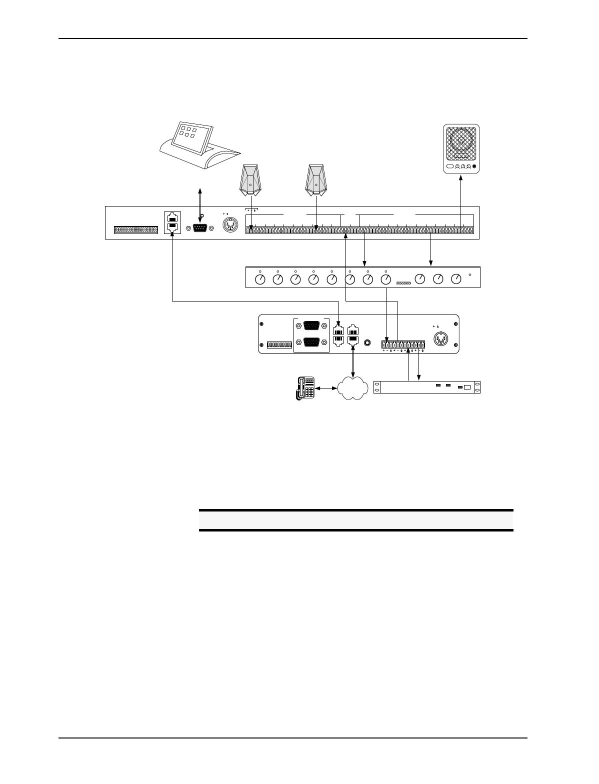
Typical EF1210
Connections The EF1210 will typically be connected to other equipment in a single zone setup as
shown below in Figure 5.
• Connect each of the 8 MIC/LINE INPUTS to a microphone. The MIC/LINE INPUT
accepts mini-Phoenix connectors. See “Connector Pinouts” on page 88 for
pinouts.
• Connect each of the 8 LINE OUTPUTS to the inputs of an automixer or matrix
mixer. Each LINE OUTPUT uses a mini-Phoenix connector.
• Connect the zone output (ZONE A or ZONE B) to an amplifier or powered loud-
speaker.
• Connect the reference input (AEC A or AEC B) to TO AEC on the EF200 (con-
nect only one reference per EF200) or to the output of the CODEC.
• Connect the output of your automixer to FROM AEC on the EF200 or to the input
of your CODEC.
• If RS-232 remote control is desired, connect the RS-232 REMOTE CONTROL port
of the EF1210 to the remote control device, such as an RS-232 interface to a
touch panel or a COM port on a personal computer. Connect the ASPI BUS OUT
on the EF1210 to the ASPI BUS IN on the EF200, if you are using an EF200
Figure 5. Typical EF1210 Connections
microphone
CODEC/hybrid
TX RX
POWERED SPEAKER
POWER LOW HIGH VOLUME MI
C
PSTN
microphone
. . .
. . .
TO PHONE
TO LINE
ASPI BUS
OUT
ASPI BUS
IN
LOGIC IN/OUT
RESERVED (SET TO OFF)
RESERVED (SET TO OFF)
NOISE SUPPRESSION
DEVICE ID 4
DEVICE ID 3
DEVICE ID 2
DEVICE ID 1
DEVICE ID 0
FROM
AEC TO
AEC FROM
REMOTE TO
REMOTE
EF400
INTERFACE
AGC
EPROM OVERRIDE
O
N
O
FF
REMOTE CONTROL
RS-232
5, 15 VDC
EF200 Phone Add (Optional)
EF1210
ON
POWER
Automatic
Microphone
Mixer
Remote Control System
(Optional) 8 microphones
ASPI Bus Connection for RS-232 Control Reference
Input
8 Line Level Signals
REMOTE CONTROLREMOTE CONTROL
ASPI BUS IN
ASPI BUS OUT RS-232
L
INE
L
INE
L
INE
L
INE
L
INE
MIC/LINE INPUTS
ZONE
A
5, 15 VDC 5, 12 VDC
MIC 1
PHANTOM 1
MIC 2
PHANTOM 2
DEVICE ID 8
DEVICE ID 4
DEVICE ID 2
DEVICE ID 1
21
DEVICE ID 16
MIC 3
PHANTOM 3
MIC 4
PHANTOM 4
MIC 5-8
PHANTOM 5
PHANTOM 6
PHANTOM 7
PHANTOM 8
436587 PLAY
AMIX
IN AEC BAEC A 21436587 REC TO
CODEC
AEC REF
RESERVED
RESERVED
LINE OUTPUTS
ZONE
B
PIN 2: TX
3: RX
15
AUX
IN
PIN 2: TXD
3: RXD
Caution! Set mixer inputs to 0 dBu line level, phantom power OFF.

EF1210 USER MANUAL
22 http://www.aspi.com Copyright © 1999, All Rights Reserved
Phone Add.
• Connect the external power supply to the POWER SUPPLY INPUT jack of the
EF1210.
Playback/Record The EF1210 provides the capability to record and play back audio to your conference.
Playback allows you to play the audio output of an external device, such as a televi-
sion or VCR, to the conference. Record allows you to record the audio of the confer-
ence to an external device, such as a tape recorder.
To implement the playback function with the EF1210, a playback signal must be
added to both the local audio (Zone) output and the remote output (the signal sent to
the CODEC or other terminal communication device). To implement the record
function, both the local audio and the remote CODEC signal must be mixed and out-
put to a recording device. Since the remote output will normally be produced by an
automixer external to the EF1210, the output of the automixer must be available to be
mixed with the REC and AUX IN signals. This mixing may be implemented using an
external matrix mixer if available, or using the internal mixers provided in the
EF1210. In addition to the convenience of using the EF1210 mixers, the EF1210 pro-
vides remote control of the level of the AUX IN signal so that weak recordings may be
boosted to be audible at both ends.
To use the EF1210 Playback mixer, the output of the automixer must be brought in to
the AMIX IN input on the EF1210, and the input to the CODEC (or other remote ter-
minal device) must be taken from the TO CODEC output of the EF1210. The AUX IN
input on the EF1210 will be added internally to the TO CODEC signal, and also to the
ZONE A output.
Note. The external RS-232 control device may be connected to any ASPI
device to control all ASPI devices that are linked via the ASPI Bus.
Figure 6. Block diagram of record and playback connections with the EF1210.
EF1210
CH 1
CH 8
CH 7
CH 6
CH 5
CH 4
CH 3
CH 2
OUT 1
OUT 8
OUT 7
OUT 6
OUT 5
OUT 4
OUT 3
OUT 2
ZONE A
Auto
Mixer CODEC
REC AUX
IN TO
CODEC AMIX
IN
TAPE RECORDER
auto-reverse
12:00
VCR
AEC A

ADVANCED INSTALLATION
ASPI Digital - The Sound of DSP Technical Support: 404.892.3200 23
To use the internal EF1210 Record mixer, the output of the automixer must be
brought in to the AMIX IN input on the EF1210. The input to the CODEC can come
from the automixer output as well or may be taken from the TO CODEC output of the
EF1210. The REC output will carry a mix of the AMIX IN and the AEC A signals.
Alternatively, you can do this mixing externally (connect playback output of external
program audio device to an automixer input). If record and playback signals are gen-
erated using an external mixer, the AUX IN and AMIX IN inputs and the REC and TO
CODEC outputs will not be used on the EF1210.
Playback and record are only available with the Reference A (AEC A) and Zone A
signals. If two zones are used, playback will NOT function properly in Zone B
because it will only be added to Reference A input signal from the far-end.
Using playback and record in the second zone of a multi-zone system will require
using the matrix mixer to create appropriate mixes outside of the EF1210.
See Figure 7 on page 23 below for the interconnection of AUX IN and REC input and
output, respectively.
To record,
• Connect the REC output of the EF1210 to the audio input on the recording
device.
• Connect AMIX IN to the output of the automixer or matrix mixer.
• Connect TO CODEC to FROM AEC on the EF200 or the input of the CODEC.
For playback,
• Connect the AUX IN of the EF1210 to the audio output of the playback
device.
• Connect AMIX IN to the output of the automixer or matrix mixer.
Note. If the EF1210 AUX IN is not used, the playback signal should be
mixed with the AEC Reference signal rather than with the Zone
output signal for local playback.
Figure 7. Playback and Record in the EF1210
EF1210
+ ++
GainGain
Aux
In
Rec To
CODEC
Amix
In
Level
adjust
Ch 5
AEC Ch 6
AEC
Level
adjust
Line
AEC
Reference
B
+-
A/D
AEC
Reference
A
+-
Line
A/D
Ch 3
AEC Ch 4
AEC
. . . . . .

EF1210 USER MANUAL
24 http://www.aspi.com Copyright © 1999, All Rights Reserved
• Connect TO CODEC to FROM AEC on the EF200 or the input of the CODEC.
Note. When using the internal EF1210 Record and Play circuitry, a sig-
nal being played back will NOT be recorded to avoid the potential
of a feedback loop caused by the record/playback device.

ADVANCED INSTALLATION
ASPI Digital - The Sound of DSP Technical Support: 404.892.3200 25
Figure 8 on page 25 depicts connections on the EF1210 for record and playback.
Figure 8. EF1210 Connections for Record and Playback
microphone
CODEC/hybrid
TX RX
POWERED SPEAKER
POWER LOW HIGH VOLUME MI
C
PSTN
microphone
. . .
. . .
TAPE RECORDER
auto-reverse
12:00
VCR
TO PHONE
TO LINE
ASPI BUS
OUT
ASPI BUS
IN
LOGIC IN/OUT
RESERVED (SET TO OFF)
RESERVED (SET TO OFF)
NOISE SUPPRESSION
DEVICE ID 4
DEVICE ID 3
DEVICE ID 2
DEVICE ID 1
DEVICE ID 0
FROM
AEC TO
AEC FROM
REMOTE TO
REMOTE
EF400
INTERFACE
AGC
EPROM OVERRIDE
O
N
O
FF
REMOTE CONTROL
RS-232
5, 15 VDC
EF200 Phone Add (Optional)
EF1210
ON
POWER
Automatic
Microphone
Mixer
ASPI Bus Connection for RS-232 Control
Remote Control System
(Optional)
8 microphones
Record and Play Devices
Reference
Input
Output to EF200
(optional)
or CODEC
Play Input
Record Output
REMOTE CONTROLREMOTE CONTROL
ASPI BUS IN
ASPI BUS OUT RS-232
L
INE
L
INE
L
INE
L
INE
L
INE
MIC/LINE INPUTS
ZONE
A
5, 15 VDC 5, 12 VDC
MIC 1
PHANTOM 1
MIC 2
PHANTOM 2
DEVICE ID 8
DEVICE ID 4
DEVICE ID 2
DEVICE ID 1
21
DEVICE ID 16
MIC 3
PHANTOM 3
MIC 4
PHANTOM 4
MIC 5-8
PHANTOM 5
PHANTOM 6
PHANTOM 7
PHANTOM 8
436587 PLAY
AMIX
IN AEC BAEC A 21436587 REC TO
CODEC
AEC REF
RESERVED
RESERVED
LINE OUTPUTS
ZONE
B
PIN 2: TX
3: RX
8 Line Level Signals
15
AUX
IN
PIN 2: TXD
3: RXD

ADVANCED INSTALLATION
ASPI Digital - The Sound of DSP Technical Support: 404.892.3200 27
CALIBRATION
For the EF1210 to work effectively, it must be calibrated properly to receive correct
levels from the surrounding equipment, such as microphones, amplifier, and CODEC.
The calibration procedure is required only to adjust the EF1210 to accommodate the
electrical characteristics of your conferencing equipment. The procedure allows you
to connect the widest possible variety of equipment to your EF1210. It does not train
the AEC. The EF1210 does not require training.
In calibration mode, the EF1210 generates a precise noise signal for measuring the
characteristics and sensitivity of the microphone. You only need to perform this cali-
bration at the initial installation. You do not have to calibrate the EF1210 each time
it is used.
Calibration Steps • Calibration Step 1: Calibrating Microphone Input Channels (page 29)
• Calibration Step 2: Calibrating Zone Outputs, Check Acoustic Gain (page 30)
• Calibration Step 3: Calibrating AEC Reference Inputs (page 32)
• Calibration Step 4: Calibrating for Playback and Record (page 33). This step
may be skipped if you are not using playback and record on the EF1210.
• Calibration Step 5: Zone/Reference Setup (page 34)
Acoustic Gain Acoustic gain is the maximum amplification that may be applied to a room’s audio
before being picked up by the microphone(s). The volume control may be set at a
lower level than this maximum amplification, but must not be set higher. Too much
acoustic gain occurs if the loudspeaker volume going into the microphone is louder
than the local talker’s volume. This may happen as a result of a combination of the
following setups: the loudspeaker volume is turned up too much, the microphone
level is too high, the microphone is too close to the loudspeaker, or the talker is not
talking close enough to the microphone relative to the loudspeaker volume. Acoustic
gain is commonly misunderstood, so when the audio in a room is not loud enough, it
seems logical to turn up the volume on the amplifier or loudspeaker. This is often not
the best remedy. For example, it may be necessary to turn up the reference input level
instead. Breaking through the acoustic gain threshold can cause echoes and howling
as loudspeaker levels overpower the microphones.
The calibration procedure will outline how to associate a volume level with the acous-
tic gain of a room. Refer to “Check Acoustic Gain” on page 31.
Note. When calibrated for the particular microphone and CODEC
setup, the EF1210 will provide years of service without recalibra-
tion. If the signal levels are not calibrated, the performance of the
EF1210 will not be satisfactory. When the signal levels are cali-
brated correctly, the EF1210 easily and automatically handles any
type of signals and changes in room acoustics to provide unparal-
leled echo cancellation performance.
Note. If you decide to use a different kind of microphone once the
EF1210 has been calibrated, the microphone inputs on the
EF1210 will be need to be recalibrated.

EF1210 USER MANUAL
28 http://www.aspi.com Copyright © 1999, All Rights Reserved
Two Methods of
Calibration The EF1210 can be calibrated two ways: calibrating with a computer or without. We
recommend using a computer for calibration because it is an easier procedure and it is
more precise. If you have a computer, please refer to our on-line document for com-
puter calibration procedures. See “Calibrating With a Computer” below for our web
address. If you do not have a computer, please refer to ““Calibrating Without a Com-
puter” on page 28” for front panel setup.
CALIBRATING WITH A COMPUTER
Included in your shipment of the EF1210 is a diskette containing the EFPanel Control
Software and a PDF version of the EFPanel User Manual, which includes installation
instructions. Install EFPanel and use it to calibrate the EF1210 with a computer.
Also included is a hardcopy of this manual. This control software and manual may be
changed and updated periodically, so please visit our website at http://www.aspi.com
for the most recent versions.
CALIBRATING WITHOUT A COMPUTER
In Calibration mode, the SETUP LED will blink to let you know which setup step you
are currently executing. The different modes are shown in Table 3 below. Press the
AUX IN LEVEL/SETUP button to move from one Calibration step to the next. When
you have finished Calibration Step 5, press the AUX IN LEVEL/SETUP button again to
exit Calibration mode; any changes that you made will be saved as the default power-
on settings when you exit the Calibration procedure.
If you miss a Calibration step or lose your place and get to the wrong Calibration step,
you may either continue and come back to the missed step later or exit Calibration
mode (by pressing AUX IN LEVEL/SETUP button repeatedly until the SETUP LED is no
longer illuminated), re-enter Calibration mode, and resume Calibration at the step that
you missed. If you wish to exit Calibration mode and discard any changes that you
made, you must cycle power on the EF1210 before exiting Calibration mode.
Figure 10. Legend for calibration drawings.
CALIBRATION MODE
MIC Input Calibration SETUP LED blinks once per period
ZONE Output Calibration SETUP LED blinks twice per period
AEC REF Input Calibration SETUP LED blinks three times per period
Calibrating for Playback and Record SETUP LED blinks four times per period
Zone/Reference Setup SETUP LED blinks five times per period
Table 3: Visual indication of calibration mode.
Le
g
end:
LED Off LED On ButtonLED Blinking
SETUP

ADVANCED INSTALLATION
ASPI Digital - The Sound of DSP Technical Support: 404.892.3200 29
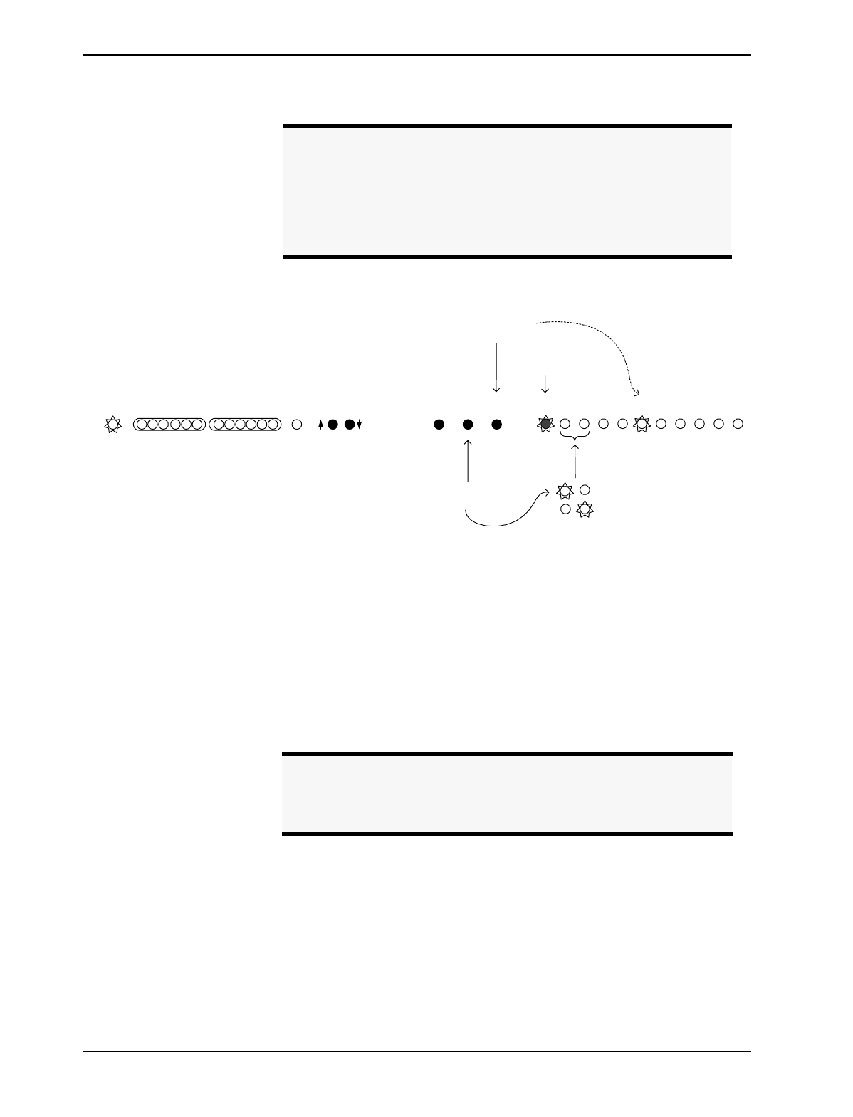
CALIBRATION STEP 1: CALIBRATING MICROPHONE INPUT CHANNELS
1.1. Press and hold the AUX IN LEVEL/SETUP button and the INPUT SELECT button for
two seconds to enter configuration mode of the EF1210. For Calibration Step 1,
the SETUP LED will blink once per period. For this step you will need a Sound
Level Meter (SPL Meter).
1.2. If necessary, press the REF SELECT button to select which zone the pink noise is
being played in.
• When you first enter configuration mode, pink noise is played in both Zone
A and Zone B.
•Press R
EF SELECT for no pink noise in Zone A or Zone B.
•Press R
EF SELECT again for pink noise in Zone A.
•Press R
EF SELECT again for pink noise in Zone B.
• Repeated pressing of REF SELECT will cycle through these four modes. See
Figure 11 on page 29.
1.3. Press the INPUT SELECT button to choose the input channel.
1.4. Set the SPL meter (Sound Level Meter) to C weighted, slow response. Choose
the appropriate dB SPL range using Table 4 below based on microphone type
and the talker’s distance from the microphone.
1.5. Place the SPL meter beside the microphone. Point the SPL meter and the micro-
Note. One period equals the number of blinks per step plus one off-time.
Figure 11. Calibrating Mic Inputs
STEP 1.1: Press and
hold AUX IN LEVEL/
SETUP button
and
INPUT SELECT for 2
seconds to enter
configuration mode
STEP 1.3:
press to select
channel for
calibration LEDs light to
indicate which
channel is selected
LED blinks
once for
microphone
calibration
noise level
measured at mic
should be at the
appropriate SPL
level from Table 3
pink noise to both zones
no noise generated
pink noise to zone A
pink noise to zone B
STEP 1.7: adjust
level until 3 green
and 1 yellow LEDs
are lit (repeat for
each channel)
STEP 1.2: press to
select noise source
-12 -7 -3 0 3 20 dB -12 -7 -3 0 3 20
AUX IN
LEVEL REF
SELECT INPUT
SELECT SETUP AEC
AAEC
B12345678
INPUTPOWER REMOTE MUTE
ALL LEVEL
ADJUST
SETUP
MICROPHONE TYPE TYPICAL DISTANCE FROM
TALKER (FT.) SPL LEVEL
(dB)
Lavalier 6 inches to 1 foot 89 dB SPL
Gooseneck 1-2 feet 77 dB SPL
Boundary or other tabletop 2-3 feet 73 dB SPL
Ceiling 4 or more feet 69 dB SPL
Table 4: Typical distance from microphone to talker and appropriate dB SPL level.

ADVANCED INSTALLATION
ASPI Digital - The Sound of DSP Technical Support: 404.892.3200 31
2.2. Press the REF SELECT button to choose which output is being calibrated. A nom-
inal level noise signal is played through the selected Zone output(s).
• When the EF1210 first enters Zone Output calibration, the AEC A and AEC
B LEDs are lit, indicating that both zones will be calibrated. Use this if you
want to calibrate both zones at the same time.
• If you want to calibrate only Zone A, press the REF SELECT button to select
Zone A. Only the AEC A LED lights, indicating Zone A.
• If you want to calibrate only Zone B, press the REF SELECT button again to
select Zone B. Only the AEC B LED lights, indicating Zone B.
2.3. Check the specifications of your room audio amplifier input:
• If it expects consumer level (-10 dBV) input, press the LEVEL ADJUST
DOWN button once.
• If it has a balanced input connector and expects 0 dBu input level, press the
LEVEL ADJUST UP button once.
More precise level adjustments can be made with the RS-232 commands (see the
GAINZ command on page 68 of the Command Set Reference.
2.4. If you selected only one of the Zone Outputs, repeat for the second Zone Output.
For visual instructions, refer to Figure 12 on page 31.
Check Acoustic Gain.
2.5. At this point you are ready to calibrate the absolute maximum room audio ampli-
fication level. For this step, you should ensure that the microphones have been
returned to their normal operating location and orientation. This procedure uses
a known nominal electrical noise signal level at the zone output to let you see if
any of the microphone input channels will exceed the permissible acoustic gain
during normal conferencing operation. The level of this noise signal is such that
if any microphone input channel registers more than three green LEDs on the
EF1210 INPUT SIGNAL LEVEL METER, the acoustic gain limit of that microphone
channel has been reached. This represents the maximum amplification that may
be applied to the room audio. The room audio may be run at any level below this
threshold, but should not be amplified beyond this level unless the acoustic gain
is reduced by some other means (See “Acoustic Gain” on page 44).
All microphones should be checked in this step as verification that no micro-
phone inputs or zone outputs have been miscalibrated.
Figure 12. Calibrating Zone outputs
AUX IN
LEVEL REF
SELECT INPUT
SELECT SETUP AEC
AAEC
B12345678
INPUTPOWER REMOTE MUTE
ALL LEVEL
ADJUST
SETUP
STEP 2.6: adjust external
amplifiers/loudspeakers so that
no more than 3 green LEDs are
lit (repeat for each channel)
-12 -7 -3 0 3 20 dB -12 -7 -3 0 3 20
STEP 2.2:
press to select
noise source
noise to both zones (recommended)
noise to zone A
noise to zone B
STEP 2.6: press
to select
channel;
check level LEDs light to
indicate which
channel is selected
LED blinks
twice for Zone
calibration
STEP 2.3a: press
if amp expects
consumer level
input (-10 dBV)
STEP 2.3b:
press if amp
expects 0 dBu
balanced input

ADVANCED INSTALLATION
ASPI Digital - The Sound of DSP Technical Support: 404.892.3200 33
calibration. For Calibration Step 3, the SETUP LED will blink three times per
period.
For this step, you will need a live connection to a remote conferencing site (or
two sites if you are configuring the EF1210 for two AEC reference inputs).
• If you are configuring the EF1210 for operation with one AEC reference
input, you will calibrate the AEC A signal.
• If you are configuring the EF1210 for operation with two AEC reference
inputs, you will calibrate both the AEC A and the AEC B signals.
3.2. Press REF SELECT to select between AEC A and AEC B. This will be indicated
by the front panel AEC A and AEC B LEDs. During this step, all other LEDs
(INPUT CHANNEL) will be extinguished.
3.3. Have the person at the remote end of the conferencing link sit at a normal dis-
tance from a microphone and talk at a normal level while you observe the signal
activity on the REMOTE SIGNAL LEVEL METER.
3.4. Adjust the AEC Reference Input by pressing the LEVEL ADJUST buttons until the
first yellow (0 dB) LED lights regularly during normal speech at the remote end,
and the second yellow LED flickers occasionally.
3.5. If you are calibrating two AEC Reference Inputs, switch to the other by pressing
REF SELECT and repeat the calibration for the second reference signal.
Refer to Figure 13 on page 33.
CALIBRATION STEP 4: CALIBRATING FOR PLAYBACK AND RECORD
4.1. Once the AEC Reference Inputs have been calibrated, press AUX IN LEVEL/
SETUP again to switch to Playback/Record calibration. For Calibration Step 4,
the SETUP LED will blink four times per period. This step calibrates the TO
Figure 13. Calibrating AEC Reference Inputs
-12 -7 -3 0 3 20 dB -12 -7 -3 0 3 20
AUX IN
LEVEL REF
SELECT INPUT
SELECT SETUP AEC
AAEC
B12345678
INPUTPOWER REMOTE MUTE
ALL LEVEL
ADJUST
SETUP
STEP 3.4: adjust
level until person
talking at remote
site rarely flickers
second yellow LED
STEP 3.2: press
to select
reference input
source
AEC A input selected
AEC B input selected
LED blinks three
times for AEC
Reference calibration
Caution! If you skip this calibration step, you will compromise the
performance of the EF1210. The audio coming from the
remote end may be too low, so if you turn up the loud-
speaker to compensate, the acoustic gain will be affected.

EF1210 USER MANUAL
34 http://www.aspi.com Copyright © 1999, All Rights Reserved
CODEC signal. No other calibration is necessary for Playback/Record.
The TO CODEC signal may be adjusted to match the level required by your
codec (or other remote terminal equipment) input.
4.2. Press the LEVEL ADJUST DOWN button to set the TO CODEC level to -10 dBV.
Press the LEVEL ADJUST UP button to set the TO CODEC level to 0dBu. More
precise level adjustments can be made with RS-232 commands (See the GAINC
command on page 62 in the Command Set Reference.).
Refer to Figure 14 on page 34.
CALIBRATION STEP 5: ZONE/REFERENCE SETUP
5.1. Enter Zone/Reference Setup mode by pressing AUX IN LEVEL/SETUP after step-
ping through the normal configuration sequence. For Calibration Step 5, the
SETUP LED will blink five times per period.
If you are only using a single zone, you may omit this step.
During Calibration Step 5, you may set the EF1210 to use different AEC Refer-
ence Inputs for each channel. The reference signal used with channel 1 will be
used as Zone A output, and the reference used with channel 8 will be used as
Zone B output. Microphones on the input channels must be placed in the sound
field of the appropriate Zone output for the EF1210 to operate correctly; other-
wise echoes will not be cancelled. In other words, if for example the microphone
on channel 3 is in the soundfield of the loudspeaker connected to the Zone B out-
Note. You may skip this step if you are not using playback and record on
the EF1210
Figure 14. Calibrating for playback and record.
-12 -7 -3 0 3 20 dB -12 -7 -3 0 3 20
AUX IN
LEVEL REF
SELECT INPUT
SELECT SETUP AEC
AAEC
B12345678
INPUTPOWER REMOTE MUTE
ALL LEVEL
ADJUST
SETUP
STEP 4.2a:
press to set
CODEC OUT
level to -10
dBV
STEP 4.2b:
press to set
CODEC OUT
level to 0 dBu
LED blinks four
times for record
and playback
calibration
ADVANCED INSTALLATION
ASPI Digital - The Sound of DSP Technical Support: 404.892.3200 35
put, channel 3 must be configured to use Reference B (AEC B) as its reference.
5.2. Use the REF SELECT button to select an AEC Reference (AEC A or AEC B) to be
used with the channel indicated by the Input channel LEDs. The AEC A or AEC
B LED will illuminate to indicate the selected reference.
5.3. Press the INPUT SELECT button to select the next input channel, and select AEC A
or AEC B as reference for that channel. Continue until all eight input channels
have been configured.
5.4. You may now exit configuration mode and resume normal operation by pressing
the AUX IN LEVEL/SETUP button.
Refer to Figure 15 on page 35.
Note. If you are using only one reference signal (Reference A), all
microphones must be configured to use that reference signal. If
you are using two reference signals (Reference A and Reference
B), Input Channel 1 must be associated with Reference A (AEC A)
and Input Channel 8 must be associated with Reference B (AEC
B). The other 6 microphones can be associated with either refer-
ence.
Figure 15. Zone/Reference Setup
-12 -7 -3 0 3 20 dB -12 -7 -3 0 3 20
AUX IN
LEVEL REF
SELECT INPUT
SELECT SETUP AEC
AAEC
B12345678
INPUTPOWER REMOTE MUTE
ALL LEVEL
ADJUST
SETUP
STEP 5.2: press to
select reference zone zone A selected
zone B selected
STEP 5.3: press to
select channel for
calibration LEDs light to
indicate which
channel is selected
LED blinks
five times for
zone/ref setup
Note. Once you enter setup from the front panel, the configuration will
be saved as the power-on default once you exit setup. If you wish
to discard any changes you made, you must cycle power on the
EF1210 before you press the SETUP button to exit Setup.

EF1210 USER MANUAL
38 http://www.aspi.com Copyright © 1999, All Rights Reserved
OPERATING THE EF1210
USING THE EF1210 WITHOUT RS-232 CONTROL
Changing Level
Display on INPUT and
REMOTE LED Meters
When the EF1210 is in normal operating mode, pushing the INPUT SELECT button will
allow you to see levels of each input channel on the INPUT LED meter. The green
LED corresponding to an input channel will light if the levels of that channel are cur-
rently displayed on the INPUT LED meter. In the same way, pushing the REF SELECT
button will allow you to see the levels of each reference input on the REMOTE LED
meter. A yellow LED will indicate which reference (AEC A or AEC B) is displayed
on the meter.
Adjusting Volume in
Zones The reference LEDs (AEC A or AEC B) do double duty. They not only indicate
which Reference Input is currently displayed on the REMOTE LED meter, but also
indicate which Zone Output is affected when the LEVEL ADJUST buttons are pressed.
The AEC A LED indicates that ZONE A’s volume is being adjusted by the LEVEL
ADJUST button. The AEC B LED indicates that ZONE B’s volume is being adjusted
by the LEVEL ADJUST button. The output levels can be adjusted up to 6 dB above and
12 dB below the nominal zone output level. The nominal zone output level is 6 dB
below the level selected in Calibration Step 2: Calibrating Zone Outputs.
Adjusting Playback
Levels The AUX IN input and REC output signals are preset to -10 dBV signal levels. The
level of the AUX IN signal may be adjusted during normal operation to compensate for
low or high audio level from an external playback device.
1. During normal operation, press and hold the AUX IN LEVEL/SETUP button while
using the LEVEL ADJUST buttons to adjust the level of the playback signal. The
level-adjusted AUX IN signal is mixed with the AMIX IN signal (nominally 0dBu)
and sent to the TO CODEC connector. It is also mixed with the AEC A signal
and played over the Zone A output.
Muting To mute channels while using the EF1210 without RS-232 control, for push-to-talk
microphones for example, we suggest using the mute control capability on the mixer
rather than using a microphone with mute built inside it. The AEC will perform bet-
ter using this method because it allows the speech to be processed inside the EF1210
before being muted instead of totally cutting off the speech so that the AEC has to
readapt when the microphone comes on again.
Splitting zones Calibrate using calibration procedures. When using more than one zone, refer to
“Calibration Step 5: Zone/Reference Setup” on page 34 to associate each microphone
input channel with a reference. If you are using two reference signals (Reference A
and Reference B), Input Channel 1 must be associated with Reference A (AEC A)
and Input Channel 8 must be associated with Reference B (AEC B). The other 6
microphones can be associated with either reference

OPERATING THE EF1210
ASPI Digital - The Sound of DSP Technical Support: 404.892.3200 39
USING THE EF1210 WITH RS-232 CONTROL
You can control all of the EF1210’s features with an RS-232 remote control device.
The instructions below explain which RS-232 commands are needed to accomplish
each function. Users may not need to know these commands, since they may be hid-
den behind the user interface of the remote control device. A full Command Set Ref-
erence is provided at the end of this manual starting on page 53.
Serial Port Setup For RS-232 control, use an RS-232 cable — do not use a null modem. Refer to “Con-
nector Pinouts” on page 88 for pin connections for the RS-232 cable. The RS-232
port on the remote control device should be set to 9600, 8-N-1.
Changing Level
Display on INPUT and
REMOTE LED Meters
When the EF1210 is in normal operating mode, the input channel level displayed on
the INPUT LED meter can be checked and adjusted using the following commands
from the RS-232 command set:
When the EF1210 is in normal operating mode, the Reference Input level displayed
on the REMOTE LED meter can be checked and adjusted using the following com-
mands from the RS-232 command set::
Command Description Effects
SELECTI
n
Set front panel
INPUT LED meter to
display input chan-
nel n.
The level of input channel n will be
displayed on the INPUT LED meter
and the green LED of the channel will
light.
SELECTI? Request current
assignment of front
panel INPUT LED
meter.
The EF1210 returns channel n, which
indicates that the front panel INPUT
LED meter is currently set to display
input channel n.
n ranges from 1 to 8.
Command Description Effects
SELECTR
c
Set front panel
REMOTE LED meter
to display Reference
input c.
The level of Reference input c will be
displayed on the REMOTE LED meter
and the yellow LED of the reference
will light.
SELECTR? Request current
assignment of front
panel REMOTE LED
meter.
The EF1210 returns Reference input c
which indicates that the front panel
REMOTE LED meter is currently set to
display Reference input c.
c is either A or B.

EF1210 USER MANUAL
40 http://www.aspi.com Copyright © 1999, All Rights Reserved
Adjusting Volume in
Zones The volume in the zones can be checked and adjusted using the following commands
from the RS-232 command set:
During normal operation, the zone output levels will be set 6 dB lower than the
selected level (amplifier acoustic gain limit) to allow the EF1210 LEVEL ADJUST con-
trols to apply a volume adjustment to the room audio signal in the range +6 dB to -12
dB.
Adjusting Playback
Levels The AUX IN input and REC output signals are preset to -10 dBV signal levels. The
level of the AUX IN signal may be adjusted during normal operation to compensate for
low audio level from an external playback device. The playback level can be adjusted
using the following commands from the RS-232 command set:
Muting The channels on the EF1210 can be muted using the RS-232 command set. Using the
MUTEI command will mute the outgoing audio on LINE OUTPUT of the channel that
is muted. The MUTE ALL LED will light only when all channels are muted.
Command Description Effects
GAINZ
c
xSet zone c output
gain to x. Zone c output gain set to x dB; yellow
LED on AEC c will light.
c is either A or B.
x ranges from 0 to 20 dB.
GAINZ
c
?Request zone c out-
put gain. Current gain for zone c is returned to
remote control device.
Note. See the “GAINZc - set ZONE output gain on output c” on page 68
for a more detailed description of the zone output gain x.
Command Description Effects
GAINPx Set playback input
gain to x. Playback input gain set to x dB.
x ranges from 0 to 15 dB.
The default is 8 dB.
GAINP? Request playback
input gain. Current gain for playback is returned
to remote control device.
Note. See the “GAINP - set PLAYBACK input gain (on AUX IN input)”
on page 65 for a more detailed description of the playback input
gain x.
Command Description Effects
MUTEI
n
Mute channel nOutgoing audio on channel n is muted.
MUTEI* Mute all channels All channels are muted; the MUTE ALL
LED lights.

OPERATING THE EF1210
ASPI Digital - The Sound of DSP Technical Support: 404.892.3200 41
Wideband NC vs.
AEC mode Having the option to turn the AEC off for wideband noise cancellation is particularly
useful when used in a system that has both conferencing capabilities and sound rein-
forcement. For this system, we suggest programming the remote control device to
turn on the AEC on each channel of the EF1210 if the room is being used for a confer-
ence (when the phone or CODEC is connected). At any other time, program the
remote control device to turn on wideband noise cancellation for sound reinforce-
ment.
Splitting zones Use EF Panel Control Software to calibrate the EF1210. On Calibration Step 5 when
using more than one zone, associate each microphone input channel with either Ref-
erence A or Reference B. If you are using two reference signals (Reference A and
Reference B), Input Channel 1 must be associated with Reference A (AEC A) and
Input Channel 8 must be associated with Reference B (AEC B). The other 6 micro-
phones can be associated with either reference
Command Description Effects
SR16 Set sample rate to 16
kHz. The normal operating mode is 16
kHz. In this mode, AEC can be
enabled or disabled.
SR48 Set sample rate to 48
kHz. The wideband mode (48 kHz) is pro-
vided for applications that require
high-fidelity noise cancellation. In
this mode, AEC is disabled.
SR? Request sample rate. Current sample rate is returned to
remote control device.

EF1210 USER MANUAL
42 http://www.aspi.com Copyright © 1999, All Rights Reserved
TROUBLESHOOTING
NO OUTPUT TO LOUDSPEAKERS IN ZONE
You can’t hear the
remote end. Check the REMOTE LEVEL INDICATOR of the zone (use the REF SELECT button to
switch between Reference A and Reference B. If the LED graph meter shows activ-
ity, the EF1210 is receiving a signal. In this case, the problem is between the EF1210
and the loudspeaker.
If there is no activity on the REMOTE LEVEL INDICATOR, the EF1210 is not receiving
a signal. In this case, the problem is between the EF1210 and the microphone(s) on
the remote end.
Check the CODEC (or EF200) output by connecting it directly to the amplifier or
powered speaker. If you hear nothing, the EF1210 is not causing the problem and the
source of the problem is elsewhere in the system.
Make sure the CODEC or EF200 is connected to the appropriate reference input
(AEC A or AEC B) from the appropriate zone.
Make sure the CODEC or EF200 is turned on.
Make sure everything on the remote end is working properly.
Make sure the cables are not broken. Check the cable pinouts.
If you see signal activity on the REMOTE signal meter, make sure the appropriate zone
output (ZONE A or ZONE B) is connected to the amplifier or powered loudspeaker
input.
Make sure the amplifier or powered loudspeaker is on and that the volume is at an
appropriate level. If the zone output level needs adjusting, choose the appropriate
zone by pressing the REF SELECT button on the front panel. The yellow AEC A or
AEC B LEDs indicate not only the reference input but also the corresponding zone
output.
NO OUTPUT TO REMOTE END
Remote end can’t
hear you. Check each microphone’s level on the INPUT LEVEL INDICATOR to make sure there is
activity when you speak into the microphone. You can display each microphone’s
input level by using the INPUT SELECT button to cycle through each microphone. If
the INPUT LEVEL INDICATOR shows activity when you speak into the microphone, the
EF1210 is receiving the microphone signal. This means the remote end is not receiv-
ing a signal from the EF1210.
Caution! When adjusting amplifier or powered loudspeaker levels, be
careful not to exceed the maximum amplification level that
you took note of in the Zone Output calibration (see “Check
Acoustic Gain” on page 31).

TROUBLESHOOTING
ASPI Digital - The Sound of DSP Technical Support: 404.892.3200 43
Check LINE OUTPUTS by connecting each output to the amplifier or powered loud-
speaker in the appropriate zone (turn the loudspeaker down to avoid howling). If the
loudspeaker emits sound when you speak into the microphone, the signal is making it
through the EF1210. This means there is a problem with the automixer, CODEC, the
CODEC connection, or a device on the remote end.
If the INPUT LEVEL INDICATOR does not display activity, the EF1210 is not receiving
the microphone signals. This means there is a problem with the microphone.
If the microphones you are using require phantom power, make sure it is enabled on
the appropriate channel on the EF1210 DIP switches. Make sure the phantom power
voltage is compatible with the microphone.
Make sure the automixer output is connected to the CODEC or EF200 input.
Make sure the CODEC or EF200 is turned on.
Make sure everything on the remote end is working properly.
Make sure the cables are not broken. Check the cable pinouts.
Make sure the microphone is plugged into the appropriate MIC/LINE INPUT.

EF1210 USER MANUAL
44 http://www.aspi.com Copyright © 1999, All Rights Reserved
RESIDUAL ECHO
You may hear residual echo if system levels are not set properly. Improper level set-
tings anywhere in the audio path can introduce nonlinearities that hamper the opera-
tion of the EF1210. If you hear residual echo, one of the following conditions may be
causing the problem.
Reverberation vs.
Echo Do not confuse the residual echo of remote speech with the reverberation of local
speech. Reverberation of local speech is caused when the speech signal arrives at the
microphone via several paths (the direct path and multiple reflections from surfaces in
the room). This is a local room phenomenon that gives the talker’s voice a hollow or
resonant sound (as heard at the remote end).
Reverberation is not an artifact of the echo canceller. It is mainly affected by the dis-
tance of the microphone from the speech source and by the resonances of the room.
While reverberation can be unpleasant, it is not compensated for by the AEC, which
only removes reflections of remote speech. If the remote end complains that they
hear echo, ensure that they are referring to hearing their own voice and not echoes of
local talkers.
You cannot remove the effects of reverberation by changing the EF1210’s settings,
but you can minimize reverberation by moving microphones closer to talkers and, if
necessary, adding acoustical treatment to the room.
Finding the Source
of Echo Try muting one channel at a time to see if the echo goes away when a particular chan-
nel is muted. You can mute the channel by using the MUTEI command on the
EF1210 or by muting it on the automixer (turn down volume of the microphone on
mixer or use the logic port control). If you find that the echo goes away when a par-
ticular channel is muted, the microphone may not be calibrated correctly. Check one
or more of the following issues.
Acoustic Gain The most common cause of poor echo cancellation performance is incorrectly
adjusted acoustic gain. This may be explained as follows. The reference signal seen
by the AEC is sent to the Zone output, where it is amplified and sent to the room loud-
speakers. The loudspeaker audio is coupled into the room microphones acoustically,
through direct and reflected acoustic paths, and perhaps also through mechanical cou-
pling. The microphone signal is then amplified and sent to the AEC as the local
microphone input signal. The acoustic gain of a microphone channel refers to the rel-
ative levels of the signal sent to the Zone output (before any amplification) and the
level of this signal that is reflected as the microphone input (after microphone ampli-
fication).
If the electrical level of the reflected signal picked up by microphone is the same as
the level of the electrical signal sent from the AEC to the Zone output, the acoustic
gain of this microphone channel is said to be 0 dB. If the reflected signal picked up
by the microphone is higher than the level of the signal sent to the Zone output, that
microphone channel has positive acoustic gain. The more positive the acoustic gain,
the harder the AEC must work to determine which signal is an echo and which is a
local speech signal.

EF1210 USER MANUAL
46 http://www.aspi.com Copyright © 1999, All Rights Reserved
METER, this indicates a possible problem with the acoustic gain on that microphone
channel.
If this excessive coupling activity level is evident on only one microphone input chan-
nel, that microphone channel should either be redirected to reduce coupling to loud-
speaker audio, or recalibrated as it will need to be turned down. If the excessive
coupling activity is observed on all (or most) microphone channels, then this indicates
either that the room audio is too loud or the reference signal may need to be recali-
brated (this will be indicated by observing low activity levels on the REMOTE SIGNAL
LEVEL METER).
Excessive
Microphone
Amplification
For the EF1210 to adapt effectively, saturation (overload or clipping) must not occur
at the A-D converter supplying the microphone input. Saturation introduces nonlin-
ear signal distortions into what the AEC expects is a linearly echoed version of the
remote speech.
Nonlinear distortion causes a degradation or divergence of the AEC’s internal model
of the room acoustics. In this situation, the EF1210 cannot effectively cancel room
echoes and a substantial amount of echo may be heard by the remote party.
Excessive microphone amplification also increases acoustic gain (See “Acoustic Gain
Failure” on page 45.). You can check for excessive microphone amplification by
observing the front panel INPUT LEVEL INDICATOR during a normal conference. The
first yellow LED should illuminate frequently. If the second yellow LED is illumi-
nated constantly during normal speech or if the red LED illuminates or even flickers,
reduce the microphone input level.
Insufficient
Microphone
Amplification
Grossly insufficient microphone gain degrades EF1210 performance and weakens the
out-bound speech power level. This has the effect of reducing the signal-to-noise
ratio of the microphone signal, which is analogous to raising the background noise
level in the room. Because this noise is uncorrelated with the echoes within the room,
the EF1210’s ability to adapt and cancel echoes is compromised.
A second effect of insufficient microphone gain is that the power of the microphone
input signal may be substantially lower than that of the remote input signal. This
Note. Before you readjust the Remote input levels, check to make sure
you are looking at the correct remote input level (AEC A or AEC
B) on the REMOTE LEVEL INDICATOR. Check to make sure that the
microphone that you are looking at is in the zone that you think it
is in and that you are looking at the correct channel on the INPUT
LEVEL INDICATOR.
Note. Before you readjust the microphone input levels, check to make
sure you are looking at the correct channel on the INPUT LEVEL
INDICATOR. Check also to make sure that you are looking at the
correct corresponding reference input level on the REMOTE LEVEL
INDICATOR.
Note. If you adjust the MIC/LINE INPUT level, you will affect the acoustic
gain. Check to make sure that the acoustic gain limit is not
exceeded. See “Check Acoustic Gain” on page 31.

TROUBLESHOOTING
ASPI Digital - The Sound of DSP Technical Support: 404.892.3200 47
reduces the ability of the decision logic to determine whether the AEC should be in
transmit, receive, or double-talk mode. This effect may reduce the effectiveness of
the EF1210 in canceling echoes.
You can check for insufficient microphone amplification by observing the front panel
INPUT LEVEL INDICATOR during normal conferencing conversation. The first yellow
LED should illuminate frequently. If the INPUT LEVEL INDICATOR never illuminates
beyond one or two green LEDs during normal speech, increase the microphone’s
input level.
Loudspeaker
Nonlinearity Overdriving the loudspeaker may distort the zone output signal and cause ineffective
AEC operation. The EF1210 relies on the linearity of the acoustic feedback path —
D-A, amplifier, loudspeaker, microphone, and A-D — to cancel acoustic echoes. If
you overdrive the loudspeaker, the acoustic reflections picked up by the microphone
do not match the signal fed to the loudspeaker. They are distorted copies of this sig-
nal. The EF1210 cannot effectively cancel this distorted signal.
If you suspect the loudspeaker is introducing nonlinearities into the room acoustic
path, take these steps to minimize its influence on the echo canceller.
• Keep the loudspeaker’s volume level at less than three-eighths of full scale. If
higher volume is required, the EF1210 should operate effectively at volume set-
tings of up to 50 percent of full scale. At more than 50 percent, most audio sys-
tems and loudspeakers introduce significant nonlinearities. The EF1210 may not
adapt under these conditions, and echoes may be heard.
• If the loudspeaker has a bass control, lower it. Excessive bass can cause a boomy
effect that is nonlinear. In addition, excessive bass may cause substantial
mechanical coupling to the microphone through vibrations induced in the hous-
ings and support structures.
• Increase the separation distance between microphones and the loudspeaker. The
EF1210 handles up to 10 dB of acoustic gain between the loudspeaker and the
microphone. You may be exceeding this limit if the loudspeaker is pointed
directly at the microphones or if the loudspeaker volume is excessive (loud-
speaker placement is not critical, but it should not be pointed directly at the
microphones).
REMOTE CONTROL PROBLEMS
If the remote control device doesn’t seem to be affecting the EF1210, there are a few
things you can check. Try sending commands that have a visible impact, like the
MUTEI command (muting all channels will cause the MUTE ALL LED to light). Also,
look for messages from the EF1210, like acknowledgment or error messages, if the
remote control device can display them.
Note. Before you readjust the microphone input levels, check to make
sure you are looking at the correct channel on the INPUT LEVEL
INDICATOR. Check also to make sure that you are looking at the
correct corresponding reference input level on the REMOTE LEVEL
INDICATOR.
Note. If you adjust the MIC/LINE INPUT level, you will affect the acoustic
gain. Check to make sure that the acoustic gain limit is not
exceeded. See “Check Acoustic Gain” on page 31.

EF1210 USER MANUAL
48 http://www.aspi.com Copyright © 1999, All Rights Reserved
Check Command
Syntax Make sure the commands that are being sent to the EF1210 have the correct syntax.
If only a couple of the commands aren’t being processed, there may be an error in the
syntax of those commands. Remember, the commands are case sensitive. Com-
mands should be typed with all capital letters. The EF1210 should return ERROR#
messages if the commands are typed incorrectly, as long as error messages are
enabled.
Check Device ID Make sure the Device ID of the EF1210 matches the Device ID of the commands that
are being sent. If they don’t match, the EF1210 will ignore all the commands. Try
sending a command to all devices (*** instead of Device Type and Device ID). If
this works but sending commands to a specific device doesn’t, the Device ID doesn’t
match.
Check RS-232 Make sure the RS-232 cable is connected securely to the EF1210 and the remote con-
trol device. Also, the RS-232 port on the remote control device should be set to 9600,
8-N-1.
CONTACTING TECHNICAL SUPPORT
If these troubleshooting guidelines don’t resolve the problem you are experiencing
with the EF1210, please check our web site (http://www.aspi.com) for the most cur-
rent technical support information (go to Technical Resources, then to Technical Sup-
port). If you have further questions, please contact us at:
Applications Engineering
ASPI Digital
1720 Peachtree St. NW Suite 220
Atlanta, GA 30309-2439
Phone: (404) 892-3200
Fax: (404) 892-2512
Email: help@aspi.com
Before contacting us, please review the warranty and repair policy on page 51.

TECHNICAL SPECIFICATIONS
ASPI Digital - The Sound of DSP Technical Support: 404.892.3200 49
TECHNICAL SPECIFICATIONS
COMPLIANCE
The EF1210 complies with the ITU G.167 Recommendation for AEC, FCC part 15,
MECHANICAL SPECIFICATIONS
Dimensions 19” (483 mm) W x 8.2” (208 mm) L x 1.75” (45 mm) H (full rack unit)
Weight 5.5 lb.
Connectors Audio: Mini (3.5mm) quick connect terminal blocks
RS-232: DB9F
ASPI Bus In/Out: RJ45
ELECTRICAL SPECIFICATIONS
Power 100 - 240 VAC; 50-60 Hz
Power Consumption 40 W
Phantom Power 28 V
Microphone Input -30 dBu to +0 dBu/-66 dBu to -33 dBu, nominal
Range is rear panel switch selectable
AEC Reference Input -20 dBu to +0 dBu, nominal, software adjustable
Line Output +0 dBu, nominal
Zone Output -10 dBV (-8 dBu) or 0 dBu, nominal, selectable +6 to -12 dB via front
panel setup.
-20 dBu to +0 dBu, nominal, software selectable via RS-232 setup.
Automixer Input 0 dBu, nominal
CODEC Output -10 dBV (-8 dBu) or 0 dBu, nominal, selectable via front panel setup.
-20 dBu to +0 dBu, nominal, software selectable via RS-232 setup.
Playback Input -10 dBV (-8 dBu), nominal, software selectable -8 to +8 dB gain
Record Output -10 dBV (-8 dBu), nominal
Input Impedance > 10 kOhms
Output Impedance 50 Ohms (drives 600 Ohms)
Headroom 20 dB, nominal
PERFORMANCE SPECIFICATIONS
Frequency Response with AEC on: 125 Hz - 7.25 kHz +/- 2 dB
in NC only mode (AEC off): 20 Hz - 22 kHz
Echo Cancellation Span 200 ms
Total Cancellation > 65 dB
Convergence Rate 30 dB/second
Noise Cancellation 6 dB or 10 dB, selectable

EF1210 USER MANUAL
50 http://www.aspi.com Copyright © 1999, All Rights Reserved
and CE requirements.
FCC Part 15 This equipment has been tested and found to comply with the limits for a Class A dig-
ital device, pursuant to Part 15 of the FCC Rules. These limits are designed to pro-
vide reasonable protection against harmful interference when the equipment is
operated in a commercial environment. This equipment generates, uses, and can radi-
ate radio frequency energy and, if not installed and used in accordance with the
instruction manual, may cause harmful interference to radio communications. Opera-
tion of this equipment in a residential area is likely to cause harmful interference in
which case the user will be required to correct the interference at his own expense.
The EF1210 also complies with the CE standards EN50081-1, EN50082-1, and
EN60950. Conformity of the equipment with those guidelines is attested by the CE
mark.
Warning! FCC Regulations state that any unauthorized changes or
modifications to this equipment not expressly approved by
the manufacturer could void the user’s authorization to
operate this equipment.

WARRANTY INFORMATION
ASPI Digital - The Sound of DSP Technical Support: 404.892.3200 51
WARRANTY INFORMATION
What is covered Any defect in materials or workmanship.
For how long Two years.
What we will do If your ASPI Digital product is defective and returned within two years of the date of
purchase, we will repair or, at our option, replace it at no charge to you.
If we repair your ASPI Digital product, we may use new or reconditioned replace-
ment parts. If we choose to replace your ASPI Digital product, we may replace it with
a new or reconditioned one of the same or similar design. The repair or replacement is
warranted for either (a) 90 days or (b) the remainder of the original two-year warranty
period, whichever is longer.
Limitations ASPI Digital shall not be responsible for special, incidental, indirect, or consequential
damages resulting from any breach of warranty, or under any other legal theory,
including but not limited to loss of profits, downtime, goodwill, damage to or replace-
ment of equipment and property, and any cost of recovering, reprogramming, or
reproducing any program or data stored in or used with ASPI Digital products.
Some states do not allow limitations on how long an implied warranty lasts, or the
exclusion of incidental or consequential damages, so the above exclusions or limita-
tions may not apply to you.
What we ask you to
do To obtain warranty service for your ASPI Digital product, call us at (404) 892-3200
or fax us at (404) 892-2512 and we will issue a Return Material Authorization number
(RMA#). Use the original packaging materials to return the product. Ship the product
prepaid to:
ASPI Digital
Attention: Warranty Repair
RMA# (Must be on package)
1720 Peachtree Street NW, Suite 220
Atlanta, Georgia 30309-2439 USA
Please be sure to include your name, company, address, phone number, and a descrip-
tion of the problem. After repairing or replacing your ASPI Digital product, we will
ship it to you via a surface carrier of our choice at no cost to you. If you wish it
shipped via a specific carrier at your cost, you must arrange it when you obtain the
RMA#.
Repair or replacement of your ASPI Digital product is your exclusive remedy.

EF1210 USER MANUAL
52 http://www.aspi.com Copyright © 1999, All Rights Reserved
What this warranty
does not cover This warranty does not cover defects resulting from accidents, damage while in tran-
sit to our service location, alterations, unauthorized repair, failure to follow instruc-
tions, misuse, fire, flood, lightning, acts of God, or use in those countries where such
use violates Part 779 of the Export Administration Regulations of the United States
Department of Commerce.
If your ASPI Digital product is not covered by our warranty, call us at (404) 892-3200
or fax us at (404) 892-2512 for advice about whether we will repair your ASPI Digital
product and for other repair information, including charges. ASPI Digital, in its sole
discretion, may replace rather than repair your ASPI Digital product with a new or
reconditioned one of the same or similar design. The repair or replacement is war-
ranted for 90 days.
The limited warranties and remedies set forth above are exclusive and in lieu of all
other warranties, whether oral or written, express or implied. ASPI Digital specifi-
cally disclaims any and all implied warranties, including, without limitation, the war-
ranties of merchantability and fitness for a particular purpose.
No User Serviceable
Parts This product contains no user serviceable parts. Please contact ASPI Digital for
repairs. Attempts to repair this product by an unauthorized technician will void your
warranty.
State Law Rights This limited warranty gives you specific legal rights, and you amy have other rights
that may vary from state to state.

EF1210 COMMAND SET REFERENCE
ASPI Digital - The Sound of DSP Technical Support: 404.892.3200 53
EF1210 COMMAND SET REFERENCE
The EF1210 Command Set is used to control an EF1210 using an RS-232 remote
control device, such as a touch panel or personal computer. The commands control
enabling and configuring the EF1210’s features.
The EF1210 Command Set also includes messages, which are sent back to the remote
control device. These messages can contain acknowledgment or status messages in
response to EF1210 commands.
This reference describes the syntax of all of the available commands and messages, as
well as the purpose and effects of each of these commands. In short, it provides all
the information necessary to integrate the EF1210 Command Set into a remote con-
trol device.
COMMAND SYNTAX
The EF1210 commands are short strings of text, which are case sensitive. The com-
mands contain a Device Type and Device ID for specifying an individual device in a
chain of ASPI Digital products on an ASPI Bus, so that commands can be targeted at
a specific unit. They also contain a command name, input channel number (in some
cases), and some data to be used by the command. Each command is terminated with
a carriage return (^M) character.
Device type The Device Type indicates which ASPI Digital product the command is being sent to.
For the EF1210, the device type is always ‘C’.
Device ID The Device ID is a two digit decimal number indicating the Device ID number of a
specific device. This is the same Device ID that is set by the rear panel DIP switches
on the EF1210. The Device ID must always have two digits, so if the ID is less than
ten, a leading zero is needed. For example, the Device ID for unit six is ‘06’.
Each EF1210 in a system should have a different Device ID, so they can each be
addressed individually. It’s ok for an EF1210 to have the same Device ID as a differ-
ent ASPI Digital product such as an EF200 Phone Add, because they will be differen-
tiated by the device type.
On the EF1210, the Device ID can be a 2 digit number from 00 to 31
Description Number of Characters Range of Values
Device Type 1 0-9,A-Z,*
Device ID 2 00-31,**
Command Name 1-7 0-9,A-Z
Channel Number 1, if applicable 1-8, A-B, 0-3, *
Command Data 0-32 ASCII characters
Terminator 1 ^M

EF1210 USER MANUAL
54 http://www.aspi.com Copyright © 1999, All Rights Reserved
Command name The command name is a unique string of characters that indicates which command
the EF1210 should execute. Command names for different products are not necessar-
ily the same, since the function and features of each product are different. A list of
available EF1210 command names is shown in Table 5 on page 55.
Channel number The channel number indicates which input channel, reference input, zone output or
memory slot the command is being applied to. It is not included in all commands.
Only commands that need to be applied individually, such as the AEC command,
include the channel number. Microphone input channels are denoted in this Com-
mand Set Reference by the character ‘n’. Reference inputs and Zone outputs are
denoted by the character ‘c’. Memory slot locations are denoted by the character ‘m’.
Command data The command data is a string of up to 32 ASCII characters which follows the com-
mand name. The allowed content of the command data depends on which command
is being used. Usually, this is only one character because most commands just turn a
feature on or off. Some commands, however, may have several characters worth of
data.
Sending commands
to multiple devices Commands can be sent to multiple devices by replacing the device type or Device ID
characters with the ‘*’ character.
Example The following example commands illustrate the different ways you can send com-
mands to multiple devices by replacing the device type and/or Device ID with ‘*’
characters.
Command Effects
C12ACKMOD1 Enable acknowledgment mode on the EF1210 with
Device ID 12.
*03ERROR1 Enable error messages for devices of all types with
Device ID 3.
C12AEC*0 Disable AEC on all channels on the EF1210 with
Device ID 12.
***SWVER? Request software version of all devices of all types.

EF1210 COMMAND SET REFERENCE
ASPI Digital - The Sound of DSP Technical Support: 404.892.3200 55
VALID COMMANDS AND MESSAGES
The following table is a list of commands recognized by the EF1210.
The following table is a list of messages sent by the EF1210 to the host.
Table 5: EF1210 Command List
Command Meaning Page
ACKMOD enable/disable acknowledgment mode 56
AEC
n
enable/disable acoustic echo canceller on channel n58
AECS
n
set suppression mode on channel n.59
ERROR enable/disable error messages 61
GAINC set CODEC output gain 62
GAINI
n
set MIC/LINE input gain on channel n63
GAINP set playback input gain (on AUX IN input) 65
GAINR
c
set REFERENCE input gain on reference c66
GAINZ
c
set ZONE output gain on output c68
LOCKFP lock front panel (disables front panel buttons) 69
MUTEI
n
enable/disable mute on MIC input channel n 70
NC
n
enable/disable noise cancellation on channel n71
NCL
n
set noise cancellation level on channel n72
PING see what devices are connected to the remote controller 73
REFASGN
nc
assign reference c to input channel n
RESETF restore settings to factory default 75
RESTNV
m
restore settings from non-volatile memory in memory
slot m76
SAVENV
m
save current settings to non-volatile memory in mem-
ory slot m77
SELECTI
n
set front panel input meter to display input channel n78
SELECTR
c
set front panel remote meter to display remote input
channel c79
SR change the sample rate of the EF1210 80
SWVER request software version 81
Table 6: EF1210 Message List
Message Meaning Page
ERROR# error condition occurred 82
PONG device response to PING command 83

EF1210 USER MANUAL
56 http://www.aspi.com Copyright © 1999, All Rights Reserved
ACKMOD - ENABLE/DISABLE ACKNOWLEDGMENT MODE
If acknowledgment mode is enabled, the EF1210 will acknowledge each command it
receives by repeating the status of the command that was sent. This may be used for
verifying that each command is received and recognized by the EF1210. When
acknowledgment mode is turned off, the remote control device can always request the
status of a parameter by sending a query command, such as NC?. When acknowledg-
ment mode is enabled, a query command only generates one message in response.
For example, when you send NC?, you don’t get NC? back in addition to the status of
the noise cancellation feature.
Since acknowledgment mode reports the status of the command rather than simply
echoing back the command, you get a verification that the command had the effect
you thought it would. For example, a command that toggles a parameter will give
you the new on or off status, rather than just echoing the toggle command.
The factory default setting for ACKMOD is 1 (on).
Remote Commands The following commands can be sent by the remote control device to enable or dis-
able acknowledgment mode.
EF1210 Messages The following messages are sent by the EF1210 in response to an ACKMOD? com-
mand, or in response to any ACKMOD command when acknowledgment mode is on.
Example At the beginning of the example, acknowledgment mode is turned off at first. The
remote control device turns on noise cancellation, but does not receive an acknowl-
edgment. The remote control device requests the status of acknowledgment mode,
Remote Command Effects
ACKMOD0 Turn off acknowledgment mode.
ACKMOD1 Turn on acknowledgment mode.
ACKMOD2 Toggle acknowledgment mode on or off.
ACKMOD? Request status of acknowledgment mode.
EF1210 Message Message meaning
ACKMOD0 Acknowledgment mode is currently off.
ACKMOD1 Acknowledgment mode is currently on.
Produktspezifikationen
| Marke: | Aspi |
| Kategorie: | Bürotelefon |
| Modell: | EF1210 |
Brauchst du Hilfe?
Wenn Sie Hilfe mit Aspi EF1210 benötigen, stellen Sie unten eine Frage und andere Benutzer werden Ihnen antworten
Bedienungsanleitung Bürotelefon Aspi

23 August 2024
Bedienungsanleitung Bürotelefon
- Bürotelefon Samsung
- Bürotelefon Philips
- Bürotelefon Panasonic
- Bürotelefon LG
- Bürotelefon Siemens
- Bürotelefon Yealink
- Bürotelefon Telekom
- Bürotelefon Fortinet
- Bürotelefon Topcom
- Bürotelefon AKG
- Bürotelefon Bang And Olufsen
- Bürotelefon Beyerdynamic
- Bürotelefon Geemarc
- Bürotelefon Shure
- Bürotelefon Gigaset
- Bürotelefon Fysic
- Bürotelefon Plantronics
- Bürotelefon TOA
- Bürotelefon Aastra
- Bürotelefon AGFEO
- Bürotelefon Alcatel
- Bürotelefon Belgacom
- Bürotelefon Profoon
- Bürotelefon Swissvoice
- Bürotelefon Tiptel
- Bürotelefon Mitel
- Bürotelefon Ranex
- Bürotelefon Alcatel-Lucent
- Bürotelefon Avaya
- Bürotelefon Konftel
- Bürotelefon Polycom
- Bürotelefon Snom
- Bürotelefon Uniden
- Bürotelefon Ascom
- Bürotelefon Ericsson
- Bürotelefon Cisco
- Bürotelefon Grandstream
- Bürotelefon Unify
- Bürotelefon Vaddio
- Bürotelefon Bogen
- Bürotelefon EnGenius
- Bürotelefon Teltonika
- Bürotelefon DSS
- Bürotelefon Futiro
- Bürotelefon Gigaset Pro
- Bürotelefon Innovaphone
- Bürotelefon KPN
- Bürotelefon Nortel
- Bürotelefon Philips-NEC
- Bürotelefon AT-T
- Bürotelefon Audiocodes
- Bürotelefon Crestron
- Bürotelefon Argus
- Bürotelefon Aastra-Ericsson
- Bürotelefon Ooma
Neueste Bedienungsanleitung für -Kategorien-
16 Oktober 2024
19 September 2024

18 September 2024
11 September 2024
11 September 2024
10 September 2024
9 September 2024
9 September 2024
9 September 2024
8 September 2024