Allied Telesis AT-S9 Bedienungsanleitung
Lesen Sie kostenlos die 📖 deutsche Bedienungsanleitung für Allied Telesis AT-S9 (114 Seiten) in der Kategorie Verschiedenes – Sonstiges. Dieser Bedienungsanleitung war für 12 Personen hilfreich und wurde von 2 Benutzern mit durchschnittlich 4.5 Sternen bewertet
Seite 1/114

AT-4016TR
AT-4016F
AT-TS95TR
Ethernet Switch
with ATM Access
AT-S7
AT-S9
Release 2.0
Operations Manual

Copyright 1996 Allied Telesyn International Corporation
All rights reserved. No part of this publication may be reproduced without prior written permission from Allied
Telesyn International Corporation.
Allied Telesyn International Corporation reserves the right to make changes in specifications and other information
contained in this document without prior written notice. The information provided herein is subject to change without
notice. In no event shall Allied Telesyn International Corporation be liable for any incidental, special, indirect, or
consequential damages whatsoever, including but not limited to lost profits, arising out of or related to this manual or
the information contained herein, even if Allied Telesyn International Corporation has been advised of, known, or
should have known, the possibility of such damages.
Trademarks: Ethernet is a registered trademark of Xerox Corporation. UNIX is a registered trademark of UNIX
System Laboratories. Novell and NetWare are registered trademarks of Novell, Inc. Microsoft and MS-DOS are
registered trademarks and LAN Manager and Windows for Workgroups are trademarks of Microsoft Corporation.
3Com is a registered trademark of 3Com. PC-NFS is a trademark of Sun Microsystems, Inc. PC/TCP is a registered
trademark of FTP Software, Inc. DECnet is a registered trademark of Digital Equipment Corporation.

iii
Table of Contents
Preface
. . . . . . . . . . . . . . . . . . . . . . . . . . . . . . . . . . . . . . . . . . . . . . . . . . . . . . . . . . . . . . . . . . . . . . . . . . . . vii
Background . . . . . . . . . . . . . . . . . . . . . . . . . . . . . . . . . . . . . . . . . . . . . . . . . . . . . . . . . . . . . . . . . . . . . . . . . . vii
Assumptions. . . . . . . . . . . . . . . . . . . . . . . . . . . . . . . . . . . . . . . . . . . . . . . . . . . . . . . . . . . . . . . . . . . . . . .viii
Contents . . . . . . . . . . . . . . . . . . . . . . . . . . . . . . . . . . . . . . . . . . . . . . . . . . . . . . . . . . . . . . . . . . . . . . . . . . . . .viii
Document Conventions . . . . . . . . . . . . . . . . . . . . . . . . . . . . . . . . . . . . . . . . . . . . . . . . . . . . . . . . . . . . . . . . .viii
Related Documentation . . . . . . . . . . . . . . . . . . . . . . . . . . . . . . . . . . . . . . . . . . . . . . . . . . . . . . . . . . . . . . . . . .ix
Contacting ATI Technical Support . . . . . . . . . . . . . . . . . . . . . . . . . . . . . . . . . . . . . . . . . . . . . . . . . . . . . . . . . x
Phone Numbers . . . . . . . . . . . . . . . . . . . . . . . . . . . . . . . . . . . . . . . . . . . . . . . . . . . . . . . . . . . . . . . . . . . . . x
Bulletin Board Services. . . . . . . . . . . . . . . . . . . . . . . . . . . . . . . . . . . . . . . . . . . . . . . . . . . . . . . . . . . . . . . x
Internet Mail . . . . . . . . . . . . . . . . . . . . . . . . . . . . . . . . . . . . . . . . . . . . . . . . . . . . . . . . . . . . . . . . . . . . . . . x
CompuServe Forum. . . . . . . . . . . . . . . . . . . . . . . . . . . . . . . . . . . . . . . . . . . . . . . . . . . . . . . . . . . . . . . . . . x
FTP Server . . . . . . . . . . . . . . . . . . . . . . . . . . . . . . . . . . . . . . . . . . . . . . . . . . . . . . . . . . . . . . . . . . . . . . . . .xi
World Wide Web. . . . . . . . . . . . . . . . . . . . . . . . . . . . . . . . . . . . . . . . . . . . . . . . . . . . . . . . . . . . . . . . . . . . .xi
Chapter 1
Product Description
. . . . . . . . . . . . . . . . . . . . . . . . . . . . . . . . . . . . . . . . . . . . . . . . . . . . . . . . . . . . . . . . . 1
Overview . . . . . . . . . . . . . . . . . . . . . . . . . . . . . . . . . . . . . . . . . . . . . . . . . . . . . . . . . . . . . . . . . . . . . . . . . . . . . 1
Features . . . . . . . . . . . . . . . . . . . . . . . . . . . . . . . . . . . . . . . . . . . . . . . . . . . . . . . . . . . . . . . . . . . . . . . . . . . . . . 2
ATI’s Solution . . . . . . . . . . . . . . . . . . . . . . . . . . . . . . . . . . . . . . . . . . . . . . . . . . . . . . . . . . . . . . . . . . . . . . . . . 2
Standards Compliance . . . . . . . . . . . . . . . . . . . . . . . . . . . . . . . . . . . . . . . . . . . . . . . . . . . . . . . . . . . . . . . . . . 4
Virtual Circuits . . . . . . . . . . . . . . . . . . . . . . . . . . . . . . . . . . . . . . . . . . . . . . . . . . . . . . . . . . . . . . . . . . . . . . . . 4
Permanent Virtual Circuits. . . . . . . . . . . . . . . . . . . . . . . . . . . . . . . . . . . . . . . . . . . . . . . . . . . . . . . . . . . . 5
LAN Emulation . . . . . . . . . . . . . . . . . . . . . . . . . . . . . . . . . . . . . . . . . . . . . . . . . . . . . . . . . . . . . . . . . . . . . . . . 5
Ethernet Switching . . . . . . . . . . . . . . . . . . . . . . . . . . . . . . . . . . . . . . . . . . . . . . . . . . . . . . . . . . . . . . . . . . . . . 6
Store-and-forward . . . . . . . . . . . . . . . . . . . . . . . . . . . . . . . . . . . . . . . . . . . . . . . . . . . . . . . . . . . . . . . . . . . 6
Cut-through . . . . . . . . . . . . . . . . . . . . . . . . . . . . . . . . . . . . . . . . . . . . . . . . . . . . . . . . . . . . . . . . . . . . . . . . 6
Bridging . . . . . . . . . . . . . . . . . . . . . . . . . . . . . . . . . . . . . . . . . . . . . . . . . . . . . . . . . . . . . . . . . . . . . . . . . . . . . . 6
Bridge Address Table. . . . . . . . . . . . . . . . . . . . . . . . . . . . . . . . . . . . . . . . . . . . . . . . . . . . . . . . . . . . . . . . . 6
Table of Contents
iv
Chapter 2
Getting Started
. . . . . . . . . . . . . . . . . . . . . . . . . . . . . . . . . . . . . . . . . . . . . . . . . . . . . . . . . . . . . . . . . . . . . .9
Getting Started — Omega . . . . . . . . . . . . . . . . . . . . . . . . . . . . . . . . . . . . . . . . . . . . . . . . . . . . . . . . . . . . . . .10
Main Menu . . . . . . . . . . . . . . . . . . . . . . . . . . . . . . . . . . . . . . . . . . . . . . . . . . . . . . . . . . . . . . . . . . . . . . . . . . .10
System Administration Menu . . . . . . . . . . . . . . . . . . . . . . . . . . . . . . . . . . . . . . . . . . . . . . . . . . . . . . . . . . . .12
System Name . . . . . . . . . . . . . . . . . . . . . . . . . . . . . . . . . . . . . . . . . . . . . . . . . . . . . . . . . . . . . . . . . . . . . . . . .13
Password, Timeout. . . . . . . . . . . . . . . . . . . . . . . . . . . . . . . . . . . . . . . . . . . . . . . . . . . . . . . . . . . . . . . . . .14
IP Parameters Menu. . . . . . . . . . . . . . . . . . . . . . . . . . . . . . . . . . . . . . . . . . . . . . . . . . . . . . . . . . . . . . . . .16
Getting Started — ATM . . . . . . . . . . . . . . . . . . . . . . . . . . . . . . . . . . . . . . . . . . . . . . . . . . . . . . . . . . . . . . . . .18
ATM Parameters Menu . . . . . . . . . . . . . . . . . . . . . . . . . . . . . . . . . . . . . . . . . . . . . . . . . . . . . . . . . . . . . . . . .19
Sonet/SDH . . . . . . . . . . . . . . . . . . . . . . . . . . . . . . . . . . . . . . . . . . . . . . . . . . . . . . . . . . . . . . . . . . . . . . . . .20
Clocking . . . . . . . . . . . . . . . . . . . . . . . . . . . . . . . . . . . . . . . . . . . . . . . . . . . . . . . . . . . . . . . . . . . . . . . . . . .20
Cells . . . . . . . . . . . . . . . . . . . . . . . . . . . . . . . . . . . . . . . . . . . . . . . . . . . . . . . . . . . . . . . . . . . . . . . . . . . . . .20
ATM Address. . . . . . . . . . . . . . . . . . . . . . . . . . . . . . . . . . . . . . . . . . . . . . . . . . . . . . . . . . . . . . . . . . . . . . .21
VPI . . . . . . . . . . . . . . . . . . . . . . . . . . . . . . . . . . . . . . . . . . . . . . . . . . . . . . . . . . . . . . . . . . . . . . . . . . . . . . .21
LAN Emulation Menu . . . . . . . . . . . . . . . . . . . . . . . . . . . . . . . . . . . . . . . . . . . . . . . . . . . . . . . . . . . . . . . . . .22
Emulated LAN Definitions Submenu . . . . . . . . . . . . . . . . . . . . . . . . . . . . . . . . . . . . . . . . . . . . . . . . . .23
Port to ELAN Configuration Submenu AT-S7 . . . . . . . . . . . . . . . . . . . . . . . . . . . . . . . . . . . . . . . . . . . . . . .24
Port to ELAN Configuration Submenu AT-S9 . . . . . . . . . . . . . . . . . . . . . . . . . . . . . . . . . . . . . . . . . . . . . . .27
MAC Address to ELAN Configuration Submenu . . . . . . . . . . . . . . . . . . . . . . . . . . . . . . . . . . . . . . . . . . . . .28
PVC Definitions Submenu . . . . . . . . . . . . . . . . . . . . . . . . . . . . . . . . . . . . . . . . . . . . . . . . . . . . . . . . . . . . . . .31
To Configure a PVC. . . . . . . . . . . . . . . . . . . . . . . . . . . . . . . . . . . . . . . . . . . . . . . . . . . . . . . . . . . . . . . . . .31
Status And Statistical Menus . . . . . . . . . . . . . . . . . . . . . . . . . . . . . . . . . . . . . . . . . . . . . . . . . . . . . . . . . . . .36
Cell Statistics Menu . . . . . . . . . . . . . . . . . . . . . . . . . . . . . . . . . . . . . . . . . . . . . . . . . . . . . . . . . . . . . . . . . . . .37
Virtual Circuit Information . . . . . . . . . . . . . . . . . . . . . . . . . . . . . . . . . . . . . . . . . . . . . . . . . . . . . . . . . . . . . .38
MAC Address Table . . . . . . . . . . . . . . . . . . . . . . . . . . . . . . . . . . . . . . . . . . . . . . . . . . . . . . . . . . . . . . . . . . . .40
Chapter 3
Ethernet Administration
. . . . . . . . . . . . . . . . . . . . . . . . . . . . . . . . . . . . . . . . . . . . . . . . . . . . . . . . . . . . .41
Accessing Omega . . . . . . . . . . . . . . . . . . . . . . . . . . . . . . . . . . . . . . . . . . . . . . . . . . . . . . . . . . . . . . . . . . . . . .41
Selecting Menu Options . . . . . . . . . . . . . . . . . . . . . . . . . . . . . . . . . . . . . . . . . . . . . . . . . . . . . . . . . . . . . .41
Password, Timeout. . . . . . . . . . . . . . . . . . . . . . . . . . . . . . . . . . . . . . . . . . . . . . . . . . . . . . . . . . . . . . . . . .42
TCP/IP . . . . . . . . . . . . . . . . . . . . . . . . . . . . . . . . . . . . . . . . . . . . . . . . . . . . . . . . . . . . . . . . . . . . . . . . . . . . . . .43
To Configure a TCP/IP Address . . . . . . . . . . . . . . . . . . . . . . . . . . . . . . . . . . . . . . . . . . . . . . . . . . . . . . .44
BootP . . . . . . . . . . . . . . . . . . . . . . . . . . . . . . . . . . . . . . . . . . . . . . . . . . . . . . . . . . . . . . . . . . . . . . . . . . . . .44
Port Status. . . . . . . . . . . . . . . . . . . . . . . . . . . . . . . . . . . . . . . . . . . . . . . . . . . . . . . . . . . . . . . . . . . . . . . . .45
Port Configuration . . . . . . . . . . . . . . . . . . . . . . . . . . . . . . . . . . . . . . . . . . . . . . . . . . . . . . . . . . . . . . . . . .47
System Name . . . . . . . . . . . . . . . . . . . . . . . . . . . . . . . . . . . . . . . . . . . . . . . . . . . . . . . . . . . . . . . . . . . . . . . . .49
Ethernet Parameters . . . . . . . . . . . . . . . . . . . . . . . . . . . . . . . . . . . . . . . . . . . . . . . . . . . . . . . . . . . . . . . . . . .52
Terminal Configuration . . . . . . . . . . . . . . . . . . . . . . . . . . . . . . . . . . . . . . . . . . . . . . . . . . . . . . . . . . . . . . . . .53
Update Software In Another System . . . . . . . . . . . . . . . . . . . . . . . . . . . . . . . . . . . . . . . . . . . . . . . . . . . . . . .57
Broadcast Updated Software To All Systems . . . . . . . . . . . . . . . . . . . . . . . . . . . . . . . . . . . . . . . . . . . . . . . .58
Activity Monitor . . . . . . . . . . . . . . . . . . . . . . . . . . . . . . . . . . . . . . . . . . . . . . . . . . . . . . . . . . . . . . . . . . . . . . .59
Diagnostics . . . . . . . . . . . . . . . . . . . . . . . . . . . . . . . . . . . . . . . . . . . . . . . . . . . . . . . . . . . . . . . . . . . . . . . . . . .60
Connect to a Remote System . . . . . . . . . . . . . . . . . . . . . . . . . . . . . . . . . . . . . . . . . . . . . . . . . . . . . . . . . . . . .61
Reset and Restart the System . . . . . . . . . . . . . . . . . . . . . . . . . . . . . . . . . . . . . . . . . . . . . . . . . . . . . . . . . . . .62
Frame Statistics . . . . . . . . . . . . . . . . . . . . . . . . . . . . . . . . . . . . . . . . . . . . . . . . . . . . . . . . . . . . . . . . . . . . . . .63
Options. . . . . . . . . . . . . . . . . . . . . . . . . . . . . . . . . . . . . . . . . . . . . . . . . . . . . . . . . . . . . . . . . . . . . . . . . . . .63
Single Counter Graph. . . . . . . . . . . . . . . . . . . . . . . . . . . . . . . . . . . . . . . . . . . . . . . . . . . . . . . . . . . . . . . .64
System Overview. . . . . . . . . . . . . . . . . . . . . . . . . . . . . . . . . . . . . . . . . . . . . . . . . . . . . . . . . . . . . . . . . . . .65
Individual Port Overview. . . . . . . . . . . . . . . . . . . . . . . . . . . . . . . . . . . . . . . . . . . . . . . . . . . . . . . . . . . . .65
Individual Port Graph — Frames . . . . . . . . . . . . . . . . . . . . . . . . . . . . . . . . . . . . . . . . . . . . . . . . . . . . . .66
AT-S7/AT-S9 Operations Manual
v
Error Statistics . . . . . . . . . . . . . . . . . . . . . . . . . . . . . . . . . . . . . . . . . . . . . . . . . . . . . . . . . . . . . . . . . . . . . . . 67
Options . . . . . . . . . . . . . . . . . . . . . . . . . . . . . . . . . . . . . . . . . . . . . . . . . . . . . . . . . . . . . . . . . . . . . . . . . . . 67
System Overview . . . . . . . . . . . . . . . . . . . . . . . . . . . . . . . . . . . . . . . . . . . . . . . . . . . . . . . . . . . . . . . . . . . 68
Individual
Port Overview . . . . . . . . . . . . . . . . . . . . . . . . . . . . . . . . . . . . . . . . . . . . . . . . . . . . . . . . . . . . . . . . . . . . . 68
Cell Statistics . . . . . . . . . . . . . . . . . . . . . . . . . . . . . . . . . . . . . . . . . . . . . . . . . . . . . . . . . . . . . . . . . . . . . . . . . 69
Chapter 4
Software
. . . . . . . . . . . . . . . . . . . . . . . . . . . . . . . . . . . . . . . . . . . . . . . . . . . . . . . . . . . . . . . . . . . . . . . . . . . 71
To Obtain New or Upgraded Software . . . . . . . . . . . . . . . . . . . . . . . . . . . . . . . . . . . . . . . . . . . . . . . . . . . . . 71
PCMCIA . . . . . . . . . . . . . . . . . . . . . . . . . . . . . . . . . . . . . . . . . . . . . . . . . . . . . . . . . . . . . . . . . . . . . . . . . . . . . 72
Firmware Cassette . . . . . . . . . . . . . . . . . . . . . . . . . . . . . . . . . . . . . . . . . . . . . . . . . . . . . . . . . . . . . . . . . . . . 73
FTP Server . . . . . . . . . . . . . . . . . . . . . . . . . . . . . . . . . . . . . . . . . . . . . . . . . . . . . . . . . . . . . . . . . . . . . . . . 74
TFTP. . . . . . . . . . . . . . . . . . . . . . . . . . . . . . . . . . . . . . . . . . . . . . . . . . . . . . . . . . . . . . . . . . . . . . . . . . . . . 74
Appendix A
TFTP
. . . . . . . . . . . . . . . . . . . . . . . . . . . . . . . . . . . . . . . . . . . . . . . . . . . . . . . . . . . . . . . . . . . . . . . . . . . . . . 75
Background . . . . . . . . . . . . . . . . . . . . . . . . . . . . . . . . . . . . . . . . . . . . . . . . . . . . . . . . . . . . . . . . . . . . . . . . . . 75
TFTP To CIB Configuration Data Requirements . . . . . . . . . . . . . . . . . . . . . . . . . . . . . . . . . . . . . . . . . . . . 76
Get . . . . . . . . . . . . . . . . . . . . . . . . . . . . . . . . . . . . . . . . . . . . . . . . . . . . . . . . . . . . . . . . . . . . . . . . . . . . . . . . . 77
Put . . . . . . . . . . . . . . . . . . . . . . . . . . . . . . . . . . . . . . . . . . . . . . . . . . . . . . . . . . . . . . . . . . . . . . . . . . . . . . . . . 77
General System Configuration . . . . . . . . . . . . . . . . . . . . . . . . . . . . . . . . . . . . . . . . . . . . . . . . . . . . . . . . . . . 78
ATM Configuration . . . . . . . . . . . . . . . . . . . . . . . . . . . . . . . . . . . . . . . . . . . . . . . . . . . . . . . . . . . . . . . . . . . . 81
Ethernet Configuration . . . . . . . . . . . . . . . . . . . . . . . . . . . . . . . . . . . . . . . . . . . . . . . . . . . . . . . . . . . . . . . . . 82
Spanning Tree Configuration . . . . . . . . . . . . . . . . . . . . . . . . . . . . . . . . . . . . . . . . . . . . . . . . . . . . . . . . . . . . 83
ELAN/VLAN Definition . . . . . . . . . . . . . . . . . . . . . . . . . . . . . . . . . . . . . . . . . . . . . . . . . . . . . . . . . . . . . . . . 86
Appendix B
Glossary
. . . . . . . . . . . . . . . . . . . . . . . . . . . . . . . . . . . . . . . . . . . . . . . . . . . . . . . . . . . . . . . . . . . . . . . . . . . 89
Appendix C
Technical Support Fax Order
. . . . . . . . . . . . . . . . . . . . . . . . . . . . . . . . . . . . . . . . . . . . . . . . . . . . . . . . 95
Incident Summary . . . . . . . . . . . . . . . . . . . . . . . . . . . . . . . . . . . . . . . . . . . . . . . . . . . . . . . . . . . . . . . . . . . . . 95
Appendix D
AT-S7/AT-S9 Manual Feedback
. . . . . . . . . . . . . . . . . . . . . . . . . . . . . . . . . . . . . . . . . . . . . . . . . . . . . . . 97
Appendix E
Where To Find Us
. . . . . . . . . . . . . . . . . . . . . . . . . . . . . . . . . . . . . . . . . . . . . . . . . . . . . . . . . . . . . . . . . . 99
Appendix F
Index
. . . . . . . . . . . . . . . . . . . . . . . . . . . . . . . . . . . . . . . . . . . . . . . . . . . . . . . . . . . . . . . . . . . . . . . . . . . . . 101

vii
Preface
Background
This document represents a discussion of the software operating systems of
Allied Telesyn International’s (ATI’s)
AT-4016TR (or AT-4016F) Ethernet
Switch With ATM Access
which uses the optional AT-S7 PCMCIA Firmware
Card (Version 2.0) and the
AT-TS95TR TurboStack Switch With ATM Access
and Management
which uses the optional AT-S9
Firmware Cassette
(Version 2.0).
This manual assumes that you, the user, are familiar with the fundamentals of
Asynchronous Transfer Mode (ATM) technology as well as the operation of
Ethernet switches.
If you are unsure about some of the features included in this document, we
refer you to the reference documentation noted in this preface under the
subheading “Related Documentation.”
As you are probably aware, the standards for electronic networks in general,
and ATM technology in particular, are in transition. They have changed. They
are presently changing. They will certainly change in the immediate future.
In short, while our criteria is valid as of the date of this publication, this arena
of technology is so dynamic that you are cautioned to seek other sources for
the latest standards.

Preface
viii
Assumptions
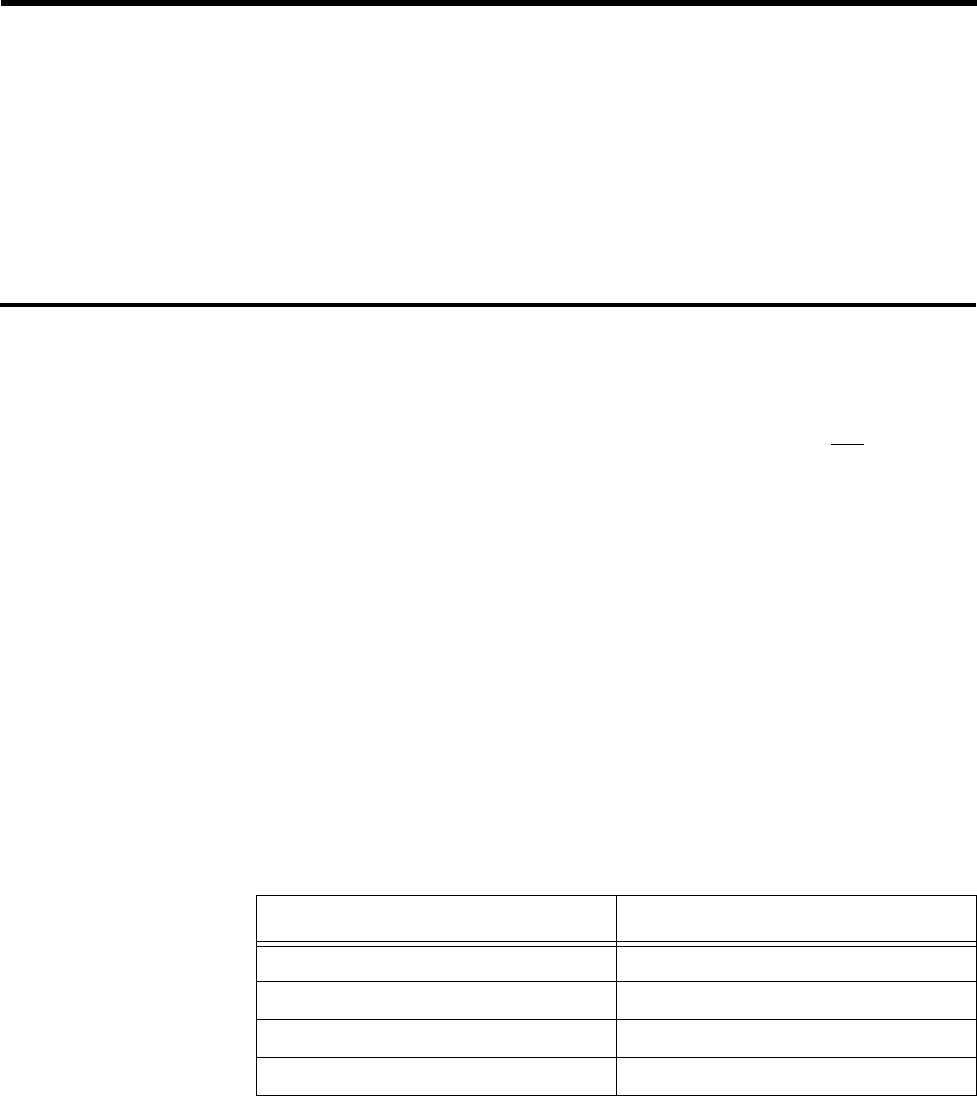
The differences between the AT-S7 and the AT-S9 are primarily physical. The
following table summarizes these differences.
Contents
The contents of each chapter are described below.
❑
Chapter 1, “Product Description” introduces an overview of
functions and features. This chapter includes information that is
common to both the AT-S7 and the AT-S9.
❑
Chapter 2, “Getting Started” describes how an experienced user can
quickly, and easily, configure an ATM network using ATI’s Omega
management software. This chapter includes information that is
specific to both the AT-S7 and the AT-S9.
❑
Chapter 3, “Ethernet Administration” tells you how to use ATI’s
Omega management Ethernet software.
❑
Chapter 4, “Software” describes several methodologies for
subsequent software support.
Document Conventions
The following conventions are used in presenting information in this manual:
Commands, prompts, and information displayed by the computer appear in
Courier typeface, for example:
Current Number of Learned Addresses: 133
Number of Defined Filters: 4
Menu selections/menu titles appear in Courier bold typeface and prove direct
access through the menus. For example, from the System Administration
submenu, enter the letters
AT
for
ATM Parameters
to access submenu
information.
AT-4016TR >
AT
AT-TS95TR >
AT
Table 1:
AT-S7/AT-S9 Characteristics
AT-4016TR/AT-4016F AT-TS95TR
AT-S7 PCMCIA Firmware Card AT-S9 Flash EPROM Cassette
16 10Base-T or Fiber Optic ports 8 10Base-T ports
No backplane 6-port segmented backplane
ATM media port is in back ATM media port is in front

AT-S7/AT-S9 Operations Manual
ix
NOTE
A note provides additional information about, or possible consequence of, a
specific action you can perform.
Related Documentation
You may find the following networking reference material helpful:
❑
Internetworking with TCP/IP: Principles, Protocols, and Architecture
(2nd
edition), Volumes I and II, Douglas Comer, Prentice Hall © 1991.
❑
Interconnections, Bridges and Routers,
Radia Perlman, Addison Wesley
© 1992.
❑
The Simple Book, An Introduction to Management of TCP/IP-based
internets
, Marshall T. Rose, Prentice Hall © Second Edition, 1994.
❑
ATM Forum contributions are only available to Principal Members of
the ATM Forum although published Forum specifications are
available for purchase. Call the ATM Forum at 415.578.6860, fax
server at 415.525.0182, or send e-mail to
af-info@atmforum.com
for details about ATM Forum membership.
❑
UNI 3.0 specifications are published by Prentice Hall and are
available at technical bookstores.
❑
Internet RFCs can be obtained through anonymous FTP or e-mail to
rfc-info@ISI.EDU
with the message:
help: ways_to_get_rfcs
❑
Internet drafts are available by anonymous FTP. Internet draft
directories are located at:
— US East Coast:
ds.internic.net
— US West Coast:
ftp.isi.edu
— Europe:
nic.nordu.net
— Pacific Rim:
nunnari.oz.au
❑
ATM documentation is also available through Phillips Publishing
International: 301.424.3700 or 703.281.1135

Preface
x
Contacting ATI Technical Support
Problems? Questions can be directed to ATI’s Technical Support staff by:
❑
Telephone
❑
Bulletin board services
❑
Electronic mail via the Internet
❑
CompuServe forum
When you contact Technical Support, you should have the following
information available:
❑
Firmware Revision number
❑
Complete description of the problem including any observed errors
❑
Complete configuration information
❑
Serial number of your ATI Switch
Phone Numbers
Commercial telephone service is available Monday through Friday from 5:00
AM to 5:00 PM PST:
1-800-428-4835
(North America)
The FAX number is:
206-481-3790
For telephone numbers outside of the United States and Canada, contact
your reseller or regional ATI office.
Bulletin Board
Services
A bulletin board is available. The number is:
206-483-7979
Modem settings for the bulletin board are: 8 bits; no parity; 1 stop bit.
The process is straightforward: Once the BBS is accessed, it requests that
you register either as a new user or as a current user. It then provides
instructions on the various features and functions available. This is followed
by a list and description of all available technical notes and files that can be
downloaded.
Internet Mail
You can send electronic mail via the Internet to:
tech_support@centre.com
CompuServe
Forum
ATI has a forum on CompuServe. You can reach us by typing
GO ALLIED
at
the CompuServe prompt (!).

AT-S7/AT-S9 Operations Manual
xi
FTP Server
Allied Telesyn provides access to an anonymous FTP Server for driver and
Readme files on our adapter cards and managed products. The server can be
accessed through your Internet connection as follows (note — use lower case
letters):
World Wide Web
You can access Allied Telesyn at our new Web Site using the following:
http://www.alliedtelesyn.com
Address gateway.centre.com [lowercase letters]
Login anonymous [lowercase letters]
Password your e-mail address [requested by the server when you login]
1
Chapter 1
Product Description
Overview
Welcome to Allied Telesyn International!
Allied Telesyn’s
AT-4016TR Ethernet Switch With ATM Access
,
AT-4016F
Ethernet Switch With ATM Access
and
AT-TS95TR TurboStack Switch With
ATM Access and Management
are all Ethernet-to-Ethernet and Ethernet-
to-ATM switches. All support 10 Mbps of
dedicated
bandwidth on 16
(AT-4016) or 8 (AT-TS95TR) IEEE 802.3 Ethernet ports. Further, all support
a 155 Mbps Asynchronous Transfer Mode (ATM) port for connectivity to an
ATM switch.
The release of system software Version 2.0 supports Ethernet and ATM
communication over Permanent Virtual Circuits (PVCs).
Your switch also provides an Emulated LAN (ELAN) capability by either
port or MAC address which, in turn, allows you to group all Ethernet ports —
as well as additional switches — as if you are in the same physical LAN.
As stated in the Preface, both switches are almost identical in form and
function. The differences are primarily physical. The following table, repeated
from the Preface, summarizes these differences.
Table 2:
AT-S7/AT-S9 Differences
AT-4016TR/AT-4016F AT-TS95TR
AT-S7 PCMCIA Firmware Card AT-S9 Flash EPROM Cassette
16 10Base-T or Fiber Optic ports 8 10Base-T ports
No backplane 6-port segmented backplane
ATM media port is in back ATM media port is in front

Product Description
2
Features
The following features are fully implemented:
❑
An Ethernet switch combined with ATM connectivity
❑
Emulated LAN support (up to 64 ELANs) user defined either by port
or MAC address
❑
Software upgrading and downloading using TFTP or the optional
PCMCIA Firmware Card (AT-S7 — Version 2.0) for the AT-4016TR
as well as the AT-4016F/SC and the AT-4016F/ST
❑
Software upgrading and downloading using TFTP or the optional
Firmware Cassette (AT-S9 — Version 2.0) for the AT-TS95TR
❑
Permanent Virtual Circuit (PVC) connectivity using LAN Emulation
headers/encapsulation
❑
ATI’s Omega software management through Telnet or a serial
connection to a RS232C port
❑
Omega management for high-level features such as administration,
statistics, status and security
❑
Support For Up To 2,048 Media Access Control (MAC) Addresses
❑
ATM Connection Management Support For Up To 128 Permanent
Virtual Circuits (PVCs) using a single Virtual Path Identifier (VPI)
❑
992 available Virtual Circuit Identifiers (VCIs)
ATI’s Solution
If your LAN is reaching the limit of its bandwidth capacity, then transition
your legacy, shared-media traffic, to a switched 10 Mbps network. Then, by
introducing ATM functionality to connect that same traffic to a server or
backbone (up to theoretically 155 Mbps in this case), bottlenecks will be
mitigated.
This value-effective approach enables you to only “upgrade” devices that
actually need the increased bandwidth (like the server).
Finally, ATI’s ATM switches are the first phase to meet both current and
future needs of your expanding networks. These services will enhance the
business environment for years to come.

AT-S7/AT-S9 Operations Manual
3
Figure 1 shows the front panel of an AT-4016TR. It is presented as a review
of the positioning of the relevant ports.
Figure 2 shows the rear panel of an AT-4016TR.
Note that, whereas this figure shows a single power supply, an optional dual,
load-sharing, power supply is available.
Figure 3 shows the front panel of an AT-TS95TR.
Figure 1:
AT-4016TR Front
Panel
RS232C Network
Management Port
PCMCIA Port
Ethernet Switch with ATM Access
1
LINK
RECEIVE
COLLISION
PCMCIA RS-232
PRESENT
FAIL
POWER SUPPLY
ALARMS 12
XXX XXXX XXXX XXX
X
MDI
MDI-X
NETWORK LOAD
1 2 3 4 5 6 7 8 9 10 11 12 13 14 15 16
2 3 4 5 6 7 8 9 10 11 12 13 14 15 16
RED YELLOW BLUE
ATM PORT
ONLINE SYNC LOS
RESET
LOOP-OUT
LOOP-IN
Figure 2:
AT-4016TR Rear
Panel
POWER SUPPLY
Ethernet Switch with ATM Access
POWER SUPPLY 1
ATM MEDIA INTERFACE AC
LOOP
INTERNAL
FAIL
FIBER SC DUPLEX
OC-3c
TIMING
SYNC LOS
ATM MEDIA INTERFACE
Figure 3: AT-TS95TR Front
Panel
ATM MEDIA INTERFACE
RS232C Network
Management Port
10Base-T Ports

Product Description
4
Figure 4 shows the rear panel of an AT-TS95TR.
Standards Compliance
The following Management Information Base (MIB) protocols are supported
by ATI’s Management Software. An expanded discussion of selected MIB
support is provided in Appendix B.
❑SNMP MIB2 (RFC 1213)
❑Ethernet MIB (RFC 1643)
❑Bridge MIB (RFC 1493)
Virtual Circuits
There are two types of Virtual Circuits:
1. Permanent Virtual Circuits (PVCs) and
2. Switched Virtual Circuits (SVCs).
A connection-oriented technology such as ATM, means that a call or virtual
connection needs to be established between at least two stations before data
can be transferred. This release presently supports Permanent Virtual
Circuits (PVCs). Switched Virtual Channels (SVCs) will be supported in a
later release.
Your switch supports up to 128 PVCs.
Figure 4: AT-TS95TR Rear
Panel
Firmware Cassette Port
Backplane

AT-S7/AT-S9 Operations Manual
5
Permanent Virtual
Circuits If connections are established manually through either network management
or remote communications, the channels are called Permanent Virtual
Circuits (PVCs). PVCs are implemented through either a management
program termed Omega or a remote management station. With this release,
each switch must have a PVC connection between itself and every other
switch.
Analogous to a leased or dedicated real circuits found in packet-based
networks, PVCs must be physically configured by a network administrator
from the ATM switch to both establish and maintain ATM connectivity.
LAN Emulation
An Emulated LAN (ELAN) allows you to configure a network through
software instead of rearranging physical cables.
ELANs are created and managed using Omega software management
screens.
Figure 5 shows a typical ATM network topology.
Figure 5: ATM Topology
Ethernet Switch with ATM Access
PCMCIA RS-232 POWER SUPPLY
ALARMS NETWORK LOAD
ATM PORT
Ethernet Switch with ATM Access
PCMCIA RS-232 POWER SUPPLY
ALARMS NETWORK LOAD
ATM PORT
Ethernet Switch with ATM Access
PCMCIA RS-232 POWER SUPPLY
ALARMS NETWORK LOAD
ATM PORT
Ethernet Switch with ATM Access
PCMCIA RS-232 POWER SUPPLYALARMS NETWORK LOADATM PORT
Ethernet Switch with ATM Access
PCMCIA RS-232 POWER SUPPLY
ALARMS NETWORK LOAD
ATM PORT
ATM
Switch
ATM inter-switch connection
Single physical link with
multiple PVCs
Server
Station 1
Station 2
“A” “B”
“C”
“D”
“E”
ATM
Switch
ATM
Switch ATM
Switch
ATM
Switch
ATM
Cloud
Server

Product Description
6
Ethernet Switching
There are two popular methods to forward information: store-and-forward
and cut-through. Although your switch employs store-and-forward as the
default, you can also choose cut-through.
Store-and-forward Store-and-forward means that your switch stores the entire packet and then
forwards it.
Store-and-forward switching, performed at the MAC layer, allows your
switch to temporarily store packets until network resources, typically a
congested port, are available. Frames which are incorrect, an invalid CRC for
example, are discarded. Store-and-forward switching, therefore, ensures data
integrity, thus preventing network error conditions from being generated
throughout the network.
Store-and-forward mode is implemented when packets are converted to cells
on each ATM transmission.
Cut-through In a cut-through system, the device starts to forward the incoming packet
while the packet is still being received on the inbound link.
Cut-through switching requires software that can both look at the start of the
packet and determine which outbound link is to be used to forward the
packet. Cut-through does not check for errors before forwarding a packet.
Bridging
Your switch operates as a transparent bridge to the Ethernet ports. As such,
it learns the source Media Access Control (MAC) addresses of all incoming
packets and ages out devices which have not been heard for a user or default
specified period of time.
The switch maintains a forwarding table with a maximum storage capacity of
2,048 MAC address. These Ethernet addresses are associated with all of the
devices that have been detected recently.
Your switch checks all incoming packets from each port for their destination
address against a Bridge Address Table. If a packet’s destination address is
not on the same network segment as the originating packet, the switch
forwards the packet to the network segment associated with that destination
address. However, if the packet’s source and destination address are on the
same network segment, known as local traffic, the packet is automatically
discarded (ignored) or filtered.
Bridge Address
Table The switch creates and maintains a dynamic database of addresses which are
stored in a Bridge Address Table. Port information entries in the Bridge
Address Table are, in turn, used as a basis from which to compare and
examine every packet to determine its source address, segment origin and
port information.

AT-S7/AT-S9 Operations Manual
7
If a packet’s MAC address is not already stored in the Bridge Address Table,
the switch adds the learned address, the associated port number and a timer
value that indicates the age of the dynamic Bridge Address Table entry.
Consequently, the switch knows the address and associated port number the
next time it sees that address. By using the information stored in the Bridge
Address Table, the switch is able to quickly forward each packet to the
correct port.
The switch learns addresses from all packets. When devices are added to the
network, removed from it, or relocated, you do not have to reconfigure your
switch. Your switch automatically learns all addresses.
An address stored in the Bridge Address Table is discarded if there is no
activity from that address after a configured length of time (the default is five
minutes). This aging process ensures that the Bridge Address Table is not
only continually updated but only includes current entries.
Each entry which is automatically entered (a dynamic entry) includes:
❑An Ethernet MAC address
❑The port number of the LAN on which the address resides
❑The age of the entry
Product Description
8

9
Chapter 2
Getting Started
A completely functional ATM network requires the successful integration of
several disparate units:
An AT-4016TR or AT-4016F Ethernet-to-ATM switch, or
An AT-TS95TR Ethernet-to-ATM switch
ATI’s Omega management software
An optional ATM-to-ATM Switch
Getting started involves the following sequence:
1. Omega management software.
Your switch is controlled by ATI’s Omega management software through
a terminal, a terminal emulator or a Telnet session.
2. Unique information.
Each switch can be assigned a unique name, location and contact
administrator.
3. Password.
Password protection is available if network security is required. The
default, of course, does not require a password.
4. ATM configuration.
ATM connectivity requires ATM address coordination between the
switch’s ATM port and an ATM switch.

Getting Started
10
Getting Started — Omega
Your switch can operate either stand-alone when the backbone port is not
connected to an ATM network — or as an Ethernet switch/ATM Emulated
LAN when the backbone port is connected to an ATM network and
functioning.
To be an operational, stand-alone Ethernet switch, your switch does not
require management (ATI’s Omega, for example) — or any other network
management application. Simply attach your devices to the RJ45 ports, apply
power and you have a working switch.
Main Menu
ATI’s Omega management software is pre-installed and operational when
power is applied to the switch. Configuring Omega depends, however, upon
the requirements of your particular environment.
Omega management enables you to access and configure your ELANs and your
switch.
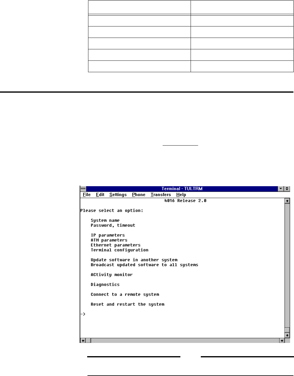
Omega’s Main menu enables you to access the submenus that are needed to
configure your Ethernet and ATM network.
The following menus are used to either view ATM statistics or configure your
ELAN:
❑Cell statistics - This menu enables you to view ATM cell transmit and
receive statistics as well as Loss of Frame and Sync Events.
❑Virtual circuit information - This menu enables you to view active VCI
information and statistics. The VCI number, name and type are listed
in this menu. You can view specific VCI statistics in a submenu.
❑LAN emulation - The Lan emulation menu enables you to access four
ELAN configuration or definition submenus.

AT-S7/AT-S9 Operations Manual
11
The Main Menu of the AT-4016F switch is shown below. The AT-TS95TR
Main Menu would be identical except for the header.
NOTE
The use of the Port, Frame, and Error statistics submenus are specifically associated
with Ethernet functionality and discussed in Chapter 4, System Administration. Since
they are not used to actually configure an ELAN, they will not be presented here.
From the Main menu you may select any of the following submenus:
❑Port status - refer to the section “Port Status” on page 45
❑Frame statistics - refer to the section “Frame Statistics” on page 63
❑Error statistics - refer to the section “Error Statistics” on page 67
❑Cell statistics - refer to the section “Cell Statistics” on page 69
❑Virtual circuit information - refer to the section “Virtual Circuit
Information” on page 38
❑System administration - refer to the section “System
Administration Menu” on page 12
❑LAN emulation- refer to the section “LAN Emulation Menu” on
page 22
❑MAC Address Table - refer to the section “MAC Address Table” on
page 40
Getting Started
12
The parameter changes noted below require the system to be reset before
they are recognized.
System Administration Menu
1. Connect the serial port of your terminal or PC to the RS232 console port
located on the front panel. For a PC connection, use a standard 9-pin serial
cable.
2. Access your terminal, or use the terminal emulator program in Microsoft
Windows.
3. Press the <RETURN> key several times. This will ensure auto configuration
of the appropriate baud rate.
4. From the Main Menu, open Omega’s System Administration
submenu by entering the letter S.
NOTE
You do not need to configure Omega if your default terminal is as follows: Data
bits: 8, Stop bits: 1, Parity: 0, Connector: Com1/Com2 (PC/terminal dependent)
Ethernet Parameters ATM Parameters
Store and Forward Sonet
Cut-Through SDH
Collision is Indicated on Amber Internal clocking LED
Transmit is Indicated on Amber External (loop) clocking LED
Unassigned cells idle cells

AT-S7/AT-S9 Operations Manual
13
System Name
From the System Administration submenu, enter the letter S for
System name to access the following submenu. This menu can be used to
enter or change the name of your switch.
You may enter a new name, up to 20 characters in length, or press RETURN to
keep the existing symbolic name. To delete an existing name, enter one or
more space characters (blanks) and then press RETURN.
NOTE
For PVC configurations, it may be helpful to make the system name and ATM
address the same.

Getting Started
14
Password,
Timeout To assign or change the password or timeout value, return to the System
Administration submenu and enter the letter P for the
Password, timeout submenu:
Password. Password protection restricts unauthorized access to Omega
management. This is a very different type of password protection than
“Download Password” which is found within the IP parameters
submenu which is discussed later. If you choose to use password protection,
the management agent prompts for the password when each new session
begins.
NOTE
The default does not have a password.
You may enter a new password, up to 32 characters in length, or just press
<RETURN> to keep the existing password if there is one. (The screen does not
display your password as you type it; a series of asterisks appears instead.)
To delete your current password, press the spacebar one or more times and
then press <RETURN>.
Timeout. Your switch allows one management session at a time. If a timeout
value is entered, then the Omega session will end when there has been no
activity on the system for the length of time specified.
Timeout may be useful to avoid connection problems due to multiple sessions
(for example, you may start a local session and not exit the system before
attempting a Telnet session later). Note that timeout will also affect the
activity monitor.

AT-S7/AT-S9 Operations Manual
15
The timeout option will automatically end the session if there is no activity
for the length of time specified (in minutes). That is, if a password timeout
value is entered the activity monitor will only run until the timeout time is
reached. The default Ø disables the timeout function.
Remember, if a switch is in session there is no access until the session is
terminated.
A session is terminated in any of three ways:
1. Timeout
2. Rebooting
3. Normal session termination using the Quit option.
Press <RETURN> for the Timeout screen.
Getting Started
16
IP Parameters
Menu From the Main menu, enter the letter S to reaccess the System
administration submenu:
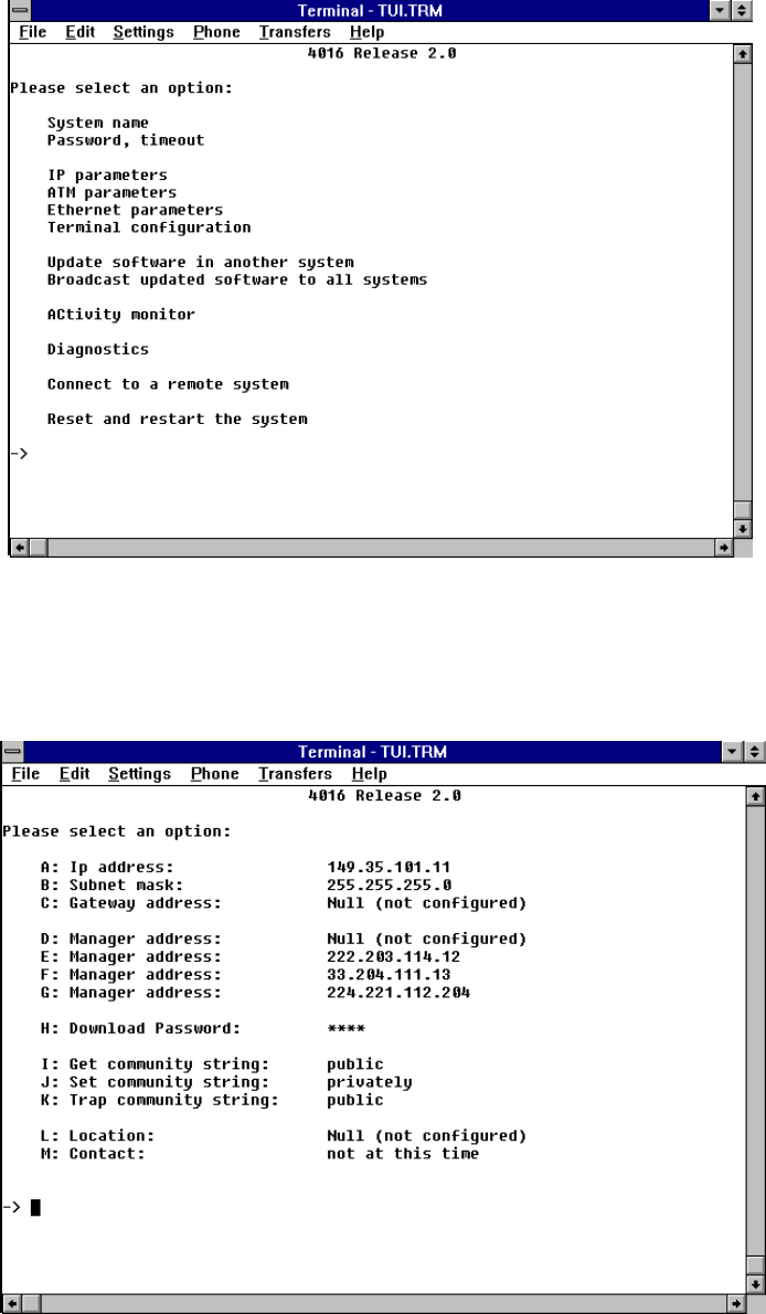
Enter the letter I for IP parameters to access the following submenu:
AT-S7/AT-S9 Operations Manual
17
A complete discussion of the parameters on this screen is contained in
Chapter 3, Ethernet Administration, and will not, therefore, be presented
here. On the other hand, the following two parameters are required to initiate
a remote network or to download software to switches which have a password
initiated.
Setting an IP Address for Telnet. Telnet requires a configured IP
Address! That is, remote communications with the switch require the use of
the Transmission Control Protocol/Internet Protocol (TCP/IP) suite. Please
refer to Chapter 3 for a discussion of the IP configuration process.
Download Password. Download password is used with TFTP commands
to download software from your switch to other switches in your network.
Download password is not associated with the password used for Omega
management.
If you change the password, ensure that you configure the same download
password for all of the switches that are to be downloaded. That is, the switch
downloading the software and the switches receiving the software must use
the same password. In short, when you use TFTP, the file name for the switch
must be the same as the downloaded password.
The process is as follows: enter the password for the hubs to be downloaded.
For example, if the current download password is ATS7 (all uppercase) then,
upon entering the command H, you will be asked “Please enter a new string,
or <RETURN> to retain the existing one.”
Please refer to Appendix A for a discussion of TFTP and how the download
password is used.

Getting Started
18
Getting Started — ATM
As stated earlier, this release provides Ethernet to ATM connectivity
through ATM Permanent Virtual Circuits (PVCs). This means that each
switch must have a PVC link between itself and any other switch. Figure 6
shows a typical ATM PVC network topology.
This configuration allows any device connected to any switch to communicate
with any other device — assuming that each device is in the same Emulated
LAN. Note that it is not necessary for every unit to be interconnected to
every other one. Only units that have devices which need to communicate
need to be connected.
Figure 6: ATM PVC Topology
Ethernet Switch with ATM Access
PCMCIA RS-232 POWER SUPPLYALARMS NETWORK LOADATM PORT
Ethernet Switch with ATM Access
PCMCIA RS-232 POWER SUPPLY
ALARMS NETWORK LOAD
ATM PORT
Ethernet Switch with ATM Access
PCMCIA RS-232 POWER SUPPLY
ALARMS NETWORK LOAD
ATM PORT
Ethernet Switch with ATM Access
PCMCIA RS-232 POWER SUPPLY
ALARMS NETWORK LOAD
ATM PORT
Ethernet Switch with ATM Access
PCMCIA RS-232 POWER SUPPLYALARMS NETWORK LOADATM PORT
ATM
Network
PVC Connections
ATM
Switch
ATM
Switch
ATM
Switch
ATM
Switch ATM
Switch
Physical Network
Single physical link
with multiple PVCs

Getting Started
20
From the System Administration submenu enter the letters AT for ATM
parameters to access the following submenu:
This submenu enables you to determine the values that regulate your ATM
network. The top part of the display shows the current values.
The following variables can be configured:
Sonet/SDH Two options are available for the Fiber Optic ATM interface: Synchronous
Optical Network (SONET) STS-3c-type framing (which is more common in
North America) and Synchronous Digital Hierarchy (SDH-1) framing (which
is more common in other countries). The default is SONET. Whichever option
you choose should remain consistent throughout the entire network.
Clocking The options are either Internal or External. Since the clock signal is normally
supplied by the ATM switch itself, the default is External (loop). Only one
switch in the network should provide clocking.
Cells The ATM specification requires the station to transmit null cells during
periods without traffic. This parameter determines whether these null cells
are either Idle or Unassigned. The default is Unassigned cells and will be
displayed within the Cell statistics submenu.

AT-S7/AT-S9 Operations Manual
21
ATM Address ATM addresses are used as a means to identify devices and to communicate
between them.
This software release allows non-standard ATM addresses. This means that
an ATM address may consist of any user-determined arbitrary numerical
designation.
Normally, an ATM address consists of a network prefix, a MAC address and a
selector byte.
[network prefix] [MAC address] [selector byte]
VPI Like traditional LAN packets, ATM cells contain addressing information.
Rather than addressing cells to specific destination devices, ATM cells are
addressed to Virtual Channels (VCs) and Virtual Paths (VPs).
Ensure that the VIP is set to zero (Ø) in the ATM parameters option within
the System Administration Menu. Ø is the only VPI that is supported at this
time.
Specifically, a Virtual Path Identifier (VPI) is a grouping of a number of
Virtual Channels. It consists of the 8-bit number in an ATM cell header which
identifies the specific virtual path that the cell is traversing in the current
physical circuit.
The switch’s connection management entity uses VCI and VPI to output
tables. Since the connections in the table are established manually through
network management or remote communications, the channels are called
Permanent Virtual Circuits (PVCs).

Getting Started
22
The VPI screen is shown below and is accessed, of course, from the System
Administration submenu.
To use the LAN emulation capabilities of ATM, you establish logical identities
for LANs, paths, channels, and MAC-addressed nodes on your network(s).
Virtual Path Identifier. The Virtual Path Identifier (VPI) for the
AT-TS95TR is set in the LAN Emulation menu (PVC definitions).
Virtual Channel Identifiers. Virtual Channel Identifiers (VCIs) are also
defined in the LAN Emulation menu (PVC definitions). There are 992 VCIs
available between 32 and 1,024 (VCIs between 1 and 31 have been reserved
for ATM management cell purposes). These are used by ATM in the cell
header to direct packets to their correct destinations. (You can also use the
LAN Emulation menu to assign ELAN membership to nodes.)
LAN Emulation Menu
This release implements multiple Emulated LANs. Although each switch can
support up to 64 Emulated LANs, each Emulated LAN requires its own PVC
between units.
Use the LAN Emulation menu to set up Emulated LANs as follows:
1. Ensure that the VPI is set to zero (Ø) in the ATM parameters option
within the System Administration Menu (Ø is the only VPI that is
supported at this time).
Once the ATM parameters are established, you are ready to configure
Emulated LANs.
AT-S7/AT-S9 Operations Manual
23
Choose LAN Emulation from the Main Menu.
NOTE
You should plan which devices should be included in an ELAN since, as you
may recall, there is no communication between ELANs without ATM routing.
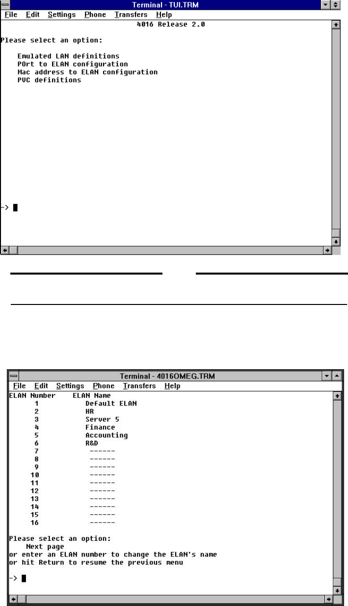
Emulated LAN
Definitions
Submenu
The Emulated LAN definitions option provides you with a list of ELAN names
that you have defined.
AT-S7/AT-S9 Operations Manual
25
By default, all devices on a port are in the same ELAN, but you can override
membership assignments for individual devices on a port. See “MAC Address
to ELAN Configuration Submenu” on page 28.
NOTE
Ensure that the management workstation remains on the same ELAN as the
management client port, Port 17. Otherwise you will lose contact with the
switch via Telnet. If you lose contact, either Telnet in from a station on the
management port’s ELAN, or initiate an Omega local session and reassign the
management station’s port to be on the same ELAN as Port 17.
To make ELAN assignments by port:
Enter po to select the Port to ELAN Configuration submenu.
The Emulated LAN column lists the ELAN that is presently configured to each port.
The Type column contains a user defined keyword to configure the port.
There are normally two keywords used:
❑MAC - If you select MAC, the MAC address defined in the MAC
address to ELAN configuration menu is used to determine ELAN
membership for a device. This is the default method for assignment of
devices to ELANs. If a device’s MAC address is not explicitly
assigned to an ELAN, it is a member of the port’s ELAN.
❑FIXED - If you choose Fixed ELAN, all devices on the port join the
port’s designated ELAN regardless of individual device assignments.
The MAC address of the device is ignored.

Getting Started
26
Select a port by typing its number listed on the left of the screen. Port 1 was
selected in this example.
On the ELAN configuration screen for the selected port, you can change the
method the switch uses to assign ELAN membership to network devices.
Choose either M for “MAC address determines ELAN; default is port’s
ELAN” or F for “Fixed ELAN: all devices on this port forced to port’s
ELAN.”

AT-S7/AT-S9 Operations Manual
27
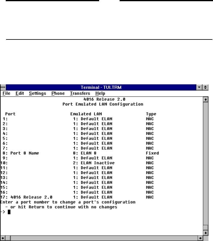
Port to ELAN Configuration Submenu AT-S9
The Port to ELAN Configuration option enables you view the ELAN name and type
of port configuration associated with each port on your switch.
This screen displays each of the eight (8) actual AT-TS95TR UTP ports as
well as the logically defined management port.
By default, all devices on a port are in the same ELAN, but you can override
membership assignments for individual devices on a port.
To make ELAN assignments by port:
Enter po to select the Port to ELAN Configuration submenu.
The Emulated LAN column lists the ELAN that is presently configured to each port.
The Type column contains a user defined keyword to configure the port. There are
normally three keywords used:
❑MAC - If you select MAC, the MAC address defined in the MAC
address to ELAN configuration menu is used to determine ELAN
membership for a device. This is the default method for assignment of
devices to ELANs. If a device’s MAC address is not explicitly
assigned to an ELAN, it is a member of the port’s ELAN.
❑FIXED - If you choose Fixed ELAN, all devices on the port join the
port’s designated ELAN regardless of individual device assignments.
The MAC address of the device is ignored.

Getting Started
28
Select a port by typing its number listed on the left of the screen. Port 9 was
selected in this example.
On the ELAN configuration screen for the selected port, you can change the
method the switch uses to assign ELAN membership to network devices.
Choose either M for “MAC address determines ELAN; default is port’s
ELAN” or F for “Fixed ELAN: all devices on this port forced to port’s
ELAN.”
MAC Address to ELAN Configuration Submenu
Once you have made port-to-ELAN membership assignments, you can assign
up to 128 MAC addresses to membership in an ELAN by selecting MAC
address to ELAN Configuration from the LAN Emulation Menu. If you do
not provide an entry for a given device in the MAC address to ELAN
configuration table, its ELAN membership is the same as the membership of
the port.
NOTE
Designating a port’s Type as Fixed on the Port to ELAN Configuration
menu overrides the individual device assignments in the MAC address to
ELAN Configuration.

AT-S7/AT-S9 Operations Manual
29
To assign ELAN membership to an individual device:
1. Enter M to select the MAC address to ELAN Configuration submenu.
2. The final screen would look similar to the following. The difference would
only consist of at least 128 possible MAC addresses:

Getting Started
30
3. Select a row in the table by typing its number listed on the left of the
screen.
Enter M to select MAC address and type in the MAC address for the device
you wish to assign to an ELAN and press <RETURN>.
AT-S7/AT-S9 Operations Manual
31
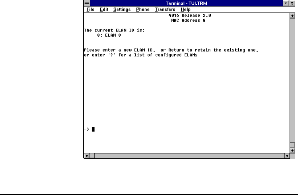
4. Enter E to select the Emulated LAN, type in the number of the ELAN you
wish to assign the device to and press <RETURN>.
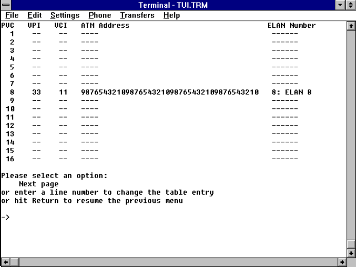
PVC Definitions Submenu
The PVC definitions menu shows the current configuration of the
Permanent Virtual Connections (PVCs).
To Configure a PVC You can add or modify PVC configurations by overwriting the entries in the
table. But first, there are four things you need to consider (and configure) in
order to set up your PVCs.
1. Determine your ATM Addresses — First, you need to define the ATM
address of the AT-4016 or AT-TS95TR you are configuring. Next, you
must determine the ATM addresses of all devices which will be attached.
To set the address, access the ATM parameters option within the
System Administration submenu. The AT-4016/AT-TS-95TR
uses this address to identify itself when communicating with other
devices. You will need to know this address in order to enable other
devices to access your system. It can be any number.
2. Define your ELAN — If you wish to use the Default ELAN (ELAN #1)
there is nothing for you to do. If, however, you are using more than one
ELAN, or you do not wish to use the Default ELAN, you must define all
new ELANs by assigning them a name.
Getting Started
32
If you need multiple ELANs, or do not use the default ELAN, you
must define an ELAN name and associate it with a number. To define
your ELAN, access the Emulated LAN Definition option within
the Main Menu. Choose the number and the name you wish to use.
3. Decide which ports (or MAC addresses) will be assigned to which ELANs.
Access the Port to ELAN Configuration submenu within the
LAN Emulation Menu to set the ELANs you would like to be
enabled on each port. By default all ports belong to ELAN 1 which is
named the “Default ELAN”.
4. Define your PVCs (up to 128 PVCs can be configured). Access the PVC
Definitions submenu within the LAN Emulation Menu.
VCI — Virtual Circuit Identifier. While you can use Virtual Circuit
Identifiers between 1 and 1,024, VCIs between 1 and 31 have been
reserved for ATM management cell purposes and are not available for
use. Further, the VCI number must be the same on each of the
switches which make up the point-to-point connection.
ATM Address — This is the ATM address of the device this PVC is
going to connect to.
VPI — Virtual Path Identifier. Accessed within the ATM
Parameters submenu within the System Administration
Menu, it must be 0 in this release.
ELAN Number — Pick the correct number of the ELAN you want
this PVC to be a member of, or use the default (Default ELAN).
The above processes can be shown in the following screens:
1. Enter PV for PVC definitions from the LAN Emulation Menu.
AT-S7/AT-S9 Operations Manual
33
NOTE
It is best to record each configuration option. This will prevent mistakes when
you configure other device.
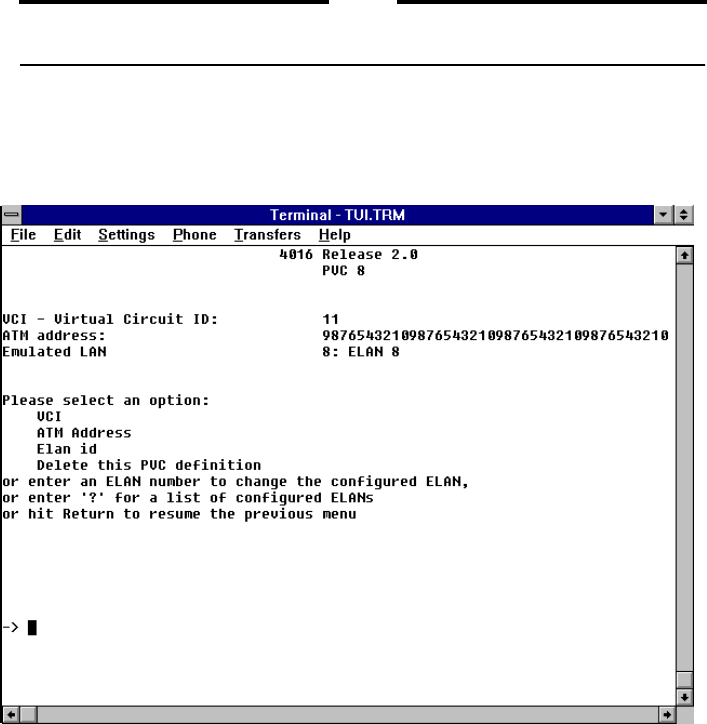
2. Select a PVC by typing its number listed on the left of the screen. The
configuration screen for the selected PVC shows the options you must
specify in order to set up a PVC.
3. Choose v for VCI, a for ATM Address, e for ELAN Number, or d to delete the
PVC definition.

Getting Started
34
VCI. If you choose VCI, the system displays the current value.
You can enter a new number to change the VCI for that particular PVC.
NOTE
While you can use Virtual Circuit Identifiers (VCIs) between 1 and 1,024,
VCIs between 1 and 31 have been reserved for ATM management cell
purposes and are not available for use. Further, the VCI number must be the
same on each of the switches which make up the point-to-point connection.

AT-S7/AT-S9 Operations Manual
35
ATM Address. The ATM address entered here is the one for the remote
system (on the far end of this PVC). It must be unique within this AT-4016.
ELAN ID. If you choose ELAN ID from the PVC Configuration Menu, you can
specify or change which Emulated LAN is associated with the PVC.

Getting Started
36
Status And Statistical Menus
Status and statistical menus are accessible from the Main menu.
NOTE
The use of the Port, Frame, and Error statistics submenus are specifically associated
with Ethernet functionality and discussed in Chapter 3, System Administration. Since
they are not used to actually configure an ELAN, they will not be presented here.
The following additional menus are used to either view ELAN statistics or
configure your ELAN:
❑Cell statistics - This menu enables you to view ATM cell transmit and
receive statistics as well as Loss of Frame and Sync Events
❑Virtual circuit information - This menu enables you to view active VCI
information and statistics. The VCI number, name and type are listed
in this menu. You can view specific VCI statistics in this submenu
❑MAC Address Table - This menu displays all MAC addresses that
have been learned and stored in the bridge filter table
AT-S7/AT-S9 Operations Manual
37
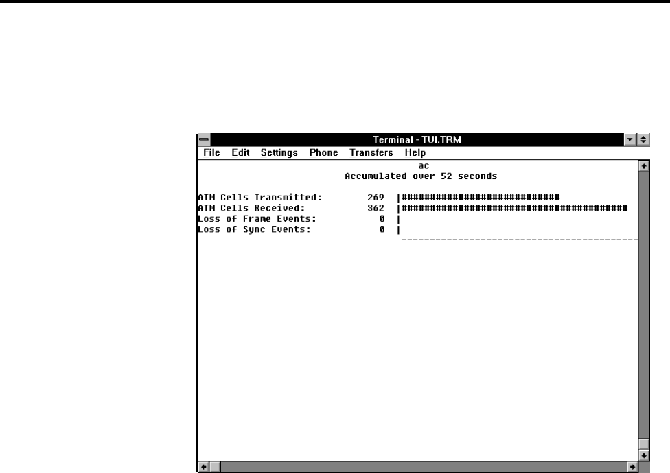
Cell Statistics Menu
The Cell Statistics menu enables you to view ATM cell transmit and receive
statistics as well as Loss of Frame and Sync events. Fields in this menu cannot
be configured.
From the Main menu, access the Cell statistics submenu.

Getting Started
38
Virtual Circuit Information
The Virtual Circuit Information (VCI) submenu enables you to view VCI statistics for
each active VCI. VCI is the 16-bit number in an ATM cell header which
identifies the specific virtual channel on which the cell is traversing on the
current physical circuit.
If you select CR, you will view all active VCIs on the network as well as data
information on each. Fields in this menu cannot be configured.
NOTE
Both the AT-S7 and AT-S9 use a VCI which has been defined as LANE-All.
From the Main menu, access the Virtual Circuit Information
submenu.
This menu provides the following information:
❑Active VCIs - All active Virtual Channel Identifier connections
associated with this switch are listed in this column.
❑Type - The type of VCI connection is listed in this column.
❑ELAN - The name of the ELAN associated with this VCI is listed in this
column.
To view additional VCI information in the VCI Statistics Menu, enter an active VCI
number and press return.

AT-S7/AT-S9 Operations Manual
39
This menu displays statistics for the VCI you specified. Again, Fields in this menu
cannot be configured.
This VCI Statistics menu provides the following information:
❑Received AAL5 Frames - The total number of AAL5 frames received by this
switch from the specified VCI
❑Received Frame Errors - The total number of frame errors received by this
switch from the specified VCI
❑Received Bytes - The total number of bytes received by this switch from the
specified VCI
❑Transmitted AAL5 Frames - The total number of AAL5 frames transmitted
from this switch to the specified VCI
❑Transmitted Frame Errors - The total number of frame errors transmitted
from this switch to the specified VCI
❑Transmitted Bytes - The total number of bytes transmitted from this switch to
the specified VCI
NOTE
All switch statistics are reset by either selecting the Zero all statistics counters on the
entire system option from any statistics menu, by selecting Restart from the Main
Menu, or by disrupting power to the switch.

Getting Started
40
MAC Address Table
Selecting the MAC Address Table menu displays all of the MAC addresses
discovered by management software on the network. From this screen you
can determine all of the MAC addresses that are available, as well as the port
or VCI, status, age, VLAN number and name for each MAC address.

41
Chapter 3
Ethernet Administration
Accessing Omega
To start a session with the management agent, either:
1. Press the <RETURN> key twice on a PC connected to the RS232 port, or
2. If your switch has been assigned an IP address, use Telnet to access the
management agent.
A session begins when either of the above events occur. Once in session, the
management agent and the Statistical Database program are “locked” against
other session requests. This prevents unwanted simultaneous access to the
database.
If you have configured a password, the management agent will require it at
the beginning of the session. If you have misplaced the password, you can
unlock the management agent by inserting the optional AT-S7 PCMCIA card
into the PCMCIA port on the AT-4016 or by inserting the optional AT-S9
Firmware Cassette into the appropriate port on the AT-TS95TR.
Selecting Menu
Options When in session, the management agent offers a series of menus. You may
select from a variety of options to view statistics or control switch activities.
❑If the options are numbered, type the appropriate number and press
the <RETURN> key
❑If the options are not numbered, type enough of the option name to
distinguish it from the other options (usually only the first letter).
That is, type the letter(s) which are capitalized; e.g., P (for Port
Status) or F (for Frame statistics).
Except for Quit, choosing a menu usually leads to a submenu which, in turn,
usually leads to yet another submenu.
You can make a choice from the present menu or return to the previous menu
by pressing RETURN or ESC.

Ethernet Administration
42
Some of the submenus cannot fit on a single screen. In this case follow the
instructions on the screen to obtain more information or to go to the next
page.
Password,
Timeout To assign or change the password or timeout value, return to the System
Administration submenu and enter the letter P for the
Password, timeout submenu:
Password. Password protection restricts unauthorized access to Omega
management. By default, there is no password. If you choose to use password
protection, the management agent prompts for the password when each new
session begins.
You may enter a new password, up to 32 characters in length, or just press
<RETURN> to keep the existing password if there is one. (The screen does not
display your password as you type it; a series of asterisks appears instead.)
To delete your current password, press the spacebar one or more times and
then press <RETURN>.
Timeout. Your switch allows one management session at a time. If a timeout
value is entered, then the Omega session will end when there has been no
activity on the system for the length of time specified.
Timeout may be useful to avoid connection problems due to multiple sessions
(for example, you may start a local session and not exit the system before
attempting a Telnet session later). Note that timeout will also affect the
activity monitor.

AT-S7/AT-S9 Operations Manual
43
Press <RETURN> for the Timeout screen.
The default, “0”, disables the timeout function.
TCP/IP
You must choose a protocol for your network: Is it to be a TCP/IP or a
nonTCP/IP network?
If you have many geographically dispersed subnetworks, each connected to
its own department concentrator, you may want to manage these multiple
switches remotely in a central-site configuration. In this case, TCP/IP
network management may be optimum.
TCP/IP internet addresses consist of user assigned numbers which identify
members of the network. It normally has two fields: network number and
host number. TCP/IP addresses are expressed in the form of a.b.c.d., where
a,b,c and d are each in the 0-254 range. For example, it adheres to the
following notation: 192.136.118.3.
In a nonTCP/IP environment, all switches and devices can be identified by
either any name convention of your choice or by a Media Access Control
(MAC) address (also known as an Ethernet address) which is assigned and
integrated into each switch by the manufacturer. TCP/IP addresses are not
required for local switch management.
Ethernet Administration
44
To Configure a
TCP/IP Address You can configure the IP Address of the switch by connecting to the serial
port of the switch and bringing up Omega or by using a BootP server. The
local installation of an IP address requires either a DOS terminal or a
Terminal Emulator Program and a serial cable.
Local Installation. Attach your terminal or PC to the RS232 serial port.
Enable Omega using either a DOS terminal or the terminal emulator program
in Windows. Then enter a TCP/IP address for each device.
The path for the appropriate TCP/IP configuration proceeds through Omega’s
Main menu and System administration submenu to the option IP
parameters. Enter the IP address as indicated.
Note that all switches have to be either configured with, or without, an IP
address. They cannot be mixed! A switch with an IP address will not respond
to a Connect remote system query from a switch which does not have an
IP address configured.
BootP You may also use a BootP server to configure TCP/IP parameters.
At start-up, if an IP address has not been configured, then your switch will
transmit a BootP request packet to the server approximately every three
seconds until a response is received (up to a maximum of three request
attempts).
If a BootP response is not received, then the system will operate with a switch
name or MAC address.
If a BootP response is received, then the IP address, Subnet Mask, and/or
Gateway/Router address will be extracted from the response packet and used
to configure the system until the next power-on/reset.
BootP server file format differs from server to server. The switches expect a
packet containing an IP address, Subnet Mask, and Gateway address.

AT-S7/AT-S9 Operations Manual
45
Port Status The Main menu of Omega is shown below.
Choose Port Status by entering the letter P. The system will then display the
AT-4016 screen shown below. Note that the AT-TS95TR screen would only
have eight (8) ports.
Produktspezifikationen
| Marke: | Allied Telesis |
| Kategorie: | Verschiedenes – Sonstiges |
| Modell: | AT-S9 |
Brauchst du Hilfe?
Wenn Sie Hilfe mit Allied Telesis AT-S9 benötigen, stellen Sie unten eine Frage und andere Benutzer werden Ihnen antworten
Bedienungsanleitung Verschiedenes – Sonstiges Allied Telesis

5 Juli 2024
5 Juli 2024
4 Juli 2024
4 Juli 2024
4 Juli 2024
3 Juli 2024
2 Juli 2024
1 Juli 2024
Bedienungsanleitung Verschiedenes – Sonstiges
- Verschiedenes – Sonstiges Samsung
- Verschiedenes – Sonstiges Apple
- Verschiedenes – Sonstiges Gembird
- Verschiedenes – Sonstiges HP
- Verschiedenes – Sonstiges Logitech
- Verschiedenes – Sonstiges Mad Catz
- Verschiedenes – Sonstiges Medion
- Verschiedenes – Sonstiges Saitek
- Verschiedenes – Sonstiges Sharkoon
- Verschiedenes – Sonstiges Roland
- Verschiedenes – Sonstiges Allnet
- Verschiedenes – Sonstiges Eminent
- Verschiedenes – Sonstiges ISY
- Verschiedenes – Sonstiges Linksys
- Verschiedenes – Sonstiges Telekom
- Verschiedenes – Sonstiges Telestar
- Verschiedenes – Sonstiges AudioSonic
- Verschiedenes – Sonstiges Fantec
- Verschiedenes – Sonstiges Pioneer
- Verschiedenes – Sonstiges TrekStor
- Verschiedenes – Sonstiges Casio
- Verschiedenes – Sonstiges Ewent
- Verschiedenes – Sonstiges Dell
- Verschiedenes – Sonstiges Power Dynamics
- Verschiedenes – Sonstiges Western Digital
- Verschiedenes – Sonstiges EnVivo
- Verschiedenes – Sonstiges Ebode
- Verschiedenes – Sonstiges Alesis
- Verschiedenes – Sonstiges Maxdata
- Verschiedenes – Sonstiges Ketron
- Verschiedenes – Sonstiges DrayTek
- Verschiedenes – Sonstiges D-Link
- Verschiedenes – Sonstiges Franklin
- Verschiedenes – Sonstiges NewStar
- Verschiedenes – Sonstiges Genexis
- Verschiedenes – Sonstiges Digitus
- Verschiedenes – Sonstiges Lancom
- Verschiedenes – Sonstiges LevelOne
- Verschiedenes – Sonstiges APC
- Verschiedenes – Sonstiges Akasa
- Verschiedenes – Sonstiges Synology
- Verschiedenes – Sonstiges EnGenius
- Verschiedenes – Sonstiges DeLOCK
- Verschiedenes – Sonstiges Griffin
- Verschiedenes – Sonstiges Konig Electronic
- Verschiedenes – Sonstiges KPN
- Verschiedenes – Sonstiges Minix
- Verschiedenes – Sonstiges Online
- Verschiedenes – Sonstiges Rion
- Verschiedenes – Sonstiges Sitecom
- Verschiedenes – Sonstiges Solcon
- Verschiedenes – Sonstiges Soundlogic
- Verschiedenes – Sonstiges Veho
- Verschiedenes – Sonstiges Wyse - Dell
- Verschiedenes – Sonstiges Zagg
Neueste Bedienungsanleitung für -Kategorien-
5 Oktober 2024
26 September 2024
22 September 2024
18 September 2024
18 September 2024
17 September 2024
16 September 2024
27 August 2024
27 August 2024
27 August 2024