Vivax HPP-24CH70AERI R32-1 Bedienungsanleitung

Vivax Wärmepumpe HPP-24CH70AERI R32-1

Lesen Sie kostenlos die 📖 deutsche Bedienungsanleitung für Vivax HPP-24CH70AERI R32-1 (56 Seiten) in der Kategorie Wärmepumpe. Dieser Bedienungsanleitung war für 17 Personen hilfreich und wurde von 2 Benutzern mit durchschnittlich 4.5 Sternen bewertet

Seite 1/56
EN
User manual
HPP 24CH70AERI R32-1-
HPP-30CH90AERI R32-1
HPP-41CH120AERI R32-1
035 23
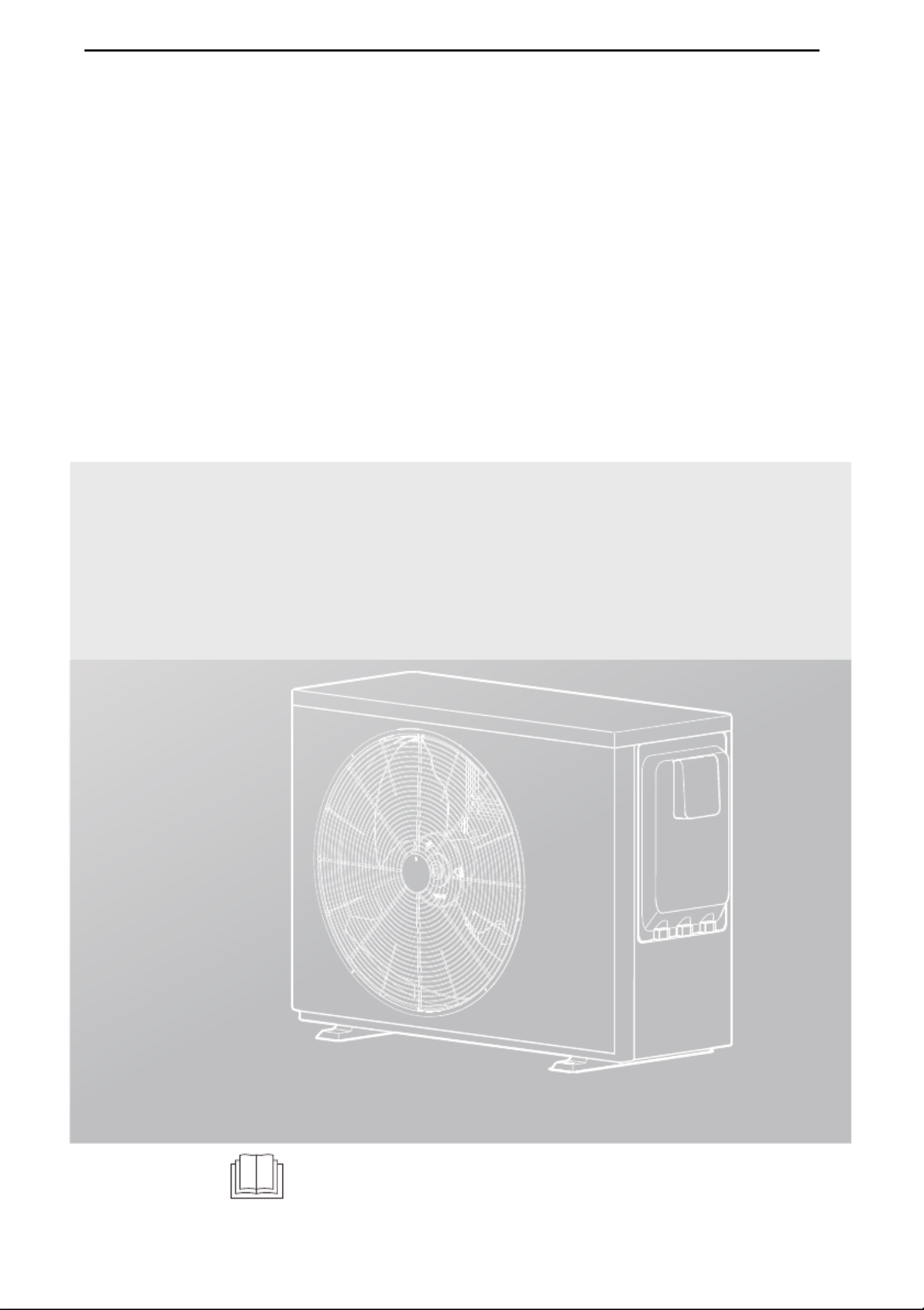
Swimming pool heat pump
INSTALLATION
AND OWNER’S MANUAL
Thank you very much for purchasing our product.
Before using your unit, please read this manual carefully and keep it for future reference.
IMPORTANT NOTE:
ENG VIVAX
CONTENTS
05
05
3
2
07
06
4
5
08
10
08
12
6
Dimensions
Shock Absorption and Fixations
Drain Hole Position
Inlet & Outlet Water Pipes
Field Wiring
Safety Device Requirement
Location Space Requirement
Location Selection In Cold Climates
Location Selection In Direct Sunlight
4.1
4.2
4.3
11
10
09
5.1
5.2
5.3
5.4
5.5
5.6
02
1
SAFETY PRECAUTIONS
ACCESSORIES SUPPLIED WITH THE UNIT
GENERAL INTRODUCTION
INSTALLATION SITE
INSTALLATION PRECAUTIONS
TYPICAL APPLICATIONS
07
RECOGNIZE THIS SYMBOL AS AN INDICATION OF IMPORTANT
SAFETY INFORMATION
WARNING
These instructions are intended as an aid to qualified licensed service personnel for proper installation, adjustment
and operation of this unit. Read these instructions thoroughly before attempting installation or operation. Failure to
follow these instructions may result in improper installation, adjustment, service or maintenance possibly resulting in
fire, electrical shock, property damage, personal injury or death.
CAUTION
Please drain water when the unit is not in use in winter to avoid freeze damage.
VIVAX ENG
7
17
8
Initial Start-up At Low Outdoor Ambient Temperature8.1
19
18Routine Maintenance
Notes For Maintenance & Repair
10.1
10.2
13
12
Refrigerant Cycle
Main Components
Inverter Drive Board
Main Control Board
Connection Of Optional Function
7.1
7.2
7.3
7.4
7.5
14
15
16
OVERVIEW OF THE UNIT
18
9
FINAL CHECKS AND TEST RUN
START-UP AND CONFIGURATION
17
17
Pre-operation Checks
Failure Diagnosis At First Installation
8.2
8.3
10
MAINTENANCE AND SERVICE
21
11
TROUBLESHOOTING
23
12
TECHNICAL SPECIFICATIONS
24
13
INFORMATION SERVICING
ENG VIVAX
NOTE
The pictures in this manual are for reference only, please refer to the actual product.
01
VIVAX ENG
Before touching electric terminal parts, turn off power switch.
When service panels are removed, live parts can be easily touched by accident.
Never leave the unit unattended during installation or servicing when the service panel is removed.
Do not touch water pipes during and immediately after operation as the pipes may be hot and could burn your
hands. To avoid injury, give the piping time to return to normal temperature or be sure to wear protective gloves.
Do not touch any switch with wet fingers. Touching a switch with wet fingers can cause electrical shock.
Before touching electrical parts, turn off all applicable power to the unit.
DANGER
Tear apart and throw away plastic packaging bags so that children will not play with them.Children playing with
plastic bags face danger of death by suffocation.
Safely dispose of packing materials such as nails and other metal or wood parts that could cause injuries.
Ask your dealer or qualified personnel to perform installation work in accordance with this manual. Do not install the
unit yourself. Improper installation could result in water leakage, electric shocks or fire.
Be sure to use only specified accessories and parts for installation work. Failure to use specified parts may result in
water leakage, electric shocks, fire, or the unit falling from its mount.
Install the unit on a foundation that can withstand its weight. Insufficient physical strength may cause the equipment
to fall and possible injury.
Perform specified installation work with full consideration of strong wind, hurricanes, or earthquakes. Improper
installation work may result in accidents due to equipment falling.
Make certain that all electrical work is carried out by qualified personnel according to the local laws and regulations
and this manual using a separate circuit. Insufficient capacity of the power supply circuit or improper electrical
construction may lead to electric shocks or fire.
Be sure to install a ground fault circuit interrupter according to local laws and regulations. Failure to install a ground
fault circuit interrupter may cause electric shocks and fire.
Make sure all wiring is secure. Use the specified wires and ensure that terminal connections or wires are protected
from water and other adverse external forces. Incomplete connection or affixing may cause a fire.
When wiring the power supply, form the wires so that the front panel can be securely fastened. If the front panel is
not in place there could be overheating of the terminals, electric shocks or fire.
After completing the installation work, check to make sure that there is no refrigerant leakage.
Never directly touch any leaking refrigerant as it could cause severe frostbite.Do not touch the refrigerant pipes
during and immediately after operation as the refrigerant pipes may be hot or cold, depending on the condition of
the refrigerant flowing through the refrigerant piping, compressor and other refrigerant cycle parts. Burns or frostbite
are possible if you touch the refrigerant pipes. To avoid injury, give the pipes time to return to normal temperature
or, if you must touch them,be sure to wear protective gloves.
Do not touch the internal parts (pump, backup heater, etc.) during and immediately after operation. Touching the
internal parts can cause burns. To avoid injury, give the internal parts time to return to normal temperature or, if you
must touch them, be sure to wear protective gloves.
WARNING
Ground the unit.
Grounding resistance should be according to local laws and regulations.
Do not connect the ground wire to gas or water pipes, lightning conductors or telephone ground wires.
Incomplete grounding may cause electric shocks.
- Gas pipes Fire or an explosion might occur if the gas leaks.
- Water pipes Hard vinyl tubes are not effective grounds.
- Lightning conductors or telephone ground wiresElectrical threshold may rise abnormally if struck by a lightning
bolt.
Install the power wire at least 3 feet (1 meter) away from televisions or radios to prevent interference or noise.
(Depending on the radio waves, a distance of 3 feet (1 meter) may not be sufficient to eliminate the noise.)
Do not wash the unit. This may cause electric shocks or fire. The appliance must be installed in accordance with
national wiring regulations. If the supply cord is damaged, it must be replaced by the manufacturer, its service agent
or similarly qualified persons in order to avoid a hazard.
CAUTION
03
VIVAX ENG
2 GENERAL INTRODUCTION
These units are used for both heating and cooling the water of swimming pool, they can keep the pool water temperature
stable at the set temperature to provide comfortable swimming condition in different seasons.
A wired controller is supplied with the unit.
NOTE
Maximum length of communication wirings between the unit and the controller is 20m.
Power cords and communication wires must be laid out separately, they can not be placed in the same conduit.
Otherwise, it may lead to electromagnetic interference. Power cords and communication wires should not come in
contact with the refrigerant pipe so as to prevent the high temperature pipe from damaging wires.
Communication wires must use shielded lines.
Operation range
-10 -7 0 5 10 15 20 30 40 43 50
40
30
20
10
0
Ambient temperature
đ
Water inlet Temperatuređ
-10 0 10 15 20 30 35 40 43 50
40
30
20
0
Ambient temperature
đ
Water inlet Temperatuređ
3 ACCESSORIES SUPPLIED WITH THE UNIT
Installation & owner’s manual
(this book)
Quantity
Installation & owner’s manual
Wired controller
Loose joint
ShapeName
1
1
2
Wired controller
1
1
Drain connection
05
Heating mode operation range Cooling mode operation range
12
10
VIVAX ENG
4 INSTALLATION SITE
When installing the unit in a place exposed to strong wind, pay special attention to the following.
There is flammable refrigerant in the unit and it should be installed in a well-ventilated site. If the unit is installed
inside, an additional refrigerant detection device and ventilation equipment must be added in accordance with the
standard EN378. Be sure to adopt adequate measures to prevent the unit from being used as a shelter by small
animals.
Small animals making contact with electrical parts can cause malfunction, smoke or fire. Please instruct the
customer to keep the area around the unit clean.
WARNING
Select an installation site where the following condtions are satisfied and one that meets with your customer's approval.
Places that are well-ventilated.
Places where the unit does not disturb neighbors.
Safe places which can bear the unit's weight and vibration and where the unit can be installed at an even level.
Places where there is no possibility of flammable gas or product leak.
The equipment is not intended for use in a potentially explosive atmosphere.
Places where servicing space can be well ensured.
Places where the units' piping and wiring lengths come within the allowable ranges.
Places where water leaking from the unit cannot cause damage to the location (e.g. in case of a blocked drain pipe).
Places where rain can be avoided as much as possible.
Do not install the unit in places often used as a work space. In case of construction work (e.g. grinding etc.) where a
lot of dust is created, the unit must be covered.
Do not place any object or equipment on top of the unit (top plate).
Do not climb, sit or stand on top of the unit.
Be sure that sufficient precautions are taken in case of refrigerant leakage according to relevant local laws and
regulations.
Don’t install the unit near the sea or where there is corrosion gas.
Strong winds of 5 m/sec or more blowing against the unit's air outlet causes a short circuit (suction of discharge air),
and this may have the following consequences:
Deterioration of the operational capacity.
Frequent frost acceleration in heating operation.
Disruption of operation due to rise of high pressure.
When a strong wind blows continuously on the front of the unit, the fan can start rotating very fast until it breaks.
06

500

 


Rubber shocking
proof mat
Solid foundation
unit:mm
4.1 Location Space Requirement
ENG VIVAX
To prevent exposure to wind, install the unit with its suction side facing the wall.
Never install the unit at a site where the suction side may be exposed directly to wind.
To prevent exposure to wind, install a baffle plate on the air discharge side of the unit.
In heavy snowfall areas, it is very important to select an installation site where the snow will not affect the unit. If
lateral snowfall is possible, make sure that the heat exchanger coil is not affected by the snow (if necessary
construct a lateral canopy).
Make sure there is enough space to install the unit.
Set the outlet side at a right angle to the direction of the wind.
Mount the unit on the foundation of concrete blocks to drain waste water from around the unit.
If you install the unit on a frame, please install a waterproof plate on the underside of the unit to prevent water from
coming in from the low side.
When installing the unit in a place frequently exposed to snow, pay special attention to elevate the foundation as high as
possible.
As the outdoor temperature is measured via the unit's ambient temperature sensor, make sure to install the unit in the shade or
under a canopy to avoid direct sunlight, so that it is not influenced by the sun’s heat, otherwise the unit may be protected.
4.2 Location Selection In Cold Climates
4.3 Location Selection In Direct Sunlight
NOTE
When operating the unit in cold climates, be sure to follow the instructions described below.
ķ
ĸ
ķ Construct a large canopy.
ĸ Construct a pedestal.
Install the unit high enough off the ground to prevent
it from being buried in snow. (The height of the
pedestal must be larger than the largest thickness of
the snow in the local history plus 10cm or more)
07
VIVAX ENG
5.1 Dimensions
5 INSTALLATION PRECAUTIONS
Model: 70/90/120
Unit: mm
5.2 Shock absorption and fixations
Check the strength and levelness of the installation floor, ensure that the vibration and noise of the unit are minimized.
Bolts, nuts, gaskets, shock pads, foundations are not provided, please purchase or contact the installer.
08
93 426
121 663
365 915
988
110
375
712
310
5.2.1 Install with bolt shock pad
20-25
30
Bolt: M8*20-25
Rubber: diameter 30
2-G1.5"
DN50
QuantityNameItem Specification
Bolt shock pad 4
4
Nut M8
4
Gasket M8
ENG VIVAX
5.3 Drain Hole Position
09
Drain hole
Drain hole
QuantityNameItem Specification
Perforated shock pad 4
4
2
Nut M8
4Bolt M8
External diameter 30
,QQHUGLDPHWHU
Solid foundation W*H*L: 100*100*500
20-25
1 2
3 4
30
5.2.1 Install with perforated shock pad and bolts
For collecting the condensed water and discharging it centrally, please connect the unit's drain hole to drain hose (30mm)
by using the Drain Connection which included in the accessory.
Drain connection
Connect to drain hose 31mm
4Gasket M8
VIVAX ENG
5.4 Inlet & Outlet Water Pipes
5.5 Field Wiring
10
Junction box
water outlet
water inlet
L N
LPS
FUSE
UNIT POWER SUPPLY
1-phase
Loose joint
The ground fault circuit interrupter must be 1 high-speed type of 30mA(<0.1s).
Stated values are maximum values (see electrical data for exact values).
Leakage protection switch must be installed to the power supply of the unit.
Equipment must be grounded.
All high-voltage external load, if it is metal or a grounded port, must be grounded.
For installation and connection
of the wired controller, please
refer to the Installation &
owner’s manual of Wired
controller.
ENG VIVAX
11
Rated current
of appliance:( )A
Nominal cross-sectional area (mm )
2
Flexible cords Cable for fixed wiring
3
> 63 and
>6 and 10
>10 and 16
>16 and 25
>25 and 32
>32 and 50
>50 and 63
0.5 and 0.75
0.75 and 1
1 and 1.5
1.5 and 2.5
2.5 and 4
4 and 6
6 and 10
10 16 and
1 to 2.5
1 to 2.5
1 to 2.5
1.5 to 4
2.5 to 6
4 to 10
6 to 16
10 to 25
1. For each unit, select the wire diameters according to the Wire select table and select breaker according to the MFA value
of Breaker select table. In case the MCA exceeds 63A, the wire diameters should be selected according to the national
wiring regulation.
2. For 3 phase units, maximum allowable voltage range variation between phases is 2% .
3. Select circuit breaker that having a contact separation in all poles not less than 3 mm providing full disconnection, where
MFA is used to select the current circuit breakers and residual current operation breakers.
Wire select table
Breaker select table
NOTE
5.6 Safety Device Requirement
Model
70
90
120
Power supply Fan motor
FLA (A)FLA (A) kW
Compressor
Power current
Voltage (V) Hz MCA (A) TOCA (A) MFA (A) MSC (A)
220-240
220-240
220-240
MCA : Minimum. Circuit Amps. (A)
TOCA : Total Over-current Amps. (A)
MFA : Max. Fuse Amps. (A)
MSC : Max. Starting Amps. (A)
RLA : In nominal cooling or heating test conditionthe input Amps of compressor where MAX. Hz can operate
Rated Load Amps. (A)
kW : Rated Motor Output
FLA : Full Load Amps. (A)
50
50
50
10.5
11
12
14
14
14
16
16
16
0.05
0.08
0.11
0.4
0.5
0.7
-
-
-
6.8
9.3
10.0
: Copper wire
Proper power wiring connections
When connecting to the power supply terminal, use the circular wiring terminal with the insulation casing (see Figure 1).
If circular wiring terminal with the insulation casing cannot be used, please make sure that:
Do not connect two power cords with different diameters to the same power supply terminal (may cause overheating
of wires due to loose wiring) (See Figure 2).
Use power cord that conforms to the specifications and connect the power cord firmly. To prevent the cord from being
pulled out by external force, make sure it is fixed securely.
+Power cord
Insulation tube
Circular wiring
terminal
Figure 1 Figure 2
VIVAX ENG
6 TYPICAL APPLICATIONS
7 OVERVIEW OF THE UNIT
Installation items:
All the items except the heat pump in the illustration are not supplied,
please purchase or contact the installer.
Cooling
Heating
Water outlet
Water inlet
4
8
9
14
17
12
10
11 13
19
18
15
16
7
5
6
3
2
1
12
Chlorinator cellWater outlet
Water inlet Sand filter
Water pump
Pool
Valve
Water supply
(or other filter)
7.1 Refrigerant Cycle
NOTE
Please follow these steps when using for the first time
1.Open valve and charge water.
2.Make sure that the pump and the water-inlet pipe have been filled with water.
3.Close the valve and start the unit.
Attention: It is necessary that the water-inlet pipe is higher than the pool surface.
The schematic diagram is for reference only. Please check the water inlet/outlet label on the heat pump while
plumbing installation.
ENG VIVAX
Item Description Item Description
1
2
3
4
5
6
7
8
10
9
Compressor
Discharge temperature sensor
High pressure switch
Suction temperature sensor
Low pressure switch
4-way valve
Fin-coil heat exchanger
Ambient temperature sensor
Coil temperature sensor
DC-fan
Electronic expansion valve
Filter
Filter
Titanium heat exchanger
Gas refrigerant temperature sensor
Liquid refrigerant temperature sensor
Water outlet temperature sensor
Water inlet temperature sensor
Water flow switch
11
12
13
14
15
16
17
18
19
13
7.2 Main Components
Fan blade Fan motor
Inverter drive board
Main control board
Titanium heat exchanger
Compressor
VIVAX ENG
14
7.3 Inverter Drive Board
4-way Valve
Flow switch
Electronic expansion valve
1 2 3
CN32
CN2
CN13
CN10
CN1
4
5
8 67
1
2
3
4
Assembly unit Assembly unitCode Code
5
6
7
8
Port for fan(CN32)
Compressor connection port U
Compressor connection port V
Compressor connection port W
Port for communication with main control board (CN10)
Input port L for rectifier bridge(CN1)
Input port N for rectifier bridge(CN2)
Power supply port to Main control board(CN13)
ENG VIVAX
15
7.4 Main Control Board
Assembly unit Assembly unitCode
23
24
25
26
27
28
29
30
31
32
Port for communication with Inverter module
(CN43)
Port for flow switch(CN16)
Port for high pressure switch (CN18)
Port for flow remote switch((CN15) Reserved(CN19)
Reserved(CN42)
Reserved(CN41)
Port for high pressure sensor(CN3) (Reserved)
Port for TL temperature sensor(CN7) (Reserved)
Port for communication with wire controller PQE
(CN11)
Port for transformer output(CN28)
33
34
35
36
37
1
2
3
4
5
6
7
8
9
Code
12
11
10
15
16
17
18
19
14
13
Power input port from Main control board (CN1) 20
21
22
Port for low pressure switch (CN17)
Port for communication with ammeter(CN22)
(Reserved)
16
37
28
30
29
31
18192021
26
23 22
24
25
27
35
34
33
36
1 2
17
3 4 5
14
15
10
11
12
13
6 7 8 9
Port for communication with wire controller AB (CN29)
Port for communication with outdoor unit (CN20)
(Reserved)
Port for electrical expansion valve1(CN33)
Port for TH temp.sensor(CN5)
Port for TP temp.sensor(CN4)
Port for T2,T2B,TW-in,TW-out temp.sensor(CN10)
Port for T3,T4 temp.sensor(CN6)
Port for EEV3/SG EVU(CN23)
temperature sensor(CN9) (Reserved)
temperature sensor(CN8) (Reserved)
Reserved (CN37)
Port for transformer input(CN40)
Dip switch S1
Digital display(DSP1)
Dip switch S5
Dip switch S6
Port for PUMP(CN39)
Port for 4-way valve(CN36)
Port for plate heater(CN35)
Reserved(CN38)
Port for point check(SW2)
Port for forced cooling(SW1)
Dip switch S7(Reserved)
POWER-IOUT1
H-SEN
P E Q
COMM
S6
32
S6
on/off
FS
CN16
AC 12VTRANS OUT
CN28 CN29CN19
X Y E
T9O
CN9
T9I
CN8
EEV3/SG EVU
CN23
T2
T2B
TWin
TWout
CN10
VIVAX ENG
16
7.5 Connection Of Optional Function
1) SG=ON, EVU=ON.
If the heat pump in heating mode:
Ɣ7KHKHDWSXPSDXWRPDWLFDOO\DFWLYDWHVWKHERRVWIXQFWLRQ
2) SG=OFF, EVU=ON.
If the heat pump in heating mode:
Ɣ7KHKHDWSXPSDXWRPDWLFDOO\DFWLYDWHVWKHERRVWIXQFWLRQ
3) SG=ON, EVU=OFF.
The unit will operate normally.
4) SG=OFF, EVU=OFF.
The maximum running hours of the compressor does not
exceed the parameter of SMART GRID RUNNING TIME.
SMART GRID RUNNING TIME initial value is 2, range 0-255.
Wiring size(mm2) 0.75
2) For outside pump :
Power supply
7 5 3 1 A1
A2
2468
72
Main
control board
/ 1
XT3
1) For smart grid:
3) For remote switch
The unit has smart grid function, there are two ports on
PCB to connect SG signal and EVU signal as following:
SMART GRID
XT2
6* (98
72
Main
control board
on/off
remote switch=closed, heat pump=OFF.
remote switch=opened, heat pump=ON.
Water pump
6* (98
ENG VIVAX
8 START-UP AND CONFIGURATION
The unit should be configured by the installer to match the installation environment (outdoor climate, installed options, etc.)
and user expertise.
It is important that all information in this chapter is read sequentially by the installer and that the system is configured
as applicable.
CAUTION
Checks before initial start-up.
8.2 Pre-operation Checks
8.3 Failure Diagnosis At First Installation
During initial start-up and when water temperature is low, it is important that the water is heated gradually.
8.1 Initial Start-up At Low Outdoor Ambient Temperature
DANGER
Switch off the power supply before making any connections.
After the installation of the unit, check the following before switching on the circuit breaker:
Field wiringMake sure that the field wiring between the local supply panel and unit and valves (when applicable)
have been connected according to the wiring diagrams and to local laws and regulations.
Fuses, circuit breakers, or protection devices Check that the fuses or the locally installed protection devices are of
the size and type specified in “TECHNICAL SPECIFICATIONS”.
Make sure that no fuses or protection devices have been bypassed.
Ground wiringMake sure that the ground wires have been connected properly and that the ground terminals are
tightened.
Internal wiring Visually check the switch box for loose connections or damaged electrical components.
MountingCheck that the unit is properly mounted, to avoid abnormal noises and vibrations when starting up the
unit.
Damaged equipmentCheck the inside of the unit for damaged components or squeezed pipes.
Refrigerant leakCheck the inside of the unit for refrigerant leakage. If there is a refrigerant leak, call your local
dealer.
Power supply voltageCheck the power supply voltage on the local supply panel. The voltage must correspond to
the voltage on the identification label of the unit.
Shut-off valves Make sure that the shut-off valves are fully open.
If nothing is displayed on the user interface, it is necessary to check for any of the following abnormalities before diagnosing
possible error codes.
-Disconnection or wiring error (between power supply and unit and between unit and user interface).
-The fuse on the PCB may be broken.
If the user interface shows "E8" or "E0" as an error code, there is a possibility that there is air in the system, or the water level
in the system is less than the required minimum.
If the error code E2 is displayed on the user interface, check the wiring between the user interface and unit.
More error code and failure causes can be found in 12 "Error codes".
17
VIVAX ENG
Final checks
9 FINAL CHECKS AND TEST RUN
10 MAINTENANCE AND SERVICE
The installer is obliged to verify correct operation of unit after installation
Before switching on the unit, read following recommendations:
When the installation and parameter setting are completed, cover all the sheet metal of the unit well.
The unit should be maintained by professionals
In order to ensure optimal availability of the unit, a number of checks and inspections on the unit and the field wiring have to
be carried out at regular intervals
This maintenance needs to be carried out by your local technician.
Before carrying out any maintenance or repairing activity, must switch off the power supply on the supply panel.
Do not touch any live part for 10 minutes after the power supply is turned off.
The crank heater of compressor may operate even in standby.
Please note that some sections of the electric component box are hot.
Forbid touch any conductive parts.
Forbid rinse the unit. It may cause electric shock or fire.
Forbid leave the unit unattended when service panel is removed.
Refrigerant supplement:
-Each unit has been equipped with sufficient refrigerant when leaving the factory. Do not charge or change the
refrigerant.If you need to replenish the refrigerant due to leakage, please contact the engineer or dealer .
Do not change the system parameters before consulting the engineer.
Ensure the waterways are clean and avoid dirt and blockage.
Please usethe parts provided or recommended by the company, do not use the parts unqualified.
DANGER
18
Thoroughly inspect and clean up the unit.
Water filter
-Clean the waterway system.
-Clean the water filter.
-Check water pump, regulating valve and other waterway equipment.
Unit switch box
-Carry out a thorough visual inspection of the switch box and look for obvious defects such as loose connections or defective
wiring.
-Check for correct operation of contactors with an ohm meter. All contacts of these contactors must be in open position.
Winter antifreeze
-If the unit is not operation in winter, remove the inlet and outlet water connections and let off the water of the unit.
The following checks must be performed at least once a year by qualified person.
10.1 Routine Maintenance
ENG VIVAX
19
10.2 Notes For Maintenance & Repair
10.2.1 Top panel remove
10.2.2 Titanium heat exchanger replace
The titanium heat exchanger’s remove and installation
can only by loosening the copper tube at the top (use
welding torch).
Do not repair or replace heat exchangers by
unscrewing nuts. This operation will damage the
sealing surface of the nut and cause refrigerant
leakage.
WARNING
Junction box
M4 screw*2
Unscrew these
2 screws
before remove
the top panel
VIVAX ENG
20
10.2.3 Inverter drive board replace
Remove the connecting
wires from the inverter
drive board before taking it
out if necessary
1 2
3 4
5 6
ENG VIVAX
NO.
1. Restart the unit.
2. Power off the unit,unplug and plug the cable of display, and then power on.
3. If all the above checks are ok, the fault still exists, please contact the installer
or retailer.
Error
code Solutions
Common malfunctions/protections and solutions in heating mode
Communication failure
Water flow protection
High pressure
protection
Low pressure
protection
1. Check whether the water pump works properly.
2. Check whether there is no water flow or water flow is too low.
3. If all the above checks are ok, the fault still exists, please contact the installer
or retailer.
1. Check whether the water pump works properly.
2. Check whether there is no water flow or water flow is too low.
3. If all the above checks are ok, the fault still exists, please contact the installer
or retailer.
1. Check whether the water pump works properly.
2. Check whether there is no water flow or water flow is too low.
3. If all the above checks are ok, the fault still exists, please contact the installer
or retailer.
1. Check whether the fan is running properly.
2. Check whether the finned heat exchanger and air outlet of the unit are
blocked by debris.
3. If all the above checks are ok, the fault still exists, please contact the installer
or retailer.
1. Check whether the ambient temperature is lower than the operating range of
the unit.
2. Check whether the finned heat exchanger and air outlet of the unit are
blocked by debris.
3. Check whether the ambient temperature probe is detached or attached to the
fin.
4. If all the above checks are ok, the fault still exists, please contact the installer
or retailer.
Ambient temp. Out of
operation range
The temperature
difference between
inlet and outlet is too
large
Malfunction / protection
E2
E8
P5
bA
P1
P0
1
2
3
4
5
6
22
ENG VIVAX
13 INFORMATION SERVICING
1) Checks to the area
Prior to beginning work on systems containing flammable refrigerants, safety checks are necessary to ensure that the
risk of ignition is minmised. For repair to the refrigerating system, the following precautions shall be complied with prior
to conducting work on the system.
2) Work procedure
Works shall be undertaken under a controlled procedure so as to minimise the risk of a flammable gas or vapour being
present while the work is being performed.
3) General work area
All mintenance staff and others working in the local area shall be instructed on the nature of work being carried out.
work in confined sapces shall be avoided. The area around the work space shall be sectioned off. Ensure that the
conditions within the area have been made safe by control of flammable material.
4) Checking for presence of refrigerant
The area shall be checked with an appropriate refrigerant detector prior to and during work, to ensure the technician is
aware of potentially flammable atmospheres. Ensure that the leak detection equipment being used is suitable for use
with flammable refrigerants, i.e. no sparking, adequately sealed or intrinsically safe.
5) Presence of fire extinguisher
If any hot work is to be conducted on the refrigeration equipment or any associated parts, appropriate fire extinguishing
equipment shall be available to hand. Have a dry power or CO2 fire extinguisher adjacent to the charging area.
6) No ignition sources
No person carrying out work in relation to a refrigeration system which involves exposing any pipe work that contains or
has contained flammable refrigerant shall use any sources of ignition in such a manner that it may lead to the risk of
fire or explosion.
All possible ignition sources, including cigarette smoking, should be kept sufficiently far away from the site of
installation, repairing, removing and disposal, during which flammable refrigerant can possibly be released to the
surrounding space. Prior to work taking place, the area around the equipment is to be surveyed to make sure that there
are no flammable hazards or ignition risks. NO SMOKING signs shall be displayed.
7) Ventilated area
Ensure that the area is in the open or that it it adequately ventilated before breaking into the system or conducting any
hot work.
A degree of ventilation shall continue during the period that the work is carried out. The ventilation should safely
disperse any released refrigerant and preferably expel it externally into the atmosphere.
8) Checks to the refrigeration equipment
Where electrical components are being changed, they shall be fit for the purpose and to the correct specification. At all
times the manufacturer s maintenance and service guidelines shall be followed. If in doubt consult the manufacturer s
technical department for assistance. The following checks shall be applied to installations using flammable refrigerants.
9) Checks to electrical devices
Repair and maintenance to electrical components shall include initial safety checks and component inspection
procedures. If a fault exists that could compromise safety, then no electrical supply shall be connected to the circuit
until it is satisfactorily dealt with. If the fault cannot be corrected immediately but it is necessary to continue operation,
and adequate temporary solution shall be used. This shall be reported to the owner of the equipment so all parties are
advised.
Initial safety checks shall include:
The charge size is in accordance with the room size within which the refrigerant containing parts are installed.
The ventilation machinery and outlets are operating adequately and are not obstructed.
If an indirect refrigerating circuit is being used, the secondary circuits shall be checked for the presence of refrigerant;
marking to the equipment continues to be visible and legible.
Marking and signs that are illegible shall be corrected.
Refrigeration pipe or components are installed in a position where they are unlikely to be exposed to any substance
which may corrode refrigerant containing components, unless the components are constructed of materials which are
inherently resistant to being corroded or are suitably protected against being so corroded.
That capacitors are discharged: this shall be done in a safe manner to avoid possibility of sparking.
That there no live electrical components and wiring are exposed while charging, recovering or purging the system.
That there is continuity of earth bonding.
10) Repairs to sealed components
Ensure that apparatus is mounted securely.
Ensure that seals or sealing materials have not degraded such that they no longer serve the purpose of preventing the
ingress of flammable atmospheres. Replacement parts shall be in accordance with the manufacturer s specifications.
24
ENG VIVAX
11) Repair to intrinsically safe components
Do not apply any permanent inductive or capacitance loads to the circuit without ensuring that this will not exceed the
permissible voltage and current permitted for the equipment in use. Intrinscially safe components are the only types
that can be worked on while live in the presence of a flammable atmosphere. The test apparatus shall be at the correct
rating. Replace components only with parts specified by the manufacturer. Other parts may result in the ignition of
refrigerant in the atmosphere from a leak.
12) Cabling
Check that cabling will not be subject to wear, corrosion, excessive pressure, vibration, sharp edges or any other
adverse environmental effects. The check shall also take into account the effects of aging or continual vibration from
sources such as compressors or fans.
13) Detection of flammable refrigerants
Under no circumstances shall potential sources of ignition be used in the searching for or detection of refrigerant leaks.
A halide torch (or any other detector using a naked flame) shall not be used.
14) Leak detection methods
The following leak detection methods are deemed acceptable for systems containing flammable refrigerants. Electronic
leak detectors shall be used to detect flammable refrigerants, but the sensitivity may not be adequate, or may need
re-calibration.(Detection equipment shall be calibrated in a refrigerant-free area.) Ensure that the detector is not a
potential source of ignition and is suitable for the refrigerant. Leak detection equipment shall be set at a percentage of
the LFL of the refrigerant and shall be calibrated to the refrigerant employed and the appropriate percentage of gas
(25% maximum) is confirmed. Leak detection fluids are suitable for use with most refrigerants but the use of detergents
containing chlorine shall be avoided as the chlorine may react with the refrigerant and corrode the copper pipe-work. If
a leak is suspected ,all naked flames shall be removed or extinguished. If a leakage of refrigernat is found which
requires brazing, all of the refrigerant shall be recovered from the system, or isolated(by means of shut off valves) in a
part of the system remote from the leak . Oxygen free nitrogen(OFN) shall then be purged through the system both
before and during the brazing process.
15) Removal and evacuation
When breaking into the refrigerant circuit to make repairs of for any other purpose conventional procedures shall be
used, However, it is important that best practice is followed since flammability is a consideration. The following
procedure shall be adhered to:
Remove refrigerant;
Purge the circuit with inert gas;
Evacuate;
Purge again with inert gas;
Open the circuit by cutting or brazing.
The use of silicon sealant may inhibit the effectiveness of some types of leak detection equipment. Instrinsically safe
components do not have to be isolated prior to working on them.
NOTE
The refrigerant charge shall be recovered into the correct recovery cylinders. The system shall be flushed with OFN to
render the unit safe. This process may need to be repeated several times.
Compressed air or oxygen shall not be used for this task.
Flushing shall be achieved by breaking the vacuum in the system with OFN and continuing to fill until the working
pressure is achieved, then venting to atmosphere, and finally pulling down to a vacuum. This process shall be repeated
until no refrigerant is within the system.
When the final OFN charge is used, the system shall be vented down to atmospheric pressure to enable work to take
place.
This operation is absolutely vital if brazing operations on the pipe-work are to take place.
Ensure that the outlet for the vacuum pump is not closed to any ignition sources and there is ventilation available.
16) Charging procedures
In addition to conventional charging procedures, the following requirements shall be followed:
Ensure that contamination of different refrigerants does not occur when using charging equipment. Hoses or lines shall
be as short as possible to minimize the amount of refrigerant contained in them.
Cylinders shall be kept upright.
Ensure that the refrigeration system is earthed prior to charging the system with refrigerant.
Label the system when charging is complete(if not already).
Extreme care shall be taken not to overfill the refrigeration system.
Prior to recharging the system it shall be pressure tested with OFN. The system shall be leak tested on completion of
charging but prior to commissioning. A follow up leak test shall be carried out prior to leaving the site.
25
VIVAX ENG


Produktspezifikationen

Marke: Vivax
Kategorie: Wärmepumpe
Modell: HPP-24CH70AERI R32-1

Brauchst du Hilfe?

Wenn Sie Hilfe mit Vivax HPP-24CH70AERI R32-1 benötigen, stellen Sie unten eine Frage und andere Benutzer werden Ihnen antworten


Bedienungsanleitung Wärmepumpe Vivax

Bedienungsanleitung Wärmepumpe

Neueste Bedienungsanleitung für -Kategorien-