Sound Devices A20-Nexus Bedienungsanleitung
Sound Devices
Empfänger
A20-Nexus
Lesen Sie kostenlos die 📖 deutsche Bedienungsanleitung für Sound Devices A20-Nexus (76 Seiten) in der Kategorie Empfänger. Dieser Bedienungsanleitung war für 50 Personen hilfreich und wurde von 2 Benutzern mit durchschnittlich 4.5 Sternen bewertet
Seite 1/76
ASTRAL®
A20-Nexus
8-, 12-, and 16-Channel, True-Diversity Receiver
with SpectraBand Technology
User Guide v1.60

Table of Contents
Welcome to the A20-Nexus 3
Key Features 3
SpectraBand 4
Digital Wireless Modulation 4
NexLink Wireless Transmitter Control 4
GainForward 4
Architectural Overview 6
Panel Views 7
Typical Setups 11
Quick Start 15
Powering 18
Navigating the A20-Nexus User Interface 20
RX Views 22
Menus 30
RTSA (Real Time Spectrum Analyzer) 32
Scan Mode 35
AutoAssign 35
TX List 37
RF Menu 39
Antenna RF Overload Indication 40
Audio Outputs 41
TX Group Control 43
Timecode 44
Networking 45
System Menu 47
Quick Setup Menu 50
Nexus Web App 52
Updating Firmware 57
Channel Expansion Licenses 57
Accessories 58
A20-QuickDock for 8-Series 58
A20-Monarch Antenna 63
A20-Shelf 63
A20-2.4G Ant+Mount 63
NexLink Status Alerts 65
Frequency Band Restrictions 66
Connector Pin Assignments 67
A20-Nexus Specifications 69
A20-Monarch Specifications 71
Note on RF Interference 72
Servicing the A20-Nexus 72
Warranty 72
Legal Notices 73
Declaration of Conformity 76
A20-Nexus User Guide
2

Welcome to the A20-Nexus
The A20-Nexus is an ultra-high performance, 8-, 12-, and 16-channel wireless microphone receiver in a compact ½-rack wide
chassis. It features 8 independent, true-diversity channels which can be expanded to 12 or 16 true-diversity channels via software
license. The A20-Nexus features NexLink, an innovative concept in wireless microphone receivers: full remote control of microphone
transmitters via an integrated, long distance RF link.
The A20-Nexus can be mounted in a standard 19-inch rack or easily placed remotely near the microphone transmitters due to its
ability to be powered by Power-over-Ethernet (PoE+), its Dante audio-over-IP, and built-in web server for control via phone, tablet, or
computer.
Additionally, the A20-Nexus can be docked to Sound Devices 833, 888, or Scorpio mixer-recorders using the A20-QuickDock
accessory, which provides convenient power, audio, and timecode connections with no additional cables. This accessory allows the
A20-Nexus to connect and disconnect from the 833, 888, or Scorpio in seconds with no tools, and be remote mounted when
desired.
Key Features
● 8-channel ultra-high-performance, true-diversity receivers in a ½ rack size (8.0” x 6.6” x 1.6”).
● Expandable to 12 or 16 channels via 4-channel expansion licenses.
● 169 MHz – 1525 MHz tuning range via SpectraBand Technology.
● NexLink: integrated, long distance remote control of all wireless transmitters inc. group transmitter control
● Integrated Real Time Spectrum Analyzer (RTSA) and scanning for intuitive frequency coordination.
● AutoAssign: automatic deployment of clean frequencies in seconds.
● Dante audio-over-IP of RF receiver audio.
● Flexible powering: via PoE+, DC input, 8-Series, or AC mains (with optional adapter).
● Web App full control, RTSA, and AutoAssign from browser on any computer, smartphone or tablet.
● Full remote operation capability: Power via PoE, audio via Dante, control via Web App.
● Dual DB-25 connectors for 16 channels of mic, line, or AES outputs.
● Convert 16 channels of Dante to analog & AES on DB25 connectors for sending IFB, VOG & more from mixer to set.
● Wide, 6.2” color OLED array with touch for control and monitoring.
● Optical Fiber Network option via SFP slot. SFP accepts a wide variety of modular network transceivers.
● A20-QuickDock allows docking and undocking in seconds from 8-Series mixer-recorders with no tools.
● Supports GainForward Architecture: No gain setting on the A20 transmitter. Adjust gain at the receiver or mixer.
● 100% digital long-range modulation delivers the longest transmission distance of any digital system on the market.
● RF SAW filters for excellent rejection of interference from nearby IFB or camera hop transmitters.
● Excellent audio quality, full 10 Hz – 20 kHz audio bandwidth.
● BNC timecode input for auto timecode sync of transmitters over NexLink
● Front panel and rear panel BNC antenna inputs. Compatible with passive, bias-powered, and smart antennas.
● Cascade out option on rear BNCs for cascading multiple A20-Nexus units.
● Front-panel headphone output.
● USB-A port for thumb drives, keyboards, transmitter pairing, and timecode syncing. Supports USB hubs.
Our friendly and knowledgeable support team, based in the USA and the UK, is here for all your questions and comments.
A20-Nexus User Guide
3

SpectraBand
The A20-Nexus incorporates SpectraBand, a technology that enables the A20-Nexus to tune over a super wide range of 169-1525
MHz. Tuning within this range varies by country.
For instance:
In the USA, the available frequency ranges are:
●The VHF band (169-216 MHz)
●The entire UHF TV band (470-608 MHz)
●The 600 MHz guard band (614-616 MHz)
●The 600 MHz duplex gap (653-663 MHz)
●The 900 MHz ISM Band (902-928MHz)
●The 950 MHz STL Band (941.5-960 MHz)
●The 1.5 GHz AFTRCC band (1435-1525 MHz), with an appropriate license.
In the UK, the available frequency ranges are:
●The VHF band (173-210 MHz)
●The core UK UHF TV band (470-702 MHz)
●The 800 MHz duplex gap (823-832 MHz)
●The 800 MHz guard band (863-865 MHz)
●The DME bands (961-1015 MHz, 1045-1075 MHz, 1105-1154 MHz), with an appropriate license.
●The IMT band (1518-1525 MHz)
Please see https://www.sounddevices.com/available-frequencies/ for further detailed information on which frequency ranges are
available for each country.
Tuning Bands
SpectraBand’s 169-1525 MHz range is divided into multiple, tightly-filtered tuning bands. The sharp attenuation at either end of a
tuning band’s range significantly reduces out of band interference resulting in excellent range performance.
Digital Wireless Modulation
Long Range and Standard Modulation
The A20 wireless products offer two proprietary digital modulation schemes that provide unbeatable range, unrivaled audio quality,
and very low latency. Long Range or Standard modulation can be selected on a per-receiver-channel basis. Long Range modulation
has better sensitivity which results in better range. The modulation setting must match between the A20 transmitter, A10-TX and the
A20-Nexus in order for the transmitted signal to be received and decoded.
Intermodulation Immunity
Because the A20 and A10 digital RF transmission is inherently resistant to intermodulation, multiple A10 and A20 Digital Wireless
systems can be used simultaneously on nearby adjacent frequencies without significant worry of intermodulation interference.
Systems can be used together when separated by at least 400 kHz. When operating in the 902-928 MHz Band, it is recommended
to separate channel frequencies by at least 1 MHz.
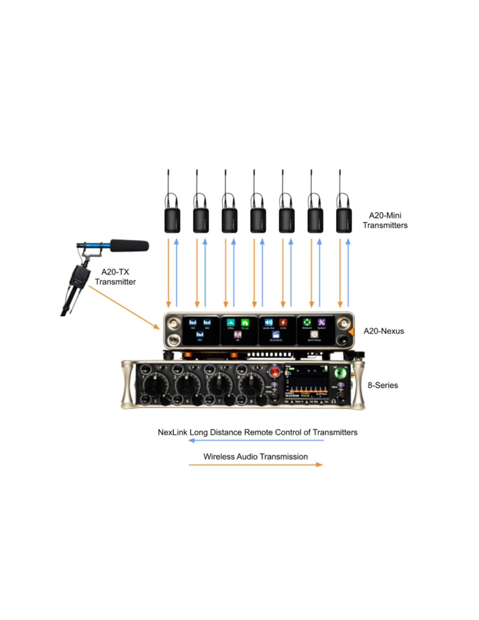
NexLink Wireless Transmitter Control
NexLink is a proprietary 2.4 GHz bidirectional wireless data link technology that allows multiple A20 transmitters to be controlled,
monitored, and timecode synced from an A20-Nexus over long distance. NexLink is designed to offer robust and reliable control
over distances far exceeding that of the wireless audio transmission, even in the presence of Wi-Fi and Bluetooth interference. An
A20-Nexus can pair with up to 64 NexLinked transmitters.
GainForward
The A20-Nexus supports the A20 transmitter’s GainForward feature. GainForward eliminates the need to adjust microphone
preamplifier gain at the wireless transmitter. Audio levels from the transmitter are controlled either directly from the 8-Series (or any
other mixer) trim controls, or from the A20-Nexus receiver screen. If the talent speaks too softly or emotes too loudly after being
A20-Nexus User Guide
4

“wired” with the transmitter, simply adjust the transmitter gain with the mixer’s gain trim, instead of having to access the actual
transmitter. Read more about GainForward at: https://www.sounddevices.com/gainforward-explained/
When an A20-Nexus receiver channel is receiving signal from an A20 transmitter, adjust the receiver channel’s gain, low cut, and
polarity from its associated .1RX view
When the A20-Nexus is docked on an 8-Series, the Nexus’s gain, low cut, and polarity settings are bypassed and hidden. In this
case, adjust the 8-Series’ trim, low cut and polarity gain as necessary. See the 8-Series User Guides for more information.
A20-Nexus User Guide
5

Architectural Overview
The A20-Nexus takes a brand new approach to professional audio receiver design. The A20-Nexus combines several technologies
resulting in a very powerful and versatile product.The diagram below illustrates the architecture of the A20-Nexus.
The first thing to note about the architecture is that there are two entire signal paths. This performs the True Diversity reception
inherent in the design. This is a lavish proposition, as it doubles the circuitry, but it is absolutely the best way to perform spatial
diversity - superior to any type of antenna or phase diversity.
The first section that comes right after the receive antennas is the first SAW filter array. This pre-select filter is a key element of our
unique SpectraBand technology. It allows for a tuning range from 169 MHz - 1525 MHz which is divided into multiple, tightly-filtered
tuning bands. The extremely sharp attenuation at either end of a tuning band’s range significantly reduces unwanted interference
outside the selected tuning band resulting in excellent range performance. Tuning bands vary in width, but tend to be around 24
MHz wide.
Next is the Low-Noise Amplifier (LNA), which is one of the most important stages in the design. This section has been specially
designed for very low noise and high dynamic range, which results in long-range reception and high overload capability. This LNA
stage exhibits a noise figure of only 0.35 dB, one of the very best on the market currently.
This is followed by yet another SAW filter array. This array further attenuates out-of-band signals, ensuring reliable reception, and
greatly suppressing any image frequencies.
The Local Oscillator and Mixer perform the traditional function of a single downconversion superheterodyne radio. This section has
been meticulously designed and is the other key element of our unique SpectraBand technology. This section exhibits extremely low
phase noise and wide dynamic range to accurately downconvert the RF to a lower Intermediate Frequency (IF) for conversion into
the digital domain.
Before conversion into the digital domain, the signal passes through its final array of SAW filters, rejecting any extraneous energy
not wanted in the downconversion, as well as providing anti-aliasing before the Analog-to-Digital (A/D) converter. The A/D converter
is a wideband, extremely high dynamic range part which accurately captures 24 MHz of IF energy into a digital version of that signal.
The real magic of the entire A20-Nexus happens within the Field-Programmable Gate Array (FPGA). An FPGA is essentially a giant
custom, massively-parallel processor programmed in house. The FPGA can perform filtering, frequency conversion, and
demodulation in the digital domain which far exceeds anything that can be done via analog or traditional digital circuitry. The FPGA
can perform demodulation of 16 channels simultaneously. The FPGA also performs the True Diversity operation which not only
selects the best digital word from the two antennas but actually works at the bit level for additional range. The resultant audio signals
are then fed out of the FPGA to the various audio outputs.
A20-Nexus User Guide
6

Panel Views
Front Panel
1 & 3: Antenna Connector A & B
BNC connectors, for connecting to active, passive, or smart antennas.
2: Touch Screens
Color OLED array for control and monitoring.
● Touch can be disabled to prevent inadvertent switching of the screens to different views. Press and hold the Headphone
Knob for > 2 secs to disable. Re-enable by pressing and holding the Headphone Knob for > 2 secs. Disabled touch is
indicated by a thin orange border around the four OLEDs. The Headphone Knob and Triangle button remain active when
touch is disabled.
● Screensaver: To prevent burn in, the OLEDs can be set to turn off after a period of inactivity from the Main
Menu>System>Screensaver setting.
● Lockout Mode: The whole front panel interface (OLEDs, Headphone Knob, and Triangle button) can be disabled to
prevent unauthorized users from accessing settings. See Main Menu>System>Lockout Mode.
4: Triangle Button
● Press to power up. Press and hold to power down.
● When powered up, press to cycle through the current Receiver view, Main Menu, and RTSA. Backs out of sub-menus.
5: Control Knob
● Rotate to adjust headphone output level.
● Rotate to scroll through lists and select parameter values.
● Rotate to scroll frequency cursor or adjust horizontal/vertical zoom in RTSA/Scan view.
● Hold for 3 seconds to enter Show Mode (locks out touch from the screens).
6: Multicolor Ring LED
● Solid blue when powering up
● Red when headphone output is clipping.
● Flashing orange when selected Sync Reference is not detected.
● Solid green when the front panel is locked out. See menu ( ).Main Menu>System>Lockout Mode
7: Headphone Output
3.5 mm connector
A20-Nexus User Guide
7

Rear Panel
1 & 8: Antenna Connector A & B Inputs / Cascade Outs
● BNC connectors for connecting active, passive, or smart antennas.
● Cascade outs for looping through the front panel antenna A & B inputs. Only available when front panel antennas are
selected in the ( ) menu. The cascade out passively splits the incoming signal, resulting in approximatelyMain Menu>RF
3.5 dB of loss. In some situations, additional antenna gain and/or amplification may be desirable to maintain excellent
range.
2 & 14: Top & Bottom D-Sub Audio Output Connectors
25-pin D-Sub connectors for outputting analog (mic/line/guitar level) or AES digital. See menu ( DisabledMain Menu>Audio Output).
when mounted to an 8-Series via the expansion port. Note: the pin-out follows the AES59 standard. The analog output pin-out is
different from the AES digital output pin-out. See section for more information.Connector Pin Assignments
3 & 5: 2.4 GHz Antenna Connectors
Dual SMA-F ports for connecting 2.4 GHz SMA-M antennas for NexLink. Both antennas need to be connected.
Important: Only use the 2.4 GHz SMA-M antennas supplied with the A20-Nexus or equivalent. Do not use 2.4 GHz RP-SMA
antennas such as those used for the 8-Series bluetooth antenna.
4: LTC / Wordclock Input
BNC for connecting LTC or Wordclock input. Nexus auto-detects whether the signal is LTC or Wordclock including the associated
frame rate or sample rate. Disabled when mounted to an 8-Series via the expansion port.
6 & 12: DC Inputs
Dual TA4-M, 10-18V DC inputs. Highest voltage takes precedence. Disabled when docked to an 8-Series via the expansion port.
7 & 11: DC Outputs
Dual, 4-pin Hirose female DC outputs (500 mA max between both outputs) for powering IFB transmitters, camera hops, and other
low power peripherals. Disabled when docked to an 8-Series via the expansion port.
When powered via TA4, voltage is passed through from the DC input (10-18V). When powered via PoE+, DC Outputs supply 12V
DC.
9: USB-A Port
Multi-function USB-A port for:
● Pairing and syncing timecode to A20 transmitters. Connect the transmitter to Nexus using a USB-C to USB-A cable.
● Connecting a USB keyboard for naming channels, quick setup files and network. The USB keyboard is active whenever
the virtual keyboard screen is displayed.
● Mounting a USB thumb drive for updating firmware and loading/saving settings.
Tip: The USB-A port supports USB hubs so that multiple devices can be connected at the same time. Maximum power output of 2.5
Watts (5V, 500 mA)
10: USB-C Port
For factory use only.
A20-Nexus User Guide
8

13: Ethernet Ports 1 & 2
2x RJ45 ports for Dante and/or Control. Nexus can be powered via PoE+ (minimum 25W) via port 1. Dante is disabled when docked
to an 8-Series via the expansion port. Control remains enabled.
15: SFP Port
Accepts a wide variety of Small Form-factor Pluggable (SFP) modular network transceivers, including optical fiber options for
Ethernet Dante and/or Control connection. Dante is disabled when docked to an 8-Series via the expansion port. Control remains
enabled.
16: Factory Access Cover
Covers and protects the factory-use only ports.
Bottom Panel
1: Mounting Point
1 / 4”, 20 screw hole for mounting purposes.
2: Expansion Port
For docking A20-Nexus to an 8-Series mixer/recorder using the A20-QuickDock optional accessory.
The expansion port provides power from the 8-Series and passes the multichannel receiver digital audio signals from A20-Nexus to
the 8-Series. When docked on an 8-Series:
● The A20-Nexus and its NexLinked transmitters are controlled from the Nexus OLED touch screen user interface. The
8-Series interface is not used for control.
A20-Nexus User Guide
9

● A20-Nexus rear panel connectors are disabled apart from the antenna connectors, control network, and the USB-A port.
● The USB-A port has the following capabilities:
○ Pairing A20 transmitters to the A20-Nexus by connecting a USB-C cable from the transmitter to the USB-A port.
○ Attaching a USB keyboard for entering text directly (e.g. receiver channel names) into the A20-Nexus.
○ Mounting a USB thumb drive for updating A20-Nexus firmware and saving setup files.
○ Syncing 8-Series timecode to an A20 transmitter from the A20-Nexus.
3: Screw holes for A20-QuickDock and A20-Shelf
Four screw holes for mounting the A20-Nexus to an A20-Shelf and A20-QuickDock
A20-Nexus User Guide
10
Typical Setups
The versatile A20-Nexus can be used in many types of setup and workflow. This section details just a few examples.
1. Bag Setup: Nexus docked to an 8-Series Mixer-Recorder
The A20-QuickDock accessory enables the A20-Nexus to be docked to an 8-Series mixer-recorder. The bottom panel incorporates
a multi-pin expansion port that connects power from the 8-Series and passes the multichannel receiver digital audio from A20-Nexus
to the 8-Series.
A20-Nexus User Guide
11

2. Remote Setup: Nexus located on set, close to talent
Remotely locating the A20-Nexus multichannel receiver close to talent significantly reduces the chance of RF dropouts since the
distance between those wearing the transmitters and the A20-Nexus receiver is minimized. A single CAT cable can be used to
transport Dante audio and remote control data between Nexus and the sound mixer. As well as sending Dante audio to the mixer,
the Nexus can also receive Dante audio back from the mixer, useful for distributing VoG and/or IFB feeds etc via its analog D-Sub
outputs. In this example, the Nexus Web App is running on a tablet and controlling the Nexus over Wi-Fi.
A20-Nexus User Guide
12

3. Remote Setup: Nexus located on set, close to talent, powered from PoE+
Similar to the previous setup, but with the Nexus being powered over PoE+. In this example, a computer is controlling Nexus via the
Web App and is also sending and receiving Dante to and from Nexus.
A20-Nexus User Guide
13

4. Cart Setup
A typical cart setup with Nexus. As well as sending Dante audio to the mixer, the Nexus can also send audio from its AES or Analog
D-Sub outputs. In this example, the Nexus Web App is running on a tablet and controlling the Nexus over Wi-Fi.
A20-Nexus User Guide
14

Quick Start
This Quick Start guide assumes that the A20-Nexus is being used as a standalone receiver.
1. Connect a 10-18V DC power source to either or both TA4-M DC inputs. Alternatively, connect PoE+ to Ethernet port 1.
2. Connect suitable passive, bias-powered, or smart antennas to either the front or rear BNC A and B antenna ports.
3. If using NexLink to control and monitor A20 transmitters, connect 2.4 GHz antennas to both rear panel 2.4 GHz SMA
ports.
4. Connect required rear panel audio outputs (Analog, AES, and/or Dante) from Nexus to external devices.
5. Connect headphones to the front panel 3.5 mm headphone output.
6. Press the front panel triangle button to power up. Press and hold to power down. When powered up for thePower Up.
very first time, receiver channels 1-8 are displayed. This view is called the 8RX View. All RX channels default to Off.
8RX View
7. Press the triangle button to display the Main Menu.
8. Tap the System icon to enter the System menu.
9. Ensure Country is set to the country that you are in. The Country setting determines which Tuning Bands and RF
frequencies are legally unrestricted and available for selection in the A20-Nexus. If using A20 transmitters, make sure that
the A20-Remote app they are paired to is also set to the same country.
Main Menu
10. Tap the RF icon in screen 2 to access the RF menu.
11. Select Front or Rear antennas by tapping the button at the bottom of screen 2. When ‘Rear’ is displayed, the rear
antennas are selected. When ‘Front’ is displayed, the front antennas are selected.
RF Menu
12. If the antennas require bias-power, tap the A and B antenna gear icons to display A and B antenna settings respectively
and set both their Power (Bias) settings to On.
A20-Nexus User Guide
15

Antenna Settings
The antenna icons will show a lightning bolt icon next to them when bias power is enabled.
13. Pairing is a process that adds A20 transmitters to the A20-Nexus TX List. The TXPair and NexLink A20 transmitters.
List is an inventory of available transmitters that can be selected for wireless remote-control (via NexLink) and assigned to
receiver channels.
Note: A10-TX transmitters cannot be paired or NexLinked with the A20-Nexus.
From the Main Menu, tap the TX List icon.
To pair an A20 transmitter, ensure it has a charged battery or batteries installed, then connect its USB-C port to the
A20-Nexus USB-A port. The A20 transmitter will appear in the TX List after a few seconds. The A20-Nexus will then
automatically establish a NexLink connection between the transmitter and the next available receiver channel. This can
take up to a minute or so. Once connection is established, the NexLink RSSI icon is displayed in the TX List > NexLink
column.
TX List
14. From the TX List, rotate the front panel knob to highlight a receiver channel, then press the knob to jump to its 1RX View
from which the receiver and its NexLinked transmitter can be configured and monitored.
1RX View
A20-Nexus User Guide
16
15. In the 1RX View, ensure the transmitter is within NexLink range by checking that the NexLink RSSI indicator in the
leftmost screen shows good signal strength.
16. If the A20 transmitter is not already on, tap the Power ON button in screen 3 of the 1RX View.
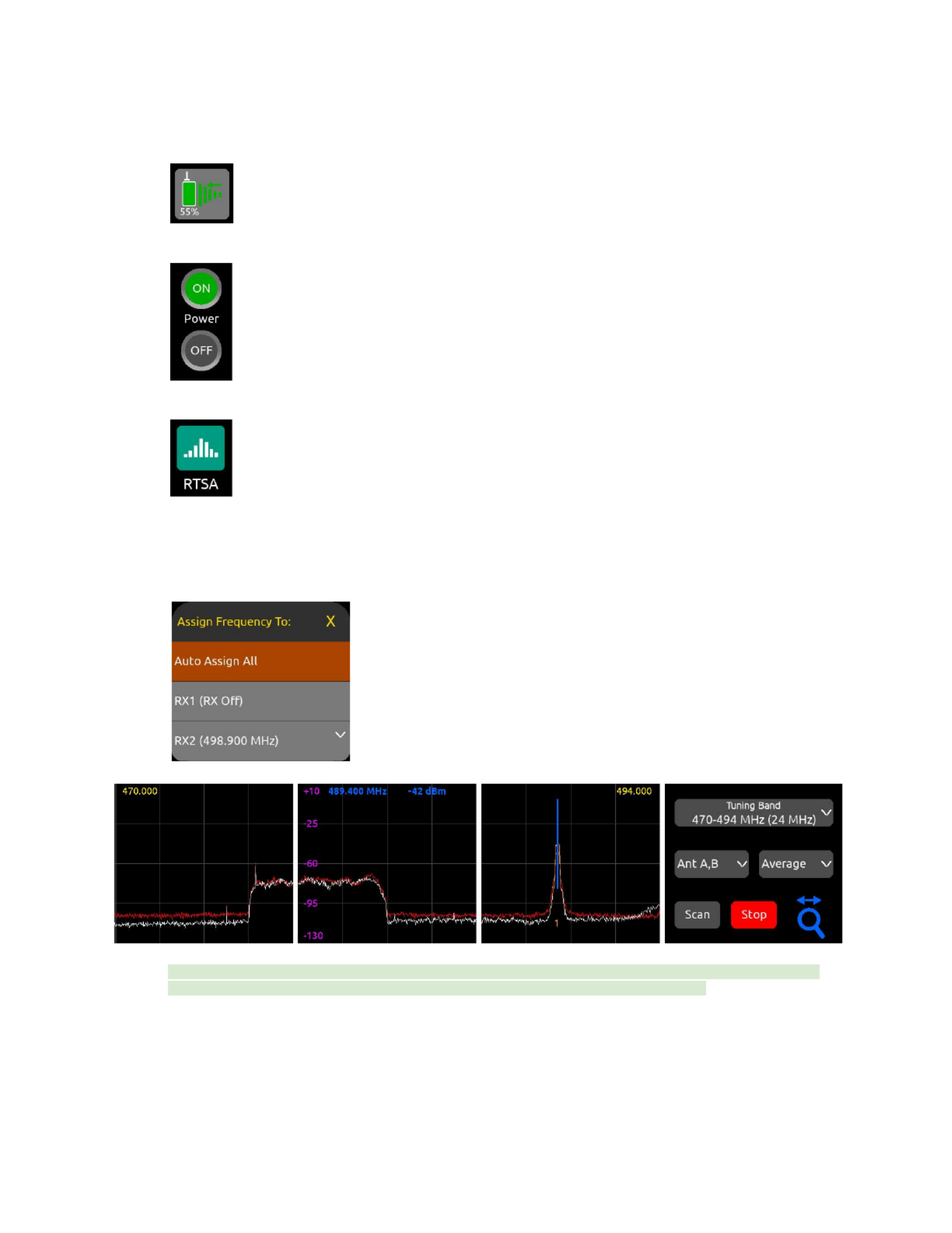
17. Press the triangle button to access the Main Menu, then tap the RTSA icon.
18. In the RTSA, rotate the Control knob (or tap the top half of the plot) to move the blue vertical frequency marker to a clean
frequency (i.e. where there is low background RF noise). Press the Control knob to display the ‘Assign Frequency To:’ list
then tap RX1 to assign the clean frequency to the required receiver channel (in this example, channel 2). The frequency is
automatically pushed to the transmitter and its RF signal appears in the trace. Alternatively, select ‘Auto Assign All’ at the
top of the list to automatically deploy clean frequencies to all active channels.
Tip: Before assigning frequencies, it is highly recommended to perform a scan of the local RF environment using Scan
Mode to identify and choose a clear Tuning Band. See RTSA > Scan Mode for further information.
19. Tap the orange number below the transmitter signal to jump to the 1RX View for that channel number, tap the Gain button
and rotate the Control knob to bring up the gain until you see audio signal from the lav connected to the A20. Press the
Control knob to store the gain value.
20. Put your headphones on and listen. Rotate the Control knob clockwise to increase the HP gain.
Congratulations! You have your first wireless channel ready to go.
A20-Nexus User Guide
17

Powering
The A20-Nexus is powered from TA4 (10-18 VDC), PoE+, from the 8-Series (via expansion port), or via XL-WPTA4
AC mains adapter (purchased separately).
The control knob ring LED illuminates blue during power up, then goes out once fully booted.
When the Nexus is first powered on, the last accessed RX View is displayed.
Tip: Reducing A20-Nexus power consumption:
● Turn off unused receiver channels. See 1RX View.
● Disable Dante by setting Network > Port Configuration to Control Only, All Ports
●Where possible, power via TA-4 or the 8-Series. While PoE is a practical and convenient option for powering the
A20-Nexus remotely, it is slightly less efficient than straight DC. This is due to the finite efficiency of the PoE injector and
the internal PoE supply of the Nexus.
Powering when Nexus is operated standalone (not docked to an 8-Series)
Connect a 10-18 VDC power source (20 watt minimum) to the TA4 DC power inputs and/or PoE+ power source (30 watt minimum)
to ethernet port ‘Dante/Ctrl 1’. Connecting multiple power sources allows for redundancy since the A20-Nexus seamlessly switches
between power sources should one fail. The power source with highest voltage takes precedence and is displayed along with its
voltage beneath the Power menu icon in the Main Menu and in screen 1 of the Power menu.
● To turn Nexus on, press the triangle button or, with Power menu >‘Turn on when power is applied’ enabled, simply
connect a power source.
● To turn Nexus off, press and hold the triangle button until the ‘Powering down ..” progress bar completes.
Powering when Nexus is docked to an 8-Series
Connect power to the 8-Series. Power is supplied to the Nexus from the 8-Series expansion port.
Note: When docked, powering via the A20-Nexus TA4 or PoE+ power inputs is disabled.
Ensure that the 8-Series System Menu > Expansion Port is set to On.
● If Power menu >‘Turn on when power is applied’ is enabled, Nexus automatically powers on when the 8-Series is turned
on.
● If Power menu >‘Turn on when power is applied’ is disabled, turn on the 8-Series then press the triangle button to turn on
Nexus.
● To turn Nexus off but keep the 8-Series on, press and hold the triangle button until the ‘Powering down ..” progress bar
completes.
● To turn off both the 8-Series and Nexus, move the 8-Series power toggle switch to Off.
A20-Nexus User Guide
18

Power Outputs DC Out 1 and DC Out 2
The DC Outs can be used for powering IFB transmitters, camera hops, and other low power peripherals.
Enable or disable each DC Output from the Power menu.
● When powered via its TA4 DC inputs, the A20-Nexus supplies 500 mA maximum between both DC outputs. DC Output
voltage is passed through from the DC input (10-18V).
● When powered via PoE+, Nexus supplies 500 mA maximum and DC Output voltage is 12V DC.
● When powered by the 8-Series, Nexus supplies 3W maximum for each DC Output. Exceeding this limit may cause
malfunction. Voltage dependant on 8-series power source voltage.
A20-Nexus User Guide
19

Navigating the A20-Nexus User Interface
The A20-Nexus is operated from its front panel triangle button, control knob, and four touch screens or remotely via its web
interface.
Triangle Button
● Press to power up. Press and hold to power down.
● When Nexus is powered up, press to cycle between the RX View, Main menu, and RTSA. When in a menu or submenu,
the triangle button exits to the menu above.
Control Knob
● Rotate to adjust headphone output level. The headphone gain is displayed momentarily in the rightmost screen.
● Rotate to scroll through lists and select parameter values. Press to store.
● Rotate to scroll frequency cursor or adjust horizontal/vertical zoom in the RTSA/Scan view.
● Press for 3 seconds to enable Show Mode (screen touch is locked out). Press angina for 3 seconds to disable Show
Mode.
Touch Screen UI Elements
The A20-Nexus uses a number of different UI elements for changing settings i.e. toggle switch, list button, value button, action
button, etc.
Note: When any touch screen UI element is selected, brightness is reduced and touch is disabled on all other touch screens.
● Toggle Switch: Tap to toggle between On and Off. Typically used for functions that have on and off states e.g. Power>DC
Out 1 and DC Out 2.
Off
On
● List Button: Displays a list of items to choose from. A list button is identified by a down arrow inside the button on the
right. The currently selected item is displayed inside the button.
○Tap the list button to display a list of items to choose from.
○Scroll the list of items by rotating the Control or tapping the up/down arrows, then press the Control knob to
select the item and exit the list. Alternatively, tap directly on the list option to select it.
○ To exit the list without making any changes, press the triangle button or tap anywhere in the list’s title bar.
A20-Nexus User Guide
20

● Value Button: Displays a parameter’s value.
○Tap to select - the button turns orange.
○Rotate the Control knob to adjust the value.
○Press the Control knob or tap the button to exit.
● A button that initiates a process e.g. Format USB Drive. The button contains the name of the process.Action Button:
● Two-State Button: A button that has two values or options other than On/Off. The top row labels the function and the
bottom row shows the current setting.
A20-Nexus User Guide
21

3. Indicates the RSSI of the received 2.4 GHz NexLink signal from the transmitter. The RSSI colorNexLink RSSI Meter:
signifies the transmitter NexLink status.
a. Green = Transmitter is on and NexLink active
b. White = Transmitter is off and NexLink active
c. Gray = No connection or out of range
4. Indicates whether the transmitter feeding the receiver channel is recording and/or muted.Record/Mute Status:
a. Red = Recording
b. Blue = Muted
c. Blue fill, red border = Recording and muted
d. Gray = Not recording or muted
5. Displays the receiver channel’s frequency.RF Frequency:
a. If NexLinked to an A20 transmitter and NexLink Tuning Mode is set to Push, it is the same as the transmitter
frequency.
b. Displays ‘RX Off’ when the receiver channel is Off.
c. The frequency flashes red when there is a NexLink issue. Go to the 1RX View > Gear Menu > NexLink Status
screen to determine the cause of the issue.
6. Displays the receiver channel’s RSSI or Q history. See RF Menu.RF History:
7. Indicates the strength of the received wireless audio transmission from the transmitter.A and B RSSI Meters:
8. Indicates the quality of the received wireless audio transmission from the transmitter.Q Meter:
9. Indicates the received audio level from the transmitter. The audio meter scale is -90 to 0 dBFS forAudio Meter:
GainForward sources and -50 to 0 dBFS for non-GainForward sources.
4RX View
● Displays 4 receiver channels, one per screen.
● Tap the right arrow at the bottom of screen four to bank to the next four channels 5-8. In the channels 5-8 bank, tap the left
arrow at the bottom of screen one to bank to the previous four channels 1-4.
● Tap any receiver channel screen to display its 1RX View.
● Tap the RTSA icon at the bottom of screen 4 to display the RTSA in screen 4.
1. Channel Name and Audio Meter: Displays the transmitter (channel) name inside an audio level meter. Tap the meter to
edit the name (12-character maximum) using the virtual keyboard.
a. The transmitter name can be edited if the channel is NexLinked to an A20 transmitter
b. The transmitter name cannot be edited if the channel is being fed from an A10-TX.
A20-Nexus User Guide
23

c. If NexLinked to an A20 transmitter, the name is pushed to the transmitter.
d. The name is rippled to the 8-Series channel that the receiver channel is routed to if docked to an 8-Series and
the 8-Series menu [Channel Setup > Use Wireless Names] is enabled.
2. Displays the receiver channel’s frequency. Tap to edit the frequency.RF Frequency:
a. If NexLinked to an A20 transmitter and NexLink Tuning Mode is set to Push, it is the same as the transmitter
frequency.
b. Displays ‘RX Off’ when the receiver channel is Off.
c. The frequency flashes red when there is a NexLink issue. Go to the 1RX View > Gear Menu > NexLink Status
screen to determine the cause of the issue.
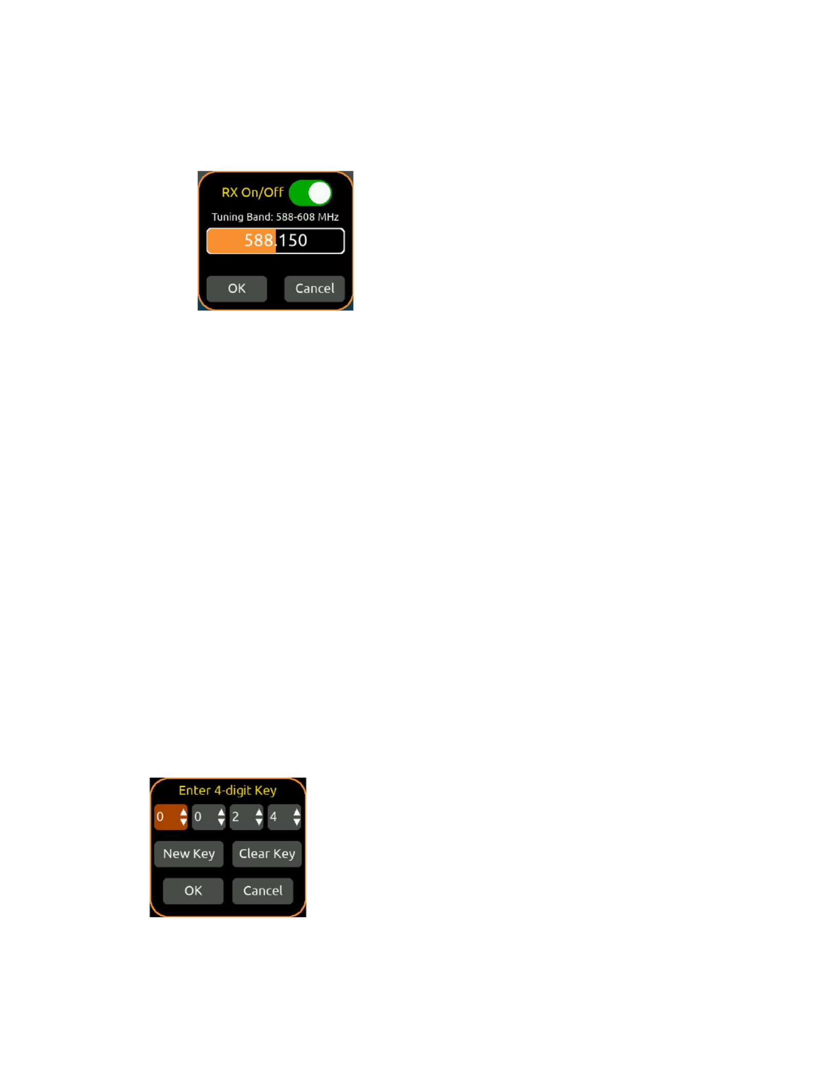
d. Tap the frequency button to select a frequency within the current Tuning Band.
e. To enter a frequency, tap each frequency field then rotate the Control knob to select a value. Tap OK to store or
Cancel to exit without saving. Alternatively, jump through the frequency fields by pressing the Control knob.
f. To save power, turn off a receiver channel by setting the RX On/Off toggle to Off. Alternatively, in the whole
number frequency field (first field), rotate the Control knob fully anticlockwise to display ‘RX Off’.
If NexLinked to an A20 transmitter, the frequency is automatically pushed to the transmitter unless System > More >
NexLink Tuning Mode is set to Manual.
3. HPF: Indicates if the HPF is active either on the transmitter (if an A10-TX) or receiver channel (if an A20 transmitter).
A20-Nexus User Guide
24

1RX View
Displays a receiver channel’s received signal, audio level, control functions and status across the four screens.
Use the 1RX View to perform detailed control and monitoring of a receiver channel and its associated transmitter. The 1RX View has
different control layouts depending on the following criteria:
● The model of the transmitter feeding the channel (A20-TX, A20-Mini, or A10-TX)
● Whether the channel is sourced from one or multiple transmitters.
● Whether the channel is sourced from a NexLinked or non-NexLInked (e.g. A10-TX) transmitter.
● Whether the channel’s Mode is set to RF Only, REC Only, or RF+REC
● Whether the A20-Nexus is standalone or docked to an 8-Series mixer/recorder
Some 1RX View Layout examples
A20-Nexus
Mode
Description
1RX View Layout
Standalone
REC+RF
Channel sourced from a
single A20 transmitter
(See Example 1 below
for a detailed description)
Standalone
RF Only
Channel sourced from a
single A20 transmitter
Standalone
REC+RF
Channel sourced from
multiple A20 transmitters
(See Example 2 below
for a detailed description)
Docked
RF Only
Channel sourced from a
single A20 transmitter
(expansion license
installed)
Standalone
--
Channel sourced from an
A10-TX or non-NexLink’d
transmitter
Standalone
--
No transmitters are
assigned to the channel.
Tap the TX List button to
assign a transmitter.
A20-Nexus User Guide
25

Example 1: 1RX View when sourced from a single A20-TX transmitter in REC+RF Mode, Standalone
● Navigate to the next or previous channel’s 1RX View by tapping the right and left arrows at the bottom of screen 4.
● Navigate to other RX Views by tapping the RX View icons at the bottom of screen 3.
● Tap the RTSA icon at the bottom of screen 4 to display the RTSA for the selected channel frequency in screen 4. The
RTSA is approx 1 MHz wide and centered on the selected frequency. Tap the RTSA to jump to the full RTSA for the
currently selected Tuning Band.
1. Channel Name and Audio Meter: Displays the transmitter (channel) name inside an audio level meter. Tap the meter to
edit the name (12-character maximum) using the virtual keyboard. The audio meter scale is -90 to 0 dBFS for
GainForward sources and -50 to 0 dBFS for non-GainForward sources, i.e. A10-TX.
a. The transmitter name can be edited if the channel is NexLinked to an A20 transmitter
b. The transmitter name cannot be edited if the channel is being fed from an A10-TX.
c. If NexLinked to an A20 transmitter, the name edits are pushed to the transmitter.
d. The name is rippled to the 8-Series channel that the receiver channel is routed to if docked to an 8-Series and
the 8-Series menu [Channel Setup > Use Wireless Names] is enabled.
2. Transmitter Battery Level Icon: Indicates the remaining transmitter battery charge as a color and in % or V depending
on the type of battery the transmitter is using. If an AA or AAA, the battery level is displayed as a voltage. If an NP-BX1,
then it is displayed as a %.
a. Gray = Transmitter is Off
b. Green = Good
c. Orange = OK
d. Red = Low
e. Flashing Red = Depleted (transmitter RF and audio is disabled)
3. Indicates the RSSI of the received 2.4 GHz NexLink signal from the transmitter. The RSSI colorNexLink RSSI Meter:
signifies the transmitter NexLink status.
a. Green = Transmitter is on and NexLink active
b. White = Transmitter is off and NexLink active
c. Gray = No connection or out of range
For receiver channels that are sourced from a single transmitter, tap the NexLink RSSI meter to display the NexLinked
Transmitter List from which you can select an A20 transmitter to NexLink to.
A20-Nexus User Guide
26
4. RF Frequency: Displays the receiver channel’s frequency.
a. The frequency flashes red when there is a NexLink issue. Go to the 1RX View > Gear Menu > NexLink Status
screen to determine the cause of the issue.
b. Tap the frequency button to select a frequency within the current Tuning Band.
c. To enter a frequency, tap each frequency field then rotate the Control knob to select a value. Tap OK to store or
Cancel to exit without saving. Alternatively, jump through the frequency fields by pressing the Control knob.
d. To save power, turn off a receiver channel by setting the RX On/Off toggle to Off. Alternatively, in the whole
number frequency field (first field), rotate the Control knob fully anticlockwise to display ‘RX Off’.
If NexLinked to an A20 transmitter, the frequency is automatically pushed to the transmitter unless System > More >
NexLink Tuning Mode is set to Manual.
5. RF History: Displays the receiver channel’s RSSI or Q history. See Menu > RF.
6. A and B RSSI Meters: Indicates the strength of the received diversity signal from the transmitter.
7. Q Meter: Indicates the quality of the received diversity signal from the transmitter.
8. Gain: Adjusts receiver channel gain, -6 to 60 dB. Unavailable when docked to an 8-Series; use 8-Series channel trim
gains instead.
9. HPF: Adjusts receiver channel HPF (Off, 40, 60, 80, 100, 120, 160, 200 Hz). Unavailable when docked to an 8-Series;
use 8-Series channel HPF instead.
10. More: Tap to access a second page of settings including:
a. Adjusts the polarity of the channel audio between Normal and Reverse. Unavailable when docked toPolarity:
an 8-Series; use 8-Series channel polarity instead.
b. This setting is only available in a transmitter’s TX View and when the transmitter is assigned toAudio Offset:
an RX channel with more than one transmitter assigned. The audio offset is a value stored in the A20
transmitter that tells the receiver channel it is feeding to apply a gain offset to the incoming transmitter audio
signal. When a receiver channel has multiple transmitters assigned, this can be used to compensate for the
different transmitter audio output levels resulting from microphones/lavs with different sensitivities.
c. Sets a NexLinked A20 transmitter’s Mode. Options are RF only, REC only, and REC+RF (non-US TXMode:
models only or A20-TX models not set to Lav).
d. Tap to access the first page of settings.More:
11. Privacy: Tap to set a Privacy Key. This prevents unauthorized A20 receiver users deciphering the transmitter audio
signal. Tap New Key to generate a random 4-digit key or Clear Key, to reset to zeros. The key is pushed to NexLinked
transmitters assigned to the receiver channel.
12. Modulation: Sets Modulation between Standard and Long Range. Compared to Standard Modulation, Long Range
Modulation has better sensitivity. This increased sensitivity results in better range in challenging RF environments. The
Modulation setting must match between the transmitter and the Nexus in order for the transmitted signal to be received.
A20-Nexus User Guide
27

If NexLinked to an A20 transmitter, the modulation setting is automatically pushed to the transmitter unless System >
More > NexLink Tuning Mode is set to Manual.
13. RF Power: Sets a NexLinked A20 transmitter’s RF power. Options are RF Off, 2 mW, 10 mW, 20 mW, 40 mW.
14. Power On/Off Buttons: Tap to power on and off the transmitter and receiver channel.
15. Record Start/Stop Buttons and Status: Tap to start and stop the transmitter recording. Record button is red when
recording. The record stop/start buttons are not displayed when the A20 transmitters are in RF Only mode.
16. Mute On/Off buttons: Tap to mute and unmute the transmitter.
17. ID On/Off Buttons: Tap to identify the A20 transmitter. Its LEDs will start flashing.
18. LEDs On/Off buttons: Tap to enable or disable the A20 transmitter’s LEDs.
19. Transmitter Timecode Status (only available in Rec Only or Rec+RF mode): Tap the TC Icon to display whether the
A20 transmitter has synced successfully to the A20-Nexus. Displays ‘TC synced’ when successfully synced. Tap again to
return to the TC Icon.
Note: A20 transmitters hold their synced timecode accurately for 4 hours after power down, then reset.
20. Gear Menu: Provides access to two pages of other transmitter settings plus NexLink Status alerts. Available options
depend on A20 transmitter model, A20-Mini or A20-TX.
Gear Menu Page1/2
a. Displays various status alerts relating to communication over NexLink. SeeNexLink Status: NexLink Status
Alerts
b. Set to ON to have the A20 transmitter automatically power on whenAuto-Power A20 with Lemo Connection:
a lav mic is connected.
c. Set to ON to have the A20 transmitter automatically resume recordingResume Record upon Powering On:
on power up if it was recording prior to powering down.
d. Allows the selection of 40 mW for RF Power. Rarely required.A20 Allow Extra HIgh RF Power:
e. Sends a command to the A20 transmitter to format its recording media. Select OK or Cancel at theFormat TX:
‘Are you sure you want to format?’ prompt.
f. Sends a command to the A20 transmitter to restore its setting to factory defaults.Restore TX Settings:
g. Selects Page 2/2. Available options depend on A20 transmitter model, A20-Mini or A20-TX.More …
Page 2/2 for A20-Mini
h. A20-Mini Only. Set to ON to have an A20-Mini transmitterPower A20 when Removed from PowerStation:
automatically power on when removed from a PowerStation-8M. Not available for the A20-TX transmitter.
i. A20-Mini Only. When set to YES, the battery remaining % indicator adapts toA20 Battery Doubler Installed:
the A20-BatteryDoubler’s discharge characteristics in order to provide accurate readings.
j. Transmitter Information: Displays the NexLinked transmitter’s model, firmware version and serial number.
A20-Nexus User Guide
28

Page 2/2 for A20-TX
k. XLR Input Type: A20-TX Only. Select Mic, Line, P12, P48, AES3-1, AES3-2, AES42-1, or AES42-2. If Lav or
Guitar are connected to the A20-TX, they are automatically selected. When a Guitar is detected, the Guitar
Cable Capacitance and Input Impedance options below are un-grayed.
l. A20-TX Only. Selects chemistry type: NiMH, Alkaline, Lithium Primary or Li-ion, LiFE.Battery Chemistry:
m. A20-TX Only. Select from On, Front Only, or Top OnlyLED Mode:
n. A20-TX Only. Selects the function of the optional toggle switch. Select from None, PowerA20-TX Switch:
On/Off, Mute On/Off, Record/Stop, and RF On/Off.
o. A20-TX Only. Selects Light or Dark background colorDisplay Background:
p. A20-TX Only. Select between Normal or Flipped.Display Orientation:
Example 2: 1RX View when sourced from multiple A20 transmitters in REC+RF Mode, Standalone
Many of the controls are the same as those described in Example 1. However, this 1RX View displays only those functions which
are common to the receiver channel and all assigned transmitters. To change settings pertaining to only one of the assigned
transmitters, tap 'Configure Transmitters…’ , highlight the transmitter, then tap TX View. The TX View can also be accessed from the
TX List.
When a receiver channel is sourced from multiple transmitters, the Assigned Transmitters list in OLED 3 displays a list of all
assigned transmitters. The transmitter name shown in OLED 1 and the one shown in green font in the Assigned Transmitters list, is
the transmitter that is currently being received by the channel over the forward link.
Frequency, Modulation, and Privacy settings are applied to all assigned transmitters when NexLink Tuning Mode is set to Push.
Note: Make sure to have only one assigned transmitter powered up at a time otherwise they will interfere with one another. Power
On/Off buttons are conveniently included in the view accessed by tapping ‘Configure Transmitters…’, to make it easy to ensure
only one transmitter is powered on at a time: select a transmitter in the list then tap the power ON or OFF buttons as necessary.
A20-Nexus User Guide
29

Menus
All the A20-Nexus settings are organized into menus which are accessed via the top level Main Menu.
The triangle button cycles between the current RX view, Main Menu, and RTSA. Press the triangle button one or two times to
display the Main Menu. The leftmost touch screen displays icons for the various RX views. Tap an RX View icon to jump to its RX
View.
Main Menu
Menu
Description
1RX
Displays a receiver channel’s received signal, audio level, control functions and status across the four screens.
See Operating the A20-Nexus
4RX
Displays 4 receiver channels, one per screen. See Operating the A20-Nexus
8RX
Displays 8 receiver channel strips, two per screen. See Operating the A20-Nexus
ALL
Only available if expansion licenses are installed. Displays 12 or 16 channel strips depending on how many 4-ch
expansion licenses are installed.
RTSA
Displays the Real Time Spectrum Analyzer, a real time spectrum analysis tool for assisting in frequency
coordination and selection of clean tuning bands and RF frequencies.
TX List
Displays an inventory of paired transmitters and to which RX channels they are NexLinked. Pair/Unpair and
view a transmitter’s settings. Power On/Off all NexLinked transmitters with one button press.
AutoAssign
Tap to automatically scan the current tuning band for clean frequencies and assign them to active channels. The
clean frequencies are automatically pushed to NexLinked transmitters.
RF
Accesses antenna, tuning band, and RF History settings.
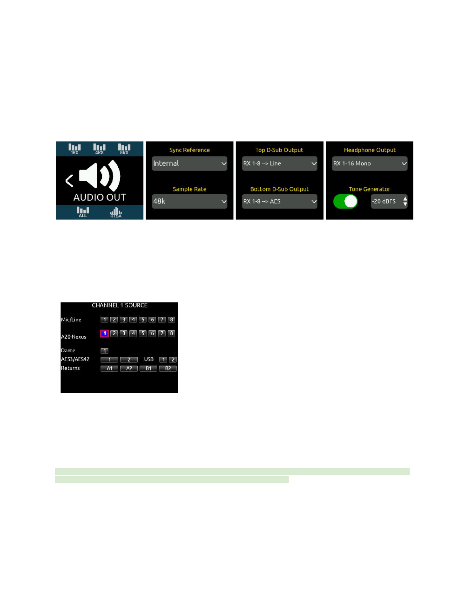
Audio Out
Accesses D-Sub outputs, headphone output, sync reference, sample rate settings, and tone generator settings.
Power
Displays the DC input voltage. Enables/disables DC Out 1 and 2 and configures whether the A20-Nexus should
power on automatically when power is applied.
TX Group
Accesses the Transmitter Group Control menu where commands can be sent to all transmitters simultaneously.
Commands include Power on/off, Record on/off, Mute on/off, LEDs on/off, RF Power, Modulation, Mode,
Format, and ID.
Timecode
Displays incoming LTC BNC timecode and frame rate
Network
Network-related settings for Dante and Control
A20-Nexus User Guide
30

System
2 pages of various system settings:
Page 1 includes screen, country, date/time, format USB drive, and firmware update functions.
Page 2 includes operations pertaining to NexLink, Global TX Settings, installing plugins, Web App Password
and more.
Quick Setup
Load and Save Setup files for quick recall. Setups can be saved to 4 internal memory slots or to an external
USB drive connected to the USB-A port.
Tip: When in a menu, there are two ways to back out to the menu above.
1. Press the triangle button.
2. Tap the leftmost screen (except when in the RTSA menu).
A20-Nexus User Guide
31

RTSA (Real Time Spectrum Analyzer)
The RTSA is a real time, visual spectrum analysis tool for assisting in frequency coordination and selection of clean RF frequencies.
The RTSA can operate over the entire SpectraBand range (169 MHz to 1525 MHz). The RTSA trace represents RF signal level (in
dBm) on the vertical axis and RF frequency on the horizontal axis.
It has two modes of operation:
● Real time analysis of the currently selected Tuning Band while maintaining reception of multichannel wirelessRTSA:
audio.
● Real time analysis of the entire or user-selectable portions of the 470-1525 MHz spectrum. All channel audio isScan:
muted while scanning.
Typical Workflow
It is recommended to first use Scan mode to find the cleanest Tuning Band, then use RTSA mode to find the cleanest frequencies
within that Tuning Band. Once clean frequencies are found they can be assigned to receiver channels and their associated
NexLinked transmitters directly from the RTSA View.
The RTSA View can be displayed on a single screen (touch screen 4) or expanded across all 4 touch screens.
Single Screen RTSA View
● From any RX View, show the single screen RTSA View on screen 4 by tapping the RTSA icon at the bottom of screen 4.
● Hide the single screen RTSA view by tapping the ‘X’ at the top right of the view.
● Change the vertical ‘dBm’ scale by tapping the up/down arrows.
● Switch to the expanded RTSA view by tapping the center of the screen.
● The single screen RTSA view is also displayed in the RF menu.
Expanded RTSA View
● Access the expanded RTSA View by tapping the center of the single screen RTSA View or by tapping the RTSA icon in
the Main Menu or bottom of screen 1 in other menus.
● Exit the expanded RTSA View by pressing the triangle button.
A20-Nexus User Guide
32

1. Shows the minimum frequency of the display.Minimum Frequency:
2. Tap anywhere in the top half of the three OLEDs to locate the blue frequency marker at any desiredFrequency Marker:
frequency. To more precisely position the marker, rotate the Control knob with the Zoom Tool set to horizontal scroll mode
(blue Zoom Tool icon). The marker can be used to identify a specific frequency and its received signal strength.
Press the Control knob to display the “Assign Frequency To:” list. Assign the blue frequency marker’s current frequency to
any receiver channel or select ‘Auto Assign All’ to automatically scan and assign multiple clean frequencies at once. See
AutoAssign for more information.
3. Displays the Frequency Marker’s current frequency and dBm value.Marker MHz/dBm:
4. Shows the maximum frequency of the display.Maximum Frequency:
5. Selects which antenna (Ant) signals are displayed.Antenna Options:
a. Ant A: Only antenna A (red line)
b. Ant B: Only antenna B (white line)
c. Ant A+B: Highest of Ant A and Ant B.
d. Ant A,B: Both Ant A and Ant B.
6. Tuning Band: Sets the A20-Nexus’s Tuning Band and displays its trace across the first three screens. The Tuning Band
can also be set from the RF Menu.
A Tuning Band is a tightly-filtered frequency band from within which Nexus’s receiver channels must operate. RF signals
outside the selected tuning band are sharply attenuated to significantly reduce unwanted out-of-band RF interference. See
Architectural Overview for further information
● Tap the Tuning Band button. If System > More > ‘Show Audio Off Warnings’ is enabled, a popup appears to
warn that audio will stop on all channels if the Tuning Band is changed. Select OK to display a list of the
currently selected Country’s Tuning Bands and their width in MHz. Country is set from the System menu.
Tuning Band List
A20-Nexus User Guide
33

● With the Tuning Band list open, rotate the Control knob to scroll through the list. To make it easy to select a
Tuning Band with the least amount of RF congestion, the Tuning Band and its RTSA display switches ‘live’ as
the list is scrolled.
● Tap the Tuning Band list title bar to close the Tuning Band list.
Quick Recall of a Tuning Band’s Assigned Frequencies
Each Tuning Band’s assigned receiver channel frequencies are stored and automatically recalled when selecting a Tuning
Band. This is particularly useful for:
a) Quickly comparing the RF performance of assigned frequency groups as you switch between tuning bands.
b) Pre-configuring alternate tuning bands with pre-assigned frequencies to prepare for unforeseen changes in the
RF environment.
Note: Each Tuning Band’s assigned frequency cache is cleared when Nexus is powered down.
7. Trace Type: Sets the trace characteristic. Choose from Normal, Average, or Peak Hold.
8. Tap the Zoom icon to cycle the Control knob’s rotate function between the three zoom modes - marker locateZoom Icon:
(blue), zoom horizontal (yellow), and zoom vertical (pink). Tapping to locate the frequency marker automatically changes
the Zoom icon to the blue marker locate function.
9. Tap to start or stop the RTSA or Scan mode. Pressing stop freezes the current display.Stop/Start Button:
Tip: Use the Nexus Web App to export RTSA data as a .csv and .png file.
10. Tap to switch between RTSA and Scan modes. When switching to Scan mode, the following popupScan/RTSA Button:
is displayed if System > More > ‘Show Audio Off Warnings’ is enabled.
“Changing to Scan Mode will stop audio on ALL channels. Continue? [OK, Cancel]”
11. Indicates the frequency and channel number of a NexLinked receiver channel. The channelNexLink Channel Indicator:
number and frequency portion of the trace that is associated with that number, is highlighted orange. Tap the orange
number to jump directly to that channel’s 1RX View.
12. Vertical dBm scale: Displays the vertical dBm scale. Adjust the scale using the Pink Zoom Tool. Choose from +10 to
-130dBm, -10 to -130 dBm, -30 to -130 dBm, and -50 to -130 dBm
13. Trace: The real time trace of the received RF spectrum.
14. Vertical gray region indicates unselectable restricted frequencies.Restricted Frequency Band:
RTSA showing restricted frequency band
A20-Nexus User Guide
34

Scan Mode
Use Scan mode to view the whole Nexus 169 MHz - 1525 MHz spectrum and zoom in to see smaller sections in more detail.
The complete scan trace is refreshed a few times a second. Scan mode makes it quick and easy to find and select a clean Tuning
Band.
● The scan plot width is adjusted using the zoom horizontal (yellow zoom icon) tool. Scroll Control knob clockwise to zoom
in and counter-clockwise to zoom out.
● Tapping the '>' banks to the next range of frequencies with the same width. For example, if 470 to 616 MHz is currently
displayed, tapping ‘>’ will display 616 to 762 MHz.
● Tapping the '<' banks to the previous range of frequencies with the same width.
● When entering Scan mode, the last selected range is shown.
● The scan plot shows tuning bands as colored regions at the bottom of the display. Many tuning bands have overlapping
frequencies. These overlapping frequencies are shown as gray regions.
● To select a Tuning Band:
○ Locate the vertical blue frequency marker within a Tuning Band, then press the Control knob to select the
Tuning Band that the marker is located in.
○ If the blue frequency marker is located within an overlapping Tuning Band ’gray’ region, pressing the Control
knob will display a prompt asking to select the Upper or Lower Band. Cancel the popup by pressing the triangle
button.
● When a Tuning Band is selected, the RTSA mode is automatically selected for that Tuning Band.
AutoAssign
Tap the Main Menu > AutoAssign icon to analyze the whole or part of the current tuning band for multiple clean frequencies and
automatically assign them to active* channels. If System > NexLink Tuning Mode is set to ‘Push to transmitter’, those frequencies
are automatically assigned to NexLinked transmitters. *An active channel is 1) a NexLinked channel or 2) a non-NexLinked channel
that has a frequency assigned.
1. Tap the AutoAssign icon. The RTSA View appears with the full tuning band range highlighted blue. The AutoAssign Range
popup is displayed in screen 4 with the Start button already selected.
A20-Nexus User Guide
35

TX List
The A20-Nexus TX List is an inventory of all paired A20 transmitters and which RX channels, if any, they are assigned to. Up to 64
transmitters can be paired with the A20-Nexus. ‘Pairing’ is a process that establishes a NexLink wireless connection between the
A20-Nexus and A20 transmitter. Once paired, an A20 transmitter can be controlled and monitored from its TX View and, if assigned
to a receiver channel, from its associated 1RX View.
One or more A20 transmitters can be assigned to a receiver channel. When the A20-Nexus is set to ‘Push’ mode (see
System>NexLink Tuning Mode), all transmitters assigned to a receiver channel are sent that channel’s RX Frequency, Modulation,
and Privacy settings. This makes it easy to quickly switch between transmitters assigned to the same receiver channel, particularly
useful in live scenarios such as switching to a backup transmitter or switching between a performer’s different mics or instruments
that are being fed to the same channel on an external mixer.
NOTE: When multiple transmitters are assigned to the same receiver channel, ensure that only one of those transmitters is powered
on, otherwise signals from these multiple transmitters will interfere with each other since they will all be operating on the same
frequency.
Pairing an A20 Transmitter to the A20-Nexus
To establish NexLink wireless control between an A20 transmitter and the A20-Nexus, the transmitter must be added to the TX List
in a process called ‘pairing’. Once paired, a transmitter can be assigned to a receiver channel. Paired transmitters that are not
assigned to a receiver channel can still be controlled over NexLink via the TX View.
1. Enter the TX List by tapping the TX List icon in the Main Menu.
2. Connect the A20 transmitter’s USB-C port directly to the A20-Nexus USB-A port or via a USB hub. It is not necessary for
the A20 transmitter to be powered on or for it to have a battery installed.
3. Wait for several seconds while the A20 transmitter pairs to the Nexus. The A20 transmitter will appear at the top of the list
once paired.
4. Disconnect the USB cable connecting the A20 transmitter to the Nexus.
Pairing automatically assigns the transmitter to the next available receiver channel number. Should that transmitter not be required
for a particular production or job, simply un-assign it by setting its channel number to ‘-’.
Once transmitters are paired, they remain permanently in the TX List until unpaired.
Tip: Use a USB Hub (or PowerStation-8M) to pair multiple A20 transmitters simultaneously by connecting it to the
A20-Nexus’s USB-A port.
Unpairing Transmitters from the A20-Nexus
Rotate the Control knob to select a transmitter in the list, then tap the Unpair button in OLED 4. An ‘Are you sure …” popup appears.
Tap OK to unpair and remove the transmitter from the TX List.
TX List Description
The TX List displays the following columns:
● Name: The name of the paired transmitter. Tap to edit the name.
● Chan: The receiver channel number to which the transmitter is assigned. Tap to assign. Unassign by setting to ‘-’.
● Power: Displays the transmitter’s power status and battery level. A battery icon with gray fill is powered off.
● NexLink: Displays NexLink status.
○ ---: Waiting to hear from the A20 transmitter
○ Connecting: Establishing NexLink communication.
A20-Nexus User Guide
37

○ Initializing: Initializing connection.
○ NexLink RSSI icon: NexLink communication established. Displays the quality of the NexLink signal.
■ When TX is on, the RSSI level display is green
■ When TX is off but NexLink is active, the RSSI level display is white
■ When TX has no Nexlink communication, the RSSI level display is gray.
● Freq: Displays the transmitter’s frequency.
The TX List is sorted according to ascending receiver channel (Chan) number. When multiple transmitters are assigned to the same
receiver channel, they are sorted in alphabetical order within that channel number’s group.
Assigning a Paired Transmitter to a Receiver Channel
Assigning a paired transmitter to a receiver channel enables synchronization of frequency, modulation, and privacy settings between
the transmitter and that receiver channel. Up to 16 transmitters can be assigned to the same receiver channel.
1. Rotate the Control knob to select a transmitter, then tap the ‘Chan’ box.
2. Rotate the Control knob to choose a channel number, then press the Control knob to store.
a. If the selected receiver channel has no transmitters already assigned, the selected transmitter is immediately
assigned to that channel.
b. If the selected receiver channel already has one or more transmitters assigned to it, a popup is displayed in
OLED 3 prompting whether the selected transmitter should be assigned to that receiver channel too. Click OK
to assign.
c. If you are only working with a single transmitter per receiver channel, you can select that single transmitter
directly from that channel’s 1RX View. In the 1RX View, tap the NexLink Icon to display the ‘NexLinked
Transmitter’ List from which you can select an A20 transmitter.
Tip: Rotate the Control knob to scroll through the TX List. Select a transmitter by highlighting its row, then press the
Control knob to jump directly to its receiver channel’s 1RX View.
Tip: The TX List icon in the Main Menu is yellow if not all transmitters are connected and green when all transmitters are
successfully connected or when no transmitters have been paired. If using the A20-Remote app for control, it is best
practice to fully close the A20-Remote app or disable transmitter control in the app’s Manage Transmitters view until
transmitters are shown as connected in the TX List.
TX View
Tap the TX View button to access the selected transmitter’s settings. The button is grayed out when the transmitter is not connected
via NexLink. TX settings can also be accessed via the 1RX View of the receiver channel that the transmitter is assigned to.
For a detailed description of many of the TX View’s controls which it shares in common with the 1RX View and its Gear menu, see
1RX View.
Power All Transmitters On/Off Buttons
Tap On to power on all NexLinked transmitters. Tap Off to power off all NexLinked transmitters. Other transmitter group commands
are available in the TX Group menu. See TX Group.
Note: If multiple transmitters are assigned to a receiver channel, only the last transmitter being received over the forward link is
powered on.
A20-Nexus User Guide
38

RF Menu
The RF Menu accesses antenna, tuning band, and RF History settings.
From the Main Menu, tap the RF icon to enter the RF Menu.
Antenna A/B Setup
The antenna inputs A and B can be switched as a pair between the front or rear panel BNCs. When set to front, the antenna’s
matching rear BNC can be set to Cascade Out, ideal for daisy chaining units.
When daisy chaining A20-Nexus, it is recommended to use an external powered antenna to overcome the 3 dB splitting loss in the
Nexus so that the receivers maintain excellent range.
● Tap to toggle between the Front and Rear BNCs for the A and B antenna inputs.Antenna In button:
● Tap to access settings for the A and B antennas.A,B Gear Icons:
○ Provides 12 VDC bias power for active or smart antennas.Power (Bias): When On, a lightning power icon
appears next to the antenna’s icon in the RF Menu. When setting Power (Bias) to On, a “Turn on Antenna Bias
Power” prompt is displayed. Select OK to turn on bias power.
○ When the Front/Rear antenna input button is set to Front, the rear BNCs can be set as cascadeCascade out:
outs for daisy chaining units. The Cascade out option is grayed out when the antenna BNC inputs are set to
Rear.
○ Tap to enable remote control of the Wisycom LFA smart antenna. The LFA control settings areSmart Antenna:
grayed out when Smart Antenna is disabled. After turning power bias On, allow about 20 seconds for the smart
antenna fields to become accessible.
○LFA Gain Mode: Sets gain of Antenna A or B in 1 dB steps. [Off, Bypass, -12 to 27dB].
○LFA Gain: Sets gain of Antenna A or B in 1 dB steps. [Off, Bypass, -12 to 27dB].
○LFA Filter Type: Sets the filter type of Antenna A or B. [WB (Selected in Freq field: 410-810, 410-700, 410-600,
470-810, 470-700, 470-600, 510-810, 510-700, 510-600); NB (940-960MHz, freq is fixed at 940-960 and cannot
be changed).
○LFA Filter Freq: Sets the filter freq of Antenna A or B. [When Filter is set to NB, Frequency is fixed at 940-960
and cannot be changed. When Filter is set to WB, Freq can be set to 410-810, 410- 700, 410-600, 470-810,
470-700, 470-600, 510-810, 510-700, 510- 600. When Filter is set to Tunable, Filter Frequency can be adjusted
in 40 MHz blocks from 410-450 to 690-730 in 1 MHz steps.]
○LFA Name: Displays name of Antenna A/B.
○LFA Display Brightness: Sets Antenna A/B display brightness in increments of 1. [1-10]
○LFA Display Color: Sets Antenna A/B display color. [White, Black]
○LFA Display Timeout: Sets the duration of Antenna A/B display timeout in steps of 1 second. [5 to 240
seconds]
○LFA Display Rotate: Sets the rotation of the Antenna A/B display. [0 or 180]
○LFA LED: Sets Antenna A/B LED activity. [On or Off]
○LFA Version Info: Displays system information about the Wisycom LFA- B-F1.
● Tuning Band: Sets the A20-Nexus’s Tuning Band and displays its trace across the rightmost screen. The Tuning Band
can also be set from the RTSA. See RTSA and Architectural Overview for more information.
● RF History: The RF History plot is displayed in the 1RX, 4RX, and 8RX Views. It displays RF signal level (RSSI) or link
quality history over a specified duration.
A20-Nexus User Guide
39

● Set from 30 to 600 seconds in 10 second steps.Duration:
●Type: Choose from the following:
○ RSSI: Displays Antenna A or B’s RSSI, whichever is the highest. Displayed a green bars.
○ Link Q: Displays Link Quality. Displayed as purple bars.
○ RSSI + Q: Displays RSSI, Link Quality, and RF overload status.
■ Purple bars for Link Q
■ Blue line for Ant A RSSI and
■ White line for Ant B RSSI.
■ Orange bars indicate that the antenna inputs are approaching overload and
■ Red bars indicate that the antenna inputs are overloading.
See Antenna RF Overload Indication below.
Antenna RF Overload Indication
The A20-Nexus indicates whether its A and B antenna inputs are approaching overload or overloading.
● Red = Overload
● Orange = Approaching overload
● Left indicator (in OLED 1) = A antenna overload status
● Right indicator (in OLED 4) = B antenna overload status
● The red and orange indicators are held for a minimum of 2 seconds. Tap the indicator to manually clear it for at least 10
seconds.
Tip: Things to try when an RF signal is approaching overload or overloading an antenna input:
● Increase the distance between transmitter and receiver antennas
● Reduce RF power on the transmitter
● If using amplified external antennas, reduce the amplifier gain
● Use the RTSA screen to examine from where the interference is coming. If the interference is not from the transmitters in
use but rather some other sources, consider changing the tuning band and frequency such that the interfering RF signal is
moved out of band.
A20-Nexus User Guide
40
Audio Outputs
When standalone, the A20-Nexus delivers its multichannel receiver audio via analog, AES, and Dante outputs. It can also be set up
to convert incoming Dante audio and output it as analog or AES.
When docked to an 8-Series mixer/recorder, the Nexus’s multichannel receiver audio is output via the expansion port to the 8-Series
and Nexus’s analog, AES, and Dante outputs are disabled.
Audio Outputs are configured in the Audio Out Menu.
Routing A20-Nexus Receiver Audio when Docked to an 8-Series Mixer/Recorder
From an 8-Series channel screen, select any one of the A20-Nexus’s receiver outputs as channel source. A20-Nexus receiver
outputs are only shown when an A20-Nexus is docked via the expansion port and enabled via the 8-Series System > Expansion
Port menu.
888 Mixer/Recorder Channel Screen
Routing A20-Nexus Receiver Audio to Dante Outputs
The A20-Nexus receiver’s outputs [1-8] are hardwired to its Dante transmit channels [1-8] respectively.
Nexus’s Dante transmit channels are named A20Nexus_Tx1, A20Nexus_Tx2, A20Nexus_Tx3 etc.
Use Dante Controller running on a MAC or PC computer to route Nexus’s Dante outputs to any Dante device on the network.
See https://www.audinate.com/products/software/dante-controller
Note: A20-Nexus stores its Dante routing to/from other Dante devices, even after power cycling. As such, once setup, the computer
running Dante Controller is no longer required unless the routing needs to be changed.
The A20-Nexus is identified on a Dante network by its ‘A20-Nexus Name’. The default A20-Nexus Name is A20-Nexus-[last 6
characters of the Nexus’s MAC address]. This name can be changed using Dante Controller or from the A20-Nexus’s Network
menu.
Routing A20-Nexus Receiver Audio or Dante Inputs to Analog or AES Outputs
A20-Nexus User Guide
41

The A20-Nexus’s top and bottom D-Sub 25-pin connectors can be set to output receiver channel audio or incoming Dante audio as
analog (line, -10, mic level) or AES signal. By default, the D-Sub outputs are set to output receiver channels.
Configure what to output from the top and bottom D-Sub connectors in the Audio Out > ‘Top D-Sub Output’ and ‘Bottom D-Sub
Output’ lists. The options for both D-Subs are:
● Disabled
● RX 1-8 → Line
● RX 1-8 → 10
● RX 1-8 → Mic
● RX 1-8 → AES
● RX 1-8 → Guitar
● Dante 1-8 → Line
● Dante 1-8 → -10
● Dante 1-8 → Mic
● Dante 1-8 → AES
● Dante 9-16 → Line
● Dante 9-16 → 10
● Dante 9-16 → Mic
● Dante 9-16 → AES
Note: RX 9-12 or RX 9-16 options are available to select if 4-channel expansion licenses have been installed.
Headphone Output
The A20-Nexus’s 3.5 mm stereo headphone output provides monitoring of the Nexus’s receiver channels or Dante inputs.
● Set headphone volume [-40 to 40 dB when mounted on 8-series; -40 to 20 dB when standalone] by rotating the Control
knob. HP volume is briefly displayed in screen 4.
● Headphone Output Routing
○ RX 1-8 St: Monitors receivers 1-8 with odd receiver output routed to the left ear and even receiver output routed
to the right ear. (RX 1-12 or RX 1-16 St options are offered if 4-channel expansion licenses are installed)
○ RX 1-8 Mono: Monitors receivers 1-8 mono’d to both ears. (RX 1-12 or RX 1-16 Mono options are offered if
4-channel expansion licenses are installed).
○ Dante 1-16 St: Monitors Dante In 1-16 with odd Dante channels routed to the left ear and even Dante channels
routed to the right ear.
○ Dante 1-16 Mono: Monitor Dante In 1-16 mono’d to both ears.
● When viewing a receiver channel’s 1RX View, that receiver channel is solo’d in both ears.
Audio Out Sample Rate
● The sample rate of the AES and Dante digital outputs is determined by the Audio Out > Sample rate and Sync Reference
settings.
● The Nexus outputs digital audio at 44.1, 48, or 96 kHz sample rates. Factory default is 48 kHz.
● The sample rate can only be set when the Sync Reference is set to Internal or BNC In (when receiving timecode).
Otherwise, the sample rate field is read-only.
Audio Out Sync Reference
The A20-Nexus’s Dante and AES outputs can be sync’d to the following sync reference sources:
● Internal
● BNC In (Word Clock or LTC). The A20-Nexus auto-detects whether the incoming signal is wordclock or timecode
● Dante
● 8-Series (automatically selected when docked to an 8-Series)
The following table indicates how the digital output sample rate is determined for each type of sync reference source:
A20-Nexus User Guide
42
Produktspezifikationen
| Marke: | Sound Devices |
| Kategorie: | Empfänger |
| Modell: | A20-Nexus |
Brauchst du Hilfe?
Wenn Sie Hilfe mit Sound Devices A20-Nexus benötigen, stellen Sie unten eine Frage und andere Benutzer werden Ihnen antworten
Bedienungsanleitung Empfänger Sound Devices

24 August 2024
24 August 2024
24 August 2024
10 April 2024
8 Mai 2023
Bedienungsanleitung Empfänger
- Empfänger Asus
- Empfänger Belkin
- Empfänger Exibel
- Empfänger Hama
- Empfänger Audio-Technica
- Empfänger LogiLink
- Empfänger Logitech
- Empfänger Manhattan
- Empfänger Medion
- Empfänger Nedis
- Empfänger Philips
- Empfänger Sandberg
- Empfänger Sony
- Empfänger Zalman
- Empfänger Panasonic
- Empfänger Roland
- Empfänger MX Onda
- Empfänger Bosch
- Empfänger Vox
- Empfänger TechniSat
- Empfänger Yamaha
- Empfänger Velleman
- Empfänger Neumann
- Empfänger CSL
- Empfänger Devolo
- Empfänger Schwaiger
- Empfänger Alecto
- Empfänger Conrad
- Empfänger Denver
- Empfänger EMOS
- Empfänger Gira
- Empfänger König
- Empfänger MarQuant
- Empfänger Renkforce
- Empfänger Bush
- Empfänger Thomson
- Empfänger Trevi
- Empfänger Blaupunkt
- Empfänger Grundig
- Empfänger Kenwood
- Empfänger Sharp
- Empfänger Hilti
- Empfänger Pyle
- Empfänger Golden Age Project
- Empfänger Salora
- Empfänger Telestar
- Empfänger Aiwa
- Empfänger AKG
- Empfänger Auna
- Empfänger Bang And Olufsen
- Empfänger Bose
- Empfänger Bowers And Wilkins
- Empfänger Caliber
- Empfänger Maxview
- Empfänger Denon
- Empfänger Pioneer
- Empfänger Geemarc
- Empfänger Jabra
- Empfänger JBL
- Empfänger JVC
- Empfänger Klipsch
- Empfänger Krüger And Matz
- Empfänger Meliconi
- Empfänger Motorola
- Empfänger Nokia
- Empfänger Onkyo
- Empfänger Optoma
- Empfänger Sennheiser
- Empfänger Shure
- Empfänger Technics
- Empfänger Teufel
- Empfänger Vivanco
- Empfänger Hifonics
- Empfänger Megasat
- Empfänger Smartwares
- Empfänger Akai
- Empfänger Alden
- Empfänger Dual
- Empfänger Ferguson
- Empfänger GoGEN
- Empfänger Hyundai
- Empfänger Orava
- Empfänger Strong
- Empfänger Tesla
- Empfänger Imperial
- Empfänger Tascam
- Empfänger Zoom
- Empfänger Garmin
- Empfänger Nexa
- Empfänger Sencor
- Empfänger Goobay
- Empfänger Lindy
- Empfänger Astro
- Empfänger Plantronics
- Empfänger Fenton
- Empfänger TOA
- Empfänger Rotel
- Empfänger Musway
- Empfänger Tripp Lite
- Empfänger Audio Pro
- Empfänger Cabasse
- Empfänger Canton
- Empfänger Dali
- Empfänger Harman Kardon
- Empfänger Inateck
- Empfänger Magnat
- Empfänger Marmitek
- Empfänger Marshall
- Empfänger Naim
- Empfänger Power Dynamics
- Empfänger Samson
- Empfänger Scosche
- Empfänger Skytec
- Empfänger Tangent
- Empfänger Vonyx
- Empfänger Peavey
- Empfänger Marshall Electronics
- Empfänger Sagem
- Empfänger Simrad
- Empfänger AVM
- Empfänger Xoro
- Empfänger Karma
- Empfänger Atlas
- Empfänger Reely
- Empfänger Edision
- Empfänger GigaBlue
- Empfänger Humax
- Empfänger Kathrein
- Empfänger Metronic
- Empfänger Smart
- Empfänger Topfield
- Empfänger Xtrend
- Empfänger Zehnder
- Empfänger Icom
- Empfänger Brondi
- Empfänger Alpine
- Empfänger Rupert Neve Designs
- Empfänger NAD
- Empfänger Fender
- Empfänger Renegade
- Empfänger Ebode
- Empfänger LTC
- Empfänger Vincent
- Empfänger Vision
- Empfänger Hager
- Empfänger Behringer
- Empfänger Mackie
- Empfänger Omnitronic
- Empfänger Thomann
- Empfänger MB Quart
- Empfänger Marantz
- Empfänger Monoprice
- Empfänger Arcam
- Empfänger Cambridge
- Empfänger Crown
- Empfänger Dynacord
- Empfänger Ecler
- Empfänger Luxman
- Empfänger Monacor
- Empfänger Rockford Fosgate
- Empfänger TEAC
- Empfänger Thorens
- Empfänger Crunch
- Empfänger Chamberlain
- Empfänger JUNG
- Empfänger Aplic
- Empfänger InLine
- Empfänger Sangean
- Empfänger Classé
- Empfänger Optex
- Empfänger Revox
- Empfänger Sherwood
- Empfänger Jamo
- Empfänger AXTON
- Empfänger Clarion
- Empfänger Mac Audio
- Empfänger Kogan
- Empfänger Genie
- Empfänger Humantechnik
- Empfänger T-Mobile
- Empfänger Skytronic
- Empfänger Yaesu
- Empfänger Audizio
- Empfänger ESX
- Empfänger Reloop
- Empfänger HQ
- Empfänger Pinnacle
- Empfänger Block
- Empfänger Rega
- Empfänger SYNQ
- Empfänger Amazon
- Empfänger Insignia
- Empfänger August
- Empfänger Audison
- Empfänger DataVideo
- Empfänger RCF
- Empfänger Electro-Voice
- Empfänger Cyrus
- Empfänger Scansonic
- Empfänger Sogo
- Empfänger Cisco
- Empfänger Delta Dore
- Empfänger Salus
- Empfänger Sonos
- Empfänger Yorkville
- Empfänger MIPRO
- Empfänger Elektrobock
- Empfänger FiiO
- Empfänger Boss
- Empfänger IFM
- Empfänger Intertechno
- Empfänger American Audio
- Empfänger Anthem
- Empfänger Roksan
- Empfänger Engel Axil
- Empfänger Alto
- Empfänger Kopul
- Empfänger Chord
- Empfänger Saramonic
- Empfänger Kramer
- Empfänger Hertz
- Empfänger Pro-Ject
- Empfänger Aeon Labs
- Empfänger Vaddio
- Empfänger Galaxy Audio
- Empfänger HQ Power
- Empfänger Ibiza Sound
- Empfänger Kicker
- Empfänger Warm Audio
- Empfänger Polk
- Empfänger Line 6
- Empfänger Bogen
- Empfänger DBX
- Empfänger Radial Engineering
- Empfänger McIntosh
- Empfänger Sonance
- Empfänger Jensen
- Empfänger ELAC
- Empfänger Fostex
- Empfänger JL Audio
- Empfänger Pyle Pro
- Empfänger PreSonus
- Empfänger Qtx
- Empfänger Hartke
- Empfänger ART
- Empfänger Deaf Bonce
- Empfänger Fredenstein
- Empfänger LD Systems
- Empfänger RDL
- Empfänger Audiolab
- Empfänger Oculus VR
- Empfänger Summit Audio
- Empfänger Homematic IP
- Empfänger Black Lion Audio
- Empfänger Dreambox
- Empfänger Bluesound
- Empfänger Solid State Logic
- Empfänger RME
- Empfänger GlobalSat
- Empfänger Chandler
- Empfänger DAP
- Empfänger DAP Audio
- Empfänger Definitive Technology
- Empfänger Denson
- Empfänger Devialet
- Empfänger DIO
- Empfänger DLS
- Empfänger Focal
- Empfänger Focusrite
- Empfänger Formuler
- Empfänger Fusion
- Empfänger Graupner
- Empfänger Ground Zero
- Empfänger Helix
- Empfänger Hirschmann
- Empfänger Homecast
- Empfänger Infinity
- Empfänger Iriver
- Empfänger JB Systems
- Empfänger Koda
- Empfänger Lanzar
- Empfänger Legamaster
- Empfänger Medeli
- Empfänger Mercury
- Empfänger Monitor Audio
- Empfänger Mtx Audio
- Empfänger Mvision
- Empfänger Naxa
- Empfänger Octagon
- Empfänger Phoenix Gold
- Empfänger Raymarine
- Empfänger REL Acoustics
- Empfänger Selfsat
- Empfänger Soundstream
- Empfänger Stagg
- Empfänger Steren
- Empfänger Stinger
- Empfänger Sunstech
- Empfänger Terratec
- Empfänger ACV
- Empfänger AMX
- Empfänger Triax
- Empfänger Tronics
- Empfänger TV STAR
- Empfänger Universal Remote Control
- Empfänger Velodyne
- Empfänger Vivotek
- Empfänger Wharfedale
- Empfänger Winegard
- Empfänger Xsarius
- Empfänger Zgemma
- Empfänger Universal Audio
- Empfänger Phonic
- Empfänger Epcom
- Empfänger Adastra
- Empfänger Siig
- Empfänger Amiko
- Empfänger Cloud
- Empfänger Mooer
- Empfänger AudioControl
- Empfänger MXL
- Empfänger TV One
- Empfänger NAV-TV
- Empfänger StarTech.com
- Empfänger APart
- Empfänger Blackstar
- Empfänger HEOS
- Empfänger Smart-AVI
- Empfänger QSC
- Empfänger RetroSound
- Empfänger Dahua Technology
- Empfänger Proel
- Empfänger Niles
- Empfänger Panduit
- Empfänger Martin Logan
- Empfänger Metra
- Empfänger Kanto
- Empfänger PAC
- Empfänger Speco Technologies
- Empfänger IFi Audio
- Empfänger Gefen
- Empfänger Polsen
- Empfänger Bugera
- Empfänger Russound
- Empfänger Vocopro
- Empfänger SRS
- Empfänger Comica
- Empfänger Astell&Kern
- Empfänger IMG Stage Line
- Empfänger Inovonics
- Empfänger Mosconi
- Empfänger Atlas Sound
- Empfänger FBT
- Empfänger DB Technologies
- Empfänger CYP
- Empfänger Amplicom
- Empfänger Micromega
- Empfänger Palmer
- Empfänger Jolida
- Empfänger Ampeg
- Empfänger Avalon
- Empfänger BOYA
- Empfänger Audient
- Empfänger Bang Olufsen
- Empfänger Lectrosonics
- Empfänger ATen
- Empfänger Eventide
- Empfänger Axing
- Empfänger Laney
- Empfänger Morel
- Empfänger SVS
- Empfänger KanexPro
- Empfänger Citronic
- Empfänger Crest Audio
- Empfänger Lab Gruppen
- Empfänger SPL
- Empfänger Parasound
- Empfänger Apantac
- Empfänger Brigmton
- Empfänger Axis
- Empfänger MEE Audio
- Empfänger Wet Sounds
- Empfänger Edisio
- Empfänger Pyramid
- Empfänger Stewart
- Empfänger Black Hydra
- Empfänger Linn
- Empfänger Roswell
- Empfänger Music Hall
- Empfänger Audac
- Empfänger OSD Audio
- Empfänger Match
- Empfänger Audioengine
- Empfänger Neets
- Empfänger EA
- Empfänger BZBGear
- Empfänger Crestron
- Empfänger PSSO
- Empfänger HiFi ROSE
- Empfänger Accell
- Empfänger Ibanez
- Empfänger Antelope Audio
- Empfänger Pharos
- Empfänger Kemo
- Empfänger Audix
- Empfänger Viscount
- Empfänger GOgroove
- Empfänger Avantree
- Empfänger PSB
- Empfänger Phoenix Audio
- Empfänger Extron
- Empfänger Atlona
- Empfänger Comtek
- Empfänger LYYT
- Empfänger JTS
- Empfänger Redline
- Empfänger Valueline
- Empfänger Grace Design
- Empfänger Ashdown Engineering
- Empfänger Ram Audio
- Empfänger Esoteric
- Empfänger Xantech
- Empfänger Wavtech
- Empfänger Krell
- Empfänger Artsound
- Empfänger Rolls
- Empfänger Sonifex
- Empfänger Advance Acoustic
- Empfänger Kali Audio
- Empfänger Leviton
- Empfänger Revel
- Empfänger WyreStorm
- Empfänger Wireless Solution
- Empfänger Manley
- Empfänger Klark Teknik
- Empfänger Lindell Audio
- Empfänger AVMATRIX
- Empfänger Alfatron
- Empfänger Acme United
- Empfänger Mark Levinson
- Empfänger CAD Audio
- Empfänger Dynavox
- Empfänger Key Digital
- Empfänger AER
- Empfänger Cerwin-Vega
- Empfänger Sound Ordnance
- Empfänger Majestic
- Empfänger Ocean Matrix
- Empfänger Markbass
- Empfänger AmpliVox
- Empfänger LEA
- Empfänger Memphis Audio
- Empfänger FiveO
- Empfänger Televes
- Empfänger Aquatic AV
- Empfänger DirecTV
- Empfänger Ashly
- Empfänger Fishman
- Empfänger AVPro Edge
- Empfänger Integra
- Empfänger Matrox
- Empfänger Blustream
- Empfänger CyberData Systems
- Empfänger Williams Sound
- Empfänger Sunfire
- Empfänger SoundTube
- Empfänger JETI
- Empfänger SureCall
- Empfänger Vivolink
- Empfänger WesAudio
- Empfänger ANKARO
- Empfänger NUVO
- Empfänger Audiofrog
- Empfänger Canyon
- Empfänger AMS Neve
- Empfänger Trace Elliot
- Empfänger The T.amp
- Empfänger Knoll
- Empfänger MuxLab
- Empfänger Hegel
- Empfänger Triangle
- Empfänger Whirlwind
- Empfänger Camille Bauer
- Empfänger Hughes & Kettner
- Empfänger Rocketfish
- Empfänger Dimavery
- Empfänger Palsonic
- Empfänger Musical Fidelity
- Empfänger Rexing
- Empfänger A-NeuVideo
- Empfänger Crest
- Empfänger Cranborne Audio
- Empfänger Seco-Larm
- Empfänger Primare
- Empfänger C2G
- Empfänger Fosi Audio
- Empfänger S.M.S.L
- Empfänger Aurel
- Empfänger Advance
- Empfänger AEA
- Empfänger Datapath
- Empfänger TechLogix Networx
- Empfänger PTN-electronics
- Empfänger CE Labs
- Empfänger Gold Note
- Empfänger Planet Audio
- Empfänger Lotronic
- Empfänger Audiotec Fischer
- Empfänger Sinus Live
- Empfänger Shinybow
- Empfänger Shanling
- Empfänger Fontastic
- Empfänger BC Acoustique
- Empfänger NuPrime
- Empfänger Taga Harmony
- Empfänger Creek
- Empfänger BMB
- Empfänger Valcom
- Empfänger Intelix
- Empfänger Madison
- Empfänger Topp Pro
- Empfänger Whistler
- Empfänger Powersoft
- Empfänger LinksPoint
- Empfänger Modelcraft
- Empfänger Simaudio
- Empfänger TIC
- Empfänger Mobile Crossing
- Empfänger FSR
- Empfänger Edwards Signaling
- Empfänger Lyngdorf
- Empfänger AudioSource
- Empfänger Leema
- Empfänger Quad
- Empfänger IOTAVX
- Empfänger Inter-M
- Empfänger Soundtrack
- Empfänger Canor
- Empfänger Unison Research
- Empfänger Clare Controls
- Empfänger Loxjie
- Empfänger Cayin
- Empfänger Technical Pro
- Empfänger VMV
- Empfänger Bellari
- Empfänger Comprehensive
- Empfänger PureLink
- Empfänger FoneStar
- Empfänger Glemm
Neueste Bedienungsanleitung für -Kategorien-
2 Dezember 2024
1 Dezember 2024
30 November 2024
30 November 2024
30 November 2024
30 November 2024
30 November 2024
30 November 2024
30 November 2024
29 November 2024