Rotel RAP-1580 Bedienungsanleitung
Lesen Sie kostenlos die 📖 deutsche Bedienungsanleitung für Rotel RAP-1580 (182 Seiten) in der Kategorie Empfänger. Dieser Bedienungsanleitung war für 36 Personen hilfreich und wurde von 2 Benutzern mit durchschnittlich 4.5 Sternen bewertet
Seite 1/182
Owner’s Manual
Manuel de l’utilisateur
Bedienungsanleitung
Manual de Instrucciones
Gebruikershandleiding
Manuale di istruzioni
Bruksanvisning
Инструкция пользователя
RAP-1580
Surround Amplified Processor
Surround Amplificateur Processeur
Surround-Verstärker-Prozessor
Procesador de Sonido Envolvente
Surround Versterker Processor
Processore Surround
Surroundprocessor
Процессор окружающего звука

2RAP-1580 Surround Amplied Processor
Front Panel Overview 19 . . . . . . . . . . . . . . . . . . . . . . . . . . . . . . . . . . . . . . . . . . . . . .
Front Panel Display 193
IR Remote Sensor 192
Remote Control Overview 19 . . . . . . . . . . . . . . . . . . . . . . . . . . . . . . . . . . . . . . . . . . .
Overview of Buttons and Controls 19 . . . . . . . . . . . . . . . . . . . . . . . . . . . . . . . . . . . . .
STANDBY and Power ON/OFF Buttons 191A
VOLUME Knob and VOLUME UP/DOWN Buttons 194D
DISPLAY (DISP) Button 19=B
MENU/SETUP Button 197H
Navigation and ENTER Buttons 195I
MUTE Button 19qF
INPUT Buttons 196M
SUR+ Buttons 19-B
Playback Control buttons 19L
DIM Button 19J
SUB, CTR, REAR Buttons 20B
MEM Button 20E
LIGHT Button 20N
ASSISTIVE LIGHT 20O
Automatic Surround Modes 20 . . . . . . . . . . . . . . . . . . . . . . . . . . . . . . . . . . . . . . . . . . .
Manually Selecting Surround Modes 20 . . . . . . . . . . . . . . . . . . . . . . . . . . . . . . . . . . . .
Digital Audio 20
Analog Stereo 20
Basic Operation 21 . . . . . . . . . . . . . . . . . . . . . . . . . . . . . . . . . . . . . . . . . . . . . . . . . . .
Selecting Inputs 21
USB/iPod Operation 21 . . . . . . . . . . . . . . . . . . . . . . . . . . . . . . . . . . . . . . . . . . . . . . .
iPod/iPhone Connection 210
Playback Control Buttons 21L
Bluetooth. . . . . . . . . . . . . . . . . . . . . . . . . . . . . . . . . . . . . . . . . . . . . . . . . . . . . . . . 21
Bluetooth Connection 21
Rear PC-USB 21 . . . . . . . . . . . . . . . . . . . . . . . . . . . . . . . . . . . . . . . . . . . . . . . . . . . . .
Rear PC-USB Connection 21
Setup 21 . . . . . . . . . . . . . . . . . . . . . . . . . . . . . . . . . . . . . . . . . . . . . . . . . . . . . . . . . .
Menu Basics. . . . . . . . . . . . . . . . . . . . . . . . . . . . . . . . . . . . . . . . . . . . . . . . . . . . . . 21
Navigation Buttons 21
Main Menu 22
Configuring Inputs 22 . . . . . . . . . . . . . . . . . . . . . . . . . . . . . . . . . . . . . . . . . . . . . . . . .
Input Setup 22
Multi Input Setup 23
Configuring Audio 23 . . . . . . . . . . . . . . . . . . . . . . . . . . . . . . . . . . . . . . . . . . . . . . . . . .
Audio Conguration 23
Configuring Speakers and Audio 23 . . . . . . . . . . . . . . . . . . . . . . . . . . . . . . . . . . . . . . .
Speaker Conguration 24
Advanced Speaker Setup 24
Subwoofer Setup 25
Speaker Level Setup 25
Speaker and Delay/Distance Setup 26
Miscellaneous Settings 26 . . . . . . . . . . . . . . . . . . . . . . . . . . . . . . . . . . . . . . . . . . . . . .
System Setup 26
Video Setup 27
PEQ Conguration 28
Troubleshooting 28 . . . . . . . . . . . . . . . . . . . . . . . . . . . . . . . . . . . . . . . . . . . . . . . . . . .
Specications 30 . . . . . . . . . . . . . . . . . . . . . . . . . . . . . . . . . . . . . . . . . . . . . . . . . . . . .
Contents
Important Safety Instructions 4 . . . . . . . . . . . . . . . . . . . . . . . . . . . . . . . . . . . . . . . . . .
Figure 1: Control and Connections 5
Figure 2: Remote Control 6
Figure 3: Amplier And Subwoofer 7
Figure 4: Speaker Connection 8
Figure 5: Digital Audio and PC-USB Connections 9
Figure 6: Blu-Ray and Video Player Connections 9
Figure 7: Front USB Connections 10
Figure 8: CD Player Connections 10
Figure 9: Tuner Connections 11
Figure 10: Front HDMI Connections 11
Figure 11: Rear HDMI Connections 12
On-Screen Menus 13
About Rotel 14 . . . . . . . . . . . . . . . . . . . . . . . . . . . . . . . . . . . . . . . . . . . . . . . . . . . . . .
Getting Started 14 . . . . . . . . . . . . . . . . . . . . . . . . . . . . . . . . . . . . . . . . . . . . . . . . . . .
Video Features 14
Audio Features 14
Surround Features 14
Other Features 14
Unpacking 14
Placement 14
Overview of Connections 15 . . . . . . . . . . . . . . . . . . . . . . . . . . . . . . . . . . . . . . . . . . . .
HDMI Inputs and Outputs 15 . . . . . . . . . . . . . . . . . . . . . . . . . . . . . . . . . . . . . . . . . . . .
Rear HDMI IN 1–7 Video Inputs 15r
Front HDMI IN 159
HDMI Monitor Outputs 15e
Audio Inputs and Outputs 15 . . . . . . . . . . . . . . . . . . . . . . . . . . . . . . . . . . . . . . . . . . . .
PHONO Input 15g
TUNER Input 16g
CD Input 16g
BALANCED Input 16d
MULTI Input 16j
PREAMP Output 16;
DIGITAL Inputs 16w
PC-USB Input 16t
Front USB Input 160
Other Connections 16 . . . . . . . . . . . . . . . . . . . . . . . . . . . . . . . . . . . . . . . . . . . . . . . . .
AC Input 16'
Master Power Switch 16a
12V TRIGGER Output 16i
REM IN Jack 17o
IR OUT Jacks 17p
Rear USB Power Port 17\
RS232 Connector 17y
NETWORK Connector 17u
Making Connections 17 . . . . . . . . . . . . . . . . . . . . . . . . . . . . . . . . . . . . . . . . . . . . . . . .
Connecting Speakers 17
Connecting an External Amplier 17
Connecting a Subwoofer 18
Connecting a DVD, Blu-ray, Cable, Satellite, Game Console and HDTV Tuner 18
Connecting a Blu-ray or DVD Player 18
Connecting a Monitor 18
Connecting a CD Player or XLR Source 18
Connecting a Tuner 18
Connecting an iPod/iPhone 19

3
Rotel products are designed to comply with international
directives on the Restriction of Hazardous Substances
(RoHS) in electrical and electronic equipment and
the disposal of Waste Electrical and Electronic
Equipment (WEEE). The crossed wheelie bin symbol
indicates compliance and that the products must be
appropriately recycled or processed in accordance
with these directives.
Pin Assignments
Balanced Audio (3 pole XLR):
Pin 1: Ground / Screen
Pin 2: In phase / +ve / Hot
Pin 3: Out of phase / -ve / Cold

4RAP-1580 Surround Amplied Processor
Notice
The RS232 connection should be handled by authorized persons only.
WARNING: There are no user serviceable parts inside. Refer all servicing to qualified service personnel.
WARNING: To reduce the risk of fire or electric shock, do not expose the unit to moisture or water. Do
not expose the unit to dripping or splashing. Do not place objects filled with liquids, such as vases, on the
unit. Do not allow foreign objects to get into the enclosure. If the unit is exposed to moisture, or a foreign
object gets into the enclosure, immediately disconnect the power cord from the wall. Take the unit to a
qualified service person for inspection and necessary repairs.
Read these instructions.
Keep these instructions.
Heed all warnings.
Follow all instructions.
Do not use this apparatus near water.
Clean only with dry cloth.
Do not block any ventilation openings. Install in accordance with the manufacturer’s instructions.
Do not install near any heat sources such as radiators, heat registers, stoves, or other apparatus (including
amplifiers) that produce heat.
Do not defeat the safety purpose of the polarized or grounding-type plug. A polarized plug has two blades
with one wider than the other. A grounding type plug has two blades and a third grounding prong. The
wide blade or the third prong are provided for your safety. If the provided plug does not fit into your
outlet, consult an electrician for replacement of the obsolete outlet.
Protect the power cord from being walked on or pinched particularly at plugs, convenience receptacles,
and the point where they exit from the apparatus.
Only use attachments/accessories specified by the manufacturer.
Use only with the cart, stand, tripod, bracket, or table specified by the manufacturer, or
sold with the apparatus. When a cart is used, use caution when moving the cart/apparatus
combination to avoid injury from tip-over.
Unplug this apparatus during lightning storms or when unused for long periods of time.
Refer all servicing to qualified service personnel. Servicing is required when the apparatus has been
damaged in any way, such as power-supply cord or plug is damaged, liquid has been spilled or objects
have fallen into the apparatus, the apparatus has been exposed to rain or moisture, does not operate
normally, or has been dropped.
The apparatus should be used in non tropical climate.
You must allow a minimum 10 cm or 4 inches of unobstructed clearance around the unit.
WARNING: The rear panel power cord connector is the mains power disconnect device. The device must
be located in an open area that allows access to the cord connector.
The unit must be connected to a power supply only of the type and voltage specified on the rear panel.
(USA: 120 V/60Hz, EC: 230V/50Hz)
Connect the component to the power outlet only with the supplied power supply cable or an exact equivalent.
Do not modify the supplied cable. Do not use extension cords.
The mains plug is the disconnect of the unit. In order to completely disconnect the unit from the supply
mains, remove the main plug from the unit and the AC power outlet. This is the only way to completely
remove mains power from the unit.
The main plug is used as the main disconnect device and should remain ready accessible.
Use Class 2 wiring for speaker connections to ensure proper installation and minimize the risk of electrical shock.
The batteries in remote control shall not be exposed to excessive heat such as sunshine, fire or the like.
Batteries should be recycled or disposed as per state and local guidelines.
WARNING: The master power switch is located on the rear panel. The unit must allow unobstructed
access to the main power switch.
Important Safety Instructions FCC Information
This equipment has been tested and found to comply with the limits for a Class B digital device, pursuant
to Part 15 of the FCC Rules. These limits are designed to provide reasonable protection against harmful
interference in a residential installation. This equipment generates, uses and can radiate radio frequency
energy and, if not installed and used in accordance with the instruction, may cause harmful interference
to radio communications.
However, there is no guarantee that interference will not occur in a particular installation. If this equipment
does cause harmful interference to radio or television reception, which can be determined by turning the
equipment off and on, the user is encouraged to try to correct the interference by one or more of the
following measures:
• Reorient or relocate the receiving antenna.(TV, radio, etc.).
• Increase the separation between the equipment and receiver.
• Connect the equipment to an outlet on circuit different from that to which the receiver is connected.
• Consult the dealer or an experienced radio/TV technician for additional help.

10 RAP-1580 Surround Amplied Processor
PUSH PUSH
AUDIO OUTPUT
RIGHT LEFT
DIGITAL
ANALOG
BALANCED AUDIO OUTPUT
RIGHT LEFT
CD PLAYER
Figure 7: Front USB Connections
Connexions USB en face avant
Frontseitiger USB-Anschluss
Conexiones USB del Panel Frontal
USB-aansluiting op het voorpaneel
Ingresso USB frontale
USB-anslutning på fronten
Подключение USB-накопителей к фронтальному порту
Figure 8: CD Player Connections
Connexions à un lecteur de CD
Anschlussdiagramm für einen CD-Spieler
Conexiones para Reproductor de CD
Cd-speleraansluitingen
Collegamento di un lettore CD
CD-spelare
Подключения CD-плеера

11
PUSH PUSH
AUDIO OUTPUT
RIGHT LEFT
DIGITAL
ANALOG
TUNER
Figure 9: Tuner Connections
Connexions à un tuner
Anschlussdiagramm für einen Tune
Conexiones para Sintonizador
Aansluitingen voor Tuner
Collegamento di un Sintonizzatore
Tuner Anslutning
Подключение Тюнера
RA P- 15 80
SUR +
ENT ER
Figure 10: Front HDMI Connections
Connexions HDMI avant
Vorderseite HDMI-Verbindungen
Conexiones HDMI del Panel Frente
HDMI-aansluitingen op de voorzijde
Collegamento delle prese HDMI anteriore
HDMI-anslutning på främre
Подключение к HDMI разъему на передний панели

12 RAP-1580 Surround Amplied Processor
PUSH P USH
480p/576p/720p/1080i/1080p HDTV/ 4K UHDTV
Blu-ray Player or other digital source with HDMI output
Figure 11: Rear HDMI Connections
Connexions HDMI arrières
Rückseitige HDMI-Verbindungen
Conexiones HDMI del Panel Posterior
HDMI-aansluitingen op de achterkant
Collegamento delle prese HDMI posteriori
HDMI-anslutning på baksidan
Подключение к HDMI разъему на задней панели

13
INPUT SETUP
SPEAKER CONFIGURATION
SPEAKER DISTANCE SETUP
SUBWOOFER SETUP
SPEAKER LEVEL SETUP
VIDEO SETUP
PEQ CONFIGURATION
SYSTEM SETUP
EXIT
AUDIO CONFIGURATION
MAIN MENU
SOURCE : VIDEO 1
NAME : VIDEO 1
VIDEO INPUT : HDMI 1
AUDIO INPUT : HDMI Audio
TRIGGER OUTPUT : 1 _ _
DEFAULT MODE : Source Dependent
AUDIO DELAY : 0m sec
LEVEL ADJUST : 0dB
BACK
INPUT SETUP
FRONT : Large
CENTER : Large
SURROUND : Large
SUBWOOFER : Yes
CEILING REAR : Large
ADVANCED SETUP
BACK
CENTER BACK : 2 Large
CEILING FRONT : Large
SPEAKER CONFIGURATION
SOURCE : MULTI INPUT
NAME : M-INPUT
VIDEO INPUT : HDMI1
TRIGGER OUTPUT : 1 _ _
LEVEL ADJUST : 0dB
BACK
INPUT SETUP
SPEAKER : Front
CROSSOVER : 100Hz
DOLBY : Default
DTS : Default
STEREO : Default
BACK
ADVANCED SPEAKER SETUP
FRONT LEFT : 0dB
CENTER : 0dB
FRONT RIGHT : 0dB
SURROUND RIGHT : 0dB
CENTER BACK RIGHT : 0dB
CENTER BACK LEFT : 0dB
SURROUND LEFT : 0dB
SUBWOOFER : 0dB
BACK
CEILING FRONT RIGHT : 0dB
CEILING REAR RIGHT : 0dB
CEILING REAR LEFT : 0dB
CEILING FRONT LEFT : 0dB
SPEAKER LEVEL SETUP
SOURCE : PC-USB
NAME : PC-USB
VIDEO INPUT : HDMI 1
AUDIO INPUT : USB Audio 2.0
TRIGGER OUTPUT : 1 _ _
DEFAULT MODE : Source Dependent
AUDIO DELAY : 0m sec
LEVEL ADJUST : 0dB
BACK
FIXED VOLUME : Variable
INPUT SETUP
DOLBY : 0dB
DTS : 0dB
STEREO : 0dB
MULTI LPCM : 0dB
MULTI INPUT : 0dB
BACK
SUBWOOFER SETUP
STANDBY VIDEO SOURCE : Disable
BACK
AUIDO MODE : Pre-Output Enabled
VIDEO SETUP
FRONT : Front
CENTER : Center
SURROUND : Surround
SUBWOOFER : Subwoofer
CENTER BACK : Center Back
HEIGHT 1 : Ceiling Front
HEIGHT 2 : Ceiling Rear
BACK
AMPLIFIER SETUP
: 7.1.4
AUDIO CONFIGURATION
SPEAKER : Front Le
BACK
FREQUENCY : 20Hz
FREQUENCY : 40Hz Q : 1 GAIN : 0
FREQUENCY : 60Hz Q : 1 GAIN : 0
FREQUENCY : 120Hz Q : 1 GAIN : 0
FREQUENCY : 200Hz Q : 1 GAIN : 0
FREQUENCY : 500Hz Q : 1 GAIN : 0
FREQUENCY : 1,200Hz Q : 1 GAIN : 0
FREQUENCY : 4,000Hz Q : 1 GAIN : 0
FREQUENCY : 12,000Hz Q : 1 GAIN : 0
FREQUENCY : 20,000Hz GAIN : 0
GAIN : 0Q : 1
Q : 1
PEQ CONFIGURATION
ERASE ALL SETTINGS!
BACK
RESTORE FACTORY DEFAULT
AUTO POWER DOWN TIMER : Disable
BACK
MAX POWER ON VOLUME : 45
SIGNAL SENSE INPUT : Disable
POWER MODE : Normal
POWER OPTION
LANGUAGE : English
IR REMOTE CODESET : Codeset 1
PEQ FUNCTION : Disable
DISPLAY : HDMI and TFT
TFT BRIGHTNESS : 0
NETWORK CONFIGURATION
SOFTWARE INFORMATION
RESTORE FACTORY DEFAULT
BACK
POWER OPTION
NETWORK WAKEUP : Disable
SYSTEM SETUP
IP ADDRESS MODE : DHCP
RENEW DHCP IP ADDRESS
VIEW NETWORK SETTINGS
TEST NETWORK CONNECTION
BACK
NETWORK CONFIGURATION
FRONT LEFT : 10.00 FT 3.05M
CENTER : 10.00 FT 3.05M
FRONT RIGHT : 10.00 FT 3.05M
SURROUND RIGHT : 10.00 FT 3.05M
CENTER BACK RIGHT : 10.00 FT 3.05M
CENTER BACK LEFT : 10.00 FT 3.05M
SURROUND LEFT : 10.00 FT 3.05M
SUBWOOFER : 10.00 FT 3.05M
BACK
CEILING FRONT RIGHT : 10.00 FT 3.05M
CEILING REAR RIGHT : 10.00 FT 3.05M
CEILING REAR LEFT : 10.00 FT 3.05M
CEILING FRONT LEFT : 10.00 FT 3.05M
SPEAKER DISTANCE SETUP
On-Screen Menus
Affichage des menus à l’écran
On-Screen-Menüs
Sistema de Menús en Pantalla
Schermmenu’s
Menù sul display (OSD)
Menyer
Экранные меню

14 RAP-1580 Surround Amplied Processor
About Rotel
Our story began over 50 years ago. Over the decades, we have received
hundreds of awards for our products and satised hundreds of thousands
of people who take their entertainment seriously- like you!
Rotel was founded by a family whose passionate interest in music led them
to manufacture high-delity components of uncompromising quality. Through
the years, that passion has remained undiminished and the family goal of
providing exceptional value for audiophiles and music lovers, regardless
of their budget, is shared by all Rotel employees.
Rotel’s engineers work as a close team, listening to, and ne tuning, each
new product until it reaches their exacting musical standards. They are
free to choose components from around the world in order to make that
product the best they can. You are likely to nd capacitors from the United
Kingdom and Germany, semiconductors from Japan or the United States,
while toroidal power transformers are manufactured in Rotel’s own factory.
We all have concerns about our environment. And, as more and more
electronics are produced it is especially important for a manufacturer to do all
it can to engineer products that have a minimum impact on the environment.
At Rotel, we are proud to do our part. We have reduced the lead content
in our products by using special lead-free ROHS solder and components.
Our engineers continually strive to improve power supply efciency without
compromise to quality. When in standby mode Rotel products use minimal
power to meet global Standby Power Consumption requirements.
The Rotel factory is also doing their part to help the environment through
constant improvements to product assembly methods for a cleaner and
greener manufacturing processes.
All of us at Rotel thank you for buying this product. We are sure it will bring
you many years of enjoyment.
Manufactured under license from Dolby Laboratories. Dolby, Pro Logic,
and the double-D symbol are registered trademarks of Dolby Laboratories.
Manufactured under license under U.S. Patent #’s: 5,451,942; 5,956,674;
5,974,380; 5,978,762; 6,226,616; 6,487,535; 7,212,8--72; 7,333,929;
7,392,195; 7,272,567 & other U.S. and worldwide patents issued &
pending. DTS, DTS-HD and the Symbol are registered trademarks, & DTS-
HD Master Audio, and the DTS logos are trademarks of DTS, Inc. Product
includes software. © DTS, Inc. All Rights Reserved.
This item incorporates copy protection technology that is protected by U.S.
patents and other intellectual property rights of Rovi Corporation. Reverse
engineering and disassembly are prohibited.
Getting Started
Thank you for purchasing the Rotel RAP-1580 Surround Amplied Processor.
The unit is a full-featured audio/video control center for analog and digital
source components. It features digital processing for a wide range of formats
including Dolby® Surround, Dolby® ATMOS and DTS® source material.
Video Features.
• HDMI switching for digital video signals up to 4K.
• Accepts HDMI video input: 480i, 480p/576p, 720p, 1080i, 1080p,
1080p 24Hz, 4K.
• Outputs HDMI video (480i, 480p/576p, 720p, 1080i, 1080p, 1080p
24Hz, 4K) compatible with common HDMI displays and projectors.
Audio Features
• Rotel’s Balanced Design Concept combines advanced circuit board
layout, comprehensive parts evaluation, and extensive listening tests
for superior sound and reliability.
• Analog bypass mode for pure 2 channel stereo with no digital processing.
• Digital and analog inputs including Coax, Optical, RCA and Balanced
XLR.
• 7.1 Multi-Channel input from compatible source components.
Surround Features
• Automatic Dolby® and DTS surround decoding of all popular formats
up to 7.1.4 channels.
• Surround modes for playback of multi channel audio on 2 channel
and 3 channel systems.
• Audio Return Channel (ARC) allowing the audio from the TV to be
processed by the RAP-1580 via HDMI.
Other Features
• User friendly ON-SCREEN DISPLAY (OSD) menu system with
programmable labels for all inputs.
• Multi language support in OSD setup.
• Upgradable software to accommodate future updates through the rear
Internet connection or front USB port.
• Assignable 12V trigger outputs for remote turn-on of power amplier(s)
and other components.
Unpacking
Remove the unit carefully from its packaging. Find the remote control and
other accessories. Save the box as it will protect the product if you move
or need to return it for maintenance.
Placement
Place the unit on a solid, level surface away from sunlight, heat, moisture,
or vibration. Make sure that the shelf can support the weight of the unit.

15
Place the unit close to the other components in your system and, if possible,
on its own shelf or with the optionally included rack ears. This will make
initial connection, and subsequent system changes easier.
The unit can generate heat during normal operation. Do not block ventilation
openings. Allow a minimum of 10 cm or 4 inches of unobstructed space
around the unit. If installed in a cabinet, make sure that there is adequate
ventilation.
Do not stack other components or objects on top of the unit. Do not let any
liquid fall into the cabinet.
Overview of Connections
NOTE: Do NOT plug any system component into an AC source until
all connections have been properly made.
Each of the source components in the system are connected to the unit’s
inputs with a pair of standard RCA cables for analog audio, an HDMI video
connection and an optional digital audio cable (coax or optical).
The outputs of the RAP-1580 can be sent up to 7 sets of speakers or sent
to power amplier(s) with standard RCA cables from the preamp audio
outputs. Overhead channel outputs are also available via the RCA pre-outputs
for connection to an external amplier delivering up to 7.1.4 channels of
audio. The video signal from the RAP-1580 is sent to the monitor using the
HDMI connections.
In addition, the processor has MULTI INPUT connections for use with a
source component that does its own surround decoding, remote IR receiver
inputs and 12V trigger outputs.
NOTE: The S/PDIF digital audio interface standard specifies a 75
ohm impedance and all good digital cables adhere to this requirement.
Do NOT substitute conventional audio interconnect cables for digital
signals. Standard audio interconnects will pass these signals, but their
limited bandwidth reduce performance.
When using analog audio connections ensure the Left and Right signals are
attached to the proper RCA jacks. All RCA-type connections on this product
follow these standard color codes:
Left channel audio: white RCA jack
Right channel audio: red RCA jack
NOTE: Each source input must be properly configured using the INPUT
SETUP menu of the OSD menu system. We recommend going to this
menu after connecting all of the sources to configure it as desired. See
Input Setup in the Setup section for more information.
HDMI Inputs and Outputs
These connections are used for connecting video signals to and from the
unit. See the Making Connections section for specic instructions for each
type of component on page 17.
Rear HDMI IN 1–7 Video Inputs r
HDMI inputs provide various digital video connections for use with components
that have HDMI outputs. HDMI connections carry video signals in multiple
formats including 3D, 1080p/24Hz, and 4K. The implementation of HDMI
supports audio signals, or a separate audio connection from an HDMI
component. Three HDMI inputs support 4K UHD HDCP 2.2 as labeled on
the rear panel.
Front HDMI IN 9
The Video 8 input is located on the front panel for easier access. Use
this HDMI connection for portable sources or devices that would not be
permanently connected.
HDMI Monitor Outputs e
The two HDMI outputs of the RAP-1580 send High Denition video signals
to your TV monitor in parallel. The HDMI outputs can send video signals
to a high-denition TV 2D (480p/576p, 720p, 1080i, 1080p or 4K) and
3D (up to 1080p/24Hz). One HDMI output will support 4K UHD HDCP
2.2 as labeled on the rear panel.
There are two HDMI outputs on the rear panel sending out the same video
signal. The ARC/OSD output will send the On Screen Menu to your TV.
Of the two HDMI Outputs, only one HDMI output supports ARC (Audio
Return Channel) and is labeled “ARC/OSD” above the HDMI connector.
Please refer to the VIDEO SETUP menu section of this manual for more
details on page 27.
Your TV may have more than one HDMI input. Not all HDMI inputs support
ARC. Please use the ARC enabled HDMI input of your TV to use the ARC
function on this product. ARC compatible inputs should be labeled with
“ARC” next to the HDMI input connector.
Additional information for HDMI video outputs:
• All HDMI attached devices must be HDCP compatible to ensure proper
display of the HDMI video signal.
• When Audio mode is set to “HDMI AUDIO OUTPUT ONLY”, only the
HDMI output labeled “ARC/OSD” can transmit audio to TV.
• Audio received over HDMI will be processed by this product and sent
out via the RCA and speaker terminal outputs. To pass the audio signal
to an attached TV the RAP-1580 must be set to “HDMI Audio Output
Only” in the VIDEO SETUP menu in the OSD.
• When using both HDMI outputs simultaneously, both HDMI outputs
will be set to the same resolution. This resolution will be the lower
resolution of any attached monitor.
Audio Inputs and Outputs
This Rotel processor provides both analog and digital audio connections.
PHONO Input g
A Left/Right pair of RCA analog audio inputs for connecting a phono player
with a moving magnet cartridge. If the turntable has a “ground” wire,
connect it to the screw terminal labeled “GND” to the left of the Digital inputs.

16 RAP-1580 Surround Amplied Processor
TUNER Input g
A Left/Right pair of RCA analog audio inputs for connecting a tuner.
CD Input g
A Left/Right pair of RCA analog audio inputs for connecting a CD player.
BALANCED Input d
A Left/Right pair of Balanced XLR audio inputs for connecting a source
component with Balanced XLR audio outputs.
MULTI Input j
A set of RCA inputs accepting up to 7.1 channels of analog signals from a
source component capable of decoding multi channel audio. These inputs
support FRONT L & R, CENTER, SUB, REAR L & R, and CENTER BACK
L[1] & R[2].
These inputs bypass all digital processing in the RAP-1580 and are routed
directly to the volume control and outputs.
PREAMP Output ;
A group of fourteen RCA analog audio outputs sends the RAP-1580’s line
level output signals to external ampliers and powered subwoofers. These
output levels are variable and adjusted by the RAP-1580’s volume control.
The fourteen connectors provide output for: FRONT L & R, REAR L & R,
CENTER 1 & 2, CENTER BACK L(1) & R(2), SUBWOOFER 1 & 2, HEIGHT
1 L & R and HEIGHT 2 L & R.
DIGITAL Inputs w
The RAP-1580 accepts digital inputs from source components such as CD
players, satellite TV tuners, and DVD players. The DSP in the RAP-1580
detects the sampling rate of the incoming signal and automatically adjusts.
Sampling rates up to 192kHz are supported.
NOTE: Digital inputs support both 2 Channel Stereo and Multi Channel
audio signals. When using the digital input with a Multi Channel
audio signal the processor DSP will decode the incoming audio stream
including Dolby or DTS.
There are six digital audio inputs on the rear panel, three coaxial and
three optical. These digital inputs can be assigned to any of the VIDEO
1 - 8 input sources using the INPUT SETUP menu during the setup process.
For example, you can assign the COAXIAL 1 digital input connector to the
VIDEO 1 source and the OPTICAL 2 digital input to the VIDEO 3 source. By
default, the source of the audio for inputs Video 1 - 8 is set to HDMI Audio.
At the factory the CD audio input is set to CD (analog RCA), but this can
be changed to XLR, Coax 1 - 3, or Optical 1 - 3.
PC-USB Input t
See Figure 5
Connect this input using the supplied USB cable to the USB socket of your
computer.
The RAP-1580 supports both USB Audio Class 1.0 and USB Audio Class 2.0
modes. Windows computers do not require installation of a driver for USB
Audio Class 1.0 and support playback of audio up to 96kHz sampling rates.
The Factory Default setting is USB Audio Class 2.0. To take advantage of
USB Audio Class 2.0 audio playback supporting up to 192kHz sampling
rates you will need to install the Windows driver supplied on the CD included
with the RAP-1580.
You can switch the RAP-1580 to USB Audio Class 1.0 playback mode
with the following:
• Press MENU on the front panel to enter MAIN MENU and use Up/
Down buttons to select the INPUT SETUP menu then press ENTER.
• Use Left/Right buttons to select “PC-USB” as INPUT SOURCE and select
“USB Audio 1.0” as AUDIO INPUT.
• Power cycle the RAP-1580 and reboot your PC after changing the USB
Audio mode to ensure both units are properly congured.
Many audio playback applications do not support 192kHz sampling rate.
Please conrm your audio player supports 192kHz audio and you have
192kHz audio les to properly playback this sample rate. Also, you may
need to congure the audio driver in your PC to output 192kHz or your
computer may “down sample” to a lower audio sample rate. For more
information please refer to your audio player or operating system information.
NOTE: Upon successful installation of the driver, you may need to select
the ROTEL audio driver from the audio/speaker setup of your computer.
Front USB Input 0
See Figure 7
This connection will accept Apple devices such as iPod, iPad and iPhone.
While connected, the iPod and iPhone displays remain active allowing
search and play functions.
Other Connections
AC Input '
Your Rotel processor is configured at the factory for the proper AC line
voltage in the country where you purchased it (USA: 120 volts/60Hz AC
or CE: 230 volts/50 Hz AC). The AC line configuration is noted on a
decal on the back of your unit. Plug the supplied cord into the AC INPUT
receptacle on the back of the unit.
Master Power Switch a
The large rocker switch on the rear panel is a master power switch. When
it is in the OFF position, power to the unit is completely off. When it is in
the ON position, the front panel STANDBY and remote control ON/OFF
buttons can be used to activate the unit or put it into standby mode.
12V TRIGGER Output i
Many Rotel ampliers offer the option of turning them on and off using a
12 volt trigger. These three connections provide this 12 volt trigger signal
from the processor. When the unit is activated, a 12 volt DC signal is sent
from these jacks to the ampliers to automatically turn them on. When the
processor is put in STANDBY mode, the trigger signal is removed and the
ampliers automatically turn off.
To use the automatic trigger turn on feature, connect one of the RAP-1580’s
12V TRIG OUT jacks to the 12 volt trigger input of a Rotel amplier, using
only the black 3.5 mm trigger cable included with this unit or a Rotel

17
amplier. Do not use any other cable for trigger connection. The +12V
DC signal appears at the “tip” of the connector.
The 12V Trigger outputs are configured to turn on in various combinations
only when specific input sources are activated. See the INPUT SETUP menus
in the Setup section of this manual for details on page 22.
REM IN Jack o
This 3.5 mm mini-jack receives command codes from third-party IR remote
receiver. These remote IR inputs can be used when the RAP-1580 front IR
receiver cannot be reached by a sending remote control.
Consult your authorized Rotel dealer for more information on the REM IN jack.
The IR signals from the REM IN jack can be relayed to other source components
using external IR emitters or hard-wired connections from the IR OUT jacks.
See the following section for additional information.
IR OUT Jacks p
The IR OUT 1 & 2 jacks send IR signals received at the REM IN jack to
an infrared blaster or emitter placed in front of a source component’s IR
sensor. In addition, the IR OUT can be hard-wired to other Rotel products
with a REM IN jack.
These outputs allow IR signals to be “relayed” through the RAP-1580 either
directly to the IR receiver on the front panel or via the REM IN jack on the
rear panel. This function provides easy control of other source components
when their IR inputs are not accessible such as when they are installed in
a rack system or in a cabinet.
See your authorized Rotel dealer for more information on IR emitters and
repeater systems.
Rear USB Power Port \
The rear USB port provides 5V for charging or powering USB devices
including streaming music players. This port does not allow playback of audio.
The port can be congured to remain powered even when the RAP-1580 is
in standby mode through the front panel setup menu (See the Power Mode
under the Power Option menu on page 27).
The Power Mode “Quick” option allows the attached streaming source to
remain powered for use with the Signal Sense function for automatic power
on/off control of the amplier.
When congured to provide continuous power to the rear panel USB port
the RAP-1580 will consume additional power even when in standby mode.
RS232 Connector y
The RAP-1580 can be controlled via RS232 for integration with automation
systems. The RS232 connector accepts a standard straight DB-9 Male-to-
Female cable.
NETWORK Connector u
The Network socket accepts standard RJ-45, CAT-5 cables. The network
connection is not required for normal operation of this unit. This connection
is for software updates or control from an automation system only.
For additional information on the connections, cabling, software, and
operating codes for automation system control or software updates, contact
your authorized Rotel dealer.
Making Connections
Connecting Speakers
See Figure 4
This Rotel RAP-1580 has built-in ampliers to power up to seven speakers:
normally, left/right front speakers, center channel speaker, left/right surround
speakers, plus two center back speakers or two ceiling speakers. There are
seven pairs of binding post connections (one pair for each speaker) which
accept bare wire, spade lugs, or banana plug connectors (in some markets).
Speakers should have an impedance of 4 ohms or higher.
Each pair of connectors is color-coded for polarity: red for positive and
black for negative. All speakers and all speaker wire is also marked for
polarity. For proper performance, you must maintain this polarity at all
speaker connections. Always connect the positive terminal of each speaker
to the corresponding red speaker terminal on the receiver and the negative
speaker terminal to the corresponding black connector on the receiver.
The connectors are labeled LEFT FRONT, RIGHT FRONT, LEFT SURROUND,
RIGHT SURROUND, CENTER, CENTER BACK LEFT, CENTER BACK RIGHT.
Route the wires from the receiver to the speakers. Leave enough slack so
you can move the components to allow access to the speaker connectors. If
you are using banana plugs, connect them to the wires and then plug into
the back of the binding posts. The collars of the binding posts should be
screwed in all the way (clockwise). If you are using terminal lugs, connect
them to the wires. If you are attaching bare wires directly to the binding
posts, separate the wire conductors and strip back the insulation from the
end of each conductor. Be careful not to cut into the wire strands. Unscrew
the binding post collars. Place the twisted bare wire into the hole in the
binding post. Turn the collars clockwise to clamp the connector lug or wire
rmly in place.
For speaker connection information see Audio Conguration options in the
RAP-1580 Setup Menu.
Be sure that no loose wire strands can touch adjacent wires or connectors.
After you have connected the speakers, you need to congure the receiver
for the size and style of speakers in your system and calibrate the relative
volume levels of the speakers. See the Setup section of this manual.
Connecting an External Amplier
See Figure 3
The RAP-1580 also has preamp RCA outputs for connections to external
power ampliers to drive up to 12 speakers in congurations from 5.1 to
7.1.4. In addition, there are two subwoofer outputs.
To connect ampliers, connect an audio cable from each output jack to the
input of the amplier channel that will power the corresponding speaker.
For example, connect the FRONT L output to the amplier channel driving
the front left speaker. There are two CENTER RCA jacks; use either jack
for a single center channel, or both if you have two center channels. In
six or seven channel systems, make one or two additional connections for
Center Back channel(s). These jacks are labeled CB L[1] and CB L[2]. Use
CB L[1] for a single center back channel. Ceiling or Top speakers should
be connected to the Height 1 and Height 2 jacks.

18 RAP-1580 Surround Amplied Processor
The MULTI inputs are analog bypass inputs, passing signals directly to the
Volume Control and preamp outputs, bypassing all of the digital processing.
HDMI digital connection: If the player has HDMI outputs, simply connect
an HDMI cable from the output of the player to one of the HDMI inputs
on the processor. This cable sends the video signal from the player along
with a digital audio signal. Using HDMI for audio and video allows the
multichannel decoding to be handled by the processor.
Connecting a Monitor
See Figure 11
Connect one of the HDMI outputs of the RAP-1580 to the HDMI input of
your TV monitor. The RAP-1580 has two HDMI outputs. Only one HDMI
output will display the OSD and is ARC enabled. This output is labeled on
the rear panel with ARC/OSD.
Connecting a CD Player or XLR Source
See Figure 8
Digital audio connection: Connect the output of the CD player to any of the
Analog CD, XLR, Optical or Coax digital inputs on the processor. Use the
INPUT SETUP menu to assign the audio input to the CD (the default is CD).
Analogue audio connections:
Option 1: Connect the left and right analog outputs from the CD player to
the AUDIO IN jacks labeled CD (left and right). This option uses the CD
player’s D/A converter. Depending on the selected DSP mode this connection
method may require the analog signal to be converted to a digital signal
for processing.
Option 2: If your CD Player (or another source) has XLR output connectors,
you can use the XLR inputs on the RAP-1580 for this connection. Connect the
left and right XLR outputs from the source to the jacks labeled BALANCED
INPUT (left and right). This option uses the CD player’s D/A converter.
Depending on the selected DSP mode this connection method may require
the analog signal to be converted to a digital signal for processing.
Although there are typically no video connections for a CD Player, the RAP-
1580 can assign another video input to the CD or XLR input. The Video
choices are HDMI 1-8 (Front), Last Video Source, or Off. HDMI 1 video
input is assigned to CD and XLR as the default setting.
Connecting a Tuner
See Figure 9
Digital audio connection: If using an HD Radio or other digital tuner, connect
the digital output of the tuner to any one of the DIGITAL IN OPTICAL 1–3
or DIGITAL IN COAXIAL 1–3 inputs on the RAP-1580.
NOTE: The Tuner source by default does not allow the selection of
a digital input. Please use VIDEO 1 - 8, if connecting a Tuner with a
digital input.
Analog audio connection: If using an analog tuner, connect the left and
right analog outputs from the tuner to the pair of audio input jacks labeled
TUNER on the RAP-1580. Make sure that you connect the right channel to
the R input jack and the left channel to the L input jack.
For preamp output connection information see Audio Conguration options
in the RAP-1580 Setup Menu on page 23.
After you have connected the preamp outputs, you need to configure the
RAP-1580 for the size and style of speakers in your system and calibrate
the relative volume levels of the speakers. See the Setup section of this
manual on page 23.
Connecting a Subwoofer
See Figure 3
To connect a powered subwoofer, connect a standard RCA audio cable
from the jacks labeled SUB 1/SUB 2 to the input on the subwoofer’s power
amp. Both SUB outputs provide the same signal. Use either connection
for a single subwoofer. Use both connections to connect two subwoofers.
After you have connected the subwoofer, you need to configure the unit to
use the subwoofer and calibrate the relative volume level of the subwoofer.
See the Speaker Level Setup section of this manual on page 25.
Connecting a DVD, Blu-ray, Cable, Satellite, Game Console and HDTV Tuner
See Figure 6 and 10
Source devices including Blu-ray, DVD, satellite, cable, etc. should be attached
to the RAP-1580 using HDMI. Connect an HDMI cable from the output of
the source to one of the HDMI inputs on the processor.
Digital audio connection: Depending on the setup of your system, you can also
use the audio digital connections and assign them to the HDMI video inputs.
Connect the digital output of the source to any of the DIGITAL IN OPTICAL
1–3 or DIGITAL IN COAXIAL 1–3 inputs on the processor. An HDMI cable
carries both digital video and digital audio signals; therefore, in most cases
no separate digital audio connection needs to be made.
Use the INPUT SETUP screen to assign the audio digital input to the HDMI
video input source used above.
Connecting a Blu-ray or DVD Player
See Figure 6
In some cases DVD, SACD, and other external multichannel processors are
connected to the processor by sending decoded analog audio signals using
RCA cables. A player with HDMI outputs can send digital signals directly
to the processor for decoding.
Analog Connections: To connect a Blu-ray or DVD player (or any device that
decodes multi-channel audio) with analog connections, use audio RCA cables
to connect the outputs of the player to the RCA jacks labeled MULTI INPUT
on the RAP-1580. Make sure that you observe proper channel consistency,
i.e. connect the right front channel to the FRONT R input, etc.
Depending on your system configuration, make six connections (FRONT L
& R, SURROUND L & R, CENTER, and SUBWOOFER), seven connections
(adding a CENTER BACK connection), or eight connections (adding two
CENTER BACK connections).

20 RAP-1580 Surround Amplied Processor
SUB, CTR, REAR Buttons B
These buttons can access the speaker setting and adjust the output level for
speakers in the system. Use the Up and Down arrow buttons on the remote
control to change values. This is only a temporary change. To make permanent
adjustments, please access the SPEAKER LEVEL SETUP menu from the OSD.
MEM Button E
This button does not operate with the RAP-1580 and is used only to control
a Rotel tuner product for preset memory control.
LIGHT Button N
Pushing this button turns on the back light of the remote control for easy
operation in dimly lit rooms.
ASSISTIVE LIGHT O
Push and hold on the LIGHT Button N for 3 seconds to turn on the assistive
light. This light can be used to help locate objects in a dimly lit room such
as a home theatre surrounding. The light will remain illuminated as long
as the button is held.
Automatic Surround Modes
Decoding of digital sources connected is generally automatic with detection
triggered by a “flag” embedded in the digital recording telling the processor
what decoding format to use. For example, when a Dolby or DTS surround
signal is detected, the processor activates the proper decoding.
The processor will recognize a digital signal with Dolby Surround encoding
and activate Dolby® decoding. Additionally, you can configure a default
surround mode for each input using the INPUT SETUP menu (see the Setup
section of this manual). Combined with the auto-detection of Dolby Digital
and DTS, this default surround setting makes operation of the processor’s
surround modes totally automatic.
For stereo inputs such as CD and Tuner, you could select BYPASS or STEREO
mode as the default for 2-channel playback or a DSP mode if you prefer to
hear music sources in surround sound.
NOTE: A digital signal coming into the processor will be recognized and
properly decoded. However, on a Blu-ray with multiple soundtracks, you
may need to configure the player for the desired signal and encoding type.
For example, you may need to use the player’s menu system to select the
desired Dolby Digital or DTS soundtrack.
Manually Selecting Surround Modes
For users who prefer a more active role in setting surround modes, buttons
on the remote and the front panel provide manual selection of surround
modes that are not automatically detected or, in some cases, to override
an automatic setting.
Manual settings available from the front panel and/or the remote control
should be used when you want to play:
• Standard 2-channel stereo (Left/Right speakers, and depending upon
speaker settings also subwoofer) with no surround processing.
• Down mixed 2-channel playback of Dolby Digital 5.1 or DTS recordings.
• Dolby 3-channel stereo (Left/Right/center) of 2-channel recordings.
• 5-channel stereo, 7-channel, 9-channel or 11-channel from 2-channel
recordings.
• Other modes may be available depending on the system conguration
and active source material.
• PCM 2-channel (non 96kHz) digital signals can be overridden to Dolby
3-Stereo, 5CH Stereo, 7CH Stereo, 9CH, and 11CH and Stereo, as
well as Dolby Atmos and DTS Neural:x.
To change the surround mode press the SUR+ button on the remote control
or front panel to toggle through the available options. The 2CH button on
the remote control will create a down mix of any multichannel signal to 2
channel stereo mode.
NOTE: Not all surround modes are available for all surround source
formats. The input source signal will determine the available surround
options that can be selected.
Digital Audio
You can play these recordings in Stereo, Dolby 3-Stereo, 5-CH Stereo, 7-CH,
9CH ,11CH Stereo, Dolby ATMOS Surround and Dolby Neural:X modes.
All of the bass management settings (speaker size, subwoofer, and crossover)
are in effect with digital stereo inputs unless BYPASS mode is selected.
To change the surround mode press the SUR+ button on the remote control
or front panel control to toggle through the available surround options. The
2CH button on the remote control will create a down mix of any multichannel
signal to 2 channel stereo mode.
NOTE: Not all surround modes are available for all surround source
formats. The input source signal will determine the available surround
options that can be selected.
Analog Stereo
This type of recording includes any conventional stereo signals from the
processor’s analog inputs, including analog audio from CD players, FM
tuners, etc.
Analog stereo inputs require a choice about how the signal is routed through
the processor. One option is the ANALOG BYPASS mode. In this mode, the
stereo signal is routed directly to the volume control and the outputs. This
mode is pure 2-channel stereo, bypassing all of the digital circuitry. None
of the bass management features, speaker level settings, EQ settings, or
delay settings is active. There is no subwoofer output. A full-range signal is
sent directly to the front left and right speakers.
Alternatively, a DSP mode can be enabled, this converts the analog inputs
to digital signals, passing them through the digital processors in the RAP-
1580. This allows all of the features to be active including bass management
settings, crossovers, subwoofer outputs, EQ settings, etc. There are several
DSP modes available, including: Stereo, Dolby 3-Stereo, 5-CH Stereo,
7-CH Stereo, 9CH and 11CH Stereo, Dolby ATMOS Surround and Dolby
Neural:X modes.
To change the DSP mode press the SUR+ button on the remote control or
front panel control to toggle through the available surround options.

21
NOTE: Not all surround modes are available for all surround source
formats. The input source signal will determine the available surround
options that can be selected.
Basic Operation
This section covers the basic operating controls of the RAP-1580 and the
remote control.
Selecting Inputs
You can select any of the source inputs for listening and/or watching: VIDEO
1 - 8, CD, PHONO, XLR, MULTI INPUT, USB, PC-USB, BLUETOOTH or TUNER.
The source inputs can be customized using the INPUT SETUP menu to assign
which HDMI input to use as the video source. Video 1- 8 inputs can also
be congured to accept any analog and digital audio sources. The default
of audio source is set to HDMI Audio.
When you have congured the source input, you can use the INPUT buttons
to select the desired inputs:
1. Press the INPUT buttons on the front panel and use the navigation 6
buttons to switch to the selected source input i.e. CD, Tuner, Video 1
etc. then press ENTER.
2. Press the source input button on the remote control to select the M
desired source.
USB/iPod Operation
iPod/iPhone Connection 0
1. An iPod/iPhone can be connected using the proper USB cable to the
USB front socket of the RAP-1580.
2. The iPod/iPhone will stream a digital music signal to the unit. Music
selection and playback control can be made from the iPod/iPhone.
3. The iPod/iPhone screen will remain active while connected to the unit.
Playback Control Buttons L
Transport controls are available from the remote control during playback
including play, stop/pause, next track, previous track.
Bluetooth
Bluetooth Connection
The Bluetooth feature allows you to stream music wireless from your Bluetooth
enabled device, i.e. mobile phones. Select the BLUETOOTH (BT) input on
the RAP-1580. From your device (mobile phones etc.) activate Bluetooth and
allow it to search for other Bluetooth devices. Select “Rotel Bluetooth” and
connect to it. Once connected you can start streaming music to the RAP-1580.
NOTE: The RAP-1580 Bluetooth is APTX compatible. This enables you
to stream music at lossless CD quality.
NOTE: Some Bluetooth devices may require you to establish connection
again with the RAP-1580 if the unit was powered off. If this occurs,
please go through the above steps to re-connect.
Rear PC-USB
Rear PC-USB Connection
The rear USB socket labeled PC-USB accepts a type B USB plug. This input
accepts PCM audio signals sent from your computer up to 24 bits/192kHz
resolution.
Setup
The Rotel RAP-1580 features two types of information displays to help
operate the system. The first consists of simple status displays that appear on
the TV screen whenever primary settings (Volume, Input, etc.) are changed.
NOTE: On screen status displays are only available on HDMI inputs
4 to 8.
A more comprehensive ON-SCREEN DISPLAY (OSD) menu system is available
at any time, for all inputs, by pressing the SETUP button on the remote H
or the MENU button on the front panel. These OSD menus guide you 7
through the configuration and setup of the RAP-1580. The settings made in
the configuration process are memorized as default settings and need not
be made again for normal operation of the unit.
The OSD menus can be configured to display several different languages.
The default English versions of all main menus are shown at the front of this
manual. If your language is available, those menus will be shown in the
instructions. If you would like to change from the default English language
before proceeding, go to the instructions for the SYSTEM SETUP menu later
in this manual. From this menu, you can change the language display.
Menu Basics
Navigation Buttons
The following remote control buttons are used to navigate the OSD menu
system:
SETUP button: Press to display the MAIN MENU. If a menu is already
visible, push this button to close the OSD and return to normal operation.
Up/Down buttons: Press to move up and down in the lists of menu items
that appear on the OSD screens.
Left/Right buttons: Press to change the current settings for a selected menu
item on OSD screens.
ENTER button: Press ENTER to confirm a setting.
BACK Button: Press BACK to go back to the previous menu.
23
Since Dolby and DTS sources are detected and decoded automatically, the
default setting typically tells the unit how to process a 2-channel stereo signal.
For example, you might have your CD input default to 2-channel stereo, DVD
and game console inputs default to Dolby processing for surround material,
and TUNER input default to 5 Channel Stereo mode.
In some cases, the default setting can be manually overridden by the SUR+
button on the remote control or front panel, or 2CH, PLCM, BYPASS buttons
on the remote control. See the Manually Selecting Surround Modes section
of this manual for more information on which settings can be overridden.
AUDIO DELAY: Also known as “lip-sync” delay, this setting delays the audio
signal for an input by the specified amount to match the video input. This
feature can be useful when the video signal is delayed more than the
audio signal.
The range of available settings is from 0 ms to 500 ms, in 10 ms steps. The
setting is individually stored for each input and is the default Audio Delay
each time that input is selected.
LEVEL ADJUST: Use this feature to set the volume level lower than the other
inputs. This feature is useful for sources that are consistently higher in volume
than other sources in the system.
Valid settings include: 0 - -6 dB, in 0.5 dB steps.
FIXED VOLUME: Congures a Fixed Volume level for a specied input. To
enable this feature, select the desired xed volume level for USB, PC-USB, or
Bluetooth. When enabled and the input with a Fixed Volume is selected, the
Volume level will immediately be set to the specied level. Variable(disabled)
is factory default.
Valid settings include: Variable, 1-96.
NOTE: The Volume knob on the front panel and Volume +/- buttons
on the IR remote are disabled when the volume is Fixed. To disable this
feature set the Fixed Volume level to “Variable”.
Press the SETUP button on the remote control or MENU button on the front
panel to exit the menu and return to normal operation.
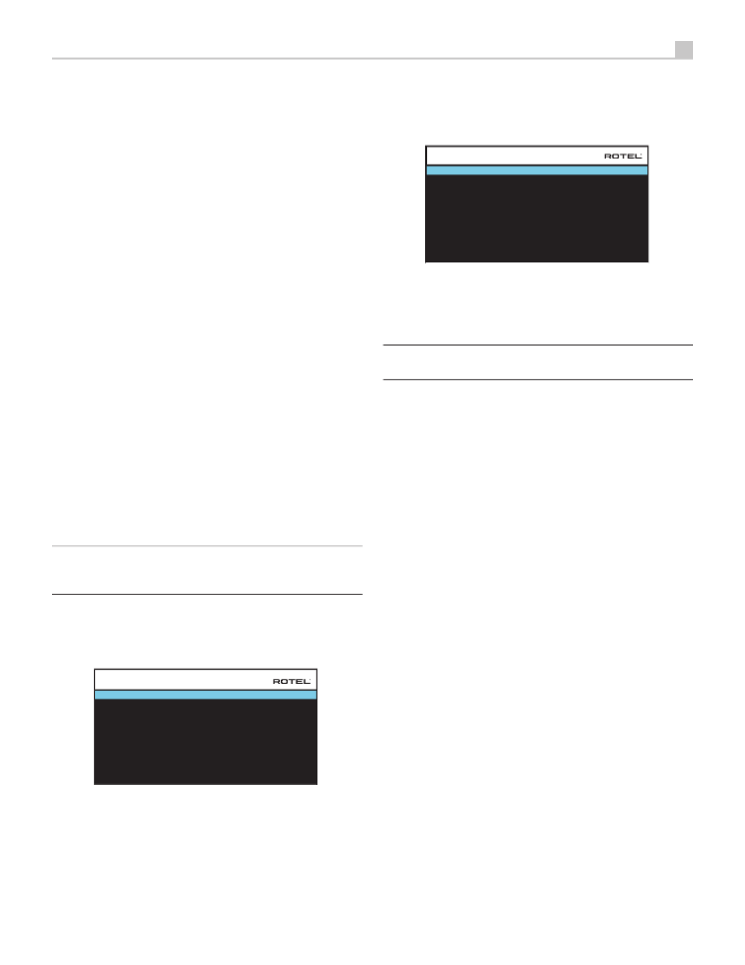
Multi Input Setup
SOURCE : MULTI INPUT
NAME : M-INPUT
VIDEO INPUT : HDMI1
TRIGGER OUTPUT : 1 _ _
LEVEL ADJUST : 0dB
BACK
INPUT SETUP
When the MULTI INPUT source is selected on the INPUT SETUP menu, the
available options change to reflect the fact that these inputs are direct analog
inputs and bypass the unit’s digital processing. The AUDIO INPUT, DEFAULT
MODE and AUDIO DELAY options are not available since these functions
are processed digitally and not available to the MULTI INPUT source.
Configuring Audio
Audio Conguration
FRONT : Front
CENTER : Center
SURROUND : Surround
SUBWOOFER : Subwoofer
CENTER BACK : Center Back
HEIGHT 1 : Ceiling Front
HEIGHT 2 : Ceiling Rear
BACK
AMPLIFIER SETUP : 7.1.4
AUDIO CONFIGURATION
The AUDIO CONFIGURATION menu configures the amplier and preamplier
RCA outputs. The screen provides options from 5.1 to 7.1.4 and an option
for 5.1 with Bi-Amplication. After selecting the desired conguration the
speaker outputs and preamplier RCA output audio signals connections
are displayed for up to 12 channels.
NOTE: Some outputs are only available via the preamplifier RCA
outputs and require an external amplifier.
Configuring Speakers and Audio
This section of the setup process covers items concerning audio reproduction
such as the number of speakers, bass management including subwoofer
crossovers, establishing equal output levels for all channels, delay settings,
and parametric EQ.
Understanding Speaker Configuration
Home theater systems vary in the number of speakers and the bass capabilities
of those speakers. This processor offers surround modes tailored to systems
with various numbers of speakers and bass management features which send
bass information to the speaker(s) best able to handle it – subwoofers and/
or large speakers. For optimum performance, you must tell the processor
the number of speakers in your system and how bass should be distributed
among them.
The following configuration instructions refer to LARGE and SMALL speakers,
referring more to their desired bass configuration than their physical size.
Specically, use the LARGE setting for speakers that you want to play deep
bass signals. Use the SMALL designation for speakers that would benefit
from having their bass sent to more capable speakers. The bass management
system redirects bass information away from all SMALL speakers and sends
it to the LARGE speakers and/or the SUBWOOFER. It may be useful to think
of LARGE as “full-range” and SMALL as “high-pass filtered.”
• Five LARGE speakers and subwoofer: This system requires no bass
redirection. All five speakers play the normal bass recorded in their
respective channels. The subwoofer plays the normal channel bass.
Meanwhile the normal bass places higher demands on the capabilities
of the other speakers and the ampliers driving them.
• LARGE front, center, surround speakers, no subwoofer: The normal
bass from the front, center, and surround channels is played in its
respective speakers.
• All SMALL speakers and subwoofer: The normal bass from all channels
is redirected to the subwoofer. The subwoofer handles ALL of the bass
in the system. This configuration provides several benefits: deep bass

24 RAP-1580 Surround Amplied Processor
is played by the speaker most suited to do so, the main speakers may
play louder with less distortion, and the need for amplier power is
reduced. This configuration should be used with bookshelf-size or
smaller main speakers. It should also be considered in some cases
with floorstanding front speakers. This configuration is advantageous
when driving the system with moderate power ampliers.
• LARGE front speakers, SMALL other speakers, and a subwoofer: The
normal bass from the SMALL center and surround speakers is redirected
to the LARGE front speakers and the subwoofer. The LARGE front
speakers play their own normal bass plus the redirected bass from
the SMALL speakers. The subwoofer plays the redirected bass from
all of the other channels. This might be an appropriate configuration
with a pair of very capable front speakers. A potential disadvantage
with mixed LARGE and SMALL congurations is that the bass response
may not be as consistent from channel to channel as it might be with
the all SMALL configuration.
Speaker Conguration
FRONT : Large
CENTER : Large
SURROUND : Large
SUBWOOFER : Yes
CEILING REAR : Large
ADVANCED SETUP
BACK
CENTER BACK : 2 Large
CEILING FRONT : Large
SPEAKER CONFIGURATION
The SPEAKER CONFIGURATION menu is used to configure the RAP-1580 for
use with your specific loudspeakers and to determine the bass management
configuration as described in the previous overview. The menu is accessed
from the MAIN menu. The Audio Conguration will determine which speakers
are displayed in the Speaker Conguration menu.
The following speaker options are available:
FRONT SPEAKERS (Small/Large): Use the “Large” setting to have the front
speakers play low bass (full-range). Use the “Small” setting to redirect
normal bass away from these speakers to a subwoofer (high-pass filtered).
CENTER SPEAKER(S) (Large/Small/None): Select the “Large” setting (not
available with SMALL front speakers) to have the center speaker play low
bass (full-range). Select the “Small” setting if your center channel speaker
has limited low frequency capability, or if you prefer that the bass be sent
to the subwoofer (high-pass). Select the “None” setting if your system does
not have a center channel speaker (the surround modes will automatically
divide all center channel information equally between the two front speakers,
creating a phantom center channel).
SURROUND SPEAKERS (Large/Small/None): Select the “Large” setting (not
available with SMALL front speakers) to have the surround speakers play
low bass (full-range). If your rear speakers have limited bass capability
or if you would prefer that the bass go to a subwoofer, select the “Small”
setting (high-pass). If your system has no rear surround speakers, select the
“None” setting (surround channels are added to the front speakers so none
of the recording is lost).
SUBWOOFER (Yes/Max/No): The “Yes” setting is the standard setting if your
system has a subwoofer. If your system does not have a subwoofer, select
“No”. Select the “Max” setting for maximum bass output with normal bass
being duplicated by both the subwoofer and any LARGE speaker in the system.
CENTER BACK (1Large/1Small/2Large/2Small/None): Some systems have
one or two additional center back surround speakers. Select the “Large”
setting (not available with S front and surround speakers) to have MALL
your center back speaker(s) play low bass. Use “1Large” if you have one
center back speaker (6.1) or “2Large” (7.1) if you have two center back
speakers (7.1). If your center back speakers have limited bass capability or
if you would prefer that the bass go to a subwoofer, use the “Small” setting
(“1Small” for one speaker, “2Small” for two speakers). If your system has
no center back speakers, select the “None” setting.
CEILING FRONT (Large/Small/None): Select the “Large” setting (not available
with SMALL front and surround speakers ) to have your top front speakers
play low bass. If you would prefer that the bass go to a subwoofer, use
the “Small” setting.
CEILING REAR (Large/Small/None): Select the “Large” setting (not available
with SMALL front , top front and surround speakers ) to have your top rear
speakers play low bass. If you would prefer that the bass go to a subwoofer,
use the “Small” setting.
ADVANCED: Speaker configuration is generally a global setting for all surround
modes and need only be done once. However, for special circumstances,
the processor provides the option of setting the speaker configuration
independently for each surround mode. Select the ADVANCED SETUP line
on the menu and press ENTER to go to the ADVANCED SPEAKER SETUP
menu described in the following section.
To change a setting on the SPEAKER CONFIGURATION menu, place the
highlight on the desired line using the Up/Down arrow buttons and use the
Left/Right arrow buttons to toggle through the available settings. To return to
the MAIN menu, select “BACK” on the OSD and press the ENTER button,
or press the BACK button. Press the SETUP/MENU button, or select “EXIT”
on the OSD to exit setup and return to normal operation.
Advanced Speaker Setup
SPEAKER : Front
CROSSOVER : 100Hz
DOLBY : Default
DTS : Default
STEREO : Default
BACK
ADVANCED SPEAKER SETUP
In most cases, the standard speaker configuration described above is a global
setting and can be used for all surround modes. However, the processor
provides the capability to customize these settings for three different modes:
Dolby, DTS, and Stereo. In addition, the ADVANCED SPEAKER SETUP
allows you to select a customized high-pass crossover frequency for the
front, center, surround, surround back speakers.
NOTE: In most systems, the default settings on this menu will provide
the most predictable results and most users will not need to change
any settings. You should fully understand bass management and have
a specific reason for needing a custom configuration before changing
these settings. Otherwise, skip to the following topic, SUBWOOFER
SETUP.

25
The available settings on the ADVANCED SPEAKER SETUP menu are as follows:
SPEAKER (Front/Center/Surround/Center back/Ceiling Front/Ceiling Rear/
Subwoofer): Select the set of speakers to be configured with custom settings.
CROSSOVER (40Hz/50Hz/60Hz/70Hz/80Hz/90Hz/100Hz/120Hz/150Hz
/200Hz/OFF): This setting for the high-pass and low-pass crossover point is
only active for SMALL speakers settings and the subwoofer. When you first
access the ADVANCED SPEAKER SETUP menu, the current crossover point
will be shown on this line which is set to “100Hz” as the factory default.
Change the value of this line only if you want the current speaker to have a
different crossover point. This setting ONLY affects redirected bass.
NOTE: The “OFF” setting (available only for the subwoofer) sends
a full-range signal to your subwoofer so that you can use its built-in
low-pass filter.
NOTE: When a speaker is set to “Large” on the SPEAKER CONFIGURATION
menu or on this menu, the crossover setting has no effect since, by
definition, a LARGE speaker plays full-range with no bass redirection to
the subwoofer and no crossover. In addition, the CROSSOVER setting
is not available for the MULTI INPUT.
DOLBY (Default/Large/Small/None): Sets the current speaker (shown in the
first line) to Large, Small, or None, overriding the setting from the SPEAKER
SETUP menu. If you want to use the speaker size setting set in the SPEAKER
SETUP menu, select “Default”. The “None” setting is not available for
FRONT speakers.
DTS (Default/Large/Small/None): The same options described for Dolby
above, except these settings ONLY take effect with DTS decoding.
STEREO (Default/Large/Small/None): The same options described for Dolby
above, except these settings ONLY take effect in STEREO surround mode.
For the subwoofer, the above selections for DOLBY, DTS and Stereo modes
become “Yes/No/Default”. If the front speakers are set to “Default” the
subwoofer will also set to “Default”. If the front speakers are small, the
subwoofer will automatically set to “Yes”.
NOTE: When the front speakers are set to use the default settings on
the ADVANCED SPEAKER menu, the specific “Large/Small/ SETUP
None” settings of DOLBY, DTS or STEREO are not available for the
other speakers. These speakers will use the default settings.
Subwoofer Setup
DOLBY : 0dB
DTS : 0dB
STEREO : 0dB
MULTI LPCM : 0dB
MULTI INPUT : 0dB
BACK
SUBWOOFER SETUP
These five lines allow you to override the subwoofer level setting as
determined in the Speaker Level Setup menu (see next section) for each
specic surround mode.
DOLBY:
DTS:
STEREO:
MULTI LPCM:
MULTI INPUT:
Use the Up/Down arrow buttons to move to the specic surround mode and
use the Left/Right arrow buttons to adjust the subwoofer level for the current
surround mode. The options are a range of adjustments from -9 dB to +9
dB and MAX (+10 dB). A setting of 0 dB means that the specified surround
mode will use the master subwoofer level. Any other setting is an offset to
the master setting. For example, an adjustment of -2 dB for a particular
surround mode means that the subwoofer level will be 2 dB quieter than
the master subwoofer level when that surround mode is selected. Use these
subwoofer level settings to adjust the relative bass output of various surround
modes. Changing the master subwoofer level will increase or decrease the
level for all surround modes.
We recommend starting with the settings for all surround modes at the
default 0 dB setting during the speaker level calibration of the system and
for a period of familiarization after that. As you listen to a variety of source
material over time, you may notice that certain surround modes consistently
produce too much or too little bass from the subwoofer. If so, then use these
menu settings to customize each surround mode. In general, if the master
subwoofer level is set properly (i.e. not too loud), individual settings for
each surround mode should not be necessary.
To return to the main menu select “BACK” on the OSD or push the BACK
button on the remote control or front panel.
Speaker Level Setup
FRONT LEFT : 0dB
CENTER : 0dB
FRONT RIGHT : 0dB
SURROUND RIGHT : 0dB
CENTER BACK RIGHT : 0dB
CENTER BACK LEFT : 0dB
SURROUND LEFT : 0dB
SUBWOOFER : 0dB
BACK
CEILING FRONT RIGHT : 0dB
CEILING REAR RIGHT : 0dB
CEILING REAR LEFT : 0dB
CEILING FRONT LEFT : 0dB
SPEAKER LEVEL SETUP
NOTE: If you have configured your system to use two center back
speakers, there will be an additional line in the menu, giving you the
ability to independently adjust the CENTER BACK LEFT and CENTER
BACK RIGHT speakers.
This menu uses filtered noise test tones to set equal volume levels for all
speakers (FRONT LEFT, CENTER, FRONT RIGHT, SURROUND RIGHT, CENTER
BACK RIGHT, CEILING FRONT RIGHT, CEILING REAR RIGHT, CEILING REAR
LEFT, CEILING FRONT LEFT, CENTER BACK LEFT, SURROUND LEFT and
SUBWOOFER) to ensure proper surround sound reproduction. Setting the
output levels using the test procedure provides the most accurate adjustment
so that digital surround sound material will be reproduced as it was intended
and is a critical step in calibrating the system. The Audio Conguration will
determine which speakers are displayed in the Speaker Level Setup menu.
When you enter the SPEAKER LEVEL SETUP menu, you will hear a test tone
coming from the highlighted speaker. Highlight different speakers by moving
the cursor to the desired line using the Up/Down arrow buttons. The test
tone will shift accordingly to the selected speaker.

26 RAP-1580 Surround Amplied Processor
Seated in the normal listening location, shift the test tone to the various
speakers. Using the one speaker as a reference, listen for any speakers that
are noticeably louder or quieter. If so, adjust that speaker’s levels up or down
(in 0.5 dB increments) using the Left/Right arrow buttons. Continue switching
among the speakers and adjusting until all speakers are the same volume.
To return to the MAIN menu, select “BACK“ on the OSD or press the BACK
button. Press the SETUP/MENU button or select “EXIT“ on the OSD to exit
setup and return to normal operation.
Calibration with an SPL meter:
Calibrating the system with an SPL (Sound Pressure Level) meter, rather than
by ear, provides more precise results and improves the system’s performance
signicantly. Inexpensive SPL meters are widely available and the procedure
is quick and easy.
Both Dolby and DTS specify a standard calibration level for all theaters to
ensure that soundtracks can be played at the volume level intended by the
director of the film. This reference level should result in spoken dialog played
at a realistic level for normal speech with the loudest peaks in any single
channel at about 105 dB. The RAP-1580’s test tones are generated at a
precise level (-30 dBFs) relative to the loudest possible digitally recorded
sound. At the Dolby or DTS reference level, these test tones should produce
a 75 dB reading on an SPL meter.
Set the meter to its 70 dB dial setting with SLOW response and C-weighting,
held away from your body at your listening position (mounting the SPL
meter on a camera tripod makes this easier). You can point the SPL meter
at each speaker as it is being measured; however, positioning the meter
in a fixed position pointing at the ceiling is easier and probably produces
more consistent results.
Increase the master volume control on the unit until the meter reads 75 dB
(+5 dB on the meter scale) when playing the test tone through one of the
front speakers. Then, use the individual channel adjustments on the SPEAKER
LEVEL SETUP menu to adjust each of the individual speakers, including the
subwoofer, to the same 75 dB on the SPL meter.
NOTE: Due to meter weighting curves and room effects, the actual
level of the subwoofer may be slightly higher than you measure. To
compensate, Dolby suggests setting the subwoofer several dB lower
when calibrating with an SPL meter (i.e. set the subwoofer to read 72
dB on the meter instead of 75 dB). Ultimately, the proper subwoofer
level must be determined by personal taste and some listeners prefer
to set it above 75 dB for film soundtracks. Exaggerated bass effects
come at the expense of proper blending with the main speakers and
place stress on the subwoofer and its amplifier. If you can localize
bass from the subwoofer, the subwoofer level may be too high. Music
can be useful for fine-tuning the subwoofer level as excessive bass is
readily apparent. The proper setting will generally work well for music
and movie soundtracks.
Remember the setting of the master volume control used during this calibration.
To play a Dolby Digital or DTS soundtrack at the reference volume level,
simply return to that volume setting. Note that most home theater listeners
find this setting to be excessively loud. Let your own ears be the judge for
deciding how loud to playback movie soundtracks and adjust the master
volume control accordingly. Regardless of your listening levels, using an SPL
meter to calibrate equal levels for all speakers in the system is recommended.
Speaker and Delay/Distance Setup
FRONT LEFT : 10.00 FT 3.05M
CENTER : 10.00 FT 3.05M
FRONT RIGHT : 10.00 FT 3.05M
SURROUND RIGHT : 10.00 FT 3.05M
CENTER BACK RIGHT : 10.00 FT 3.05M
CENTER BACK LEFT : 10.00 FT 3.05M
SURROUND LEFT : 10.00 FT 3.05M
SUBWOOFER : 10.00 FT 3.05M
BACK
CEILING FRONT RIGHT : 10.00 FT 3.05M
CEILING REAR RIGHT : 10.00 FT 3.05M
CEILING REAR LEFT : 10.00 FT 3.05M
CEILING FRONT LEFT : 10.00 FT 3.05M
SPEAKER DISTANCE SETUP
The SPEAKER DISTANCE SETUP menu, which is reached from the MAIN
menu, allows you to set the delay for individual speakers. This ensures that
the sound from each speaker arrives simultaneously at the listening position,
even when the speakers are not all placed at equal distances from the
listener. Increase the delay to speakers located closer to the seating area
and decrease the delay to speakers located farther from the seating area.
The Audio Conguration will determine which speakers are displayed in
the Speaker Distance Setup menu.
This Rotel processor makes setting the delay time for each speaker very
easy. Simply measure the distance (in feet or meters) from your seating
position to each speaker in your system. Set the measured distance in the
line for each speaker. The menu provides a line for each speaker configured
in your system and gives a range of settings up to 33 feet (10.6 meters)
in 0.25 foot (0.075 m) increments with each increment equivalent to an
additional delay of 0.25 ms.
To change a setting, place the highlight on the desired line using the Up/
Down arrow buttons and use the Left/Right arrow buttons to increase or
decrease the delay. To return to the MAIN menu, press the BACK button or
select “BACK“ on the OSD. Press the SETUP/MENU button or select “EXIT“
on the OSD to exit setup and return to normal operation.
Miscellaneous Settings
System Setup
LANGUAGE : English
IR REMOTE CODESET : Codeset 1
PEQ FUNCTION : Disable
DISPLAY : HDMI and TFT
TFT BRIGHTNESS : 0
NETWORK CONFIGURATION
SOFTWARE INFORMATION
RESTORE FACTORY DEFAULT
BACK
POWER OPTION
NETWORK WAKEUP : Disable
SYSTEM SETUP
This SYSTEM SETUP menu, reached from the MAIN menu, provides access
to several miscellaneous settings as follows:
LANGUAGE: Selects a language for the On Screen Display.
IR REMOTE CODESET: The RAP-1580 has two IR codesets and can be
changed in the event there is a conict of IR codes with other Rotel products.
NOTE: After changing the IR REMOTE CODESET the remote must
also be changed to continue using the remote control. Push and hold
the TUNER button and 1 (or TUNER and 2 for codeset 2) at the same
time and hold for approximately 5 seconds until the backlights on the

27
remote control blink on then off then release both buttons. This sets the
remote control to use codeset 1 (or codeset 2 if TUNER and 2 are held).
PEQ FUNCTION: Turns the PEQ function On or Off.
DISPLAY: Sets the information shown on the main HDMI OSD and front TFT
display. Settings are “Off”, “HDMI Only”, “TFT Only“ or “HDMI And TFT”.
TFT BRIGHTNESS: Sets the brightness of the front TFT display. Settings range
from -10 to +10.
NETWORK WAKEUP: Enables or Disables power on and power off via the
network connection. Enable this function for use with automation systems
using IP control.
NOTE: When Network Wakeup is configured to enabled, the RAP- 1580
will consume additional power in standby mode.
POWER OPTION: Access to conguration of Auto Power Down Timer, Max
Power On Volume, Power Mode and Signal Sense Input.
AUTO POWER DOWN TIMER : Disable
BACK
MAX POWER ON VOLUME : 45
SIGNAL SENSE INPUT : Disable
POWER MODE : Normal
POWER OPTION
AUTO POWER DOWN TIMER: Sets the amount of time the units stays
powered on when there is no audio signal. The RAP-1580 will
automatically go to standby mode if audio is not detected for the
specied timer period.
Valid settings include: Disable, 1 Hour, 2 Hours, 4 Hours.
MAX POWER ON VOLUME: Species a maximum volume level to be
used each time the unit powered on, between 20 dB to 70 dB, in 1
dB increments.
POWER MODE: Enables the RAP-1580 to be controlled via the network
port when attached to an automation system. This option also allows
the rear panel USB power port to remain powered at all times. The
power consumption is higher in Quick Power mode. If network control
is not required select the Normal Power mode. To enable IP automation
controls or continuous power to the rear USB power port select the
Quick option. This function is similar to the Network Wake Up option.
“Normal” is the factory default.
Valid settings include: Normal, Quick.
NOTE: When the POWER MODE is configured to Quick, the RAP- 1580
will consume additional power in standby mode.
SIGNAL SENSE INPUT: Checks if a digital audio signal is present on
the congured Signal Sense Input. When this input is selected as the
active listening source, the RAP-1580 monitors the digital data stream to
determine if there is audio. If there is no audio detected for 10 minutes,
the RAP-1580 will enter Signal Sense Standby Mode. When in Signal
Sense Standby Mode and the RAP-1580 detects audio on Signal Sense
Input, the unit will automatically power on. To disable this function, select
the DISABLE option which is the factory default setting.
NOTE: To use the Signal Sense function, the RAP-1580 must be actively
listening to the configured Signal Sense source. If a source other than
the configured Signal Sense source is selected, the automatic power
off and power on functions will not be active. Example: if the Signal
Sense source is configured as COAX 1 and the unit is listening to OPT
2, the signal sense functions will not be activated.
NOTE: When the RAP-1580 enters standby mode via the remote
control, the Signal Sense function will not operate until the unit detects
the audio has stopped for the minimum 10 minute time-out period. This
prevents the unit from immediately powering back on if there is still
active audio playing.
NOTE: When the SIGNAL SENSE INPUT function is activated, the RAP-
1580 will consume additional power in signal sense standby mode.
NETWORK CONFIGURATION: Sets the network conguration for the unit. In
most systems, set the IP ADDRESS MODE to DHCP. This setting will allow
your router to assign an IP address to the RAP-1580 automatically. If your
network uses xed IP addresses, set the IP ADDRESS MODE to Static. A
xed or STATIC IP address requires manually entering the IP Address, Subnet
Mask, Gateway, and DNS in the IP ADDRESS CONFIGURATION sub menu.
IP ADDRESS MODE : DHCP
RENEW DHCP IP ADDRESS
VIEW NETWORK SETTINGS
TEST NETWORK CONNECTION
BACK
NETWORK CONFIGURATION
SOFTWARE INFORMATION: Displays the current software installed in the
unit. It shows the MAIN, DSP and STANDBY software versions. There is also
an option to check for software updates. This feature lets the unit search
for software updates on the Internet. The network needs to be properly
congured. Alternatively, you can load the software through the front USB
socket. For more information on the software update process please contact
your authorized Rotel dealer.
RESTORE FACTORY DEFAULT: This option sets the unit back to the original
setting as when it left the factory. All user setting will be erased.
NOTE: Use caution when resetting the RAP-1580 to factory defaults as
all use configured options will be erased and reset to original factory
settings.
Video Setup
STANDBY VIDEO SOURCE : Disable
BACK
AUIDO MODE : Pre-Output Enabled
VIDEO SETUP

28 RAP-1580 Surround Amplied Processor
The VIDEO SETUP menu provides configuration of the HDMI outputs. See
the HDMI INPUTS & OUTPUTS section of this manual for details on HDMI
connections.
AUDIO MODE: Options are “HDMI Audio Output Only” or “Pre-Output
Enabled”. In “HDMI Audio Output Only” setting, the HDMI audio input is
sent to the TV via the HDMI cable, the audio will be from the TV’s speakers.
Set to “Pre-Output Enabled” mode to play the HDMI audio input through
the RAP-1580 RCA or speaker outputs .
NOTE: When configured for “HDMI Audio Output Only” no HDMI
audio input will be sent from the RAP-1580 RCA or speaker outputs.
HDMI inputs sound is only available on the attached TV display.
STANDBY VIDEO SOURCE: Options are “Disable”, “HDMI 1-7”, “HDMI
Front”, or “Last”. This allows the selected HDMI source input to pass-through
the RAP-1580 while in standby mode. Audio and video are passed directly
to the attached TV or display.
NOTE: When the Standby Video Source is enabled the RAP-1580 will
consume additional power when in standby mode.
Press the BACK button or select “BACK“ on the OSD to exit the VIDEO
SETUP Menu and return to the main menu.
PEQ Conguration
SPEAKER : Front Le
BACK
FREQUENCY : 20Hz
FREQUENCY : 40Hz Q : 1 GAIN : 0
FREQUENCY : 60Hz Q : 1 GAIN : 0
FREQUENCY : 120Hz Q : 1 GAIN : 0
FREQUENCY : 200Hz Q : 1 GAIN : 0
FREQUENCY : 500Hz Q : 1 GAIN : 0
FREQUENCY : 1,200Hz Q : 1 GAIN : 0
FREQUENCY : 4,000Hz Q : 1 GAIN : 0
FREQUENCY : 12,000Hz Q : 1 GAIN : 0
FREQUENCY : 20,000Hz GAIN : 0
GAIN : 0Q : 1
Q : 1
PEQ CONFIGURATION
The PEQ CONFIGURATION menu allows you to enter EQ values for 10
bands as shown. PEQ setup requires advanced knowledge and equipment
for measuring the frequency response of the room and performance of the
speakers. To properly congure the EQ you should be familiar with the
tools and equipment needed. Typically these settings are only changed
by professional installers to ensure optimal performance of the RAP-1580.
Use the navigations buttons to highlight the frequency: Push the ENTER
button on the remote control or front panel to access and make changes.
Use the Up/Down arrow buttons to change the value. Use the Left/Right
arrow buttons to move to the next section on the line. Press ENTER again
to conrm settings and allow navigation to the next PEQ BAND. The Audio
Conguration will determine which speakers are available for conguration
in the PEQ Conguration menu.
FREQUENCY: There are 10 bands available and the frequency can be
changed between 10 - 24kHz as below.
BAND 1 Freq: 10Hz - 40Hz, 1Hz Step Default 20Hz
BAND 2 Freq: 20Hz - 44Hz, 1Hz Step Default 40Hz
BAND 3 Freq: 45Hz - 89Hz, 1Hz Step Default 60Hz
BAND 4 Freq: 90Hz - 180Hz, 10Hz Step Default 120Hz
BAND 5 Freq: 190Hz - 350Hz, 10Hz Step Default 200Hz
BAND 6 Freq: 360Hz - 690Hz, 10Hz Step Default 500Hz
BAND 7 Freq: 700Hz - 1900Hz, 100Hz Step Default 1.2kHz
BAND 8 Freq: 2kHz - 7.78kHz, 100Hz Step Default 4kHz
BAND 9 Freq: 8kHz - 20kHz, 100Hz Step Default 12kHz
BAND 10 Freq: 8kHz - 24kHz, 100Hz Step Default 20kHz
Q: The Q value can be adjusted between 1 to 10.
GAIN: The gain can be set between -12 to +2.
To exit this menu press the BACK button or select “BACK“ on the OSD then
press the SETUP/MENU button to return to normal operations.
NOTE: Q in EQ value relates to the bandwidth of the filter. The higher
the value, the narrower the bandwidth.
Troubleshooting
Most difculties in audio systems are the result of incorrect connections, or
improper control settings. If you encounter problems, isolate the problem
area, check the control settings, determine the cause of the fault and make
the necessary changes. If you are unable to get sound from the unit, refer
to the suggestions for the following conditions:
The unit does not turn on
• Make sure the power cord is plugged into the rear panel and a AC outlet.
• Make sure the rear panel POWER switch is in the ON position.
No sound from any input
• Make sure that MUTING is off and VOLUME is turned up.
• If not using the RAP-1580’s internal power amp channels, make sure
that the pre-amp outputs are connected to a power amplier and that
the amplier is powered on.
• Make sure that any speakers are connected correctly.
• Make sure source inputs are connected and configured correctly.
• Check that the setting for AUDIO MODE in the VIDEO SETUP menu
is set to “Pre-Out Enable”.
No sound from digital sources
• Make sure that digital input connector is assigned to the proper source
input and that the source input is configured to use the digital input
rather than an analog input.
• Check the configuration of the digital input source player to ensure
that the digital output is activated.
No sound from some speakers
• Check all power amp and speaker connections.
• Check Speaker Configuration settings in the Setup menus.
No Video Output
• Make sure that the TV monitor is connected properly and check the
input assignments.
• Check the source input and TV output resolution are compatible. A 4K
source can only be sent to a 4K monitor.

29
• HDMI cables must be 5 meters or less in length.
• If watching 3D source, make sure the display is 3D enabled.
Video and Audio do not match.
• Check that the proper video source is selected for each input.
• Check that the group delay (lip-synch) setting is not mis-adjusted.
Clicking or popping sounds when switching inputs
• The unit uses relay switching to preserve maximum sound quality. The
mechanical clicking of the relays is normal.
• Switching between HDMI sources may cause delays as HDMI two way
communications “handshake” must be established between the source
and display. The time required for the handshake varies depending
on the attached equipment.
Controls do not operate
• Make sure that fresh batteries are installed in the remote.
• Make sure that the IR sensor on the front panel is not blocked. Aim the
remote control at the sensor.
• Make sure the sensor is not receiving strong IR light (sunlight, halogen
lighting, etc.).
• Unplug the unit from the AC outlet, wait 30 seconds, and plug it
back to reset.
• Conrm the IR Codeset set in the remote control and RAP-1580 are
matched to either Codeset 1 or Codeset 2.

30 RAP-1580 Surround Amplied Processor
Specications
Audio
Continuous Power Output 100 watts / channel
(20 - 20k Hz, THD 0.05%, 8 ohms)< 7 channels driven
Continuous Power Output 150 watts / channel
(1k Hz, THD 0.03%, 8 ohms)< 2 channels driven
Total Harmonic Distortion < 0.03%
Intermodulation Distortion < 0.03%(60 Hz : 7 kHz, 4:1)
Frequency Response
Phono Input 20 Hz - 20k Hz, ± 1 dB
Analog Bypass 10 Hz - 100k Hz, ± 1 dB
Digital Input 20 Hz - 20k Hz, ± 0.5 dB
Damping Factor 230(1k Hz, 8 ohms)
Signal to Noise Ratio (A-weighted)
Analog Bypass 100 dB
Digital Input 96 dB
Input Sensitivity/Impedance
Phono Level 3.85 mV / 47k ohms
Line Level 300 mV / 100k ohms
Balance Level 600 mV / 100k ohms
Preamp Output Level 1.2 V
Digital Audio LPCM (up to 192kHz, 24-bit)
Dolby® Surround,
Dolby® TrueHD,
Dolby® ATMOS,
DTS-HD Master Audio,
DTS X
Video
Input Resolutions 480i/576i, 480p/576p, 720p,
1080i, 1080p, 1080p 24Hz,
3D, 4K, UHD
Output Resolution 480i/576i, 480p/576p, 720p
1080i, 1080p, 1080p 24Hz,
3D, 4K, UHD
Color Space Support sRGB, YCbCr 4:2:2, YCbCr 4:4:4
Deep Color Support 24-bit, 30-bit, 36-bit
HDMI Inputs/Outputs 8 inputs with 3 supporting HDCP 2.2
2 outputs supporting HDCP 2.2
Audio Return Channel
General
Power Consumption 1100 watts
< 0.5 watt (standby)
Power Requirements ) 120 volts, 60Hz (AC
230 volts, 50Hz
BTU ) 2800 BTU/h(4 ohms. 1/8 Power
Dimension 431 x 192 x 470 mm(W x H x D)
17 x 7 5/ x 18 91/ in2
Front Panel Height 4U / 177 mm / 7 in
Weight 22.8 kg / 50.27 lbs
All specifications are accurate at the time of printing. Rotel reserves the right to make
improvements without notice.
Rotel and the Rotel Hifi logo are registered trademarks of The Rotel Co., Ltd. Tokyo, Japan.
“Made for iPod,” and “Made for iPhone,” means that an electronic accessory
has been designed to connect specically to iPod or iPhone, respectively, and
has been certied by the developer to meet Apple performance standards. Apple
is not responsible for the operation of this device or its compliance with safety
and regulatory standards. Please note that the use of this accessory with iPod,
or iPhone may affect wireless performance.
iPhone, iPod, iPod classic, iPod nano, and iPod touch are trademarks of Apple
Inc., registered in the U.S. and other countries.

31
Français
Vue d’ensemble de la façade 39 . . . . . . . . . . . . . . . . . . . . . . . . . . . . . . . . . . . . . . . . . .
Afcheur en face avant 393
Capteur de télécommande 392
Vue d’ensemble de la télécommande 40 . . . . . . . . . . . . . . . . . . . . . . . . . . . . . . . . . . . .
Vue d’ensemble des touches et des commandes 40 . . . . . . . . . . . . . . . . . . . . . . . . . . . .
Touche STANDBY et Touche POWER ON/OFF 401 A
Bouton de VOLUME et Touche VOLUME +/- 404D
Bouton AFFICHAGE (DISPLAY) 40=B
Bouton MENU/SETUP 407H
Touches de Navigation et de Sélection (FONCTION) 405I
Touche MUTE 40qF
Boutons INPUT 406M
SUR+ 40-B
Boutons de contrôle de lecture 40L
Bouton DIM 40J
Boutons SUB, CTR et REAR 40B
Bouton MEM 41E
Bouton LIGHT 41N
ASSISTIVE LIGHT 41O
Modes surround automatiques 41 . . . . . . . . . . . . . . . . . . . . . . . . . . . . . . . . . . . . . . . .
Sélection manuelle des modes surround 41 . . . . . . . . . . . . . . . . . . . . . . . . . . . . . . . . . .
Audionumérique 41
Stéréo analogique 41
Fonctions de base 42 . . . . . . . . . . . . . . . . . . . . . . . . . . . . . . . . . . . . . . . . . . . . . . . . . .
Sélection des entrées 42
Fonctionnement USB/iPod 42 . . . . . . . . . . . . . . . . . . . . . . . . . . . . . . . . . . . . . . . . . . .
Connexion d’un iPod ou d’un iPhone 420
Boutons de lecture 42L
Bluetooth. . . . . . . . . . . . . . . . . . . . . . . . . . . . . . . . . . . . . . . . . . . . . . . . . . . . . . . . 42
Connexion Bluetooth 42
Prise USB arrière 42 . . . . . . . . . . . . . . . . . . . . . . . . . . . . . . . . . . . . . . . . . . . . . . . . . .
Connexion à la prise USB arrière 42
CONFIGURATION 42 . . . . . . . . . . . . . . . . . . . . . . . . . . . . . . . . . . . . . . . . . . . . . . . . . .
Menus de base 42 . . . . . . . . . . . . . . . . . . . . . . . . . . . . . . . . . . . . . . . . . . . . . . . . . . . .
Touches de navigation 42
Menu Principal (Main Menu) 43
Configuration des Entrées 43 . . . . . . . . . . . . . . . . . . . . . . . . . . . . . . . . . . . . . . . . . . . .
Conguration des Entrées (Input Setup) 43
Conguration de l’entrée Multi 44
Configuration de Audio 44 . . . . . . . . . . . . . . . . . . . . . . . . . . . . . . . . . . . . . . . . . . . . . .
Conguration de Audio (Auido Setup) 44
Configuration des Enceintes et de la partie Audio 45 . . . . . . . . . . . . . . . . . . . . . . . . . . .
Conguration des enceintes 45
Conguration Avancée des Enceintes 46
Conguration du caisson de graves 47
Réglage des niveaux des enceintes 47
Réglage des distances/retard des enceintes 48
Réglages Divers 48 . . . . . . . . . . . . . . . . . . . . . . . . . . . . . . . . . . . . . . . . . . . . . . . . . . .
Conguration Système (System Setup) 48
Conguration Vidéo 50
Egalisation PEQ 50
Résolution des pannes 51 . . . . . . . . . . . . . . . . . . . . . . . . . . . . . . . . . . . . . . . . . . . . . .
Spécifications 52 . . . . . . . . . . . . . . . . . . . . . . . . . . . . . . . . . . . . . . . . . . . . . . . . . . . . .
Sommaire
Figure 1 : Commandes et Connexions 5
Figure 2 : Télécommande 6
Figure 3 : Amplicateurs et caissons de graves 7
Figure 4 : Connexion de haut-parleur 8
Figure 5 : Connexions audio numériques et PC-USB 9
Figure 6 : Connexions à un lecteur Blu-Ray ou Vidéo 9
Figure 7 : Connexions USB en face avant 10
Figure 8 : Connexions à un lecteur de CD 10
Figure 9 : Connexions à un tuner 11
Figure 10 : Connexions HDMI avant 11
Figure 11 : Connexions HDMI arrières 12
Afchage des menus à l’écran 13
Remarques importantes concernant la sécurité 33 . . . . . . . . . . . . . . . . . . . . . . . . . . . . .
A propos de Rotel 34 . . . . . . . . . . . . . . . . . . . . . . . . . . . . . . . . . . . . . . . . . . . . . . . . .
Mise en route 34 . . . . . . . . . . . . . . . . . . . . . . . . . . . . . . . . . . . . . . . . . . . . . . . . . . . .
Caractéristiques Vidéo 34
Caractéristiques Audio 34
Caractéristiques Surround 34
Autres caractéristiques 34
Déballage 35
Installation 35
Vue générale de la connectique 35 . . . . . . . . . . . . . . . . . . . . . . . . . . . . . . . . . . . . . . .
Entrées et sorties HDMI 35 . . . . . . . . . . . . . . . . . . . . . . . . . . . . . . . . . . . . . . . . . . . .
Entrées vidéo HDMI 1-7 arrières 35r
Entrée HDMI en face avant 359
Sorties Moniteur HDMI 35e
Entrées et sorties audio 36 . . . . . . . . . . . . . . . . . . . . . . . . . . . . . . . . . . . . . . . . . . . . .
Entrée Phono 36g
Entrée Tuner 36g
Entrée lecteur de CD 36g
Entrée Symétriques 36d
Entrée MULTI 36j
Sortie Préampli 36;
Entrées Numériques 36w
Entrée PC-USB 36t
Entrée USB en face avant 370
Autres Connexions 37 . . . . . . . . . . . . . . . . . . . . . . . . . . . . . . . . . . . . . . . . . . . . . . . . .
Prise secteur 37'
Interrupteur principal de mise sous tension 37a
Connexions 12V TRIGGER 37i
Prise jack REM IN 37o
Prises IR OUT 37p
Port USB en face arrière 37\
Prise RS-232 37y
Prise réseau 37u
CONNEXIONS 38 . . . . . . . . . . . . . . . . . . . . . . . . . . . . . . . . . . . . . . . . . . . . . . . . . . . .
Connexion à des enceintes acoustiques 38
Connexion à un amplicateur externe de puissance 38
Connexion d’un caisson de graves 38
Connexions à un lecteur DVD, Blu-ray, à une console de jeux, unrécepteur câble
ou satellite HDTV 38
Connexion à un lecteur Blu-ray ou de DVD 39
Connexion d’un moniteur 39
Connexion d’un lecteur de CD ou la source XLR 39
Connexion d’un tuner 39
Connexion d’un iPod ou iPhone 39

32 RAP-1580 Surround Amplicateur Processeur
Tous les appareils Rotel sont conçus en totale conformité
avec les directives internationales concernant les
restrictions d’utilisation de substances dangereuses
(RoHS) pour l’environnement, dans les équipements
électriques et électroniques, ainsi que pour le recyclage
des matériaux utilisés (WEEE, pour Waste Electrical
and Electronic Equipment). Le symbole du conteneur
à ordures barré par une croix indique la compatibilité
avec ces directives, et le fait que les appareils peuvent
être correctement recyclés ou traités dans le respect
total de ces normes.
DAB
RSP- 1582
DISPL M UTEAYSUR+INPUT BACKMENU
ST YANDB
FUNC TION
ENTER
HDMI
2.1
RAP- 1580
DISPL M UTEAYSUR+INPUT BACKME NU
ST YANDB
FUNC TION
ENTE R
HDMI
L’éclair dans un triangle équilatéral indique
la présence interne de tensions électriques
élevées susceptibles de présenter des
risques graves d’électrocution.
Le point d’e lamation dans un triangle xc
équilatéral indique à l’utilisateur la
présence de conseils et d’informations
importantes dans le manuel d’utilisation
accompagnant l’appareil. Leur lecture est
impérative.
Assignation des connecteurs
Audio Symétrique
(prise XLR 3 broches) :
Pin 1 : Masse/Terre
Pin 2 : Phase/+ve /Point chaud
Pin 3 : Hors Phase /-ve / Point froid
1 2
3

33
Français
ATTENTION : Il n’y a à l’intérieur aucune pièce susceptible d’être modifiée par l’utilisateur. Adressez-vous
impérativement à une personne qualifiée.
ATTENTION : Pour réduire tout risque d’électrisation ou d’incendie, ne pas exposer l’appareil à une
source humide, ou à tout type de risque d’éclaboussure ou de renversement de liquide. Ne pas poser dessus
d’objet contenant un liquide, comme un verre, un vase, etc. Prenez garde à ce qu’aucun objet ou liquide ne
tombe à l’intérieur de l’appareil par ses orifices de ventilation. Si l’appareil est exposé à l’humidité ou si
un objet tombe à l’intérieur, débranchez-le immédiatement de son alimentation secteur, et adressez-vous
immédiatement et uniquement à une personne qualifiée et agréée.
Tous les conseils de sécurité et d’installation doivent être lus.
Conservez soigneusement ce livret.
Tous les conseils de sécurité doivent être soigneusement respectés.
Respectez les procédures d’installation et de fonctionnement indiquées dans ce manuel.
Ne pas utiliser cet appareil près d’un point d’eau.
L’appareil doit être nettoyé uniquement avec un chiffon sec ou un aspirateur.
Il ne doit pas être posé sur un fauteuil, un canapé, une couverture ou toute autre surface susceptible de
boucher ses ouïes d’aération; ou placé dans un meuble empêchant la bonne circulation d’air autour des
orifices d’aération.
Cet appareil doit être placé loin de toute source de chaleur, tels que radiateurs, chaudières, bouches de
chaleur ou d’autres appareils (y compris amplificateurs de puissance) produisant de la chaleur.
Notamment, ne pas tenter de supprimer la prise de terre (troisième broche de la prise) si celle-ci est présente.
Si la prise n’est pas conforme à celles utilisées dans votre installation électrique, consultez un électricien agréé.
Prendre garde à ce que ce cordon d’alimentation ne soit pas pincé, écrasé ou détérioré sur tout son trajet,
et à ce qu’il ne soit pas mis en contact avec une source de chaleur. Vérifiez soigneusement la bonne qualité
des contacts, à l’arrière de l’appareil comme dans la prise murale.
N’utilisez que des accessoires préconisés par le constructeur.
N’utilisez que des meubles, supports, systèmes de transport recommandés par Rotel.
Procédez toujours avec la plus extrême précaution lorsque vous déplacez l’appareil,
afin d’éviter tout risque de blessure.
Débranchez le câble d’alimentation en cas d’orage, ou si l’appareil ne doit pas être utilisé pendant une
longue période.
L’appareil doit être immédiatement éteint, débranché puis retourné au service après-vente agréé dans les
cas suivants: le câble d’alimentation secteur ou sa prise est endommagé; un objet est tombé, ou du liquide
a coulé à l’intérieur de l’appareil; l’appareil a été exposé à la pluie; l’appareil ne fonctionne manifestement
pas normalement; l’appareil est tombé, ou le coffret est endommagé.
L’appareil doit être placé de telle manière que sa propre ventilation puisse fonctionner,
c’est-à-dire avec un espace libre d’une dizaine de centimètres minimum autour de lui.
ATTENTION : La prise secteur en face arrière constitue le moyen principal pour connecter/déconnecter
l’appareil de son alimentation secteur. L’appareil doit donc être installé de telle manière que ce câble
d’alimentation soit accessible en permanence.
Cet appareil doit être branché sur une prise d’alimentation secteur, d’une tension et d’un type conformes à
ceux qui sont indiqués sur la face arrière de l’appareil (USA : 120 V/60 Hz, CE : 230 V/50 Hz).
Brancher l’appareil uniquement grâce au cordon secteur fourni, ou à un modèle équivalent. Ne pas tenter
de modifier ou changer la prise. Ne pas utiliser de cordon rallonge.
La prise d’alimentation secteur constitue le moyen radical de déconnexion de l’appareil. Elle doit donc
rester en permanence accessible, car sa déconnexion constitue la seule assurance que l’appareil n’est plus
alimenté par le secteur.
La prise principale est utilisée comme dispositif de déconnexion principal et doit rester facilement accessible.
Utilisez un câble de type Classe 2 pour la liaison avec les enceintes acoustiques, afin de garantir une
installation correcte et de minimiser les risques d’électrocution.
Les piles de la télécommande ne doivent pas être exposées à une température excessive, comme l’exposition
directe au soleil, au feu ou équivalent.
ATTENTION : L’interrupteur d’alimentation principal est localisé sur le panneau arrière. L’appareil doit
donc être installé de façon à ce que l’interrupteur d’alimentation principal reste accessible.
Remarques importantes concernant la sécurité Remarque
La connexion RS-232ne concerne que des techniciens agréés uniquement.
Information FCC
Cet appareil a été testé an de vérier sa conformité avec les normes minima des appareils num
de classe B, suivant l’article 15 des normes FCC. Ces normes garantissent une protection suf
les interférences, dans le cadre d’une utilisation domestique. Cet appareil génère, utilise et peu
des fréquences radio et peut, s’il n’est pas utilisé selon les conseils prodigués dans ce manuel d
causer des interférences avec les communications radio.
Il n’y a cependant aucune garantie que ces interférences n’interviennent dans certaines instal
vous notez la présence de parasites sur la radio ou la télévision (détectées par la mise sous et h
de l’appareil), vous pouvez essayer d’éliminer ces interférences en essayant une des procédures
• Réorientez ou déplacez l’antenne de réception (TV, radio, etc.).
• Augmentez l’éloignement physique entre le récepteur en cause et l’appareil.
• Branchez les autres maillons sur une prise secteur différente de celle sur laquelle est branché le
• Consultez votre revendeur, ou un technicien spécialiste de ces questions de réception radio/T

34 RAP-1580 Surround Amplicateur Processeur
A propos de Rotel
Notre histoire commence il y a plus de 50 ans. Depuis, au l des années,
nous avons reçu des centaines de prix et de récompenses, et satisfait des
centaines de milliers de personnes – comme vous !
Rotel a été fondée par une famille passionnée de musique, qui a décidé
de fabriquer des maillons Haute Fidélité sans compromis aucun. Depuis sa
création, cette passion est restée intacte, et cette famille s’est xée comme
objectif de proposer à tous les audiophiles et mélomanes les meilleurs
appareils possibles, quel que soit leur budget. Une volonté partagée par
tous les employés de Rotel.
Les ingénieurs Rotel travaillent comme une équipe très soudée, écoutant,
peaunant chaque nouveau modèle jusqu’à ce qu’il atteigne exactement
leurs standards – très élevés – de musicalité. Ils sont libres de choisir des
composants en provenance du monde entier, an de concevoir le produit
le meilleur possible. C’est ainsi que vous trouverez dans nos appareils des
condensateurs d’origine britannique ou allemande, des transistors japonais
ou américains, tandis que les transformateurs toriques sont toujours fabriqués
dans nos propres usines Rotel.
Nous sommes tous concernés par la qualité de l’environnement. Et, comme de
plus en plus de produits électroniques sont fabriqués puis éliminés quelques
années plus tard, il est désormais essentiel qu’un constructeur fabrique tous
ses produits en veillant à ce qu’ils aient un impact minimum sur la Terre et
les nappes phréatiques.
Chez Rotel, nous sommes très ers d’apporter notre pierre à ce nouvel
édice. Nous avons réduit la teneur en plomb de nos électroniques, en
utilisant notamment une soudure spéciale ROHS, tandis que notre nouvelle
gamme d’amplicateurs fonctionnant en classe D (non numérique) présente
un rendement cinq fois supérieur aux générations conventionnelles
précédentes, délivrant pourtant encore plus de puissance, avec une qualité
encore supérieure. Ces appareils ne chauffent pas, dépensent beaucoup
moins d’énergie, sont donc très bons pour l’environnement tout en étant
encore plus musicaux.
En plus, nous imprimons tous nos catalogues et manuels sur papier recyclé.
Ce ne sont certes que de petites étapes. Mais ne sont-ce pas justement les
plus importantes ? Nous continuons activement la recherche et la mise au
point de nouvelles méthodes, et l’utilisation de nouveaux matériaux pour
aboutir à un processus de fabrication général plus écologique et plus propre.
Tous les membres de l’équipe Rotel vous remercient pour l’achat de cet
appareil. Nous sommes persuadés qu’il vous offrira de nombreuses années
d’intense plaisir musical.
Mise en route
Merci d’avoir acheté ce processeur surround Rotel RAP-1580. Cet appareil
constituera le centre de commande tout-en-un à la fois audio et vidéo pour
toutes vos sources, numériques et analogiques. Il dispose des traitements
numérique et décodages pour un large éventail de formats, notamment le
Dolby Surround ®, le Dolby ® ATMOS et le DTS ®.
Caractéristiques Vidéo
• Commutation HDMI de toutes les sources vidéo numériques jusqu’à 4K.
• Formats et résolutions HDMI acceptés en entrée: 480i, 480p/576p,
720p, 1080i, 1080p, 1080p 24Hz, 4K.
• Sorties Vidéo HDMI (480i, 480p/576p, 720p, 1080i, 1080p, 1080p
24 Hz, 4K), compatibles avec la très grande majorité des écrans/
téléviseurs HDMI et vidéoprojecteurs.
Caractéristiques Audio
• Principe de Conception Equilibrée Rotel, combinant un design avancé
du circuit électronique, une évaluation rigoureuse des composants, et
de nombreux tests d’écoute pour un son et une abilité supérieures.
• Mode « bypass » analogique stéréo pur pour 2 enceintes, sans aucun
retraitement numérique.
• Entrées et sorties analogiques et numériques coaxiales, optiques, RCA
et symétriques XLR.
• Entrées pour signaux analogiques 7.1 depuis des composants sources
compatibles.
Caractéristiques Surround
• Décodage automatique des sources Dolby ® et DTS® Surround décodage
de tous les formats populaires, jusqu’à systèmes 7.1.4.
• Modes surround permettant la diffusion des sources audio multicanaux
sur des systèmes ne disposant que de deux ou trois canaux.
• Canal de Retour Audio (ARC) permettant au signal audio issu du
téléviseur d’être pris en charge par le RAP-1580 via la liaison HDMI.
Autres caractéristiques
• Utilisation facile avec afchage sur écran (OSD) du système de menus
et noms personnalisables pour toutes les entrées.
• Support multilingue paramétrable dans l’OSD.
• Logiciel interne évolutif par Internet ou prise USB en facace permettant
de futures améliorations
Fabriqué sous licence des Laboratoires Dolby. Dolby, Pro Logic et le symbole
double-D sont des marques déposées des Laboratoires Dolby.
Fabriqué sous licence des brevets américains suivants: 5,451,942;
5.956.674; 5.974.380; 5.978.762; 6.226.616; 6.487.535; 7.212.872;
7.333.929; 7.392.195; & d’autres des États-Unis et dans le monde
7.272.567 brevets délivrés ou en instance. DTS, DTS-HD et le symbole
sont des marques déposées, ainsi que DTS-HD Master Audio et les logos
DTS sont des marques déposées de DTS, Inc. Le produit inclut les logiciels.
© DTS, Inc. Tous droits réservés.
Cet appareil intègre une technologie de protection contre la copie qui est
protégée par des brevets américains et autres droits de propriété intellectuelle
de Rovi Corporation. Le Reverse Engineering et le désassemblage sont interdits.

35
Français
• Sorties 12V à déclenchement assignables (triggers) pour mise sous
tension à distance d’autres composants notamment des amplicateurs
de puissance.
Déballage
Retirez soigneusement l’appareil de son emballage. Mettez de coté la
télécommande et les autres accessoires. Conservez la boîte : elle vous
permettra de protéger votre produit si vous avez à le déplacez ou à nous
le retourner pour une éventuelle opération de maintenance.
Installation
Installez l’appareil sur une surface rigide et plane, éloignée des rayons
directs du soleil, de toute source de chaleur, d’humidité ou de vibrations.
Tenez compte du poids et des dimensions de l’appareil. Disposez-le à
proximité des autres composants du système et de préférence sur sa propre
étagère ou en utilisant les accessoires permettant de l’intégrer dans un rack.
Cela facilitera les premiers branchements et les éventuels changements de
composants du système.
L’appareil génère de la chaleur pendant son fonctionnement normal. Ne
bloquez donc pas ses ouïes de refroidissement. Il doit y avoir environ 10cm
de dégagement tout autour de lui pour permettre le bon fonctionnement
de sa ventilation, et une bonne circulation d’air tout autour du meuble qui
le supporte.
Ne posez pas sur l’appareil sur d’autres éléments ou objets. Ne laissez
aucun liquide pénétrer à l’intérieur du châssis.
Vue générale de la connectique
REMARQUE : Ne connectez pas un élément du système au secteur
tant que toutes les connexions n’ont pas été effectuées correctement.
Chacun des éléments source doit être relié aux entrées correspondantes de
l’appareil par une paire de câbles RCA standard ou de prises symétriques
XLR (pour ce qui concernent l’audio analogique), une connexion vidéo HDMI,
et en option un câble audio numérique (coaxial ou optique).
Les sorties du RAP-1580 peuvent être envoyés jusqu’à 7 ensembles de
haut-parleurs ou envoyés à des amplicateurs de puissance avec des câbles
RCA standard des sorties préampli audio. sorties haut-parleurs généraux
sont également disponibles via les pré-sorties RCA pour la connexion à un
amplicateur externe délivrant jusqu’à 7.1.4 canaux audio. Le signal vidéo
du RAP-1580 est envoyé au moniteur au moyen des connexions HDMI.
En outre, le processeur dispose d’entrées MULTI INPUT, pour une utilisation
avec un élément source qui réaliserait son propre décodage surround
interne, ainsi que d’entrées pour capteurs IR pour le contrôle à distance,
de connexions à déclenchements 12V (triggers).
REMARQUE : L’interface S/PDIF audio numérique requiert également
une impédance de 75ohms et tous les câbles numériques de qualité
sont conformes à cette spécification. N’utilisez PAS de câbles audio
standards pour réaliser les connexions audio ou vidéo numériques. Les
câbles audio standards pourront certes transmettre ces signaux, mais
leur bande passante limitée réduira les performances.
Lorsque vous effectuez les connexions, veuillez à bien relier les canaux
gauches sur les entrées pour canaux gauches marquées LEFT, et les canaux
droits sur les entrées pour canaux droits marqués RIGHT. Pour toutes les
connexions de type RCA de cet appareil, veuillez vous conformer aux codes
de couleurs standard:
Canal audio gauche : prise RCA blanche
Canal audio droit : prise RCA rouge
REMARQUE : Chaque entrée source doit être correctement configurée
par le menu INPUT SETUP à partir du système de menus OSD. Nous
vous recommandons d’utiliser ce menu après avoir connecté chaque
nouvelle source pour pouvoir la configurer comme vous le souhaitez.
Reportez vous au paragraphe Gestion des Entrées dans la section
Configuration pour plus d’informations.
Entrées et sorties HDMI
Ces prises sont utilisées pour pouvoir connecter les signaux vidéo qui
entrent et qui sortent de l’appareil. Reportez vous à la section Effectuer les
Connexions pour des instructions spéciques pour chaque type d’élément
source à la page 38.
Entrées vidéo HDMI 1-7 arrières r
Les entrées HDMI offrent des possibilités étendues de connexions vidéo
numériques pour une utilisation avec des appareils disposant soit de sorties
HDMI, soit de sorties DVI-D (avec un adaptateur DVI-HDMI approprié) Les
connexions HDMI peuvent transporter des signaux vidéo dans tous les
résolutions, y compris en 3D, 1080p/24Hz, et 4K. L’implémentation de
la connexion HDMI permet aussi la prise en charge des signaux audio ou
la mise en œuvre d’une connexion audio distincte à partir d’un appareil
HDMI. Trois entrées HDMI supportent 4K UHD HDCP 2.2 comme marqué
sur le panneau arrière
Entrée HDMI en face avant 9
Une entrée Video 8 a été placée en face avant pour un accès plus facile.
Utilisez cette prise HDMI pour connecter temporairement des sources
portables ou des éléments qui ne nécessitent pas une connexion permanente.
Sorties Moniteur HDMI e
Les deux sorties HDMI du RAP-1580 permettent d’envoyer le signal vidéo
haute dénition à votre téléviseur et fonctionnent en parallèle. Les deux
sorties HDMI délivrent les signaux vidéo haute dénition 2D (480p/576p,
720p, 1080i, 1080p ou 4K) et 3D (jusqu’à 1080p/24 Hz). Un HDMI
support de sortie 4K UHD HDCP 2.2 comme marqué sur le panneau arrière.
Les deux sorties vidéo HDMI du panneau arrière restituent le même signal
vidéo. Toutefois, une seule vous permettra d’afcher les menus sur écran
(OSD) sur votre TV.
Sur les deux sorties vidéo HDMI, une seule est compatible ARC (Audio Return
Channel – Canal de Retour Audio). Vous pourrez la repérer par le label «
ARC » inscrit au-dessus du connecteur HDMI. Merci de vous reporter à la
section Conguration vidéo (VIDEO SETUP) de ce manuel pour des détails
supplémentaires à la page 50.
Votre TV peut le cas échéant disposer de plus d’une entrée HDMI. Toutes
les entrées ne sont pas compatibles ARC. Assurez-vous d’utiliser une entrée
compatible ARC de votre TV pour utiliser la fonction ARC avec le RAP-
1580. Les entrées compatibles ARC sont libellées « ARC » à proximité du
connecteur HDMI en question.

36 RAP-1580 Surround Amplicateur Processeur
Informations complémentaires concernant les sorties vidéo HDMI:
• Les appareils connectés aux entrées HDMI doivent tous être compatibles
HDCP pour garantir un afchage correct du signal vidéo HDMI.
• Lorsque le mode audio est réglé sur « HDMI Audio Output Only »,
seule la sortie HDMI étiqueté « ARC / OSD » peut transmettre l’audio
à la télévision.
• Le signal audio reçu via HDMI sera traité et décodé par le RAP-1580 et
renvoyé aux sorties terminaux de RCA ou haut-parleurs. Pour envoyer
le signal audio à un téléviseur connecté en HDMI au RAP-1580, celui-
ci doit être conguré en « HDMI Audio Output Only » (Sortie Audio
par HDMI uniquement) dans la partie Conguration Vidéo de l’OSD.
• Lorsque vous utilisez simultanément les deux sorties HDMI, elles
délivreront la même résolution. Cette résolution sera la plus basse des
deux moniteurs connectés.
Entrées et sorties audio
Ce processeur Rotel offre à la fois des connexions audio analogiques et
numériques.
Entrée Phono g
Une paire de prises d’entrées audio analogiques gauche/droite permet de
brancher une platine tourne-disque avec une cartouche à aimant mobile.
Si la platine est dotée d’un câble de masse, branchez-le à la borne à vis
libellée « GND » située à gauche des entrées numériques.
Entrée Tuner g
Une paire de prises d’entrées audio analogiques gauche/droite permet
de connecter un tuner.
Entrée lecteur de CD g
Une paire de prises d’entrées audio analogiques gauche/droite permet de
connecter un lecteur de CD.
Entrée symétriques d
Une paire d’entrées analogiques symétriques sur prises XLR permet la
connexion d’une source dotée de sorties audio symétriques sur prises XLR.
Entrée MULTI j
Cet ensemble de prises RCA permet de connecter jusqu’à 7.1 canaux de
signaux analogiques. On trouve des entrées pour les canaux avant G et
D FRONT L & R, le canal central CENTER, le caisson de graves SUB, les
voies arrières G et D REAR L & R et les voies arrières centrales CENTER
BACK L1 & R2.
Ces entrées court-circuitent tout le système de conversion et de traitement
numérique de l’appareil et dirigent le signal directement vers la commande
de volume et les sorties.
Sortie Préampli ;
Un ensemble de quatorze prises RCA, pour les sorties audio analogiques
envoie les signaux de sortie ligne du RAP-1580 vers des amplicateurs
externes et des caissons de graves actifs. Ces sorties possèdent un niveau
variable, ajustable à l’aide de la commande de volume du RAP-1580. Les
dix prises offrent une sortie pour : les canaux avant G et D (FRONT L&R),
le canal central 1 et 2 (CENTER 1&2), les canaux surround arrières G et
D (SURROUND 1&2), les canaux centraux arrières 1 et 2 (CENTER BACK
CB L[1] & CB R[2]) et les caissons de graves 1 et 2 (SUBWOOFER 1&2).
Entrées Numériques w
Le RAP-1580 accepte les signaux numériques de sources telles que les lecteurs
de CD, les tuners satellite et les lecteurs de DVD. Le processeur numérique
interne (DSP) détecte et détermine les fréquences d’échantillonnage adaptées.
Les fréquences d’échantillonnages jusqu’à 192 kHz sont acceptées.
REMARQUE : Les entrées numériques sont compatibles à la fois avec
les signaux audio 2 canaux et multicanaux. Lorsque vous utilisez une
entrée numérique, le processeur DSP va décoder le flux audio entrant,
y compris le Dolby ou le DTS.
Il y a six entrées numériques, trois par câble coaxial et trois par bre
optique. Ces entrées peuvent être assignées à n’importe quelle source
VIDEO 1-8 en utilisant l’écran Sélection des Entrées INPUT SETUP pendant
la procédure de conguration. Par exemple, vous pouvez attribuer l’entrée
numérique COAXIAL 1 à la source VIDEO 1 et l’entrée OPTICAL 2 à la
source VIDEO 3. Par défaut, la source du signal audio des entrées VIDEO
-1-8 est HDMI Audio.
En conguration usine, la source audio CD est CD (RCA analogique). Elle
peut être changée en XLR, Coax 1-3 ou Optical 1-3.
Entrée PC-USB t
Voir Figure 5
Branchez à cette entrée le câble USB qui vous est fourni et reliez l’autre
extrémité à l’une des prises USB de votre ordinateur.
Le RAP-1580 est compatible avec les modes USB Audio Class 1.0 et USB
Audio 2.0. Les ordinateurs fonctionnant sous Windows ne requièrent pas
l’installation d’un programme spécique (driver) pour le format USB Audio
Class 1.0 qui est compatible avec les formats audio jusqu’à 96 kHz de
fréquence d’échantillonnage.
Par défaut, le format usine est USB Audio Class 2.0. Pour exploiter le
mode USB Audio Class 2.0 – qui supporte la lecture jusqu’à la fréquence
d’échantillonnage de 192 KHz – il est nécessaire d’installer un programme
(driver) pour Windows qui est fourni sur le CD livré avec le RAP-1580.
Vous pouvez basculer le RAP-1580 en mode de lecture USB Audio Class
1.0 en procédant de la façon suivante:
• Appuyez sur la touche MENU du panneau avant, jusqu’à ce le message
« PC-USB AUDIO CLASS » s’afche sur l’écran.
• Sélectionnez « 1.0 » en utilisant la touches LEFT/RIGHT et appuyez
sur la touche « ENTER ».
• Faites faire un marche /arrêt à la fois au RAP-1580 et à votre PC
après avoir changé le mode USB Audio pour être sûr que les deux
appareils soient correctement congurés.
Beaucoup d’applications de lecture audio ne sont pas compatibles avec la
fréquence d’échantillonnage de 192 kHz. Assurez-vous d’utiliser un lecteur
audio qui prenne en charge le format 192 kHz, et que vous utilisez bien des
chiers échantillonnés à la fréquence de 192 kHz. En outre, vous devrez
congurer le programme qui gère les sorties audio de votre PC (également

37
Français
appelé « driver audio ») pour qu’il délivre la fréquence de 192kHz.
Sinon, la fréquence de sortie risque d’être réduite (« down sampling »)
à une fréquence d’échantillonnage inférieure. Pour plus d’informations,
reportez-vous au paramétrage de votre lecteur audio, ou à celui de votre
système d’exploitation.
REMARQUE : Après avoir installé le programme sur votre ordinateur,
vous serez amené, le cas échéant, à sélectionner la sortie audio ROTEL
PC-USB au niveau de la configuration audio/haut-parleurs de votre
ordinateur.
Entrée USB en face avant 0
Voir Figure 7
Cette prise est compatible avec les appareils Apple tels qu’un iPod, un iPad
et un iPhone. Pendant la connexion, l’écran de l’iPod et de l’iPhone reste
actif, rendant possible l’utilisation de la fonction de recherche et de lecture.
Autres Connexions
Prise secteur '
Votre processeur Rotel est conguré en usine pour fonctionner avec la tension
secteur en vigueur dans le pays où vous l’avez acheté (États-Unis : 120volts/
60 Hz, Communauté Européenne : 230 volts/50 Hz). La conguration est
inscrite sur une étiquette à l’arrière de votre appareil. Branchez le cordon
d’alimentation dans la che repérée AC INPUT à l’arrière de l’appareil.
Interrupteur principal de mise sous tension a
Le gros interrupteur basculant sur la face arrière est la commande principale de
mise sous tension. Quand il est sur la position OFF, l’alimentation de l’appareil
est complètement coupée. Quand il est sur la position ON, les boutons de
mise en veille Standby de la façade et ON/OFF de la télécommande peuvent
être actionnés pour allumer l’appareil ou le mettre en veille.
Connexions 12V TRIGGER i
La plupart des amplicateurs Rotel offrent la possibilité d’être mis en ou
hors tension par l’intermédiaire d’un signal de commutation 12 volts. Ces
trois prises délivrent ce signal « trigger ». Quand l’appareil est mis sous
tension, un signal de commutation 12 volts est envoyé aux amplicateurs
pour les mettre en marche. Quand l’appareil est mis en veille STANDBY, le
signal est interrompu et les amplicateurs s’éteignent.
Pour utiliser cette mise en route à distance, raccordez l’une des prises 12V
TRIG OUT du RAP-1580 à l’entrée 12 volts Trigger d’un amplicateur Rotel
en utilisant un câble avec des prises mini-jacks (3,5 mm) à chaque extrémité.
Le positif 12 V se trouve au niveau de la pointe de la prise jack.
Les sorties 12 volts peuvent être configurées de différentes manières
uniquement quand des sources correspondantes sont activées. Se reporter
aux menus INPUT SETUP dans la section Réglages (Setup) de ce manuel
pour plus de détails à la page 43.
Prise jack REM IN o
Cette prise mini jack de 3,5 mm reçoit les codes de commande issus de
récepteurs infrarouge tiers. Ils seront utilisés quand les signaux IR d’une
télécommande ne peuvent pas atteindre le récepteur IR de la façade.
Consultez votre revendeur Rotel pour de plus amples informations sur cette
prise REM IN.
Les signaux IR de la prise REM IN peuvent être relayés vers d’autres sources
au moyen d’émetteurs IR externes ou de connexions laires et à partir des
prises jack de sortie IR OUT. Reportez-vous au paragraphe ci-dessous pour
plus d’informations.
Prises IR OUT p
Les prises IR OUT 1 & 2 renvoient les signaux infrarouges reçus au niveau
des REM IN à un répétiteur ou émetteur infrarouge placé devant le récepteur
IR d’une source. En outre, la prise IR OUT peut être connectée par une liaison
laire à d‘autres appareils Rotel équipés de prises REM IN.
Ces sorties seront utilisées pour permettre aux signaux IR d’êtres « relayés»
par le RAP-1580, soit directement vers le récepteur infra-rouge de leur
panneau avant ou la prise REM IN du panneau arrière. Cette fonction offre
un pilotage facilité des autres éléments sources, lorsque les entrées IR ne
sont pas directement accessibles, notamment quand ils sont intégrés dans
un rack ou dans un meuble fermé.
Contactez votre revendeur agréé Rotel pour de plus amples informations
sur les systèmes répéteurs et émetteurs IR.
Port USB en face arrière \
Le port USB arrière fournit 5V pour charger ou alimenter des périphériques
USB, y compris le streaming lecteurs de musique. Ce port ne permet pas
la lecture de l’audio.
Le port peut être conguré pour rester sous tension même lorsque le RAP-
1580 est en mode veille dans le menu de conguration du panneau avant
(voir POWER MODE ci-dessous à la page 49).
Cette option de conguration permet à périphériques attachée à rester sous
tension pour une utilisation avec la fonction Signal Sense pour la puissance
marche / arrêt automatique de contrôle.
Lorsqu’il est conguré pour fournir une puissance continue au port USB
sur le panneau arrière de le RAP-1580 va consommer plus de puissance,
même en mode veille.
Prise RS-232 y
Le RAP-1580 peut être piloté via RS-232 pour être intégré dans un système
domotique. La prise RS-232 est destiné à recevoir un câble standard de
type DB-9 droit mâle-femelle.
Prise réseau u
La prise réseau est de format avec les câbles réseau standards du type
RJ-45, CAT-5. La connexion réseau n’est pas requise pour le fonctionnement
normal de votre appareil. Elle est dédiée aux mises à jour de son logiciel
interne ou à son pilotage par un système domotique.
Pour des informations complémentaires sur ces connexions, le câblage, les
logiciels et les codes commandes permettant une intégration dans un système
domotique, merci de contacter votre revendeur agréé Rotel.

38 RAP-1580 Surround Amplicateur Processeur
un système audio surround de 5,1 à 7.1.4 canaux selon la conguration
suivante. Il y a en outre deux sorties pour caissons de graves.
Pour brancher des amplicateurs de puissance, connectez un câble audio
entre chaque prise de sortie, et l’entrée de l’amplicateur correspondante,
en veillant à ne pas intervertir les canaux. Par exemple, connectez la sortie
FRONT L à l’amplicateur qui alimente l’enceinte avant gauche. Il y a deux
prises CENTER de type RCA. Utilisez l’une ou l’autre si vous n’avez qu’une
seule enceinte centrale ou les deux si vous en possédez deux. Dans les
installations comptant six ou sept canaux, vous devrez faire une ou deux
connexions additionnelles pour les enceintes centrales arrières (Center Back)
CB L[1] et CB R[2]. Les prises dédiées sont repérées CB L[1] et CB R[2].
Utilisez CB1 si vous n’installez qu’une seule enceinte arrière centrale. Haut-
parleurs de plafond doivent être connectés aux prises Hauteur 1 et 2 Hauteur.
Pour préampli informations de connexion de sortie voir les options de
conguration audio dans le menu de conguration RAP-1580 à la page 44.
Après avoir branché toutes les enceintes acoustiques, vous devez congurer
le RAP-1580 pour lui indiquer la taille et le type d’enceintes acoustiques
effectivement utilisées au sein de votre système, puis calibrer le niveau
sonore relatif de chaque enceinte avec le signal test intégré. Reportez vous
au chapitre Conguration de ce manuel à la page 42.
Connexion d’un caisson de graves
Voir Figure 3
Pour brancher un caisson de graves amplié, connectez un câble audio
RCA standard entre l’une des deux prises PREOUT repérées SUB 1/SUB
2 et la prise d’entrée de l’amplicateur du caisson de graves. Les deux
sorties SUB délivrent le même signal. Par conséquent, utilisez les deux, si
vous disposez de deux caissons de graves.
Après avoir branché le caisson de graves vous devez congurer l’appareil
pour lui indiquer sa présence, puis calibrer son niveau sonore relatif. Voir
le chapitre Réglages de ce manuel à la page 47.
Connexions à un lecteur DVD, Blu-ray, à une console de jeux,
unrécepteur câble ou satellite HDTV
Voir Figure 6 et Figure 10
Les sources telles que les lecteurs Blu-ray et DVD, les boxes satellite, câble,
ADSL, etc… seront reliées au RAP-1580 par câble HDMI. Branchez un
câble HDMI entre la sortie HDMI de la source et l’une des prises HDMI
du processeur.
Connexions audio numériques : Selon la conguration de votre système,
vous pouvez aussi utiliser les prises audio numériques et les assigner à l’une
ou l’autre entrée vidéo HDMI.
Connectez la sortie audio numérique de la source, à n’importe quelle
entrées numériques DIGITAL IN OPTICAL 1-3 ou DIGITAL IN COAXIAL 1-3
du processeur. Un câble HDMI véhicule simultanément le signal vidéo et le
signal audio numériques ; il ne nécessite donc pas la connexion d’un câble
audio numérique indépendant.
Utilisez le menu des entrées INPUT SETUP pour assigner cette entrée numérique
à la même entrée vidéo que celle utilisée par la source.
CONNEXIONS
Connexion à des enceintes acoustiques
Voir Figure 4
Votre ampli-tuner Rotel dispose d’amplicateurs intégrés lui permettant
d’alimenter jusqu’à sept enceintes acoustiques: enceintes frontales gauche
et droite, une enceinte centrale avant, deux enceintes arrière Surround
gauche et droite plus une ou deux enceintes centrales arrières. Il y a donc
sept paires de bornes à vis (une paire pour chaque enceinte) qui acceptent
du câble nu, des cosses à fourche ou des ches bananes (selon les pays).
Les enceintes doivent avoir une impédance minimale de 4 ohms et plus.
Chaque paire de connecteurs/bornes à vis est doté d’un code couleur
permettant de repérer la polarité : rouge pour le positif et noir pour le
négatif. Toutes les enceintes acoustiques ainsi que les câbles pour enceintes
disposent eux aussi de repères permettant d’identier la polarité. Pour
obtenir des performances correctes, il est essentiel de respecter cette polarité
pour tous les raccordements. Relier systématiquement la borne positive de
chaque enceinte à la borne rouge correspondante au niveau de l’ampli-
tuner et la borne négative de l’enceinte au connecteur noir correspondant
de l’ampli-tuner.
Les connecteurs sont repérés de la façon suivante : LEFT FRONT, RIGHT
FRONT, LEFT SURROUND, RIGHT SURROUND, CENTER, CENTER BACK
LEFT, CENTER BACK RIGHT.
Amenez les câbles depuis l’ampli-tuner jusqu’aux enceintes. Laissez
sufsamment de mou pour pouvoir déplacer facilement les différents éléments
et accéder aux branchements des enceintes. Si vous utilisez des ches banane,
reliez les d’abord aux différents câbles puis connectez les à l’arrière des
bornes à vis. Les vis de blocage doivent être vissées à fond dans ce cas (dans
le sens des aiguilles d’une montre). De même, si vous utilisez des cosses
à fourche, reliez-les dans un premier temps aux deux conducteurs. Si vous
connectez des ls nus directement aux bornes de connexion, séparer les deux
conducteurs et dénudez en chaque extrémité. Lors de cette opération, faites
attention de ne pas entailler les ls conducteurs. Dévisser les bornes à vis.
Mettez en place le l nu que vous aurez préalablement torsadé au niveau
de l’axe central de la borne de connexion. Puis tournez à fond l’extrémité
de la borne de connexion dans le sens des aiguilles d’une montre pour
maintenir le câble bien en place.
Pour plus d’informations de connexion de haut-parleurs voir les options de
conguration audio dans le menu de conguration RAP-1580.
Assurez-vous qu’aucun l ne vient toucher un câble ou une borne de connexion
adjacente. Après avoir branché toutes les enceintes acoustiques, vous devez
congurer l’ampli-tuner pour lui indiquer la taille et le type d’enceintes
acoustiques effectivement utilisées puis calibrer le niveau sonore relatif de
chacune des enceintes. Reportez vous au chapitre Réglages de ce manuel.
Connexion à un amplicateur externe de puissance
Voir Figure 3
Le RAP-1580 dispose de sorties préamplicateur au standard RCA ou de type
symétrique XLR pour connecter des amplicateurs de puissance qui pourront
alimenter jusqu’à huit enceintes acoustiques, permettant ainsi de réaliser

40 RAP-1580 Surround Amplicateur Processeur
REMARQUE : Un résumé du rôle des touches de la façade et de la
télécommande est décrit dans le chapitre Vue d’ensemble des touches
et fonctions.
Vue d’ensemble de la télécommande
Le RAP-1580 est livré avec une télécommande RR-CX100 facile à utiliser.
L’appareil peut être conguré avec le jeu de codes IR 1 ou le jeu de codes IR
2, dans le cas où il entrerait en conit avec d’autres modèles Rotel. Appuyez
simultanément sur la touche et 1 (ou sur la touche et 2) et TUNER TUNER
maintenez les touches enfoncées pendant environ 5 secondes jusqu’à ce
que le rétroéclairage de la télécommande s’allume puis s’éteigne. Relâchez
ensuite les touches. Cette opération permet de changer le jeu de codes
infrarouge et de sélectionner le code IR1 (ou IR2). Dans le menu Système de
l’OSD, il existe une option qui indique au processeur d’utiliser soit le jeu de
codes 1 ou de codes 2. Le réglage par défaut, à la fois pour le processeur
et pour la télécommande, est le jeu de codes 1.
Vous pouvez également changer le code du lecteur de CD pour les fonctions
LECTURE, STOP, AVANCE RAPIDE, etc… du code 1 par défaut vers le code
2, si vous constatez que l’appareil interfère avec d’autres lecteurs de CD
Rotel de votre système.
La télécommande RR-CX100 peut également piloter un lecteur de CD Rotel
connecté au système. Parmi les fonctions du lecteur de CD qui sont prisses
en charge, on trouve : Lecture, Stop, Pause, Piste Suivante, Piste Précédente,
Avance Rapide, et Retour Rapide. Pour activer ces fonctions, appuyez sur la
touche CD de la télécommande. Dans le cas où un lecteur CD serait connecté
en XLR, les fonctions seront activées en pressant la touche XLR. Pour utiliser
les fonctions du lecteur de CD en appuyant sur la touche XLR, appuyez en
même temps sur les touches XLR et 1 pendant 4 secondes, jusqu’à ce que le
rétroéclairage de la télécommande clignote 2 fois, puis relâchez les touches.
Pour désactiver les fonctions de contrôle de CD, appuyez sur les touches
CD et 1 pendant au moins 5 secondes jusqu’à ce que le rétroéclairage de
la télécommande s’allume.
Les touches de transport CD seront opérationnelles pour le pilotage de votre
lecteur de CD dès que la touche CD – ou la touche XLR- sera pressée sur la
télécommande. Si une autre entrée a été sélectionnée sur la télécommande,
ces touches ne transmettront plus les commandes IR de pilotage de votre
lecteur de CD.
Vue d’ensemble des touches et des commandes
Ce paragraphe offre une vue d’ensemble des boutons, touches et commandes
du panneau avant et de la télécommande. Des instructions plus détaillées sur
l’utilisation de ces boutons vous seront fournies dans les sections suivantes
qui précisent les différentes fonctions.
Touche STANDBY et Touche POWER ON/OFF 1 A
La commande STANDBY de la face avant, ou la touche POWER de la
télécommande active ou désactive l’appareil. L’interrupteur principal de la
face arrière (MASTER POWER) doit être sur la position ON pour que la
fonction de mise en veille de la télécommande soit opérationnelle.
Bouton de VOLUME et Touche VOLUME +/- 4D
Les touches VOLUME UP/DOWN de la télécommande et le gros bouton rotatif
de la façade constituent les réglages de VOLUME en ajustant simultanément
le niveau de sortie de tous les canaux de mute, 1 à 96.
Bouton AFFICHAGE (DISPLAY) =B
Appuyez sur ce bouton pour basculer entre les TFT et le mode d’afchage TV.
Bouton MENU/SETUP 7H
Touches de Navigation et de Sélection (FONCTION) 5I
Le bouton MENU/SETUP affiche le menu de configuration de l’OSD sur
l’écran en façade ou l’OSD sur la sortie HDMI active. Appuyez sur le bouton
MENU/SETUP de nouveau pour désactiver ce menu. Utilisez les touches de
fonction UP/DOWN/LEFT et RIGHT et la touche ENTER de la télécommande
ou du panneau avant pour accéder aux différents menus.
Touche MUTE qF
Appuyez sur la touche MUTE une première fois pour couper le son. Une
indication apparaît sur la façade et sur l’OSD si vous utilisez les entrées
HDMI 4 à 8. Appuyez à nouveau sur la touche pour rétablir le précédent
niveau du volume.
Boutons INPUT 6M
Les boutons INPUT du panneau avant seront utilisés pour afcher le menu
correspondant à l’entrée source. Cette entrée source peut être changée
simplement en sélectionnant la source désirée et en appuyant sur la touche
ENTER du panneau avant. Les touches d’entrées de la télécommande
permettent de sélectionner directement le source en appuyant sur le bouton
de la source désirée.
SUR+ -B
Les boutons SUR+ de la télécommande ou du panneau avant permettent
d’afcher les informations relatives au mode surround appliqué à la source
courante. Le mode DSP par défaut peut être conguré dans le menu de
conguration (Setup) et pour chacune des sources. Appuyez de manière
répétée sur la touche SUR+ pour changer de mode DSP.
Les modes de traitement DSP varient selon la nature de la source sélectionnée.
Toutes les options DSP ne sont pas disponibles, selon qu’il s’agisse d’une
source d’entrée analogique ou numérique.
D’autres boutons de la télécommande permettent d’accéder à des modes
DSP spéciques :
2CH: Change le mode audio en STEREO, DOWN MIX ou BYPASS.
BYPASS: Court-circuite tout traitement DSP.
PLCM: Sélection du mode surround Dolby ATMOS.
Boutons de contrôle de lecture L
Ces boutons fournissent les commandes de base pour la lecture à partir d’un
iPod ou d’une source audio USB. Les fonctions supportées sont les suivantes:
PLAY, STOP, PAUSE, PISTE PRECEDENTE, PISTE SUIVANTE.
Bouton DIM J
Utilisez cette touche pour diminuer la luminosité de l’écran d’afchage de
la face avant.
Le ajustement réalisé à l’aide du bouton J sont temporaires, et ne sont
pas sauvegardés à la mise hors tension.
Boutons SUB, CTR et REAR B
Ces touches permettent d’accéder au réglage des enceintes et d’ajuster le
niveau de chaque enceinte du système. Utilisez les touches UP/DOWN
pour ajuster le niveau. Il s’agit de réglages temporaires : pour réaliser des
réglages permanents, rendez-vous dans le menu SPEAKER LEVEL SETUP
(conguration du niveau des enceintes) dans l’OSD.

41
Français
Bouton MEM E
Ce bouton n’a pas de de fonction avec le RAP-1580. Il sera utilisé uniquement
pour piloter un tuner Rotel avec un ensemble de stations mémorisées.
Bouton LIGHT N
En appuyant sur ce bouton, on déclenche l’allumage du rétroéclairage de
la télécommande pour un pilotage facilité dans les pièces sombres.
ASSISTIVE LIGHT O
En maintenant appuyée la touche LIGHT N pendant 3 secondes, vous
bénéciez d’un éclairage d’appoint. Cet éclairage peut être utile pour
localiser des objets dans une pièce peu éclairée, comme une salle home-
cinéma. Le voyant reste allumé tant que le bouton est maintenu enfoncé.
Modes surround automatiques
Le décodage des sources numériques connectées aux entrées digitales est
généralement automatique, grâce à une détection déclenchée par un «
ag» (un signal) gravé dans l’enregistrement. Celui-ci indique à l’appareil
quel type de décodage est nécessaire. Par exemple, si un signal surround
Dolby ou DTS est détecté, l’appareil active le décodage approprié.
L’appareil reconnaîtra aussi un signal numérique encodé en Dolby Surround
(c’est la piste désignée par défaut sur la plupart des DVD) et activera le
décodage Dolby ®. En outre, vous pourrez congurer un mode surround
par défaut pour chacune des entrées/sources en utilisant le menu INPUT
SETUP ( reportez vous à la section Setup/Réglages de ce manuel).Combiné
avec l’auto-détection du Dolby Digital et du DTS, ces modes surround par
défaut rendent l’usage des modes surrounds du processeur complètement
automatique.
En ce qui concerne les entrées stéréo telles que CD et Tuner, vous pouvez
sélectionner le mode BYPASS ou STEREO par défaut pour une écoute sur
deux canaux, ou le mode DSP si vous préférez écouter de la musique avec
un son surround.
REMARQUE : un signal numérique entrant dans l’appareil sera
reconnu et décodé comme il convient. Cependant, sur un DVD ou Blu-
ray possédant plusieurs pistes sonores, vous devez indiquer au lecteur
de DVD/ Blu-ray laquelle doit être envoyée à l’appareil. Par exemple,
vous pourrez utiliser le menu du DVD/Blu-ray pour sélectionner le voulu
Dolby Digital ou Dolby Surround.
Sélection manuelle des modes surround
Pour les utilisateurs qui préfèrent un rôle plus actif dans la programmation des
modes surround, les touches de la télécommande et de la façade permettent
une sélection manuelle des modes qui ne sont pas automatiquement détectés,
ou, dans certains cas, pour court-circuiter une programmation.
Les réglages manuels disponibles depuis la face avant et/ou la télécommande
doivent être utilisés si vous voulez écouter :
• En stéréo standard deux canaux (enceintes gauche/droite, et en fonction
de paramètres aussi subwoofer d’enceintes) sans traitement surround.
• Des enregistrements Dolby Digital 5.1 ou DTS ramenés sur deux canaux
(procédé dit de « downmix »).
• En Dolby trois canaux (Dolby 3-channel stereo) (gauche/droit/centre)
à partir d’enregistrements deux canaux.
• Cinq, sept, huit ou neuf canaux stéréo à partir d’enregistrements
deux canaux.
• D’autres modes peuvent être disponibles en fonction de la conguration
du système et du matériel de source active.
• Les signaux PCM deux canaux (hors 96 kHz) peuvent être décodés en
Dolby 3-Stéréo, 5CH Stereo, 7CH Stereo, 9CH Stereo, 11CH Stereo,
Stereo, Dolby Atmos et DTS Neural:x.
Pour changer de mode surround, appuyez sur la touche SUR + de la
télécommande au du panneau avant, pour basculer entre les différentes
options surround. La touche 2CH de la télécommande permettra de réaliser
un « downmix » sur 2 canaux stéréo de n’importe quelle source multicanaux.
REMARQUE : Les modes surrounds ne sont pas tous disponibles pour
tous les formats surround de la source. La nature du format d’entrée
de la source détermine notamment les options surrounds qui peuvent
être sélectionnées.
Audionumérique
Vous pouvez les lire en stéréo deux canaux, en Stereo, Dolby 3-Stereo,
Stéréo 5 canaux, Stéréo 7 canaux, Stéréo 9 canaux, Stéréo 11 canaux,
Dolby Atmos et DTS Neural:x.
Tous les paramètres de réglage du grave (taille de l’enceinte, caisson de
graves et ltrage) sont actifs avec les entrées numériques stéréo sauf si le
mode BYPASS est sélectionné.
Pour changer de mode surround, appuyez sur la touche SUR + de la
télécommande du panneau avant pour basculer entre les différentes options
surround.
REMARQUE : Les modes surrounds ne sont pas tous disponibles pour
tous les formats surround de la source. La nature du format d’entrée
de la source détermine notamment les options surrounds qui peuvent
être sélectionnées.
Stéréo analogique
Ce type d’enregistrement regroupe tous les signaux stéréo conventionnels
qui sont envoyés sur les entrées de l’appareil, tels que les signaux audio
analogiques issus des lecteurs de CD, tuners FM, etc…
Les entrées analogiques stéréo nécessitent de faire un choix fondamental sur
la manière dont le signal est traité dans l’appareil. La première possibilité
est d’utiliser le mode analogique direct. Dans ce mode, le signal stéréo est
directement envoyé à la commande de volume et vers les sorties préampli.
C’est un signal stéréo deux canaux pur, qui va court-circuiter tous les circuits
numériques. Aucune fonctionnalité de réglage du grave, du niveau relatif
des enceintes, d’égalisation, ou du temps de retard n’est disponible. Il n’y
a pas de sortie pour caisson de graves. Le signal pleine bande est envoyé
directement aux deux enceintes gauche et droite.
Alternativement, un mode DSP peut être activé, cette consiste à convertir
les signaux analogiques entrants en signaux numériques au moyen des
convertisseurs numériques du RAP-1580. Cette permet aux fonctions de
réglage d’être actives, y compris la gestion des basses, les ltrages, les sorties
pour caisson de graves, le contrôle de la tonalité, etc. Il y a plusieurs Modes

43
Français
Touche SETUP : appuyez sur cette touche pour afcher le menu principal
(MAIN MENU). Si un menu est déjà à l’écran, appuyez sur ce bouton pour
annuler l’afchage.
Touches DOWN/UP (haut/bas) : appuyez sur ces touches pour déplacer le
curseur vers le haut ou vers le bas dans les listes de paramètres des menus
qui apparaissent sur les écrans OSD.
Touches LEFT/RIGHT (gauche/droite) : pressez ces touches pour modier
les réglages du paramètre sélectionné dans le menu OSD afché à l’écran.
Touche ENTER : appuyez sur ENTER pour conrmer un paramètre ou réglage.
Touche BACK : appuyez sur BACK pour revenir au menu précédent.
Menu Principal (Main Menu)
INPUT SETUP
SPEAKER CONFIGURATION
SPEAKER DISTANCE SETUP
SUBWOOFER SETUP
SPEAKER LEVEL SETUP
VIDEO SETUP
PEQ CONFIGURATION
SYSTEM SETUP
EXIT
AUDIO CONFIGURATION
MAIN MENU
Le Menu Principal MAIN MENU fournit l’accès à des écrans OSD proposant
des options de congurations variées. Le Menu Principal est accessible
en pressant la touche SETUP de la télécommande, ou par le bouton H
MENU 7 du panneau avant. Pour aller dans le menu souhaité, déplacez
la ligne en surbrillance en utilisant les touches UP/DOWN (HAUT/BAS) et
LEFT/RIGHT (GAUCHE/DROITE) de la télécommande ou de la face avant
puis pressez la touche ENTER de la télécommande ou du panneau avant.
Appuyez sur la touche SETUP/MENU de la télécommande à nouveau ou
sélectionnez l’option EXIT (SORTIE) pour supprimer l’afchage et retourner
à un fonctionnement normal.
Conguration des Entrées
La conguration de chaque entrée à l’aide des écrans Conguration des
Entrées (INPUT SETUP) est une étape clé dans le paramétrage de l’appareil.
La conguration des entrées vous permet de mémoriser des réglages par
défaut pour un grand nombre de paramètres tels que le type de connecteur
utilisé, le mode surround désiré, ou encore de donner le nom de votre choix
à la source sélectionnée, et bien d’autres possibilités. Les menus OSD qui
suivent sont à utiliser pour congurer les entrées.
Conguration des Entrées (Input Setup)
SOURCE : PC-USB
NAME : PC-USB
VIDEO INPUT : HDMI 1
AUDIO INPUT : USB Audio 2.0
TRIGGER OUTPUT : 1 _ _
DEFAULT MODE : Source Dependent
AUDIO DELAY : 0m sec
LEVEL ADJUST : 0dB
BACK
FIXED VOLUME : Variable
INPUT SETUP
Le menu Conguration des entrées INPUT SETUP permet de paramétrer les
différentes entrées. Il est accessible depuis le menu principal (MAIN MENU).
L’écran offre les options suivantes, sélectionnables en plaçant la surbrillance
sur la ligne désirée à l’aide des touches UP/ DOWN :
SOURCE : permet de changer l’entrée utilisée pour l’écoute (CD, TUNER,
VIDEO 1-8, USB, PC-USB, XLR, PHONO, MULTI INPUT & BLUETOOTH).
NAME (NOM) : vous pouvez donner le nom de votre choix à chacune des
sources. Par exemple, la source VIDEO 1 pourra être appelée « TV » pour
plus de facilité. Mettez cette ligne en surbrillance et appuyez sur ENTER sur
la télécommande ou sur la panneau avant. Cela vous permettra de rentrer
dans le sous-menu SOURCE NAME EDIT.
1. Appuyez sur les touches LEFT/RIGHT (gauche/droite) pour changer la
première lettre et pour faire déler les caractères disponibles.
2. Appuyez sur la touche ENTER de la télécommande ou du panneau
avant pour valider le caractère choisi et passer à la lettre suivante
3. Répétez les étapes 1 et 2 jusqu’à ce que les huit caractères (y compris
les espaces) soient tous saisis. Une pression nale sur la touche ENT
met le nom en mémoire. Vous pouvez également sélectionner le
bouton « 8 » sur l’écran pour conrmer si vous avez moins de huit
caractères à saisir.
VIDEO INPUT (Entrée Vidéo) : Sélectionne la source qui sera afchée sur
l’écran TV. Vous pouvez assigner l’entrée à un composant source que vous
avez connecté en choisissant HDMI 1-7 et HDMI FRONT. Pour les sources
uniquement audio (comme un lecteur de CD), vous pouvez explicitement
sélectionner OFF, ainsi aucun signal vidéo ne sera afché. La source vidéo
peut également être congurée comme « LAST VIDEO SOURCE» (dernière)
ce qui signie que si vous changez la source vidéo spéciée, la source
vidéo précédente ne sera pas modiée. Cette fonction est utile dans le cas
où vous voulez changer uniquement l’audio et continuer de regarder la
dernière source vidéo.
Entrée audio (AUDIO INPUT) : Dénit le type de connexion d’entrée à utiliser
pour la source afchée sur la première ligne du menu (ligne Écoute). Cela
peut être : OPTICAL 1-3 (numérique optique), COAXIAL 1-3 (coaxiale
numérique), HDMI AUDIO, TUNER, Multi Input, XLR, Phono, CD, Bluetooth,
USB, PC-USB, ARC, AUX ou Off.
REMARQUE : Les entrées optiques, coaxiales, CD et XLR peuvent être
assignées à l’entrée source CD ou à Vidéo 1-8. L’entrée audio ne sont
pas disponibles à la source d’entrée XLR, PHONO, TUNER, MULTI
INPUT, Bluetooth ou USB.

44 RAP-1580 Surround Amplicateur Processeur
Quand l’entrée est « PC-USB », AUDIO INPUT peut être changé pour « USB
Audio 1.0 » ou « USB Audio 2.0 ». USB Audio Class 2.0 peut nécessiter
l’installation d’un « driver » pour PC. Pour plus d’informations, reportez-vous
à la section PC-USB de ce manuel.
Commutation 12 V (12V TRIGGER) : Le RAP-1580 est équipé de trois sorties
de commutation Trigger 12 V (repérées 1-3) qui fournissent une tension
12volts permettant de mettre sous tension d’autres appareils. Ce menu
vous permet de paramétrer les sorties Trigger 12 V, en fonction de la source
sélectionnée. Vous pouvez par exemple activer l’entrée VIDEO 1 pour votre
lecteur de DVD. N’importe quelle combinaison de sorties trigger peut être
programmé pour chaque source.
1. Mettez en surbrillance l’option « TRIGGER OUPUT » en appuyez sur
la touche ENTER de la télécommande ou du panneau avant.
2. Appuyez sur les touches LEFT/RIGHT sur la télécommande ou du
panneau avant pour changer la première position de « vide » à « 1»
(activation du TRIGGER 1 pour cette source).
3. Répétez cette opération jusqu’à ce que les trois positions soient réglées
comme désiré. Une pression nale sur ENTER conrme cette sélection.
REMARQUE : Les entrées audio ne sont pas disponibles à la source
d’entrée XLR, PHONO, TUNER, MULTI INPUT, Bluetooth ou USB.
Mode par Défaut (DEFAULT MODE) : les réglages du mode par défaut DEFAULT
MODE vous permettent de choisir le type de mode surround qui sera activé
par défaut sur chacune des entrées. Le réglage par défaut fonctionnera,
à moins que la source déclenche un décodage automatique particulier ou
que le réglage par défaut ne soit temporairement court-circuité à l’aide des
touches surround de la façade ou de la télécommande.
Les modes surround par défaut sont : Stéréo, le Dolby 3 Stereo, Stéréo 5
canaux (5ch Stereo), Stéréo 7 canaux (7ch stereo), Stéréo 9 canaux (9ch
stereo), Stéréo 11 canaux (11ch stereo), le Dolby ATMOS Surround, le DTS
Neural: X, Analog Bypass (pour l’entrée analogique uniquement) et Source
Dependent ( selon la source).
REMARQUE : Les plupart disques numériques ou sources de contenus
sont généralement détectés automatiquement et le décodage approprié
est activé sans nécessiter de manipulation ou de réglage.
Comme le Dolby et le DTS sont détectés et décodés automatiquement, le
réglage par défaut est surtout utile pour indiquer à l’appareil comment traiter
un signal stéréo deux canaux. Par exemple, vous pouvez congurer votre
entrée CD par défaut sur stéréo 2 canaux, vos entrées DVD/Blu-ray et console
de jeux sur le décodage Dolby s’il s’agit de contenus encodés en Dolby
Surround matriciel et l’entrée TUNER par défaut en mode 5 canaux Stéréo.
Dans certains cas, le réglage par défaut peut être court-circuité manuellement
avec la touche SUR+ de la télécommande ou du panneau avant, ou avec
les touches 2CH, PLCM, BYPASS de la télécommande. Reportez-vous à
la section Sélection manuelle des modes Surround pour de plus amples
informations sur les réglages qui peuvent être court-circuités.
Temps de retard global (AUDIO DELAY) : Également connu sous le nom de
« décalage Lip-Sync », ce réglage permet de décaler le son d’une certaine
valeur par rapport à l’image afchée. Il est très utile lorsqu’un décalage
apparaît entre le son et l’image, ce qui survient parfois avec des signaux
vidéo dont la résolution d’origine est convertie à l’afchage (upscaling) par
le traitement numérique interne du téléviseur.
La gamme des réglages disponible va de 0 à 500 millisecondes (ms) par
pas de 10 ms. Ce réglage est mis en mémoire individuellement pour chaque
entrée et devient le réglage de retard par défaut de la source considérée.
LEVEL ADJUST (Ajustement du niveau) : Utilisez cette fonction pour pouvoir
ajuster le volume d’une entrée qui serait le cas échéant plus faible que celles
des autres entrées. Cette fonction est utile pour les sources dont le niveau
est beaucoup plus élevé que les autres sources du système.
Les paramètres sont : 0 dB - –6 dB, par pas de 0.5 dB
FIXED GAIN: Détermine le niveau du volume pour une entrée déterminée.
Pour activer cette fonction, appuyez sur les touches -/+ pour sélectionner
le niveau de volume pour chacune des entrées: USB, PC-USB ou Bluetooth.
Lorsque la fonction est activée et que l’entrée correspondante est sélectionnée,
le niveau de volume est immédiatement ajusté au niveau spécié.
Les paramètres sont : VARIABLE, 1-96.
Appuyez sur le touche SETUP de la télécommande ou sur le bouton MENU
du panneau avant pour sortir du menu et revenir au fonctionnement normal.
Conguration de l’entrée Multi
SOURCE : MULTI INPUT
NAME : M-INPUT
VIDEO INPUT : HDMI1
TRIGGER OUTPUT : 1 _ _
LEVEL ADJUST : 0dB
BACK
INPUT SETUP
Quand l’entrée MULTI INPUT est sélectionnée dans le menu de conguration
des entrées (INPUT SETUP), les paramètres disponibles changent pour tenir
compte du fait que cette entrée est une entrée analogique directe qui court-
circuite tous les traitements numériques de l’appareil. Les paramètres Entrée
(AUDIO INPUT), Mode Surround par défaut (DEFAULT MODE) et AUDIO
DELAY ne sont pas disponibles au niveau de l’entrée MULTI INPUT puisque
ces derniers sont entièrement numériques.
Conguration de Audio
Conguration de Audio (Auido Setup)
FRONT : Front
CENTER : Center
SURROUND : Surround
SUBWOOFER : Subwoofer
CENTER BACK : Center Back
HEIGHT 1 : Ceiling Front
HEIGHT 2 : Ceiling Rear
BACK
AMPLIFIER SETUP
: 7.1.4
AUDIO CONFIGURATION
Les AUDIO du menu de conguration congurer les sorties RCA amplicateurs
et préamplicateurs. L’écran offre des options de 5,1 à 7.1.4 et une option
pour 5.1 avec Bi-Amplication. Après avoir sélectionné la conguration
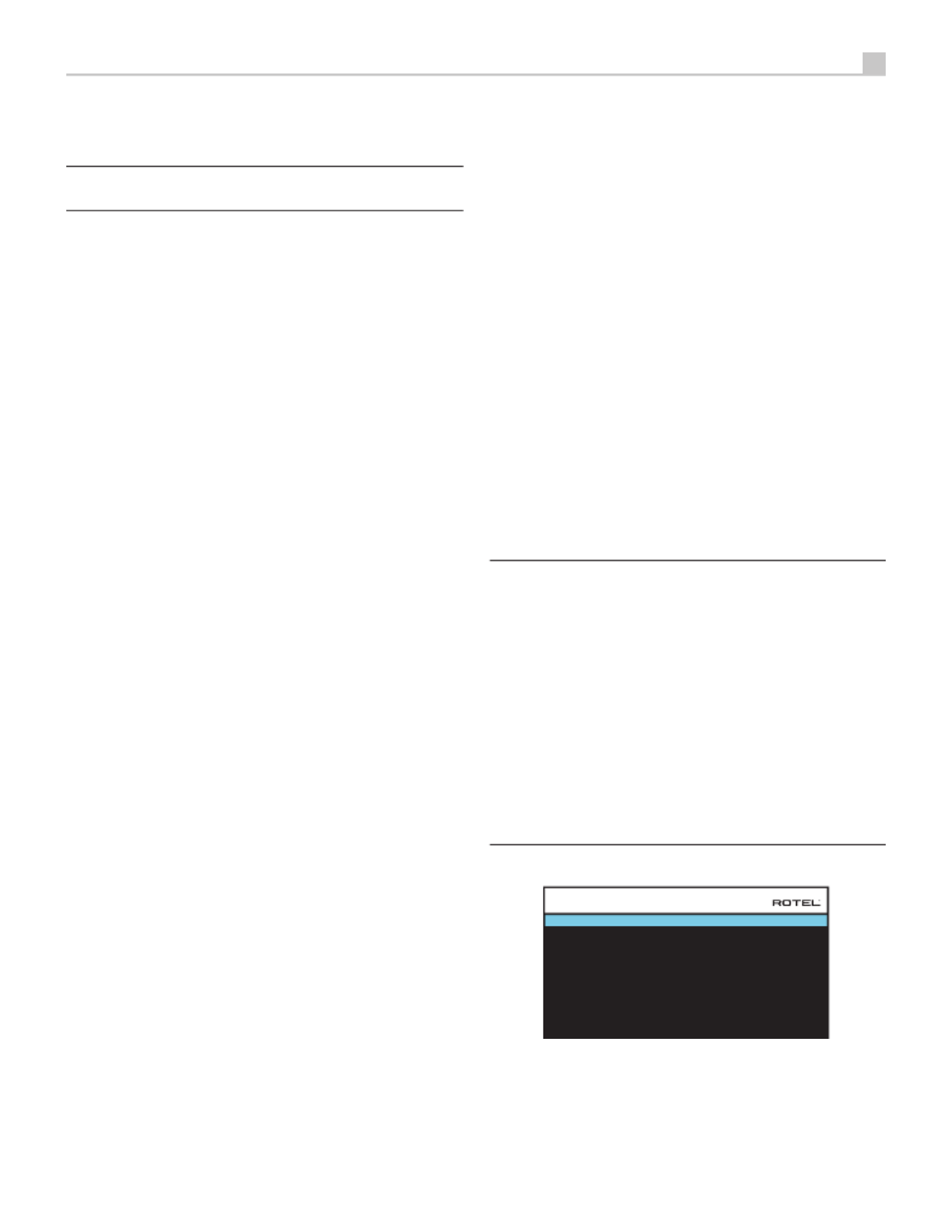
45
Français
désirée les sorties haut-parleurs et préamplicateur RCA signaux audio de
sortie des connexions sont afchées pour jusqu’à 12 canaux.
REMARQUE : Certaines sorties ne sont disponibles que via les sorties
RCA préamplificateur et nécessitent un amplificateur externe.
Conguration des Enceintes et de la partie Audio
Cette étape de la procédure de conguration traite les points concernant
la reproduction sonore, tels que le nombre d’enceintes, la gestion du grave
(ou « bass management) dont le ltrage du caisson de graves, l’égalisation
du niveau de sortie pour tous les canaux, les réglages du temps de retard
et enn l’égalisation paramétrique.
Comprendre la conguration des enceintes
Les installations Home Cinéma diffèrent suivant le nombre d’enceintes et
les capacités de reproduction du grave de ces enceintes. Votre processeur
dispose des modes surround adaptés aux installations équipées d’un nombre
varié d’enceintes et d’une fonction de gestion du grave qui envoie le signal
basse fréquence à (aux) l’enceinte(s) la (les) plus capable(s) de le traiter –
caisson de graves ou enceintes de grande taille. Pour un résultat optimal,
vous devez indiquer à l’appareil le nombre d’enceintes qui équipent votre
installation et comment le grave doit être réparti parmi celles-ci.
Les instructions concernant la conguration de votre système données ci-
dessous font référence à des petites (SMALL) ou grandes (LARGE) enceintes,
ceci davantage pour indiquer la qualité sonore des enceintes dans les basses
fréquences plutôt que leur taille physique. Une grande enceinte capable
de reproduire toute la bande passante pourra être considérée comme «
LARGE ». Par contre, une petite enceinte de bibliothèque limitée dans le
grave sera considérée comme « SMALL ». Ainsi, utilisez le réglage LARGE
pour les enceintes dont vous souhaitez une reproduction profonde du grave.
Utilisez SMALL pour les enceintes qui gagnent à voir une partie du grave
qui leur est normalement destiné, redirigé vers des enceintes possédant de
meilleures aptitudes dans ce domaine. Ce système de gestion du grave
(bass management) empêche le grave de parvenir aux enceintes SMALL
et redirige le signal aux enceintes LARGE et/ou au caisson de graves. Il
peut être utile de considérer comme LARGE des grandes enceintes colonnes
«pleine bande passante » et comme SMALL des petites enceintes limitées
au registre médium-aigus comme des enceintes bibliothèques.
• Cinq grandes enceintes LARGE et un caisson de graves (subwoofer). Ce
système ne nécessite aucune re-direction du grave. Les cinq enceintes
reproduisent normalement toute la bande passante de leur canal
respectif. Le caisson de graves reproduit le canal de grave « normal ».
Notez que la reproduction du grave « normal » demande parallèlement
de meilleures capacités aux autres enceintes et amplicateurs chargés
de les alimenter.
• Des grandes enceintes LARGE à l’avant, au centre, et à l’arrière
Surround, mais pas de caisson de graves. Dans ce cas, les cinq
enceintes continuent à reproduire toute la bande passante de chacun
de leurs canaux respectifs.
• Des petites enceintes SMALL et un caisson de graves. La reproduction du
grave de tous les canaux est alors redirigée vers le caisson de graves.
C’est donc le caisson de graves qui reproduit TOUT le grave du signal
sonore. Les autres enceintes bénécient ainsi d’un fonctionnement
facilité, leur permettant de se « consacrer » à la dynamique et à la
spatialisation de la reproduction sonore totale. On se retrouve ici avec
la majeure partie des avantages de la bi-amplication : le grave n’est
reproduit que par l’enceinte (le caisson de graves ou subwoofer) la mieux
adaptée pour ce faire, tandis que les autres enceintes peuvent fournir
un niveau sonore plus élevé avec moins de risques de distorsion, et une
demande en puissance des amplicateurs moins forte. C’est désormais
la conguration la plus répandue dans les installations Home Cinema.
On peut parfaitement l’envisager même si les enceintes, de grande
taille, semblent parfaitement capables de reproduire correctement
les fréquences basses. Elle est en effet très avantageuse avec des
amplicateurs de puissance modérée.
• Des grandes enceintes latérales avant LARGE, mais de petites enceintes
SMALL en canal central avant et canaux arrière Surround, et un caisson
de graves. La reproduction normale du grave des canaux central
avant et arrière Surround est alors redirigée vers les grandes enceintes
latérales avant et le caisson de graves. Les enceintes latérales avant
reproduisent donc le grave de leurs propres canaux, plus le grave des
enceintes centrales avant et arrière Surround. Le caisson de graves
reproduit une partie du grave des enceintes centrale avant et arrière
Surround. Ce sera le choix optimal si l’on possède d’excellentes enceintes
avant gauche et droite, alimentées par un amplicateur puissant et
d’excellente qualité. L’inconvénient possible avec les congurations
mixtes mélangeant les enceintes SMALL et LARGE est que la réponse
dans le grave n’est pas homogène d’un canal à l’autre comme elle
l’est avec une conguration entièrement en SMALL.
REMARQUE : Une dernière configuration concerne les packs
composés d’enceintes dites satellites et d’un caisson de graves. Dans
ce cas, suivez les instructions du constructeur du pack en question. On
branchera alors généralement les entrées haut niveau du caisson de
graves directement sur les sorties des enceintes frontales de l’appareil,
puis on branchera ensuite les enceintes satellites directement sur leurs
prises dédiées du caisson de graves, en utilisant le filtre intégré dans
celui-ci. Dans ce cas, les enceintes devront être configurées en mode
LARGE et le caisson de graves annoncé comme absent (OFF) dans tous
les modes Surround. Aucune information sonore n’est alors perdue,
puisque toute l’information des fréquences graves est redirigée vers la
sortie des enceintes principales. Bien que cette configuration garantisse
une utilisation optimale des enceintes satellite en utilisant le propre
système de filtrage du pack satellites-caisson de graves, on perd en
souplesse au niveau de la calibration du système. Ce n’est pas une
configuration que nous préconisons.
Conguration des enceintes
FRONT : Large
CENTER : Large
SURROUND : Large
SUBWOOFER : Yes
CEILING REAR : Large
ADVANCED SETUP
BACK
CENTER BACK : 2 Large
CEILING FRONT : Large
SPEAKER CONFIGURATION
Le menu de conguration des enceintes (SPEAKER CONFIGURATION) est
utilisé pour adapter le fonctionnement du RAP-1580 à vos enceintes et
pour déterminer la conguration du système de gestion du grave comme
décrit précédemment. Le menu est accessible depuis le menu principal
(MAIN MENU).
Les options suivantes sont disponibles :

47
Français
REMARQUE : La position OFF (disponible uniquement pour le caisson
de graves) permet d’envoyer un signal intégral à votre caisson de
graves de sorte que vous puissiez utiliser son filtre passe-bas interne.
REMARQUE : Quand une enceinte est réglée sur GRANDE (LARGE)
dans le menu SPEAKER SETUP ou dans ce menu), le réglage du filtrage
n’est pas disponible puisque, par définition, une « grande » enceinte est
censée restituer toute la bande passante sans re-direction du grave vers
le caisson de graves et sans filtrage. Enfin, le réglage de la fréquence
de coupure n’est pas disponible avec l’entrée MULTI INPUT.
DOLBY (Default/ Large/Small/None (Par défaut/ grande/petite/aucune)):
Règle l’enceinte (afchée sur la ligne « enceinte » ou speaker en anglais) sur
GRANDE (LARGE), PETITE (SMALL) ou AUCUNE (NONE), court-circuitant
ainsi le réglage du menu Conguration des enceintes (Speaker Setup). Si
vous voulez utiliser le réglage de taille d’enceinte spécié dans le menu
SPEAKER SETUP, choisissez « Default ». L’option « None » n’est pas proposée
pour les enceintes frontales (FRONT).
DTS (Default/ Large/Small/None) : Mêmes fonctions que celles décrites
ci-dessus pour le Dolby, à ceci près que ces réglages ne sont actifs
UNIQUEMENT pour le DTS.
STEREO (Default/ Large/Small/None) : Même fonction que celle décrit ci-dessus
pour le Dolby, à ceci près que ces réglages ne sont actifs UNIQUEMENT
avec le mode surround STEREO.
Concernant le caisson de graves, les options listées ci-dessus pour DOLBY,
DTS et STEREO deviennent « Yes/No/Default », et devrai être positionné
sur « Yes » si les enceintes avant sont réglées sur « Small ».
REMARQUE : Quand les enceintes avant sont configurées pour les
réglages par défaut du menu Configuration Avancée des Enceintes,
les réglages spécifiques « Grande/Petite/Aucune » de DOLBY, DTS
ou STEREO ne sont pas proposées pour les autres enceintes. Ces
enceintes utiliseront le réglage déterminé dans le menu Configuration
des Enceintes (SPEAKER SETUP).
Conguration du caisson de graves
DOLBY : 0dB
DTS : 0dB
STEREO : 0dB
MULTI LPCM : 0dB
MULTI INPUT : 0dB
BACK
SUBWOOFER SETUP
Ces cinq lignes vous permettent de court-circuiter le réglage de référence du
niveau du caisson de graves, déterminé dans le menu Réglages du niveau des
enceintes (Speaker Level Setup, voir plus bas) pour chaque mode surround.
DOLBY :
DTS :
STEREO :
MULTI LPCM :
MULTI INPUT :
Utilisez les touches Up/Down ( Haut/Bas) pour mettre en surbrillance le
mode spécié, puis les touches LEFT/RIGHT (gauche/droite) pour ajuster
le niveau du caisson du mode affiché. Vous disposez d’une gamme
d’ajustements de – 9 dB à +9 dB et MAX (+ 10 dB). Un réglage sur 0 dB
signie que le mode surround spécié reprendra le niveau de référence du
caisson de graves. Tout autre réglage est une variation par rapport à ce
réglage de référence. Par exemple, un ajustement de – 2dB signie que le
niveau du caisson de graves sera 2 dB plus bas que le niveau de référence
quand ce mode surround sera sélectionné. Utilisez ces réglages du niveau
du caisson de graves pour ajuster le niveau de sortie relatif aux différents
modes surround. Changer le niveau de référence du caisson augmentera
ou diminuera le niveau pour tous les modes surround.
Nous vous recommandons de commencer avec les réglages positionnés sur
0 dB pour tous les modes surround pendant la calibration de l’installation à
l’aide du générateur de signal de test, et pendant une période de familiarisation
après. En écoutant différents programmes, vous noterez que certains modes
surround produisent souvent trop ou trop peu de grave à partir du caisson
de graves. Si tel est le cas, utilisez ces menus de réglage pour personnaliser
chaque mode surround. En général, si le niveau de référence du caisson
est correctement réglé (c’est-à-dire pas trop fort), les réglages individuels
pour chaque surround ne sont pas nécessaires.
Pour revenir au menu principal MAIN, appuyez sur la touche SELECT.
Appuyez sur la touche MENU/OSD de la télécommande pour supprimer
l’afchage et revenir à un fonctionnement normal.
Réglage des niveaux des enceintes
FRONT LEFT : 0dB
CENTER : 0dB
FRONT RIGHT : 0dB
SURROUND RIGHT : 0dB
CENTER BACK RIGHT : 0dB
CENTER BACK LEFT : 0dB
SURROUND LEFT : 0dB
SUBWOOFER : 0dB
BACK
CEILING FRONT RIGHT : 0dB
CEILING REAR RIGHT : 0dB
CEILING REAR LEFT : 0dB
CEILING FRONT LEFT : 0dB
SPEAKER LEVEL SETUP
REMARQUE : Si vous avez configuré votre installation de manière
à utiliser deux enceintes centrales arrière, il y aura une ligne
supplémentaire dans le menu, offrant la possibilité d’ajuster
indépendamment les niveaux dess enceintes centrales arrières CENTER
BACK LEFT et CENTER BACK RIGHT.
Ce menu utilise des signaux audio de test sous forme de bruit rose permet
d’équilibrer les niveaux acoustiques de l’ensemble des enceintes (avant
gauche, centrale, avant droite, surround droite, centrale arrière droite,
plafond avant droite, plafond arrière droite, surround gauche, plafond
avant gauche, plafond arrière gauche, centrale arrière gauche, et caisson
de graves) an d’assurer une reproduction sonore surround correcte. Régler
les niveaux en utilisant la procédure de test permet un ajustement précis
et constitue une étape cruciale dans la calibration de votre installation.
Pour accéder à ce menu et exécuter le test de calibration, vous pouvez vous
situer dans n’importe quel mode surround excepté BYPASS et sur n’importe
quelle entrée exceptée MULTI INPUT. Entrez dans le système de menus OSD
et sélectionnez le paramètre SPEAKER LEVEL SETUP depuis le menu principal
pour accéder à cet écran.
Produktspezifikationen
| Marke: | Rotel |
| Kategorie: | Empfänger |
| Modell: | RAP-1580 |
Brauchst du Hilfe?
Wenn Sie Hilfe mit Rotel RAP-1580 benötigen, stellen Sie unten eine Frage und andere Benutzer werden Ihnen antworten
Bedienungsanleitung Empfänger Rotel

16 Oktober 2024
27 September 2024
5 September 2024
5 September 2024
4 September 2024
4 September 2024
31 August 2024
28 August 2024
25 August 2024
23 August 2024
Bedienungsanleitung Empfänger
- Empfänger Asus
- Empfänger Belkin
- Empfänger Exibel
- Empfänger Hama
- Empfänger Audio-Technica
- Empfänger LogiLink
- Empfänger Logitech
- Empfänger Manhattan
- Empfänger Medion
- Empfänger Nedis
- Empfänger Philips
- Empfänger Sandberg
- Empfänger Sony
- Empfänger Zalman
- Empfänger Panasonic
- Empfänger Roland
- Empfänger MX Onda
- Empfänger Bosch
- Empfänger Vox
- Empfänger TechniSat
- Empfänger Yamaha
- Empfänger Velleman
- Empfänger Neumann
- Empfänger CSL
- Empfänger Devolo
- Empfänger Schwaiger
- Empfänger Alecto
- Empfänger Conrad
- Empfänger Denver
- Empfänger EMOS
- Empfänger Gira
- Empfänger König
- Empfänger MarQuant
- Empfänger Renkforce
- Empfänger Bush
- Empfänger Thomson
- Empfänger Trevi
- Empfänger Blaupunkt
- Empfänger Grundig
- Empfänger Kenwood
- Empfänger Sharp
- Empfänger Hilti
- Empfänger Pyle
- Empfänger Golden Age Project
- Empfänger Salora
- Empfänger Telestar
- Empfänger Aiwa
- Empfänger AKG
- Empfänger Auna
- Empfänger Bang And Olufsen
- Empfänger Bose
- Empfänger Bowers And Wilkins
- Empfänger Caliber
- Empfänger Maxview
- Empfänger Denon
- Empfänger Pioneer
- Empfänger Geemarc
- Empfänger Jabra
- Empfänger JBL
- Empfänger JVC
- Empfänger Klipsch
- Empfänger Krüger And Matz
- Empfänger Meliconi
- Empfänger Motorola
- Empfänger Nokia
- Empfänger Onkyo
- Empfänger Optoma
- Empfänger Sennheiser
- Empfänger Shure
- Empfänger Technics
- Empfänger Teufel
- Empfänger Vivanco
- Empfänger Hifonics
- Empfänger Megasat
- Empfänger Smartwares
- Empfänger Akai
- Empfänger Alden
- Empfänger Dual
- Empfänger Ferguson
- Empfänger GoGEN
- Empfänger Hyundai
- Empfänger Orava
- Empfänger Strong
- Empfänger Tesla
- Empfänger Imperial
- Empfänger Tascam
- Empfänger Zoom
- Empfänger Garmin
- Empfänger Nexa
- Empfänger Sencor
- Empfänger Goobay
- Empfänger Lindy
- Empfänger Astro
- Empfänger Plantronics
- Empfänger Fenton
- Empfänger TOA
- Empfänger Musway
- Empfänger Tripp Lite
- Empfänger Audio Pro
- Empfänger Cabasse
- Empfänger Canton
- Empfänger Dali
- Empfänger Harman Kardon
- Empfänger Inateck
- Empfänger Magnat
- Empfänger Marmitek
- Empfänger Marshall
- Empfänger Naim
- Empfänger Power Dynamics
- Empfänger Samson
- Empfänger Scosche
- Empfänger Skytec
- Empfänger Tangent
- Empfänger Vonyx
- Empfänger Peavey
- Empfänger Marshall Electronics
- Empfänger Sagem
- Empfänger Simrad
- Empfänger AVM
- Empfänger Xoro
- Empfänger Karma
- Empfänger Atlas
- Empfänger Reely
- Empfänger Edision
- Empfänger GigaBlue
- Empfänger Humax
- Empfänger Kathrein
- Empfänger Metronic
- Empfänger Smart
- Empfänger Topfield
- Empfänger Xtrend
- Empfänger Zehnder
- Empfänger Icom
- Empfänger Brondi
- Empfänger Alpine
- Empfänger Rupert Neve Designs
- Empfänger NAD
- Empfänger Fender
- Empfänger Renegade
- Empfänger Ebode
- Empfänger LTC
- Empfänger Vincent
- Empfänger Vision
- Empfänger Hager
- Empfänger Behringer
- Empfänger Mackie
- Empfänger Omnitronic
- Empfänger Thomann
- Empfänger MB Quart
- Empfänger Marantz
- Empfänger Monoprice
- Empfänger Arcam
- Empfänger Cambridge
- Empfänger Crown
- Empfänger Dynacord
- Empfänger Ecler
- Empfänger Luxman
- Empfänger Monacor
- Empfänger Rockford Fosgate
- Empfänger TEAC
- Empfänger Thorens
- Empfänger Crunch
- Empfänger Chamberlain
- Empfänger JUNG
- Empfänger Aplic
- Empfänger InLine
- Empfänger Sangean
- Empfänger Classé
- Empfänger Optex
- Empfänger Revox
- Empfänger Sherwood
- Empfänger Jamo
- Empfänger AXTON
- Empfänger Clarion
- Empfänger Mac Audio
- Empfänger Kogan
- Empfänger Genie
- Empfänger Humantechnik
- Empfänger T-Mobile
- Empfänger Skytronic
- Empfänger Yaesu
- Empfänger Audizio
- Empfänger ESX
- Empfänger Reloop
- Empfänger HQ
- Empfänger Pinnacle
- Empfänger Block
- Empfänger Rega
- Empfänger SYNQ
- Empfänger Amazon
- Empfänger Insignia
- Empfänger August
- Empfänger Audison
- Empfänger DataVideo
- Empfänger RCF
- Empfänger Electro-Voice
- Empfänger Cyrus
- Empfänger Scansonic
- Empfänger Sogo
- Empfänger Cisco
- Empfänger Delta Dore
- Empfänger Salus
- Empfänger Sonos
- Empfänger Yorkville
- Empfänger MIPRO
- Empfänger Elektrobock
- Empfänger FiiO
- Empfänger Boss
- Empfänger IFM
- Empfänger Intertechno
- Empfänger American Audio
- Empfänger Anthem
- Empfänger Roksan
- Empfänger Engel Axil
- Empfänger Alto
- Empfänger Kopul
- Empfänger Chord
- Empfänger Saramonic
- Empfänger Kramer
- Empfänger Hertz
- Empfänger Pro-Ject
- Empfänger Aeon Labs
- Empfänger Vaddio
- Empfänger Galaxy Audio
- Empfänger HQ Power
- Empfänger Ibiza Sound
- Empfänger Kicker
- Empfänger Warm Audio
- Empfänger Polk
- Empfänger Line 6
- Empfänger Bogen
- Empfänger DBX
- Empfänger Radial Engineering
- Empfänger McIntosh
- Empfänger Sonance
- Empfänger Jensen
- Empfänger ELAC
- Empfänger Fostex
- Empfänger JL Audio
- Empfänger Pyle Pro
- Empfänger PreSonus
- Empfänger Qtx
- Empfänger Hartke
- Empfänger ART
- Empfänger Deaf Bonce
- Empfänger Fredenstein
- Empfänger LD Systems
- Empfänger RDL
- Empfänger Audiolab
- Empfänger Oculus VR
- Empfänger Summit Audio
- Empfänger Homematic IP
- Empfänger Black Lion Audio
- Empfänger Dreambox
- Empfänger Bluesound
- Empfänger Solid State Logic
- Empfänger RME
- Empfänger GlobalSat
- Empfänger Chandler
- Empfänger DAP
- Empfänger DAP Audio
- Empfänger Definitive Technology
- Empfänger Denson
- Empfänger Devialet
- Empfänger DIO
- Empfänger DLS
- Empfänger Focal
- Empfänger Focusrite
- Empfänger Formuler
- Empfänger Fusion
- Empfänger Graupner
- Empfänger Ground Zero
- Empfänger Helix
- Empfänger Hirschmann
- Empfänger Homecast
- Empfänger Infinity
- Empfänger Iriver
- Empfänger JB Systems
- Empfänger Koda
- Empfänger Lanzar
- Empfänger Legamaster
- Empfänger Medeli
- Empfänger Mercury
- Empfänger Monitor Audio
- Empfänger Mtx Audio
- Empfänger Mvision
- Empfänger Naxa
- Empfänger Octagon
- Empfänger Phoenix Gold
- Empfänger Raymarine
- Empfänger REL Acoustics
- Empfänger Selfsat
- Empfänger Soundstream
- Empfänger Stagg
- Empfänger Steren
- Empfänger Stinger
- Empfänger Sunstech
- Empfänger Terratec
- Empfänger ACV
- Empfänger AMX
- Empfänger Triax
- Empfänger Tronics
- Empfänger TV STAR
- Empfänger Universal Remote Control
- Empfänger Velodyne
- Empfänger Vivotek
- Empfänger Wharfedale
- Empfänger Winegard
- Empfänger Xsarius
- Empfänger Zgemma
- Empfänger Universal Audio
- Empfänger Phonic
- Empfänger Epcom
- Empfänger Adastra
- Empfänger Siig
- Empfänger Amiko
- Empfänger Cloud
- Empfänger Mooer
- Empfänger AudioControl
- Empfänger MXL
- Empfänger TV One
- Empfänger NAV-TV
- Empfänger StarTech.com
- Empfänger APart
- Empfänger Blackstar
- Empfänger HEOS
- Empfänger Smart-AVI
- Empfänger QSC
- Empfänger RetroSound
- Empfänger Dahua Technology
- Empfänger Proel
- Empfänger Niles
- Empfänger Panduit
- Empfänger Martin Logan
- Empfänger Metra
- Empfänger Kanto
- Empfänger PAC
- Empfänger Sound Devices
- Empfänger Speco Technologies
- Empfänger IFi Audio
- Empfänger Gefen
- Empfänger Polsen
- Empfänger Bugera
- Empfänger Russound
- Empfänger Vocopro
- Empfänger SRS
- Empfänger Comica
- Empfänger Astell&Kern
- Empfänger IMG Stage Line
- Empfänger Inovonics
- Empfänger Mosconi
- Empfänger Atlas Sound
- Empfänger FBT
- Empfänger DB Technologies
- Empfänger CYP
- Empfänger Amplicom
- Empfänger Micromega
- Empfänger Palmer
- Empfänger Jolida
- Empfänger Ampeg
- Empfänger Avalon
- Empfänger BOYA
- Empfänger Audient
- Empfänger Bang Olufsen
- Empfänger Lectrosonics
- Empfänger ATen
- Empfänger Eventide
- Empfänger Axing
- Empfänger Laney
- Empfänger Morel
- Empfänger SVS
- Empfänger KanexPro
- Empfänger Citronic
- Empfänger Crest Audio
- Empfänger Lab Gruppen
- Empfänger SPL
- Empfänger Parasound
- Empfänger Apantac
- Empfänger Brigmton
- Empfänger Axis
- Empfänger MEE Audio
- Empfänger Wet Sounds
- Empfänger Edisio
- Empfänger Pyramid
- Empfänger Stewart
- Empfänger Black Hydra
- Empfänger Linn
- Empfänger Roswell
- Empfänger Music Hall
- Empfänger Audac
- Empfänger OSD Audio
- Empfänger Match
- Empfänger Audioengine
- Empfänger Neets
- Empfänger EA
- Empfänger BZBGear
- Empfänger Crestron
- Empfänger PSSO
- Empfänger HiFi ROSE
- Empfänger Accell
- Empfänger Ibanez
- Empfänger Antelope Audio
- Empfänger Pharos
- Empfänger Kemo
- Empfänger Audix
- Empfänger Viscount
- Empfänger GOgroove
- Empfänger Avantree
- Empfänger PSB
- Empfänger Phoenix Audio
- Empfänger Extron
- Empfänger Atlona
- Empfänger Comtek
- Empfänger LYYT
- Empfänger JTS
- Empfänger Redline
- Empfänger Valueline
- Empfänger Grace Design
- Empfänger Ashdown Engineering
- Empfänger Ram Audio
- Empfänger Esoteric
- Empfänger Xantech
- Empfänger Wavtech
- Empfänger Krell
- Empfänger Artsound
- Empfänger Rolls
- Empfänger Sonifex
- Empfänger Advance Acoustic
- Empfänger Kali Audio
- Empfänger Leviton
- Empfänger Revel
- Empfänger WyreStorm
- Empfänger Wireless Solution
- Empfänger Manley
- Empfänger Klark Teknik
- Empfänger Lindell Audio
- Empfänger AVMATRIX
- Empfänger Alfatron
- Empfänger Acme United
- Empfänger Mark Levinson
- Empfänger CAD Audio
- Empfänger Dynavox
- Empfänger Key Digital
- Empfänger AER
- Empfänger Cerwin-Vega
- Empfänger Sound Ordnance
- Empfänger Majestic
- Empfänger Ocean Matrix
- Empfänger Markbass
- Empfänger AmpliVox
- Empfänger LEA
- Empfänger Memphis Audio
- Empfänger FiveO
- Empfänger Televes
- Empfänger Aquatic AV
- Empfänger DirecTV
- Empfänger Ashly
- Empfänger Fishman
- Empfänger AVPro Edge
- Empfänger Integra
- Empfänger Matrox
- Empfänger Blustream
- Empfänger CyberData Systems
- Empfänger Williams Sound
- Empfänger Sunfire
- Empfänger SoundTube
- Empfänger JETI
- Empfänger SureCall
- Empfänger Vivolink
- Empfänger WesAudio
- Empfänger ANKARO
- Empfänger NUVO
- Empfänger Audiofrog
- Empfänger Canyon
- Empfänger AMS Neve
- Empfänger Trace Elliot
- Empfänger The T.amp
- Empfänger Knoll
- Empfänger MuxLab
- Empfänger Hegel
- Empfänger Triangle
- Empfänger Whirlwind
- Empfänger Camille Bauer
- Empfänger Hughes & Kettner
- Empfänger Rocketfish
- Empfänger Dimavery
- Empfänger Palsonic
- Empfänger Musical Fidelity
- Empfänger Rexing
- Empfänger A-NeuVideo
- Empfänger Crest
- Empfänger Cranborne Audio
- Empfänger Seco-Larm
- Empfänger Primare
- Empfänger C2G
- Empfänger Fosi Audio
- Empfänger S.M.S.L
- Empfänger Aurel
- Empfänger Advance
- Empfänger AEA
- Empfänger Datapath
- Empfänger TechLogix Networx
- Empfänger PTN-electronics
- Empfänger CE Labs
- Empfänger Gold Note
- Empfänger Planet Audio
- Empfänger Lotronic
- Empfänger Audiotec Fischer
- Empfänger Sinus Live
- Empfänger Shinybow
- Empfänger Shanling
- Empfänger Fontastic
- Empfänger BC Acoustique
- Empfänger NuPrime
- Empfänger Taga Harmony
- Empfänger Creek
- Empfänger BMB
- Empfänger Valcom
- Empfänger Intelix
- Empfänger Madison
- Empfänger Topp Pro
- Empfänger Whistler
- Empfänger Powersoft
- Empfänger LinksPoint
- Empfänger Modelcraft
- Empfänger Simaudio
- Empfänger TIC
- Empfänger Mobile Crossing
- Empfänger FSR
- Empfänger Edwards Signaling
- Empfänger Lyngdorf
- Empfänger AudioSource
- Empfänger Leema
- Empfänger Quad
- Empfänger IOTAVX
- Empfänger Inter-M
- Empfänger Soundtrack
- Empfänger Canor
- Empfänger Unison Research
- Empfänger Clare Controls
- Empfänger Loxjie
- Empfänger Cayin
- Empfänger Technical Pro
- Empfänger VMV
- Empfänger Bellari
- Empfänger Comprehensive
- Empfänger PureLink
- Empfänger FoneStar
- Empfänger Glemm
Neueste Bedienungsanleitung für -Kategorien-
2 Dezember 2024
1 Dezember 2024
30 November 2024
30 November 2024
30 November 2024
30 November 2024
30 November 2024
30 November 2024
30 November 2024
29 November 2024