Panasonic WV-SPW311A Bedienungsanleitung
Panasonic
Überwachungskamera
WV-SPW311A
Lesen Sie kostenlos die 📖 deutsche Bedienungsanleitung für Panasonic WV-SPW311A (222 Seiten) in der Kategorie Überwachungskamera. Dieser Bedienungsanleitung war für 7 Personen hilfreich und wurde von 2 Benutzern mit durchschnittlich 4.5 Sternen bewertet
Seite 1/222
Operating Instructions
Network Camera
Model No. WV-SFV311A/WV-SFV310A/
WV-SFR311A/WV-SFR310A/
WV-SFN311A/WV-SFN310A/
WV-SPN531A/WV-SPN311A/
WV-SPN310A/WV-SPW531AL/
WV-SPW311AL/WV-SPW532L/
WV-SPW312L
WV-SFV311A
WV-SFV311 A WV-SFN31 1A
WV-SFN311A
WV-SPN531A
WV-S PN531A
Before attempting to connect or operate this product, please read these instructions
carefully and save this manual for future use.
The model number is abbreviated in some descriptions in this manual.

Preface
About the user manuals
There are 3 sets of operating instructions as follows.
•Operating Instructions (this document): Explains how to perform the settings and how to operate this
camera.
•Important Information: Provides information about the cautions required for safely using and installing this
camera.
•Installation Guide: Explains how to install and connect devices.
About notations
The following notations are used when describing the functions limited for specified models.
The functions without the notations are supported by all models.
Notation Available model Notation Available model
SFx311
WV-SFV311A, WV-SFR311A,
WV-SFN311A
SFx310
WV-SFV310A, WV-SFR310A,
WV-SFN310A
SFV311
WV-SFV311A, WV-SFV310A,
WV-SFR311A, WV-SFR310A,
WV-SFN311A, WV-SFN310A,
WV-SPN311A, WV-SPN310A,
WV-SPW311AL, WV-SPW312L
SFV310
WV-SFV310A
SFR310
WV-SFR310A
SFN310
WV-SFN310A
SPN311
WV-SPN311A
SPN310
WV-SPN310A
SPW311L
WV-SPW311AL
SPW312L
WV-SPW312L
SPN531
WV-SPN531A
SPW531L
WV-SPW531AL
SPW532L
WV-SPW532L
Trademarks and registered trademarks
•Microsoft, Windows, Windows Vista, Windows Media, Internet Explorer, and ActiveX are either registered
trademarks or trademarks of Microsoft Corporation in the United States and/or other countries.
•Microsoft product screen shot(s) reprinted with permission from Microsoft Corporation.
•iPad, iPhone, iPod touch, and QuickTime are trademarks of Apple Inc., registered in the U.S. and other
countries.
•Android is a trademark of Google Inc.
•Firefox is a registered trademark of the Mozilla Foundation.
•SDXC Logo is a trademark of SD-3C, LLC.
•All other trademarks identified herein are the property of their respective owners.
2 Operating Instructions
Preface
Abbreviations
The following abbreviations are used in these operating instructions.
Microsoft® Windows® 8.1 is described as Windows 8.1.
Microsoft® Windows® 8 is described as Windows 8.
Microsoft® Windows® 7 is described as Windows 7.
Microsoft® Windows Vista® is described as Windows Vista.
Windows® Internet Explorer® 11, Windows® Internet Explorer® 10, Windows® Internet Explorer® 9, Windows®
Internet Explorer® 8 and Windows® Internet Explorer® 7 are described as Internet Explorer.
SDXC/SDHC/SD memory card is described as SD card or SD memory card.
Universal Plug and Play is described as UPnP™.
Viewer software
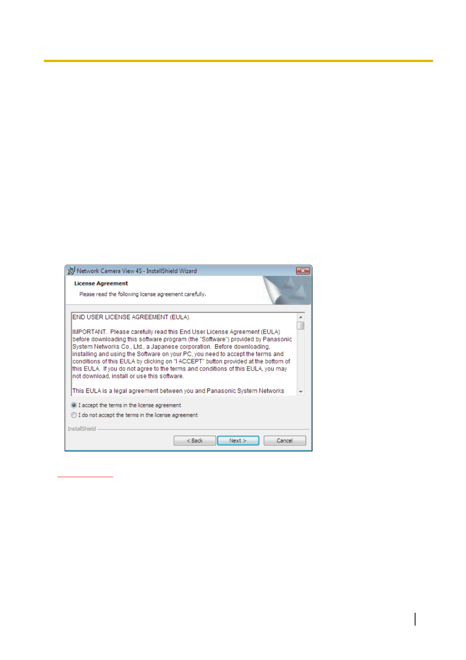
It is necessary to install the viewer software “Network Camera View 4S” (ActiveX®) to display images on a PC.
This software can be installed directly from the camera or by selecting the [Install] button next to [Viewer
Software] on the menu of the CD-ROM provided, and then following the on-screen instructions.
IMPORTANT
•The default setting of “Automatic installation” is “On”. Follow the instructions on page 219 when the
message is displayed on the information bar of the browser.
•When the “Live” page is displayed for the first time, the install wizard of the ActiveX control required to
display images from the camera will be displayed. Follow the instructions of the wizard.
•When the install wizard is displayed again even after completing the installation of the ActiveX, restart
the PC.
•The viewer software used on each PC should be licensed individually. The number of installations of
the viewer software from the camera can be checked on the [Upgrade] tab of the “Maintenance” page
( page 191). Refer to your dealer for the software licensing.®
Operating Instructions 3
Preface

Table of Contents
1 Monitor images on a PC ..........................................................................8
1.1 Monitor images from a single camera .............................................................................8
1.2 About the “Live” page .. 10..................................................................................................
1.3 Monitor cropping images .. 14.............................................................................................
1.4 Monitor images from multiple cameras .. 17......................................................................
2 Monitor images on a cellular phone/mobile terminal .. 18.......................
2.1 Monitor images on a cellular phone .. 18............................................................................
2.2 Monitor images on a mobile terminal .. 20..........................................................................
3 Record images on the SD memory card manually .. 25...........................
4 Action at an alarm occurrence .. 27............................................................
4.1 Alarm type .. 27......................................................................................................................
4.2 Action at an alarm occurrence .. 27.....................................................................................
5 Transmit images onto an FTP server .. 29.................................................
5.1 Transmit an alarm image at an alarm occurrence (Alarm image
transmission) .. 29.................................................................................................................
5.2 Transmit images at a designated interval or period (FTP periodic image
transmission) .. 29.................................................................................................................
5.3 Save images on the SD memory card when images fail to transmit using the FTP
periodic image transmission function .. 30........................................................................
6 Display the log list .................................................................................31
7 Playback of images on the SD memory card .. 35....................................
7.1 Playback “JPEG(1)”/“JPEG(2)”/“JPEG(3)” images saved to the SD memory
card .. 35.................................................................................................................................
7.2 Playback “H.264(1)”/“H.264(2)”/“H.264(3)”/“H.264(4)” images saved to the SD
memory card .. 38..................................................................................................................
8 About the network security .. 41.................................................................
8.1 Equipped security functions .. 41........................................................................................
9 Display the setup menu from a PC .. 42.....................................................
9.1 How to display the setup menu .. 42...................................................................................
9.2 How to operate the setup menu .. 44...................................................................................
9.3 About the setup menu window .. 46....................................................................................
10 Configure the basic settings of the camera [Basic] .. 48.........................
10.1 Configure the basic settings [Basic] .. 48...........................................................................
10.2 Configure the Internet settings [Internet] .. 53...................................................................
10.3 Configure the settings relating to the SD memory card [SD memory card] .. 55............
10.4 Configure the settings relating to alteration detection [Alteration detection] ..........63
10.5 How to configure alteration detection settings .. 64..........................................................
10.5.1 Generation of the CRT key (encryption key) .. 65................................................................
10.5.2 Generation of the self-signed certificate (security certificate) .. 66.......................................
10.5.3 Generation of CSR (Certificate Signing Request) .. 68........................................................
10.5.4 Installation of the certificate issued by CA .. 70....................................................................
10.5.5 Configuration of alteration detection .. 71.............................................................................
4 Operating Instructions
Table of Contents

10.6 Access copy images saved on the SD memory card onto the PC [SD memory card
images] .. 72...........................................................................................................................
10.7 Configure the directory of the PC that images will be downloaded to [Log] ............74
11 Configure the settings relating to images and audio [Image/
Audio] ......................................................................................................76
11.1 Configure the settings relating to the image capture mode [JPEG/H.264] .. 76..............
11.2 Configure the settings relating to JPEG images [JPEG/H.264] .. 77................................
11.3 Configure the settings relating to H.264 images [JPEG/H.264] .. 79................................
11.4 Configure the settings relating to image adjust, focus, back focus, extra optical zoom,
privacy zone, VIQS, and lens distortion compensation [Image quality] .. 86..................
11.4.1 Configure the settings relating to image quality (“Image adjust” setup menu) .. 87.............
11.4.2 Set mask areas .. 96............................................................................................................
11.5 Configure the focus setting (“Focus” setup menu)
SFx311
SFx310
SPW311L
SPW312L
SPW531L
SPW532L
.. 99.............................................................................................................
11.6 Back focus setting (“Back focus” setup menu)
SPN311
SPN531
.. 100...........................
11.7 Adjust the angular field of view using the extra optical zoom function .. 101................
11.8 Configure the settings relating to the privacy zone (“Privacy zone” setup
menu) .............................................................................................................................103
11.9 Configure the VIQS setting .. 105........................................................................................
11.10 Configure the VIQS area .. 107.............................................................................................
11.11 Configure the settings relating to lens distortion compensation .. 109..........................
11.12 Configure the settings relating to audio [Audio]
SFx311
SPN311
SPW311L
SPN531
SPW531L
SFN310
SPN310
.. 110.............................................................................................
12 Configure the multi-screen settings [Multi-screen] .. 114........................
13 Configure the alarm settings [Alarm] .. 116...............................................
13.1 Configure the settings relating to the alarm action [Alarm] .. 116...................................
13.2 Configure the settings relating to the alarm output terminal [Alarm]
SFx311
SFx310
SPN311
SPN310
SPW311L
SPN531
SPW531L
.. 118.................................................................
13.3 Change the AUX name [Alarm]
SFx311
SFx310
SPN311
SPN310
SPW311L
SPN531
SPW531L
.. 120.........................................................................................................................
13.4 Configure the settings relating to the camera action on alarm occurrence
[Alarm] .. 120..........................................................................................................................
13.4.1 Configure settings relating to image quality on alarm action .. 121......................................
13.4.2 Configure settings relating to alarm E-mail notifications .. 122............................................
13.4.3 Configure settings relating to FTP transmissions of alarm images .. 123............................
13.4.4 Configure settings relating to recording to an SD memory card when an alarm
occurs .. 124.........................................................................................................................
13.4.5 Configure settings relating to Panasonic alarm protocol notification when an alarm
occurs .. 125.........................................................................................................................
13.4.6 Configure settings relating to HTTP alarm notification when an alarm occurs .. 126...........
13.5 Configure the VMD settings [VMD area] .. 126...................................................................
13.5.1 Set the VMD areas [VMD area] .. 128..................................................................................
13.6 Configure the settings relating to the audio detection [Audio detection]
SFx311
SPN311
SPW311L
SPN531
SPW531L
SFN310
SPN310
.. 130...................................................
13.7 Configuration of the settings relating to alarm notification [Notification] ..............132
13.7.1 Configure the settings relating to Panasonic alarm protocol .. 133......................................
13.7.2 Configure the settings relating to HTTP alarm notification .. 135.........................................
14 Configure the settings related to advanced view [Advanced
view] ......................................................................................................137
14.1 Configure the settings relating to cropping [Cropping] .. 137..........................................
Operating Instructions 5
Table of Contents

15 Configure the settings relating to the authentication [User
mng.] .....................................................................................................140
15.1 Configure the settings relating to the user authentication [User auth.] .. 140................
15.2 Configure the settings relating to the host authentication [Host auth.] .. 141................
15.3 Configure the settings relating to the priority stream [System] .. 142.............................
16 Configuring the network settings [Network] .. 145...................................
16.1 Configure the network settings [Network] .. 145................................................................
16.2 Configure advanced network settings [Advanced] .. 149.................................................
16.2.1 Configure the settings related to sending E-mails .. 150......................................................
16.2.2 Configure the settings related to FTP transmission .. 153...................................................
16.2.3 Configure the settings relating to the NTP server .. 157......................................................
16.2.4 Configure the UPnP settings .. 158......................................................................................
16.2.5 Configure the HTTPS settings .. 159....................................................................................
16.2.6 Configure the settings relating to DDNS .. 161....................................................................
16.2.7 Configure the settings relating to SNMP .. 162....................................................................
16.2.8 Configure the Diffserv settings .. 162...................................................................................
16.3 How to configure HTTPS settings .. 164.............................................................................
16.3.1 Generation of the CRT key (SSL encryption key) .. 165......................................................
16.3.2 Generation of the self-signed certificate (security certificate) .. 166.....................................
16.3.3 Generation of CSR (Certificate Signing Request) .. 168......................................................
16.3.4 Installation of the server certificate .. 169.............................................................................
16.3.5 Configuration of the connection protocol .. 170....................................................................
16.4 Access the camera using the HTTPS protocol .. 171........................................................
16.4.1 Install the security certificate .. 171......................................................................................
16.5 How to configure the settings relating to DDNS .. 178......................................................
16.5.1 Configuration of the DDNS service (Example of the “Viewnetcam.com” service) .. 179......
16.5.2 When using the “Viewnetcam.com” service .. 180...............................................................
16.5.3 Procedure to register information for the “Viewnetcam.com” service .. 181.........................
16.5.4 Checking the information registered for the “Viewnetcam.com” service .. 182....................
16.5.5 When using “Dynamic DNS Update” .. 182..........................................................................
16.5.6 When using “Dynamic DNS Update(DHCP)” .. 183.............................................................
17 Configure the settings relating to the schedules [Schedule] ..........184
17.1 How to set the schedules .. 187...........................................................................................
17.2 How to delete the set schedule .. 189..................................................................................
18 Maintenance of the camera [Maintenance] .. 191......................................
18.1 Check the system log [System log] .. 191...........................................................................
18.2 Upgrade the firmware [Upgrade] .. 191...............................................................................
18.3 Check the status [Status] .. 193...........................................................................................
18.4 Reset the settings/Reboot the camera [Default reset] .. 196.............................................
18.5 Settings data/backing up or restoring logs [Data] .. 197...................................................
19 Using the CD-ROM .. 200.............................................................................
19.1 About the CD launcher .. 200...............................................................................................
19.2 Installing Panasonic “IP Setting Software” .. 201..............................................................
19.3 Installing the manuals .. 202................................................................................................
19.4 Installing the Viewer software .. 202....................................................................................
19.5 Configure the network settings of the camera using the Panasonic “IP Setting
Software” .. 203.....................................................................................................................
20 About the displayed system log .. 206.......................................................
21 Troubleshooting .. 211.................................................................................
6 Operating Instructions
Table of Contents

22 Directory structure of drive B .. 221...........................................................
Operating Instructions 7
Table of Contents

3. Press the [Enter] key on the keyboard.
→The “Live” page will be displayed. Refer to page 10 for further information about the “Live” page.
WV-SPN531A WV-SPN531A
When “On” is selected for “User auth.”, the authentication window will be displayed before displaying live
images for the user name and password entries. The default user name and password are as follows.
User name: admin
Password: 12345
IMPORTANT
•To enhance the security, change the password for the user name “admin”. It is recommended to change
this password periodically.
•When displaying multiple H.264 images on a PC, images may not be displayed depending on the
performance of the PC.
Note
•The maximum number of concurrent access user is 14 including users who is receiving H.264 images
and users who are receiving JPEG images. Depending on the set values for “Bandwidth control(bit
rate)” and “Max bit rate (per client)”, the maximum concurrent access number may be 14 or less users.
When 14 users are concurrently accessing, the access limit message will be displayed for users who
subsequently attempt to access. When “Multicast” is selected for “Transmission type” of “H.264”, only
the first user who accessed to monitor H.264 images will be included in the maximum number. The
second and subsequent users who are monitoring H.264 images will not be included in the maximum
number.
•When “On” is selected for “H.264 transmission” ( page 79), H.264 images will be displayed. When®
“Off” is selected, a JPEG image will be displayed. It is possible to display a JPEG image even when
“On” is selected for “H.264 transmission”. In this case, the refresh interval of JPEG images will be
limited to 5 fps.
•The refresh interval may become longer depending on a network environment, PC performance,
photographic subject, access traffic, etc.
<Refresh interval of JPEG images>
When “On” is selected for “H.264 transmission”
max. 5fps
When “Off” is selected for “H.264 transmission”
max. 30fps
Operating Instructions 9
1 Monitor images on a PC

1.2 About the “Live” page
I
O
1
A
B
C
D
E
F
G
H
J
K
L
M
N
W
V
UTSRQP
WV-SPN531A WV-SPN531A
[select language] pull-down-menu
The camera’s display language can be selected. The default language can be set in the [Language] in the
[Basic] settings. ( page 48)®
[Setup] button*1
Displays the setup menu. The button will turn green and the setup menu will be displayed.
[Live] button
Display the “Live” page. The button will turn green and the “Live” page will be displayed.
[Compression] buttons
•[H.264] button: The letters “H.264” on the button will turn green and an H.264 image will be displayed.
When “On” is selected for “H.264 transmission” of “H.264(1)”, “H.264(2)”, “H.264(3)”, “H.264(4)”, the
[H.264] button will be displayed. ( page 79)®
•[JPEG] button: The letters “JPEG” on the button will turn green and JPEG image will be displayed.
[Stream] buttons
These buttons will be displayed only when an H.264 image is displayed.
•[1] button: The letter “1” will turn green and images in the main area will be displayed in accordance
with the setting of “H.264(1)”. ( page 79)®
•[2] button: The letter “2” will turn green and images in the main area will be displayed in accordance
with the setting of “H.264(2)”. ( page 79)®
•[3] button: The letter “3” will turn green and images in the main area will be displayed in accordance
with the setting of “H.264(3)”. ( page 79)®
•[4] button: The letter “4” will turn green and images in the main area will be displayed in accordance
with the setting of “H.264(4)”. ( page 79)®
[Image capture size] buttons
These buttons will be displayed only when a JPEG image is displayed.
10 Operating Instructions
1 Monitor images on a PC

Aspect ratio of
“4:3”
[2048x1536] The letters “2048x1536” will turn green and images in the
main area will be displayed in 2048 x 1536 (pixels) *2.
[1600x1200] The letters “1600x1200” will turn green and images in the
main area will be displayed in 1600 x 1200 (pixels).
[1280x960] The letters “1280x960” will turn green and images in the
main area will be displayed in 1280 x 960 (pixels).
[800x600] The letters “800x600” will turn green and images in the
main area will be displayed in 800 x 600 (pixels).
[VGA] The letters “VGA” will turn green and images in the main
area will be displayed in VGA size.
[400x300] The letters “400x300” will turn green and images in the
main area will be displayed in 400 x 300 (pixels).
[QVGA] The letters “QVGA” will turn green and images in the main
area will be displayed in QVGA size.
[160x120] The letters “160x120” will turn green and images in the
main area will be displayed in 160 x 120 (pixels).
Aspect ratio of
“16:9”
[1920x1080] The letters “1920x1080” will turn green and images in the
main area will be displayed in 1920 x 1080 (pixels).
[1280x720] The letters “1280x720” will turn green and images in the
main area will be displayed in 1280 x 720 (pixels).
[640x360] The letters “640x360” will turn green and images in the
main area will be displayed in 640 x 360 (pixels).
[320x180] The letters “320x180” will turn green and images in the
main area will be displayed in 320 x 180 (pixels).
[160x90] The letters “160x90” will turn green and images in the
main area will be displayed in 160 x 90 (pixels).
Note
•Images are displayed in the image capture size selected in “JPEG(1)”, “JPEG(2)”, or “JPEG(3)” of
[JPEG] on the [JPEG/H.264] tab.
•When “2048x1536”, “1920x1080”, “1600x1200”, “1280x960”, or “1280x720” is selected for the
image capture size, it may become smaller than the actual size depending on the window size of
the web browser.
[Image quality] buttons
These buttons will be displayed only when a JPEG image is displayed.
•[1] button: Images in the main area will be displayed in accordance with the setting for “Quality1” of
“Image quality setting”. ( page 77)®
•[2] button: Images in the main area will be displayed in accordance with the setting for “Quality2” of
“Image quality setting”. ( page 77)®
[Zoom] buttons
Images will be zoomed in on with the electronic zoom by the viewer software “Network Camera View
4S”.
•[x1] button: The letter “x1” will turn green and images in the main area will be displayed at x1.
•[x2] button: The letter “x2” will turn green and images in the main area will be displayed at x2.
•[x4] button: The letter “x4” will turn green and images in the main area will be displayed at x4.
[Brightness] buttons*3
The brightness is adjustable from 0 to 255.
Operating Instructions 11
1 Monitor images on a PC

•(darker) button: Images become darker.
•button: The adjusted brightness will return to the default brightness (64).
•(brighter) button: Images become brighter.
[Cropping] display
Cropping setup display is only displayed when the images set in “Cropping” on the [Cropping] tab of the
“Advanced view” page are displayed in the main area. ( page 137)®
Within the full angle image, the white outlines display what position the image was cropped from. During
sequence operations, the cropping positions used by the sequence function are displayed in multiple white
outlines (the display shown in the cropping display is not updated by changes to the position of the
sequence or images).
[AUX] buttons*3
SFx311
SFx310
SPN311
SPN310
SPW311L
SPN531
SPW531L
These buttons will be displayed only when “Terminal 3” of “Alarm” is set to “AUX output” on the setup menu.
( page 116)®
•[Open] button: The letters “Open” on the button will turn green and the status of the AUX connector
will be open.
•[Close] button: The letters “Close” on the button will turn green and the status of the AUX connector
will be closed.
[Rec. on SD] button*3
This button will be displayed only when “Manual” is selected for “Save trigger” on the setup menu.
( page 58)®
Click this button to manually record images on the SD memory card. Refer to page 25 for descriptions
of how to manually record images on the SD memory card.
[Log] button
When the [List/Play] button is clicked, the log list will be displayed and images saved on the SD memory
card can be played.
Refer to page 31 for further information about the log list and for how to play images on the SD memory
card.
[Multi-screen]
Images from multiple cameras can be displayed on a multi-screen by registering cameras on the setup
menu. ( page 17)®
Camera title
The camera title entered for “Camera title” on the [Basic] tab will be displayed. ( page 48)®
[Support] button
When this button is clicked, the support site below will be displayed in a newly opened window. This website
contains technical information, FAQ, and other information.
http://security.panasonic.com/pss/security/support/
Alarm occurrence indication button*3
This button will be displayed and will blink when an alarm has occurred. When this button is clicked, the
alarm output terminal will be reset and this button will disappear. ( page 27)®
Note
•Since the blinking of the alarm occurrence indication button is not coupled to recording images to
the SD memory card, forwarding emails, or other operations, check the settings of each operation
separately.
Full screen button
Images will be displayed on a full screen. If the full screen button is clicked once when the image displayed
in the main area is smaller than the main area, the image is displayed corresponding to its image capture
size. If the full screen button is clicked once when images are displayed corresponding to their image
capture sizes, images are displayed in full screen. To return to the “Live” page when displaying an image
in full screen, press the [Esc] key.
The aspect ratio of displayed images will be adjusted in accordance with the monitor.
12 Operating Instructions
1 Monitor images on a PC

Snap shot button
Click this button to take a picture (a still picture). The picture will be displayed on a newly opened window.
When right-clicking on the displayed image, the pop-up menu will be displayed. It is possible to save the
image on the PC by selecting “Save” from the displayed pop-up menu.
When “Print” is selected, printer output is enabled.
Note
•For the case of using Windows 8, Windows 7 or Windows Vista, the following settings may be
required.
Open Internet Explorer, click [Tools] [Internet Options] [Security] [Trusted Sites] ® ® ® ®
[Sites]. Register the camera address on [Website] of the displayed trusted windows. After
registration, close the web browser, and then access the camera again.
•When it takes longer than the specified period to obtain the snap shot picture due to the network
environment, the snap shot picture may not be displayed.
Mic input button*4
SFx311
SPN311
SPW311L
SPN531
SPW531L
SFN310
SPN310
Turns on/off the audio reception (hear audio from the camera on a PC). This button will be displayed only
when “Mic input”, “Interactive(Full-duplex)” or “Interactive(Half-duplex)” is selected for “Audio transmission/
reception” on the setup menu. ( page 110)®
When this button is clicked, the button will turn into the button and audio from the camera will not be
heard.
Audio volume can be adjusted (Low/ Middle/ High) by moving the volume cursor .
Note
•The volume cursor is not displayed when “Audio recording” or “Audio detection” is used.
Audio output button*4
SFx311
SPN311
SPW311L
SPN531
SPW531L
Turns on/off the audio transmission (play audio from the PC on the unit speaker). This button will be
displayed only when “Audio output”, “Interactive(Full-duplex)” or “Interactive(Half-duplex)” is selected for
“Audio transmission/reception” on the setup menu. ( page 110)®
The button will blink during the audio transmission.
When this button is clicked, the button will turn into the button and audio from the PC will not be heard.
Audio output volume can be adjusted (Low/Middle/High) by moving the volume cursor .
Note
•When a user is using the audio transmission function with “Interactive(Half-duplex)” selected, the
receiver button and the transmission button will be inoperable for the other users. When
“Interactive(Full-duplex)” is selected, the transmission button is inoperable for other users.
•The duration of continuous audio transmission can be configured in the [Audio] tab of the setup
menu. Audio transmission stops when the specified time has passed. To turn the audio
transmission function on, click the [Audio output] button again.
•When the camera is restarted, the adjusted volume level (for both the audio transmission and
reception) will return to the level that had been set on the [Audio] tab on the setup menu.
( page 110)®
•Actual volume level will change in three steps even though the volume cursor can be adjusted
minutely.
SD recording status indicator
The status of the SD recording can be checked with this indicator.
When the SD recording starts, the SD recording status indicator will light red. It will go off when the SD
recording stops.
This indicator will be displayed when “Manual” or “Schedule” is selected for “Save trigger” on the setup
menu. ( page 55)®
Operating Instructions 13
1 Monitor images on a PC

Main area
Images from the camera will be displayed in this area.
The current time and date will be displayed according to the settings configured for “Time display format”
and “Date/time display format”. ( page 49)®
In addition, when being adjusted, the status of brightness ( page 50) will be displayed as well as the®
characters configured for “Camera title on screen” ( page 50). The number of lines for the display is 2.®
A zoom operation can be performed using the mouse wheel.
When clicking a desired point while displaying live images at p14-x2 or p14-x4 in the main area, the camera will
move to locate the clicked point at the center of the main area.
Note
•When the camera is operated by a user with a low access level, images displayed on the screen
may be changed temporarily. This does not affect operation of the camera.
•Depending on the PC in use, screen tearing* may occur when the shooting scene drastically
changes due to the GDI restrictions of the OS.
*A phenomenon in which portions of the screen are displayed out of alignment.
*1 Only operable by users whose access level is “1. Administrator”.
*2 Used by super resolution techniques.
*3 Only operable by users whose access level is “1. Administrator” or “2. Camera control” when “On” is selected for “User
auth.” ( page 140)®
*4 Operable by users who belong to the access level selected for “Permission level of audio trans./recep.” on the [Audio] tab of the
“Image/Audio” page. Refer to page 110 for the permission level of audio.
1.3 Monitor cropping images
Full angle images and cropping images can be transmitted at the same time.
The cropping function must be configured in order to transmit cropping images. ( page 137)®
Either one of H.264(1), H.264(2), H.264(3), H.264(4), JPEG(1), JPEG(2), or JPEG(3) images or all of H.
264(1), H.264(2), H.264(3), and H.264(4) images can be set as cropping images.
By matching the settings of the [Compression] and [Stream]/[Image capture size] buttons on the “Live” page
to the stream selected in “Cropping” on the [Cropping] tab, cropping images will be displayed on the
[Cropping] display of the “Live” page and the main area.
14 Operating Instructions
1 Monitor images on a PC

Cropping
A
You can crop areas that you want to monitor.
By setting multiple cropping areas, up to 4 areas can be displayed in a sequence.
Sequence display using the cropping function
A
B
C
A B C A B C
Operating Instructions 15
1 Monitor images on a PC

By selecting the cropping areas for alarm actions, the area you want to monitor (home area) when alarm occurs
can be displayed.
Sequence display using the alarm action cropping function
A
B
BAAAB
AB
A. Alarm occurrence
B. Time while the cropping area is displayed
Note
•Alarm action cropping can only be used when a setting other than “H.264(all)” is selected for
“Cropping”. ( page 137)®
16 Operating Instructions
1 Monitor images on a PC
1.4 Monitor images from multiple cameras
Images from multiple cameras can be displayed on a multi-screen. Images from 4 cameras (up to 16 cameras)
can be displayed simultaneously. To display images on a multi-screen, it is necessary to register cameras in
advance. 4 cameras can be registered as a group and up to 4 groups (16 cameras) can be registered.
( page 114)®
IMPORTANT
•When displaying images on a 16-screen, panning, tilting and zooming operations become unavailable
for images from cameras with Pan/Tilt/Zoom functions.
•When the power is turned off or the LAN cable is disconnected while displaying images, displaying
images on a multi-screen from the “Live” page will become unavailable.
Note
•When displaying images on a 4-screen, panning, tilting and zooming operations become available only
for images from cameras with Pan/Tilt/Zoom functions. Refer to our website
(http://security.panasonic.com/pss/security/support/info.html) for further information about the
compatible cameras and their versions.
•Only JPEG images can be displayed on a multi-screen. Audio will not be heard.
•When displaying the image on a multi-screen and “16:9” is selected for the aspect ratio, the image will
be displayed altered vertically to the aspect ratio of “4:3”.
•“Network Camera Recorder with Viewer Software Lite” which supports live monitoring and recording
images from multiple cameras is available. For further information, refer to our website
(http://security.panasonic.com/pss/security/support/info.html).
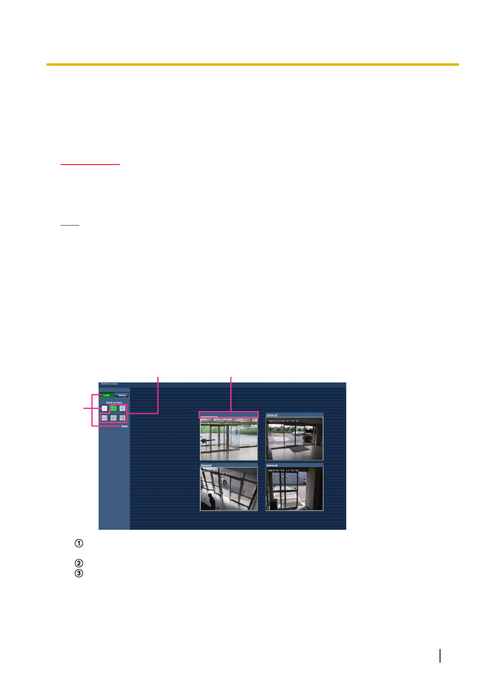
1. Click the desired [Multi-screen] on the “Live” page.
→Images from the registered cameras will be displayed on a selected multi-screen (screen can be split
up to 16 areas). The following are instructions when displaying on a 4-split screen.
WV- 31ASPN5 WV-SPN531A
C
A
B
WV- 31ASPN5
To show 1 camera screen, click the [Live] button.
You can also click “1” below “Multi-screen” or “Back” to display the camera's “Live” page.
Click the [Multi-screen] button to display images from cameras in a multi-screen of 4 to 16 screens.
Click a camera title. Live images from the camera corresponding to the clicked camera title will be
displayed on the “Live” page of the newly opened window.
Operating Instructions 17
1 Monitor images on a PC

2 Monitor images on a cellular phone/mobile
terminal
2.1 Monitor images on a cellular phone
It is possible to connect to the camera using a cellular phone via the Internet and monitor images (JPEG only)
from the camera on the screen of the cellular phone.
IMPORTANT
•When the authentication window is displayed, enter the user name and password. The default user
name and password are as follows.
User name: admin
Password: 12345
To enhance the security, change the password for the user “admin”. ( page 140)®
•If the cellular phone in use is not compatible with UTF-8 encode, it is impossible to display the screen
correctly.
•When “VGA”, “QVGA”, “640x360”, or “320x180” is not selected one time or more for either one of
“JPEG(1)”, “JPEG(2)”, or “JPEG(3)” of [JPEG] on the [JPEG/H.264] tab, images cannot be viewed from
cellular phones.
Note
•It is necessary to configure the network settings of the cellular phone in advance to connect to the
Internet and monitor images from the camera. ( page 145)®
•When “Auto” is selected for “Language”, the screen is displayed in English. If you want the screen to
be displayed in Japanese or Chinese, select “Japanese” or “Chinese” for “Language”. ( page 48)®
18 Operating Instructions
2 Monitor images on a cellular phone/mobile terminal
1. Access to “http://IP address/mobile” *1 or “http://Host name registered in the DDNS server/mobile” using a
cellular phone.
→Images from the camera will be displayed.
B
C
D
A
WV-SPN531A
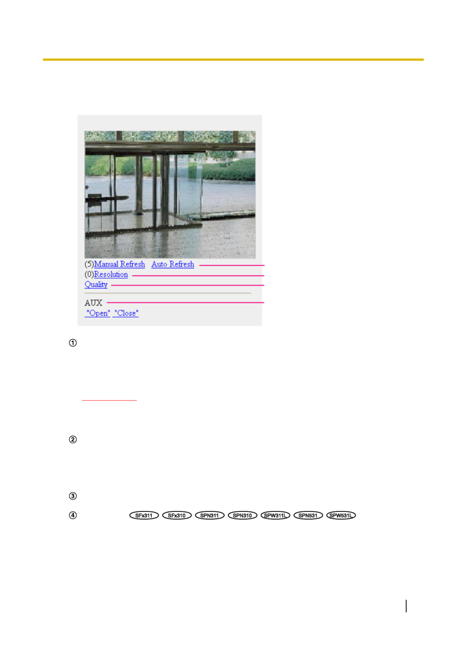
Refresh control
Press the dial key “5” or the [Manual Refresh] button to refresh the camera images.
Press the [Auto Refresh] button to refresh the images from the camera in 5-second intervals.
When the dial key “5” or the [Manual Refresh] button is pressed again, the refresh mode of the camera
will return to manual refresh.
IMPORTANT
•Transmission will be periodically performed when “Auto Refresh” is selected for the camera
image. Confirm the contract plan of the cellular phone in use before using this function.
•Depending on the cellular phone in use, “Auto Refresh” may be unavailable.
Resolution control
Changes the image capture size by pressing the dial key “0”.
•Image in the aspect ratio of “4:3”: Changes the image capture size between 320x240 (default) and
640x480.
•Image in the aspect ratio of “16:9”: Changes the image capture size between 320x180 (default)
and 640x360.
Image quality control
It is possible to change the image quality between “Quality1” and “Quality2”. ( page 77)®
AUX control*2
SFx311
SFx310
SPN311
SPN310
SPW311L
SPN531
SPW531L
Controls the AUX terminal.
These buttons will be displayed only when “AUX output” is selected for “Terminal 3” on the setup menu.
( page 116)®
Operating Instructions 19
2 Monitor images on a cellular phone/mobile terminal

Note
•Some cellular phones cannot change the image capture size even when resolution is changed by
resolution control.
•Depending on the image capture size selected for “JPEG(1)”, “JPEG(2)”, or “JPEG(3)”, “Resolution”
may not be able to be used.
•When the HTTP port number is changed from “80”, enter “http://IP address: (colon) + port number/
mobile”*1 in the address box of the browser. When using the DDNS function, access to “http://Host
name registered in the DDNS server: (colon) + port number/mobile”.
•When “HTTPS” is selected for “HTTPS” - “Connection” on the [Advanced] tab of the “Network” page,
enter as follows.
“https://IP address: (colon) + port number/mobile” or “https://Host name registered in the DDNS server:
(colon) + port number/mobile”
•When the authentication window is displayed, enter the user name of an administrator or user and
password. Depending on the cellular phone in use, password entry may be required each time the
screen is switched.
•It is impossible to transmit/receive audio using a cellular phone.
•Depending on the cellular phone in use, larger size images may not be displayed. In this case, selecting
“9 Low” for “Image quality setting” of “JPEG” ( page 77) may sometimes solve this problem.®
•Depending on the cellular phone in use or its contract plan, it may be impossible to access.
*1 IP address is the global WAN IP address of the router that can be accessed via the Internet.
*2 When “User auth.” is set to “On” ( page 140), only users with the access level of “1. Administrator” or “2. Camera control” will be®
displayed.
2.2 Monitor images on a mobile terminal
It is possible to connect to the camera using a mobile terminal via the Internet and monitor images (MJPEG
or JPEG) from the camera on the screen of the mobile terminal. It is also possible to refresh images to display
the latest image.
The compatible mobile terminals are shown as follows. (As of September, 2015)
–iPad, iPhone, iPod touch (iOS 4.2.1 or later)
–Android™ mobile terminals
When an Android terminal is used, an MJPEG format image is displayed by the Firefox ® browser, but a JPEG
format image is displayed by the standard browser.
For further information about compatible devices, refer to our website
(http://security.panasonic.com/pss/security/support/info.html).
IMPORTANT
•When the authentication window is displayed, enter the user name and password. The default user
name and password are as follows.
User name: admin
Password: 12345
To enhance the security, change the password for the user “admin”. ( page 140)®
Note
•It is necessary to configure the network settings of the mobile terminal in advance to connect to the
Internet and monitor images from the camera. ( page 145)®
20 Operating Instructions
2 Monitor images on a cellular phone/mobile terminal

1. Access to “http://IP address/cam” *1 or “http://Host name registered in the DDNS server/cam” using a mobile
terminal.
→Images from the camera will be displayed.
C
B
A
Live images area
Displays images from the camera.
Operation buttons area
When functions are selected in the function selection area , buttons to operate those functions areC
displayed.
Function selection area
When functions that can be operated are selected, operation buttons are displayed in the operation
buttons area .B
Operating Instructions 21
2 Monitor images on a cellular phone/mobile terminal

2. Click the button of the function that you want to operate.
A B
Resolution control
AUX control
SFx311
SFx310
SPN311
SPN310
SPW311L
SPN531
SPW531L
Each function is explained below.
Resolution control
Press the button to display the buttons used to select the resolution on the screen.
The resolution can be changed by selecting a resolution setting from the buttons.
Images are displayed in the image capture size selected in “JPEG(1)”, “JPEG(2)”, or “JPEG(3)” of
[JPEG] on the [JPEG/H.264] tab.
22 Operating Instructions
2 Monitor images on a cellular phone/mobile terminal

–Medium display: http://IP address/cam/dm
–Small display: http://IP address/cam/ds
•When the resolution is changed by the resolution control, the displayed resolution changes but the
image size remains the same.
•When the HTTP port number is changed from “80”, enter “http://IP address: (colon) + port number/
cam” *1 in the address box of the browser. When using the DDNS function, access to “http://Host name
registered in the DDNS server: (colon) + port number/cam” *2.
•When “HTTPS” is selected for “HTTPS” - “Connection” on the [Advanced] tab of the “Network” page,
enter as follows.
“https://IP address: (colon) + port number/cam” or “https://Host name registered in the DDNS server:
(colon) + port number/cam”
•When the authentication window is displayed, enter the user name of an administrator or user and
password. Depending on the mobile terminal in use, password entry may be required each time the
screen is switched.
•It is impossible to transmit/receive audio using a mobile terminal.
•Depending on the mobile terminal in use, larger size images may not be displayed. In this case,
selecting “9 Low” for “Image quality setting” of “JPEG” ( page 77) may sometimes solve this®
problem.
•Depending on the mobile terminal in use or its contract plan, it may be impossible to access.
*1 IP address is the global WAN IP address of the router that can be accessed via the Internet. However, when accessing the same
LAN as the camera with a wireless compatible mobile terminal, the IP address is the local IP address.
*2 Only when accessing the camera via the Internet.
24 Operating Instructions
2 Monitor images on a cellular phone/mobile terminal

3 Record images on the SD memory card
manually
Images displayed on the “Live” page can be recorded on the SD memory card manually. This button is operable
only when “Manual” is selected for “Save trigger” on the [SD memory card] tab on the “Basic” page of the setup
menu. ( page 58)®
It is possible to select “JPEG(1)”, “JPEG(2)”, “JPEG(3)”, “H.264(1)”, “H.264(2)”, “H.264(3)”, or “H.264(4)” on
“Recording format” of the setup menu. ( page 55) When “JPEG” is selected for “Recording format”, still®
image data are recorded. When “H.264(1)”, “H.264(2)”, “H.264(3)”, or “H.264(4)” is selected, video data are
recorded.
Images recorded on the SD memory card can be copied onto the PC. ( page 72)®
1. Display the “Live” page. ( page 8)®
WV-SPN531A WV-SPN531A
2. Click the [SD] button.
→The SD recording window will open.
3. Click the [Start] button to start recording images on the SD memory card. The SD recording status indicator
will light red ( page 10) while images are being recorded on the SD memory card.®
The image saving interval can be configured on the [SD memory card] tab of the “Basic” page.
( page 58)®
4. Click the [Stop] button to stop saving images on the SD memory card.
® The SD recording status indicator will turn off.
5. Click the [Close] button to close the window.
Note
•Image data saved on Drive B can be obtained by executing “Access img.” on the [SD memory card]
tab and logging in from the user authentication window ( page 72).®
The destination to save image data is a fixed directory on Drive B ( page 221).®
Operating Instructions 25
3 Record images on the SD memory card manually

•When the [Start] button is clicked immediately after the [Stop] button is clicked, saving of images may
not start. In this case, click the [Start] button again.
26 Operating Instructions
3 Record images on the SD memory card manually

4 Action at an alarm occurrence
The alarm action (camera action at an alarm occurrence) will be performed when the following alarms occur.
4.1 Alarm type
•Terminal alarm
SFx311
SFx310
SPN311
SPN310
SPW311L
SPN531
SPW531L
: When connecting an
alarm device such as a sensor to the alarm input terminal of the camera, the alarm action will be performed
when the connected alarm device is activated.
•VMD alarm: When motion is detected in the set VMD area, the alarm action will be performed.
*VMD stands for “Video Motion Detection”.
•Command alarm: When a Panasonic alarm protocol is received from the connected device via a network,
the alarm action will be performed.
•Audio detection alarm
SFx311
SPN311
SPW311L
SPN531
SPW531L
SFN310
SPN310
: When the
configured audio detection level is exceeded, the alarm action will be performed.
4.2 Action at an alarm occurrence
Display the alarm occurrence indication button on the “Live” page
The alarm occurrence indication button will be displayed on the “Live” page at an alarm occurrence.
( page 10)®
IMPORTANT
•When “Polling(30s)” is selected for “Alarm status update mode” ( page 48), the Alarm occurrence®
indication button will be refreshed in 30-second intervals. For this reason, it may take a maximum of
30 seconds until the alarm occurrence indication button is displayed on the “Live” page at an alarm
occurrence.
Notify of alarm occurrences to the device connected to the alarm connector
SFx311
SFx310
SPN311
SPN310
SPW311L
SPN531
SPW531L
It is possible to output signals from the alarm output terminal of the camera and sound the buzzer when an
alarm occurs. The settings for the alarm output can be configured in the “Alarm output terminal setup” section
of the [Alarm] tab of the “Alarm” page. ( page 118)®
Save images on the SD memory card
When an alarm occurs, images (JPEG/H.264) will be saved on the SD memory card. The settings to save
images on the SD memory card can be configured on the [SD memory card] tab ( page 55) of the “Basic”®
page and the [Alarm] tab of the “Alarm” page. ( page 120)®
Transmit an image onto a server automatically
An alarm image can be transmitted at an alarm occurrence to the server designated in advance. The settings
required to transmit an alarm image to a server can be configured in the “Alarm image” section on the
[Alarm] tab of the “Alarm” page ( page 120) and the [Advanced] tab of the “Network” page ( page 153).® ®
Operating Instructions 27
4 Action at an alarm occurrence

5 Transmit images onto an FTP server
Images can be transmitted to an FTP server. By configuring the following settings, transmission of images
captured at an alarm occurrence or captured at a designated interval to an FTP server will become available.
IMPORTANT
•When using this function, set the user name and the password to access the FTP server to restrict
users who can log into the FTP server.
5.1 Transmit an alarm image at an alarm occurrence
(Alarm image transmission)
An alarm image can be transmitted at an alarm occurrence to the FTP server. To transmit alarm images to an
FTP server, it is necessary to configure the settings in advance.
FTP server settings and settings relating to alarm image transmission can be configured in the “FTP” section
of the [Advanced] tab of the “Network” page. ( page 153) Settings can also be configured from the “Alarm®
image FTP transmission” settings of “Camera action on alarm” on the [Alarm] tab of the “Alarm” page.
( page 120)®
Note
•Depending on the network traffic, the number of the transmitted images may not reach the set number
of images to be transmitted.
•Alarm images failed to be transmitted to the FTP server at an alarm occurrence will not be saved on
the SD memory card. However, images that fail to be transmitted with the FTP periodic image
transmission will be saved.
When “On” is selected for both the alarm image transmission function and the FTP periodic image
transmission function, the alarm image transmission function will be given priority over the FTP periodic
image transmission function. Also, when “On” is selected for the “FTP transmission retry” FTP setting
( page 154), alarm images will be retransmitted if there is an FTP transmission failure. Therefore, if®
there is continuous retransmission due to network problems or other factors, periodic transmission will
not be performed and images that fail to be transmitted with the FTP periodic image transmission will
not be saved to an SD memory card.
5.2 Transmit images at a designated interval or
period (FTP periodic image transmission)
Images can be transmitted at a designated interval or period. To transmit images at a designated interval or
period, it is necessary to configure the settings in advance.
FTP server settings and settings relating to FTP periodic transmission image transmission can be configured
in the “FTP” section of the [Advanced] tab of the “Network” page. ( page 153)®
Configure the schedule settings of the FTP periodic image transmission on the “Schedule” page.
( Page 187)®
Note
•Depending on the line speed or the traffic, images may not be transmitted at the designated interval.
•When “On” is selected for both the alarm image transmission function and the FTP periodic image
transmission function, the alarm image transmission function will be given priority over the FTP periodic
Operating Instructions 29
5 Transmit images onto an FTP server

6 Display the log list
The history of various logs will be displayed in list form.
•Alarm log: Logs of the alarm occurrences such as time and date of the alarm occurrences, the image
recording period and the alarm type will be displayed.
•Manual/Schedule log: Logs filed when images have been recorded manually or during the period of the
schedule, and the image recording period will be displayed.
•FTP trans. error log: Logs filed when the FTP periodic image transmission function has failed will be
displayed.
1. Display the “Live” page.
WV-SPN531A WV-S 31APN5
Operating Instructions 31
6 Display the log list
2. Click the [List/Play] button.
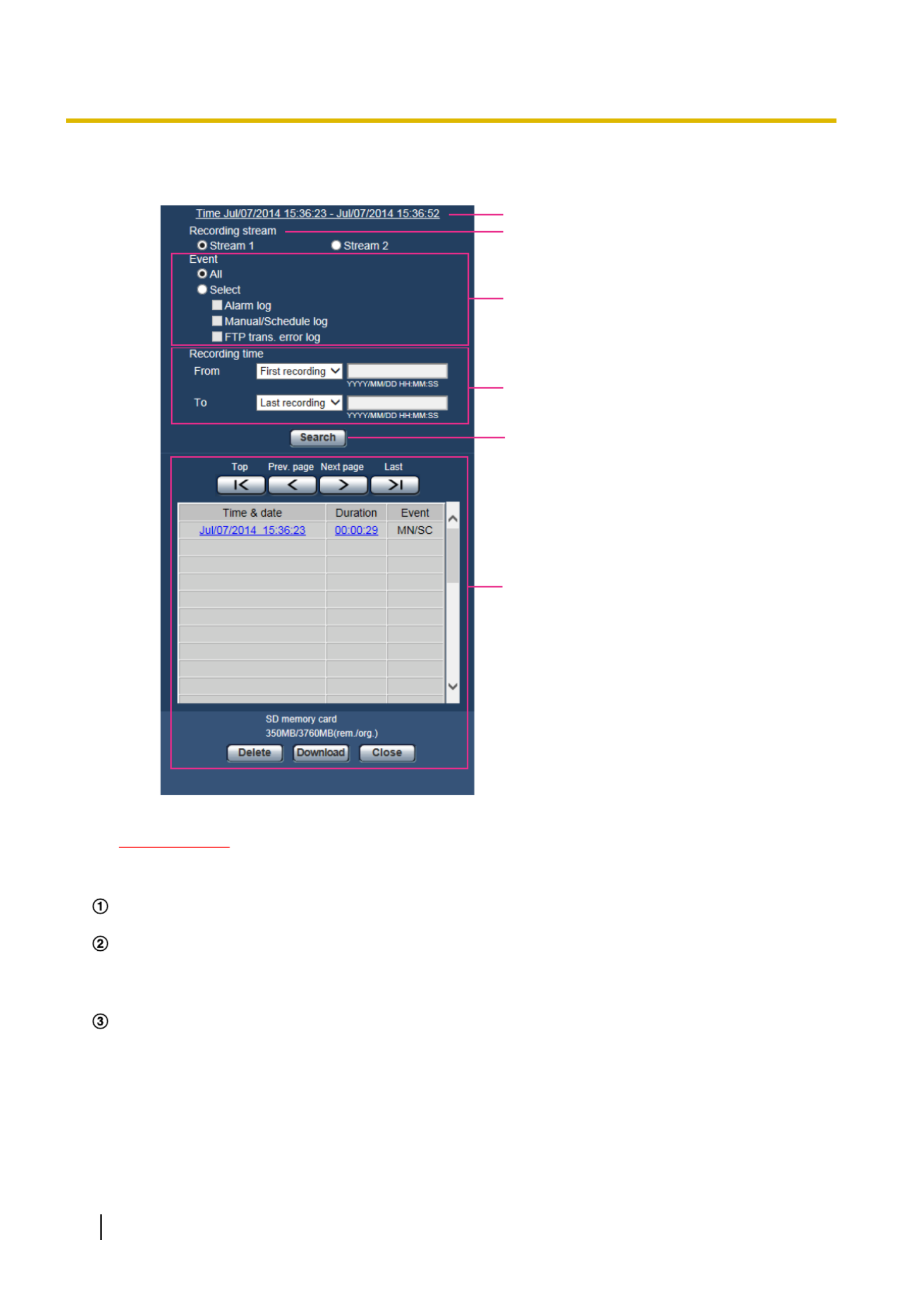
→The log list will be displayed in a newly opened window (log list window).
A
B
E
D
F
C
IMPORTANT
•Only a single user can operate the log list window. Other users cannot access the log list window.
Time
Displays the time period of the data recorded on the SD memory card.
Recording stream
Select the recording stream that you want to display logs for.
•Stream 1: The logs recorded by “Recording stream 1” on the [SD memory card] tab will be displayed.
•Stream 2: The logs recorded by “Recording stream 2” on the [SD memory card] tab will be displayed.
Event
Select a log type to display on the log list.
•All: All logs will be displayed.
•Select: Only the logs of the selected log type will be displayed.
–Alarm log: The log when an alarm is detected will be displayed.
–Manual/Schedule log: Manual and Schedule logs will be displayed.
–FTP trans. error log: Logs filed when the FTP periodic image transmission function has failed will
be displayed.
32 Operating Instructions
6 Display the log list

•Default: All
Note
•When “Stream 1” is selected for “Recording stream” and either “JPEG(1)”, “JPEG(2)”, or
“JPEG(3)” is selected for “Stream 1”, the FTP trans. error log will be displayed.
Recording time
Configure the time period of logs displayed on the log list.
•From: Configure the starting period of logs displayed on the log list.
–First recording: Displays from the first log recorded on the SD memory card.
–Today: Displays the logs recorded today.
–Yesterday: Displays the logs recorded from yesterday to the present day.
–Last 7 days: Displays the logs recorded from 6 days ago to the present day.
–Last 30 days: Displays the logs recorded from 29 days ago to the present day.
–Date/time: Displays the logs recorded from the entered date and time on “Date/time” box.
•To: Configure the ending period of logs displayed on the log list when “First recording” or “Date/time”
is selected for “From”.
–Last recording: Displays until the last log recorded on the SD memory card.
–Date/time: Displays the logs recorded until the entered date and time on “Date/time” box.
[Search] button
Searches for logs according to the conditions specified in “Event” and “Recording time”.
The search result will be displayed on the log list.
Log list
Displays the log search results.
You can play back recorded data by clicking on the time or duration of the recorded data displayed under
[Time] and [Duration].
•[Top] button: Click this button to display the log listed at the top.
•[Prev. page] button: Click this button to display the previous page of the log list.
•[Next page] button: Click this button to display the next page of the log list.
•[Last] button: Click this button to display the log listed at the bottom.
•[Time & date]: Time and date when each log has been recorded will be displayed.
Note
•When “Off” is selected for “Time display format”, the alarm occurrence times are displayed in
24 hour time format.
•The recording timing of logs is as follows.
–Alarm log: Alarm occurrence time and date will be filed as a log.
–Manual/Schedule log: Time and date when recording of images onto the SD memory card
started manually or during the period of the schedule will be filed as a log. When images
are recorded sequentially, if “JPEG” is selected for “Recording format”, logs will be filed on
the hour every hour (12:00, 1:00, 2:00, etc.). If “H.264” is selected for “Recording format”,
logs will be filed every hour from the time when recording starts. However, depending on
the photographic subject and the setting used, logs may be filed in periods of over an hour.
–FTP trans. error log: Logs will be filed every one hour.
•[Duration]: Displays the period of time that the data has been recorded on the SD memory card.
Note
•The difference between the recording end time and recording start time of the image is
calculated by rounding off to the nearest tenth of a second. For this reason, when only 1 JPEG
image is saved, 00:00:00 is displayed for the duration.
•[Event]: The event type will be displayed.
–MN/SC: Log by “Manual/Schedule”
–TRM1: Alarm by alarm input to Terminal 1
Operating Instructions 33
6 Display the log list

–TRM2: Alarm by alarm input to Terminal 2
–TRM3: Alarm by alarm input to Terminal 3
–VMD: Alarm by VMD alarm
–COM: Alarm by command alarm
–AUD: Alarm by audio detection alarm
–FTP: Logs saved from FTP periodic image transmission errors
•[SD memory card]: Available capacity and the original capacity of the SD memory card will be
displayed.
•[Delete] button: Click this button to delete the currently displayed log list. When using the SD memory
card, images associated with the log list will also be deleted.
IMPORTANT
•If there are too many recorded data files, it may take time to delete all of them. (When the total
size is 1 GB, it may require about 1 hour.) Formatting the SD memory card can shorten the
time to delete all the data.
•In the process of the deletion, “Alarm” and “Manual/Schedule” cannot be operated.
•Do not turn off the power of the camera until the deletion is complete. When the power of the
camera is turned off in the process of the deletion, some images may remain on the SD memory
card. In this case, click the [Delete] button on the same log list window used to delete the logs.
•[Download] button: Click this button to download all logs of the selected log list onto the PC.
Note
•The following settings may be required.
Open Internet Explorer, click [Tools] [Internet Options] [Security] [Trusted Sites] ® ® ® ®
[Sites]. Register the camera address on [Website] of the displayed trusted windows.
After registration, close the web browser, and then access the camera again.
•Up to 50,000 logs will be downloaded to the SD memory card. When more than 50,000 logs
are filed, the older logs will be overwritten by the newer logs. In this case, the oldest log is the
first to be overwritten.
•[Close] button: Click this button to close the log list window.
34 Operating Instructions
6 Display the log list

7 Playback of images on the SD memory card
When clicking a time and date listed on the log list window, the “Live” page will turn to the “Playback” page.
When images associated with the clicked time and date are on the SD memory card, the first image of them
will be displayed.
The display format varies depending on the “Recording format” of the SD memory card.
IMPORTANT
•Refresh interval of images may become slow during playback or download.
•When many images are saved on the SD memory card, it may take time to display images on the
“Playback” page.
•Images will be displayed in VGA size on the “Playback” page regardless of the image capture size of
the images saved on the SD memory card. When the aspect ratio is “16:9”, images will be displayed
in “640x360” on the “Playback” page regardless of the image capture size of the images saved on the
SD memory card. Therefore, images may look coarse on the “Playback” page.
•When playing images by selecting an FTP error log on the log list, images may not be played in order
of images recorded on the SD memory card if they have been recorded on the SD memory card with
selected value for the “Transmission interval” setting of “FTP periodic image transmission” on the
[Advanced] tab is “1min” or less.
•The playback refresh interval may become slower when recording data to the SD memory card.
7.1 Playback “JPEG(1)”/“JPEG(2)”/“JPEG(3)”
images saved to the SD memory card
A
Number of images
When clicking a time and date listed on the log list window, total number of images associated with the
clicked time and date, and the number of the currently displayed image will be displayed.
Note
•Enter the desired number of image and press the [Enter] key on the keyboard. The image of the
designated number will be displayed.
[REW] button
Each time the button is clicked, the playback speed will change.
Operating Instructions 35
7 Playback of images on the SD memory card

Select the image to be downloaded, and then click the [OK] button.
•All: All images saved at the selected time and date will be downloaded.
•Current image: Only the currently displayed image will be downloaded.
•Download range: Images in the specified range will be downloaded.
Note
•When the [Cancel] button is clicked in the process of the download, the download will be canceled. In
this case, images already downloaded before clicking the [Cancel] button will be saved on the PC.
[Browse] button
When successfully logged in after the user authentication process, a folder on the SD memory card in which
images are saved will be displayed. ( page 72)®
Operating Instructions 37
7 Playback of images on the SD memory card

7.2 Playback “H.264(1)”/“H.264(2)”/“H.264(3)”/“H.
264(4)” images saved to the SD memory card
IMPORTANT
•Depending on the network environment, download of video data may fail.
A
Slider bar
By operating the slider bar, you can select where to start playing images from. The slider bar can only be
used before playing images, or when playing is paused or stopped.
[PAUSE] button
Playback will be paused when this button is clicked during playback.
[PLAY] button
When this button is clicked, recorded data will be played.
Note
•If audio is recorded, it can be played back, but the image and audio will not be synchronized. Therefore,
images and audio may not always match. When data is being recorded to the SD memory card, audio
may sound as if it is cutting out and the audio quality may be reduced.
•When recorded audio is played back, the refresh interval of live images and playback may become
slow.
•Recorded audio is not played back when “Off” or “Interactive(Half-duplex)” is selected for “Audio
mode” on the [Audio] tab of the “Image/Audio” page.
•Audio is only played for users who belong to the access level selected for “Permission level of audio
trans./recep.” on the [Audio] tab of the “Image/Audio” page.
[FF] button
Each time this button is clicked, the playback speed will change. When the [PLAY] button is clicked during fast
playback, playback speed will return to the normal playback speed.
38 Operating Instructions
7 Playback of images on the SD memory card

Note
•The maximum speed of the fast playback varies depending on the setting of “Max bit rate” - “H.264
recording” of the SD memory card. If any of the following also applies to “Transmission priority” or “Max
bit rate (per client)” on the [JPEG/H.264] tab of the “Image/Audio” page, playback speed becomes
constant (x1), not fast playback.
–When “Frame rate” or “Advanced VBR” is selected for “Transmission priority”, and “14436kbps” or
a higher value is selected for the maximum value of “Max bit rate (per client)”
–When “Constant bit rate” is selected for “Transmission priority”, and “16384kbps” is selected for
the maximum value of “Max bit rate (per client)”
•Recorded audio will not be played back during fast playback.
[5s backward] button
Each time this button is clicked, the recorded data goes back by 5 seconds and starts playing.
[5s forward] button
Each time this button is clicked, the recorded data goes forward by 5 seconds and starts playing.
[STOP] button
Playback will stop and the “Playback” window will turn to the “Live” page.
[Time]
Time and date when each log has been recorded will be displayed.
[Duration]
Displays the period of time that the data has been recorded on the SD memory card.
[Event]
The event type will be displayed.
•MN/SC: Log by “Manual/Schedule”
•TRM1: Alarm by alarm input to Terminal 1
•TRM2: Alarm by alarm input to Terminal 2
•TRM3: Alarm by alarm input to Terminal 3
•VMD: Alarm by VMD alarm
•COM: Alarm by command alarm
•AUD: Alarm by audio detection alarm
Browse
[Start] button
The selected image will be downloaded onto the PC.
Before downloading images, designate the destination directory in advance. ( page 74)®
The message window will be displayed to ask if it is OK to start download when the [Start] button is clicked.
Click the [OK] button.
Note
•When the [Cancel] button is clicked in the process of the download, the download will be canceled. In
this case, video data already downloaded before clicking the [Cancel] button will be saved on the PC.
•Video data are saved in the files of approx. 20 MB. When the file size of video data is more than 20
MB, two or more files will be downloaded.
•It is possible to play back video data saved on the PC using such applications as QuickTime Player or
Windows Media® Player*1. However, we are not liable for performance relating to these applications.
Operating Instructions 39
7 Playback of images on the SD memory card

•Depending on the status of the SD memory card, QuickTime Player, or Windows Media Player, video
data cannot be played back.
*1 The supported operating systems are Windows 8.1, Windows 8, and Windows 7 only.
40 Operating Instructions
7 Playback of images on the SD memory card

8 About the network security
8.1 Equipped security functions
The following security functions are featured in this camera.
Access restrictions by the host authentication and the user authentication
It is possible to restrict users from accessing the camera by setting the host authentication and/or the user
authentication to “On”. ( page 140, page 141)®
Access restrictions by changing the HTTP port
It is possible to prevent illegal access such as port scanning, etc. by changing the HTTP port number.
( page 147)®
Access encryption by the HTTPS function
It is possible to enhance the network security by encrypting the access to cameras using the HTTPS
function. ( page 164)®
IMPORTANT
•Design and enhance security countermeasures to prevent leakage of information such as image data,
authentication information (user name and password), alarm E-mail information, FTP server
information, DDNS server information, etc. Perform the countermeasure such as access restriction
(using the user authentication) or access encryption (using the HTTPS function).
•After the camera is accessed by the administrator, make sure to close the browser for added security.
•Change the administrator password periodically for added security.
Note
•When user authentication (authentication error) has failed to pass 8 times within 30 seconds using the
same IP address (PC), access to the camera will be denied for a while.
Operating Instructions 41
8 About the network security
9 Display the setup menu from a PC
The settings of the camera can be configured on the setup menu.
IMPORTANT
•The setup menu is only operable by users whose access level is “1. Administrator”. Refer to
page 140 for how to configure the access level.
9.1 How to display the setup menu
1. Display the “Live” page. ( page 8)®
2. Click the [Setup] button on the “Live” page.
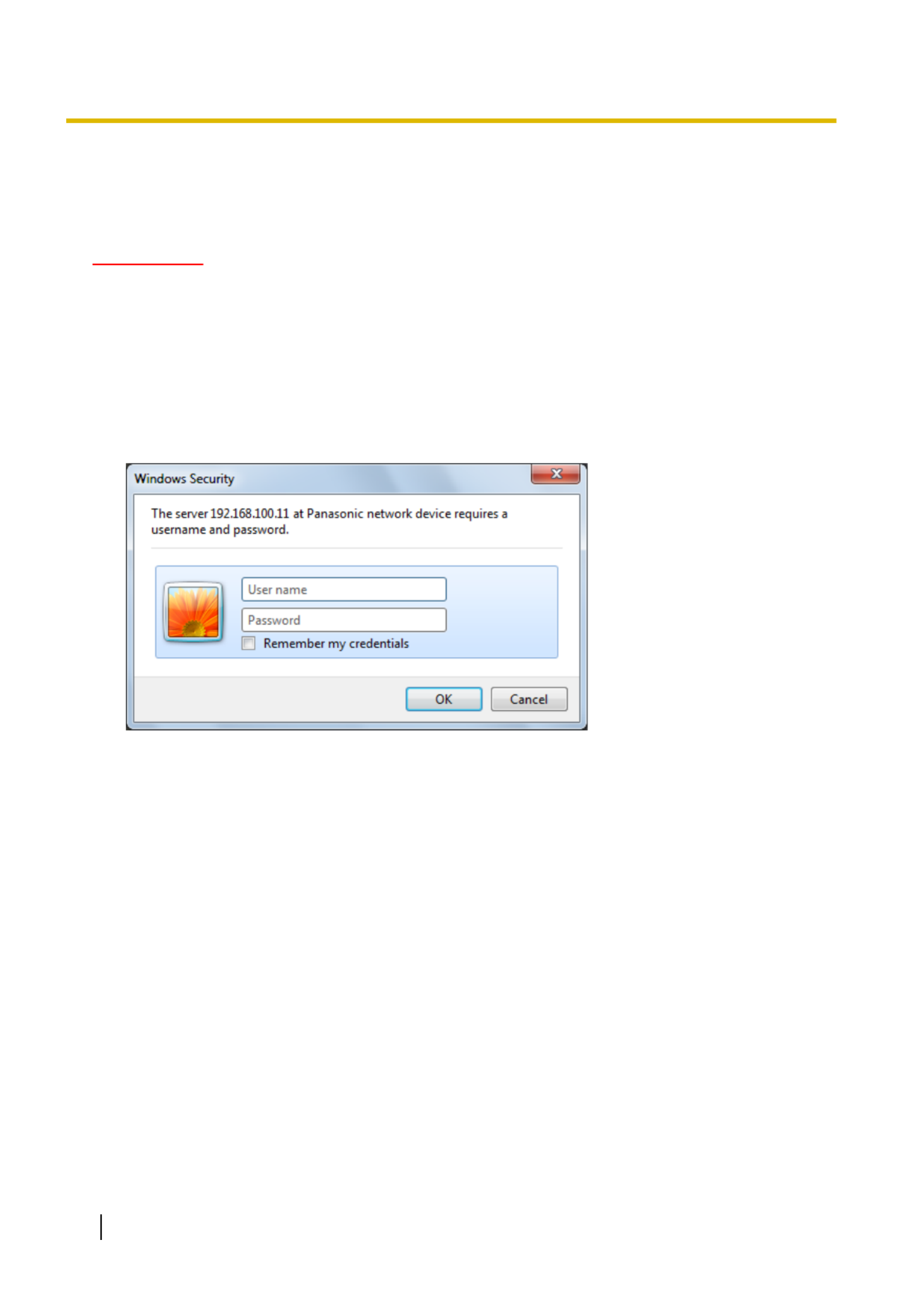
→The window with the user name and password entry fields will be displayed.
3. Click the [OK] button after entering the user name and the password.
The default user name and password are as follows.
User name: admin
Password: 12345
42 Operating Instructions
9 Display the setup menu from a PC
→The setup menu will be displayed. Refer to page 46 for further information about this menu.
Operating Instructions 43
9 Display the setup menu from a PC

9.2 How to operate the setup menu
A B
WV-SPN531A WV-S 1APN53
Menu buttons
Setup page
1. Click the desired button in the frame on the left of the window to display the respective setup menu.
When there are tabs at the top of the “Setup” page displayed in the frame on the right of the window, click
the desired tab to display and configure the setting items relating to the name of the tab.
2. Complete each setting item displayed in the frame on the right of the window.
3. After completing each setting item, click the [Set] button to apply them.
IMPORTANT
•When there are two or more [Set] and [Execute] buttons on the page, click the respective button to the
edited setting item.
44 Operating Instructions
9 Display the setup menu from a PC

<Example>
A
B
C
D
When completing the setting items in field , click the [Set] button ( ) below field ( ).A B A
The edited settings in field A will not be applied unless the [Set] button ( ) below field ( ) is clicked.B A
In the same manner as above, click the [Set] button ( ) below field when completing the settingD C
items in field .C
Operating Instructions 45
9 Display the setup menu from a PC

9.3 About the setup menu window
A
B
C
E
F
G
H
I
D
J
K
M
L
[Setup] button
Display the “Setup” page.
[Live] button
Display the “Live” page.
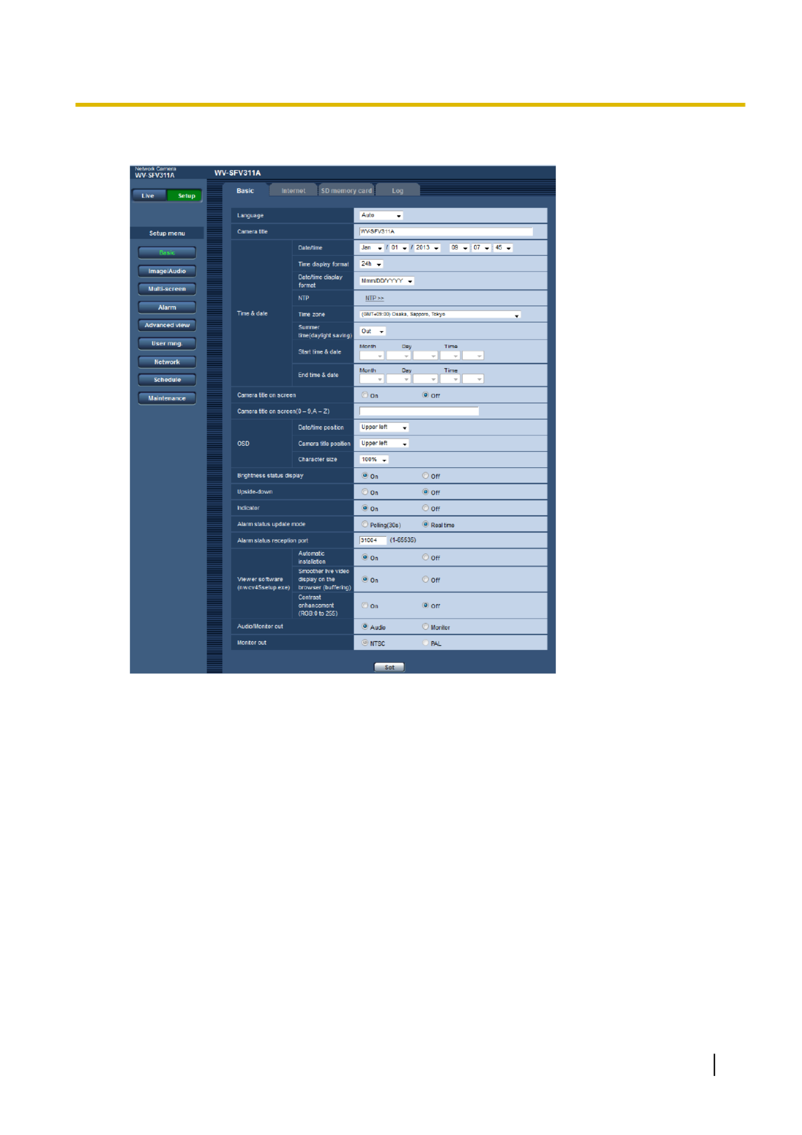
[Basic] button
Displays the “Basic” page. The basic settings such as time and date and camera title, and the settings
relating to the SD memory card can be configured on the “Basic” page. ( page 48)®
46 Operating Instructions
9 Display the setup menu from a PC

[Image/Audio] button
Displays the “Image/Audio” page. The settings relating to image quality, image capture size, etc. of JPEG/
H.264 camera images can be configured on the “Image/Audio” page. ( page 76)®
[Multi-screen] button
Displays the “Multi-screen” page. The cameras from which images are to be displayed on a multi-screen
can be registered on the “Multi-screen” page. ( page 114)®
[Alarm] button
Displays the “Alarm” page. The settings relating to alarm occurrences such as settings for the alarm action
at an alarm occurrence, the alarm occurrence notification, and the VMD area settings can be configured
on the “Alarm” page. ( page 116)®
[Advanced view] button
Displays the “Advanced view” page. The settings relating to cropping can be configured on the “Advanced
view”. ( page 137)®
[User mng.] button
Displays the “User mng.” page. The settings relating to the authentication such as users and PCs
restrictions for accessing the camera can be configured on the “User mng.” page. ( page 140)®
[Network] button
Displays the “Network” page. The network settings and the settings relating to DDNS (Dynamic DNS),
SNMP (Simple Network Management Protocol), FTP (File Transfer Protocol), the NTP server, and Diffserv
can be configured on the “Network” page. ( page 145)®
[Schedule] button
Displays the “Schedule” page. On the “Schedule” page, it is possible to designate time zones to allow to
receive alarm input or to allow to activate the VMD detection function. ( page 184)®
[Maintenance] button
Displays the “Maintenance” page. System log check, firmware upgrade, status check and initialization of
the setup menu can be carried out on the “Maintenance” page. ( page 191)®
Camera title
The title of the camera whose settings are currently being configured will be displayed.
Setup page
Pages of each setup menu will be displayed. There are tabs for some setup menus.
Operating Instructions 47
9 Display the setup menu from a PC

The language displayed on the “Live” page can also be changed. ( page 10)®
[Camera title]
Enter the title of the camera. Click the [Set] button after entering the title of the camera. The entered title will
be displayed in the “Camera title” field.
•Available number of characters: 0 - 20 characters
•Unavailable characters: " &
•Default: The model No. is displayed.
[Date/time]
Enter the current time and date. When “12h” is selected for “Time display format”, “AM” or “PM” can be selected.
•Available range: Jan/01/2013 00:00:00 - Dec/31/2035 23:59:59
IMPORTANT
•Use an NTP server when the more accurate time & date setting is required for the system operation.
( page 157)®
[Time display format]
Select the time display format from “24h”, “12h” and “Off”. Enter the current hour reflecting this setting when
entering the current time and date for “Date/time”. To hide time and date, select “Off”.
•Default: 24h
[Date/time display format]
Select a date/time display format. When “2015/04/01 13:10:00” is set for “Date/time” after selecting “24h” for
“Date/time display format”, time & date will be respectively displayed as follows.
•DD/MM/YYYY: 01/04/2015 13:10:00
•MM/DD/YYYY: 04/01/2015 13:10:00
•DD/Mmm/YYYY: 01/Apr/2015 13:10:00
•YYYY/MM/DD: 2015/04/01 13:10:00
•Mmm/DD/YYYY: Apr/01/2015 13:10:00
•Default: Mmm/DD/YYYY
[NTP]
When “NTP >>” is clicked, the [Advanced] tab of the “Network” page will be displayed. ( page 157)®
[Time zone]
Select a time zone corresponding to the location where the camera is in use.
•Default: (GMT +09:00) Osaka, Sapporo, Tokyo
[Summer time (daylight saving)]
Select “In”, “Out” or “Auto” to determine whether or not to apply daylight saving time. Configure this setting if
the summer time (daylight saving time) is applied in the location where the camera is in use.
•In: Applies summer time. An asterisk (*) will be displayed on the left side of the displayed time and date.
•Out: Does not apply summer time.
•Auto: Applies summer time in accordance with the settings for “Start time & date” and “End time &
date” (month, week, day of the week, time).
•Default: Out
[Start time & date] [End time & date]
When “Auto” is selected for “Summer time (daylight saving)”, select the time & date for the start time and the
end time (month, week, day of the week, time).
Operating Instructions 49
10 Configure the basic settings of the camera [Basic]

•Default: On
[Upside-down]
Select “On” or “Off” to determine whether or not to turn the image upside-down.
•Default: Off
[Indicator]
Determine whether or not to use the following indicators. Select “On” to use the following indicators to check
the operational status by lighting them. Select “Off” to turn off the indicators at all times.
–Link indicator (LINK)
–Access indicator (ACT)
–SD memory card error indicator/AF indicator (SD ERROR/AF)
SFx311
SFx310
SPW311L
SPW531L
SPW312L
SPW532L
–SD memory card error indicator/ABF indicator (SD ERROR/ABF)
SPN311
SPN531
–SD memory card error indicator/F.A. indicator (SD ERROR/F.A.)
SPN310
–SD MOUNT indicator (SD MOUNT)
•Default: On
Note
•Link indicator (LINK) (orange): This indicator will light when communication with the connected
device is available.
•Access indicator (ACT) (green): This indicator will blink when accessing a network.
•SD memory card error indicator/AF indicator (SD ERROR/AF)
SFx311
SFx310
SPW311L
SPW531L
SPW312L
SPW532L
(red): Lights when an error occurred in the SD memory card. This LED
will blink in the process of the auto focus function and blinking will stop when the focus adjustment is
complete. Except when the auto back focus is being used or when the indicator lights, it indicates that
an error occurred in the SD memory card.
•SD memory card error indicator/ABF indicator (SD ERROR/ABF)
SPN311
SPN531
(red): Lights
when an error occurred in the SD memory card. This LED will blink in the process of the auto back
focus function and blinking will stop when the focus adjustment is complete. Except when the auto back
focus is being used or when the indicator lights, it indicates that an error occurred in the SD memory
card.
•SD memory card error indicator/F.A. indicator (SD ERROR/F.A.)
SPN310
(red): Lights when an
error occurred in the SD memory card. This LED will blink once in the process of the focus assist
function and light when the focus assist is complete. Except when the auto focus is being used, when
the indicator lights or blinks, it indicates that an error occurred in the SD memory card.
•SD MOUNT indicator (SD MOUNT) (green): Lights when data can be saved to the SD memory card.
It blinks or is off when data cannot be saved to the SD memory card.
–Indicator is off: Indicates “Not use” is selected for the SD memory card, or an error occurred for
the SD memory card.
–Indicator blinks: Indicates the SD memory card is being recognized or is performing the necessary
processing for the SD memory card to be removed.
–Indicator lights: Indicates data can be saved to the SD memory card.
[Alarm status update mode]
Select an interval of the camera status notification from the following.
When the status of the camera changes, the alarm occurrence indication button, the [AUX] button or the SD
saving status indicator will be displayed to notify of the camera status.
•Polling(30s): Updates the status each 30 seconds and provide notification of the camera status.
•Real time: Provide notification of the camera status when the status has changed.
•Default: Real time
Operating Instructions 51
10 Configure the basic settings of the camera [Basic]

Note
•Depending on the network environment, notification may not be provided in real time.
•When multiple cameras are using the same “Alarm status reception port”, even if “Real time” is selected
for “Alarm status update mode”, status notification is not provided in real time. In this case, change the
“Alarm status reception port” settings.
[Alarm status reception port]
When selecting “Real time” for “Alarm status update mode”, designate a port number to which the status change
notification is to be sent.
•Available port number: 1 - 65535
•Default: 31004
The following port numbers are unavailable since they are already in use.
20, 21, 23, 25, 42, 53, 67, 68, 69, 80, 110, 123, 161, 162, 443, 995, 10669, 10670
[Viewer software (nwcv4Ssetup.exe)] - [Automatic installation]
Determine whether or not to install the viewer software from this camera.
•On: Installs the viewer software from the camera automatically.
•Off: The viewer software cannot be installed from the camera.
•Default: On
[Viewer software (nwcv4Ssetup.exe)] - [Smoother live video display on the browser
(buffering)]
Perform settings to display camera images on the viewer software.
•On: Images are temporarily stored on the computer and are displayed smoother.
•Off: Images are displayed in real-time and are not stored on the computer.
•Default: On
IMPORTANT
•It is impossible to display images and to receive/transmit audio between the camera and the PC when
the viewer software “Network Camera View 4S” is not installed on the PC.
•The number of the viewer software installations can be checked on the [Upgrade] tab of the
“Maintenance” page.
[Contrast enhancement(RGB:0 to 255)]
Select “On” or “Off” to determine whether or not to enhance the contrast of H.264 images on the “Live” page.
If “On” is selected, the range of RGB signal on display is extended from 16-235 to 0-255.
When there is a bright part in an image, the intensity may be overexposed.
Default: Off
Note
•This setting is only available when viewing images on the “Live” page with Internet Explorer.
•Even if this setting is changed, transmitted image data and data saved on the SD memory card are not
changed.
[Audio/Monitor out]
SFx311
SPW311L
SPW531L
Set the Audio/Monitor output format.
Audio/Monitor
Default: Audio
Note
•When “Audio/Monitor out” is set to “Audio”, “Monitor out” cannot be selected.
•When “Audio mode” is set to anything other than “Off” or “Mic input”, “Audio/Monitor out” cannot be set
to “Monitor”.
52 Operating Instructions
10 Configure the basic settings of the camera [Basic]

•When “Audio/Monitor out” is set to “Monitor”, “Audio mode” can only be set to “Off” or “Mic input”.
[Monitor out]
Set the monitor output method.
NTSC/PAL
Default: NTSC
10.2 Configure the Internet settings [Internet]
Click the [Internet] tab of the “Basic” page. ( page 42, page 44)®
The settings relating to UPnP (Auto port forwarding), DDNS (Viewnetcam.com), and network settings for the
Internet can be configured on this page.
[UPnP (Auto port forwarding)]
Select “On” or “Off” to determine whether or not to use the port forwarding function of the router.
To use the auto port forwarding function, the router in use must support UPnP and the UPnP must be enabled.
•Default: Off
Note
•Due to auto port forwarding, the port number may sometimes be changed. When the number is
changed, it is necessary to change the port numbers registered in the PC and recorders, etc.
•The UPnP function is available when the camera is connected to the IPv4 network. IPv6 is not
supported.
•To check if auto port forwarding is properly configured, click the [Status] tab on the “Maintenance” page,
and check that the “Enable” is displayed for “Status” of “UPnP”. ( page 193)®
When “Enable” is not displayed, refer to “Cannot access the camera via the Internet.” in
21 Troubleshooting.
•When the “UPnP (Auto port forwarding)” setting is changed, the “Auto port forwarding” setting under
“UPnP” on the [Advanced] tab of the “Network” page also changes to the same setting.
[Area]
Select the region where the camera is installed. If the camera is used outside of Japan, select “Global”. If the
camera is used in Japan, select “Japan”.
Japan/Global
[Service]
Select “Viewnetcam.com” or “Off” to determine whether or not to use “Viewnetcam.com”.
By selecting “Viewnetcam.com” and clicking the [Set] button, the registration window for “Viewnetcam.com”
will be displayed in a newly opened window.
Follow the on-screen instructions to register with “Viewnetcam.com”.
Operating Instructions 53
10 Configure the basic settings of the camera [Basic]

Refer to page 181 or the “Viewnetcam.com” website (http://www.viewnetcam.com/) for further information.
•Default: Off
Note
•When the “DDNS” setting is changed, the “DDNS” setting on the [Advanced] tab of the “Network” page
also changes to the same setting.
[Recommended network setting for internet]
The recommended settings for connecting to the Internet are performed here.
By clicking the [Set] button, a dialog displaying how the following settings will change is displayed.
Click the [OK] button after checking the settings to change the settings to the displayed values.
–[JPEG/H.264] tab on the “Image/Audio” page
[JPEG(1)]
[Image capture size]: VGA/640x360
[JPEG(2)]
[Image capture size]: QVGA/320x180
[JPEG(3)]
[Image capture size]: 160x120/160x90
[H.264(1)]/[H.264(2)]/[H.264(3)]/[H.264(4)]
[Internet mode (over HTTP)]: On
[Transmission priority]: Best effort
[Max bit rate (per client)*]: Max. 1024 kbps, Min. 128 kbps
[H.264(1)]
[Image capture size]: 1280x960/1280x720/1920x1080
[Max bit rate (per client)*]: Max. 1024 kbps, Min. 256 kbps
[H.264(2)]
[Image capture size]: VGA/640x360
[Max bit rate (per client)*]: Max. 1024 kbps, Min. 128 kbps
[H.264(3)]
[Image capture size]: QVGA/320x180
[Max bit rate (per client)*]: Max. 1024 kbps, Min. 128 kbps
[H.264(4)]
[Image capture size]: 160x120/160x90
[Max bit rate (per client)*]: Max. 1024 kbps, Min. 128 kbps
–[Network] tab on the “Network” page
[Common]
[Max RTP packet size]: Limited(1280byte)
[HTTP max segment size(MSS)]: Limited(1280byte)
54 Operating Instructions
10 Configure the basic settings of the camera [Basic]
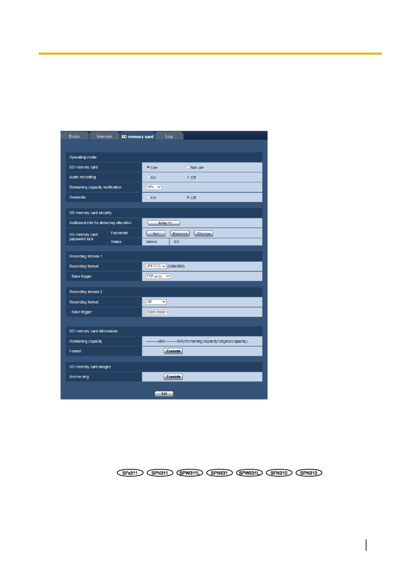
10.3 Configure the settings relating to the SD
memory card [SD memory card]
Click the [SD memory card] tab on the “Basic” page. ( page 42, page 44)®
The settings relating to the SD memory card can be configured on this page.
Operating mode
[SD memory card]
Select “Use” or “Not use” to determine whether or not to use the SD memory card.
•Default: Use
[Audio recording]
SFx311
SPN311
SPW311L
SPN531
SPW531L
SFN310
SPN310
Select whether or not to save audio data when saving video data in MP4 format.
•Off: Does not save audio data to videos (MP4 format).
•On: Saves audio data (AAC-LC format) to videos (MP4 format).
Default: Off
Operating Instructions 55
10 Configure the basic settings of the camera [Basic]

[SD memory card password lock]
Configure a password for the SD memory card. When configuring a password, devices other than the camera
will be unable to write to or read the SD memory card. If the SD memory card is stolen or lost, the risk of
recorded data being leaked can be reduced.
[Set]
When an SD memory card with no configured password is inserted, a password can be configured using the
[Set] button.
[Password]/[Retype password]
Enter the password.
•Available number of characters: 4 - 16 characters
•Unavailable characters: " &
•Default: None (blank)
[Remove]
When an SD memory card with a configured password is inserted, the password can be removed using the
[Remove] button.
[Password]
Enter the password.
•Available number of characters: 4 - 16 characters
•Unavailable characters: " &
[Change]
When an SD memory card with a configured password is inserted, the password can be changed using the
[Change] button.
[Old password]/[New password]/[Retype new password]
Enter the password.
•Available number of characters: 4 - 16 characters
Operating Instructions 57
10 Configure the basic settings of the camera [Basic]

•Unavailable characters: " &
[Status]
Display the configuration status of the password lock.
•Lock: A password is configured on the SD memory card, and the lock function is enabled.
•Unlock: The lock function is disabled.
•Password is set.: The password is configured correctly.
•Error(Unsupported SD memory card): A card that does not support password lock is inserted. Check
that an SDHC memory card or SDXC memory card is inserted.
•Error(Password mismatch): The SD memory card cannot be used because the password configured for
the SD memory card and the password configured for the camera do not match. Check that the passwords
are correct.
•Error(Undefined error): Displays when the SD memory card is formatting, locked (write-protected), or
when an error occurs in the SD memory card. Check the SD memory card.
Note
•The password lock function supports only SDHC memory cards and SDXC memory cards.
•If you will use the SD memory card on a device other than the camera with password lock configured,
remove the password using the password lock remove button before removing the SD memory card.
The password cannot be removed on devices (such as PCs) other than the camera.
•When the “Status” of “SD memory card password lock” is “Lock”, if an SD memory card with no
configured password is inserted, the password is automatically configured to the SD memory card.
IMPORTANT
•If you forget the configured password, the password cannot be removed. The SD memory card with
the configured password will become unusable, so manage passwords with great care.
•If you forget the configured password and you want to replace the SD memory card with a new one,
perform 1 of the following steps to set the “Status” of “SD memory card password lock” to “Unlock”
before replacing the SD memory card.
–Use the password lock remove button to enter a password and then press the [Set] button. In this
case, even if you enter an incorrect password, the “Status” will change to “Unlock”.
–Initialize settings from the “Maintenance” page ( page 196).®
Recording stream 1/Recording stream 2
[Recording format]
Select the type of image data to be recorded on the SD memory card.
“Off” can only be selected for the “Recording format” of “Recording stream 2”.
“JPEG(1)”, “JPEG(2)”, and “JPEG(3)” can only be selected for the “Recording format” of “Recording stream
1”.
•Off: Does not record data.
•JPEG(1): Records still image data (JPEG(1)). The data is recorded in accordance with the settings of
“JPEG(1)” on the [JPEG/H.264] tab of the “Image/Audio” page.
•JPEG(2): Records still image data (JPEG(2)). The data is recorded in accordance with the settings of
“JPEG(2)” on the [JPEG/H.264] tab of the “Image/Audio” page.
•JPEG(3): Records still image data (JPEG(3)). The data is recorded in accordance with the settings of
“JPEG(3)” on the [JPEG/H.264] tab of the “Image/Audio” page.
•H.264(1): Records video data (H.264(1)) in the MP4 video encoding format. The data is recorded in
accordance with the settings of “H.264(1)” on the [JPEG/H.264] tab of the “Image/Audio” page.
•H.264(2): Records video data (H.264(2)) in the MP4 video encoding format. The data is recorded in
accordance with the settings of “H.264(2)” on the [JPEG/H.264] tab of the “Image/Audio” page.
58 Operating Instructions
10 Configure the basic settings of the camera [Basic]

•H.264(3): Records video data (H.264(3)) in the MP4 video encoding format. The data is recorded in
accordance with the settings of “H.264(3)” on the [JPEG/H.264] tab of the “Image/Audio” page.
•H.264(4): Records video data (H.264(4)) in the MP4 video encoding format. The data is recorded in
accordance with the settings of “H.264(4)” on the [JPEG/H.264] tab of the “Image/Audio” page.
•Default:
–Recording stream 1: JPEG(2)
–Recording stream 2: Off
IMPORTANT
•If an SD memory card with an SD Speed Class other than 10 is used, 2048x1536 cannot be selected
for the image capture size of JPEG images. Set the maximum combined bit rate of “H.264(1)”, “H.
264(2)”, “H.264(3)”, and “H.264(4)” selected in “Recording format” to 6 Mbps.
•If an SD memory card with an SD Speed Class 10 is used, set the maximum combined bit rate of “H.
264(1)”, “H.264(2)”, “H.264(3)”, and “H.264(4)” selected in “Recording format” to 16 Mbps.
•For SD memory cards with an SD Speed Class 10, use a card that supports UHS-I.
(Ultra High Speed-I)
Note
•When “H.264(1)” is selected, the settings for “H.264(1)” on the [JPEG/H.264] tab of the “Image/
Audio” page will be changed to the settings for “H.264(1) & recording”.
When “H.264(2)” is selected, the settings for “H.264(2)” on the [JPEG/H.264] tab of the “Image/
Audio” page will be changed to the settings for “H.264(2) & recording”.
When “H.264(3)” is selected, the settings for “H.264(3)” on the [JPEG/H.264] tab of the “Image/
Audio” page will be changed to the settings for “H.264(3) & recording”.
When “H.264(4)” is selected, the settings for “H.264(4)” on the [JPEG/H.264] tab of the “Image/
Audio” page will be changed to the settings for “H.264(4) & recording”.
•When using the SD memory recording function of a Panasonic network disk recorder, select
“JPEG(1)” for “Recording format” of “Recording stream 1”.
•When “H.264(1)”, “H.264(2)”, “H.264(3)”, or “H.264(4)” is selected for “Recording format”, the settings
of the following functions may be corrected.
–When “VBR” or “Best effort” is selected for “Transmission priority”, “Frame rate” is set.
–When “High” or “Middle” is selected for “Burst tolerance level”, “Low” is set.
–When “2s”, “3s”, “4s” or “5s” is selected for “Refresh interval”, “1s” is set.
•When “On” is selected for “Additional info for detecting alteration”, “Compression” cannot be changed
to “JPEG(1)”, “JPEG(2)”, or “JPEG(3)”.
•When “H.264(1)”, “H.264(2)”, “H.264(3)”, or “H.264(4)” is selected for “Recording format”, the name of
the saved file will be given automatically.
•When “H.264(1)”, “H.264(2)”, “H.264(3)”, or “H.264(4)” is selected for “Recording format”, the number
of users that can access the camera may be reduced.
•If “JPEG(1)”, “JPEG(2)”, or “JPEG(3)” is selected for the “Recording format” of “Recording stream 1”,
and “H.264(1)”, “H.264(2)”, “H.264(3)”, or “H.264(4)” is selected for the “Recording format” of
“Recording stream 2”, the maximum bit rate that can be selected for H.264 is limited.
•When “On” is selected for “Audio recording”, the maximum value of the available bit rate for H.264 will
be limited.
•When “On” is selected for “Additional info for detecting alteration”, the maximum value of the available
bit rate for H.264 will be limited.
[Save trigger]
Select a trigger to save images on the SD memory card from the following.
•FTP error: Saves images when images have failed to transmit to the FTP server by the FTP periodic image
transmission function. Available only for the “JPEG(1)”, “JPEG(2)”, or “JPEG(3)” images.
•Alarm input: Saves images at an alarm occurrence.
•Manual: Saves images manually.
Operating Instructions 59
10 Configure the basic settings of the camera [Basic]
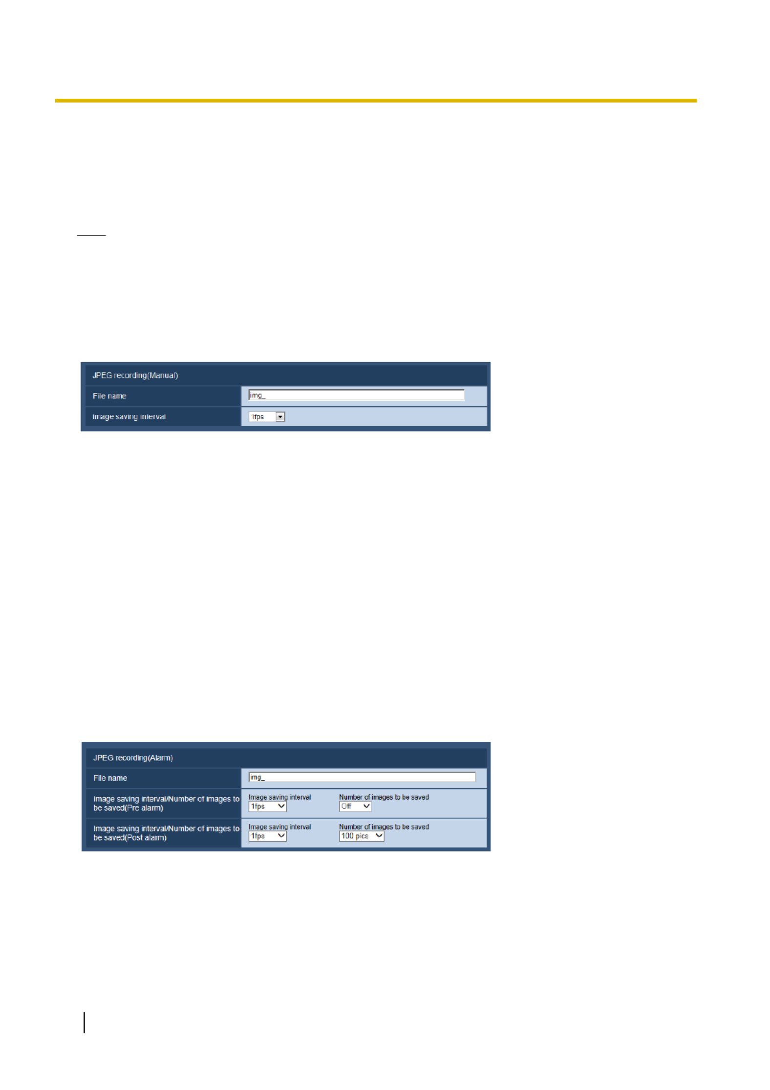
•Schedule: Saves images in accordance with the settings for “Schedule” ( page 184). Available only for®
the “H.264(1)”, “H.264(2)”, “H.264(3)”, or “H.264(4)” images.
•Default:
–Recording stream 1: FTP error
–Recording stream 2: Alarm input
Note
•When “H.264(1)”, “H.264(2)”, “H.264(3)”, or “H.264(4)” is selected for “Recording format”, “FTP
error” is unavailable.
•When “JPEG(1)”, “JPEG(2)”, or “JPEG(3)” is selected for “Recording format”, “Schedule” is
unavailable.
JPEG recording(Manual)
This setting is only available when “JPEG(1)”, “JPEG(2)”, or “JPEG(3)” is selected for “Recording format”, and
“Manual” is selected for “Save trigger”.
[File name]
Enter the file name used for the image to be saved on the SD memory card. The file name will be as follows.
•File name: [“Entered file name” + “Time and date (year/ month/ day/ hour/ minute/ second)”] + “Serial
number”
•Available number of characters: 1 - 8 characters
•Unavailable characters: " & * / : ; < > ? \ |
[Image saving interval]
When “Manual” is selected for “Save trigger”, select an interval (frame rate) of saving images on the SD memory
card from the following.
0.1fps/0.2fps/0.33fps/0.5fps/1fps
•Default: 1fps
JPEG recording(Alarm)
This setting is only available when “JPEG(1)”, “JPEG(2)”, or “JPEG(3)” is selected for “Recording format”, and
“Alarm input” is selected for “Save trigger”.
[File name]
Enter the file name used for the image to be saved on the SD memory card. The file name will be as follows.
•File name: [“Entered file name” + “Time and date (year/ month/ day/ hour/ minute/ second)”] + “Serial
number”
60 Operating Instructions
10 Configure the basic settings of the camera [Basic]

•Available number of characters: 1 - 8 characters
•Unavailable characters: " & * / : ; < > ? \ |
[Image saving interval/Number of images to be saved(Pre alarm)] - [Image saving interval]
When “Alarm input” is selected for “Save trigger”, select a pre alarm interval (frame rate) of saving images on
the SD memory card from the following.
0.1fps/0.2fps/0.33fps/0.5fps/1fps
•Default: 1fps
[Image saving interval/Number of images to be saved(Pre alarm)] - [Number of images to be
saved]
Select a number of pre alarm images to be saved on the SD memory card from the following.
Off/1pic/2pics/3pics/4pics/5pics
•Default: Off
[Image saving interval/Number of images to be saved(Post alarm)] - [Image saving interval]
When “Alarm input” or “Manual” is selected for “Save trigger”, select an interval (frame rate) of saving images
on the SD memory card from the following.
0.1fps/ 0.2fps/ 0.33fps/ 0.5fps/ 1fps
•Default: 1fps
[Image saving interval/Number of images to be saved(Post alarm)] - [Number of images to be
saved]
Select a number of alarm images to be saved on the SD memory card from the following.
10pics/ 20pics/ 30pics/ 50pics/ 100pics/ 200pics/ 300pics/ 500pics/ 1000pics/ 2000pics/ 3000pics
•Default: 100pics
H.264 recording(Alarm)
This setting is only available when “H.264(1)”, “H.264(2)”, “H.264(3)”, or “H.264(4)”, is selected for “Recording
format” of the SD memory card, and “Alarm input” is selected for “Save trigger”.
[Pre alarm (recording) duration]
Determine whether or not to perform the pre alarm recording. Set the duration to save image data on the SD
memory card.
Off/ 1s/ 2s/ 3s/ 4s/ 5s/ 8s/ 10s/ 15s/ 20s/ 25s/ 30s/ 40s/ 50s/ 60s/ 90s/ 120s
•Default: Off
Note
•The available values change depending on the H.264 bit rate selected for recording. As the selected
bit rate increases, the available maximum value for the pre alarm duration decreases.
[Post alarm (recording) duration]
Set the duration to save image data on the SD memory card after an alarm occurrence.
10s/ 20s/ 30s/ 40s/ 50s/ 60s/ 120s/ 180s/ 240s/ 300s
•Default: 30s
* The actual recording time may sometimes be longer than the duration selected for this setting.
Operating Instructions 61
10 Configure the basic settings of the camera [Basic]

SD memory card information
[Remaining capacity(Total)]
Total capacity and remaining capacity of the SD memory card will be displayed.
Depending on the status of the SD memory card, the size indications will differ as follows.
Indication Description
--------MB/--------MB No SD memory card is inserted. Failed to obtain available capacity
due to error, etc.
********MB/********MB The SD memory card is unformatted, or locked (write-protected).
########MB/########MB The password lock of the SD memory card cannot be removed.
Note
•When “Off” is selected for “Overwrite” and the available size of the SD memory card is “0 MB”, images
will not be saved on the SD memory card. When the notification function is on, a notification will be
sent to the registered addresses and destinations of the Panasonic alarm protocol when the SD
memory card becomes full. ( page 122, page 132)®
[Format]
To format the SD memory card, click the [Execute] button.
IMPORTANT
•Before formatting the SD memory card, it is necessary to select “Use” for “SD memory card” on the
[SD memory card] tab of the “Basic” page ( page 55) and “Off” for “FTP periodic image®
transmission” on the [Advanced] tab of the “Network” page ( page 155).®
•Use the SD memory card after formatting it using the [SD memory card] tab. If using the SD memory
card that has not been formatted on the [SD memory card] tab, the following functions may not work
correctly.
–Save/obtain images that failed to transmit to the FTP server using the FTP periodic image
transmission function
–Save/obtain alarm images
–Save/obtain images saved manually
–Save/obtain images in accordance with the schedule settings
–Save/obtain the alarm logs, the manual/schedule logs, the FTP error logs and the system logs
–Save/obtain images recorded using the SD memory recording function of Panasonic network disk
recorder
–Play/download images on the SD memory card
•When an SD memory card is formatted while another user is in operation, the operation will be
canceled.
•It is impossible to access the SD memory card during the process of formatting.
•All data saved on the SD memory card will be deleted when the SD memory card is formatted.
•Do not turn off the power of the camera during the process of formatting.
•After formatting the SD memory card, available size may be smaller than the total size since the default
directory is automatically created in the SD memory card.
•Compatible SD memory card miniSD and microSD cards cannot be used
Manufactured by Panasonic (SD speed class 4 or higher)
–SDXC memory card: 64 GB, 128GB
–SDHC memory card: 4 GB, 8 GB, 16 GB, 32 GB
–SD memory card: 2 GB
•Refer to our website (http://security.panasonic.com/pss/security/support/info.html) for latest
information about the compatible SD memory cards.
62 Operating Instructions
10 Configure the basic settings of the camera [Basic]

•When repeatedly recording images on an SD memory card using the auto overwrite function, make
sure to use an SD memory card with high reliability and durability.
•Use the SD memory card that complies with UHS-1(Ultra High Speed-1) in the case of SD Speed Class
10.
•Use an SD memory card formatted compliant with the SD memory card standard at the default.
SD memory card images
[Access img.]
Images on the SD memory card can be obtained. Click the [Execute] button. Refer to page 72 for how to
access images.
10.4 Configure the settings relating to alteration
detection [Alteration detection]
Selecting alteration detection enables detection using exclusive software when the data on the SD memory
card is altered.
Alteration detection supports video files (MP4 format) only.
Refer to page 64 for information on how to configure alteration detection.
For further information about exclusive software for alteration detection and how to use it, refer to our website
below.
http://security.panasonic.com/pss/security/support/info.html
[Additional info for detecting alteration]
Select whether or not to give information for alteration detection to video files (MP4 format) to be saved on the
SD memory card.
Note
•When the self-signed certificate or certificate (security certificate) issued by CA (Certificate Authority)
is not valid, “On” cannot be selected.
•When “JPEG(1)”, “JPEG(2)”, or “JPEG(3)” is selected for “Compression” of “Recording stream 1”,
“On” cannot be selected.
Operating Instructions 63
10 Configure the basic settings of the camera [Basic]

[CRT key generate]
CRT key (encryption key) used for alteration detection is generated. To generate the CRT key, click the
[Execute] button to display “CRT key generate” dialog box.
[Self-signed Certificate] - [Generate]
The camera itself generates the security certificate used for alteration detection. (Self-signed certificate)
To generate the self-signed certificate, click the [Execute] button to display the “Self-signed Certificate -
Generate” dialog box.
[Self-signed Certificate] - [Information]
Displays the information of the self-signed certificate.
When the [Confirm] button is clicked, the registered information of the self-signed certificate will be displayed
in the “Self-signed Certificate - Confirm” dialog box.
When the [Delete] button is clicked, the generated self-signed certificate will be deleted.
[Self-signed Certificate] - [Certificate download]
Downloads the self-signed certificate.
When implementing alteration detection of video data (MP4 files) on the SD memory card using exclusive
software, the downloaded certificate is used.
[CA Certificate] - [Generate Certificate Signing Request]
When using the security certificate issued by CA as the security certificate used for alteration detection, the
CSR (Certificate Signing Request) will be generated.
To generate the CSR, click the [Execute] button to display the “CA Certificate - Generate Certificate Signing
Request” dialog window.
[CA Certificate] - [Certificate install]
Installs the certificate (security certificate) issued by CA and displays the information of the installed certificate.
To install the certificate, click the [Browse...] button to display the [Open] dialog box, and select the file of the
certificate issued by CA, and click the [Execute] button.
If the certificate is already installed, the file name of the installed certificate will be displayed.
[CA Certificate] - [Information]
Displays the information of the certificate issued by CA.
When the [Confirm] button is clicked, the registered information of the installed certificate will be displayed in
the “CA Certificate - Confirm” dialog box. If the certificate is not installed, the content of the generated CSR
file will be displayed.
When the [Delete] button is clicked, the installed certificate will be deleted.
[CA Certificate] - [Certificate download]
Downloads the certificate issued by CA from the camera.
When implementing alteration detection of video data (MP4 files) on the SD memory card using exclusive
software, the downloaded certificate is used.
IMPORTANT
•Before deleting the valid certificate (security certificate), confirm that there is a backup file on the PC
or another media. The backup file will be required when installing the certificate again.
10.5 How to configure alteration detection settings
The settings relating to alteration detection that detects when data in the SD memory card is altered or edited
can be configured on this page.
64 Operating Instructions
10 Configure the basic settings of the camera [Basic]

The alteration detection settings will be configured in the following procedure.
Generation of the C key (encryption key)RT
Configuration of the additional info for detecting alteration
Application for the approval by CA
(Certi-ficate Authority) - Issue of the certifi-cate
Generation of CSR (Certificate Signing Request)
Installation of the certi-ficate
Generation of the self-signed certificate
When using the certi-ficate issued by CAWhen using the self-signed certificate
10.5.1 Generation of the CRT key (encryption key)
IMPORTANT
•When the self-signed certificate or certificate (security certificate) issued by CA is valid, it is impossible
to generate the CRT key.
•When the certificate (security certificate) issued by CA is used, the available key size varies depending
on the CA. Check the available key size in advance.
•To generate the CRT key, it may take about 2 minutes. Do not operate the web browser until the
generation of CRT key is complete. While the CRT key is being generated, the refresh interval and line
speed may be lower.
1. Click the [Execute] button of “CRT key generate”.
→The “CRT key generate” dialog box will be displayed.
Operating Instructions 65
10 Configure the basic settings of the camera [Basic]

2. Enter the information of the certificate to be generated.
Item Description Available number of characters
[Common Name] Enter the camera address or host name. 64 characters
[Country] Enter the country name. (Omission is OK.) 2 characters (Country code)
[State] Enter the state name. (Omission is OK.) 128 characters
[Locality] Enter the locality name. (Omission is OK.) 128 characters
[Organization] Enter the organization name. (Omission is OK.) 64 characters
[Organizational
Unit]
Enter the unit name of the organization.
(Omission is OK.)
64 characters
[CRT key] Displays the key size and generation time & date
of the current key.
Note
•The available characters for [Common Name], [State], [Locality], [Organization], [Organizational
Unit] are 0-9, A-Z, a-z and the following marks.
- . _ , + / ( )
•When entering the IPv6 address for “Common Name”, put the address in brackets [ ].
Example: [2001:db8::10]
3. Click the [OK] button after entering the items.
→The self-signed certificate will be generated.
Note
•The information of the generated self-signed certificate will be displayed on “Self-signed
Certificate” - “Information”.
Depending on the status of the self-signed certificate, the following are displayed.
Indication Description
Not generated The self-signed certificate are not generated.
Invalid (Reason: CA Certificate installed) The self-signed certificate has already been
generated, and the certificate issued by CA has
been installed.
•In this case, the server certificate is validated.
Common name of the self-signed
certificate
The self-signed certificate has already been
generated and validated.
Operating Instructions 67
10 Configure the basic settings of the camera [Basic]

•When the [Confirm] button is clicked, the registered information of the self-signed certificate
(security certificate) will be displayed in the “Self-signed Certificate - Confirm” dialog box.
•When the [Delete] button is clicked, the generated self-signed certificate (security certificate) will
be deleted.
•When “On” is selected for “Additional info for detecting alteration”, it is impossible to delete the
self-signed certificate.
10.5.3 Generation of CSR (Certificate Signing Request)
IMPORTANT
•If the CRT key is not generated, it is impossible to generate the CSR.
•Before generating the CSR file, configure the following settings on [Internet Options] of the web browser
in advance. Click [Internet Options...] under [Tools] of the menu bar of Internet Explorer, and then click
the [Security] tab.
–Register the camera for [Trusted Sites].
–Click the [Custom level...] button to open the [Security Settings] window, and check the [Enable]
radio button of [File Download] under [Downloads].
–Click the [Custom level...] button to open the [Security Settings] window, and check the [Enable]
radio button of [Automatic prompting for file downloads] under [Downloads].
68 Operating Instructions
10 Configure the basic settings of the camera [Basic]
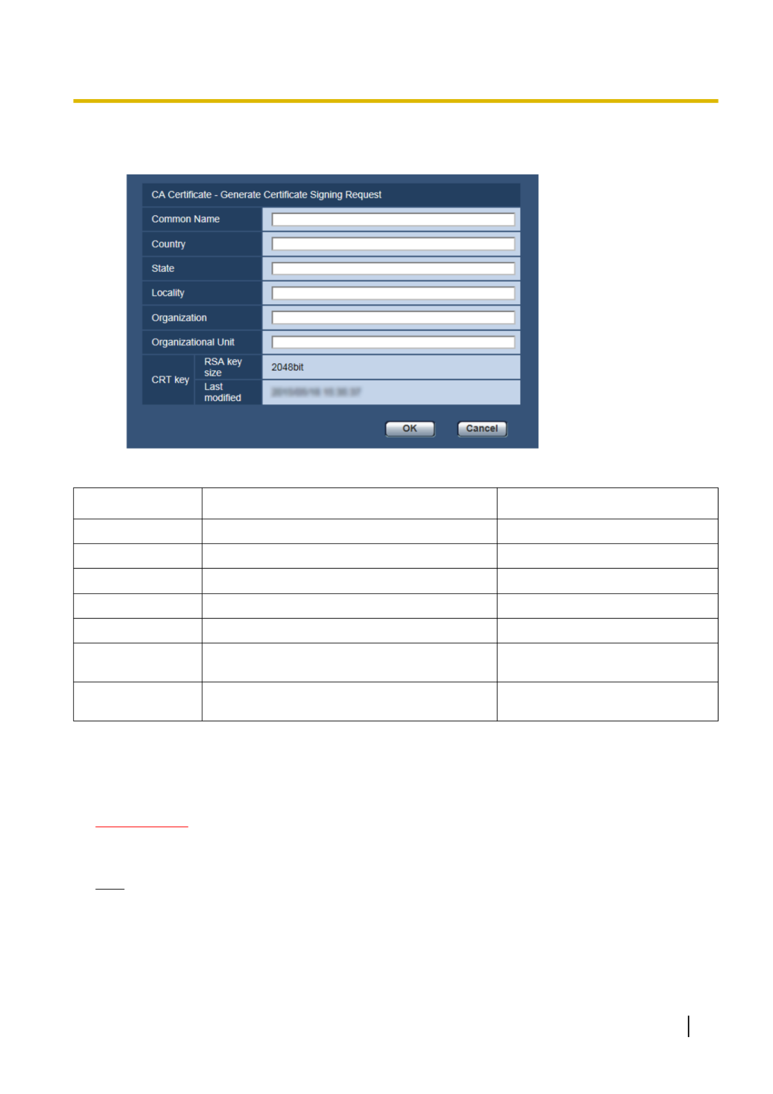
1. Click the [Execute] button of “CA Certificate - Generate Certificate Signing Request”.
→The “CA Certificate - Generate Certificate Signing Request” dialog box will be displayed.
2. Enter the information of the certificate to be generated.
Item Description Available number of characters
[Common Name] Enter the camera address or host name. 64 characters
[Country] Enter the country name. 2 characters (Country code)
[State] Enter the state name. 128 characters
[Locality] Enter the locality name. 128 characters
[Organization] Enter the organization name. 64 characters
[Organizational
Unit]
Enter the unit name of the organization. 64 characters
[CRT key] Displays the key size and generation time & date
of the current key.
3. Click the [OK] button after entering the items.
→The [Save As] dialog box will be displayed.
4. Enter a file name for the CSR in the [Save As] dialog box to save on the PC.
→The saved CSR file will be applied to the CA.
IMPORTANT
•The certificate will be issued for the set of the generated CSR and CRT key. If the CRT key is
re-generated or updated after applying to the CA, the issued certificate will be invalidated.
Note
•This camera generates the CSR file in the PEM format.
Operating Instructions 69
10 Configure the basic settings of the camera [Basic]

10.5.4 Installation of the certificate issued by CA
IMPORTANT
•If the CSR file is not generated, it is impossible to install the certificate (security certificate) issued by
CA.
•For the installation, the certificate issued by CA is required.
1. Click the [Browse...] button of “CA Certificate - Certificate install”.
→The [Open] dialog box will be displayed.
2. Select the certification file and click the [Open] button. Then, click the [Execute] button.
→The certification will be installed.
Note
•The host name registered in the installed certificate will be displayed on “CA Certificate -
Information”. Depending on the status of the certificate, the following are displayed.
Indication Description
Invalid The server certification is not installed.
[Host name of the certificate] The certificate has already been installed and
validated.
Expired The certification has already expired.
•When the [Confirm] button is clicked, the registered information of the installed certificate will be
displayed in the “CA Certificate - Confirm” dialog box. (Only “Organizational Unit” will be displayed
with an asterisk (*).)
•When the [Delete] button is clicked, the installed server certificate will be deleted.
•When “On” is selected for “Additional info for detecting alteration”, it is impossible to delete the
certificate issued by CA.
•To change (or update) the certificate issued by CA, perform step 1 and 2.
IMPORTANT
•Before deleting the valid certificate (security certificate), confirm that there is a backup file on the PC
or another media. The backup file will be required when installing the certificate again.
•The expiration date of the certificate issued by CA can be checked by double-clicking the server
certification file issued by CA.
70 Operating Instructions
10 Configure the basic settings of the camera [Basic]

10.5.5 Configuration of alteration detection
1. Select “On” for “Additional info for detecting alteration”, and click the [Set] button.
2. Extensive information for alteration detection will be added to video files (MP4 format) recorded after
changing the setting.
IMPORTANT
•When the “Additional info for detecting alteration” setting is changed, manual recording on the SD
memory card will stop. Start manual saving again as necessary.
Note
•Alteration detection can be performed on video files (MP4 format) recorded when “On” is selected for
“Additional info for detecting alteration” using exclusive software.
For further information about exclusive software and how to use it, refer to our website below.
http://security.panasonic.com/pss/security/support/info.html
Operating Instructions 71
10 Configure the basic settings of the camera [Basic]

10.6 Access copy images saved on the SD memory
card onto the PC [SD memory card images]
Click the [SD memory card] tab on the “Basic” page. ( page 42, page 44)®
The following are descriptions of how to copy images saved on the SD memory card onto the PC. It is necessary
in advance to select “Allow” for “FTP access to camera” on the [Network] tab of the “Network” page.
( page 145)®
IMPORTANT
•It may sometimes be impossible to operate when another user is accessing images on the SD memory
card. In this case, retry later.
•Depending on the settings of a proxy server or a firewall, images may not be obtained via a network.
In this case, refer to the network administrator.
1. Click the [Execute] button.
→The user authentication window will be displayed.
2. Click the [OK] button after entering the user name and password of the camera administrator.
→The folder in which images are to be saved will be displayed.
Note
•When the FTP server of the camera is logged to access images, the SD memory card is assigned to
Drive B.
Images are saved in different directories according to “Save trigger”.
Move to the directory corresponding to the desired images and copy them.
Refer to page 221 for further information about the directory structure.
72 Operating Instructions
10 Configure the basic settings of the camera [Basic]

Possible number of JPEG images that can be saved on the SD memory card
(as indications)
For possible number of JPEG images that can be saved on the SD memory card, refer to our website below.
http://security.panasonic.com/pss/security/support/info.html
Possible duration of H.264 images that can be saved on the SD memory card
(as indications)
For possible duration of H.264 images that can be saved on the SD memory card, refer to our website below.
http://security.panasonic.com/pss/security/support/info.html
Operating Instructions 73
10 Configure the basic settings of the camera [Basic]

Note
•Schedule saving is available only when “H.264(1)”, “H.264(2)”, “H.264(3)”, or “H.264(4)” is selected for
“Recording format”.
FTP error
The settings related to the directory name of the PC that recorded images of when FTP errors occur will be
downloaded to can be performed.
Designate the destination folder in the same manner as for “Alarm”.
IMPORTANT
•When “Name w/o time&date” is selected for “File name” of “FTP periodic image transmission”on the
[Advanced] tab on the “Network” page, FTP error log and associated images will not be saved. To save
them, select “Name w/time&date”. ( page 153)®
Note
•When “H.264(1)”, “H.264(2)”, “H.264(3)”, or “H.264(4)” is selected for “Recording format”, “FTP
error” is unavailable.
[Permission level of viewing logs]
User level settings for viewing and operating “Log” on the “Live” page can be configured.
1. Level 1 only: only Level 1 users can view and operate the “Log”.
2. Level 2 or higher: only Level 1 and Level 2 users can view and operate the “Log”.
3. All users: all users can view and operate the “Log”. However, only Level 1 and Level 2 users can delete
logs, and only Level 1 users can view SD memory card folders.
Default: 1. Level 1 only
Operating Instructions 75
10 Configure the basic settings of the camera [Basic]

11 Configure the settings relating to images and
audio [Image/Audio]
The settings relating to JPEG and H.264 images such as the settings of image quality, audio, etc. can be
configured on this page.
The “Image/Audio” page has the [JPEG/H.264] tab, the [Image quality] tab, and the [Audio] tab.
11.1 Configure the settings relating to the image
capture mode [JPEG/H.264]
Click the [JPEG/H.264] tab on the “Image/Audio” page. ( page 42, page 44)®
[Image capture mode]
Select an image capture mode from the following.
SFx311
SFx310
SPN311
SPN310
SPW311L
1.3 mega pixel [16:9](30fps mode)/1.3 mega pixel [16:9](60fps mode)/1.3 mega pixel [4:3](30fps mode)/2 mega
pixel [16:9](30fps mode)
SPW312L
1.3 mega pixel [16:9](30fps mode)/1.3 mega pixel [4:3](30fps mode)/2 mega pixel [16:9](30fps mode)
•Default: 1.3 mega pixel [16:9](30fps mode)
SPN531
SPW531L
2 mega pixel [16:9](30fps mode)/2 mega pixel [16:9](60fps mode)/2 mega pixel [4:3](30fps mode)/3 mega pixel
[4:3](30fps mode)*
SPW532L
2 mega pixel [16:9](30fps mode)/2 mega pixel [4:3](30fps mode)/3 mega pixel [4:3](30fps mode)*
*Used by super resolution techniques.
•Default: 2 mega pixel [16:9](30fps mode)
IMPORTANT
•The positions of areas may move out of alignment when the “Image capture mode” setting is changed
when the following area settings are configured. Therefore we recommend that you configure each
area setting after configuring the “Image capture mode”.
–mask area ( page 96)®
–privacy zone ( page 103)®
–VMD area ( page 126)®
–VIQS area ( page 105)®
–Cropping outlines ( page 137)®
Note
•When “On” is selected for “VIQS” and the setting value for the aspect ratio is changed from “4:3” to
“16:9”, make sure that the VIQS setting value does not exceed the maximum designated range.
76 Operating Instructions
11 Configure the settings relating to images and audio [Image/Audio]

[Image capture size]
Select the image capture size to display the JPEG image.
SFx311
SFx310
SPN311
SPN310
SPW311L
SPW312L
–When “1.3 mega pixel [16:9](30fps mode)” or “1.3 mega pixel [16:9](60fps mode)” is selected
for“Image capture mode”
1280x720/640x360/320x180/160x90
–When “1.3 mega pixel [4:3](30fps mode)” is selected for “Image capture mode”
1280x960/800x600/VGA/400x300/QVGA/160x120
–When “2 mega pixel [16:9](30fps mode)” is selected for “Image capture mode”
1920x1080/640x360/320x180/160x90
•Default:
–JPEG(1): 1280x720
–JPEG(2): 640x360
–JPEG(3): 320x180
SPN531
SPW531L
SPW532L
–When “2 mega pixel [16:9](30fps mode)” or “2 mega pixel [16:9](60fps mode)” is selected for “Image
capture mode”
1920x1080/1280x720/640x360/320x180/160x90
–When “2 mega pixel [4:3](30fps mode)” is selected for “Image capture mode”
1600x1200/1280x960/800x600/VGA/400x300/QVGA/160x120
–When “3 mega pixel [4:3](30fps mode)” is selected for “Image capture mode”
2048x1536/1280x960/800x600/VGA/400x300/QVGA/160x120
•Default:
–JPEG(1): 1920x1080
–JPEG(2): 640x360
–JPEG(3): 320x180
[Image quality]
Select two types of image quality of JPEG images for each image capture size.
0 Super fine/ 1 Fine/ 2/ 3/ 4/ 5 Normal/ 6/ 7/ 8/ 9 Low
•Default:
–Quality1: 5 Normal
–Quality2: 8
The setting for “Quality1” is activated for FTP periodic image transmission, files attached to alarm E-mails and
SD memory recording.
78 Operating Instructions
11 Configure the settings relating to images and audio [Image/Audio]

11.3 Configure the settings relating to H.264 images
[JPEG/H.264]
Click the [JPEG/H.264] tab on the “Image/Audio” page. ( page 42, page 44)®
Configure the settings relating to H.264 image such as “Max bit rate (per client)”, “Image capture size”, “Image
quality”, etc. in this section. Refer to page 77 for the settings relating to JPEG images.
1920x1080
4096 *kbps
Smart Coding mode
H.264(1)/H.264(2)/H.264(3)/H.264(4)
[H.264 transmission]
Select “On” or “Off” to determine whether or not to transmit H.264 images.
•On: Transmits H.264 images.
•Off: Does not transmit H.264 images.
•Default: On
Note
•When “On” is selected for “H.264 transmission” in “H.264(1)”, “H.264(2)”, “H.264(3)”, or “H.264(4)”
displaying of H.264 images or JPEG images on the “Live” page will become available.
•When “On” is selected for “H.264 transmission” in “H.264(1)”, “H.264(2)”, “H.264(3)”, or “H.264(4)”, the
transmission interval of JPEG images may sometimes become longer.
[Internet mode (over HTTP)]
Select “On” when transmitting H.264 images via the Internet. It is possible to transmit H.264 images without
changing the broadband router settings configured for JPEG image transmission.
•On: H.264 images and audio will be transmitted using the HTTP port. Refer to page 147 for further
information about the HTTP port number settings.
Operating Instructions 79
11 Configure the settings relating to images and audio [Image/Audio]

•Off: H.264 images and audio will be transmitted using the UDP port.
•Default: Off
Note
•When “On” is selected, only “Unicast port (AUTO)” will be available for “Transmission type”.
•When “On” is selected, it may take time to start displaying H.264 images.
•When “On” is selected, H.264 images may not be displayed depending on the number of the concurrent
access user and audio data availability, etc.
•When “On” is selected, only IPv4 access is available.
[Image capture size]
Select the image capture size from the following. What can be selected may be limited depending on the image
capture size already selected.
Image capture
mode
Image capture size
H.264(1) H.264(2) H.264(3) H.264(4)
1.3 mega pixel [16:9]
(30fps mode)
1280x720
640x360
320x180
160x90
1280x720
640x360
320x180
160x90
1280x720
640x360
320x180
160x90
1280x720
640x360
320x180
160x90
1.3 mega pixel [16:9]
(60fps mode)
1280x720 1280x720
640x360
320x180
160x90
1280x720
640x360
320x180
160x90
1280x720
640x360
320x180
160x90
1.3 mega pixel [4:3]
(30fps mode)
1280x960
800x600
VGA
400x300
QVGA
160x120
1280x960
800x600
VGA
400x300
QVGA
160x120
1280x960
800x600
VGA
400x300
QVGA
160x120
1280x960
800x600
VGA
400x300
QVGA
160x120
2 mega pixel [16:9]
(30fps mode)
SFV311
1920x1080
640x360
320x180
160x90
1920x1080
640x360
320x180
160x90
640x360
320x180
160x90
640x360
320x180
160x90
2 mega pixel [16:9]
(30fps mode)
SPN531
SPW531L
SPW532L
1920x1080
1280x720
640x360
320x180
160x90
1920x1080
1280x720
640x360
320x180
160x90
1280x720
640x360
320x180
160x90
1280x720
640x360
320x180
160x90
2 mega pixel [16:9]
(60fps mode)
1920x1080
1280x720
1920x1080
1280x720
640x360
320x180
160x90
1280x720
640x360
320x180
160x90
1280x720
640x360
320x180
160x90
80 Operating Instructions
11 Configure the settings relating to images and audio [Image/Audio]

Image capture
mode
Image capture size
H.264(1) H.264(2) H.264(3) H.264(4)
2 mega pixel [4:3]
(30fps mode)
1600x1200
1280x960
800x600
VGA
400x300
QVGA
160x120
1600x1200
1280x960
800x600
VGA
400x300
QVGA
160x120
1280x960
800x600
VGA
400x300
QVGA
160x120
1280x960
800x600
VGA
400x300
QVGA
160x120
3 mega pixel [4:3]
(30fps mode)
2048x1536
1280x960
800x600
VGA
400x300
QVGA
160x120
2048x1536
1280x960
800x600
VGA
400x300
QVGA
160x120
1280x960
800x600
VGA
400x300
QVGA
160x120
1280x960
800x600
VGA
400x300
QVGA
160x120
•Default:
SFV311
–H.264(1): 1280x720
–H.264(2): 640x360
–H.264(3): 320x180
–H.264(4): 160x90
SPN531
SPW531L
SPW532L
–H.264(1): 1920x1080
–H.264(2): 640x360
–H.264(3): 320x180
–H.264(4): 160x90
Note
•The “Image capture mode” that can be selected differs depending on the model. Please read
page 76 regarding image capture mode settings.
[Transmission priority]
Select a transmission priority for H.264 images from the following.
•Constant bit rate: H.264 images will be transmitted with the bit rate selected for “Max bit rate (per
client) *”.
•VBR: H.264 images will be transmitted with the frame rate selected for “Frame rate*” while maintaining the
image quality level selected in “Image quality”. H.264 images will be transmitted with the bit rate kept within
the maximum bit rate that is set for “Max bit rate (per client)*”. The image quality is fixed, and the recording
capacity changes according to the “Image quality” setting and conditions of the subject. When calculation
of recording capacity is needed in advance, use “Advanced VBR”.
•Frame rate: H.264 images will be transmitted with the frame rate selected for “Frame rate*”.
•Best effort: In accordance with the network bandwidth, H.264 images will be transmitted with the bit rate
varying between the maximum and minimum bit rates that are set for “Max bit rate (per client)*”.
•Advanced VBR: H.264 images are transmitted at the frame rate specified for “Frame rate*” while the image
quality is controlled so that the average transmission rate during the period specified for “Control time
period” becomes the bit rate selected for “Max bit rate (per client)*”.
•Default: Frame rate
Operating Instructions 81
11 Configure the settings relating to images and audio [Image/Audio]

Note
•When “Frame rate” or “Advanced VBR” is selected for “Transmission priority”, number of users who
can access the camera may be limited more (may become less than 10).
[Frame rate*]
Select a frame rate for H.264 images from the following.
1fps/ 3fps/ 5fps*/ 7.5fps*/ 10fps*/ 12fps*/ 15fps*/ 20fps*/ 30fps*/60fps*
•Default: 30fps*
Note
•When “Frame rate”, “Advanced VBR”, or “VBR” is selected for “Transmission priority”, this setting is
available.
•“Frame rate*” is restricted by “Max bit rate (per client)*”. For this reason, the frame rate may be lower
than the specified value when any value marked with an asterisk (*) is selected. When “VBR” is selected
for “Transmission priority”, depending on the settings of “Max bit rate (per client)*” and “Image
quality”, transmission of images may periodically be paused. Check the transmission of images after
changing settings.
•H.264(1) will be fixed to 60fps when “2 mega pixel [16:9](60fps mode)” or “1.3 mega pixel [16:9](60fps
mode)” is selected for “Image capture mode”.
[Burst tolerance level]
Select how much the bit rate can exceed “Max bit rate (per client)*” by from the following.
High/Middle/Low
•Default: Low
Note
•This setting is only available when “Advanced VBR” is selected for “Transmission priority”.
[Control time period]
Select the time period that the bit rate will be controlled for from the following. Images are transmitted so that
the average transmission rate during the selected period becomes the bit rate selected for “Max bit rate (per
client)*”.
1h/6h/24h/1week
•Default: 24h
Note
•This setting is only available when “Advanced VBR” is selected for “Transmission priority”.
[Max bit rate (per client)*]
Select a H.264 bit rate per a client from the following. When “Best effort” is selected for “Transmission
priority”, set the maximum and minimum bit rates.
64kbps/ 128kbps*/ 256kbps*/ 384kbps*/ 512kbps*/ 768kbps*/ 1024kbps*/ 1536kbps*/ 2048kbps*/ 3072kbps*/
4096kbps*/ 6144kbps*/ 8192kbps*/ 10240kbps*/ 12288kbps*/ 14336kbps*/ 16384kbps*/ 20480kbps*/
24576kbps*/ 30720kbps*/ 40960kbps*
•Default:
–H.264(1): 4096kbps*
SPN531
SPW531L
SPW532L
–H.264(1): 2048kbps*
SFV311
–H.264(2): 1536kbps*
–H.264(3): 1024kbps*
–H.264(4): 512kbps*
* The range of bit rates that can be configured for H.264 bit rates differs depending on the “Transmission
priority” and “Image capture size”.
82 Operating Instructions
11 Configure the settings relating to images and audio [Image/Audio]

When “Constant bit rate”, “Frame rate”, “Advanced VBR”, or “Best effort” is selected for “Transmission
priority”
•160x120 and 160x90: 64kbps - 2048kbps*
•QVGA, 400x300, VGA, 320x180, and 640x360: 64kbps - 4096kbps*
•800x600: 128kbps* - 4096kbps*
•1280x960 and 1280x720: 256kbps* - 8192kbps*
•1920x1080 and 1600x1200: 512kbps* - 14336kbps*
•1920x1080 (60fps) and 1280x720 (60fps): 1024kbps* - 24576kbps*
•2048x1536: 1024kbps* - 24576kbps*
When “VBR” is selected for “Transmission priority”
•160x120 and 160x90: 64kbps - 40960kbps*
•QVGA, 400x300, VGA, 320x180, and 640x360: 64kbps - 40960kbps*
•800x600: 128kbps* - 40960kbps*
•1280x960 and 1280x720: 256kbps* - 40960kbps*
•1920x1080 and 1600x1200: 512kbps* - 40960kbps*
•1920x1080 (60fps) and 1280x720 (60fps): 1024kbps* - 40960kbps*
•2048x1536: 1024kbps* - 40960kbps*
Note
•The H.264 bit rate is restricted by “Bandwidth control(bit rate)” on the [Network] tab on the “Network”
page ( page 145). For this reason, the bit rate may be lower than the value when any value with an®
asterisk (*) on the right is selected.
[Image quality]
Select the image quality of H.264 images from the following.
•When “Transmission priority” is set to “Constant bit rate” or “Best effort”: Low(Motion priority)/
Normal/ Fine(Image quality priority)
•VBR: 0 Super fine/ 1 Fine/ 2/ 3/ 4/ 5 Normal/ 6/ 7/ 8/ 9 Low
•Default: Normal
Note
•When “Constant bit rate”, “Best effort”, or “VBR” is selected for “Transmission priority”, this setting is
available.
[Smart Coding mode]
Select the adjusting method of stream transmissions from the following.
A smaller amount of data can be transmitted during video with little movement.
On/Off
•Default: Off
Note
•Can be set only when “Transmission priority” is set to “VBR”.
•When “Smart Coding mode” is set to “On”, refresh interval is fixed at 8s.
•When switching the “Smart Coding mode” setting from “On” to “Off”, the “Refresh interval” setting will
return to the “Off” settings.
•Turning Smart Coding mode to “On” will make refresh interval variable between 1s and 8s. If only
I-frame is used for playback and display, the display interval will change.
[Refresh interval]
Select an interval (I-frame interval; 0.2 - 5 seconds) to refresh the displayed H.264 images.
If using under a network environment with frequent error occurrences, shorten the refresh interval for H.264
to diminish image distortions. However, the refresh interval may be longer than the set value.
Operating Instructions 83
11 Configure the settings relating to images and audio [Image/Audio]

•Default: 37004
Note
•When audio is transmitted from the unit, the port number to be used will be the multicast port number
plus “1000”.
[Multicast TTL/HOPLimit] *2
Enter a value for “Multicast TTL/HOPLimit”.
•Available value: 1-254
•Default: 16
IMPORTANT
•When transmitting an H.264 image via a network, the transmitted image sometimes may not be
displayed depending on the settings of a proxy server or a firewall. In this case, refer to the network
administrator.
•When two or more network interface cards are installed on the PC in use, the network interface
card(s) not used for receiving images should be invalidated when displaying images using the multicast
port.
*1 It is necessary to designate the unicast port number when “Unicast port (MANUAL)” is selected for “Transmission type”.
*2 It is necessary to designate the multicast IP address when “Multicast” is selected for “Transmission type”.
Operating Instructions 85
11 Configure the settings relating to images and audio [Image/Audio]

11.4 Configure the settings relating to image adjust,
focus, back focus, extra optical zoom, privacy zone,
VIQS, and lens distortion compensation [Image
quality]
Click the [Image quality] tab on the “Image/Audio” page. ( page 42, page 44)®
When the [Setup>>] button of each setting item is clicked, the detailed settings menu will be displayed in a
newly opened window. The detailed settings can be configured while monitoring images displayed on the
[Image quality] tab.
The settings relating to image adjust, focus, extra optical zoom, privacy zone, VIQS, and lens distortion
compensation can be configured in this section.
Focus
[Image adjust]
Click the [Setup>>] button to display the setup menu that can configure the settings relating to image quality.
The setup menu will be displayed in a newly opened window. ( page 87)®
[Focus]
SFx311
SFx310
SPW311L
SPW312L
SPW531L
SPW532L
Click the [Setup>>] button to display the setup menu that can configure the settings relating to the focus. The
setup menu will be displayed in a newly opened window. ( page 99)®
[Back focus]
SPN311
SPN531
Click the [Setup>>] button to display the setup menu that can configure the settings relating to the back focus.
The setup menu will be displayed in a newly opened window. ( page 100)®
[Extra optical zoom]
Click the [Setup>>] button to display the setup menu that can configure the extra optical zoom. The setup menu
will be displayed in a newly opened window. ( page 101)®
86 Operating Instructions
11 Configure the settings relating to images and audio [Image/Audio]
Produktspezifikationen
| Marke: | Panasonic |
| Kategorie: | Überwachungskamera |
| Modell: | WV-SPW311A |
Brauchst du Hilfe?
Wenn Sie Hilfe mit Panasonic WV-SPW311A benötigen, stellen Sie unten eine Frage und andere Benutzer werden Ihnen antworten
Bedienungsanleitung Überwachungskamera Panasonic

2 Oktober 2024
10 September 2024
9 September 2024
28 August 2024
20 August 2024
3 August 2024
1 August 2024
29 Juli 2024
25 Juli 2024
24 Juli 2024
Bedienungsanleitung Überwachungskamera
- Überwachungskamera Samsung
- Überwachungskamera Approx
- Überwachungskamera Belkin
- Überwachungskamera Sanyo
- Überwachungskamera Exibel
- Überwachungskamera Gembird
- Überwachungskamera Genius
- Überwachungskamera Hama
- Überwachungskamera LogiLink
- Überwachungskamera Logitech
- Überwachungskamera Manhattan
- Überwachungskamera Nedis
- Überwachungskamera Niceboy
- Überwachungskamera Philips
- Überwachungskamera Sony
- Überwachungskamera Trust
- Überwachungskamera Clas Ohlson
- Überwachungskamera Profile
- Überwachungskamera ZyXEL
- Überwachungskamera Bosch
- Überwachungskamera Laserliner
- Überwachungskamera Buffalo
- Überwachungskamera Canon
- Überwachungskamera Velleman
- Überwachungskamera Powerfix
- Überwachungskamera Eminent
- Überwachungskamera Linksys
- Überwachungskamera Maginon
- Überwachungskamera Netgear
- Überwachungskamera Technaxx
- Überwachungskamera Alecto
- Überwachungskamera Denver
- Überwachungskamera EMOS
- Überwachungskamera Gira
- Überwachungskamera König
- Überwachungskamera MarQuant
- Überwachungskamera Renkforce
- Überwachungskamera Thomson
- Überwachungskamera Trevi
- Überwachungskamera Blaupunkt
- Überwachungskamera Schneider
- Überwachungskamera Trebs
- Überwachungskamera Pyle
- Überwachungskamera Topcom
- Überwachungskamera Pioneer
- Überwachungskamera JVC
- Überwachungskamera Motorola
- Überwachungskamera Xiaomi
- Überwachungskamera Abus
- Überwachungskamera Avidsen
- Überwachungskamera Elro
- Überwachungskamera EZVIZ
- Überwachungskamera Imou
- Überwachungskamera INSTAR
- Überwachungskamera Megasat
- Überwachungskamera Olympia
- Überwachungskamera Smartwares
- Überwachungskamera Switel
- Überwachungskamera Yale
- Überwachungskamera Ferguson
- Überwachungskamera Orion
- Überwachungskamera Gigaset
- Überwachungskamera Strong
- Überwachungskamera Toshiba
- Überwachungskamera Garmin
- Überwachungskamera Perel
- Überwachungskamera Netis
- Überwachungskamera Lindy
- Überwachungskamera Fenton
- Überwachungskamera Waeco
- Überwachungskamera Acme
- Überwachungskamera Burg Wächter
- Überwachungskamera Marmitek
- Überwachungskamera Marshall
- Überwachungskamera Honeywell
- Überwachungskamera B/R/K
- Überwachungskamera Marshall Electronics
- Überwachungskamera TRENDnet
- Überwachungskamera Targa
- Überwachungskamera First Alert
- Überwachungskamera AVerMedia
- Überwachungskamera Zebra
- Überwachungskamera TP-Link
- Überwachungskamera Flamingo
- Überwachungskamera Kodak
- Überwachungskamera Rollei
- Überwachungskamera IGet
- Überwachungskamera Adj
- Überwachungskamera Netatmo
- Überwachungskamera Duramaxx
- Überwachungskamera Ebode
- Überwachungskamera Xavax
- Überwachungskamera InFocus
- Überwachungskamera Overmax
- Überwachungskamera Monoprice
- Überwachungskamera Monacor
- Überwachungskamera JUNG
- Überwachungskamera Ednet
- Überwachungskamera AG Neovo
- Überwachungskamera Nest
- Überwachungskamera Edimax
- Überwachungskamera V-TAC
- Überwachungskamera Aritech
- Überwachungskamera Uniden
- Überwachungskamera Kogan
- Überwachungskamera Genie
- Überwachungskamera M-e
- Überwachungskamera Elmo
- Überwachungskamera Lumens
- Überwachungskamera Jablocom
- Überwachungskamera Conceptronic
- Überwachungskamera D-Link
- Überwachungskamera Eufy
- Überwachungskamera Stabo
- Überwachungskamera Friedland
- Überwachungskamera EVOLVEO
- Überwachungskamera SPC
- Überwachungskamera August
- Überwachungskamera Ring
- Überwachungskamera Digitus
- Überwachungskamera SereneLife
- Überwachungskamera Swann
- Überwachungskamera Vitek
- Überwachungskamera DataVideo
- Überwachungskamera LevelOne
- Überwachungskamera Aida
- Überwachungskamera APC
- Überwachungskamera Beafon
- Überwachungskamera Chuango
- Überwachungskamera Cisco
- Überwachungskamera Grandstream
- Überwachungskamera Delta Dore
- Überwachungskamera EVE
- Überwachungskamera Defender
- Überwachungskamera Tenda
- Überwachungskamera Swisstone
- Überwachungskamera Foscam
- Überwachungskamera Ubiquiti Networks
- Überwachungskamera Kramer
- Überwachungskamera Vaddio
- Überwachungskamera Intellinet
- Überwachungskamera Reolink
- Überwachungskamera Swan
- Überwachungskamera Hikvision
- Überwachungskamera FLIR
- Überwachungskamera Furrion
- Überwachungskamera Arlo
- Überwachungskamera Nexxt
- Überwachungskamera Planet
- Überwachungskamera EnGenius
- Überwachungskamera Dörr
- Überwachungskamera Lorex
- Überwachungskamera Ikan
- Überwachungskamera Comtrend
- Überwachungskamera Somfy
- Überwachungskamera Dahua
- Überwachungskamera Dedicated Micros
- Überwachungskamera DIO
- Überwachungskamera EasyN
- Überwachungskamera Escam
- Überwachungskamera EverFocus
- Überwachungskamera Ganz
- Überwachungskamera GeoVision
- Überwachungskamera Hombli
- Überwachungskamera Home Protector
- Überwachungskamera Iiquu
- Überwachungskamera Indexa
- Überwachungskamera Interlogix
- Überwachungskamera KlikaanKlikuit
- Überwachungskamera Kompernass
- Überwachungskamera Mr Safe
- Überwachungskamera Naxa
- Überwachungskamera Nordval
- Überwachungskamera Notifier
- Überwachungskamera Oplink
- Überwachungskamera Provision ISR
- Überwachungskamera Quantum
- Überwachungskamera Raymarine
- Überwachungskamera Revo
- Überwachungskamera SAB
- Überwachungskamera Satel
- Überwachungskamera SecurityMan
- Überwachungskamera Sinji
- Überwachungskamera SMC
- Überwachungskamera Sonic Alert
- Überwachungskamera Sricam
- Überwachungskamera Steren
- Überwachungskamera Storage Options
- Überwachungskamera Tenvis
- Überwachungskamera Hive
- Überwachungskamera Ubiquiti
- Überwachungskamera Vivotek
- Überwachungskamera Woonveilig
- Überwachungskamera Y-cam
- Überwachungskamera ACTi
- Überwachungskamera AVer
- Überwachungskamera Epcom
- Überwachungskamera ZKTeco
- Überwachungskamera AirLive
- Überwachungskamera Mobotix
- Überwachungskamera Dahua Technology
- Überwachungskamera Speco Technologies
- Überwachungskamera 3xLOGIC
- Überwachungskamera Atlantis Land
- Überwachungskamera CRUX
- Überwachungskamera Pentatech
- Überwachungskamera Summer Infant
- Überwachungskamera Illustra
- Überwachungskamera Surveon
- Überwachungskamera Avigilon
- Überwachungskamera Brilliant
- Überwachungskamera Hanwha
- Überwachungskamera Lanberg
- Überwachungskamera Verint
- Überwachungskamera Axis
- Überwachungskamera EtiamPro
- Überwachungskamera MEE Audio
- Überwachungskamera Advantech
- Überwachungskamera Chacon
- Überwachungskamera Alula
- Überwachungskamera EKO
- Überwachungskamera IOIO
- Überwachungskamera KJB Security Products
- Überwachungskamera BZBGear
- Überwachungskamera Adesso
- Überwachungskamera Brickcom
- Überwachungskamera Insteon
- Überwachungskamera Aigis
- Überwachungskamera Pelco
- Überwachungskamera ORNO
- Überwachungskamera Atlona
- Überwachungskamera Linear PRO Access
- Überwachungskamera Laxihub
- Überwachungskamera Valueline
- Überwachungskamera Aqara
- Überwachungskamera Tecno
- Überwachungskamera Lutec
- Überwachungskamera Brinno
- Überwachungskamera Night Owl
- Überwachungskamera WyreStorm
- Überwachungskamera Exacq
- Überwachungskamera Equip
- Überwachungskamera AVMATRIX
- Überwachungskamera UniView
- Überwachungskamera Alfatron
- Überwachungskamera Syscom
- Überwachungskamera BLOW
- Überwachungskamera Videotec
- Überwachungskamera DSC
- Überwachungskamera AViPAS
- Überwachungskamera Milestone Systems
- Überwachungskamera Inkovideo
- Überwachungskamera Hamlet
- Überwachungskamera Mobi
- Überwachungskamera Infortrend
- Überwachungskamera VideoComm
- Überwachungskamera Kguard
- Überwachungskamera Boyo
- Überwachungskamera HiLook
- Überwachungskamera Mach Power
- Überwachungskamera Canyon
- Überwachungskamera Digital Watchdog
- Überwachungskamera Ernitec
- Überwachungskamera Ikegami
- Überwachungskamera Gewiss
- Überwachungskamera Weldex
- Überwachungskamera Costar
- Überwachungskamera Sentry360
- Überwachungskamera ALC
- Überwachungskamera Spyclops
- Überwachungskamera Compro
- Überwachungskamera IDIS
- Überwachungskamera I3International
- Überwachungskamera B & S Technology
- Überwachungskamera Qian
- Überwachungskamera Accsoon
- Überwachungskamera Control4
- Überwachungskamera Petcube
- Überwachungskamera Apeman
- Überwachungskamera ATN
- Überwachungskamera IC Intracom
- Überwachungskamera POSline
- Überwachungskamera Watec
- Überwachungskamera ETiger
- Überwachungskamera Videcon
- Überwachungskamera BirdDog
- Überwachungskamera Topica
- Überwachungskamera Rostra
- Überwachungskamera Caddx
- Überwachungskamera Whistler
- Überwachungskamera ClearView
- Überwachungskamera Beseye
- Überwachungskamera IMILAB
- Überwachungskamera CNB Technology
- Überwachungskamera Tapo
- Überwachungskamera Securetech
- Überwachungskamera NetMedia
- Überwachungskamera Nivian
- Überwachungskamera Guardzilla
- Überwachungskamera Blink
- Überwachungskamera Zavio
- Überwachungskamera Campark
- Überwachungskamera IPX
- Überwachungskamera Annke
- Überwachungskamera AVTech
- Überwachungskamera Vimtag
- Überwachungskamera Security Labs
- Überwachungskamera Seneca
- Überwachungskamera Vosker
- Überwachungskamera Owltron
- Überwachungskamera Enabot
- Überwachungskamera Luis Energy
- Überwachungskamera Sir Gawain
- Überwachungskamera VisorTech
- Überwachungskamera Milesight
- Überwachungskamera GVI Security
- Überwachungskamera Conbrov
- Überwachungskamera HuddleCamHD
- Überwachungskamera Setti+
- Überwachungskamera BIRDFY
- Überwachungskamera I-PRO
- Überwachungskamera DVDO
- Überwachungskamera TCP
Neueste Bedienungsanleitung für -Kategorien-

15 Oktober 2024

15 Oktober 2024
14 Oktober 2024
14 Oktober 2024

13 Oktober 2024
13 Oktober 2024
13 Oktober 2024
11 Oktober 2024
11 Oktober 2024
11 Oktober 2024