Onkyo MCA1120 Bedienungsanleitung
Lesen Sie kostenlos die 📖 deutsche Bedienungsanleitung für Onkyo MCA1120 (2 Seiten) in der Kategorie Empfänger. Dieser Bedienungsanleitung war für 20 Personen hilfreich und wurde von 2 Benutzern mit durchschnittlich 4.5 Sternen bewertet
Seite 1/2
● 1 x 120W at 4ohms, for commercial and industrial use
● Lo-Z(8/4/2 ohms) / Hi-Z(70/100V) Compatible
● BluetoothⓇ / Front-panel input for portable player
● 4 inputs(2 Line, 2 Mic) and 1 output
● Priority Ducker and Feedback Suppressor for Mic.
● Priority muting with PTT switch
● Dynamic Loudness and Leveler for comfortable BGM
● Preset EQ and HPF for Loudspeakers
● Setup done locally from rear panel
● Expandable with optional power amplifier PCA1120
● 1U Rack mountable (with optional IRK-44-3)
・ Instruction Manual (This Document)
・ Safety Information
・ Warranty Card
・ Main Unit
・ AC Power Cord
・ 5-pin Euroblocks (3)
Instruction Manual
MONO-MIXING AMPLIFIER
Features
Package Contents
■ Step 1-B : [ SOUND MODE ] Sound Preferences Switches
Advanced configuration tools for Paging, EQ and DSP.
TIP: These setting changes are instant. No power cycle is necessary.
#6,7 [ BGM Mode ]
Select a Sound Mode based on the intended “mood” of the listening environment.
#8-10 [ Preset EQ for Loudspeaker ]
Select the EQ preset for your speaker type(see list below).
#3-5 [ HPF (High Pass Filter) ]
Use this filter to limit bass frequencies to the SPEAKER OUT terminals. The DIP switches set
the cutoff frequency.
NOTE : Do not set to [ Off ] when using Hi-Z speaker or the amplifier may go into
protection mode.
50 Hz
40 Hz
60 Hz
70 Hz
90 Hz
4 53
150 Hz
200 Hz
Off ( No filter or using [ Preset EQ for Loudspeaker ] )
Lively : An Upbeat sound. Great for a Gym, or Club
Off : Flat Frequency response
Natural : A Balanced Sound for most spaces
Calm : A Relaxed, Laid-Back sound. Great for a Cafe, etc.
6 7
Type 1 : Reserved for Onkyo
Type 2 : Reserved for Onkyo
Type 3 : Reserved for Onkyo
Off
8 9 10
Type 5 : B16
Type 4 : Reserved for Onkyo
Type 6 : B40
Type 7 : J24CT
#2 [ Auto Leveler ]
Automatically adjusts the level of each input signal for consistent volume across sources.
Off
On
2
#1 [ Mic Ducker ]
When the ducker senses audio from MIC 1 and/or MIC 2(not LINE 3), the volume of all other input
sources will be attenuated by 24dB. This is useful for paging over background music.
If you set #6 [ MIC 2 / LINE 3 ] of SET UP DIP switch to [ MIC 2 ], you can use this function with
two microphones.
Off
On
1
■ Step 1-A : [ SET UP ] Initial Setup Switches
IMPORTANT: Incorrect settings can damage your equipment.
Set up carefully to ensure safe operation.
IMPORTANT: DIP Switch setting changes will not apply until the unit is power
cycled by removing the AC power cord for a while, and reinserting.
#6 [ MIC 2 / LINE 3 ]
Choose between MIC (Mono) or LINE (Stereo) input setting.
#10 NOT USED
#9 [ Speaker Lo-Z ]
If Switch #8 is set to Lo-Z, you must adjust this switch according to your speaker specifications.
#8 [ SPEAKER OUT ]
Select Hi-Z or Lo-Z depending on your speaker specifications.
: It is important to read “Step 2: Connecting Speakers” before setting this switch.NOTE
IMPROPER SETUP CAN RESULT IN MALFUNCTION OR FIRE.
(⇒ see Step 2 for details)
: It is important to read “Step 2: Connecting Speakers” before setting this switch.NOTE
IMPROPER SETUP CAN RESULT IN MALFUNCTION OR FIRE.
(⇒ see Step 2 for details)
#7 [ MIC 2 AMP ]
If switch #6 is set to MIC 2, select between On (Mic Level) or Off (Line Level).
Off ( Line Level )
On ( Mic Level )
7
Hi-Z (70V / 100V)
Lo-Z (2Ω / 4Ω)
8
Lo-Z : 4Ω minimum
9
Lo-Z : 2Ω minimum
MIC 2
LINE 3
6
#5 [ Volume Control ]
Select which type of optional external volume controller: Volume Control(10kΩ、B-curve type),
or Infrared Remote System.
NOTE : Auto Standby does not work when Bluetooth is connected.
#2 [ Auto Standby ]
The MCA1120 automatically goes into the standby state after two hours when there is
no audio signal and no operation.
#3, 4 [ Auto Power On ]
When an audio signal is detected on the selected input during Standby, the power is turned on
automatically.
#1 [ Keylock ]
Locks the front panel controls with the exception of the Power button and Master Volume.
Off
On
2
1
Lock
Unlock
Bluetooth / LINE 1
LINE 3
Off
LINE 2
3 4
Using a Volume Control (10kΩ) or Unusing an External Control
IR control
5
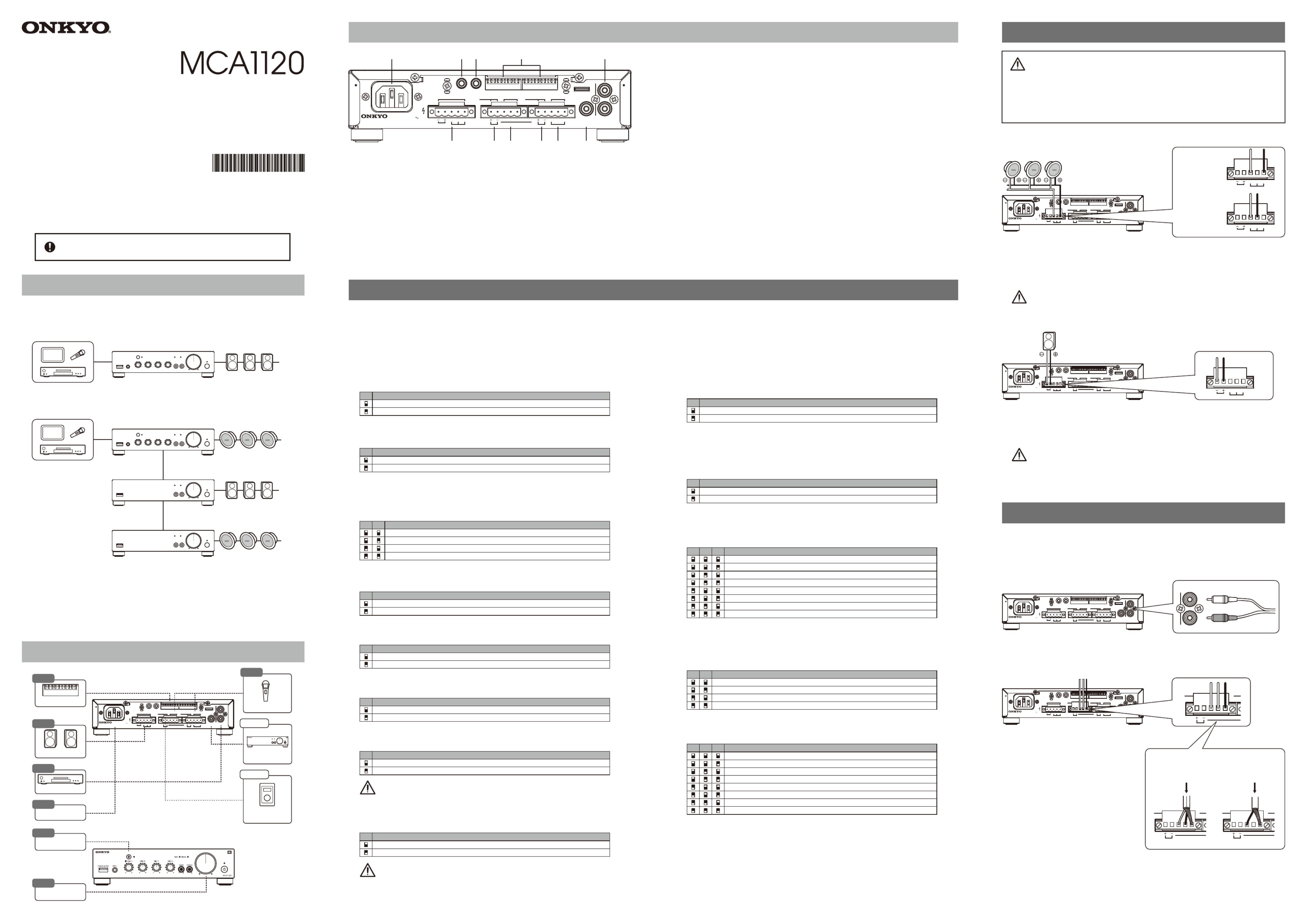
MCA1120 Rear Panel
① AC Inlet (IEC C13, 100V-240V 50/60 Hz) (⇒ see Step 5)
② SPEAKER OUT Terminals (Euroblock)
NOTE
It is important to read “Step 2: Connecting Speakers” before attempting to use this terminal.
IMPROPER SETUP CAN RESULT IN MALFUNCTION OR FIRE. (⇒ see Step 2)
③ Remote Volume Controller Terminal (Euroblock)
Use for connecting a commercially available volume control. (⇒ see Option 2)
④ MIC 2 / LINE 3 Input Terminals (Euroblock)
Use for connecting either a Mic Level or Line Level device. (⇒ see Step 4)
①
② ③ ④ ⑤ ⑥ ⑦
⑧⑨ ⑩ ⑪
1 2 3 4 5 6 7 8 9 101 2 3 4 5 6 7 8 9 10
SPEAKER OUT
Class2
Wiring
IR IN RS232
AC
INLET
REMOTE VOL MIC 2 MANUAL MUTE MIC 1
SET UP SOUND MODE L
R
COM 70 V
2 Ω - 8 Ω
100 V
H
R G
( L LINE 3
)
EC MIC 2 ECH
(MONO)
MODEL NO. MCA1120
100 -240 V
50 / 60 Hz
Input :
LINE 2PRE OUT
⑤ Manual Mute Terminal for MIC 1 Input (Euroblock)
Use for connecting a Push-to-Talk switch for Priority Mute Paging. (⇒ see Step 4)
⑥ MIC 1 Input Terminals (Euroblock)
Use for connecting a wired microphone. (⇒ see Step 4)
For wireless microphone systems, use MIC 2 / LINE 3 terminal.
⑦ PRE OUT Terminal (RCA Mono)
This is a variable line output linked to the Master Volume.
Use this output to link to expansion amplifier PCA1120 like in Example B.
(⇒ see Option 1 for Setup)
⑧ LINE 2 Input Terminals (RCA Stereo)
Use to connect an external player such as CD, Music Streamer, etc. (⇒ see Step 3)
⑨ IR IN (3.5mm Mini, Mono / 2-pole)
For use with an external infrared controller.
⑩ RS232 (3.5mm Mini, Stereo / 3-Pole)
For use with an external controller, or for Custom EQ programming.
: To prevent damage, unplug the power cord when inserting/removingIMPORTANT
the RS232 cable.
⑪ DIP Switches
See Step 1 for instructions on how to set the DIP switches.
Step 2 : Connecting Speakers
1. Set #8 [ SET UP ] DIP switch [ SPEAKER OUT ] to [ Hi-Z ].
2. Connect the [ 100V ] or [ 70V ] terminal of SPEAKER OUT to
the + terminal on your speakers. Next, connect the [ COM ] to
the ‒ terminal on your speakers.
■ Hi-Z (High Impedance) Connections
1. Set #8 [ SET UP ] DIP Switch [ SPEAKER OUT ] to [ Lo-Z ].
2.
Connect the + terminal of SPEAKER OUT to the + terminal on your speakers.
Next, connect the - to the ‒ terminal on your speakers.
■ Lo-Z (Low Impedance) Connections
12345678910123 45678910
SPEAKER OUT
Class2
Wiring
IR IN RS232
AC
INLET
REMOTE VOL MIC 2 MANUAL MUTE MIC 1
SET UP SO UND MO DE L
R
COM 70 V
2 Ω - 8 Ω
100 V
H
R G( L LINE 3 )
EC MIC 2 ECH
(MONO )
MODEL NO. MCA1120
100 -240 V
50 / 60 Hz
Input :
LINE 2PRE OUT
123 4567891012345678910
SPEAKER OUT
Class2
Wiring
IR IN RS232
AC
INLET
REMOTE VOL MIC 2 MANUAL MUTE MIC 1
SET UP SO UND MO DE L
R
COM 70 V
2 Ω - 8 Ω
100 V
H
R G
(
L LINE 3 )
EC MIC 2 ECH
(MONO )
MODEL NO. MCA1120
100 -240 V
50 / 60 Hz
Input :
LINE 2PRE OUT
SPEAKER OUT
COM 70 V
2 Ω - 8 Ω
100 V
∼∼
∼∼
■ When connecting
100V line
speakers
■ When connecting
70V line
speakers
SPEAKER OUT
COM 70 V
2 Ω - 8 Ω
100 V
SPEAKER OUT
COM 70 V
2 Ω - 8 Ω
100 V
・ See the "front panel" section on the back.
・ Connect the external player to the LINE 2 terminals with the RCA cable.
You can use either L or R terminal for the output of monaural player.
■ LINE 3 Connection
■ LINE 1 Connection
1. Set #6 [ SET UP ] DIP Switch [ MIC 2 / LINE 3 ]
to [ LINE 3 ].
If this setting is missing, the in-phase signal
(melody, bass line, etc.) will not come out.
2. Connect the output of the external
player to the LINE 3 terminal with
Euroblock.
You can use either L or R terminal for
the output of monaural player.
Stereo signals are internally mixed into mono.
■ LINE 2 Connection
Step 3 : Connecting External Players
123 4567891012345678910
SPEAKER OUT
Class2
Wiring
IR IN RS232
AC
INLET
REMOTE VOL MIC 2 MANUAL MUTE MIC 1
SET UP SO UND MO DE L
R
COM 70 V
2 Ω - 8 Ω
100 V
H
R G( L LINE 3 )
EC MIC 2 ECH
(MONO )
MODEL NO. MCA1120
100 -240 V
50 / 60 Hz
Input :
LINE 2PRE OUT
RCA
L
R
LINE 2
MCA1120
In the main space
MCA1120
In the VIP area
PCA1120
In the terrace area
PCA1120
■ Example A
Standalone use of the MCA1120 as a Background Music(BGM) and Paging system.
System Configuration Examples
■ Example B
Expanding the system using the PCA1120(x2 shown) and additional speakers.
123 4567891012345678910
SPEAKER OUT
Class2
Wiring
IR IN RS232
AC
INLET
REMOTE VOL MIC 2 MANUAL MUTE MIC 1
SET UP SO UND MO DE L
R
COM 70 V
2 Ω - 8 Ω
100 V
H
R G
(
L LINE 3 )
EC MIC 2 ECH
(MONO )
MODEL NO. MCA1120
100 -240 V
50 / 60 Hz
Input :
LINE 2PRE OUT
REMOTE VOL MIC 2 MANUAL MUTE MIC 1
H
R G
( L LINE 3 )
EC MIC 2 ECH
Step 1 : DIP Switch Settings
■ Example C (IMAGE NOT SHOWN)
Driving a passive subwoofer with the PCA1120.
Lo-Z speakers
Composite impedance 2Ω or more
・ ・ ・
Hi-Z speakers
Rated total 120W or less
Drip-proof speaker
Hi-Z 120W or less /
Lo-Z 2Ω or more
♪
・ Do not connect the Lo-Z speakers to the Hi-Z terminals.
・ When connecting multiple speakers, make sure that the total impedance is more than
the value of setting #9 [ Speaker Lo-Z ] of SET UP DIP switch.
・ Do not use the high impedance 70V line and 100V line terminals at the same time.
・ Make sure that the total rated input power of the connected speakers is 120W or less.
■ Case of
Stereo Source
From
External Player
From
External Player
■ Case of
Monaural Source
REMOTE VOL MIC 2 MANUAL MUTE MIC 1
H
R G( L LINE 3 )
EC MIC 2 ECH
REMOTE VOL MIC 2 MANUAL MUTE MIC 1
H
R G( L LINE 3 )
EC MIC 2 ECH
∼∼ ∼∼
SN 29403546A
2* 9403546A
See website for detailed connections.
Bluetooth Playback
Step 6
Setup and Operation Steps
DIP Switches
12345678910
Step 1
Speakers
Step 2
AC Power
Step 5
External Player
Step 3
123 4567891012345678910
SPEAKER OUT
Class2
Wiring
IR IN RS232
AC
INLET
REMOTE VOL MIC 2 MANUAL MUTE MIC 1
SET UP SO UND MO DE L
R
COM 70 V
2 Ω - 8 Ω
100 V
H
R G
(
L LINE 3 )
EC MIC 2 ECH
(
MONO)
MODEL NO. MCA1120
100 -240 V
50 / 60 Hz
Input :
LINE 2PRE OUT Option 1
Speaker Expansion
Option 2
Remote
Volume Controller
Microphones
Step 4
Adjusting Volume
Step 7
PCA1120
・ ・ ・
・ ・ ・
♪
Lo-Z speakers
Composite impedance 2Ω or more
・ ・ ・
The PCA1120 has built-in crossover settings for this application.
・ Connect AC power cord in final step. Do not connect AC power cord before this step.
It may cause electric shock.
・ Check the connection pins of Euroblock and Lo-Z / Hi-Z settings of DIP switches
according to speaker specifications.
If these are not matched, it may cause malfunction or fire.
Pay close attention to speaker setting /
connection! It may cause malfunction or fire.
This product is intended for commercial/professional use.
It should be installed only by a specially-trained technician.
In this configuration with multiple rooms and speaker types,
the MCA1120 controls the overall volume of the system, while each
PCA1120 volume level can be adjusted for its room.
*
・ Connect the supplied AC power cord to the AC Inlet and plug to AC outlet.
Step 5 : Connecting Power Cord
12345678910123 45678910
SPEAKER OUT
Class2
Wiring
IR IN RS232
AC
INLET
REMOTE VOL MIC 2 MANUAL MUTE
SET UP SO UND MO DE L
R
COM 70 V
2 Ω - 8 Ω
100 V
H
R G( L LINE 3 )
EC MIC 2 ECH
(MONO )
MODEL NO. MCA1120
100 -240 V
50 / 60 Hz
Input :
LINE 2PRE OUT
The BluetoothⓇ word mark and logos
are registered trademarks owned by
Bluetooth SIG, Inc.
Printed in Malaysia
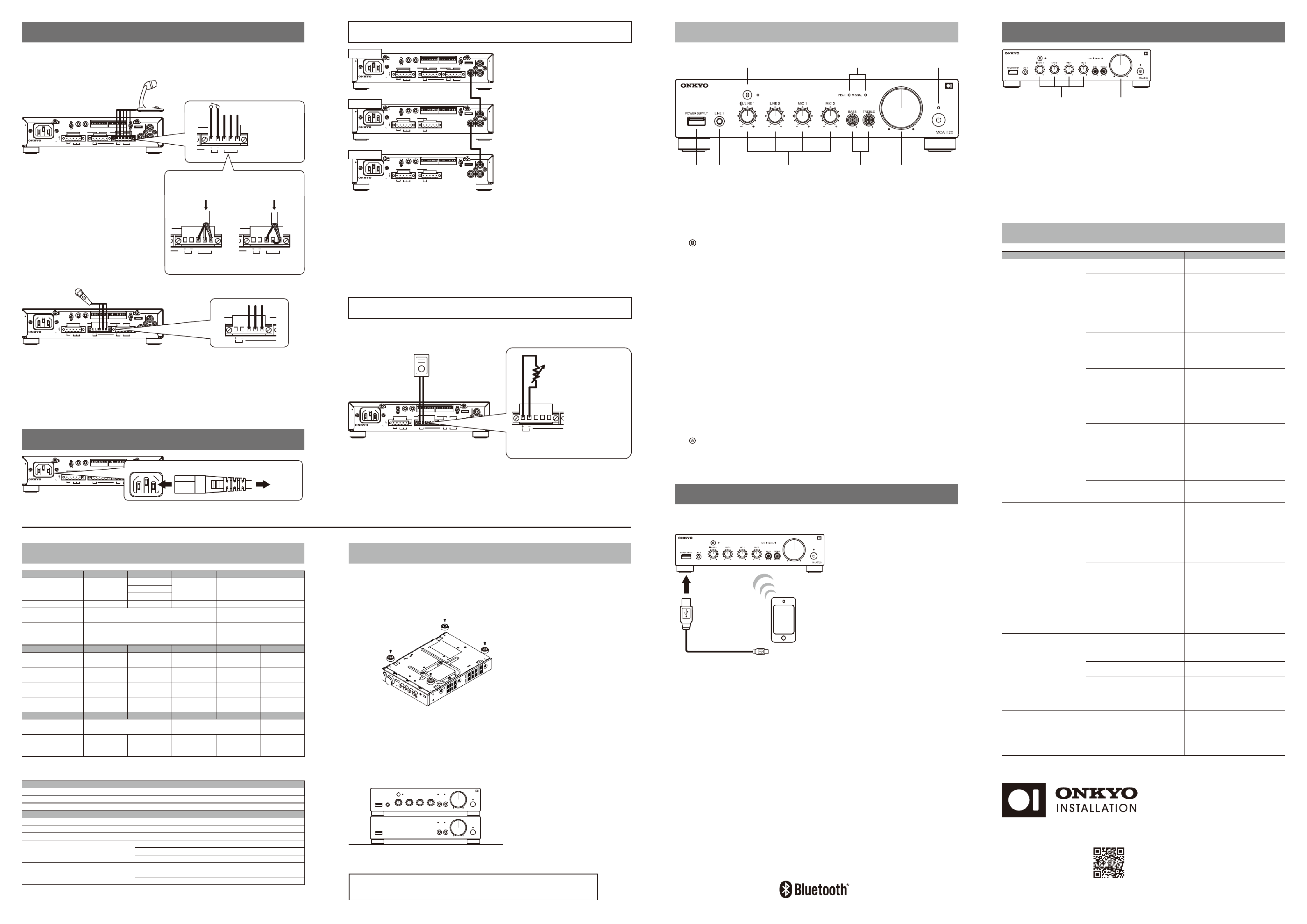
MCA1120 Front Panel
① USB Power Supply Terminal (5V / 2.1A)
② LINE 1 Input Terminals (3.5mm Mini, Stereo)
Connect a portable audio player, tablet, etc..
NOTE: When you connect a device into LINE 1 input during Bluetooth playback, Bluetooth audio
stops and LINE 1 sound will be output.
③ [ ] Bluetooth Button / Indicator
Connect Bluetooth-enabled device such as portable audio player, tablet, etc.
During pairing mode, the indicator blinks. When the indicator is lit, the device is connected.
NOTE: When you connect a device via Bluetooth while LINE 1 input is being used, LINE 1 input
sound will stop and Bluetooth sound will be output.
④ Input Volume LINE 1(Bluetooth) / LINE 2 / MIC 1 / MIC 2 (LINE 3)
To Adjust each input level.
To adjust the level of LINE 3, use knob for MIC 2.
⑤ SIGNAL / PEAK Indicator
SIGNAL Indicator
It lights up when the speaker output level becomes around - 46 dB or more of the rated
output.
It may not light up when the output level is low. It is not malfunction. Blinks when muted.
(Muting function is done only by IR IN or RS232. This unit does not have this operation.)
PEAK indicator
Lights up when the speaker output level reaches its peak (around - 3 dB from the rated
output).
If it lights continuously, the sound maybe distorted. Lower the volume if necessary.
⑥ BASS / TREBLE
You can adjust BASS (low frequency) and TREBLE (high frequency) from -10 dB to +10 dB.
Use a small screwdriver, etc. .
⑦ Master Volume
Adjust the output level to the speaker and PRE OUT jack. Turning it to the right will increase
the volume. If you add PCA1120, you can raise or lower the system volume by this knob.
⑧ [ ] Power Button / Indicator
Switch the Power Standby / On. The indicator lights up as follows.
RedStandby
GreenOn
① ②
③
④
⑤
⑥ ⑦
⑧
Release voltage:
DC 24 V or less
Remote volume control by 10kΩ
potentiometer (B-curve).
・ Remote volume control by 10kΩ potentiometer. Remote volume and master volume function
in series. If either is at minimum, there will be no sound.
Remote volume
Option 2 :
Remote Volume Control
123 45678910123 45678910
SPEAKER OUT
Class2
Wiring
IR IN RS232
AC
INLET
REMOTE VOL MIC 2 MIC 1MANUAL MUTE
SET UP SO UND MO DE L
R
COM 70 V
2 Ω - 8 Ω
100 V
H
R G( L LINE 3 )
EC MIC 2 ECH
(
MONO )
MODEL NO. MCA1120
100 -240 V
50 / 60 Hz
Input :
LINE 2PRE OUT
Benefits of combining MCA1120 with one or more PCA1120(s).
a. Additional speaker zones can be added (See Example B).
b. A passive subwoofer can be added to the system (See Example C).
c. Both the MCA1120 and PCA1120 include independent Preset EQ and HPF, allowing you to
tailor the sound of each speaker area.
d. The MCA1120 Master Volume control can be used to adjust overall system volume for
all areas since its PRE OUT terminal is variable. In this application, set the PCA1120 volume
control to the center position (12 o’clock). Alternatively, you can adjust each PCA1120
volume independently.
Option 1 :
Expanding Speakers
with PCA1120
123 45678910123 45678910
SPEAKER OUT
Class2
Wiring
IR IN RS232
AC
INLET
REMOTE VOL MIC 2 MANUAL MUTE MIC 1
SET UP SO UND MO DE L
R
COM 70 V
2 Ω - 8 Ω
100 V
H
R G
(
L LINE 3 )
EC MIC 2 ECH
(
MONO )
MODEL NO. MCA1120
100 -240 V
50 / 60 Hz
Input :
LINE 2PRE OUT
MCA1120
123 45678910123 45678910
SPEAKER OUT
Class2
Wiring
IR IN RS232
AC
INLET
REMOTE VOL
SET UP SO UND MO DE L
R
COM 70 V
2 Ω - 8 Ω
100 V
(MONO ) (MONO/ST EREO)
LINE INLINE OUT
MODEL NO. PCA1120
100 -240 V
50 / 60 Hz
Input :
PCA1120
123 45678910123 45678910
SPEAKER OUT
Class2
Wiring
IR IN RS232
AC
INLET
REMOTE VOL
SET UP SO UND MO DE L
R
COM 70 V
2 Ω - 8 Ω
100 V
(MONO ) (MONO/ST EREO)
LINE INLINE OUT
MODEL NO. PCA1120
100 -240 V
50 / 60 Hz
Input :
PCA1120
1. Connect the PRE OUT terminal of
the MCA1120 and the LINE IN
terminal (L or R) of PCA1120
with the monaural RCA cable.
2. Follow the instruction manual of
the PCA1120, set the DIP switch
and connect the speaker.
3. For further expansion, connect to
another PCA1120 in series from
the LINE OUT terminal of the
PCA1120.
REMOTE VOL MIC 2 MANUAL MUTE MIC 1
H
R G( L LINE 3 )
EC MIC 2 ECH
When Bluetooth wireless connection
does not work, wire connect to LINE 1.
You can wirelessly play music on a Bluetooth-enabled device, such as a portable audio player, tablet, etc.
USB POWER SUPPLY terminal supplies power to USB compatible devices.
Step 6 : BluetoothⓇ Operation
■ MIC 1 Connection No-voltage contact
Short-circuit current: 3 mA or less
Open circuit voltage: DC 24 V or less
Microphone with contact
・ Mic Ducker and Feedback Suppressor can be used with either MIC 1/2.
・ Connect the microphone with paging function to MIC 1, and wireless microphone to MIC 2.
・ Since there is no phantom power, use battery-powered condenser microphone.
・ Normal dynamic microphone can be used with either MIC 1/2 Input.
MicrophoneMicrophone
Short the terminals
between [C] and [E]
■ MIC 2 Connection
1. Set #6 [ SET UP ] DIP Switch [ MIC 2 / LINE 3 ] to [ MIC 2 ].
2. Use #7 [ SET UP ] DIP Switch [ MIC2 AMP ] to select between
[ On ] (Mic level) or [ Off ] (Line Level).
If using a wireless MIC, this selection should be based off of the output level of
the microphone receiver unit.
3. Connect the output of the microphone to the MIC 2 terminal with Euroblock.
For the connection method of the shielded wire, refer to the section on MIC 1 Connection.
123 45678910123 45678910
SPEAKER OUT
Class2
Wiring
IR IN RS232
AC
INLET
REMOTE VOL MIC 2 MANUAL MUTE MIC 1
SET UP SO UND MO DE L
R
COM 70 V
2 Ω - 8 Ω
100 V
H
R G( L LINE 3 )
EC MIC 2 ECH
(MONO )
MODEL NO. MCA1120
100 -240 V
50 / 60 Hz
Input :
LINE 2PRE OUT
REMOTE VOL MIC 2 MANUAL MUTE MIC 1
H
R G
( L LINE 3 )
EC MIC 2 ECH
Step 4 : Connecting Microphones
1. Set the Input Volume to the position of the center (12 o'clock) connected
to the external source device used by the main .
2. Keep the other input volumes to a minimum.
3. Play back the BGM and adjust the master volume to the optimum volume.
4. With the master volume decided in step 3 fixed, while outputting sound
from other devices and microphones, gradually raise each input volume to
balance the volume.
・ If the volume is low even if the other input volume is maximized in step 4, lower the input
volume in step 1 slightly and repeat from step 2.
Step 7 : Adjusting Volume
Input Volume Master volume
Since some parts such as cooling fans are consumable parts, it is necessary
to replace the parts according to deterioration.
For replacement, please contact the store you purchased or Onkyo service.
Troubleshooting
AC power cordAC Inlet
To AC outlet
∼∼∼
∼∼∼
8.5 W x 2.2 H x 12.6 D [ inch ](w/o legs 1.75H)
Power Amplifier : PCA1120Option
Specifications and features are subject to change without notice.
Rack Mount Kit : IRK-44-3
Product Weight 3.6kg(7.9lbs)
215 W x 55 H x 319 D [ mm ](w/o legs 44.5H)
1 RU high (w/o Foots), half rack wideDimensions
215W @ Rated Power, 10W @ IdlingPower Consumption
AC100 − 240V(50/60 Hz)Power Supply
0 − 40 ℃ @ Non−condensingOperating Temperature
5V/2.1A (Not For Audio Playback)USB Power Supply
Communication Range Max. 10m (Line of sight approx.)
Communication System Version5.0
Bluetooth & USB
General
*1 : MIC 2 and LINE 3 are exclusive inputs. Only one can be used.
Speaker Output Lo−Z (2Ω) Lo−Z (4−8Ω)
Hi−Z (70, 100V) Measurement Condition
Rated Power
120W × 1ch 1kHz
120W × 1ch(4Ω)
120W × 1ch
80W × 1ch(6Ω)
60W × 1ch(8Ω)
Exclusive Input Bluetooth --- MIC 2 *1 --- LINE 3 *1
Lo−Z (2Ω) Hi−Z (70V) Hi−Z (100V) PRE OUTLo−Z (4−8Ω)
Output
Rated Load 2Ω 2kΩ82Ω41Ω4−8Ω
Max. Output Voltage 15.5Vrms 22Vrms 70Vrms 100Vrms 1Vrms
Output Terminal Euroblock Euroblock Monaural RCA
Balanced (−/+) Balanced (COM / 70 or 100V) Unbalanced
43kΩ 14kΩ 14kΩ 2kΩ 2kΩ
Input Impedance
−14dBV −10dBV −10dBV −50dBV −50dBV
Input Sensitivity
Input Terminal
Stereo Mini (3.5mm)
Stereo RCA EuroBlock EuroBlock EuroBlock
Unbalanced Unbalanced Unbalanced Balanced Balanced
Input LINE 1 LINE 2 LINE 3 *1 MIC 2 *1MIC 1
Signal-to-Noise Ratio
≦−90dB
LINE 2 input volume Max.,
other input volume Min.,
with IEC−C filter
Frequency Response Reference 0dB @ 3W, 1kHz 20 Hz − 20 kHz(+0dB、−6dB)
1kHz @ Full Rated Power≦1.0 % ≦0.5 %≦0.5 %
THD+N
NOTE:
H (Hot, +),
C (Cold, −),
E (Earth, GND)
REMOTE VOL MIC 2 MANUAL MUTE MIC 1
H
R G( L LINE 3 )
EC MIC 2 ECH
123 45678910123 45678910
SPEAKER OUT
Class2
Wiring
IR IN RS232
AC
INLET
REMOTE VOL MIC 2 MIC 1MANUAL MUTE
SET UP SO UND MO DE L
R
COM 70 V
2 Ω - 8 Ω
100 V
H
R G( L LINE 3 )
EC MIC 2 ECH
(MONO )
MODEL NO. MCA1120
100 -240 V
50 / 60 Hz
Input :
LINE 2PRE OUT
■ Using a 2-core
shielded wire
From microphone
■ Using a single-core
shielded wire
REMOTE VOL MIC 2 MANUAL MUTE MIC 1
H
R G
( L LINE 3 )
EC MIC 2 ECH
REMOTE VOL MIC 2 MANUAL MUTE MIC 1
H
R G
(
L LINE 3 )
EC MIC 2 ECH
∼∼ ∼∼
From microphone
Installing your amplifier
Do not block any ventilation openings.
By playing your equipment at higher level for a long period, the protection circuit maybe activated by
high temperature and the sound may drop.
2. Attach the rack mount brackets IRK-44-3 by referring to the instruction
manual.
3. Install the unit in your rack system.
1. Remove four feet from the bottom of the unit.
■ Rack Mount
When stacking amplifiers without using a cabinet, keep enough space from the top surface
of the unit.
Do not remove feet for air ventilation.
■ Stacking Amplifiers
Check whether the external device
outputs the signal or not.
Set the DIP switch to [ LINE 3 ].
Match impedance and connection
of speaker and this unit.
Check total rated power of speakers
is not over rated power of this unit.
Set #7 [ MIC 2 AMP ] of SET UP DIP
Switch to [ On ].
Specification of speakers, settings
of DIP switch and connected
speaker terminal position are not
matched.
Using Mic level output microphone
with MIC amp setting off.
[ LINE 3 ] Sound is loud or distorted.
#6 [ MIC 2 / LINE 3 ] of SET UP DIP
Switch is set to [ MIC 2 ].
Unplug and plug AC plug of this
unit and connected Bluetooth
equipment.
If it did not work, connect to [ LINE 1 ]
with 3.5mm mini plug cord.
Shut down the application which
interrupt Bluetooth.
Place the unit far from microwave or
cordless phones.
MicroPC function in this unit
locked up.
Sound is interrupted by some
applications.
Radio wave interference may
occur in the vicinity of
components, such as microwave
ovens or cordless phones.
Bluetooth
- Cannot connect
- is unstable
- is interrupted
−The issue may be fixed by
restarting this unit.
During the power is on, press and
hold power button for five or more
seconds.
Indicator blinks in red, then release
the button.
Operation is unstable
Cannot operate
Power indicator blinks and
- No power
- No sound
- Sound interrupted
Volume is not up at certain
level
No Sound
- Volume is low at MIC input
Make sure bare speaker wires are
not touching each other.
Set #1 [ Keylock ] of SET UP DIP
Switch to [ Unlock ] position.
Then unplug AC power plug.
Then plug AC power plug after
more than 20 seconds.
Keylock is activated.
Only power button and master
volume work.
Speaker cables are short-circuited.
Condition Cause Measures
・ Check total rated power of
speakers is not overrated power
of this unit.
Check settings of Bass/Treble.
Bass/Treble setting is not correct.
Volume level is not set correctly.
Match the setting of impedance of
Speakers.
Speaker setting is not correct.
・ Adjust output level of connected
player.
・ Adjust [ Input Volume ] level.[ Particular input ]
INPUT VOLUME level is low.
Turn up the output volume level of
the player.
When the audio volume of your
headphone output or Bluetooth
device is set low, the playback of
audio may be unavailable.
[ LINE 1 ] Volume level of external
player is not correct.
Cannot turn on the unit
No sound
- Volume is very low
- Sound is distorted
- Noise can be heard
at all inputs
No sound
- Volume is very low
- Sound is distorted
at particular input
Cannot turn on the unit by
Auto Power On
The power cord is not plugged.
The protective circuit function is
activated.
Output music signal of connected
player is very low.
Make sure that the power cord is
properly plugged into the wall outlet.
Unplug the power cord from the wall
outlet.
Check speaker wires, then plug it
in again after a few minutes.
Turn up the volume of player.
Set the master volume at center.
Check the connection wire with
external device.
No input signal.
Make sure the unit has plenty of
space for ventilation around it,
wait for the unit to cool down
sufficiently, and then try turning it
on again.
The temperature of the unit rose
abnormally.
More detailed information of "Troubleshooting" is posted on the Web.
If symptoms do not improve even if referring to them, please contact Onkyo service.
■ Pairing
1. While the power of this unit is on, press the Bluetooth button.
The indicator flashes and this unit is into pairing mode.
2. Enable (turn on) the Bluetooth function of the source device (tablet, etc.) ,
and then select "Onkyo MCA1120 XXXXXX".
If a password is requested, enter "0000".
When the pairing is completed, the indicator lights steadily.
To connect another Bluetooth device, repeat from step 1.
This unit can store maximum eight devices.
■ Playing Back
1. While the power of this unit is on, make a Bluetooth connection of a tablet,
etc. and this unit.
2. Play music files.
3. Raise the volume of the tablet etc..
When you connect a device to LINE 1 input terminal during Bluetooth connection,
the Bluetooth audio stops and LINE 1 sound will be output.
<U.S.A.>
18 Park Way, Upper Saddle River, N.J. 07458, U.S.A.
Tel: 800-225-1946, 201-818-9200
Fax: 201-785-2650
http://www.onkyoinstallation.com
<Germany>
Gutenbergstrasse 3, 82178 Puchheim, Germany
Tel: +49-8142-4401-0 Fax: +49-8142-4208-213
https://www.eu.onkyo.com
<PRC>
302, Building 1, 20 North Chaling Rd., Xuhui District,
Shanghai, China 200032,
Tel: +86-21-52131366 Fax: +86-21-52130396
http://www.cn.onkyo.com
1. Connect the output of the microphone
to the MIC 1 terminal with Euroblock.
2. If necessary, connect the PTT
(Push-To-Talk) switch for paging
to the MANUAL MUTE [+] / [−]
terminals
You can mute the input sound other than
MIC 1 while pressing the PTT switch.
(Paging Function)
Adjust the total volume and
mixing level of the external
players and microphones.
©2018 Onkyo Marketing Corporation
1-10-5 Yokoami,Sumida-ku,Tokyo 130-0015 Japan
http://www.onkyoinstallation.com
1. Set to [ Volume Control(10kΩ) ] of #5 [ Volume Control ] of
SET UP DIP switch.
2. Connect the external volume(10kΩ, B-curve) to the Remote Volume
Controller terminal with Euroblock.
Specification
Produktspezifikationen
| Marke: | Onkyo |
| Kategorie: | Empfänger |
| Modell: | MCA1120 |
Brauchst du Hilfe?
Wenn Sie Hilfe mit Onkyo MCA1120 benötigen, stellen Sie unten eine Frage und andere Benutzer werden Ihnen antworten
Bedienungsanleitung Empfänger Onkyo

3 Oktober 2024
8 September 2024
3 September 2024
30 August 2024
26 August 2024
16 August 2024
11 August 2024
8 August 2024
6 August 2024
1 August 2024
Bedienungsanleitung Empfänger
- Empfänger Asus
- Empfänger Belkin
- Empfänger Exibel
- Empfänger Hama
- Empfänger Audio-Technica
- Empfänger LogiLink
- Empfänger Logitech
- Empfänger Manhattan
- Empfänger Medion
- Empfänger Nedis
- Empfänger Philips
- Empfänger Sandberg
- Empfänger Sony
- Empfänger Zalman
- Empfänger Panasonic
- Empfänger Roland
- Empfänger MX Onda
- Empfänger Bosch
- Empfänger Vox
- Empfänger TechniSat
- Empfänger Yamaha
- Empfänger Velleman
- Empfänger Neumann
- Empfänger CSL
- Empfänger Devolo
- Empfänger Schwaiger
- Empfänger Alecto
- Empfänger Conrad
- Empfänger Denver
- Empfänger EMOS
- Empfänger Gira
- Empfänger König
- Empfänger MarQuant
- Empfänger Renkforce
- Empfänger Bush
- Empfänger Thomson
- Empfänger Trevi
- Empfänger Blaupunkt
- Empfänger Grundig
- Empfänger Kenwood
- Empfänger Sharp
- Empfänger Hilti
- Empfänger Pyle
- Empfänger Golden Age Project
- Empfänger Salora
- Empfänger Telestar
- Empfänger Aiwa
- Empfänger AKG
- Empfänger Auna
- Empfänger Bang And Olufsen
- Empfänger Bose
- Empfänger Bowers And Wilkins
- Empfänger Caliber
- Empfänger Maxview
- Empfänger Denon
- Empfänger Pioneer
- Empfänger Geemarc
- Empfänger Jabra
- Empfänger JBL
- Empfänger JVC
- Empfänger Klipsch
- Empfänger Krüger And Matz
- Empfänger Meliconi
- Empfänger Motorola
- Empfänger Nokia
- Empfänger Optoma
- Empfänger Sennheiser
- Empfänger Shure
- Empfänger Technics
- Empfänger Teufel
- Empfänger Vivanco
- Empfänger Hifonics
- Empfänger Megasat
- Empfänger Smartwares
- Empfänger Akai
- Empfänger Alden
- Empfänger Dual
- Empfänger Ferguson
- Empfänger GoGEN
- Empfänger Hyundai
- Empfänger Orava
- Empfänger Strong
- Empfänger Tesla
- Empfänger Imperial
- Empfänger Tascam
- Empfänger Zoom
- Empfänger Garmin
- Empfänger Nexa
- Empfänger Sencor
- Empfänger Goobay
- Empfänger Lindy
- Empfänger Astro
- Empfänger Plantronics
- Empfänger Fenton
- Empfänger TOA
- Empfänger Rotel
- Empfänger Musway
- Empfänger Tripp Lite
- Empfänger Audio Pro
- Empfänger Cabasse
- Empfänger Canton
- Empfänger Dali
- Empfänger Harman Kardon
- Empfänger Inateck
- Empfänger Magnat
- Empfänger Marmitek
- Empfänger Marshall
- Empfänger Naim
- Empfänger Power Dynamics
- Empfänger Samson
- Empfänger Scosche
- Empfänger Skytec
- Empfänger Tangent
- Empfänger Vonyx
- Empfänger Peavey
- Empfänger Marshall Electronics
- Empfänger Sagem
- Empfänger Simrad
- Empfänger AVM
- Empfänger Xoro
- Empfänger Karma
- Empfänger Atlas
- Empfänger Reely
- Empfänger Edision
- Empfänger GigaBlue
- Empfänger Humax
- Empfänger Kathrein
- Empfänger Metronic
- Empfänger Smart
- Empfänger Topfield
- Empfänger Xtrend
- Empfänger Zehnder
- Empfänger Icom
- Empfänger Brondi
- Empfänger Alpine
- Empfänger Rupert Neve Designs
- Empfänger NAD
- Empfänger Fender
- Empfänger Renegade
- Empfänger Ebode
- Empfänger LTC
- Empfänger Vincent
- Empfänger Vision
- Empfänger Hager
- Empfänger Behringer
- Empfänger Mackie
- Empfänger Omnitronic
- Empfänger Thomann
- Empfänger MB Quart
- Empfänger Marantz
- Empfänger Monoprice
- Empfänger Arcam
- Empfänger Cambridge
- Empfänger Crown
- Empfänger Dynacord
- Empfänger Ecler
- Empfänger Luxman
- Empfänger Monacor
- Empfänger Rockford Fosgate
- Empfänger TEAC
- Empfänger Thorens
- Empfänger Crunch
- Empfänger Chamberlain
- Empfänger JUNG
- Empfänger Aplic
- Empfänger InLine
- Empfänger Sangean
- Empfänger Classé
- Empfänger Optex
- Empfänger Revox
- Empfänger Sherwood
- Empfänger Jamo
- Empfänger AXTON
- Empfänger Clarion
- Empfänger Mac Audio
- Empfänger Kogan
- Empfänger Genie
- Empfänger Humantechnik
- Empfänger T-Mobile
- Empfänger Skytronic
- Empfänger Yaesu
- Empfänger Audizio
- Empfänger ESX
- Empfänger Reloop
- Empfänger HQ
- Empfänger Pinnacle
- Empfänger Block
- Empfänger Rega
- Empfänger SYNQ
- Empfänger Amazon
- Empfänger Insignia
- Empfänger August
- Empfänger Audison
- Empfänger DataVideo
- Empfänger RCF
- Empfänger Electro-Voice
- Empfänger Cyrus
- Empfänger Scansonic
- Empfänger Sogo
- Empfänger Cisco
- Empfänger Delta Dore
- Empfänger Salus
- Empfänger Sonos
- Empfänger Yorkville
- Empfänger MIPRO
- Empfänger Elektrobock
- Empfänger FiiO
- Empfänger Boss
- Empfänger IFM
- Empfänger Intertechno
- Empfänger American Audio
- Empfänger Anthem
- Empfänger Roksan
- Empfänger Engel Axil
- Empfänger Alto
- Empfänger Kopul
- Empfänger Chord
- Empfänger Saramonic
- Empfänger Kramer
- Empfänger Hertz
- Empfänger Pro-Ject
- Empfänger Aeon Labs
- Empfänger Vaddio
- Empfänger Galaxy Audio
- Empfänger HQ Power
- Empfänger Ibiza Sound
- Empfänger Kicker
- Empfänger Warm Audio
- Empfänger Polk
- Empfänger Line 6
- Empfänger Bogen
- Empfänger DBX
- Empfänger Radial Engineering
- Empfänger McIntosh
- Empfänger Sonance
- Empfänger Jensen
- Empfänger ELAC
- Empfänger Fostex
- Empfänger JL Audio
- Empfänger Pyle Pro
- Empfänger PreSonus
- Empfänger Qtx
- Empfänger Hartke
- Empfänger ART
- Empfänger Deaf Bonce
- Empfänger Fredenstein
- Empfänger LD Systems
- Empfänger RDL
- Empfänger Audiolab
- Empfänger Oculus VR
- Empfänger Summit Audio
- Empfänger Homematic IP
- Empfänger Black Lion Audio
- Empfänger Dreambox
- Empfänger Bluesound
- Empfänger Solid State Logic
- Empfänger RME
- Empfänger GlobalSat
- Empfänger Chandler
- Empfänger DAP
- Empfänger DAP Audio
- Empfänger Definitive Technology
- Empfänger Denson
- Empfänger Devialet
- Empfänger DIO
- Empfänger DLS
- Empfänger Focal
- Empfänger Focusrite
- Empfänger Formuler
- Empfänger Fusion
- Empfänger Graupner
- Empfänger Ground Zero
- Empfänger Helix
- Empfänger Hirschmann
- Empfänger Homecast
- Empfänger Infinity
- Empfänger Iriver
- Empfänger JB Systems
- Empfänger Koda
- Empfänger Lanzar
- Empfänger Legamaster
- Empfänger Medeli
- Empfänger Mercury
- Empfänger Monitor Audio
- Empfänger Mtx Audio
- Empfänger Mvision
- Empfänger Naxa
- Empfänger Octagon
- Empfänger Phoenix Gold
- Empfänger Raymarine
- Empfänger REL Acoustics
- Empfänger Selfsat
- Empfänger Soundstream
- Empfänger Stagg
- Empfänger Steren
- Empfänger Stinger
- Empfänger Sunstech
- Empfänger Terratec
- Empfänger ACV
- Empfänger AMX
- Empfänger Triax
- Empfänger Tronics
- Empfänger TV STAR
- Empfänger Universal Remote Control
- Empfänger Velodyne
- Empfänger Vivotek
- Empfänger Wharfedale
- Empfänger Winegard
- Empfänger Xsarius
- Empfänger Zgemma
- Empfänger Universal Audio
- Empfänger Phonic
- Empfänger Epcom
- Empfänger Adastra
- Empfänger Siig
- Empfänger Amiko
- Empfänger Cloud
- Empfänger Mooer
- Empfänger AudioControl
- Empfänger MXL
- Empfänger TV One
- Empfänger NAV-TV
- Empfänger StarTech.com
- Empfänger APart
- Empfänger Blackstar
- Empfänger HEOS
- Empfänger Smart-AVI
- Empfänger QSC
- Empfänger RetroSound
- Empfänger Dahua Technology
- Empfänger Proel
- Empfänger Niles
- Empfänger Panduit
- Empfänger Martin Logan
- Empfänger Metra
- Empfänger Kanto
- Empfänger PAC
- Empfänger Sound Devices
- Empfänger Speco Technologies
- Empfänger IFi Audio
- Empfänger Gefen
- Empfänger Polsen
- Empfänger Bugera
- Empfänger Russound
- Empfänger Vocopro
- Empfänger SRS
- Empfänger Comica
- Empfänger Astell&Kern
- Empfänger IMG Stage Line
- Empfänger Inovonics
- Empfänger Mosconi
- Empfänger Atlas Sound
- Empfänger FBT
- Empfänger DB Technologies
- Empfänger CYP
- Empfänger Amplicom
- Empfänger Micromega
- Empfänger Palmer
- Empfänger Jolida
- Empfänger Ampeg
- Empfänger Avalon
- Empfänger BOYA
- Empfänger Audient
- Empfänger Bang Olufsen
- Empfänger Lectrosonics
- Empfänger ATen
- Empfänger Eventide
- Empfänger Axing
- Empfänger Laney
- Empfänger Morel
- Empfänger SVS
- Empfänger KanexPro
- Empfänger Citronic
- Empfänger Crest Audio
- Empfänger Lab Gruppen
- Empfänger SPL
- Empfänger Parasound
- Empfänger Apantac
- Empfänger Brigmton
- Empfänger Axis
- Empfänger MEE Audio
- Empfänger Wet Sounds
- Empfänger Edisio
- Empfänger Pyramid
- Empfänger Stewart
- Empfänger Black Hydra
- Empfänger Linn
- Empfänger Roswell
- Empfänger Music Hall
- Empfänger Audac
- Empfänger OSD Audio
- Empfänger Match
- Empfänger Audioengine
- Empfänger Neets
- Empfänger EA
- Empfänger BZBGear
- Empfänger Crestron
- Empfänger PSSO
- Empfänger HiFi ROSE
- Empfänger Accell
- Empfänger Ibanez
- Empfänger Antelope Audio
- Empfänger Pharos
- Empfänger Kemo
- Empfänger Audix
- Empfänger Viscount
- Empfänger GOgroove
- Empfänger Avantree
- Empfänger PSB
- Empfänger Phoenix Audio
- Empfänger Extron
- Empfänger Atlona
- Empfänger Comtek
- Empfänger LYYT
- Empfänger JTS
- Empfänger Redline
- Empfänger Valueline
- Empfänger Grace Design
- Empfänger Ashdown Engineering
- Empfänger Ram Audio
- Empfänger Esoteric
- Empfänger Xantech
- Empfänger Wavtech
- Empfänger Krell
- Empfänger Artsound
- Empfänger Rolls
- Empfänger Sonifex
- Empfänger Advance Acoustic
- Empfänger Kali Audio
- Empfänger Leviton
- Empfänger Revel
- Empfänger WyreStorm
- Empfänger Wireless Solution
- Empfänger Manley
- Empfänger Klark Teknik
- Empfänger Lindell Audio
- Empfänger AVMATRIX
- Empfänger Alfatron
- Empfänger Acme United
- Empfänger Mark Levinson
- Empfänger CAD Audio
- Empfänger Dynavox
- Empfänger Key Digital
- Empfänger AER
- Empfänger Cerwin-Vega
- Empfänger Sound Ordnance
- Empfänger Majestic
- Empfänger Ocean Matrix
- Empfänger Markbass
- Empfänger AmpliVox
- Empfänger LEA
- Empfänger Memphis Audio
- Empfänger FiveO
- Empfänger Televes
- Empfänger Aquatic AV
- Empfänger DirecTV
- Empfänger Ashly
- Empfänger Fishman
- Empfänger AVPro Edge
- Empfänger Integra
- Empfänger Matrox
- Empfänger Blustream
- Empfänger CyberData Systems
- Empfänger Williams Sound
- Empfänger Sunfire
- Empfänger SoundTube
- Empfänger JETI
- Empfänger SureCall
- Empfänger Vivolink
- Empfänger WesAudio
- Empfänger ANKARO
- Empfänger NUVO
- Empfänger Audiofrog
- Empfänger Canyon
- Empfänger AMS Neve
- Empfänger Trace Elliot
- Empfänger The T.amp
- Empfänger Knoll
- Empfänger MuxLab
- Empfänger Hegel
- Empfänger Triangle
- Empfänger Whirlwind
- Empfänger Camille Bauer
- Empfänger Hughes & Kettner
- Empfänger Rocketfish
- Empfänger Dimavery
- Empfänger Palsonic
- Empfänger Musical Fidelity
- Empfänger Rexing
- Empfänger A-NeuVideo
- Empfänger Crest
- Empfänger Cranborne Audio
- Empfänger Seco-Larm
- Empfänger Primare
- Empfänger C2G
- Empfänger Fosi Audio
- Empfänger S.M.S.L
- Empfänger Aurel
- Empfänger Advance
- Empfänger AEA
- Empfänger Datapath
- Empfänger TechLogix Networx
- Empfänger PTN-electronics
- Empfänger CE Labs
- Empfänger Gold Note
- Empfänger Planet Audio
- Empfänger Lotronic
- Empfänger Audiotec Fischer
- Empfänger Sinus Live
- Empfänger Shinybow
- Empfänger Shanling
- Empfänger Fontastic
- Empfänger BC Acoustique
- Empfänger NuPrime
- Empfänger Taga Harmony
- Empfänger Creek
- Empfänger BMB
- Empfänger Valcom
- Empfänger Intelix
- Empfänger Madison
- Empfänger Topp Pro
- Empfänger Whistler
- Empfänger Powersoft
- Empfänger LinksPoint
- Empfänger Modelcraft
- Empfänger Simaudio
- Empfänger TIC
- Empfänger Mobile Crossing
- Empfänger FSR
- Empfänger Edwards Signaling
- Empfänger Lyngdorf
- Empfänger AudioSource
- Empfänger Leema
- Empfänger Quad
- Empfänger IOTAVX
- Empfänger Inter-M
- Empfänger Soundtrack
- Empfänger Canor
- Empfänger Unison Research
- Empfänger Clare Controls
- Empfänger Loxjie
- Empfänger Cayin
- Empfänger Technical Pro
- Empfänger VMV
- Empfänger Bellari
- Empfänger Comprehensive
- Empfänger PureLink
- Empfänger FoneStar
- Empfänger Glemm
Neueste Bedienungsanleitung für -Kategorien-
2 Dezember 2024
1 Dezember 2024
30 November 2024
30 November 2024
30 November 2024
30 November 2024
30 November 2024
30 November 2024
30 November 2024
29 November 2024