Mercury Mystique (1999) Bedienungsanleitung
Lesen Sie kostenlos die 📖 deutsche Bedienungsanleitung für Mercury Mystique (1999) (244 Seiten) in der Kategorie Auto. Dieser Bedienungsanleitung war für 19 Personen hilfreich und wurde von 2 Benutzern mit durchschnittlich 4.5 Sternen bewertet
Seite 1/244

1
Contents
Before driving
Introduction 2
Instrumentation 4
Controls and features 20
Seating and safety restraints 72
Starting and driving
Starting 104
Driving 112
Roadside emergencies 137
Servicing
Maintenance and care 158
Capacities and specifications 217
Customer assistance 223
Reporting safety defects (U.S. only) 235
Index 236

Introduction
2
ICONS
Indicates a warning. Read the
following section on Warnings for
a full explanation.
Indicates that vehicle information
related to recycling and other
environmental concerns will follow.
We must all play our part in
protecting the environment.
Correct vehicle usage and the
authorized disposal of waste
cleaning and lubrication materials
are significant steps toward this
aim.
BREAKING IN YOUR VEHICLE
There are no particular breaking-in
rules for your vehicle. Simply avoid
driving too fast during the first
1 600 km (1 000 miles). Vary
speeds frequently. This is
necessary to give the moving parts
a chance to break in.
WARNINGS
How can you reduce the risk of
personal injury and prevent
possible damage to others, your
vehicle and its equipment?
In this owner’s guide, answers to
such questions are contained in
comments highlighted by the
warning triangle symbol.

Introduction
3
INFORMATION ABOUT THIS
GUIDE
The information found in this guide
was in effect at the time of
printing. Ford may change the
contents without notice and
without incurring obligation.
If possible, you should avoid hard
braking for the first 1 600 km
(1 000 miles).
From 1 600 km (1 000 miles)
onwards, you can gradually
increase the performance of your
vehicle up to the permitted
maximum speeds.

Page 22
Rear window
defroster control*
4
Instrumentation
Page 55
Turn signal/high beam
Page 6
Instrument cluster
Page 54
Hazard flasher
control
Page 56
Windshield
wiper/washer
control
Page 162
Hood release
Page 20, 21
Headlamp control/
Foglamp control*
Page 54
Horn
Page 53
Tilt steering
wheel lever
Page 52
Ignition switch
Page 57
Speed control*
Page 22
Traction control*
Page 23
Power mirrors*
TRACTION
CONTROL
CHECK
ENGINE
O/D
OFF
Res
Set
Acc
CoastOff
On
E F
000123
0000
10
20
30
40
50 60 70 80
90
10 0
11 0
120
130
MPH
20
40
60
55
80
120100
140
160
180
200
1
2
0
3
x 1000
45
6
7
8
M
I
R
R
O
R
S
BRAKE
C H

5
Instrumentation
On various models the
appearance and location of
some items may differ from
those shown here. However,
the page references given
still apply.
OFFLO PNL/FLR
PANEL
A/C
FLOOR
DEF
FLR
DEF
MAX
A/C
HI
/
POWER AUDIO AM/FM SCAN
SEEK
31 2
4 5
ANS
SIDE 1-2
EJECT
VOLUME CLOCK
Page 24
Climate control system
Page 70
Anti-theft system status
indicator*
Page 32
Electronic sound system
* if equipped
Page 23
Instrument panel
dimmer switch

Instrumentation
6
Turn signal
Flashes when the left or right turn
signal or hazard lights are
activated.
0 0 0 12 3
0000
10
20
30
40
50 60 70 80
90
110
120
130
MPH
20
40
60
55
80
120100
140
160
180
200
10 0
E F
1
2
0
3
x 1000
45
6
7
8
O/D
OFF
CHECK
ENGINE
BRAKE
TRACTION
CONTROL
C H
0 0 0 12 3
0000
10
20
30
40
50 60 70 80
90
110
120
130
MPH
20
40
60
55
80
120100
140
160
180
200
10 0
E F
BRAKE
CHECK
ENGINE
O/D
OFF
TRACTION
CONTROL
C H
INSTRUMENT CLUSTER
LIGHTS AND CHIMES
There are two different instrument
cluster designs. The individual
warning and indicator lights are
described on the following pages.
Alternative design

Instrumentation
7
High beams
Illuminates when the headlamp
high beams are on.
Charging system
Briefly illuminates when the
ignition is turned on and the engine
is off. The light also illuminates
when the battery is not charging
properly and the vehicle may
require electrical system service.
O/D
OFF
TRACTION
CONTROL
Air bag secondary warning
Flashes periodically when there is a
malfunction with the air bag
system.
For more information, refer to the
Seating and safety restraints
chapter.
Safety belt
Illuminates when the ignition is
switched on as a reminder to fasten
the safety belts. For more
information, refer to Safety belt
indicator light and warning
chime in the Seating and safety
restraints chapter.
Alternative design
Alternative design
Alternative design

0 0 0 12 3
0000
10
20
30
40
50 60 70 80
90
110
120
130
MPH
20
40
60
55
80
120100
140
160
180
200
10 0
E F
1
2
0
3
x 1000
45
6
7
8
O/D
OFF
CHECK
ENGINE
BRAKE
TRACTION
CONTROL
C H
Instrumentation
8
Traction control system light
(if equipped)
This light comes on when the
traction control system has been
disengaged. It may flash on and off
while driving to indicate the system
is operating.
O/D
OFF
TRACTION
CONTROL
0 0 0 12 3
0000
10
20
30
40
50 60 70 80
90
110
120
130
MPH
20
40
60
55
80
120100
140
160
180
200
10 0
E F
BRAKE
O/D
OFF
CHECK
ENGINE
TRACTION
CONTROL
C H

Instrumentation
9
O/D Off indicator
(Automatic transaxle only)
Illuminates and remains
illuminated when the transaxle
control switch (TCS) on the side of
the gearshift lever is pressed and
overdrive is turned off. For details,
refer to the chapter.Driving
Indicates the status of the
transaxle and will flash steadily if a
malfunction is detected. If the
flashing persists, have your
transaxle serviced by your dealer
or a qualified service technician as
soon as possible.
If the condition persists, your
transaxle may be damaged.
O/D
OFF
TRACTION
CONTROL
Low coolant (if equipped)
Briefly illuminates when the
ignition is turned on and the engine
is off. Illuminates when the engine
coolant level is low. Refer to the
Maintenance and care chapter to
check the engine coolant level.
O/D
OFF
TRACTION
CONTROL
If the light stays on for more than
three (3) seconds after the ignition
is turned to the ON position or
stays on continuously while you are
driving, have the traction control
system checked by a qualified
technician as soon as possible.
For more information, refer to
Traction Control Drivingin the
chapter.

Instrumentation
10
Check engine
Your vehicle is equipped with a
computer that monitors the
engine’s emission control system.
This system is commonly known
as the On Board Diagnostics (OBD
II) system. This OBD II system
protects the environment by
ensuring that your vehicle
continues to meet government
emission standards. The OBD II
system also assists the service
technician in properly servicing
your vehicle.
CHECK
ENGINE
0 0 0 12 3
0000
10
20
30
40
50 60 70 80
90
110
120
130
MPH
20
40
60
55
80
120100
140
160
180
200
10 0
E F
1
2
0
3
x 1000
45
6
7
8
TRACTION
CONTROL
O/D
OFF
CHECK
ENGINE
BRAKE
TRACTION
CONTROL
C H
0 0 0 12 3
0000
10
20
30
40
50 60 70 80
90
110
120
130
MPH
20
40
60
55
80
120100
140
160
180
200
10 0
E F
BRAKE
O/D
OFF
CHECK
ENGINE
TRACTION
CONTROL
C H

Instrumentation
11
What you should do if the check
engine light illuminates
Light turns on solid:
This means that the OBD II system
has detected a malfunction.
Temporary malfunctions may cause
your light tocheck engine
illuminate. Examples are:
• The vehicle has run out of fuel
(The engine may misfire or run
poorly.)
• Poor fuel quality or water in the
fuel
• The fuel cap may not have been
securely tightened.
The check engine indicator light
illuminates when the ignition is
first turned to the ON position to
check the bulb. If it comes on
after the engine is started, one of
the engine’s emission control
systems may be malfunctioning.
The light may illuminate without a
driveability concern being noted.
The vehicle will usually be drivable
and will not require towing.

Instrumentation
12
These temporary malfunctions can
be corrected by filling the fuel tank
with good quality fuel and/or
properly tightening the fuel cap.
After three drive cycles without
these or any other temporary
malfunctions present, the check
engine light should turn off. (A
driving cycle consists of a cold
engine startup followed by mixed
city/highway driving.)
No additional vehicle service is
required.If the “check engine”
light remains on, have your vehicle
serviced at the first available
opportunity.
Light is blinking:
Engine misfire is occuring which
could damage your catalytic
converter. You should drive in a
moderate fashion (avoid heavy
acceleration and deceleration) and
have your vehicle serviced at the
first available opportunity.
Under engine misfire
conditions, excessive
exhaust temperatures could
damage the catalytic converter,
the fuel system, interior floor
coverings or other vehicle com-
ponents, possibly causing a fire.

Instrumentation
13
CHECK
ENGINE
CHECK
ENGINE
Low fuel
Illuminates when the fuel tank has
approximately eight liters (two
gallons) remaining. The lamp will
also illuminate when the ignition
key is turned to ON and the engine
is off.
CHECK
ENGINE
Air bag readiness
Briefly illuminates when the
ignition is turned on. If the light
fails to illuminate, continues to
flash, or remains on, have the
system serviced immediately.
Front foglamps (if equipped)
Illuminates when foglamps are
switched on.
Refer to Foglamp control in the
Controls and features chapter for
notes on use.

Instrumentation
15
Alternative design
BRAKE
BRAKE
Anti-lock brake system (ABS)
(if equipped)
Momentarily illuminates when the
ignition is turned on and the engine
is off. If the light stays on or
continues to flash, the ABS needs
to be serviced.
Brake system and ABS warning
lights
If both warning lights illuminate at
the same time while driving, stop
the vehicle as soon as it is safe to
do so. Have the braking system
checked by your dealer or qualified
service technician before
continuing your journey.
When stopping the vehicle, slowly
reduce the speed. Use the brakes
with great care.
Have the system checked by your
dealer or qualified technician
before continuing your journey.
BRAKE
BRAKE
Alternative design

Instrumentation
16
E F
BRAKE
O/D
OFF
0 0 0 12 3
0000
10
20
30
40
50 60 70 80
90
110
120
130
MPH
20
40
60
55
80
120
100
140
160
180
200
10 0
CHECK
ENGINE
TRACTION
CONTROL
C H
0 0 0 12 3
0000
10
20
30
40
50 60 70 80
90
110
120
130
MPH
20
40
60
55
80
120100
140
160
180
200
10 0
E F
1
2
0
3
x 1000
45
6
7
8
O/D
OFF
CHECK
ENGINE
BRAKE
TRACTION
CONTROL
C H
Engine oil pressure
Illuminates when the ignition is
turned on and the engine is off.
The light also illuminates when
engine oil pressure has been lost.
Refer to the Maintenance and
care chapter to check the engine
oil level as soon as possible. If the
engine oil level is correct and the
light stays on, see your dealer or
qualified service technician.
BRAKE
BRAKE
Alternative design

Instrumentation
17
Headlamps on warning chime
Sounds when the headlamps are
on, the ignition is off (and the key
is not in the ignition) and the
driver’s door is open.
Key-in-ignition warning chime
Sounds when the key is left in the
off/lock or accessory position and
the driver’s door is open.
Safety belt warning chime
For information on the safety belt
warning chime, refer to the
Seating and safety restraints
chapter.
Testing the warning and
indicator lights and chimes
Turn the ignition key to the on
position without starting the
engine. The following warning and
indicator lights will illuminate
briefly: charging system, safety belt
(does not illuminate, if the driver’s
safety belt is fastened), traction
control, ABS, brake, low coolant,
low fuel, engine oil pressure, check
engine and air bag readiness.
If any of these lights do not
illuminate, see your dealer or
qualified service technician.

Instrumentation
18
C H
Engine coolant temperature
gauge
Indicates the temperature of the
engine coolant. If it enters the red
section, the engine is overheating.
Switch off the ignition and
determine the source of the
problem. Refer to Checking and
adding engine coolant in the
Maintenance and care chapter.
E F
BRAKE
TRACTION
CONTROL
O/D
OFF
0 0 0 12 3
0000
10
20
30
40
50 60 70 80
90
110
120
130
MPH
20
40
60
55
80
120100
140
160
180
200
10 0
CHECK
ENGINE
TRACTION
CONTROL
C H
0 0 0 12 3
0000
10
20
30
40
50 60 70 80
90
110
120
130
MPH
20
40
60
55
80
120100
140
160
180
200
10 0
E F
1
2
0
3
x 1000
45
6
7
8
O/D
OFF
CHECK
ENGINE
BRAKE
TRACTION
CONTROL
C H
INSTRUMENT CLUSTER
GAUGES

Instrumentation
19
Trip odometer
The trip odometer can register the
mileage of individual journeys. To
reset, depress the button.
000123
0000
10
20
30
40
50 60 70 80
90
110
120
130
MPH
20
40
60
55
80
120100
140
160
180
200
10 0
Speedometer
Odometer
Trip odometer Reset button
E F
Fuel gauge
The fuel gauge displays the
approximate level of usable fuel left
in the fuel reservoir.
Tachometer
Indicates the engine speed in
revolutions per minute (rpm).
1
2
0
3
x 1000
45
6
7
8
Speedometer
Indicates the current vehicle
speed.
Odometer
Registers the total mileage of the
vehicle.

Controls and features
20
M
I
R
R
O
R
S
OFFLO PNL/FLR
PANEL
A/C
FLOOR
DEF
FLR
DEF
MAX
A/C
HI
/
POWER AUDIO AM/FM SCAN
SEEK
31 2
4 5
ANS
SIDE 1-2
EJECT
VOLUME
0 0 0 1 2 3
0 0 0 0
10
20
30
40
50 60 70 80 90
10 0
110
120
130
MPH
20
40
60
55
80
120100
140
160
180
200
E F
1
2
0
3
x 1000
45
6
7
8
BRAKE
CHECK
ENGINE
O/D
OFF
TRACTION
CONTROL
CLOCK
C H
INSTRUMENT PANEL
CONTROLS
Headlamp control
Lamps off.
Turn one position clockwise:
Parking lamps, instrument panel
lamps, license plate lamps, and tail
lamps on
Turn two positions clockwise:
Headlamps on.

Controls and features
21
Daytime running light (DRL)
(Canadian vehicles only)
The DRL system turns on the
highbeam headlamps, with a
reduced light output, when:
• the vehicle is running and the
ignition is in the on position and
• the headlamp system is in the off
position.
Foglamp control (if equipped)
Pull out the control while the
headlamps are on to turn the
foglamps on.
Push the control in to deactivate
the foglamps.
The daytime running light
(DRL) system will not
illuminate the tail lamps and
parking lamps. Turn on your
headlamps at dusk. Failure to do
so may result in a collision.

Controls and features
22
Rear window defroster
(if equipped)
Press the defroster control to clear
the rear window of thin ice and fog.
The ignition must be in the on
position to operate the rear
window defroster.
The defroster turns off
automatically after 10 minutes or
when the ignition is turned to the
off position. To manually turn off
the defroster, push the control
again.
OFFLO PNL/FLR
PANEL
A/C
FLOOR
DEF
FLR
DEF
MAX
A/C
HI
/
POWER AUDIO AM/FM SCAN
SEEK
31 2
4 5
ANS
SIDE 1-2
EJECT
VOLUME
0 0 0 1 2 3
0 0 0 0
10
20
30
40
50 60 70 80
90
10 0
110
120
130
MPH
20
40
60
55
80
120100
140
160
180
200
E F
1
2
0
3
x 1000
45
6
7
8
CHECK
ENGINE
TRACTION
CONTROL
O/D
OFF
CLOCK
M
I
R
R
O
R
S
TRACTION
TROL
C H
Traction control system
(if equipped)
This button turns the traction
control system off and on. See
Driving for more information.

Controls and features
23
Panel dimmer control
Adjust the control to vary the
intensity of the panel lighting.
Operates only when the exterior
lights are switched on.
To switch on the interior lamp,
rotate the control completely to the
left.
Power mirrors
The control can be swivelled and
turned.
Turn the control counterclockwise
to adjust the driver’s side mirror,
clockwise to adjust the passenger’s
side mirror. Adjust the selected
mirror by moving the center
control in the desired direction.
Then turn the control back to the
center position.
M
I
R
R
O
R
S
M
I
R
R
O
R
S

Controls and features
24
OFFLO PNL/FLR
PANEL
A/C
FLOOR
DEF
FLR
DEF
MAX
A/C
HI
/
POWER AUDIO AM/FM SCAN
SEEK
31 2
4 5
ANS
SIDE 1-2
EJECT
VOLUME
000123
0000
10
20
30
40
50 60 70 80
90
10 0
110
120
13 0
MPH
20
40
60
55
80
120100
140
160
180
200
E F
1
2
0
3
x 1000
45
6
7
8
CHECK
ENGINE
TRACTION
CONTROL
O/D
OFF
M
I
R
R
O
R
S
CLOCK
TRACTION
ROL
C H
Climate control system
Vents
Airflow from the vents may be
adjusted by moving the horizontal
control or vertically adjusting the
vent (except passenger side outer
vent) according to your airflow
preference.
Your vehicle has one of the
following climate control systems:
• Manual heating system
• Manual heating and air
conditioning system
In some modes, the two systems
function similarly. In modes where
the systems do not function
similarly, the different functions
are noted.

Controls and features
25
Heater only system
(if equipped)
OFFLO PNL/FLR
PANEL FLOOR
DEF
FLR
DEF
HI
/
LO
HI
Temperature control knob
Controls the temperature of the
airflow inside the vehicle. On
heater-only systems, the air cannot
be cooled below the outside
temperature.
Mode selector control
Controls the direction of the
airflow to the inside of the vehicle.
• PANEL – Distributes outside air
through the instrument panel
registers.
• OFF – Outside air is shut out and
the fan will not operate.
• PNL/FLR – Distributes outside
air through the instrument panel
registers and the floor ducts.
• FLOOR – Allows for maximum
heating. Distributes outside air
through floor ducts.
Fan speed control
Controls the volume of air
circulated in the vehicle.

Controls and features
26
• FLR/DEF – Distributes outside
air through the floor ducts and the
windshield defroster ducts.
• DEF – Distributes outside air
through the windshield defroster
ducts. It can be used to clear ice or
fog from the windshield.
Operating tips
• In humid weather, select DEF
before driving. This will help to
prevent your windshield from
fogging. After a few minutes, select
any desired position.
• To prevent humidity buildup
inside the vehicle, don’t drive with
the climate control system in the
OFF position.
• Don’t put objects under the front
seat that will interfere with the
airflow to the back seats.
• Remove any snow, ice or leaves
from the air intake area (at the
bottom of the windshield under the
hood).
• When placing objects on top of
your instrument panel, be careful
to not place them over the
defroster outlets. These objects
can block airflow and reduce your
ability to see through your
windshield. Also, avoid placing
small objects on top of your
instrument panel. These objects
can fall down into the defroster
outlets and block airflow and
possibly damage your climate
control system.

Controls and features
27
Manual heating and air
conditioning system
(if equipped)
OFFLO PNL/FLR
PANEL
A/C
FLOOR
DEF
FLR
DEF
MAX
A/C
HI
/
LO
HI
Fan speed control
Controls the volume of air
circulated in the vehicle.
Temperature control knob
Controls the temperature of the
airflow inside the vehicle.
OFF PNL/FLR
PANEL
A/C
FLOOR
DEF
FLR
DEF
MAX
A/C
/
Mode selector control
Controls the direction of the
airflow to the inside of the vehicle.
The air conditioning compressor
will operate in all modes except
PANEL, PNL/FLR, and FLOOR.
However, the air conditioning will
only function if the outside
temperature is about 10°C (50°F )
or above.
Since the air conditioner removes
considerable moisture from the air
during operation, it is normal if
clear water drips on the ground
under the air conditioner drain
while the system is working and
even after you have stopped the
vehicle.

Controls and features
28
Under normal conditions, your
vehicle’s climate control system
should be left in any position other
than MAX A/C or OFF when the
vehicle is parked. This allows the
vehicle to “breathe” through the
outside air inlet duct.
• MAX A/C – Uses recirculated air
to cool the vehicle. MAX A/C is
noisier than A/C but more
economical and will cool the inside
of the vehicle faster. Airflow will be
from the instrument panel
registers. This mode can also be
used to prevent undesirable odors
from entering the vehicle.
• A/C – Uses outside air to cool the
vehicle. It is quieter than MAX A/C
but not as economical. Airflow will
be from the instrument panel
registers.
• PANEL – Distributes outside air
through the instrument panel
registers. However, the air will not
be cooled below the outside
temperature because the air
conditioning does not operate in
this mode.
• OFF – Outside air is shut out and
the fan will not operate. For short
periods of time only, use this mode
to prevent undesirable odors from
entering the vehicle.

Controls and features
29
• PNL/FLR – Distributes outside
air through the instrument panel
registers and the floor ducts.
However, the air will not be cooled
below the outside temperature
because the air conditioning does
not operate in this mode. For
added customer comfort, when the
temperature control knob is
anywhere in between the full hot
and full cold positions, the air
distributed through the floor ducts
will be slightly warmer than the air
sent to the instrument panel
registers.
• FLOOR – Allows for maximum
heating by distributing outside air
through the floor ducts. However,
the air will not be cooled below the
outside temperature because the
air conditioning does not operate in
this mode.
• FLR/DEF – Distributes outside
air through the windshield
defroster ducts and the floor ducts.
Heating and air conditioning
capabilities are provided in this
mode. For added customer
comfort, the air distributed through
the floor ducts will be slightly
warmer than the air sent to the
windshield defroster ducts. If the
temperature is about 10°C (50°F)
or higher, the air conditioner will
automatically dehumidify the air to
prevent fogging.

Controls and features
30
• DEF – Distributes outside air
through the windshield defroster
ducts. It can be used to clear ice or
fog from the windshield. If the
temperature is about 10°C (50°F)
or higher, the air conditioner will
automatically dehumidify the air to
prevent fogging.
Operating tips
• In humid weather, select DEF
before driving. This will prevent
your windshield from fogging. After
a few minutes, select any desired
position.
• To prevent humidity buildup
inside the vehicle, don’t drive with
the climate control system in the
OFF position.
• Don’t put objects under the front
seat that will interfere with the
airflow to the back seats.
• Remove any snow, ice or leaves
from the air intake area (at the
bottom of the windshield under the
hood).
• If your vehicle has been parked
with the windows closed during hot
weather, the air conditioner will do
a much faster job of cooling if you
drive for two or three minutes with
the windows open. This will force
most of the hot, stale air out of the
vehicle. Then operate your air
conditioner as you would normally.

Controls and features
31
Cabin air filter
Your vehicle is equipped with an air
filter that removes pollen and road
dust from outside air before it is
directed to the interior of the
vehicle. Refer to the Maintenance
and care chapter for maintenance
of this filter.
• When placing objects on top of
your instrument panel, be careful
to not place them over the
defroster outlets. These objects
can block airflow and reduce your
ability to see through your
windshield. Also, avoid placing
small objects on top of your
instrument panel. These objects
can fall down into the defroster
outlets and block airflow and
possibly damage your climate
control system.

Controls and features
32
M
I
R
R
O
R
S
OFFLO PNL/FLR
PANEL
A/C
FLOOR
DEF
FLR
DEF
MAX
A/C
HI
/
POWER AUDIO AM/FM SCAN
SEEK
31 2
4 5
ANS
SIDE 1-2
EJECT
VOLUME
0 0 0 1 2 3
0 0 0 0
10
20
30
40
50 60 70 80
90
10 0
110
120
130
MPH
20
40
60
55
80
120100
140
160
180
200
E F
1
2
0
3
x 1000
45
6
7
8
CHECK
ENGINE
TRACTION
CONTROL
O/D
OFF
CLOCK
TRACTION
TROL
C H
AUDIO SYSTEMS
Compact disc radio

Controls and features
33
Electronic stereo radio with cassette
Electronic stereo radio

Controls and features
34
SIDE 1-2

Controls and features
35
SIDE 1-2
1-2
SIDE

Controls and features
36
Power control
Press the control to turn the audio
system on or off.
Volume control
Press the control to raise or lower
volume.
If the volume is set above a certain
level and the ignition is turned off,
the volume will come back on at a
“nominal” listening level when the
ignition switch is turned back on.
AM/FM select
The AM/FM select control works in
radio mode and allows you to select
AM or FM frequency bands.
Press the control to switch
between AM, FM1 or FM2 memory
preset stations.
Tune adjust
The tune control works in radio
mode.

Controls and features
37
The tune adjust with electronic
stereo radio
• Press (–) to move to the next
frequency down the band (whether
or not a listenable station is located
there). Hold the control to move
through the frequencies quickly.
• Press (+) to move to the next
frequency up the band (whether or
not a listenable station is located
there). Hold for quick movement.
Tune adjust with compact disc
radio
• Press the SCAN/TUNE control
twice.
• Within approximately five
seconds press and release either
or on the SEEK button to
change to the next frequency up or
down.
• Press and hold down or to
quickly move through the
frequencies.
Tune adjust with electronic
stereo cassette radio
• Press the AMS control.

Controls and features
38
• Within approximately five
seconds, press and release either
or on the SEEK control to
change to the next frequency up or
down.
• Press and hold down or to
quickly move through the
frequencies.
Seek function
The seek function control works in
radio or tape mode.
Seek function in radio mode
• Press to find the next
listenable station down the
frequency band.
• Press to find the next
listenable station up the frequency
band.
Seek function in tape mode
• Press the AMS control.
• Press to listen to the
previous selection on the tape.
• Press to listen to the next
selection on the tape.

Controls and features
39
Scan function
The scan function works in radio
and CD mode (if equipped).
Scan function with electronic
stereo cassette radio
Press the SCAN control to hear a
brief sampling of all listenable
stations on the frequency band.
Press the control again to stop the
scan mode.
Scan function with compact
disc radio
• Press the SCAN/TUNE control
once.
Radio station memory preset
The radio is equipped with six
station memory preset controls.
These controls can be used to
select up to six preset AM stations
and twelve FM stations (six in FM1
and six in FM2).
• Push on the SEEK control to
hear a brief sampling of listenable
stations up the frequency band.
• Push to hear a brief sampling
of listenable stations down the
frequency band.

Controls and features
40
3. Press and hold a memory preset
control until the sound returns,
indicating the station is held in
memory on the control you
selected.
If the battery is disconnected, the
memory preset stations will need
to be reset.
Automatic memory store
(if equipped)
Automatic memory store allows
you to set strong radio stations
without losing your original
manually set preset stations. This
feature is helpful on trips when you
travel between cities with different
radio stations.
Setting memory preset stations
1. Select the frequency band with
the AM/FM select control.
2. Select a station. Refer to Tune
adjust Seek function or for more
information on selecting a station.
Starting automatic memory
store (if equipped)
1. Select a frequency using the
AM/FM select control.

Controls and features
41
2. Press the AUTO PRESET
control.
3. When the first six strong stations
are filled, the station stored in
memory preset control 1 will start
playing.
If there are less than six strong
stations available on the frequency
band, the remaining memory
preset controls will all store the last
strong station available.
Deactivating automatic memory
store
To deactivate automatic memory
store and return to your audio
system’s manually set memory
stations, press the AUTO PRESET
control again.
Bass adjust
The bass adjust control allows you
to increase or decrease the audio
system’s bass output.
• Push the AUDIO control
repeatedly until the display reads
BASS.
• Press (+) or (–) on the volume
control to increase or decrease
bass output.

Controls and features
42
• Press (+) or (–) on the volume
control to increase or decrease
treble output.
Speaker balance adjust
Speaker sound distribution can be
adjusted between the right and left
speakers.
Treble adjust
The treble adjust control allows
you to increase or decrease the
audio system’s treble output.
• Push the AUDIO control
repeatedly until the display reads
TREB.
• Push the AUDIO control
repeatedly until the display reads
BAL.
• Press the (+) side of the volume
control to shift sound to the right
speakers.
• Press the (–) side of the volume
control to shift sound to the left
speakers.

Controls and features
45
Rewind/fast forward in CD
mode
• Press the control for less than
three seconds for slow rewind.
• Press the control for more than
three seconds for fast rewind.
• Press the control for less than
three seconds for slow forward
action.
• Press the control for more than
three seconds for fast forward
action.
Tape direction select
Press both and to play
the alternate side of a tape.
Rewind/fast forward function in
tape mode
• Press to rewind the tape.
Play will continue once the
beginning of the tape is reached or
rewind is stopped.
• Press to fast forward the
tape. Once the end of the tape is
reached, tape direction reverses
and the opposite side of the tape
plays.
Tape eject
Press the control to stop and eject
a tape.

Controls and features
46
CD eject
Press the control to stop and eject
a CD.
If a disc is ejected from the CD
player but is not removed within
approximately 10 seconds, the
player will automatically reload the
disc for storage (unless the disc is
automatically ejected because it
was inserted upside down, in which
case the disc will not be
automatically reloaded).
Dolby® noise reduction
Dolby® noise reduction
manufactured under license from
Dolby Laboratories Licensing
Corporation operates only in tape
mode. Dolby® reduces the amount
of hiss and static during tape
playback.
Press the button to activate
and deactivate Dolby® noise
reduction.
Compression adjust
(if equipped)
Compression adjust brings soft and
loud CD passages together for a
more consistent listening level.
Press the control to activate and
deactivate compression adjust.

Controls and features
47
DISPLAY SCREEN
The display screen gives
information on the status of the
audio system.
Display Information
AM, FM1 or FM2 Indicates which frequency band the audio
system is in
87.9 to 107.9 Indicates currently playing radio station
(530 to 1610 Am)
Illuminated bars Indicates volume, relative levels of bass and
treble and relative levels of speaker balance
and fade
Indicates Dolby® Noise Reduction activation
1 or 2 Indicates side of tape playing
Indicates CD play
Indicates CD stop
TUNE Indicates tune mode activated
M Indicates manual tuning is activated
SCN or SCAN Indicates scan mode activated
AUTO Indicates Auto Memory Store (AMS)
BASS Indicates bass mode activated
TREB Indicates treble mode activated
BAL Indicates speaker balance adjust
FADE Indicates speaker fade adjust
SHUF Indicates shuffle feature activated
COMP Indicates compression feature activated
TOO HOT Indicates CD player temperature is above 75°C
(167°F). CD play will stop. CD play can
continue once the temperature reaches the
normal range.

Controls and features
48
Troubleshooting the CD Player
The laser beam used in the
compact disc player is
harmful to the eyes. Do not
attempt to disassemble the case.
If sound skips:
• You may be travelling on a rough
road, playing scratched discs or the
disc may be dirty. Skipping will not
scratch the discs or damage the
player.
If player does not work:
• The disc is inserted with the label
surface downward.
• The disc is dusty or defective.
• The player’s internal temperature
is above 75°C (167°F). Allow the
player to cool down before
operating.
• A disc with format and
dimensions not within industry
standards is inserted.
Cleaning compact discs
Inspect all discs for contamination
before playing. If necessary, clean
discs only with an approved CD
cleaner and wipe the center out to
the edge. Do not use circular
motion.

Controls and features
52
STEERING COLUMN
CONTROLS
Ignition
1. Ignition off, steering wheel
locked.
On vehicles with automatic
transaxles, the ignition key can
return to this position only if the
gearshift lever is in P (Park).
2. The accessory position. Steering
unlocked, radio operational.
Ignition and all main electrical
circuits are disabled.
The ignition key should not be left
in this position for too long to avoid
discharging the battery
unnecessarily.
3. Ignition switched on, all
electrical circuits operational.
Warning and indicator lights
illuminate. This key position is for
normal driving.
4. Starter motor activated. Release
the key as soon as the engine
starts.
3
4
2
1
TRACTION
CONTROL
M
I
R
R
O
R
S
000123
0000
10
20
30
40
50 60 70 8090
10 0
110
120
130
MPH
20
40
60
55
80
120100
140
160
180
200
E F
1
2
0
3
x 1000
45
6
7
8
CHECK
ENGINE
O/D
OFF
Off
Res
Set
Acc
Coast
On
C H

Controls and features
53
OFFLO PNL/FLR
PANEL
A/C
FLOOR
DEF
FLR
DEF
MAX
A/C
HI
/
POWER AUDIO AM/FM SCAN
SEEK
31 2
4 5
ANS
SIDE 1-2
EJECT
VOLUME
0 0 0 1 2 3
0 0 0 0
10
20
30
40
50 60 70 80
90
10 0
110
120
130
MPH
20
40
60
55
80
120100
140
160
180
200
E F
1
2
0
3
x 1000
45
6
7
8
CHECK
ENGINE
TRACTION
CONTROL
O/D
OFF
M
I
R
R
O
R
S
CLOCK
TRACTION
TROL
C H
Tilt steering
Pull the locking lever on the
steering column cover up to adjust
the steering column position.
Secure the wheel by releasing the
lever thereby allowing the lever to
return to the lock position.
Never adjust the steering
wheel while the vehicle is
moving.

Controls and features
54
Hazard flasher control
Use only in an emergency to warn
traffic of vehicle breakdown or
approaching danger. Depress to
activate. Depress again to switch
off. The hazard lights can be
operated when the ignition is off.
Off
Res
Set
Acc
Coast
On
Off
Res
Set
Acc
Coast
On
Horn
Press the pad. The horn can be
operated when the ignition is off.

Controls and features
55
OFFLO PNL/FLR
PANEL
A/C
FLOOR
DEF
FLR
DEF
MAX
A/C
HI
/
POWER AUDIO AM/FM SCAN
SEEK
31 2
4 5
ANS
SIDE 1-2
EJECT
VOLUME
0 0 0 1 2 3
0 0 0 0
10
20
30
40
50 60 70 80
90
10 0
110
120
130
MPH
20
40
60
55
80
120100
140
160
180
200
E F
1
2
0
3
x 1000
45
6
7
8
CHECK
ENGINE
TRACTION
CONTROL
O/D
OFF
M
I
R
R
O
R
S
CLOCK
TRACTION
TROL
C H
Multi-function switch
The turn signal functions are
available only with the ignition
switch on.
Right turn signal
Move the lever up.
Left turn signal
Move the lever down.
Flash-to-pass
Pull the lever toward you and
release quickly for “flash-to-pass”
operation.
High beam heaadlamps
Push the lever toward the
instrument panel.

Controls and features
56
Wipers
Lift the windshield wiper lever to
the desired speed interval.
• Intermittent: push lever up to the
first position.
• Low: push lever up to the second
position.
• High: push lever up to the third
position.
For a single wipe, push the lever
downward.
Windshield wipers and washer
Intermittent wiper control
(if equipped)
Rotate the variable intermittent
wiper control to the desired speed.
1 = Short time interval
6 = Extended time interval
Washer
Pull the lever toward the steering
wheel. The washer operates in
conjunction with the windshield
wipers.

Controls and features
57
Do not use the speed control
in heavy traffic or on roads
that are winding, slippery, or
unpaved.
Off
On
Speed control (if equipped)
To turn speed control off
• Press Off, or
• turn off the vehicle ignition.
Once the speed control is switched
off, the previously programmed set
speed will be erased.
To turn speed control on
• Press On.
M
I
R
R
O
R
S
OFFLO PNL/FLR
PANEL
A/C
FLOOR
DEF
FLR
DEF
MAX
A/C
HI /
POWER AUDIO AM/FM SCAN
SEEK
31 2
4 5
ANS
SIDE 1-2
EJECT
VOLUME
0 0 0 1 2 3
0 0 0 0
10
20
30
40
50 60 70 8090
10 0
110
120
130
MPH
20
40
60
55
80
120100
140
160
180
200
E F
1
2
0
3
x 1000
45
6
7
8
BRAKE
CHECK
ENGINE
TRACTION
CONTROL
O/D
OFF
CLOCK
Res
Set
Acc
CoastOff
On
TRACTION
TROL
C H

Controls and features
58
To set a speed
Press Set Acc. For speed control to
operate, the speed control must be
on and the vehicle speed must be
greater than 48 km/h (30 mph).
If you drive up or down a steep hill,
your vehicle speed may vary
momentarily slower or faster than
the set speed. This is normal.
Speed control cannot reduce the
vehicle speed if it increases above
the set speed on a downhill. If your
vehicle speed is faster than the set
speed while driving on a downhill
in overdrive, you may want to shift
to the next lower gear to reduce
your vehicle speed.
Res
Set
Acc
Coast
Res
Set
Acc
Coast
If your vehicle slows down more
than 16 km/h (10 mph) below your
set speed on an uphill, your speed
control will disengage. This is
normal. Press Res to re-engage it.

Controls and features
59
Res
Set
Acc
Coast
To set a lower speed
• Press and hold Coast. Release
the control when the desired
vehicle speed is reached, or
• press and release Coast. Each
press will decrease the set speed
by 1.6 km/h (1 mph), or
• depress the brake pedal. When
the desired vehicle speed is
reached, press Set Acc.
To set a higher speed
• Press and hold Set Acc. Release
when the desired set speed is
reached, or
• press and release Set Acc. Each
press will increase the set speed by
1.6 km/h (1 mph), or
• accelerate with your accelerator
pedal, then press Set Acc.
You may accelerate with the
accelerator pedal at any time
during speed control usage.
Releasing the accelerator pedal will
return your vehicle speed to the
previously set speed.
Res
Set
Acc
Coast

Controls and features
60
Res
Set
Acc
Coast
To return to a set speed
• Press Res. For Res to operate,
the vehicle speed must be faster
than 48 km/h (30 mph).
To disengage speed control
• Depress the brake pedal.
Disengaging the speed control will
not erase the previously
programmed set speed.
OVERHEAD CONTROLS
Interior lamps with reading
lamps (if equipped)
The reading lamps and controls are
located on the dome lamp. Press
the controls on either side of each
lamp to activate the lamps.

Controls and features
61
12
SEC
On Off 12 SEC
Interior lamps
(sunroof equipped vehicles)
The reading lamps are operated by
separate on/off switches and can be
adjusted to point in the desired
direction.
Open/Lift
Close
Sunroof (if equipped)
The electric sunroof can be
operated only when the ignition is
switched on.
To open and close the sunroof
Press the rear part of the control
on the rocker switch in the roof
console to open the sunroof. Press
the front control to close it.
To lift the rear of the sunroof
Close the sunroof and press the
front part of the control again.
Press the rear control to lower the
sunroof.

Controls and features
62
Power door locks (if equipped)
Push to lock or unlock all doors.
Power windows (if equipped)
The windows will only operate
when the ignition is switched on.
Press the appropriate control to
operate the power windows at each
door position. All of the windows
can be controlled from the control
on the driver door. The passenger
door window and the rear windows
can be operated individually with
separate door controls on the
respective door.
One-touch-down feature
The one-touch-down feature allows
you to completely open the driver
window by briefly pressing and
releasing the bottom of the window
switch. To stop the window before
it opens completely, press the
switch again.
The one-touch down feature only
opens the window. To close the
window, you must press and hold
the top of the switch.
DOOR MOUNTED CONTROLS
U
L
LOCK

Controls and features
63
Safety switch
Move the switch to the left to
prevent passengers from operating
the windows.
Move the switch to the right to
allow passengers to operate the
windows.
CHILD LOCK BELOW
SECURITE ENFANTS CI-DESSOUS
´
VERROUILLEE
,
LOCKED
WHEN LOCKED,
DOOR WON`T
OPEN FROM INSIDE.
´
VERROULEE AINSI, LA PORTE
NE PEUT S´OUVRIR DE
L´INTERIEUR
.
CHILD LOCK BELOW
SECURITE ENFANTS CI-DESSOUS
´
VERROUILLEE
,
LOCKED
WHEN LOCKED,
DOOR WON`T
OPEN FROM INSIDE.
´
VERROULEE AINSI, LA PORTE
NE PEUT S´OUVRIR DE
L´INTERIEUR
.
Rear door childproof safety
locks
When the lever in the rear door
lock is pushed inwards, the door
can be opened only from the
outside of the vehicle.

Controls and features
64
PULL
Remote luggage compartment
control
Pull the control located on the left
of the driver seat to open the
luggage compartment.
FLOOR MOUNTED CONTROLS
Parking brake
For information on the parking
brake, refer to Preparing to start
the vehicle Startingin the
chapter.

Controls and features
65
Fuel pump shut-off switch
For information on the fuel pump
shut-off switch, refer to Fuel
pump shut-off switch in the
Roadside emergencies chapter.
Positive retention floor mat
Position the floor mat in the
footwell. Place the mat eyelet over
the pointed end of the retention
post from the rear and rotate
forward to install. Adjust the floor
mat position to allow proper
operation of accelerator pedal,
brake pedal and clutch pedal (if
equipped).
To remove, lift the floor mat just
forward of the retention post and
rotate it rearward to disengage it
from the retention post.

Controls and features
66
TRUNK
UN
LOCK
PANIC
LOCK
REMOTE KEYLESS ENTRY
SYSTEM
(if equipped)
If your vehicle has a remote entry
system, you can lock and unlock
the vehicle doors and open the
luggage compartment without
using a key. The remote also has a
personal alarm feature.
The remote entry feature only
operates with the ignition in the off
position.
Locking the doors
Press the LOCK control.
To signal that the doors are locked,
press the LOCK control again
within five seconds. The doors will
lock again and the horn will sound.
Unlocking the doors
Press the UNLOCK control to open
the driver door.
To unlock the other doors, press
the UNLOCK control a second time
within five seconds.
TRUNK
LOCK
PANIC
UN
LOCK

Controls and features
67
Opening the luggage
compartment
Press the TRUNK control.
Sounding the panic alarm
Press the PANIC control. The horn
will sound and the headlamps and
tail lamps will flash for
approximately 2 minutes and 45
seconds.
To deactivate the alarm, press the
PANIC control again or turn the
ignition key to the on position.
UN
LOCK
LOCK
PANIC
TRUNK
TRUNK
UN
LOCK
LOCK
PANIC
Replacing the batteries
The transmitter is powered by two
coin-type, three-volt lithium
batteries. A decrease in operating
range can be caused by:
• battery failure,
• weather conditions, or
• structures around the vehicle.
Replacement batteries for the
remote entry system transmitters
may be purchased at pharmacies,
watch stores or at authorized
dealers.

Controls and features
68
Replacing lost transmitters
Take your transmitters to the
dealer for reprogramming if:
• a transmitter is lost, or
• you want to purchase additional
transmitters.
This device complies with part 15
of the FCC rules. Operation is
subject to the two following
conditions: (1) The device may not
cause harmful interference, and
(2) This device must accept any
interference received, including
interference that may cause
undesired operation.
To replace the batteries:
1. Twist a thin coin between the
two halves of the transmitter. Do
not take the front part of the
transmitter apart.
2. Remove the old batteries.
3. Place the positive (+) side of the
new batteries down.
4. Snap the two halves of the
transmitter back together.

Controls and features
69
PASSIVE ANTI-THEFT SYSTEM
(if equipped)
The Passive Anti-Theft system
(PATS) is an engine immobilization
system. It is an additional theft
protection feature that prevents
the engine from being started
unless a coded key is used..
This system is only available with
2.5 litre engines.
OFFLO PNL/FLR
PANEL
A/C
FLOOR
DEF
FLR
DEF
MAX
A/C
HI
/
POWER AUDIO AM/FM SCAN
SEEK
31 2
4 5
ANS
SIDE 1-2
EJECT
VOLUME
1
2 3
0 0
0
80
90
10 0
110
120
130
H
120
140
160
180
200
E F
BRAKE
CHECK
ENGINE
CLOCK
Automatic arming
The system is armed five seconds
after switching off the ignition.
The armed status is indicated when
the control light flashes every
two seconds.
Automatic disarming
Switching on the ignition disarms
the system if the correct code is
recognized.
Keys
Your vehicle is supplied with two
coded keys.
Only these keys can be used to
start your vehicle.

Controls and features
70
Functional check
When the ignition is switched on,
the control light will illuminate for
approximately three seconds to
indicate that the system is
operating correctly.
If the control light flashes rapidly
for approximately one minute and
then repeatedly at irregular
intervals, the system did not
recognize the key code. Remove
the key and try again.
If the control light illuminates
continuously for approximately
one minute and then flashes
repeatedly at irregular intervals, a
system malfunction has occurred.
Have the malfunction repaired by
your dealer or a qualified
technician as soon as possible.
To ensure a trouble-free exchange
between vehicle and key, do not
shield the keys with any metal
objects.

Controls and features
71
Spare key programming
A maximum of 8 keys in all can be
coded with any two coded keys.
• Insert the first key in the
ignition switch and turn to position
3.
• Turn the key back to position 1
and remove from the ignition
switch within 5 seconds.
• Insert the second key in the
ignition switch and turn to position
3 within 5 seconds.
• Turn the key back to position 1
and remove from the ignition
switch within 5 seconds - the key
coding mode is now activated.
• If an uncoded key is now
inserted in the ignition switch and
turned to position 3 within 10
seconds, this key is coded to the
system.
If coding is not completed
correctly, the control light flashes
after the ignition is switched on
with the newly coded key. Repeat
the coding process after waiting 20
seconds with the ignition in
position 3.
If keys become lost, you must have
your dealer clear and reprogram
the code for security reasons.
3
4
2
1

Push or pull the head restraint to
the desired height.
SEATING
Manually adjusting the seats
Pull the lever located at the front
edge of the seat to move the seat
forward or backward.
Reclining the seats
Pull the lever on the outside of the
t t li th t

respective direction to adjust the
seat as follows:
1
2
3
4
Seat
(1) Forward and backward
(2) Height of the entire seat
(3) Height of the front of the seat
(4) Height of the rear of the seat
Lumbar support
Pull the lever to adjust lumbar
support.

the seat. The seat back cannot be
released while the built-in child
seat (if equipped) is open.
If you are carrying objects that
might damage the center rear
three-point safety belt, you can
unbuckle the end of the belt from
the small buckle on the seat
cushion and let the retractor reel it
up. Reconnect the belt tongue to
the buckle when you fold the seat
back up. Refer to Center position
three-point safety belts in this
chapter.
To raise the rear seat back, push
the seat back upward until it locks
in place. Make sure it is firmly
latched by pushing forward and
back on it.
Check to see that the seat
and seat back are latched
securely in position. Keep luggage
area free of objects that would
prevent proper engagement

The use of safety belts helps to
restrain both driver and passenger
in case of a collision. In most states
and Canada, the law requires the
use of safety belts.
Always drive and ride with
your seatback upright and
the lap belt snug and low across
the hips.
Lock the doors of your
vehicle before driving to
lessen the risk of the door coming
open in a collision.
Cargo should always be
secured to prevent it from
Front and rear seat
occupants including
pregnant women, should wear
safety belts for optimum
protection in an accident.

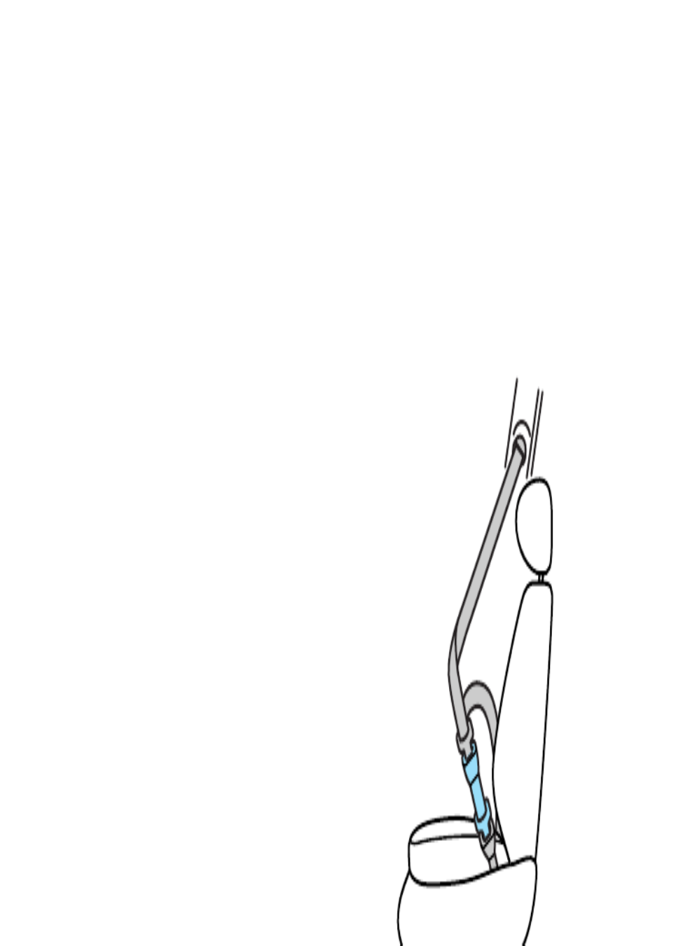
Automatic locking mode
In this mode, the shoulder belt is
automatically prelocked; however,
the belt will react to remove any
slack in the shoulder belt.
The automatic locking mode is not
available on the driver’s safety belt.
When to use the automatic
normal retractor mode which locks
the belts in response to vehicle
movement. For example, if the
driver brakes suddenly, turns a
corner sharply or your vehicle
receives an impact of 8 km/h
(5 mph) or more the combination
safety belts will lock to help reduce
the forward movement of the
driver and passengers.
The retractor can be made to lock
by pulling sharply on the belt.

Canceling automatic locking
mode
Disconnect the combination lap
and shoulder belt and allow it to
completely retract. This will cancel
the automatic locking mode and
activate the vehicle sensitive
safety seat in any passenger seat.
1. Buckle the combination lap and
shoulder belt.
2. Grasp the shoulder belt portion
and pull downward until the entire
belt is extracted.
3. Allow the belt to retract. As the
belt retracts, you will hear a
clicking sound. This indicates that
the safety belt is now in the
automatic locking mode.

To lower the height of the shoulder
belt:
1. Push the control down.
2. Slide down.
To raise the height of the shoulder
belt:
1. Slide up.
2. Pull down on the height adjuster
to make sure that it is locked in
place.
height adjuster so that the
belt rests across the middle of
your shoulder. Be sure the
shoulder belt is properly
positioned on your shoulder each
time you use the belt. If the
shoulder belt is off your shoulder,
on your upper arm or neck, there
is a greater risk of severe injury in
a collision.

S f t b lt i di t li ht d
been unbuckled, pull the belt
steadily from the reel and insert
the small tongue into the small
buckle until a distinct “click” is
heard.
This buckle should be left buckled
except when the seatback is folded
down and cargo that might damage
the seatbelt or get it dirty is being
hauled.
Pull the seat belt across the hips
and insert the big (sliding) tongue
into the appropriate buckle until a
distinct “click” is heard.
Should the center rear belt need to
be unlatched from its anchorage, a
thin probe is required to be
inserted into the hole located on
the underside of the floor mounted
buckle. If the buckle and tongue
are not reconnected, then the belt
is not safe to be used.
Safety belt extension assembly
The safety belt may be too short
even when fully extended.
Approximately 20 cm (8 inches)
may be added to the length of the
belt with a safety belt extension
(part number 611C22). Safety belt
extensions are available at no cost
from your dealer.
Only use extensions manufactured
by the same supplier as the safety
belt. Manufacturer identification is
turned to on, the safety belt
indicator illuminates for
1-2 minutes and the warning chime
sounds for 4-8 seconds.
If the driver safety belt is buckled
while the indicator light is
illuminated and the reminder
chime is sounding, the safety belt
indicator light and reminder turn
off.

security of the anchorage points
and the locking action of the inertia
reels by giving each belt a sharp
tug.
Belts subjected to strain, as in the
result of an accident, should be
replaced and the anchorages
checked by your dealer or a
qualified technician.
Failure to follow these
instructions will affect the
performance of the safety belts
and increase the risk of personal
injury.
Safety belt warning label
A warning label has been placed on
the buckle of each of your vehicle’s
front seat safety belts.
In a collision of sufficient severity
while the safety belt is in use, the
safety belt buckle will pull out of
h l h ll f h
WARNING Replace buckle
assembly if this vehicle is in a collision
or if any orange portion of this label
is visible. (See Owner Guide). Failure
to replace this buckle assembly under
the above conditions could result in
severe personal injuries in the event
of collision.
AVERTISSEMENT Remplacer
l'ensemble de boucle de ceinture en
cas de collision avec ce véhicule, ou si
la partie orange de cette étiquette
est visible (Voir le Guide du
proprietare). Faute de remplacer cet
ensemble de boucle, des blessures
graves pourraient être encourues en
cas de collision.

Important supplemental
restraint system (SRS)
precautions
The supplemental restraint system
(SRS) is designed to:
• work with the safety belt to
protect the driver and right front
passenger.
• reduce certain upper body
injuries.
AIR BAG SUPPLEMENTAL
RESTRAINT SYSTEM (SRS)

When installing forward-
Children and air bags
For additional important safety
information, read all information on
safety restraints in this guide.
Children should always wear safety
belts. Failure to follow these
instructions may increase the risk
of injury in a collision.
Do not attempt to service,
repair, or modify the air bag
Supplemental Restraint System
(SRS) or its fuses. See your Ford
or Lincoln-Mercury dealer.
to co tact t a at g a
bag.

The SRS is designed to activate
when the vehicle is in a collision,
similar to hitting a fixed barrier
head-on at 12-24 km/h (8-14 mph).
The fact that the air bags did not
inflate in a collision does not mean
that something is wrong with the
system. Rather, it means the forces
were not of the type sufficient to
cause activation.
The air bags inflate and deflate
rapidly upon activation.
After air bag deployment, it is
normal to notice a smoke-like,
powdery residue or smell the
burned propellant. This may
consist of cornstarch, talcum
powder (to lubricate the bag), or
sodium compounds (e.g., baking
soda) that result from the
combustion process that inflates
the air bag. Small amounts of
sodium hydroxide may be present,
which may irritate the skin and
eyes, but none of the residue is
toxic.

The SRS consists of the following:
• driver and passenger air bag
modules (which include the
inflators and air bags),
• one impact and one safing
sensor,
• a readiness light and secondary
warning light, and
• the electrical wiring and
components.
The diagnostic module monitors its
own internal circuits and the
supplemental air bag electrical
system readiness (including the
If the air bag is inflated, the
air bag will not function
again and must be replaced
immediately. If the air bag is not
replaced, the unrepaired area will
increase the risk of injury in a
collision.
at o .

the instrument cluster or a
secondary warning light to indicate
the condition of the system. Refer
to the section inAir bag readiness
the chapter.Instrumentation
Routine maintenance of the air bag
is not required.
A difficulty with the system is
indicated by one or more of the
following:
• The readiness light will either
flash or stay lit.
• The readiness light will not
illuminate after ignition is turned
on.
• The air bag secondary warning
light will flash five times. The
pattern will repeat periodically
until the problem or the readiness
light is repaired.
If any of these things happen, even
intermittently, have the SRS
serviced at your dealership or by a
qualified technician immediately.
Unless serviced, the system may

equipped vehicles, see your local
dealership or a qualified technician.
Air bags MUST BE disposed of by
qualified personnel.

child safety seat manufacturer)
should always wear safety belts.
Follow all the important safety
restraints and air bag precautions
that apply to adult passengers in
your vehicle.
If the shoulder belt portion of a
combination lap and shoulder belt
can be positioned so it does not
cross or rest in front of the child’s
face or neck, the child should wear
the lap and shoulder belt. Moving
the child closer to the center of the
vehicle may help provide a good
shoulder belt fit.
If the shoulder belt cannot be
properly positioned:
• move the child to one of the
seats with a lap belt only (if
equipped).
OR
• if the child is the appropriate
size, restrain the child in a safety
seat.

positioning booster seat that is
labelled as conforming to all federal
motor vehicle safety standards.
Belt-positioning booster seats raise
the child and provide a shorter,
firmer seating posture and better
fit of lap and shoulder belts on the
child. A belt-positioning booster
seat should be used if the shoulder
belt rests in front of the child’s face
or neck, or if the lap belt does not
fit snugly on both thighs, or if the
thighs are too short to let the child
sit all the way back on the seat
cushion when the lower legs hang
over the edge of the seat cushion.
You may wish to discuss the special
needs of your child with your
pediatrician.

All built-in child restraints,
including seats, buckles,
retractors, seat latches, interlocks,
and attaching hardware should be
inspected by a qualified dealer
technician after any collision.
The rear seat may include a built-in
child seat. This child seat conforms
to all federal and local motor
vehicle safety standards. Read the
labels located on the child seat
cushion and shoulder belt for
information on the built-in child
seat.
Use the built-in child seat only if
the child is at least one year old,
weighs 10-27 kg (22-60 lbs) and
the child’s shoulders fit below the
shoulder harness slots on the built-
in child seat.
Children not meeting these
requirements should be secured in
an aftermarket seat. Refer to Child
safety seats in this chapter.

Built-in child seat retractors
The belts on built-in child seats are
equipped with a retractor. The
retractor will automatically snug
the belts around the child. If the
belts do not remain snug, take the
vehicle to your dealer or a qualified
technician for child seat repair. The
belts will not remain snug during a
collision if the retractor is not
functioning properly.
is not placed in the integrated child
seat when the folding seatback is
not securely latched.
It prevents the seatback from being
unlatched while the child seat is in
use. When the child seat is
deployed, the seatback cannot be
released.

4. If connected, squeeze the tabs
on the top and bottom of the chest
clip and pull the halves apart to
open the chest clip. Then release
the lower half of belt by pressing
the red button.
5. Place the child in the child seat
and position the shoulder belts
over each shoulder.
child seat.

If both tongues do not latch
in the buckle, do not use the
child seat. See your dealer for
repairs.
7. Fasten both halves of the chest
clip below the child’s shoulders and
adjust it to comfortably hold the
shoulder belts in place on the
child’s chest. The color green must
appear in the indicator window
when fastened.
8. Pull the lap portion of the belts
toward you to make sure the crotch
safety belt buckle is properly
fastened and the retractor is
tongue is inserted first). Insert the
other tongue. The color green must
appear in the indicator window on
each tongue when buckled. Allow
belts to retract and fit snugly.

included with the safety seat you
put in your vehicle. If you do not
install and use the safety seat
properly, the child may be injured
in a sudden stop or collision.
Ford recommends the use of a
child safety seat having a top tether
strap. Install the child safety seat in
a seating position which is capable
of providing a tether anchorage.
For more information on top tether
straps see Attaching safety seats
with tether straps in this chapter.
When installing a child safety seat:
• Use the correct safety belt
buckle for that seating postion.
• Make sure the tongue is securely
fastened in the buckle.
• Keep the buckle release button
pointing up and away from the
safety seat, with the tongue
between the child seat and the
release button, to prevent
accidental unbuckling.

1. Position the child safety seat in a
seat with a combination lap and
shoulder belt.
2. Pull down on the shoulder belt
and then grasp the shoulder belt
and lap belt together.
3. While holding the shoulder and
lap belt portions together, route
h h h h hild
When using forward-facing
child seats move the
passenger seat as far back from
the instrument panel as possible.
Never secure rear-facing infant
seats in the front seat.

5. To put the retractor in the
automatic locking mode, grasp the
shoulder portion of the belt and
pull downward until all of the belt
is extracted and a click is heard.
6. Allow the belt to retract. The
belt will click as it retracts to
i di i i i h i
is latched securely by pulling on it.

tether hook into the hole in the
tongue of the center rear lap belt.
After the hook is in the hole, pull
on the loose end of the lap belt
webbing to shorten the belt and
tighten the tether strap.
To install a tethered child safety
seat in the rear seat, you will need
tether anchor hardware.
Tether anchor hardware
Tether anchor hardware kits (part
Tighten the anchor
according to specifications.
Otherwise, the safety seat may not
be properly secured and the child
may be injured in a sudden stop or
collision.

Starting
105
IMPORTANT VENTILATION
INFORMATION
If the engine is idling while the
vehicle is stopped in an open area
for long periods of time, open the
windows at least 2.5 cm (1 inch).
OFF PLN/FLR
PANEL
A/C
FLOOR
DEF
FLR
DEF
MAX
A/C
Adjust the heating or air
conditioning to bring in fresh air.
Do not start your vehicle in a
closed garage or in other
enclosed areas. Exhaust fumes
can be toxic. Always open the
garage door before you start the
engine. See Guarding against
exhaust fumes in this chapter for
more instructions.

Driving
131
Follow these guidelines to ensure
safe towing procedure:
• Stay within your vehicle’s load
limits.
• Thoroughly prepare your vehicle
for towing. Refer to Preparing to
tow in this chapter.
• Use extra caution when driving
while trailer towing. Refer to
Driving while towing a trailer in
this chapter.
• Service your vehicle more
frequently if you tow a trailer.
Refer to the severe duty schedule
in the maintenance guide and or
service guide.
• Do not tow a trailer until your
vehicle has been driven at least
800 km (500 miles).
• Refer to the instructions
included with towing accessories
for the proper installation and
adjustment specifications.
Produktspezifikationen
| Marke: | Mercury |
| Kategorie: | Auto |
| Modell: | Mystique (1999) |
Brauchst du Hilfe?
Wenn Sie Hilfe mit Mercury Mystique (1999) benötigen, stellen Sie unten eine Frage und andere Benutzer werden Ihnen antworten
Bedienungsanleitung Auto Mercury

17 August 2024
15 August 2024
11 August 2024
11 August 2024
11 August 2024
8 August 2024
8 August 2024
6 August 2024
23 Mai 2024
19 Januar 2024
Bedienungsanleitung Auto
- Auto Mitsubishi
- Auto Cadillac
- Auto Pioneer
- Auto Hyundai
- Auto Tesla
- Auto Citroën
- Auto Skoda
- Auto Chevrolet
- Auto Jaguar
- Auto Peugeot
- Auto Mercedes-Benz
- Auto Acme
- Auto BMW
- Auto Honda
- Auto Infiniti
- Auto Audi
- Auto Jeep
- Auto Smart
- Auto Ford
- Auto Lexus
- Auto Volkswagen
- Auto Volvo
- Auto Toyota
- Auto Genesis
- Auto Kia
- Auto Porsche
- Auto Opel
- Auto Nissan
- Auto Suzuki
- Auto Seat
- Auto Subaru
- Auto RAM
- Auto Mini
- Auto Land Rover
- Auto Mazda
- Auto Dacia
- Auto Vauxhall
- Auto Buick
- Auto Renault
- Auto Fiat
- Auto Alfa Romeo
- Auto MG
- Auto Saturn
- Auto Dodge
- Auto DS
- Auto Lancia
- Auto Maserati
- Auto POLARIS
- Auto Polestar
- Auto Saab
- Auto Sharper Image
- Auto GEM
- Auto Chrysler
- Auto Pontiac
- Auto Lincoln
- Auto Rover
- Auto Tata
- Auto Acura
- Auto GMC
- Auto Mahindra
- Auto Scion
- Auto Lada
- Auto VDL
- Auto Abarth
- Auto Chery
Neueste Bedienungsanleitung für -Kategorien-

3 Dezember 2024
30 November 2024
30 November 2024

16 Oktober 2024

16 Oktober 2024

16 Oktober 2024

15 Oktober 2024

15 Oktober 2024

15 Oktober 2024
15 Oktober 2024