IPX DDK-1700BC Bedienungsanleitung
IPX
Überwachungskamera
DDK-1700BC
Lesen Sie kostenlos die 📖 deutsche Bedienungsanleitung für IPX DDK-1700BC (108 Seiten) in der Kategorie Überwachungskamera. Dieser Bedienungsanleitung war für 18 Personen hilfreich und wurde von 2 Benutzern mit durchschnittlich 4.5 Sternen bewertet
Seite 1/108

INSTALLATION &
OPERATION MANUAL
DDK-1700BC
Fixed Indoor/Outdoor IP Bullet Camera

2
Table Contentsof
SAFETY PRECAUTIONS ............................................................................. 4
1. DESCRIPTION .......................................................................................... 6
1.1 PHYSICAL DESCRIPTION ..................................................................... 6
1.2 HE ESET UTTONT R B ............................................................................ 7
1.3 ALARM WIRING DIAGRAM ...................................................................... 9
GND ............................................................................................................... 9
1.4 HE FUNCTIONT USB .......................................................................... 10
2. INSTALLATION ......................................................................................11
2.1 ARDWARE NSTALLATIONH I .................................................................. 11
2.2 DDK-1700BC B IP ULLET AMERAC .... ERROR OOKMARK NOT DEFINED! B .
2.3 LACING A ESICCANT P D PACK NSIDE THE I DDK-1700BC ...................... 11
2.4 PDATING YSTEM OFTWAREU S S ........................................................... 13
3. Network Configuration .......................................................................... 14
3.1 ABLE ONNECTIONSC C ........................................................................ 14
3.1.1 -1700BC to Computer connection DDK ....................................................................... 14
3.1.2 -1700BC to Network Switch (INTRANET) DDK ........................................................ 14
3.2 ETWORK ETTINGS ONFIGURATIONN S C ................................................ 15
3.2.1 Enabling DHCP Function ............................................................................................. 15
3.2.2 Setting an IP Address ................................................................................................... 15
3.3 OMMUNICATION OFTWARETCP/IP C S ................................................. 16
3.4 NSTALLATIONTCP/IP I ........................................................................ 18
3.5 CONFIGURATION SETTINGTCP/IP ....................................................... 19

3
3.6 ONNECTION ESTINGC T ....................................................................... 20
4. Operating Instructions for Software and Network Connection ........ 23
4.1 EB ROWSERW B ................................................................................. 24
4.1.1 Connecting the K-1700BC DD ..................................................................................... 24
4.1.2 Live Video ................................................................................................................... 25
4.1.3 Setup ............................................................................................................................ 28
4.2 HE T CMS (CENTRAL ANAGEMENT YSTEMM S ) ..................................... 74
4.2.1 Introduction .................................................................................................................. 74
4.2.2 Installing CMS on your Computer ............................................................................... 75
4.2.3 Login ............................................................................................................................ 76
4.2.4 Operation ..................................................................................................................... 78
5. ADVANCED OPERATION ...................................................................... 89
6. SPECIFICATIONS ................................................................................... 92
7. Client System Requirements ................................................................ 94
APPENDIX 1. How to run -1700BC UPnP – DDK ......................................95
APPENDIX 2. Register as a DDNS member – Error! Bookmark not defined.

4
SAFETY PRECAUTIONS
Please read the following safety and operational instructions carefully to prevent harm or injury to
the operator.
WARNING
To prevent fire or shock, avoid exposing this unit to moisture.
Do not block ventilati openings. on
Never spill liquid of any kind on the camera
Do not attempt to service the DDK-1700BC yourself. Opening the -1700BCDDK ’s
enclosure may expose the user to electrical shock. Please refer all servicing to
your reseller.
Do not use liquid cleaners or aerosols for cleaning.

5
6
1. DESCRIPTION
1.1 PHYSICAL DESCRIPTION
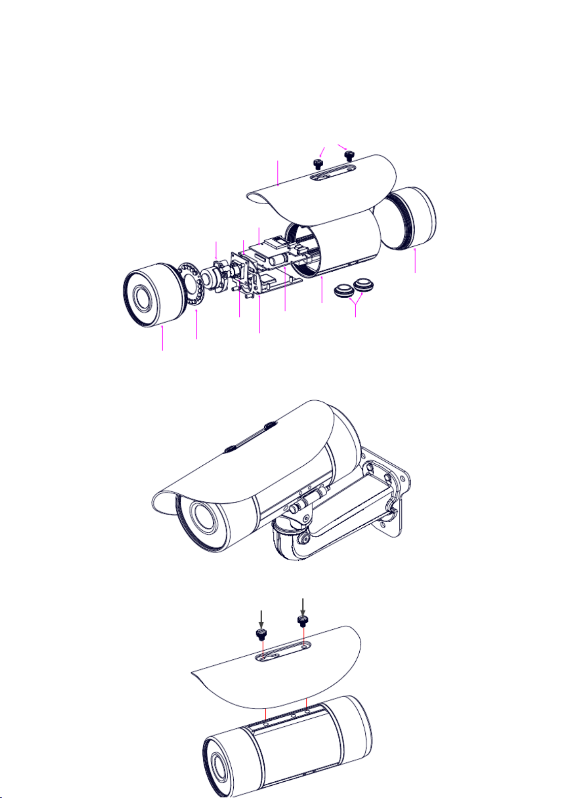
The component parts ( the internal view ).
Dismantle the bullet IP camera to see its different parts. The picture here shows you the internal
component items making up the product.
SCREWS
SUN SHIELD
SD PCB
LENS FAN
FRONT CASE
IR PCB
SENSOR PCB
PCB PLATE
POWER PCB
MIDDLE CASE
WATERPROOF RUBBER
REAR CASE
Camera with bracket ( the external view ).
The picture here shows the camera's exterior, with the bracket screwed in and fixed to it. The
bracket enables you to easily mount the camera on a wall, turned at the angle you want.
NOTE: Use the 2 screws to screw the sun shield (above) into the 2 extreme holes indicated
in the bullet camera (below) to get an unobstructed viewing angle.
Please don’t use the middle hole in the camera, as that will block the view.
7
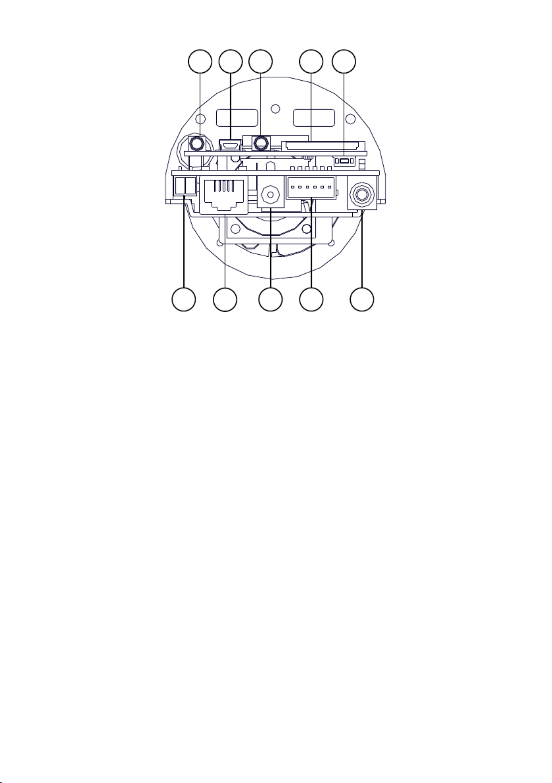
The PCB board:
123 4 5
6 7 8 9 10
1. Power Input: AC 24V input that connects to an external power supply.
2. ETHERNET 10/100 Connector: Standard RJ-45 connector for 10/100 Mbps Ethernet
networks. PoE (Power over Ethernet) function: Provides power to the device via the same
cable as used for the network connection.
3. Plug Inlet: DC 12V inlet that connects to an external power supply.
4. GPIO: 6-PIN connector including Digital output/input, DC output GROUND and for
connecting with external devices.
5. VIDEO OUT Connector: Connector providing composite video output.
6. AUDIO IN: Connector to receive audio input from external devices.
7. USB port: Connects DDK-1700BC to USB port on a PC.AUDIO OUT: Provides audio to an
external device.
8. SD/ SDHC CARD slot: Used for updating system software and archiving video.RESET:
Reset to factory default. (Refer to section 4 The Reset Button.)2.
1.2 The Reset Button
The will bring the DDK-1700BC back to its factory default settings. Press the Reset Button Reset
Button for about 10 seconds. A Blue screen will be displayed and a text that says “RESETTING…”
will appear. The device will then auto reboot. All settings will then be back to default. The following
items will return back to default.
[SETUP]
Network Setup
a. LAN Settings (You can manually reset this function.)
b. PPPOE Settings (You can manually reset this function.)
Dynamic DNS

8
a. DYNAMIC DNS SETTING (You can manually reset this function.)
IMAGE SETUP
a. Privacy Mask Setting
b. IMAGE SETTINGS
AUDIO AND VIDEO
a. VIDEO PROFILE 1
b. VIDEO PROFILE 2
c. VIDEO PROFILE 3
d. AUDIO SETTINGS
MOTION DECTION
a. Video Motion setting
TIME AND DATE
a. TIME CONFIGURATION
b. AUTOMATIC TIME CONFIGURATION
c. SET DATE AND TIME MANUALLY
Event Setup
a. Server
b. Media
c. Event
d. Recording
[ADVANCED]
DI and DO
a. DI and DO
b. LED
c. VIDEO OUTPUT
ICR
a. ICR
HTTPS
a. HTTPS
Access List
a. Allow List
b. Deny List

9
1.3 Alarm wiring diagram
DDK-1700BC
GND
12V+
Di -
Di +
Do -
Do +
+12V
+12V

10
1.4 The USB function
The - can provide two separate functions by connecting the - with a PC via DDK 1700D DDK 1700D
the USB connector.
1. Using an SD card as a card reader.
Insert an SD card into the -1700BC then connect to the PC. You may then transfer files DDK and
between the SD card and the PC. Once you've connected your -1700BC to your computer DDK
Windows will detect the connection and ask you what you want to do with the SD card.
2. Using an SD card as a configuration tool.
Before using the USB configuration setting page, remember to remove the SD card or the PC
won’t show this window.
DHCP ON
DHCP OFF
(default)
NOTE: After changing the settings, click the “Apply” button. All changes will be effective
after removing the USB connector.
NOTE: After the IP address has been changed or reset, unplug the network cable and
then plug it in again to make sure the network connection is in normal mode.
Network
Setting

11
2. INSTALLATION
Follow the instructions and the diagram below to set up the system.
NOTE: The DDK-1700BC s Video Out connector can be connected to a monitor with via RCA ’
connection.
When connected you will see information on the monitor screen including the ,
DDK- factory default IP address (192.168.1.168). The - 1700D’s DDK 1700D’s IP
address will only appear if there is a connection between the - and DDK 1700D
another device.
2.1 Hardware Installation
1. If using external power, connect power adapter to the DDK-1700BC.
2. Connect network cable to the DDK-1700BCs RJ45 connection.
3. Confirm the correct network connection status.
4. Enter -1700BCDDK ’s IP address into your browser.
2.3 Placing Desiccant Pack Inside the -1700BC a DDK
The -1700BC comes with desiccant pack which should be placed inside the camera using DDK a
two-sided adhesive tape e desiccant pack is for reducing the moisture and humidity inside the . Th
camera prevents moisture from condensing on the lens or its cover. and
If the user decides to remove the -1700BC cover after more than a few months of e, the DDK us
used desiccant pack should be removed and place replacement pack inside the camera. a
1. Adhere the desiccant pack to the inner side of the -1700BCDDK .
2. Use two-sided adhesive tape to attach the desiccant pack .
3. Reattach the cover of the -1700BC. DDK

17
4. On the General tab, check if the Internet Protocol (TCP/IP) is included in the list. If the
TCP/IP is included, eed to section 3.5. If it is not included, please follow section 3.4 to proc
install the TCP/IP.

18
3.4 TCP/IP Installation
On the General tab of Connection Properties, under “This connection uses the following items”,
click Internet Protocol (TCP/IP). Then click Install Protocol. Select from the network component
type then click Add. Select Microsoft TCP/IP from the network protocol then click . Click OK Close
to return to the Network Connections window.

19
3.5 TCP/IP conguration setting
Click Start > Control Panel > Network Connections.
Select Internet Protocol (TCP/IP), and then click . Properties
Before completing installation to the LAN, make sure the Internet connection works properly.
If you are using a DHCP server, select Obtain an IP address automatically. Any assigned IP
address for the connected -1700BC must be in the same class type as the server. If there is DDK
no DHCP server, please select specify an IP address enter the IP address, subnet mask and
and default gateway of your choosing to your PC. This IP address must be dierent from other
network IP devices but in the same class type.
20
3.6 Connection Testing
With the previous settings, follow the instructions below to ensure whether you have established
the connection successfully.
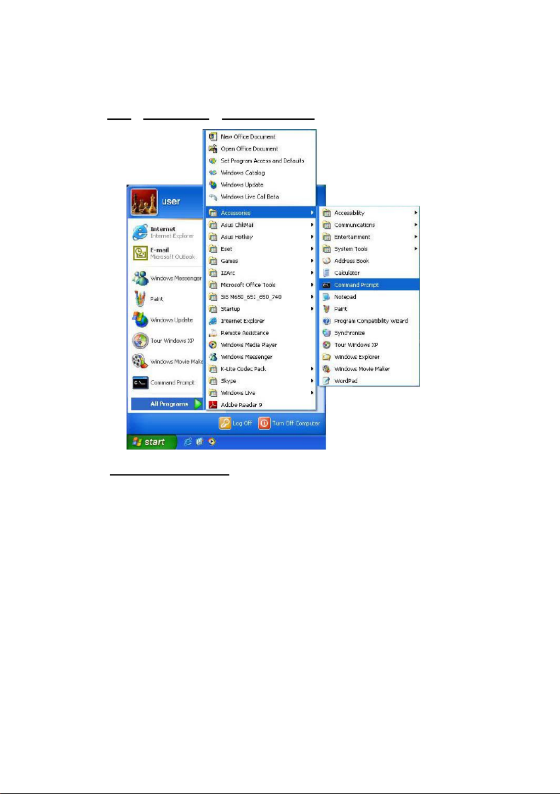
1. Click Start > All Programs > Command Prompt .
2. Enter ping XXX.XXX.XXX.XXX (the -1700BCDDK ’s IP address), then enter. (See the
sample screen below).
** This is the IP address for a -1700BC that is assigned for the connected DDK
DDK-1700BC.

21
If you receive a response as in the screen below, the connection hasn’t been successfully
established. Please re-check all the hardware and software installations by repeating sections
3.4 and 3.5. If you still can’t establish the connection after rechecking, please contact your
dealer.
If you receive a response as in the screen below, you have successfully made the connection.

22

24
4 Web Browser .1
4.1.1 Connecting the -1700BC DDK
1. Start your Web Browser, and then follow the steps below to connect the DDK-1700BC. up
2. Click on the URL at the top of the window. box
3. Enter the URL address of the DDK-1700BC into the URL and press box the “ ”Enter key to
enter the home page.
4. Enter the "User Name" and "Password" in the appropriate spaces.
5. Click on the button to set your entries. “ ”OK
NOTE: The default "User Name" and "Password" are root and Admin, respectively.
NOTE: The page headlined "Enter Network Password shown below” is . Enter the user
name and password of the DDK-1700BC. NOTE: Once authenticated the login ,
page will not appear again unless you close and reconnect.

25
4.1.2 Live Video
Live video from the -1700BC displayed on the home page when your Camera is present DDK is
in your browser. Additional settings provided on the home page. AJAX (default) and the are
ActiveX viewer types display dierent formats on the home page.
The AJAX viewer: Non-IE browsers support (for the JPEG mode only).
Click to change the video resolution and quality. SD card icon:
When a SD card is inserted, the icon becomes red .
Motion-on icon: When motion detection is congured the icon will appear in the right
upper corner.. When motion detection is triggered the icon will blink red .
Recording Status icon: Th icon appears upper right corner. When recording the icon is
becomes . red
Alarm on-icon: Detects external alarms. When alarm is triggered the icon will blink an
red .

26
ActiveX viewer:
Select from the thumbnail options for taking snapshots, setting- a Storage Folder, selecting up
Full Screen mode, Recording, Listening, Talking and Zooming.
Snapshot: Click the button to take snapshot. The icon will change to a blue color a
working properly. when
Set Storage Path: Click on the button to set a storage folder for saving snapshots
and video clips.
Full Screen: Click the button to enter full screen m . The icon will change to a blue ode
color working properly. when
Record Button: Click the button to record a video clip. The icon will change to a blue
color working properly. when
Audio Button: Click the button to start/stop the audio-in function (listen/stop listening).
The icon will change to a blue color working properly. when
Talk Button: Click the button to start/stop audio out function (talk/stop talking). The

27
icon will change to a blue color working properly when
Digital output: Click the button to start/stop digital output. The icon will change to a
blue color working properly. when
Zoom: Click the button to bring up a popup “ ”Zoom window. The icon will change to a
blue color working properly. M e the scrollbar right or left to zoom in or zoom when ov
out on the Live View and the red “Active Frame will be reduced or enlarged. You can drag ”
the Active Frame to a desired position to see the detail of the live image. “ ”
EPTZ Digital Zoom mode. Th mode utilizes the megapixel resolution of the is
DDK-1700BC to simulate the functions of a mechanic PTZ camera. When the digital al
zoom mode is active, the image can be zoomed in and out.
Hold down the left key of your mouse and move to the desired locati in the Global View on
area. As the mouse moves, the live view area shows the corresponding image until the
border of the image appears.
Live Video: Click to go back to the device s homepage. ’
Setup: Click to proceed to the advanced settings.
Logout: Click to . Logout

28
4.1.3 Setup
Click the Setup button o the home page to access advanced settings. n
4.1.3.1 Wizard
For quick conguration, click Wizard at the top of the Setup pages.
This wizard will guide you through a step- -step process to congure your -1700BC. by DDK
Click to continue. Next
Step 1:
The -1700BC default setting is DHCP Use DHCP protocol if DHCP is supported on your DDK On.
LAN. T -1700BC will obtain an IP address automatically from the DHCP server. he DDK
Alternatively you can turn the DHCP congure the -1700BC with a static IP address. O to DDK
The -1700BCDDK ’s default IP is If your Internet Service Provider has provided 192.168.1.168.
connection settings, or you wish to set a static address within your network, enter the information
for your static IP settings .
Click continue. Next to

29
Step 2:
If using PPPoE, select Enable and enter user name and password. Otherwise select Disable and
click to continue. Next
Step 3:
If using a Dynamic DNS account, select Enable and enter your host information.
Click to continue. Next
30
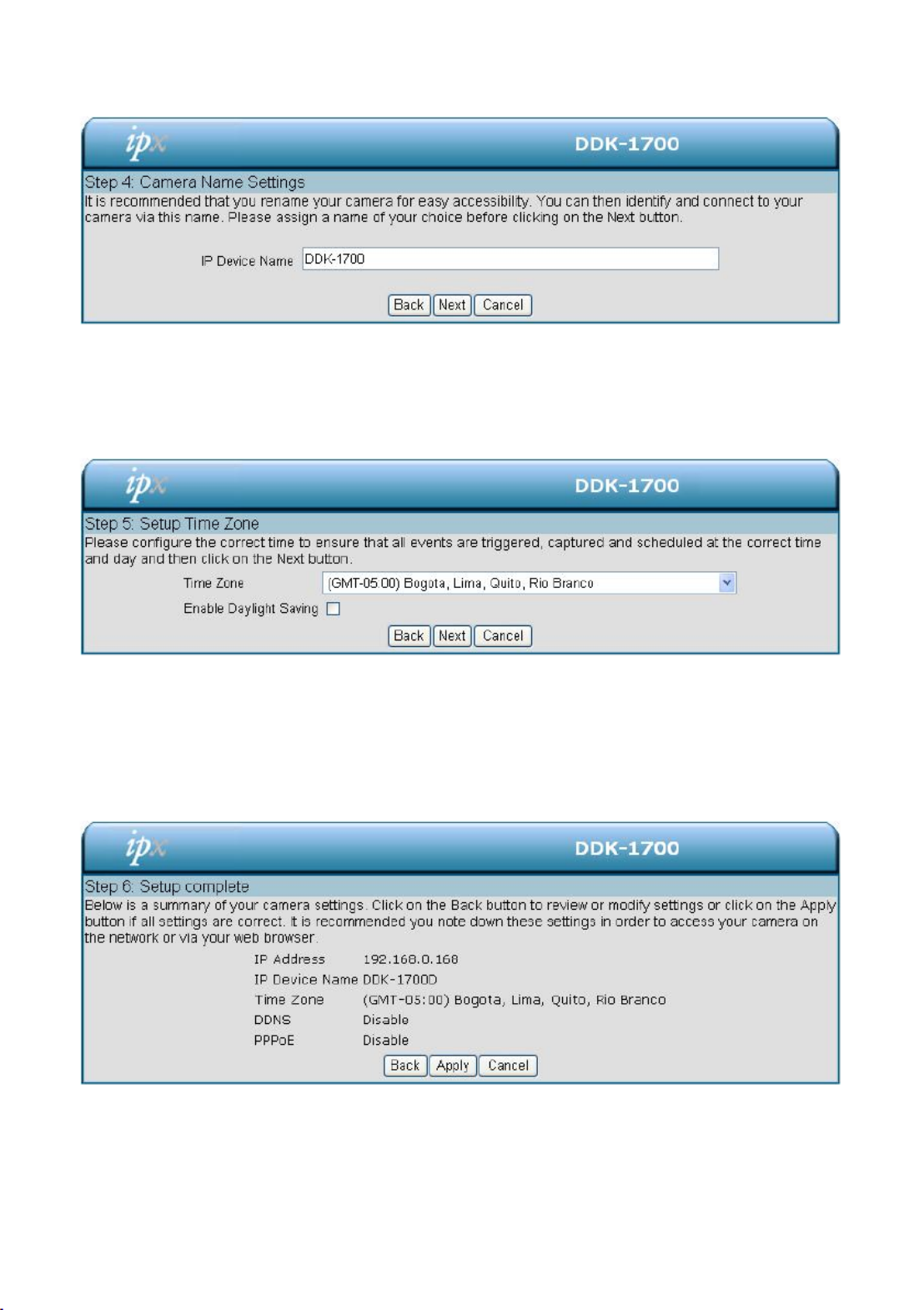
Step 4:
Enter a name for your -1700BC and click to continue. DDK Next
Step5:
Select a time zone to ensure that all events will be triggered, captured and scheduled at the correct
time. Click to continue. Next
Step 6:
If DHCP is selected, a summary of the -1700BCDDK ’s settings will be displayed. Write down all
this information as it is to access the camera over the network. needed
Click Apply to save settings.

31
4.1.3.2Change Image Settings
Follow the steps below to change the cameras video settings. A preview of the image will be shown
in the Live Video window. . Click Submit to activate and save changes.
The Image Setup setting page
1. Click the Image button to enter the image-setting page.
2. VIEWER TYPE. Select AJAX“ ” “ ” or ActiveX mode.
3. . Includes AGCIMAGE SETTINGS “ ” “, Exposure Time“, “Mirror White Balance”, “Flip”, “ ”,

32
“ ” “ ” “Brightness , Contrast , Saturation Sharpness . ”and “ ”
4. DEVICE SETTINGS. Includes Device Name and Timestamp “ ” “ ”.
checkmark the box to activate th function. Click “Enable OSD” and is
Enter "Timestamp Label".
Enter "Timestamp Location".
5. Click the button to submit new image settings Submit
Functions:
AGC
Automatic gain control is abbreviated AGC. Automatic gain control is a
feature where the amount of gain is adjusted automatically based upon the
strength of the incoming signal. Weaker signals receive more gain;
stronger signals receive less gain or none at all.
Exposure Time
Exposure time is controlled in a DDK-1700BC by shutter speed and the
illumination level by the lens aperture. This option allows the user to
choose the exposure time of the DDK-1700BC between “ ” “ “Auto , 1/2000 ,
“ “ “1/1500 , 1/1000 , 1/750 1/500 1/250 1/120 1/60 1/30 1/15“ “ ”, “ ”, “ ”, “ ”, “ ”, “ ”, “ ”,
“ ” “ ”1/7.5 , 1/4 1/2 . and “ ”
Mirror:
Reverses image display
Flip:
To ip the - 0BCDDK 170 ’s image 180 degrees.
White Balance
White balance corrects unnatural color shades.. Select your tions fromop
“ ” “Auto , Outdoor Indoor”, “ ” “ ” and Fluorescent .
Brightness:
Setting to compensate for backlighting
Contrast:
Controls color intensity/strength.
Saturation:
Controls the strength of colors from black and white to bold.
Sharpness
S s clarity of detail in images.et
Timestamp Location:
Click to choose location
Submit:
Click to save settings.

34
4. Select 50 Hz or 60Hz Power.
5. Click on the Submit button to save settings.
Functions:
Mode:
Choose the video format from H.264, JPEG or MPEG4 compression.
Frame size:
Set video resolution
Viewer window area:
Sets Live Viewer resolution
Intra Frame Period:
Setting for compression frequency between frames
Maximum frame rate:
Sets number of frames per second
Video quality:
Sets video stream to constant bit rate or constant quality
Audio Settings:
Switches microphone on/off and adjusts volume.
Encoding:
Setting for type of audio encoding
Audio Mechanism Setting:
Check to activate this function and select MIC or Line In.
Enable audio out:
Check to activate this function and set the Audio out volume level.
Power Line
Select 50 Hz or 60Hz.
NOTE:
Audio In/Out:
Follow the steps.
1. Connect -1700BC through browser. DDK
2. Ensure “Audio Mechanism Setting” & “Enable audio out” are both selected. Click Submit.
3. Connect Mic to the PC, and connect the DDK-1700BC Audio out to the speaker.
4. Select “Talk” ; speak to the PC-connected microphone.
5. Conrm audio from connected speaker.
6. Connect Mic to -1700BC Audio in; connect speaker to PC AUDIO Out. DDK -- --
7. Click “Listen” in the webpage the Mic will send an audio signal to the ;
DDK-1700BC.
8. Conrm audio from PC speaker.
35
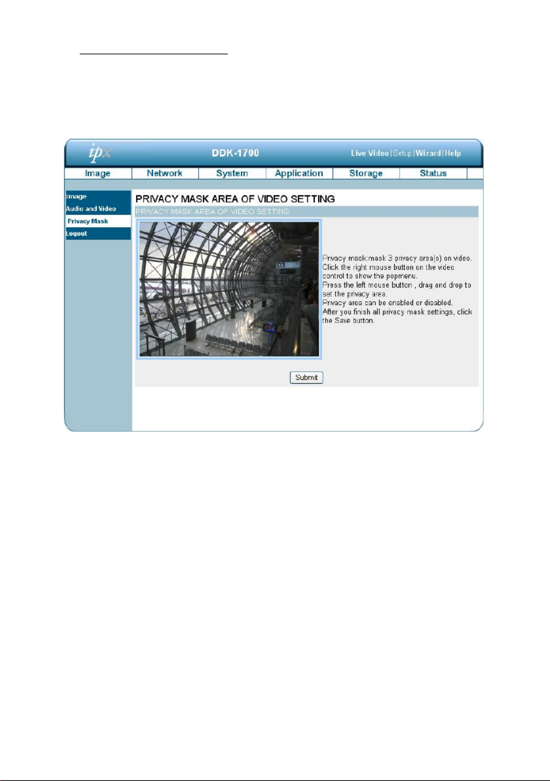
The Privacy Mask settings page
Click on the Privacy Mask button to enter the Privacy Mask Area setting page. Mask up to 3
privacy areas on the displayed video to specify e areas on the -1700BC's image to be th DDK
blocked/excluded from recordings and snapshots.
1. Use the right mouse button on video control to show the pop-menu.
2. Use the left mouse button drag and drop to set the privacy area. and
3. A privacy area can be enabled or disabled.
4. Click the Submit button.

36
4.1.3.3 Changing the Network Settings
Follow the steps below to change the network settings. Set network options and IP address.
1. Click on the Network button the home page to enter the Network Setup page. on
2. The accessible network protocols are PPPoE Port Detail Trac“ ”, “ ”, ” ” “, Dynamic DNS HTTPS ”, “ ”
and ” ”Access List .
3. Input your network setting details. Click the Submit button to save settings.
Functions:
DHCP:
Enables DHCP for dynamic IP address assignment.
DNS
( Domain Name System) is an Internet service that The
translates domain names into IP addresses (e.g., 192.168.0.20).
An address can be obtained from your ISP or network gateway.
Enable UPnP Presentation:
Enable this setting to allow your -1700BC to be congured DDK
as a UPnP device your network. on
Enable UPnP port forwarding:
Enable this setting to allow the -1700BC to add port DDK
forwarding entries into your router automatically.
Changing the PPPoE Network Setting.
The Network page has a PPPoE icon the upper left. Follow the steps below to change the PPPoE .
setting.

38
Changing the Network Settings Port Detail. —
The “Network page has a ” “Port Detail icon at the upper left. This allows you to specify and reserve ports ”
for both HTTP and RSTP streaming. Follow the steps below to change the Port Detail settings.
1. Click on the Port Detail button on the upper left menu to enter the Port Detail page. “ ”
2. Enter the HTTP port and the Access name for stream for the MJPEG streams. “ ” “ ”
3. Enter the HTTPS port . The default value is 443. “ ”
4. Enter the RSTP port and the Access name for stream for the MJPEG or JPEG “ ” “ ”
streams.
5. Click the button to save the new settings. Submit
NOTE: To use an RTSP player to access the -1700BC, use the following RTSP URL DDK
command to request transmission of the streaming data.

39
Functions
HTTP Port
HTTP ports allow you to connect to the DDK-1700BC via a standard web
browser. This port can be set to a number other than the default HTTP port
80. A corresponding port must be opened on the router. For example, if the
port is changed to 8080, users must type in the web browser
'http://192.168.0.100:8080'
HTTPS Port
The HTTPS Port connects the DDK-1700BC with a PC via a secure web
browser.
RTSP Port
This port number used for RTSP streaming to mobile devices, such as is
mobile phones or PDAs. You may specify the address of a particular
stream. For example, live1.sdp can be accessed at
rtsp://x.x.x.x/video1.sdp where the x.x.x.x represents the IP address of
your -1700BC. DDK
NOTE: To view the MPEG4 streaming media Players that support RTSP streaming, such as
Quick Time Player, Real Player, can be used to view the MPEG4 streaming media.
(1) Launch the RTSP player.
(2) Choose , and Open URL dialog box will pop up. “File”an “ ”
(3) Enter an Internet URL to open. The address format is rtsp://<ip address>:<rtsp
port>/<RTSP streaming access name for stream1 stream2 or stream3> ,
(4) The live video will be displayed in your player.

40
Changing the Network Settings —Network Trafc.
The Network page has a “ ” “Traffic” icon at the upper left Specifying the maximum download/upload .
bandwidth for each socket is useful when connecting your device to a busy or heavily loaded network.
Please follow the steps below to change the setting through the network.
1. Click on the Trac button on the upper left menu to enter the Trafc page. “ ”
2. Enter the Maximum Upload Bandwidth and the Maximum Download Bandwidth . “ ” “ ”
3. Click on the Submit button to save the new settings.
Description of function keys:
Maximum Upload Bandwidth:
Enter a range from 0 to 102400. in
Maximum Download Bandwidth:
Enter in a range from 0 to 102400.
Submit:
Click to save settings.

41
Changing the Network Settings — DDNS.
The DDNS (Dynamic Domain Name Server) will use a DNS host name and synchronize it with the
public IP address of the router when it changes. A user name and password are required when using
a DDNS service. On the “Network page click the icon at the upper left of page follow the ” “DDNS”and
steps below to change the DDNS setting s.
1. Click on the Dynamic DNS button on the upper left menu to enter the Dynamic DNS page. “ ”
2. Check the Enable DDNS box “ ” to activate th function. is
3. Fill in the dynamic “Server Address Host Name User Name Password Verify Password”, “ ”, “ ”, “ ”, “ ”,
“Timeout”, “IP Address” and “Email Address”.
4. Click the button to save the settings. Submit
NOTE: Please refer to section 4.1.3.8 (PPPoE & DDNS) for more details.

42
Functions
Enable DDNS Function:
Check to activate th function. is
DNS
(The Domain Name System) is an Internet service that translates domain
names into IP addresses (i.e. 192.168.0.20). The address can be
obtained from your ISP or network gateway.
Server Address:
Select your Dynamic DNS provider from the pull down menu or enter the
server address manually.
Host Name:
Enter the host name of the DDNS server.
User name:
Enter your user name or e-mail used to connect to the DDNS
Password:
Enter your password used to connect to the DDNS server.
Verify Password
Enter your password again to connect to the DDNS server.
Timeout:
Enter the DNS Timeout values for registering the IP address.
Status:
Indicate the connection status, automatically determined by the system.
Produktspezifikationen
| Marke: | IPX |
| Kategorie: | Überwachungskamera |
| Modell: | DDK-1700BC |
Brauchst du Hilfe?
Wenn Sie Hilfe mit IPX DDK-1700BC benötigen, stellen Sie unten eine Frage und andere Benutzer werden Ihnen antworten
Bedienungsanleitung Überwachungskamera IPX

24 August 2024
24 August 2024
Bedienungsanleitung Überwachungskamera
- Überwachungskamera Samsung
- Überwachungskamera Approx
- Überwachungskamera Belkin
- Überwachungskamera Sanyo
- Überwachungskamera Exibel
- Überwachungskamera Gembird
- Überwachungskamera Genius
- Überwachungskamera Hama
- Überwachungskamera LogiLink
- Überwachungskamera Logitech
- Überwachungskamera Manhattan
- Überwachungskamera Nedis
- Überwachungskamera Niceboy
- Überwachungskamera Philips
- Überwachungskamera Sony
- Überwachungskamera Trust
- Überwachungskamera Panasonic
- Überwachungskamera Clas Ohlson
- Überwachungskamera Profile
- Überwachungskamera ZyXEL
- Überwachungskamera Bosch
- Überwachungskamera Laserliner
- Überwachungskamera Buffalo
- Überwachungskamera Canon
- Überwachungskamera Velleman
- Überwachungskamera Powerfix
- Überwachungskamera Eminent
- Überwachungskamera Linksys
- Überwachungskamera Maginon
- Überwachungskamera Netgear
- Überwachungskamera Technaxx
- Überwachungskamera Alecto
- Überwachungskamera Denver
- Überwachungskamera EMOS
- Überwachungskamera Gira
- Überwachungskamera König
- Überwachungskamera MarQuant
- Überwachungskamera Renkforce
- Überwachungskamera Thomson
- Überwachungskamera Trevi
- Überwachungskamera Blaupunkt
- Überwachungskamera Schneider
- Überwachungskamera Trebs
- Überwachungskamera Pyle
- Überwachungskamera Topcom
- Überwachungskamera Pioneer
- Überwachungskamera JVC
- Überwachungskamera Motorola
- Überwachungskamera Xiaomi
- Überwachungskamera Abus
- Überwachungskamera Avidsen
- Überwachungskamera Elro
- Überwachungskamera EZVIZ
- Überwachungskamera Imou
- Überwachungskamera INSTAR
- Überwachungskamera Megasat
- Überwachungskamera Olympia
- Überwachungskamera Smartwares
- Überwachungskamera Switel
- Überwachungskamera Yale
- Überwachungskamera Ferguson
- Überwachungskamera Orion
- Überwachungskamera Gigaset
- Überwachungskamera Strong
- Überwachungskamera Toshiba
- Überwachungskamera Garmin
- Überwachungskamera Perel
- Überwachungskamera Netis
- Überwachungskamera Lindy
- Überwachungskamera Fenton
- Überwachungskamera Waeco
- Überwachungskamera Acme
- Überwachungskamera Burg Wächter
- Überwachungskamera Marmitek
- Überwachungskamera Marshall
- Überwachungskamera Honeywell
- Überwachungskamera B/R/K
- Überwachungskamera Marshall Electronics
- Überwachungskamera TRENDnet
- Überwachungskamera Targa
- Überwachungskamera First Alert
- Überwachungskamera AVerMedia
- Überwachungskamera Zebra
- Überwachungskamera TP-Link
- Überwachungskamera Flamingo
- Überwachungskamera Kodak
- Überwachungskamera Rollei
- Überwachungskamera IGet
- Überwachungskamera Adj
- Überwachungskamera Netatmo
- Überwachungskamera Duramaxx
- Überwachungskamera Ebode
- Überwachungskamera Xavax
- Überwachungskamera InFocus
- Überwachungskamera Overmax
- Überwachungskamera Monoprice
- Überwachungskamera Monacor
- Überwachungskamera JUNG
- Überwachungskamera Ednet
- Überwachungskamera AG Neovo
- Überwachungskamera Nest
- Überwachungskamera Edimax
- Überwachungskamera V-TAC
- Überwachungskamera Aritech
- Überwachungskamera Uniden
- Überwachungskamera Kogan
- Überwachungskamera Genie
- Überwachungskamera M-e
- Überwachungskamera Elmo
- Überwachungskamera Lumens
- Überwachungskamera Jablocom
- Überwachungskamera Conceptronic
- Überwachungskamera D-Link
- Überwachungskamera Eufy
- Überwachungskamera Stabo
- Überwachungskamera Friedland
- Überwachungskamera EVOLVEO
- Überwachungskamera SPC
- Überwachungskamera August
- Überwachungskamera Ring
- Überwachungskamera Digitus
- Überwachungskamera SereneLife
- Überwachungskamera Swann
- Überwachungskamera Vitek
- Überwachungskamera DataVideo
- Überwachungskamera LevelOne
- Überwachungskamera Aida
- Überwachungskamera APC
- Überwachungskamera Beafon
- Überwachungskamera Chuango
- Überwachungskamera Cisco
- Überwachungskamera Grandstream
- Überwachungskamera Delta Dore
- Überwachungskamera EVE
- Überwachungskamera Defender
- Überwachungskamera Tenda
- Überwachungskamera Swisstone
- Überwachungskamera Foscam
- Überwachungskamera Ubiquiti Networks
- Überwachungskamera Kramer
- Überwachungskamera Vaddio
- Überwachungskamera Intellinet
- Überwachungskamera Reolink
- Überwachungskamera Swan
- Überwachungskamera Hikvision
- Überwachungskamera FLIR
- Überwachungskamera Furrion
- Überwachungskamera Arlo
- Überwachungskamera Nexxt
- Überwachungskamera Planet
- Überwachungskamera EnGenius
- Überwachungskamera Dörr
- Überwachungskamera Lorex
- Überwachungskamera Ikan
- Überwachungskamera Comtrend
- Überwachungskamera Somfy
- Überwachungskamera Dahua
- Überwachungskamera Dedicated Micros
- Überwachungskamera DIO
- Überwachungskamera EasyN
- Überwachungskamera Escam
- Überwachungskamera EverFocus
- Überwachungskamera Ganz
- Überwachungskamera GeoVision
- Überwachungskamera Hombli
- Überwachungskamera Home Protector
- Überwachungskamera Iiquu
- Überwachungskamera Indexa
- Überwachungskamera Interlogix
- Überwachungskamera KlikaanKlikuit
- Überwachungskamera Kompernass
- Überwachungskamera Mr Safe
- Überwachungskamera Naxa
- Überwachungskamera Nordval
- Überwachungskamera Notifier
- Überwachungskamera Oplink
- Überwachungskamera Provision ISR
- Überwachungskamera Quantum
- Überwachungskamera Raymarine
- Überwachungskamera Revo
- Überwachungskamera SAB
- Überwachungskamera Satel
- Überwachungskamera SecurityMan
- Überwachungskamera Sinji
- Überwachungskamera SMC
- Überwachungskamera Sonic Alert
- Überwachungskamera Sricam
- Überwachungskamera Steren
- Überwachungskamera Storage Options
- Überwachungskamera Tenvis
- Überwachungskamera Hive
- Überwachungskamera Ubiquiti
- Überwachungskamera Vivotek
- Überwachungskamera Woonveilig
- Überwachungskamera Y-cam
- Überwachungskamera ACTi
- Überwachungskamera AVer
- Überwachungskamera Epcom
- Überwachungskamera ZKTeco
- Überwachungskamera AirLive
- Überwachungskamera Mobotix
- Überwachungskamera Dahua Technology
- Überwachungskamera Speco Technologies
- Überwachungskamera 3xLOGIC
- Überwachungskamera Atlantis Land
- Überwachungskamera CRUX
- Überwachungskamera Pentatech
- Überwachungskamera Summer Infant
- Überwachungskamera Illustra
- Überwachungskamera Surveon
- Überwachungskamera Avigilon
- Überwachungskamera Brilliant
- Überwachungskamera Hanwha
- Überwachungskamera Lanberg
- Überwachungskamera Verint
- Überwachungskamera Axis
- Überwachungskamera EtiamPro
- Überwachungskamera MEE Audio
- Überwachungskamera Advantech
- Überwachungskamera Chacon
- Überwachungskamera Alula
- Überwachungskamera EKO
- Überwachungskamera IOIO
- Überwachungskamera KJB Security Products
- Überwachungskamera BZBGear
- Überwachungskamera Adesso
- Überwachungskamera Brickcom
- Überwachungskamera Insteon
- Überwachungskamera Aigis
- Überwachungskamera Pelco
- Überwachungskamera ORNO
- Überwachungskamera Atlona
- Überwachungskamera Linear PRO Access
- Überwachungskamera Laxihub
- Überwachungskamera Valueline
- Überwachungskamera Aqara
- Überwachungskamera Tecno
- Überwachungskamera Lutec
- Überwachungskamera Brinno
- Überwachungskamera Night Owl
- Überwachungskamera WyreStorm
- Überwachungskamera Exacq
- Überwachungskamera Equip
- Überwachungskamera AVMATRIX
- Überwachungskamera UniView
- Überwachungskamera Alfatron
- Überwachungskamera Syscom
- Überwachungskamera BLOW
- Überwachungskamera Videotec
- Überwachungskamera DSC
- Überwachungskamera AViPAS
- Überwachungskamera Milestone Systems
- Überwachungskamera Inkovideo
- Überwachungskamera Hamlet
- Überwachungskamera Mobi
- Überwachungskamera Infortrend
- Überwachungskamera VideoComm
- Überwachungskamera Kguard
- Überwachungskamera Boyo
- Überwachungskamera HiLook
- Überwachungskamera Mach Power
- Überwachungskamera Canyon
- Überwachungskamera Digital Watchdog
- Überwachungskamera Ernitec
- Überwachungskamera Ikegami
- Überwachungskamera Gewiss
- Überwachungskamera Weldex
- Überwachungskamera Costar
- Überwachungskamera Sentry360
- Überwachungskamera ALC
- Überwachungskamera Spyclops
- Überwachungskamera Compro
- Überwachungskamera IDIS
- Überwachungskamera I3International
- Überwachungskamera B & S Technology
- Überwachungskamera Qian
- Überwachungskamera Accsoon
- Überwachungskamera Control4
- Überwachungskamera Petcube
- Überwachungskamera Apeman
- Überwachungskamera ATN
- Überwachungskamera IC Intracom
- Überwachungskamera POSline
- Überwachungskamera Watec
- Überwachungskamera ETiger
- Überwachungskamera Videcon
- Überwachungskamera BirdDog
- Überwachungskamera Topica
- Überwachungskamera Rostra
- Überwachungskamera Caddx
- Überwachungskamera Whistler
- Überwachungskamera ClearView
- Überwachungskamera Beseye
- Überwachungskamera IMILAB
- Überwachungskamera CNB Technology
- Überwachungskamera Tapo
- Überwachungskamera Securetech
- Überwachungskamera NetMedia
- Überwachungskamera Nivian
- Überwachungskamera Guardzilla
- Überwachungskamera Blink
- Überwachungskamera Zavio
- Überwachungskamera Campark
- Überwachungskamera Annke
- Überwachungskamera AVTech
- Überwachungskamera Vimtag
- Überwachungskamera Security Labs
- Überwachungskamera Seneca
- Überwachungskamera Vosker
- Überwachungskamera Owltron
- Überwachungskamera Enabot
- Überwachungskamera Luis Energy
- Überwachungskamera Sir Gawain
- Überwachungskamera VisorTech
- Überwachungskamera Milesight
- Überwachungskamera GVI Security
- Überwachungskamera Conbrov
- Überwachungskamera HuddleCamHD
- Überwachungskamera Setti+
- Überwachungskamera BIRDFY
- Überwachungskamera I-PRO
- Überwachungskamera DVDO
- Überwachungskamera TCP
Neueste Bedienungsanleitung für -Kategorien-
15 Oktober 2024

15 Oktober 2024
14 Oktober 2024
14 Oktober 2024

13 Oktober 2024
13 Oktober 2024
13 Oktober 2024
11 Oktober 2024
11 Oktober 2024
11 Oktober 2024