Honeywell FocusBT MS1633 Bedienungsanleitung
Honeywell
Barcode-Leser
FocusBT MS1633
Lesen Sie kostenlos die 📖 deutsche Bedienungsanleitung für Honeywell FocusBT MS1633 (52 Seiten) in der Kategorie Barcode-Leser. Dieser Bedienungsanleitung war für 20 Personen hilfreich und wurde von 2 Benutzern mit durchschnittlich 4.5 Sternen bewertet
Seite 1/52

METROLOGIC INSTRUMENTS, INC.
MS1633 FocusBT
™ with
Bluetooth® Wireless Technology
Area Imaging Bar Code Scanner
Installation and User’s Guide

Copyright
© 2008 by Metrologic Instruments, Inc. All rights reserved. No part of this
work may be reproduced, transmitted, or stored in any form or by any means
without prior written consent, except by reviewer, who may quote brief
passages in a review, or provided for in the Copyright Act of 1976.
Trademarks
Metrologic is a registered trademark of Metrologic Instruments, Inc.
Products identified in this document are hereby acknowledged as
trademarks, registered or otherwise, of Metrologic Instruments, Inc. or their
respective companies.
The Bluetooth word mark and logos are owned by the Bluetooth SIG, Inc.
and any use of such marks by Metrologic Instruments, Inc. is under license.
Other trademarks and trade names are those of their respective owners.

ii
T C ABLE OF ONTENTS
Introduction
Product Overview ............................................................................................. 1
Scanner and Accessories................................................................................. 2
Scanner Components....................................................................................... 3
Labels............................................................................................................... 4
Maintenance..................................................................................................... 5
Getting Started
Battery Tips and Cautions ................................................................................ 6
Charger Status Indicators................................................................................. 6
Charging the Battery ........................................................................................ 7
Battery Installation............................................................................................ 8
Low Battery Warning ........................................................................................ 8
Removing the Battery for Charging .................................................................. 8
Driver Installation
Driver Installation for USB Adapter with Bluetooth Technology........................ 9
Auto Reconnect Driver Setup ......................................................................... 12
FocusBT Connection Configuration................................................................ 14
Establishing Communication via Bluetooth Technology
When FocusBT Acts as a Server to Other Devices........................................ 16
When FocusBT Acts as a Client to Other Devices ......................................... 17
When FocusBT is Used with an MS9535 Cradle............................................ 18
Range Gate Mode .......................................................................................... 18
Inventory Mode............................................................................................... 19
Stand Kits
Stand Components, MLPN 46-00147............................................................. 20
Hard Mounting the Stand................................................................................ 21
Assembling the Stand .................................................................................... 22

iii
T C ABLE OF ONTENTS
Scanner Operation
Two Default Modes of Operation.................................................................... 23
Audible Indicators........................................................................................... 24
Visual Indicators ............................................................................................. 25
Failure Modes................................................................................................. 26
Depth of Field by Minimum Bar Code Element Width .................................... 27
IR Activation Range........................................................................................ 28
Troubleshooting Guide ....................................................................................... 29
Design Specifications ......................................................................................... 33
Default Settings – Communication Parameters.................................................. 35
Configuration Modes .......................................................................................... 37
Upgrading the Flash ROM Firmware.................................................................. 38
Limited Warranty ................................................................................................ 39
Regulatory Compliance
Safety ............................................................................................................. 40
EMC ............................................................................................................... 41
Patents ............................................................................................................... 43
Index .................................................................................................................. 44
Contact Information and Office Locations........................................................... 46

3
INTRODUCTION
Scanner Components and Charger
Figure 1. Scanner and Charger Components
Item Description
1 Yellow LED See Visual Indicators (on page 25)
2 White LED See Visual Indicators (on page 25)
3 Blue LED See Visual Indicators (on page 25)
4 Speaker See Audible Indicators (on page 24)
5 Trigger
6 Red Window LED Aperture
7 Power Button See Charging the Battery (on page 8)
8 Blue Power LED See Charging the Battery (on page 7)
9 Battery Pack See Battery Installation (on page 8)
10 Lock See Battery Installation (on page 8)
11 Power Jack See Battery Installation (on page 8)
12 Charging Contacts See Battery Installation (on page 7)
13 Blue Power LED See Charger Status Indicators (on page 6)
14 White Charge LED See Charger Status Indicators (on page 6)

www.metrologic.com 4
INTRODUCTION
Labels
Each scanner has a label located on the underside of the head. This label
provides the unit’s model number, date of manufacture, serial number, CE and
caution information. The charger, the USB Adapter and the battery also have
labels with important safety and compliance information. The following figure
provides examples of these labels and their locations.
Figure 2. Label Locations and Samples
Caution:
To maintain compliance with applicable standards, all circuits connected to the scanner must
meet the requirements for SELV (Safety Extra Low Voltage) according to EN/IEC 60950-1.
To maintain compliance with standard CSA-C22.2 No. 60950-1/UL 60950-1 and norm
EN/IEC 60950-1, the power source should meet applicable performance requirements for a
limited power source.
www.metrologic.com 6
G SETTING TARTED
Battery Tips and Cautions
Before the FocusBT can be placed in operation the battery pack must be
charged for a minimum of 8 hours. After the initial preparation charge of
8 hours, the battery will only require 6 hours to come to a full charge when it
gives a Low Battery warning (see page 8). Follow the steps on page 7 to fully
charge the battery.
Once charged, the unit is able to handle 5400 continuous first pass readings over
a period of approximately 9 hours. After 30 seconds of no activity the scanner
will go into a sleep mode to conserve battery life.
Caution
Observe proper precautions when handling batteries.
Batteries may leak or explode if improperly handled. Observe the following
precautions when handling batteries for use in this product:
• Be sure the battery is turned off before replacing the battery.
• Be sure the battery is turned off when installed in the charger.
• Use only batteries approved for use in this equipment.
Do not mix old and new batteries or batteries of different types.
• Do not attempt to insert the battery upside down or backwards.
• Do not short or disassemble the battery.
• Do not expose the battery to flame or excessive heat.
• Do not immerse the battery in water or expose it to water.
• Do not transport or store with metal objects such as necklaces or hairpins.
• Batteries are prone to leakage when fully discharged.
To avoid damage to the product, be sure to remove the battery when no
charge remains.
• When not in use store the battery in a cool dry place.
• Discontinue use immediately should you notice any changes in the
battery, such as discoloration or deformation.
• Please recycle used batteries in accordance with local regulations.
Charger Status Indicators
There are two status indicators on the front of the charger located under the
Metrologic Logo. The following table lists how these indicators will illuminate
depending on the status of the charger.
C S B WHARGER TATUS LUE LED (PW) HITE LED (CH)
Charging On Blinking
Fully Charged On Solid
Power On On OFF
Power Off OFF OFF

7
Figure
3
Figure 4
Figure 5
Figure 6
G SETTING TARTED
Charging the Battery
Before the FocusBT can be placed in operation for the first time, the battery
must be charged for a minimum of 8 hours. After the initial preparation
charge of 8 hours, the battery will only require 6 hours to come to a full charge
when it gives a Low Battery warning (see page 8).
1. Check the AC input requirements of the
power supply to make sure the voltage
matches the AC outlet. The outlet
should be located near the charger and
easily accessible.
2. Plug the power supply into the socket
on the back of the charger.
A blue PW will illuminate near the
Metrologic logo indicating the charger is
receiving power.
3. Verify that the battery pack is not ON.
The blue power LED on the battery pack
should be OFF.
Warning!
Damage to the battery pack
can occur if it is charged while
turned ON.
4. Insert the battery pack into the charger
as shown in Figure 5.
A white CH will start to flash on and off
on the charger near the Metrologic logo.
If the white CH does not appear,
check to make sure the battery pack
is seated all the way in the charger
with the battery contacts facing the
contacts on the charger.
5. When the battery is completely
charged the charging indicator
(CH) will stop flashing and stay
illuminated.
www.metrologic.com 8
G SETTING TARTED
Battery Installation
MS1633 FocusBT
is a battery powered scanner.
Before the FocusBT can be
placed in operation for the first time, the battery must be charged for a
minimum of 8 hours.
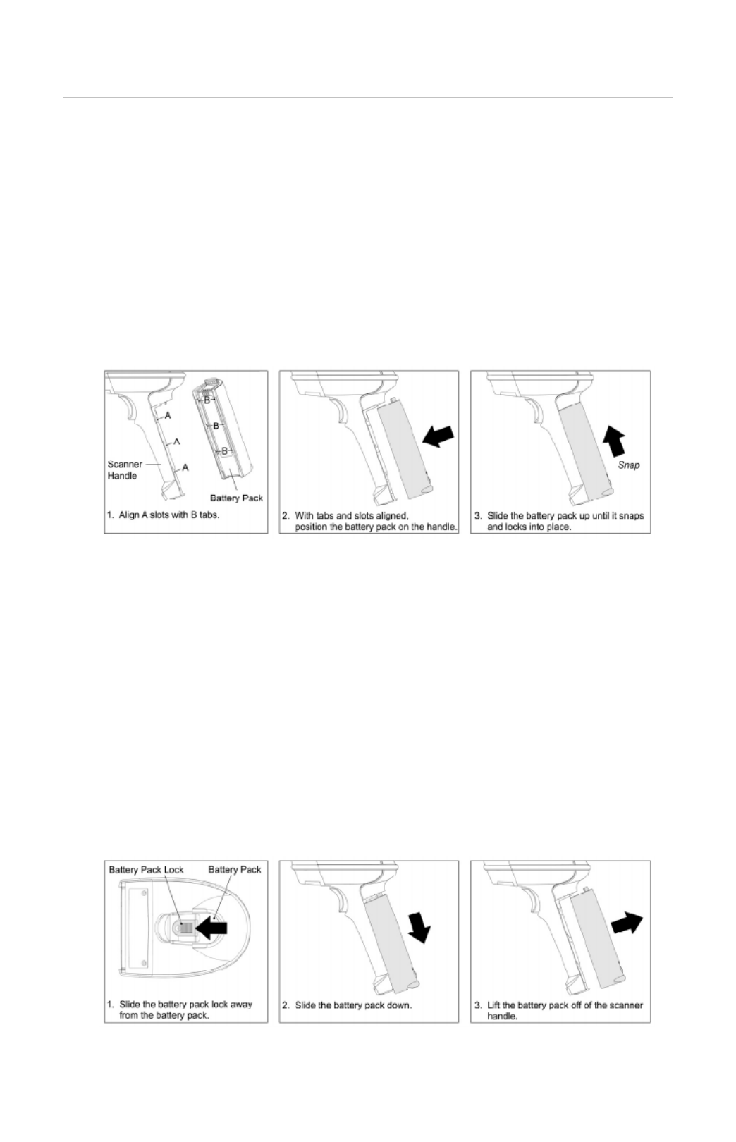
To install the battery:
1. Align the tabs of the charged battery pack with the slots on the scanner’s
handle
2. Then, slide the battery pack up toward the top of the scanner. There will be
a snap when the battery is installed correctly.
Figure 7. Steps for Installing the Battery
Low Battery Warning
When the battery is low the unit will add an additional beep after the good scan
beep
. The additional beep alerts the user
when there is less than 10% of a
charge left on the battery.
Removing the Battery for Charging
In order to charge the battery, it must be disconnected from the scanner.
1. Turn off the battery by pressing the button near the base of the battery.
2. Disengage the lock on end of the scanner handle (see below).
3. Slide the battery pack down away from the head of the scanner.
4. Lift the battery straight off the scanner handle (see below).
Figure 8. Steps for Removing the Battery for Charging

9
D IRIVER NSTALLATION
Driver Installation for USB Adapter with Bluetooth Technology
1. Load the included FocusBT CD into the CD-ROM drive on the
host/computer.
2. If the CD-ROM does not automatically open, click on the Window’s Start
button, choose Run, then click Browse to locate and open the CD-ROM
drive. Double-Click on the Metrologic.exe file then click OK.
3. Click on the button to begin installation. MetroBT Driver
Figure 9.
4. Choose a Setup Language then click OK.
Figure 10.

11
D IRIVER NSTALLATION
Driver Installation for USB Adapter with Bluetooth Technology
8. To continue the installation procedure without showing warnings for
unauthorized drivers, select I accept and click OK.
Figure 14.
9. Plug the Bluetooth USB Adapter into the host device then click OK to
indicate the Bluetooth Adapter has been connected.
Figure 15.
10. After the installation completes click on Yes to restart the host
device/computer. The host/computer must be rebooted at this time in order
for the driver to function properly.
Figure 16.
www.metrologic.com 12
D IRIVER NSTALLATION
Auto Reconnect Driver Setup
1. Load the included FocusBT CD into the CD-ROM drive on the
host/computer.
2. If the CD-ROM does not automatically open, click on the Window’s Start
button, choose Run, then click Browse to locate and open the CD-ROM
drive. Double-Click on the Metrologic.exe file then click OK.
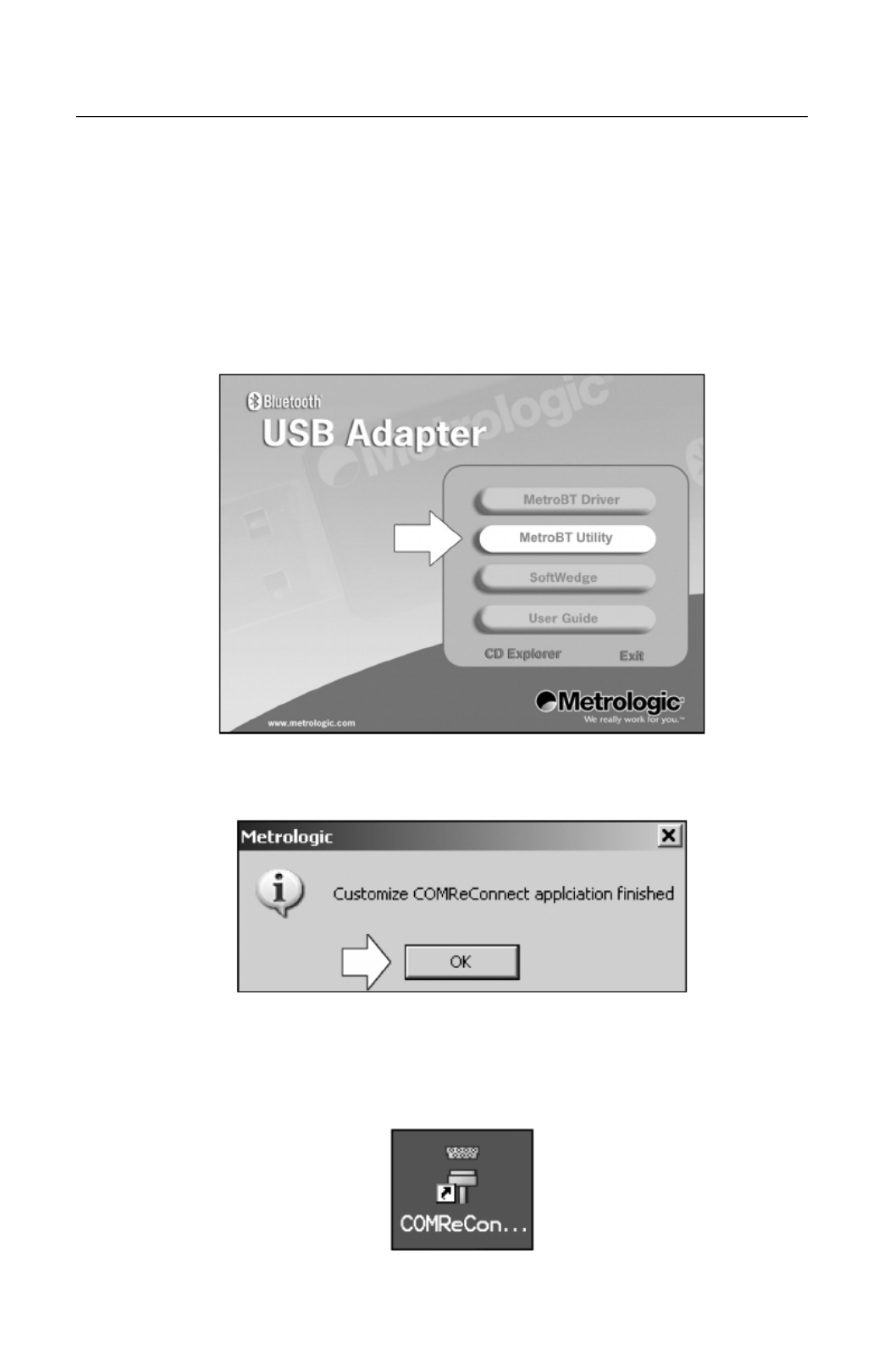
3. Click on the button to begin installation. MetroBT Utility
Figure 17.
4. Click OK to continue.
Figure 18.
5. Locate the COMReConnect icon on the Windows desktop and double click
to open the program.
Figure 19.

13
D IRIVER NSTALLATION
Auto Reconnect Driver Setup
6. The Auto Reconnect Utility will automatically start if any of the COM ports
with Bluetooth technology are checked. When running, the utility window will
look like the figure below.
Clicking the “X” in the corner of the window or clicking on the close button
will disable the auto-reconnect feature. However, if the Place icon in the
taskbar option is checked, the utility will remain active after the window is
closed.
Figure 20.

15
D IRIVER NSTALLATION
FocusBT Connection Configuration
4. The final screen of the New Connection Wizard should indicate the virtual
Bluetooth Com port that was setup. This will usually be a high number, as
seen in the screen shot below. Remember this COM number for
application setup.
Click Next to Continue.
Figure 24.
5. After the FocusBT has been added to the connection list, right click on the
icon and select Connect in order to establish a link via Bluetooth technology
between the FocusBT and your computer.
The FocusBT should emit a connection tone and/or the blue light on the top
of the unit should stop blinking, indicating a connection has been
established.
Figure 25.

www.metrologic.com 16
E C TSTABLISHING OMMUNICATION VIA BLUETOOTH ECHNOLOGY
Communication via Bluetooth wireless technology must be established
between the FocusBT and the host device before the FocusBT can be used
for normal operation.
In a network with Bluetooth technology, the FocusBT can operate as a server
(service-provide mode), or as a client.
When FocusBT Acts as a Server to Other Devices with
Bluetooth Technology
FocusBT’s default is to act as a server to other devices with Bluetooth
technology. In this mode, other devices enabled with Bluetooth wireless
technology can initiate a connection to the scanner.
FocusBT can be configured to always accept incoming connection requests and
not require a valid Bluetooth PIN. Alternatively, FocusBT can be configured to
require a valid Bluetooth PIN. In this case, the PIN used by a remote device while
establishing connection to the FocusBT, must match the one previously stored in
FocusBT.
*Bluetooth PIN Not Required Bluetooth PIN Required
³ 124306 ³ 124316
To store a Bluetooth PIN
The FocusBT can be configured to store a Bluetooth PIN so that any remote
device trying to establish a connection with the scanner, must match the stored
PIN before a connection will made. The stored PIN must be numeric and be
between 4 to 16 digits long. A PIN that does not satisfy the criteria will not be
stored.
After scanning the following bar code, the next bar code scanned will be stored
and used as the Bluetooth PIN. This feature is used in conjunction with the
Bluetooth PIN required feature.
Next bar code is Bluetooth PIN
³ 999918
Scanning the Recall Defaults bar code resets the PIN to the default
value of 0000.
17
E C T STABLISHING OMMUNICATION VIA BLUETOOTH ECHNOLOGY
When FocusBT Acts as a Client to Other Devices with
Bluetooth Technology
In the client device mode of operation, the Focus initiates the connection via BT
Bluetooth wireless technology. The Bluetooth address of the remote device is
required to establish a connection. The remote device must also be configured
to accept incoming connections and must support the Bluetooth wireless
technology Serial Port (SPP) profile.
• If the Bluetooth address of the remote device is headed with FNC3
and consists of a 12-digit hex value (e.g. 3000CA7000118), scan the
address bar code to establish the communication.
Sample of a 12-digit Bluetooth Address with FNC3
³ 000CA7000118
• If the Bluetooth address of the remote device is not headed with
FNC3 but is just a common 12-digit hex value (e.g. 000CA7000118),
first scan the Get Bluetooth Address bar code then scan the remote
device’s Bluetooth address bar code.
Get Bluetooth Address
³ 0 0 0 C A 7 F F F F F F
• If the Bluetooth address code of the remote device is set to
000CA7000000, FocusBT will automatically go into server mode and
will not attempt to establish an outgoing connection via Bluetooth
wireless technology.
To return to service mode:
Scan the bar code below to change FocusBT from client mode to
service mode.
*Provide Bluetooth Service
³ 000CA7000000

www.metrologic.com 18
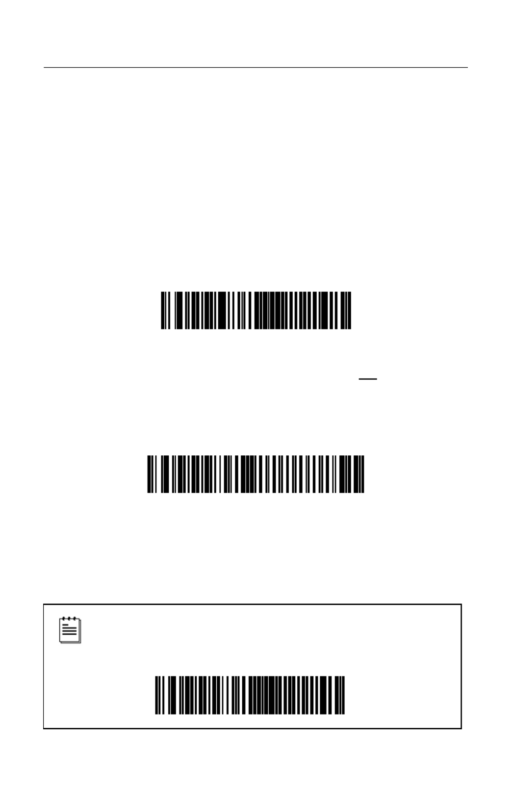
E C T STABLISHING OMMUNICATION VIA BLUETOOTH ECHNOLOGY
When FocusBT is Used with an MS9535 Cradle
FocusBT can be configured to communicate with an MS9535 cradle but it will
require the FocusBT to be configured to use a special communication protocol
used by the MS9535 cradle. Scan the Enable MS9535 Cradle Protocol bar
code below to enable the special communication protocol.
The FocusBT cannot be configured or flash-upgraded via an
MS9535 cradle. Communication settings of the cradle cannot be
changed by scanning configuration bar codes with the FocusBT.
Support for the MS9535 cradle is limited to bar code
transmission.
Do not forget to disable the MS9535 cradle protocol when the
cradle is no longer in use.
Enable MS9535 cradle protocol* *Disable MS9535 cradle protocol
³ 1 2 5 5 1 4 ³ 1 2 5 5 0 4
RangeGate® Mode
The operation range of the communication via Bluetooth technology is at least
10 meters between the scanner and host system. When FocusBT is out of
operation range for Bluetooth technology, the communication link will break and
the blue LED will start to flash on the scanner.
FocusBT can be configured to store scanned bar codes into the non-volatile
memory when the connection for Bluetooth technology is inactive. The scanner
will transmit the bar codes and erase them from memory once the connection for
Bluetooth technology is re-established. The size of the non-volatile memory is
32768 bytes.
Scan the following bar codes to enable or disable Range Gate Mode.
Enable Range Gate *Disable Range Gate
³ 1 2 3 7 0 7 ³ 1 2 3 7 1 7

19
E C T STABLISHING OMMUNICATION VIA BLUETOOTH ECHNOLOGY
Inventory Mode
In Inventory mode, there is a quantity field associated with each bar code.
Similar to RangeGate mode, the data is stored in the scanner’s non-volatile
memory. However, in inventory mode, the data is always stored independent of
whether the connection for Bluetooth technology is active or not, and is not
uploaded automatically until a special bar code is scanned.
For the bar codes associated with this mode, please consult the FocusBT
Supplemental Configuration Guide (MLPN 00-02281A).
RangeGate and Inventory Mode are mutually-exclusive. If both are
enabled, Inventory mode takes priority.

21
S K TAND ITS
Hard Mounting the Stand (Optional)
Metrologic provides two #8 wood screws for securing the stand base to the
counter top. The following figure provides the pilot hole dimensions for securing
the stand base.
Figure 27. Stand Base Hole Pattern (Not to Scale)

www.metrologic.com 22
S KTAND ITS
Assembling the Stand
Figure 28. Assembling the Stand

www.metrologic.com 24
S O CANNER PERATION
Audible Indicators
When the FocusBT is in operation, it provides audible feedback. These sounds
indicate the status of the scanner. Eight settings are available for the tone of the
beep (normal, six alternate tones and no tone). To change the tone, refer to the
MetroSelect Single-Line Configuration Guide (MLPN 00-02544) or MetroSet2’s
help files.
One Beep
When the scanner successfully reads a bar code it will beep once and the
white LED will turn on indicating data is being transmitted.
If the scanner does not beep once and the white light does not turn on, then
the bar code has been successfully read. not
Short Razzberry Tone
This tone is a failure indicator (see Failure Modes on page 26).
Long Razzberry Tone
This tone is a failure indicator (see Failure Modes on page 26).
Three Beeps - At Power Up
When FocusBT first receives power it will start an initialization sequence.
All LEDs (yellow, white, and blue) will light for approximately two seconds then
start to alternately flash. When the scanner has finished initializing the LEDs
will stop flashing and the unit will beep three times indicating that the scanner
is ready for use.
Three Beeps - Configuration Mode
When entering configuratio ll flash while the scanner n mode, the white LED wi
simultaneously beeps three times. The white and blue LEDs will continue to
flash while in this mode. Upon exiting configuration mode, the scanner will
beep three times, and the LEDs will stop flashing.
When configured, three beeps can also indicate a communications timeout
during normal scanning mode.
When using single-code-configuring, the scanner will beep three times:
a normal tone followed by a short pause, a high tone and then a low tone.
This indicates that the single configuration bar code has successfully
configured the scanner.
Low Battery Tone
When the battery is low the unit will add an additional beep after the good scan
beep
. The additional beep alerts the user
when there is less than 10% of a
charge left on the battery.

25
S O CANNER PERATION
Audible Indicators
Low to High Beep
This tone indicates the connection via Bluetooth technology has been made.
High to Low Beep
This tone indicates the connection via Bluetooth technology is disconnected.
A Double Razz Tone
When the communication link for Bluetooth technology is not active, the
scanner will emit a double razz tone and the Blue LED will start to flash. This
can occur when the scanner is out of the communication range for Bluetooth
technology from the host system and the RangeGate feature is disabled.
Visual Indicators
The MS1633 has three LED indicators (yellow, white and
blue) located on the top of the scanner. When the scanner
is on, the flashing or stationary activity of the LEDs
indicates the status of the current scan and the scanner.
No LEDs are Illuminated
The LEDs will not be illuminated if the scanner is not
receiving power from the host or transformer.
The scanner is in stand-by mode. Present a bar code to
the scanner and the blue LED will turn on when the IR
detects the object.
Steady Yellow
The yellow LED is illuminated when the scanner is in the stand.
Steady Blue
The blue LED is illuminated when the scanner is active and linear illumination
is on or when the scanner is attempting to decode a bar code.
Steady Blue and Single White Flash
When the scanner successfully reads a bar code it will beep once and the
white LED will turn on indicating data is being transmitted.
If the scanner does not beep once and the white light does not turn on, then
the bar code has not been successfully read.
Figure 30.

www.metrologic.com 26
S O CANNER PERATION
Visual Indicators
Steady White
When the scanner successfully reads a bar code it will beep once and the
white LED will turn on indicating data is being transmitted.
After a successful scan, the scanner transmits the data to the host
device. Some communication modes require that the host inform the
scanner when data is ready to be received. If the host is not ready to
accept the information, the scanner’s white LED will remain on until the
data can be transmitted.
Alternating Flashing of Blue and White
This indicates the scanner is in configuration mode. A short razzberry tone
indicates that an invalid bar code has been scanned while in this mode.
Flashing Blue
The blue LED will flash if the trigger is pressed while the scanner is in the
in-stand presentation mode. The blue LED will stop flashing after a brief
period of time.
The operation range of communication for Bluetooth wireless technology is
approximately 10 meters between the scanner and host system. If the unit is
out of range, the communication link will break, the blue LED will start to flash,
and the unit will emit a double razz tone. The blue LED will continue to blink
for 30 seconds while the unit is out of rage. If RangeGate or Inventory mode
are not enabled, the scanner will enter sleep mode to conserve battery power
after 30 seconds.
Failure Modes
Long Razzberry Tone – During Power Up
Failed to initialize or configure the scanner. If the scanner does not respond
after reprogramming, return the scanner for repair.
Short Razzberry Tone – During Scanning
An invalid bar code has been scanned when in configuration mode or the
trigger has been pulled too fast.
27
S O CANNER PERATION
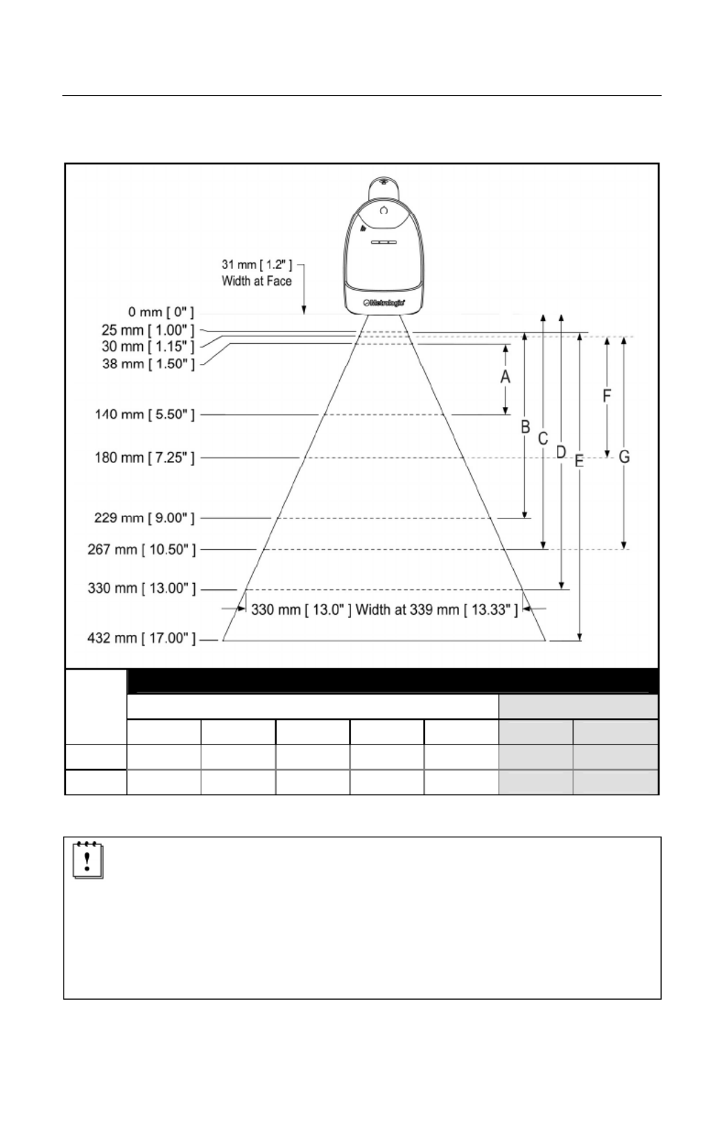
Depth of Field by Minimum Bar Code Element Width
M B C E W INIMUM AR ODE LEMENT IDTH
1D / PDF Data Matrix
A B C D E F G
mm .132 .19 .254 .33 .533 .254 .381
mils 5.2 7.5 10.4 13 21 10 15
Figure 31. Depth of Field by Minimum Bar Code Element Width
Decoding and functional capability of the unit is restricted through the use
of license numbers provided by Metrologic. Units will not support key
features such as, but not limited to, the ability to decode PDF, 2D or OCR
fonts without the proper licenses. Desired licenses can be specified at
the time of sale or call a Metrologic representative for more information.
Standard models ship with the ability to read all 1D, PDF and 2D bar
codes. OCR fonts are disabled by default and must be specifically
requested at an additional cost.
Specifications are subject to change without notice.

www.metrologic.com 28
S O CANNER PERATION
IR Activation Range
The MS1633 has a built in object detection sensor that instantly turns on the
scanner when an object is presented within the scanner’s IR activation area.
Figure 32. IR Activation Area
Specifications are subject to change without notice.

29
T GROUBLESHOOTING UIDE
The following guide is for reference purposes only. Contact a Metrologic
representative at 1-800-ID-Metro or 1-800-436-3876 to preserve the limited
warranty terms.
All Interfaces
MS1633 Series Troubleshooting Guide
Symptoms Possible Causes Solution
No LEDs, beep
or illumination.
No power is being
supplied to the
scanner.
Check to make sure the battery is
turned on.
Check to make sure the battery is
properly installed.
The battery may need to be
charged.
Long Razz tone
on power up.
There has been a
diagnostic failure.
Contact a Metrologic service
representative, if the unit will not
function.
Long Razz tone
when exiting
configuration
mode.
There was a failure
saving the new
configuration.
Re-try to configure the scanner.
Contact a Metrologic Service
Representative if the unit will not
hold the saved configuration.
Long Razz tone.
There is a scanning
mechanism failure.
Contact a Metrologic service
representative.
Short Razz tone
in configuration
mode.
An invalid bar code
has been scanned.
Scan a valid bar code or quit
configuration mode.

www.metrologic.com 30
T GROUBLESHOOTING UIDE
Symptoms Possible Causes Solution
The unit powers
up, but does not
beep when bar
code is scanned.
The beeper is
disabled and no tone
is selected.
Enable the beeper and select a
tone.
The unit powers
up, but does not
scan and/or
beep.
The bar code
symbology trying to
be scanned is not
enabled.
UPC/EAN, Code 39, interleaved 2
of 5, Code 93, Code 128, Codabar
and PDF are enabled by default.
Verify that the type of bar code
being read has been selected.
The unit powers
up, but does not
scan and/or
beep.
The scanner is trying
to scan a bar code
that does not match
the configured
criteria.
Verify that the bar code being
scanned falls into the configured
criteria (i.e. character length lock or
minimum bar code length settings).
The unit scans
a bar code, but
locks up after
the first scan
and the white
LED stays on.
The scanner is
configured to support
some form of host
handshaking but is
not receiving the
signal.
If the scanner is setup to support
ACK/NAK, check to make sure the
host is supporting the
handshaking properly.
The unit scans,
but the data
transmitted to
the host is
incorrect.
The scanner’s data
format does not
match the host
system requirements.
Verify that the scanner’s data
format matches that required by
the host.

31
T G ROUBLESHOOTING UIDE
Symptoms Possible Causes Solution
The bar code may
have been printed
incorrectly.
Check if it is a check
digit/character/or border problem.
The scanner is not
configured correctly
for this type of bar
code.
Check if check digits are set
properly.
The unit beeps
at some bar
codes and NOT
for others of the
same bar code
symbology.
The minimum symbol
length setting does
not work with the bar
code.
Check if the correct minimum
symbol length is set.
The unit scans
the bar code but
there is no data.
The configuration is
not set correctly.
Make sure the scanner is
configured for the appropriate
mode.
The unit scans
but the data is
not correct.
The scanner and host
may not be configured
for the same interface
parameters.
Check that the scanner and the
host are configured for the same
interface parameters.
The unit is
transmitting
each character
twice.
The configuration is
not set correctly.
Increase interscan code delay
setting. Adjust whether the F0
break is transmitted. It may be
necessary to try this in both
settings.
Alpha
characters show
as lower case.
The computer is in
Caps Lock mode.
Enable Caps Lock detect setting
of the scanner to detect if the PC
is operating in Caps Lock.

www.metrologic.com 32
T G ROUBLESHOOTING UIDE
Symptoms Possible Causes Solution
Everything
works except for
a couple of
characters.
These characters
may not be supported
by that country’s key
look up table.
Try operating the scanner in Alt
mode.
The unit powers
up OK and
scans OK but
does not
communicate
properly with the
host.
The USB adapter
may not be
connected properly
Check to make sure the USB
adapter is connected properly.
Characters are
being dropped.
Inter-character delay
needs to be added to
the transmitted output.
Add some inter-character delay to
the transmitted output by using
the Configuration Guides
(MLPN 00-02544 and 00-02065).

33
D S ESIGN PECIFICATIONS
MS1633 DESIGN SPECIFICATIONS
O PERATIONAL
Light Source: LED 645 nm
Pulse Duration: 10 µs to 8000 µs
Maximum Output: 0.76 mW Peak
Depth of Scan Field: 0 mm – 330 mm (0" – 13") for
0.330 mm (13 mil) Bar Code at Default Setting
49 mm W x 19 mm H (1.9" W x 0.8" H) at 20 mm (0.8")
Field of View:
264 mm x 106 mm (10.4" W x 4.2" H) at 280 mm (11.0")
Minimum Bar Width: 0.127 mm (5.0 mil)
Long Range: 0 mm – 203 mm (0" – 8") from Window
Infrared Activation:
Short Range: 0 mm – 101 mm (0" – 4") from Window
Motion Tolerance: 47 cm/sec (18"/sec) 100% UPC in stand
Decode Capability:
Autodiscriminates All Standard 1-D, GS1 Databar,
PDF417, microPDF, MaxiCode, Data Matrix, QR Code,
UCC, EAN Composites, Postals, Aztec
Image Transfer*: BMP, TIFF, or JPEG output
* RS232 and USB only
Print Contrast: 20% Minimum Reflectance Difference
Number Characters Read: Up to 80 Data Characters on 1D;
1850 Text Characters for PDF417
Beeper Operation: 7 tones or no beep
Blue Unit Powered, Ready to Scan
White Good Read
Indicators (LED)
Default Settings:
Yellow In Stand
Decoding and functional capability of the unit is restricted through the
use of license numbers provided by Metrologic. Units will not support
key features such as, but not limited to, the ability to decode PDF, 2D or
OCR fonts without the proper licenses. Desired licenses can be
specified at the time of sale or call a Metrologic representative for more
information. Standard models ship with the ability to read all 1D, PDF
and 2D bar codes. OCR fonts are disabled by default and must be
specifically requested at an additional cost.
Specifications are subject to change without notice.

35
D S – C P EFAULT ETTINGS OMMUNICATION ARAMETERS
Many functions of the scanner can be “configured” – that is, enabled or disabled.
The scanner is shipped from the factory configured to a set of default conditions.
The default parameter of the scanner has an asterisk (*) in the charts on the
following pages. If an asterisk is not in the default column then the default setting
is OFF or DISABLED.
PARAMETER PARAMETER DEFAULT DEFAULT
Multi-Try Trigger Out-of-Stand * Data Matrix
Presentation Mode In-Stand * QR Code
Continuous Trigger Maxicode
Single Trigger Aztec
Aiming in
Trigger and Continuous Modes * Postals
Aiming in Presentation Mode Mod 43 Check on Code 39
Long-Range In-Stand * MSI-Plessy 10/10 Check Digit
Short-Range In-Stand MSI-Plessy Mod 10 Check Digit *
Long-Range Out-of-Stand * Paraf Support ITF
Short-Range Out-of-Stand ITF Symbol Lengths Variable
RangeGate Mode Symbol Length Lock None
Inventory Mode Beeper tone Normal
UPC/EAN * Beep/transmit sequence Before
transmit
Code 128 * Communication timeout None
Code 93 * Razzberry tone on timeout
Codabar * Three beeps on timeout
Interleaved 2 of 5 (ITF) * Same symbol rescan timeout:
1000 msecs *
MOD 10 check on ITF
Code 11
Same symbol rescan timeout
configurable in 50 msec steps
(maximum of 6.35 sec.)
Code 39 * No Same symbol timeout
Full ASCII Code 39 Infinite Same symbol timeout
PDF *

www.metrologic.com 36
D S – C P EFAULT ETTINGS OMMUNICATION ARAMETERS
PARAMETER PARAMETER DEFAULT DEFAULT
Tab Suffix
Inter-character delay
configurable in 1 msec steps
(maximum of 255 msecs)
1 msecs
10 msecs
in KBW “DE” Disable Command
Number of scan buffers
(maximum) 8 Enable Command
Transmit UPC-A check digit * ACK/NAK
Transmit UPC-E check digit Two Digit Supplements
Expand UPC-E Five Digit Supplements
Convert UPC-A to EAN-13 Bookland
Transmit lead zero on UPC-E 977 (2 digit) Supplemental
Requirement
Transmit UPC-A number system * Supplements are not Required *
Transmit UPC-A Manufacturer ID# * Two Digit Redundancy *
Transmit UPC-A Item ID# * Five Digit Redundancy
Transmit Codabar
Start/Stop Characters Coupon Code 128
CLSI Editing (Enable) † Configurable Code Lengths 7 avail
Transmit Mod 43 Check digit
on Code 39
† Code Selects with configurable
Code Length Locks 3 avail
Transmit Mod 10/ITF Configurable Prefix characters 10
avail
Transmit MSI-Plessy Suffix characters 10
avail
Transmit Sanyo ID Characters Prefixes for Individual Code types
Nixdorf ID Editing
LRC Enabled Function/Control Key Support *
UPC Prefix Omnidirectional Scanning *
UPC Suffix Linear Only Scanning
Carriage Return * Linear 1D / Omni 2D
Tab Prefix
† These options are mutually exclusive. One can not be used in conjunction with
the other.

37
C M ONFIGURATION ODES
The MS1633 FocusBT Series has three modes of configuration.
• Bar Codes
The MS1633 can be configured by scanning the bar codes included in the
Metrologic Single-Line Configuration Guide (MLPN 00-02544). This manual
can be downloaded for FREE from Metrologic’s website
(www.metrologic.com).
• MetroSet2
This user-friendly Windows-based configuration program allows you to
simply ‘point-and-click’ at the desired scanner options. This program can be
downloaded for FREE from Metrologic’s website (www.metrologic.com) or
set-up disks can be ordered by calling 1-800-ID-METRO.
• Serial Configuration
This mode of configuration is ideal for OEM applications. This mode gives
the end-user the ability to send a series of commands using the serial port of
the host system. The commands are equivalent to the numerical values of
the bar codes located in the MetroSelect Single-Line Configuration Guide
(MLPN 00-02544).
Produktspezifikationen
| Marke: | Honeywell |
| Kategorie: | Barcode-Leser |
| Modell: | FocusBT MS1633 |
Brauchst du Hilfe?
Wenn Sie Hilfe mit Honeywell FocusBT MS1633 benötigen, stellen Sie unten eine Frage und andere Benutzer werden Ihnen antworten
Bedienungsanleitung Barcode-Leser Honeywell

6 Oktober 2024
3 Oktober 2024
13 September 2024
28 August 2024
22 August 2024
12 August 2024
8 August 2024
6 August 2024
6 August 2024
6 August 2024
Bedienungsanleitung Barcode-Leser
- Barcode-Leser Approx
- Barcode-Leser Manhattan
- Barcode-Leser Trimble
- Barcode-Leser König
- Barcode-Leser Renkforce
- Barcode-Leser Nilox
- Barcode-Leser Motorola
- Barcode-Leser Olympia
- Barcode-Leser Garmin
- Barcode-Leser Casio
- Barcode-Leser ELO
- Barcode-Leser Datamax-O'neil
- Barcode-Leser Intermec
- Barcode-Leser Zebra
- Barcode-Leser Digitus
- Barcode-Leser HTC
- Barcode-Leser Palm
- Barcode-Leser Deltaco
- Barcode-Leser IFM
- Barcode-Leser Datalogic
- Barcode-Leser DeLOCK
- Barcode-Leser ID-Tech
- Barcode-Leser Steren
- Barcode-Leser Posiflex
- Barcode-Leser Newland
- Barcode-Leser Atlantis Land
- Barcode-Leser Brady
- Barcode-Leser Godex
- Barcode-Leser Socket Mobile
- Barcode-Leser Adesso
- Barcode-Leser Code
- Barcode-Leser Cypress
- Barcode-Leser QUIO
- Barcode-Leser Tecno
- Barcode-Leser Unitech
- Barcode-Leser Argox
- Barcode-Leser CipherLab
- Barcode-Leser Code Corporation
- Barcode-Leser Wasp
- Barcode-Leser Hamlet
- Barcode-Leser EC Line
- Barcode-Leser Vultech
- Barcode-Leser Psion
- Barcode-Leser Bluebird
- Barcode-Leser POS-X
- Barcode-Leser Mach Power
- Barcode-Leser Qoltec
- Barcode-Leser Koamtac
- Barcode-Leser DENSO
- Barcode-Leser Baracoda
- Barcode-Leser Qian
- Barcode-Leser IC Intracom
- Barcode-Leser POSline
- Barcode-Leser ZBA
- Barcode-Leser Opticon
Neueste Bedienungsanleitung für -Kategorien-

30 November 2024
30 November 2024
3 Oktober 2024
23 September 2024
22 September 2024
13 September 2024
12 September 2024
6 September 2024
6 September 2024
6 September 2024