Glemm PM 2 Bedienungsanleitung
Glemm Nicht kategorisiert PM 2
Lies die bedienungsanleitung für Glemm PM 2 (2 Seiten) kostenlos online; sie gehört zur Kategorie Nicht kategorisiert. Dieses Handbuch wurde von 55 Personen als hilfreich bewertet und erhielt im Schnitt 4.0 Sterne aus 6 Bewertungen. Hast du eine Frage zu Glemm PM 2 oder möchtest du andere Nutzer dieses Produkts befragen? Stelle eine Frage
Seite 1/2
21.1
RJ45
METAL
BLACK
200 m
max
Manuale di istruzioni
Articolo:
PM 2
Caratteristiche tecniche
Distanza max da amplicatore200mt con cavo RG45 CAT6
Lunghezza microfono41 cm
Dimensioni base170 x 50 x 152 mm (l x h x p)
Peso0,9 Kg
PRODOTTO DA / PRODUCED BY:KARMA ITALIANA Srl
Via Gozzano 38/bis 21052 Busto Arsizio (VA) - www.karmaitaliana.it
Lo smaltimento del prodotto deve
essere eettuato conferendolo
ad un apposito centro di raccolta
dierenziata (Dir. 2012/19/UE).
Il fabbricante, allo scopo di migliorare i propri prodotti, si riserva il diritto di modicarne le caratteristiche siano
esse tecniche o estetiche, in qualsiasi momento e senza alcun preavviso.
Made in P.R.C.
www.glemm.eu
Il microfono multizona mod. PM 2 è stato progettato per operare in
abbinamento all’amplicatore mod. PAA 720MBZX.
Non collegatelo ad altri amplicatori per evitare possibili danni al microfono o
all’amplicatore stesso.
Questo microfono non necessita di alimentatore esterno in quanto attinge
l’energia necessaria direttamente dall’amplicatore al quale è collegato.
Conservate questo manuale di istruzioni per utilizzi futuri. Ricordatevi che di
vericare la presenza di eventuali aggiornamenti nella scheda prodotto sul
sito www.glemm.eu.
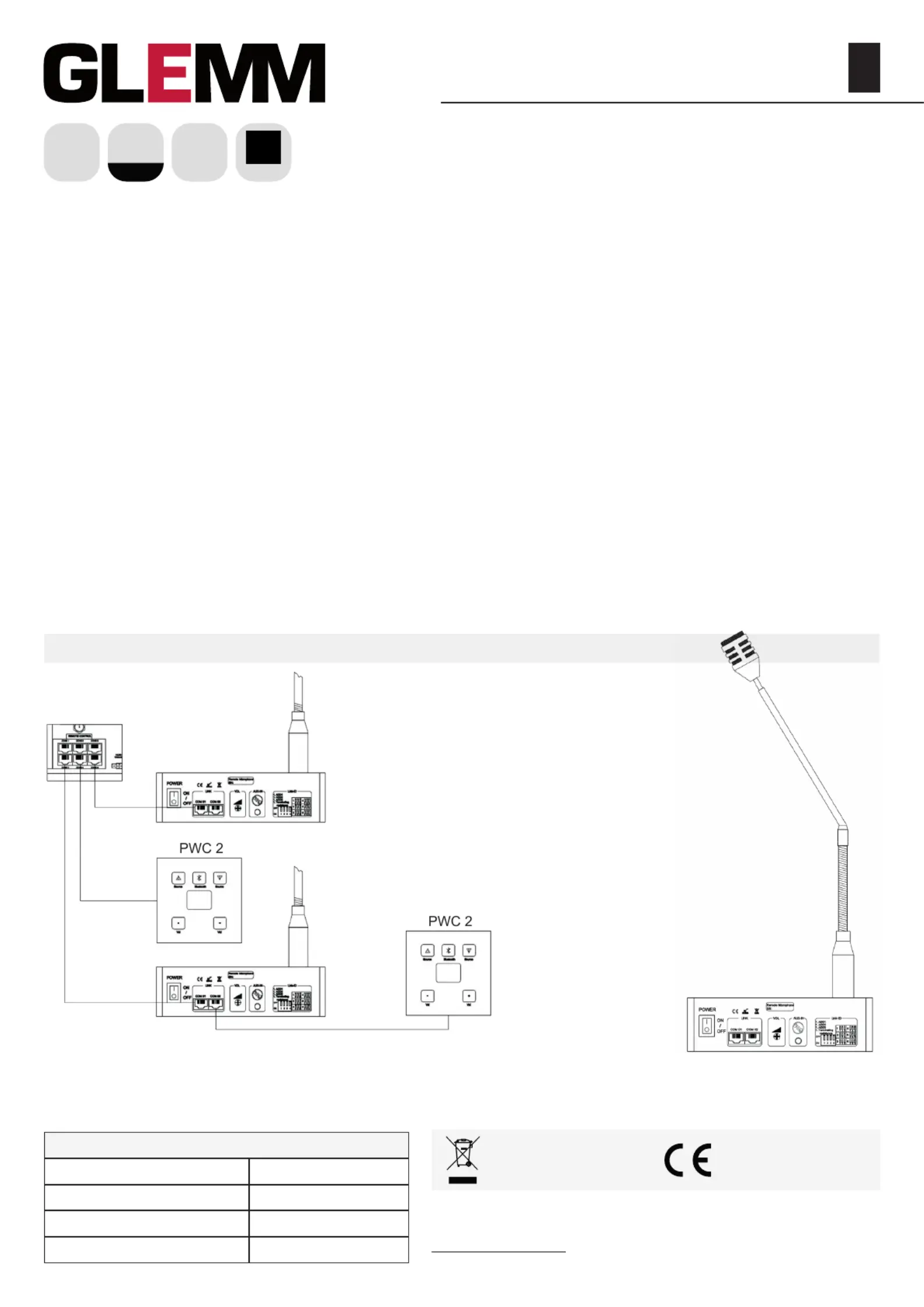
A. Collegamento
Attenzione: tutti i collegamenti e le impostazioni dei Dip switch vanno
eettuate ad amplicatore spento. Per collegare il microfono all’amplicatore
è suciente utilizzare un cavo ethernet RJ 45 sfruttando la porta dedicata
sull’amplicatore. L’amplicatore dispone di 6 prese RJ45, ognuna destinata
ad una specica zona. Il microfono potrà essere collegato in qualunque presa
mentre eventuali moduli di controllo remoto mod. PWC 2 dovranno essere
collegati alla presa della zona che dovranno controllare. Microfono e controller
possono essere collegati a cascata alla stessa presa (il cavo del microfono
sfrutterà la presa COM 01 mentre il pannello PWC 2 andrà collegato alla
presa COM 02).
I microfoni possiedono degli interruttori DIP SWITCH per impostarne la
priorità. La distanza massima tra amplicatore e microfono, utilizzando un
cavo di tipo CAT6, non dovrà superare i 200mt.
Retro del microfonoSchema di collegamento
CAT 6
CAT 6
CAT 6
AMPLIFICATORE
CAT 6
Sul retro del microfono è presente una presa 3,5mm per segnale di tipo AUX.
Ogni microfono avrà la possibilità di inviare a una o più zone il proprio segnale
AUX in alternativa alla voce. Tramite dip switch potete attivare la resistenza di
terminazione utile, quando la distanza dall’amplicatore supera i 10mt.
B. Utilizzo
Accendete l’amplicatore e il microfono (utilizzando il tasto posteriore). Per
inviare un messaggio, cliccate sui tasti delle zone che volete coinvolgere,
premete una volta il tasto CALL e dopo la nota musicale potrete parlare.
Terminato l’annuncio premete nuovamente il tasto CALL. Se desiderate
inviare il messaggio a tutte le zone, premete il tasto ALL prima del tasto CALL.
Durante la trasmissione di un messaggio da parte di qualsiasi microfono, il led
“Busy” si illuminerà ad indicare che la linea è occupata. Durante le fasi di test
potrete agire sul regolatore di guadagno posteriore per regolare il volume del
microfono e la sensibilità della capsula.
C. Conformità, garanzia e assistenza
II marchio CE indica che il prodotto è conforme ai requisiti essenziali delle
direttive europee e relative norme ad esso applicabili.
Il prodotto è coperto da garanzia in base alle vigenti normative nazionali ed
Europee.
Per le condizioni complete di garanzia e per eettuare richieste di assistenza
visitate il sito internet: www.glemm.eu. Vi suggeriamo anche di procedere alla
registrazione del prodotto, loggandovi nell’area riservata del sito. Avrete così
la possibilità di ricevere aggiornamenti e informazioni sui nostri articoli.
Produktspezifikationen
| Marke: | Glemm |
| Kategorie: | Nicht kategorisiert |
| Modell: | PM 2 |
Brauchst du Hilfe?
Wenn Sie Hilfe mit Glemm PM 2 benötigen, stellen Sie unten eine Frage und andere Benutzer werden Ihnen antworten
Bedienungsanleitung Nicht kategorisiert Glemm

1 März 2026
6 September 2024
6 September 2024
6 September 2024
6 September 2024
6 September 2024
6 September 2024
6 September 2024
6 September 2024
6 September 2024
Bedienungsanleitung Nicht kategorisiert
Neueste Bedienungsanleitung für -Kategorien-
3 April 2026
3 April 2026
3 April 2026
3 April 2026
3 April 2026
3 April 2026
3 April 2026
3 April 2026
3 April 2026
3 April 2026