Extron SW HD 4K PLUS Series Bedienungsanleitung
Lesen Sie kostenlos die 📖 deutsche Bedienungsanleitung für Extron SW HD 4K PLUS Series (4 Seiten) in der Kategorie Schalten. Dieser Bedienungsanleitung war für 26 Personen hilfreich und wurde von 2 Benutzern mit durchschnittlich 4.5 Sternen bewertet
Seite 1/4

1
SW6 and SW8 HD 4K PLUS • Setup Guide
The Extron SW HD 4K PLUS are six and eight input HDMI switchers that support 4K video signals at 60 Hz. They
switch 4K/60 signals between multiple HDMI source devices to a single display. The switchers support computer and
video resolutions up to 4K/60 and 1080p/60, data rates up to 18 Gbps, HDR, 12-bit Deep Color, 3D, Lip Sync, and
HD lossless audio formats. Both models feature EDID Minder
®, which maintains continuous EDID communication
with connected devices and ensures that the HDMI sources power up properly and maintain correct video output.
The switchers also provide automatic input cable equalization up to 25 feet (7.6 meters) when used with Extron
HDMI Pro Series cable.
The SW HD 4K PLUS Series offers control via front panel buttons, USB, Extron Product Control Software (PCS),
Ethernet, RS-232, contact closure, and auto-input switching for integration with any control system. Front panel LED
indicators provide immediate conrmation of HDCP authentication and signal presence for each input and output.
This guide provides instructions for an experienced installer to set up and operate these switchers.
For full
installation, conguration, and operation details, see the , available at SW HD 4K PLUS Series User Guide
www.extron.com.
Rear Panel Features and Connections
HE
D
F
SW6 HD 4K PLUS
Tx Rx G
GC T GC
G
1
2
3
4
C T TGC G
6
C T
T GC T
5
+V
RS-232
CONT ACT IN/TALLY OUT
INPUTS
1 2 3 4 5 6
100-240V 0.2A MAX
50/60 Hz
OUTPUT
REMOTE
LAN
RESET
SW8 HD 4K PLUS
Tx Rx G
GC T GC
G
1
2
3
4
C T TGC G
6 8
C T TGC
T GC T GC
5 7
T +V
RS-232
CONT ACT IN/TALLY OUT
INPUTS
1 2 3 4 567
8
100-240V 0.2A MAX
50/60 Hz
OUTPUT
REMOTE
LAN
RESET
AB
D
CC
HE F
GG
A Power connector E RS-232 connector
B HDMI Input connectors F LAN (Ethernet) connector
C HDMI Output connector G Contact closure input and tally output ports
D +V connector (for tally voltage output) H Reset button
Figure 1. SW6 and SW8 HD 4K PLUS Rear Panel
Installation Steps
1. Turn off all of the equipment and disconnect it from the power source.
2. Mount the switcher on a rack shelf or furniture (optional). (See the instructions provided with the mounting kit,
which can be ordered at www.extron.com).
3. Connect HDMI input sources to one or more of the SW HD 4K PLUS input connectors (see gure 1,
B).
NOTE: LockIt® cable lacing brackets, one for each HDMI input and output connector, are provided with the
SW HD 4K PLUS. These brackets can be used to secure the HDMI cables to the rear panel connectors
to reduce stress on the HDMI connectors and prevent signal loss due to loose cable connections. For
information on attaching the LockIt brackets, see the LockIt HDMI Lacing Bracket instructions in the
SW HD 4K PLUS Series User Guide, available at www.extron.com.
2
SW6 and SW8 HD 4K PLUS • Setup Guide (Continued)
4. Connect an HDMI output device to the output connector (see figure 1,
C, on the previous page . By default, )
the EDID of this device is stored at the HDMI output.
5. Connect control devices. Connect your computer
to one of the following SW HD 4K PLUS
communication ports to congure and control the
switcher via SIS commands or via PCS (Cong and
LAN ports only):
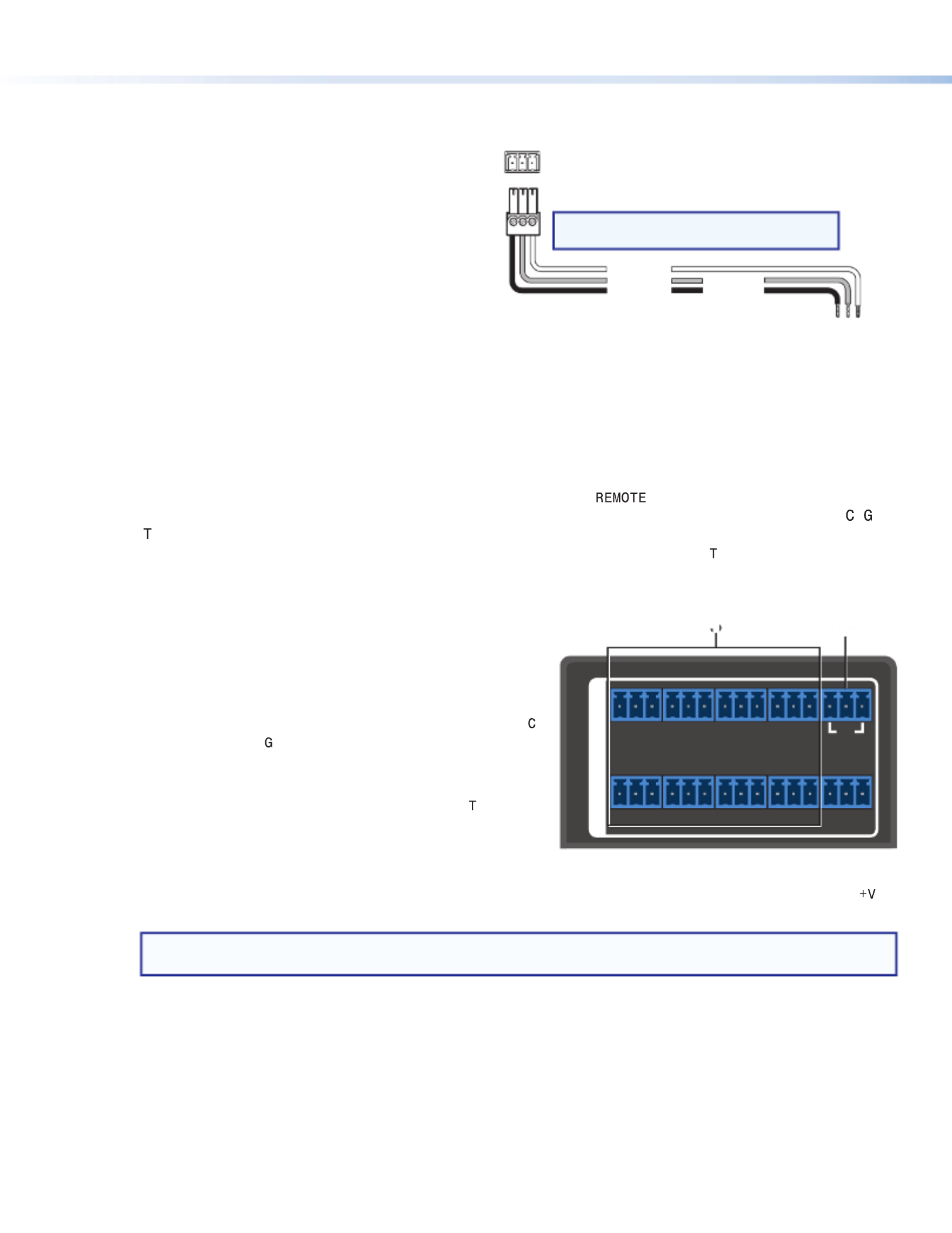
• RS-232 port — Connect the unterminated
transmit, receive, and ground wires of the RS-232
cable to the provided 3-pole captive screw plug, as
shown in the illustration at right. Connect the plug
between the rear panel RS-232 connector (
E), and
the serial port of your computer. Protocol for the
RS-232 port is 9600 baud, 8 data bits, 1 stop bit,
no parity.
• Config port — Connect a USB mini-B cable between the front panel USB mini-B connector (see figure 2,
B, on page 3) and a USB port on your computer for control via USB.
• LAN port — Use an RJ-45 cable to connect this jack (see figure 1,
F) to a LAN for Ethernet control of the
switcher.
6. (Optional) Connect contact closure and indicator devices. The panel on the SW6 and SW8
models contains six (SW6) or eight (SW8) 3-pole captive screw connectors, each with three pins labeled , ,
and , for contact closure and tally indicator devices. The panel also contains a 3-pole captive screw connector
with three +V pins that provide power to the indicator devices connected to the tally ( ) ports (see
2 in the
illustration below right).
Each 3-pole connector is labeled with the number of the HDMI input associated with it. Wire devices to these
connectors as follows:
a. Connect contact input and tally output devices to one or
more of the 3-pole CONTACT IN/TALLY OUT connectors
(see 1 in the illustration at right), as desired:
• To enable input switching via contact closure, connect
a push-button contact closure input device to pins
(contact) and (ground).
• To identify the currently selected input when the front
panel buttons are not visible, connect an indicator
device, such as an LED, to tally output pin of the
same 3-pole connector.
When the input you are using is selected, the
corresponding tally out pin shorts to ground, which activates the connected indicator.
b. If desired, attach the power wires for your connected indicator devices to any of the three ports of the
connector (2).
NOTE: You need to connect the indicator LED to the voltage output if you want to power the device for
visual feedback. However, only the contact and ground connections are needed to select an input.
Pressing the button on the contact closure device switches the connected input to the output.
Computer or
Control Syste
m
RS-232 Port
SW HD 4K Series Switcher
Rear Panel
Remote Port
NOTE: If you use cable that has a drain
wire, tie the drain wi to ground at both ends.re
Ground (G)
Transmit (Tx)
Receive (Rx) Transmit (Tx)
Receive (Rx)
Tx Rx G
RS-232
Tx Rx G
GC T GC
G
1
2
3
4
C T TGC G
6 8
C T TGC
T GC T GC
5 7
T +V
RS-232
CONTACT IN/TALLY OUT
REMOTE
1 2

3
Using a Show Me® cable:
The Contact and Tally connectors can also be used with Extron Show Me cables. The
diagram at right shows how to wire a Show Me cable to a contact input.
For each Show Me cable:
• Connect the pigtail to the pin corresponding to the input being used. red C
• Connect the pigtail to the pin of the same input.black T
NOTE: The ground or drain wire on the Show Me cable is not used here. You can tie
it back and shield it.
7. Connect the rear panel IEC power connector to an AC source (see figure 1,
A, on page 1).
8. Power on the output display.
9. Power on the source devices.
Front Panel Features
E
SW8 HD 4K PLUS
HDMI SWITCHER
1
CONFIG
SIGNAL
INPUTS
INPUTS OUTPUT
1 2 3 4 5 6 7 8
HDCP
2 3 4
AUTO
SWITCH
5 6 7 8
CA B
D
A
AUTO SWITCH LED D HDCP LEDs
B
USB CONFIG port E Input selection buttons
C SIGNAL LEDs
Figure 2. SW6 and SW8 HD 4K
PLUS
Front Panels
NOTE: The SW6 front panel is identical to that of the SW8 except that it has six input buttons, Signal LEDs, and
HDCP LEDs.
A AUTO SWITCH LED — Lights when auto-input switching is in effect. When auto-input switching is enabled, the
switcher automatically switches to the highest-numbered input with an active video signal.
B USB CONFIG port — Connect a USB cable (USB A to mini-B) between your computer and this female USB
mini-B port to configure and control the switcher via SIS commands or PCS, and to update the firmware.
C SIGNAL LEDs — The LEDs labeled INPUTS each light when the corresponding input is connected to a device
that has power. The LED labeled OUTPUT lights when the output is connected to a device that has power.
D HDCP LEDs
• Input LEDs — Light if the connected sources are HDCP encrypted and have been authenticated by the
switcher inputs.
NOTE: If the source device connected to the selected input is HDCP encrypted (requires HDCP
authentication), the corresponding signal LED may not light unless HDCP has been authenticated.
• Output LED — Lights when the currently selected input requires HDCP and the connected output device
has been successfully authenticated.
NOTE: HDCP is re-authenticated on the output whenever a new input is selected.
CONTACT IN/ LLY OUTTA
Connector
Black
Red
Show Me
Cable
C T G
1
G
2
C T
SW6 and SW8 HD 4K PLUS
Produktspezifikationen
| Marke: | Extron |
| Kategorie: | Schalten |
| Modell: | SW HD 4K PLUS Series |
Brauchst du Hilfe?
Wenn Sie Hilfe mit Extron SW HD 4K PLUS Series benötigen, stellen Sie unten eine Frage und andere Benutzer werden Ihnen antworten
Bedienungsanleitung Schalten Extron

6 September 2024
6 September 2024
5 September 2024
Bedienungsanleitung Schalten
- Schalten Asus
- Schalten Belkin
- Schalten Hama
- Schalten HP
- Schalten LogiLink
- Schalten Manhattan
- Schalten Nedis
- Schalten Philips
- Schalten SilverCrest
- Schalten Panasonic
- Schalten Brennenstuhl
- Schalten Clas Ohlson
- Schalten Cotech
- Schalten Profile
- Schalten ZyXEL
- Schalten Bosch
- Schalten Yamaha
- Schalten Powerfix
- Schalten CSL
- Schalten Eminent
- Schalten Linksys
- Schalten Netgear
- Schalten König
- Schalten PCE
- Schalten Renkforce
- Schalten Trotec
- Schalten Schneider
- Schalten Rex
- Schalten Kaiser
- Schalten Vivanco
- Schalten Abus
- Schalten Elro
- Schalten Smartwares
- Schalten Tesla
- Schalten Perel
- Schalten Nexa
- Schalten Tork
- Schalten GEV
- Schalten Goobay
- Schalten Lindy
- Schalten Tripp Lite
- Schalten Ansmann
- Schalten Mercusys
- Schalten Marmitek
- Schalten Honeywell
- Schalten TRENDnet
- Schalten TP-Link
- Schalten Kathrein
- Schalten Flamingo
- Schalten Alcatel
- Schalten Tiptel
- Schalten Black Box
- Schalten Alpine
- Schalten Techly
- Schalten Ebode
- Schalten Theben
- Schalten Vacmaster
- Schalten GAO
- Schalten Hager
- Schalten Behringer
- Schalten Omnitronic
- Schalten Monoprice
- Schalten Ecler
- Schalten Monacor
- Schalten Huawei
- Schalten JUNG
- Schalten Victron Energy
- Schalten Ei Electronics
- Schalten Edimax
- Schalten Totolink
- Schalten D-Link
- Schalten Sylvania
- Schalten Audiovox
- Schalten B-Tech
- Schalten QNAP
- Schalten SPC
- Schalten Speaka
- Schalten Digitus
- Schalten Sygonix
- Schalten DataVideo
- Schalten Lancom
- Schalten LevelOne
- Schalten Merten
- Schalten APC
- Schalten Eberle
- Schalten Cisco
- Schalten Delta Dore
- Schalten Grässlin
- Schalten Tenda
- Schalten CyberPower
- Schalten Boss
- Schalten IFM
- Schalten Intertechno
- Schalten Elation
- Schalten Ubiquiti Networks
- Schalten Kramer
- Schalten Aeon Labs
- Schalten Intellinet
- Schalten Eaton
- Schalten AV:link
- Schalten Hikvision
- Schalten Vemer
- Schalten PreSonus
- Schalten Planet
- Schalten EnGenius
- Schalten Finder
- Schalten Mikrotik
- Schalten Shimano
- Schalten Homematic IP
- Schalten Berker
- Schalten Dormakaba
- Schalten Emerson
- Schalten Generac
- Schalten Intermatic
- Schalten KlikaanKlikuit
- Schalten Mercury
- Schalten Paladin
- Schalten Provision ISR
- Schalten Robbe
- Schalten SEC24
- Schalten Steren
- Schalten Suevia
- Schalten AMX
- Schalten Triax
- Schalten WHALE
- Schalten Vimar
- Schalten Cudy
- Schalten Siig
- Schalten Electro Harmonix
- Schalten RGBlink
- Schalten Iogear
- Schalten StarTech.com
- Schalten Smart-AVI
- Schalten Dahua Technology
- Schalten PAC
- Schalten Gefen
- Schalten Avocent
- Schalten Legrand
- Schalten Atlantis Land
- Schalten CYP
- Schalten H-Tronic
- Schalten ATen
- Schalten Axing
- Schalten KanexPro
- Schalten SmartAVI
- Schalten Advantech
- Schalten Kraus & Naimer
- Schalten Chacon
- Schalten Juniper
- Schalten Fibaro
- Schalten Phoenix Contact
- Schalten Audac
- Schalten OSD Audio
- Schalten Wentronic
- Schalten SunBriteTV
- Schalten BZBGear
- Schalten Crestron
- Schalten Kemo
- Schalten ORNO
- Schalten Atlona
- Schalten Equip
- Schalten Heitronic
- Schalten Hamlet
- Schalten STI
- Schalten Matrox
- Schalten Blustream
- Schalten Vivolink
- Schalten Mach Power
- Schalten Ernitec
- Schalten Cambium Networks
- Schalten ConnectPro
- Schalten Micro Connect
- Schalten Intelix
- Schalten ICasa
- Schalten Maclean Energy
- Schalten Cooking Performance Group
- Schalten Flic
- Schalten Liberty
- Schalten Noark
- Schalten 2USB
- Schalten KVM-TEC
- Schalten Setti+
- Schalten PureLink
Neueste Bedienungsanleitung für -Kategorien-

15 Oktober 2024
12 Oktober 2024
11 Oktober 2024
8 Oktober 2024
8 Oktober 2024
5 Oktober 2024
4 Oktober 2024
4 Oktober 2024
4 Oktober 2024
3 Oktober 2024