Cisco UCS C460 M4 Bedienungsanleitung
Lesen Sie kostenlos die 📖 deutsche Bedienungsanleitung für Cisco UCS C460 M4 (142 Seiten) in der Kategorie Server. Dieser Bedienungsanleitung war für 31 Personen hilfreich und wurde von 2 Benutzern mit durchschnittlich 4.5 Sternen bewertet
Seite 1/142

Americas Headquarters
Cisco Systems, Inc.
170 West Tasman Drive
San Jose, CA 95134-1706
USA
http://www.cisco.com
Tel: 408 526-4000
800 553-NETS (6387)
Fax: 408 527-0883
Cisco UCS C460 M4 Server
Installation and Service Guide
April 20, 2016
Text Part Number: OL-31215-01

THE SPECIFICATIONS AND INFORMATION REGARDING THE PRODUCTS IN THIS MANUAL ARE SUBJECT TO CHANGE WITHOUT NOTICE. ALL
STATEMENTS, INFORMATION, AND RECOMMENDATIONS IN THIS MANUAL ARE BELIEVED TO BE ACCURATE BUT ARE PRESENTED WITHOUT
WARRANTY OF ANY KIND, EXPRESS OR IMPLIED. USERS MUST TAKE FULL RESPONSIBILITY FOR THEIR APPLICATION OF ANY PRODUCTS.
THE SOFTWARE LICENSE AND LIMITED WARRANTY FOR THE ACCOMPANYING PRODUCT ARE SET FORTH IN THE INFORMATION PACKET THAT
SHIPPED WITH THE PRODUCT AND ARE INCORPORATED HEREIN BY THIS REFERENCE. IF YOU ARE UNABLE TO LOCATE THE SOFTWARE LICENSE
OR LIMITED WARRANTY, CONTACT YOUR CISCO REPRESENTATIVE FOR A COPY.
The following information is for FCC compliance of Class A devices: This equipment has been tested and found to comply with the limits for a Class A digital device, pursuant
to part 15 of the FCC rules. These limits are designed to provide reasonable protection against harmful interference when the equipment is operated in a commercial
environment. This equipment generates, uses, and can radiate radio-frequency energy and, if not installed and used in accordance with the instruction manual, may cause
harmful interference to radio communications. Operation of this equipment in a residential area is likely to cause harmful interference, in which case users will be required
to correct the interference at their own expense.
The following information is for FCC compliance of Class B devices: This equipment has been tested and found to comply with the limits for a Class B digital device, pursuant
to part 15 of the FCC rules. These limits are designed to provide reasonable protection against harmful interference in a residential installation. This equipment generates,
uses and can radiate radio frequency energy and, if not installed and used in accordance with the instructions, may cause harmful interference to radio communications.
However, there is no guarantee that interference will not occur in a particular installation. If the equipment causes interference to radio or television reception, which can be
determined by turning the equipment off and on, users are encouraged to try to correct the interference by using one or more of the following measures:
• Reorient or relocate the receiving antenna.
• Increase the separation between the equipment and receiver.
• Connect the equipment into an outlet on a circuit different from that to which the receiver is connected.
• Consult the dealer or an experienced radio/TV technician for help.
Modifications to this product not authorized by Cisco could void the FCC approval and negate your authority to operate the product.
The Cisco implementation of TCP header compression is an adaptation of a program developed by the University of California, Berkeley (UCB) as part of UCB’s public
domain version of the UNIX operating system. All rights reserved. Copyright © 1981, Regents of the University of California.
NOTWITHSTANDING ANY OTHER WARRANTY HEREIN, ALL DOCUMENT FILES AND SOFTWARE OF THESE SUPPLIERS ARE PROVIDED “AS IS” WITH
ALL FAULTS. CISCO AND THE ABOVE-NAMED SUPPLIERS DISCLAIM ALL WARRANTIES, EXPRESSED OR IMPLIED, INCLUDING, WITHOUT
LIMITATION, THOSE OF MERCHANTABILITY, FITNESS FOR A PARTICULAR PURPOSE AND NONINFRINGEMENT OR ARISING FROM A COURSE OF
DEALING, USAGE, OR TRADE PRACTICE.
IN NO EVENT SHALL CISCO OR ITS SUPPLIERS BE LIABLE FOR ANY INDIRECT, SPECIAL, CONSEQUENTIAL, OR INCIDENTAL DAMAGES, INCLUDING,
WITHOUT LIMITATION, LOST PROFITS OR LOSS OR DAMAGE TO DATA ARISING OUT OF THE USE OR INABILITY TO USE THIS MANUAL, EVEN IF CISCO
OR ITS SUPPLIERS HAVE BEEN ADVISED OF THE POSSIBILITY OF SUCH DAMAGES.
Cisco and the Cisco logo are trademarks or registered trademarks of Cisco and/or its affiliates in the U.S. and other countries. To view a list of Cisco trademarks, go to this
URL: www.cisco.com/go/trademarks. Third-party trademarks mentioned are the property of their respective owners. The use of the word partner does not imply a partnership
relationship between Cisco and any other company. (1110R)
Any Internet Protocol (IP) addresses and phone numbers used in this document are not intended to be actual addresses and phone numbers. Any examples, command display
output, network topology diagrams, and other figures included in the document are shown for illustrative purposes only. Any use of actual IP addresses or phone numbers in
illustrative content is unintentional and coincidental.
Cisco UCS C460 M4 Server Installation and Service Guide
© 2016 Cisco Systems, Inc. All rights reserved.

iii
Cisco UCS C460 M4 Server Installation and Service Guide
OL-31215-01
C O N T E N T S
Preface vii
Audience vii
Conventions vii
Related Documentation xiv
Documentation Feedback xiv
Obtaining Documentation and Submitting a Service Request xiv
C H A P T E R
1Overview 1-1
Front Panel Features 1-1
Rear Panel Features 1-2
Replaceable Component Locations 1-3
Server Features Overview 1-4
C H A P T E R
2Installing the Server 2-1
Unpacking and Inspecting the Server 2-2
Preparing for Server Installation 2-3
Installation Guidelines 2-3
Rack Requirements 2-4
Equipment Requirements 2-4
Slide Rail Adjustment Range 2-4
Installing the Server in a Rack 2-5
Installing the Slide Rails 2-5
Installing the Cable Management Arm (Optional) 2-9
Reversing the Cable Management Arm (Optional) 2-10
Initial Server Setup 2-11
Connecting and Powering on the Server (Standalone Mode) 2-11
NIC Modes and NIC Redundancy Settings 2-14
NIC Modes 2-14
NIC Redundancy 2-14
System BIOS and Cisco IMC Firmware 2-15
Updating the BIOS and Cisco IMC Firmware 2-15
Accessing the System BIOS 2-16

Contents
iv
Cisco UCS C460 M4 Server Installation and Service Guide
OL-31215-01
C H A P T E R
3Maintaining the Server 3-1
Standalone Server Monitoring and Management Tools 3-1
Cisco Integrated Management Interface 3-1
Server Configuration Utility 3-1
Status LEDs and Buttons 3-2
Front-Panel LEDs 3-2
Rear-Panel LEDs and Buttons 3-5
Internal Diagnostic LEDs 3-7
Preparing for Server Component Installation 3-8
Required Equipment 3-8
Shutting Down and Powering Off the Server 3-8
Removing or Replacing the Front Bezel (Optional) 3-9
Removing or Replacing the Server Top Cover 3-10
Replaceable Component Locations 3-11
Hot-Swap or Hot-Plug Replacement 3-12
Replacing Server Components 3-13
Replacing SAS/SATA Hard Drives or Solid State Drives 3-14
SAS/SATA Drive Population Guidelines 3-14
Replacing a SAS or SATA Drive 3-15
Replacing an NVMe PCIe SSD 3-17
NVMe PCIe SSD Population Guidelines 3-17
NVMe PCIe SSD Requirements and Restrictions 3-17
Replacing an NVMe PCIe SSD 3-17
Replacing Fan Modules 3-19
Replacing Memory Risers 3-20
Memory Riser Population Guidelines 3-20
Identifying a Faulty Memory Riser or DIMM 3-21
Replacing a Memory Riser 3-21
Replacing DIMMs 3-23
DIMM Performance Guidelines and Population Rules 3-23
Replacing a DIMM 3-28
Replacing CPUs and Heat Sinks 3-29
Special Information For Upgrades to Intel Xeon v3 Series CPUs 3-29
CPU Configuration Rules 3-30
Replacing a CPU and Heat Sink 3-30
Additional CPU-Related Parts to Order with RMA Replacement Motherboards 3-36
Replacing a RAID Controller Card 3-37
RAID Card Firmware Compatibility 3-37
Replacement Procedure 3-37

Contents
v
Cisco UCS C460 M4 Server Installation and Service Guide
OL-31215-01
Replacing a Modular RAID Controller Transportable Memory Module (TMM) 3-38
Replacing the Supercap Power Module (RAID Backup Unit) 3-41
Replacing a PCIe Riser 3-43
Replacing a PCIe Card 3-45
PCIe Slots 3-45
PCIe Configuration Guide For Optimum Performance 3-46
Special Considerations for Cisco UCS Virtual Interface Cards 3-48
Special Considerations for Cisco UCS Fusion ioDrive2 Storage Accelerator Cards 3-49
Replacing a PCIe Card 3-50
Installing Multiple PCIe Cards and Resolving Limited Resources 3-52
Replacing an NVIDIA GPU Card 3-55
Replacing the Motherboard RTC Battery 3-55
Replacing a Media Riser Card 3-57
Replacing a Cisco Flexible Flash Drive 3-59
Monitoring and Managing a Cisco Flexible Flash Drive 3-59
Synchronizing RAID After Installing a Second Cisco Flexible Flash Drive 3-59
Replacing a Cisco Flexible Flash Drive 3-59
Replacing an Internal USB Drive 3-61
Internal USB Drive Replacement Procedure 3-61
Enabling or Disabling the Internal USB Port 3-61
Installing and Enabling a Trusted Platform Module 3-62
Installing the TPM Hardware 3-62
Enabling TPM Support in the BIOS 3-63
Enabling the Intel TXT Feature in the BIOS 3-64
Replacing Power Supplies 3-65
Service DIP Switches 3-66
DIP Switch Location on the Media Riser Card 3-66
Using the Clear Password DIP Switch 3-67
Using the BIOS Recovery DIP Switch 3-68
Using the Clear CMOS DIP Switch 3-69
A P P E N D I X
AServer Specifications A-1
Physical Specifications A-1
Environmental Specifications A-2
Power Specifications A-2
A P P E N D I X
BPower Cord Specifications B-1
Supported Power Cords and Plugs B-1
AC Power Cord Illustrations B-3

Contents
vi
Cisco UCS C460 M4 Server Installation and Service Guide
OL-31215-01
A P P E N D I X
CRAID Controller Considerations C-1
Supported RAID Controllers and Required Cables C-2
Write-Cache Policy for Cisco 12G SAS Modular RAID Controller C-3
RAID Card Firmware Compatibility C-3
Supercap Power Module (RAID Backup Unit) C-3
RAID Controller Cabling C-4
SAS Cable-to-Drive Bay Mapping C-4
Cabling an 8-Port RAID Controller C-5
Cabling a 12-Port RAID Controller C-6
Restoring RAID Configuration After Replacing a RAID Controller C-7
For More Information C-7
A P P E N D I X
DGPU Card Installation D-1
Overview of Server Firmware Requirements D-1
NVIDIA GPU Slot Population Rules D-2
Requirement For All Supported GPUs: Memory-Mapped I/O Greater than 4 GB D-2
Installing a GPU Card D-3
NVIDIA Tesla M60 GPU GRID Software and Licensing D-5
Installation Overview D-5
NVIDIA GRID License Server Overview D-6
Registering Your Product Activation Keys With NVIDIA D-7
Downloading the GRID Software Suite D-7
Installing NVIDIA GRID License Server Software D-8
Installing GRID Licenses From the NVIDIA Licensing Portal to the License Server D-10
Managing GRID Licenses D-11
Switching Between Compute Mode and Graphics Mode D-13
Installing Drivers to Support the NVIDIA GPU Cards D-15
A P P E N D I X
EInstallation for Cisco UCS Integration E-1

x
Cisco UCS C460 M4 Server Installation and Service Guide
OL-31215-01

xi
Cisco UCS C460 M4 Server Installation and Service Guide
OL-31215-01
Aviso
INSTRUÇÕES IMPORTANTES DE SEGURANÇA
Este símbolo de aviso significa perigo. Você se encontra em uma situação em que há risco de lesões
corporais. Antes de trabalhar com qualquer equipamento, esteja ciente dos riscos que envolvem os
circuitos elétricos e familiarize-se com as práticas padrão de prevenção de acidentes. Use o
número da declaração fornecido ao final de cada aviso para localizar sua tradução nos avisos de
segurança traduzidos que acompanham o dispositivo.
GUARDE ESTAS INSTRUÇÕES
Advarsel
VIGTIGE SIKKERHEDSANVISNINGER
Dette advarselssymbol betyder fare. Du befinder dig i en situation med risiko for
legemesbeskadigelse. Før du begynder arbejde på udstyr, skal du være opmærksom på de
involverede risici, der er ved elektriske kredsløb, og du skal sætte dig ind i standardprocedurer til
undgåelse af ulykker. Brug erklæringsnummeret efter hver advarsel for at finde oversættelsen i de
oversatte advarsler, der fulgte med denne enhed.
GEM DISSE ANVISNINGER
xii
Cisco UCS C460 M4 Server Installation and Service Guide
OL-31215-01

xiii
Cisco UCS C460 M4 Server Installation and Service Guide
OL-31215-01

xiv
Cisco UCS C460 M4 Server Installation and Service Guide
OL-31215-01
Obtaining Documentation and Submitting a Service Request
Related Documentation
The documentation set for the Cisco Unified Computing System (UCS) C-Series rack-mount servers is
described in the roadmap document at the following link:
Cisco UCS C-Series Documentation Roadmap
Documentation Feedback
To provide technical feedback on this document, or to report an error or omission, please send your
comments to ucs-docfeedback@external.cisco.com. We appreciate your feedback.
Obtaining Documentation and Submitting a Service Request
For information on obtaining documentation, using the Cisco Bug Search Tool (BST), submitting a
service request, and gathering additional information, see What’s New in Cisco Product Documentation.
To receive new and revised Cisco technical content directly to your desktop, you can subscribe to
the What’s New in Cisco Product Documentation RSS feed. The RSS feeds are a free service.

C H A P T E R
1-1
Cisco UCS C460 M4 Server Installation and Service Guide
OL-31215-01
1
Overview
This chapter provides an overview of the Cisco UCS C460 M4 server.
Front Panel Features
Figure 1-1 shows the front panel features of the server.
Figure 1-1 Front Panel Features
1Cooling fans (hot-swappable and
accessible from the front panel)
8Power supply status LED
2 9Operations panel Network link activity LED
3Power button/LED 10 Drive bays 5 and 9 support NVMe PCIe solid state drives
(SSDs) and SAS/SATA drives.
4Identification button/LED 11 Drive bays 1–12 support SAS/SATA drives.
5System status LED 12 KVM console connector (used with a KVM cable that
provides two USB, one VGA, and one serial connector)
6Fan status LED 13 Pull-out asset tag
7Temperature status LED –
FAN 1 FAN 2 FAN 3 FAN 4
HDD 01
HDD 05
HDD 09
HDD 02
HDD 06
HDD 10
HDD 03
HDD 07
HDD 11
HDD 04
HDD 08
HDD 12
352286
1
2
3
4
5
6
7
8
9
13
12
11
10
1-2
Cisco UCS C460 M4 Server Installation and Service Guide
OL-31215-01
Chapter 1 Overview
Rear Panel Features
Rear Panel Features
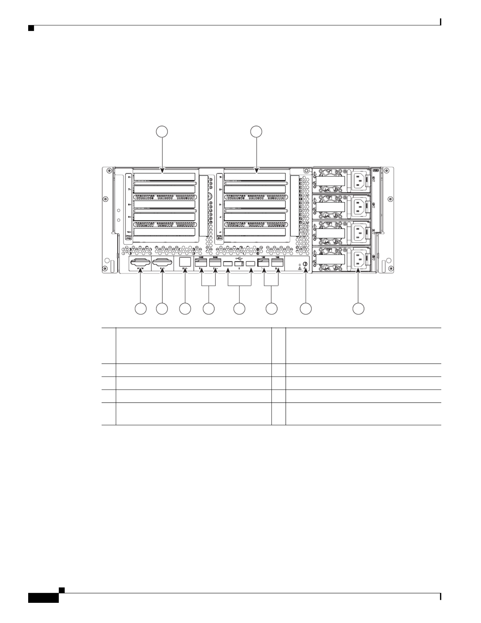
Figure 1-2 shows the rear panel features of the server.
Figure 1-2 Rear Panel Features
1PCIe riser 1 (slots 1–5)
See PCIe Slots, page 3-45 for slot
specifications.
610 Gb Ethernet ports (two)
2 7PCIe riser 2 (slots 6–10) USB 2.0 ports (three)
3 8Serial port (DB-9 connector) 1 Gb Ethernet ports (two)
4 9VGA video port (DB-15 connector) Rear identification LED/button
51 Gb Ethernet dedicated management port M1 10 Power supplies 1–4 (hot-swappable,
redundant as 2+2)
352287
PSU 1
PCIe 6
Riser 2
Riser 1
PCIe 7
PCIe 8
PCIe 9
PCIe 10
PSU 2
PSU 3
PSU 4
PCIe 1
PCIe 2
PCIe 3
PCIe 4
PCIe 5
2 1
3 4 5 6 7 8 9 10

1-3
Cisco UCS C460 M4 Server Installation and Service Guide
OL-31215-01
Chapter 1 Overview
Replaceable Component Locations
Replaceable Component Locations
This section shows the locations of the components that are discussed in this chapter. The view in
Figure 1-3 is from the top down with the top cover removed.
Figure 1-3 Replaceable Component Locations
1Drive bays (up to 12 2.5-inch drives)
•All 12 bays support SAS/SATA drives.
•Bays 5 and 9 support NVMe PCIe SSD
drives and SAS/SATA drives.
9Media riser card (includes two bays for Cisco
Flexible Flash drives, an internal USB port,
and the DIP switches)
2Fan modules (four, hot-swappable and
front-accessible)
10 Cisco Flexible Flash drive (SD card) bays
(two on the media riser card)
3RAID backup unit (supercap power module)
mounting bracket on chassis wall
11 Internal, vertical USB 2.0 port (on the media
riser card)
4RAID controller card socket (dedicated
internal PCIe socket)
12 PCIe riser 1 (PCIe slots 1–5)
5Memory risers with DIMMs (up to 8 risers with
12 DIMM sockets each)
13 PCIe riser 2, optional (PCIe slots 6–10)
6Chassis mid-brace 14 TPM socket and screw hole (on motherboard,
not visible under riser in this view)
7CPUs and heat sinks (two or four)
The CPUs and their heat sinks are below the
memory risers and PCIe risers.
15 RTC battery (on motherboard, not visible
under riser in this view)
8Power supplies (two or four, redundant as 2+2)
Power supplies are hot-swappable.
352297
CPU1
MEM 1
MEM 2
MEM 3
MEM 4
MEM 5
MEM 6
MEM 7
MEM 8
CPU2
CPU3
CPU4
PCIe Riser 1
PCIe Riser 2
2
3 4 65 7
8
9
10
11
12
13
1415
1
1-4
Cisco UCS C460 M4 Server Installation and Service Guide
OL-31215-01
Chapter 1 Overview
Server Features Overview
Server Features Overview
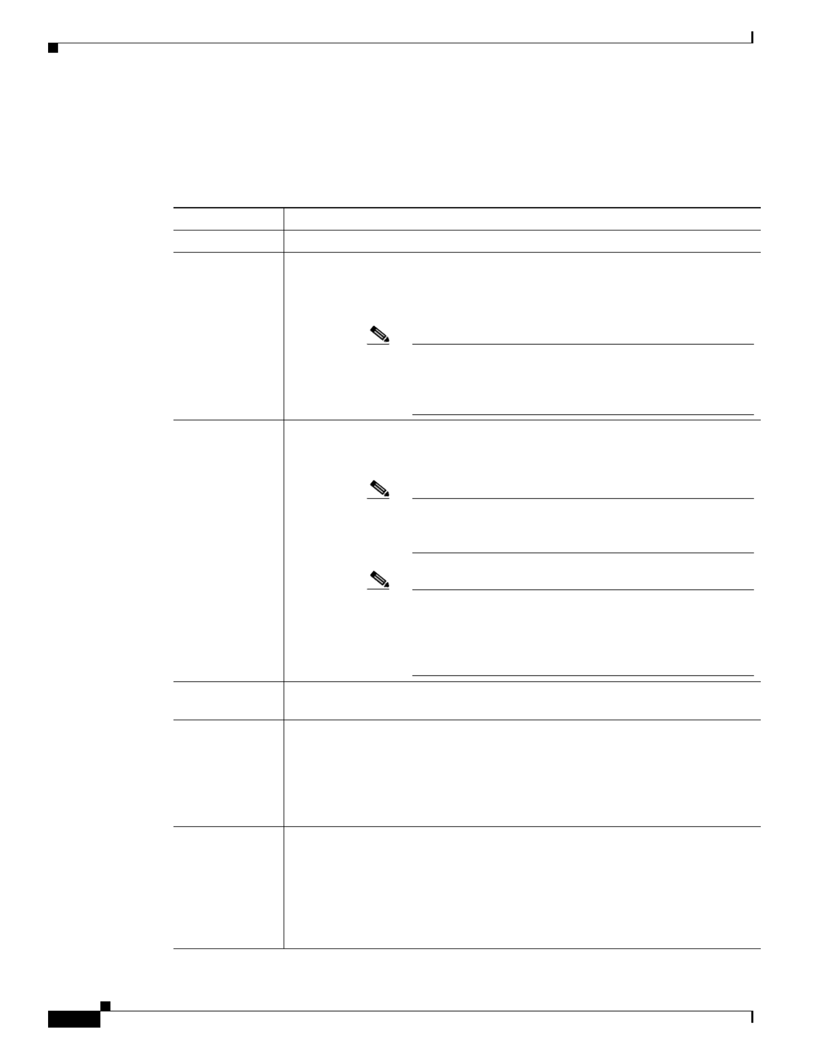
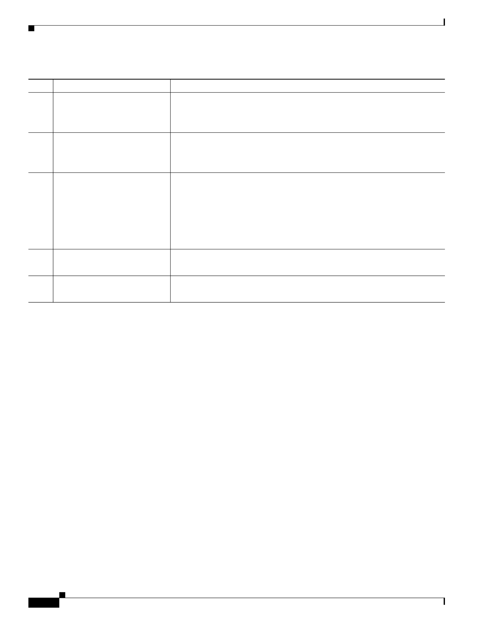
Table 1-1 lists the features of the server.
.
Table 1-1 Cisco UCS C460 M4 Server Features
Feature Description
Chassis Four rack-unit (4RU) chassis.
Processors Different versions of CPUs are available:
•Two or four Intel Xeon E7-4800 v2 or E7-8800 EX v2 Series processors.
•Two or four Intel Xeon E7-4800 v2 or E7-8800 EX v3 Series processors.
Note The Intel Xeon EX v3 Series CPUs require Cisco IMC 2.0(6)
or later firmware. They also require DDR4 memory risers and
DDR4 DIMMs. See Special Information For Upgrades to
Intel Xeon v3 Series CPUs, page 3-29.
Memory The server has up to 8 hot-pluggable memory risers that each have 12 DIMM slots,
for a total of 96 DIMM slots. Each CPU can control 2 memory risers (up to 24
DIMMs). Memory risers are hot-pluggable.
1 2
Note See the release notes for your operating system and your
Cisco IMC/BIOS release for details and restrictions on
hot-plugging: Cisco IMC Release Notes.
Note DDR4 memory risers and DDR4 DIMMs are orderable. They
require that the server is using Intel Xeon EX v3 Series CPUs
and is also running Cisco IMC 2.0(6) or later firmware. See
Special Information For Upgrades to Intel Xeon v3 Series
CPUs, page 3-29.
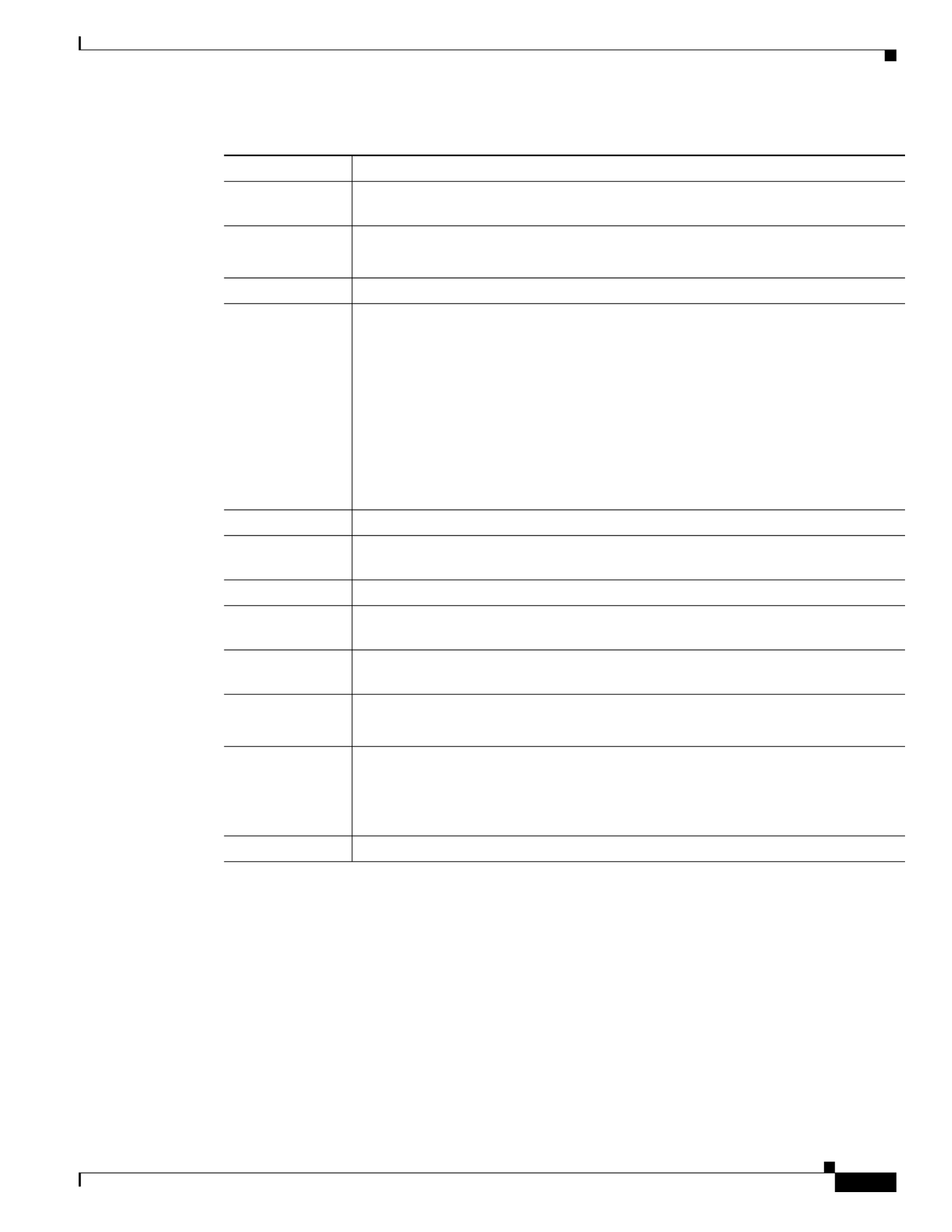
Multi-bit error
protection
This server supports multi-bit error protection.
Storage The server can hold up to 12 drives:
•All 12 drive bays support SAS and SATA drives.
•Drive bays 5 and 9 also support NVMe PCIe SSD drives that are compliant with
the Non-Volatile Memory Express (NVMe) protocol.
SAS and SATA drives are hot-swappable
3; PCIe drives are hot-pluggable.4
Disk
Management
For a list of supported RAID controller options, see RAID Controller
Considerations, page C-1.
There is one dedicated motherboard slot for a RAID controller card.
Note: At this time, the RAID controller can control only 8 of the 12 drive bays. See
Replacing SAS/SATA Hard Drives or Solid State Drives, page 3-14.
Note: The RAID controller cannot control PCIe drives.
1-5
Cisco UCS C460 M4 Server Installation and Service Guide
OL-31215-01
Chapter 1 Overview
Server Features Overview
RAID Backup The optional supercap power module (SCPM) mounts to a bracket on the chassis
wall.
PCIe I/O One or two PCIe risers with five horizontal PCIe slots each.
See PCIe Slots, page 3-45 for slot specifications.
InfiniBand The bus slots in this server support the InfiniBand architecture.
Network and
management I/O
The server provides these rear panel connectors:
•One 10/100/1000 dedicated management Ethernet port
•Two 1-Gb BASE-T Ethernet ports
•Two 10-Gb BASE-T Ethernet ports
•One RS-232 serial port (DB-9 connector)
•One VGA video port (DB-15 connector)
•Three USB 2.0 connectors
The server also has one front-panel KVM connector that is used with the included
KVM cable, which provides two USB, one VGA, and one serial connector.
WoL The 1-Gb BASE-T Ethernet LAN ports support the wake-on-LAN (WoL) standard.
Cisco Flexible
Flash drive
Up to two Cisco Flexible Flash drives in the SD card slots that are on the media riser.
Internal USB The server includes one internal USB 2.0 slot on the internal media riser.
Power Four power supplies, 1400 W each.
Hot-swappable and redundant as 2+2.
ACPI This server supports the advanced configuration and power interface (ACPI) 4.0
standard.
Cooling Four fan modules, hot-swappable and front-accessible.
In addition, there is 1 fan in each power supply.
Baseboard
management
Cisco Integrated Management Controller (Cisco IMC) firmware.
Depending on your settings, the Cisco IMC can be accessed through the
10/100/1000 dedicated management ports, the 1-Gb LOM ports, or a Cisco virtual
interface card.
Video Resolution up to 1600 x1200, 16 bpp at 60 Hz. Up to 256 MB of video memory.
1. Hot-pluggable = Software shutdown of the component is required before removing while the server is powered on.
2. Memory hot-plug requires an operating system that supports this feature.
3. Hot-swappable = No preconditioning of the component is required before removal while the server is powered on.
4. Hot-pluggable = The component must be shut down in the operating system before removal while the server is powered on.
Table 1-1 Cisco UCS C460 M4 Server Features (continued)
Feature Description

1-6
Cisco UCS C460 M4 Server Installation and Service Guide
OL-31215-01
Chapter 1 Overview
Server Features Overview

C H A P T E R
2-1
Cisco UCS C460 M4 Server Installation and Service Guide
OL-31215-01
2
Installing the Server
This chapter describes how to install the server, and it includes the following sections:
•Unpacking and Inspecting the Server, page 2-2
•Preparing for Server Installation, page 2-3
•Installing the Server in a Rack, page 2-5
•Initial Server Setup, page 2-11
•NIC Modes and NIC Redundancy Settings, page 2-14
•System BIOS and Cisco IMC Firmware, page 2-15
Note Before you install, operate, or service a server, review the Regulatory Compliance and Safety
Information for Cisco UCS C-Series Servers for important safety information.
Warning
IMPORTANT SAFETY INSTRUCTIONS
This warning symbol means danger. You are in a situation that could cause bodily injury. Before you
work on any equipment, be aware of the hazards involved with electrical circuitry and be familiar
with standard practices for preventing accidents. Use the statement number provided at the end of
each warning to locate its translation in the translated safety warnings that accompanied this device.
Statement 1071
SAVE THESE INSTRUCTIONS
2-2
Cisco UCS C460 M4 Server Installation and Service Guide
OL-31215-01
Chapter 2 Installing the Server
Unpacking and Inspecting the Server
Unpacking and Inspecting the Server
Caution When handling internal server components, wear an ESD strap and handle modules by the carrier edges
only.
Note The chassis is thoroughly inspected before shipment. If any damage occurred during transportation or
any items are missing, contact your customer service representative immediately.
To inspect the shipment, follow these steps:
Step 1 Remove the server from its cardboard container and save all packaging material.
Step 2 Compare the shipment to the equipment list provided by your customer service representative and
Figure 2-1. Verify that you have all items.
Step 3 Check for damage and report any discrepancies or damage to your customer service representative. Have
the following information ready:
•Invoice number of shipper (see the packing slip)
•Model and serial number of the damaged unit
•Description of damage
•Effect of damage on the installation
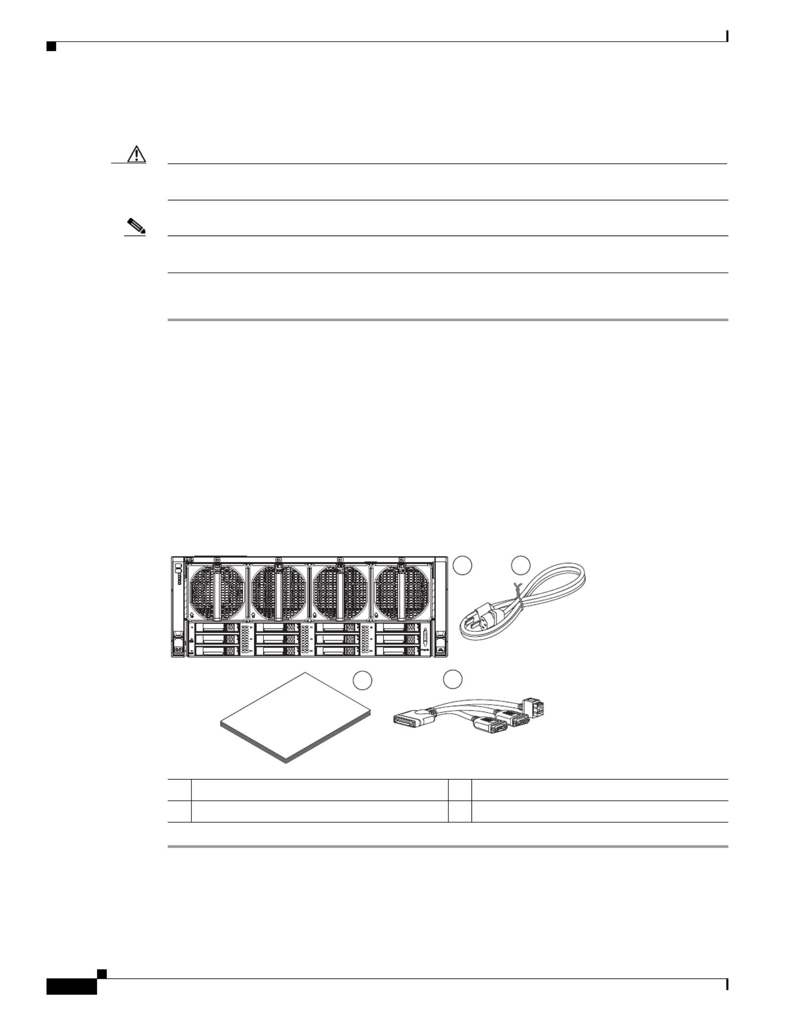
Figure 2-1 Shipping Box Contents
1 3Server Documentation
2 Power cord (up to four) 4 KVM cable
Ci cos
UC C- erieS S s
21
34
3 88522

2-3
Cisco UCS C460 M4 Server Installation and Service Guide
OL-31215-01
Chapter 2 Installing the Server
Preparing for Server Installation
Preparing for Server Installation
This section provides information about preparing for server installation, and it includes the following
topics:
•Installation Guidelines, page 2-3
•Rack Requirements, page 2-4
•Equipment Requirements, page 2-4
•Slide Rail Adjustment Range, page 2-4
Installation Guidelines
Warning
To prevent the system from overheating, do not operate it in an area that exceeds the maximum
recommended ambient temperature of: 35° C (95° F).
Statement 1047
Warning
The plug-socket combination must be accessible at all times, because it serves as the main
disconnecting device.
Statement 1019
Warning
This product relies on the building’s installation for short-circuit (overcurrent) protection. Ensure that
the protective device is rated not greater than: 250 V, 15 A.
Statement 1005
Warning
Installation of the equipment must comply with local and national electrical codes.
Statement 1074
When you are installing a server, use the following guidelines:
•Plan your site configuration and prepare the site before installing the server. See the Cisco UCS Site
Preparation Guide for the recommended site planning tasks.
•Ensure that there is adequate space around the server to allow for servicing the server and for
adequate airflow. The airflow in this server is from front to back.
•Ensure that the air-conditioning meets the thermal requirements listed in the Server Specifications.
•Ensure that the cabinet or rack meets the requirements listed in the “Rack Requirements” section on
page 2-4.
•Ensure that the site power meets the power requirements listed in the Server Specifications. If
available, you can use an uninterruptible power supply (UPS) to protect against power failures.
Caution Avoid UPS types that use ferroresonant technology. These UPS types can become unstable with systems
such as the Cisco UCS, which can have substantial current draw fluctuations from fluctuating data traffic
patterns.

2-4
Cisco UCS C460 M4 Server Installation and Service Guide
OL-31215-01
Chapter 2 Installing the Server
Preparing for Server Installation
Rack Requirements
This section provides the requirements for the standard open racks, assuming an external ambient air
temperature range of 41° F to 95° F (5° C to 35° C).
The rack must be of the following type:
•A standard 19-in. (48.3-cm) wide, four-post EIA rack, with mounting posts that conform to English
universal hole spacing, per section 1 of ANSI/EIA-310-D-1992.
•The rack post holes can be square 0.38-inch (9.6 mm), round 0.28-inch (7.1 mm), #12-24 UNC, or
#10-32 UNC when you use the supplied slide rails.
•The minimum vertical rack space per server must be four RUs, equal to 7 in. (17.78 cm).
Equipment Requirements
The slide rails supplied by Cisco Systems for this server do not require tools for installation if you install
them in a rack that has square 0.38-inch (9.6 mm), round 0.28-inch (7.1 mm), or #12-24 UNC threaded
holes.
Slide Rail Adjustment Range
The slide rails for this server have an adjustment range of 26 to 36 inches (660 to 914 mm).

2-5
Cisco UCS C460 M4 Server Installation and Service Guide
OL-31215-01
Chapter 2 Installing the Server
Installing the Server in a Rack
Installing the Server in a Rack
This section contains the following topics:
•Installing the Slide Rails, page 2-5
•Installing the Cable Management Arm (Optional), page 2-9
•Reversing the Cable Management Arm (Optional), page 2-10
Warning
To prevent bodily injury when mounting or servicing this unit in a rack, you must take special
precautions to ensure that the system remains stable. The following guidelines are provided to ensure
your safety:
This unit should be mounted at the bottom of the rack if it is the only unit in the rack.
When mounting this unit in a partially filled rack, load the rack from the bottom to the top with the heaviest component
at the bottom of the rack.
If the rack is provided with stabilizing devices, install the stabilizers before mounting or servicing the unit in the rack.
Statement 1006
Installing the Slide Rails
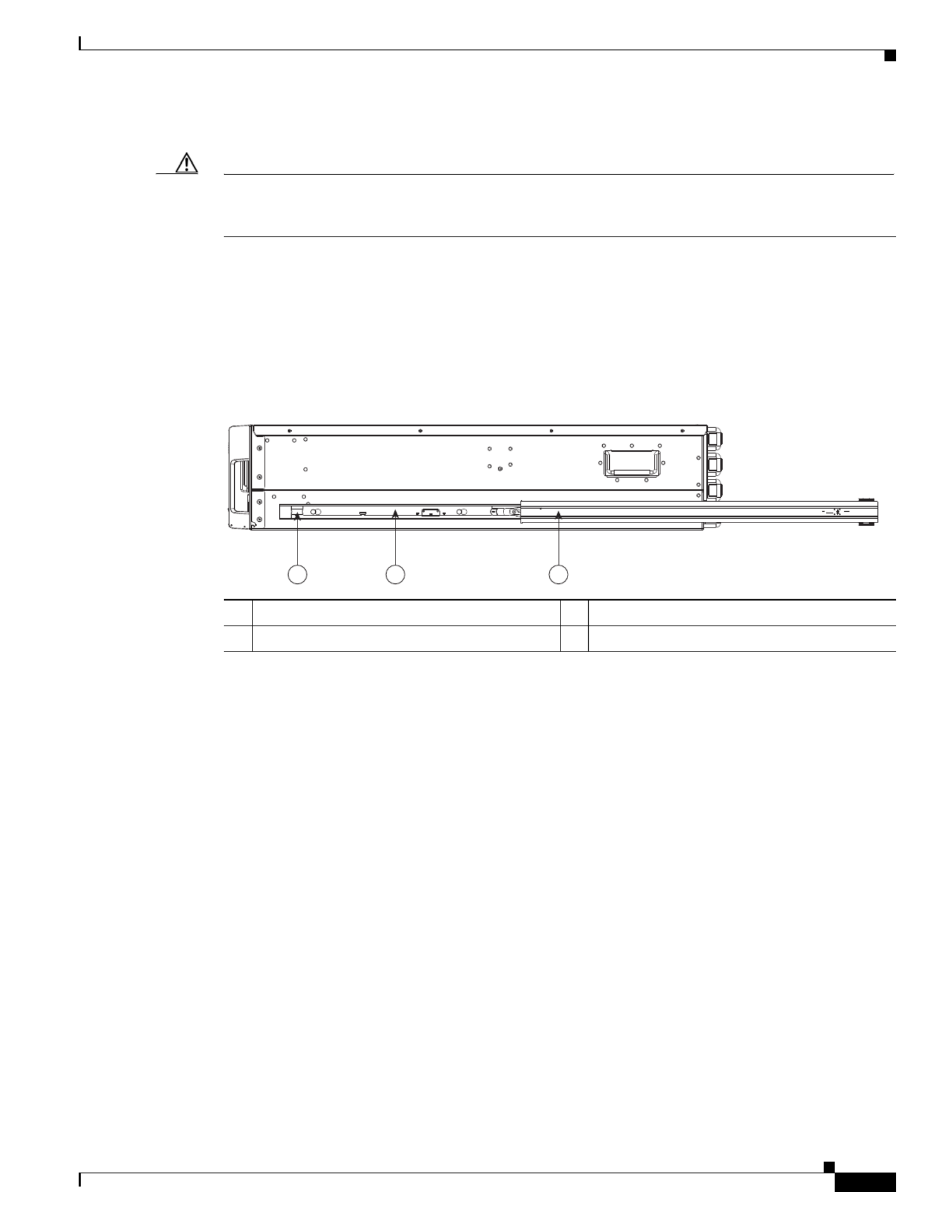
Step 1 Attach the inner rails to the sides of the server:
a. Align an inner rail with one side of the server so that the four keyed slots in the rail align with the
four pegs on the side of the server (see Figure 2-2).
b. Set the keyed slots over the pegs, and then slide the rail toward the rear to lock it in place on the pegs.
c. Install the second inner rail to the opposite side of the server.
Figure 2-2 Attaching Inner Rail to Side of Server
1 2Inner rail Pegs on side of server
2
1
352582

2-6
Cisco UCS C460 M4 Server Installation and Service Guide
OL-31215-01
Chapter 2 Installing the Server
Installing the Server in a Rack
Step 2 Open the front securing plate on both slide-rail assemblies. The front end of the slide-rail assembly has
a spring-loaded securing plate that must be open before you can insert the mounting pegs into the
rack-post holes.
On the outside of the assembly, push the green arrow button toward the rear to open the securing plate
(see Figure 2-3).
Figure 2-3 Front Securing Mechanism, Inside of Front End
Step 3 Install the slide rails into the rack:
a. Align one slide-rail assembly front end with the front rack-post holes that you want to use.
The slide rail front-end wraps around the outside of the rack post and the mounting pegs enter the
rack-post holes from the outside-front (see Figure 2-3).
Note The rack post must be between the mounting pegs and the open securing plate.
b. Push the mounting pegs into the rack-post holes.
c. Press the securing plate release button, marked PUSH. The spring-loaded securing plate closes to
lock the pegs in place.
d. Adjust the slide-rail length, and then push the rear mounting pegs into the corresponding rear
rack-post holes. The slide rail must be level front-to-rear.
The rear mounting pegs enter the rear rack-post holes from the inside of the rack post.
e. Attach the second slide-rail assembly to the opposite side of the rack. Ensure that the two slide-rail
assemblies are at the same height with each other and are level front-to-back.
f. Pull the inner slide rails on each assembly out toward the rack front until they hit the internal stops
and lock in place.
1 Front mounting pegs 3 Securing plate shown pulled back to open
position
2 Rack post
1
2
3
2-7
Cisco UCS C460 M4 Server Installation and Service Guide
OL-31215-01
Chapter 2 Installing the Server
Installing the Server in a Rack
Step 4 Insert the server into the slide rails:
Caution This server weighs approximately 130 pounds (59 kilograms) when fully loaded with components. We
recommend that you use a minimum of two people or a mechanical lift when lifting the server.
Attempting this procedure alone could result in personal injury or equipment damage.
a. Align the rear of the inner rails th s with the front ends of the empty at are attached to the server side
slide rails on the rack.
b. Push the server into the slide rails until it stops at the internal stops.
c. Slide the release clip toward the rear on both inner rails, and then continue pushing the server into
the rack until its front slam latches engage with the rack posts.
Figure 2-4 Inner Rail Release Clip
Step 5 (Optional) Secure the server in the rack more permanently by using the two screws that are provided with
the slide rails. Perform this step if you plan to move the rack with servers installed (see Figure 2-5).
With the server fully pushed into the slide rails, open a hinged slam latch lever on the front of the server
and insert the screw through the hole that is under the lever. The screw threads into the static part of the
rail on the rack post and prevents the server from being pulled out. Repeat for the opposite slam latch.
1 3Inner rail release clip Outer rail attached to rack post
2 Inner rail attached to server
1 2 3
352583

2-8
Cisco UCS C460 M4 Server Installation and Service Guide
OL-31215-01
Chapter 2 Installing the Server
Installing the Server in a Rack
Figure 2-5 Optional Securing Screws
1 4Rack post Screw hole on front end of slide rail
2 5Slam latch on server (closed) Screw hole on slam latch when open
3 6Front end of slide rail on rack post Slam latch on server (open)

2-9
Cisco UCS C460 M4 Server Installation and Service Guide
OL-31215-01
Chapter 2 Installing the Server
Installing the Server in a Rack
Installing the Cable Management Arm (Optional)
Note The CMA is reversible left to right. To reverse the CMA, see Reversing the Cable Management
Arm (Optional), page 2-10 before installation.
Step 1 With the server pushed fully into the rack, slide the CMA tab of the CMA arm that is farthest from the
server onto the end of the stationary slide rail that is attached to the rack post (see Figure 2-6). Slide the
tab over the end of the rail until it clicks and locks.
Step 2 Slide the CMA tab that is closest to the server over the end of the inner rail that is attached to the server
(see Figure 2-6). Slide the tab over the end of the rail until it clicks and locks.
Step 3 Pull out the width-adjustment slider that is at the opposite end of the CMA assembly until it matches the
width of your rack (see Figure 2-6).
Step 4 Slide the CMA tab that is at the end of the width-adjustment slider onto the end of the stationary slide
rail that is attached to the rack post (see Figure 2-6). Slide the tab over the end of the rail until it clicks
and locks.
Step 5 Open the hinged flap at the top of each plastic cable guide and route your cables through the cable guides
as desired.
Figure 2-6 Attaching the Cable Management Arm to the Rear of the Slide Rails
1 CMA tab on arm farthest from server and end
of stationary outer slide rail
3 CMA tab on width-adjustment slider and end
of stationary outer slide rail
2 CMA tab on arm closest to the server and end
of inner slide rail attached to server
4 Rear of server
352584
1
4
2
3

2-10
Cisco UCS C460 M4 Server Installation and Service Guide
OL-31215-01
Chapter 2 Installing the Server
Installing the Server in a Rack
Reversing the Cable Management Arm (Optional)
Step 1 Rotate the entire CMA assembly 180 degrees. The plastic cable guides must remain pointing upward.
Step 2 Flip the tabs at the end of each CMA arm so that they point toward the rear of the server.
Step 3 Pivot the tab that is at the end of the width-adjustment slider. Depress and hold the metal button on the
outside of the tab and pivot the tab 180 degrees so that it points toward the rear of the server.
Figure 2-7 Reversing the CMA
1 CMA tab on end of width-adjustment slider 2 Metal button for rotating
352585
12
PUSH

2-11
Cisco UCS C460 M4 Server Installation and Service Guide
OL-31215-01
Chapter 2 Installing the Server
Initial Server Setup
Initial Server Setup
This section includes the following topics:
•Connecting and Powering on the Server (Standalone Mode), page 2-11
•NIC Modes and NIC Redundancy Settings, page 2-14
Connecting and Powering on the Server (Standalone Mode)
This section describes how to power on the server, assign an IP address, and connect to server
management when using the server in standalone mode. To use the server in a Cisco UCS integration,
specific cabling and settings are required. See Installation for Cisco UCS Integration, page E-1.
Note The server is shipped with a default NIC mode called Shared LOM EXT, default NIC redundancy is
active-active, and DHCP is enabled. Shared LOM EXT mode enables the 1-Gb Ethernet ports and the
ports on any installed Cisco virtual interface card (VIC) to access the Cisco Integrated Management
Interface (Cisco IMC). If you want to use the 10/100 dedicated management ports to access the Cisco
IMC, you can connect to the server and change the NIC mode as described in Step 4 of the following
procedure. In that step, you can also change the NIC redundancy and set static IP settings.
Step 1 Attach a supplied power cord to each power supply in your server, and then attach the power cord to a
grounded AC power outlet. See the Power Specifications, page A-2 for power specifications.
Wait for approximately two minutes to let the server boot in standby power during the first bootup.
You can verify the power status by looking at the Power Status LED (see Figure 1-1 on page 1-1):
•Off—No AC power is present in the server.
•Amber—The server is in standby power mode. Power is supplied only to the Cisco IMC and some
motherboard functions.
•Green—The server is in main power mode. Power is supplied to all server components.
Note During bootup, the server beeps once for each USB device that is attached to the server. Even if
no external USB devices are attached, there is a short beep for each virtual USB device such as
a virtual floppy drive, CD/DVD drive, keyboard, or mouse. A beep is also emitted if a USB
device is hot-plugged or hot-unplugged during a BIOS power-on self test (POST), or while you
are accessing the BIOS Setup utility or the EFI shell.
Step 2 Connect a USB keyboard and VGA monitor by connecting the supplied KVM cable to the KVM
connector on the front panel (see Figure 1-1 on page 1-1).
Note Alternatively, you can use the VGA and USB ports on the rear panel. However, you cannot use
the front panel VGA and the rear panel VGA at the same time. If you are connected to one VGA
connector and you then connect a video device to the other connector, the first VGA connector
is disabled.
Step 3 Connect Ethernet cables to the server ports or card ports that you want to use.

2-12
Cisco UCS C460 M4 Server Installation and Service Guide
OL-31215-01
Chapter 2 Installing the Server
Initial Server Setup
Step 4 Set NIC mode and NIC redundancy, and choose whether to enable DHCP or set static network settings:
a. Press the Power button to boot the server. Watch for the prompt to press F8.
b. During bootup, press F8 when prompted to open the BIOS Cisco IMC Configuration Utility.
c. Set the NIC mode to your choice for which ports to use to access the Cisco IMC for server
management (see Figure 1-2 on page 1-2 for identification of the ports):
•Shared LOM EXT (default)—This is shared LOM extended mode, which is the factory default. This
default includes Active-active NIC redundancy with DHCP enabled. With this mode, the shared
LOM and Cisco Card interfaces are both enabled.
In this mode, DHCP replies are returned to both the shared LOM ports and the Cisco card ports. If
the system determines that the Cisco card connection is not getting its IP address from a Cisco UCS
Manager system because the server is in standalone mode, further DHCP requests from the Cisco
card are disabled. Use the Cisco Card NIC mode if you want to connect to the Cisco IMC through
a Cisco card in standalone mode.
•Dedicated—The 1-Gb dedicated management port is used to access the Cisco IMC. You must select
a NIC redundancy and IP setting.
•Shared LOM—The 1-Gb Ethernet ports are used to access the Cisco IMC. You must select a NIC
redundancy and IP setting.
•Shared LOM 10G—The 10 Gb Ethernet ports are used to access the Cisco IMC. You must select a
NIC redundancy and IP setting.
•Cisco Card—The ports on an installed Cisco UCS virtual interface card (VIC) are used to access the
Cisco IMC. You must select a NIC redundancy and IP setting.
Note Cisco Card NIC mode is currently supported only with a Cisco UCS VIC that is installed in PCIe
slot 5 or 10. See also Special Considerations for Cisco UCS Virtual Interface Cards, page 3-48.
d. Use this utility to change the NIC redundancy to your preference. This server has three possible NIC
redundancy settings:
–
None—The Ethernet ports operate independently and do not fail over if there is a problem.
–
Active-standby—If an active Ethernet port fails, traffic fails over to a standby port.
–
Active-active—All Ethernet ports are used simultaneously. See NIC Modes and NIC
Redundancy Settings, page 2-14 for more information.
e. Choose whether to enable DHCP for dynamic network settings or to enter static network settings.
Note Before you enable DHCP, your DHCP server must be preconfigured with the range of MAC
addresses for this server. The MAC address is printed on a label on the rear of the server. This
server has a range of six MAC addresses that are assigned to the Cisco IMC. The MAC address
printed on the label is the beginning of the range of six contiguous MAC addresses.
f. (Optional) Use this utility to make VLAN settings and to set a default Cisco IMC user password.
Note Changes to the settings take effect after approximately 45 seconds. Press F5 to refresh the
window and wait until the new settings appear before you reboot the server in the next step.
g. Press F10 to save your settings and reboot the server.
2-13
Cisco UCS C460 M4 Server Installation and Service Guide
OL-31215-01
Chapter 2 Installing the Server
Initial Server Setup
Note If you chose to enable DHCP, the dynamically assigned IP and MAC addresses are displayed on
the console window during bootup.
Step 5 Use a browser and the IP address of the Cisco IMC to connect to the Cisco IMC Setup Utility. The IP
address is based upon the settings that you made in Step 4 (either a static address or the address assigned
by your DHCP server).
Note The default username for the server is admin. The default password is password.
To manage the server, see the Cisco UCS C-Series Rack-Mount Server Configuration Guide or the Cisco
UCS C-Series Rack-Mount Server CLI Configuration Guide for instructions on using those interfaces.
The links to these documents are in the C-Series documentation roadmap:
http://www.cisco.com/go/unifiedcomputing/c-series-doc

2-15
Cisco UCS C460 M4 Server Installation and Service Guide
OL-31215-01
Chapter 2 Installing the Server
System BIOS and Cisco IMC Firmware
System BIOS and Cisco IMC Firmware
This section includes information about the system BIOS and it includes the following topics:
•Updating the BIOS and Cisco IMC Firmware, page 2-15
•Accessing the System BIOS, page 2-16
Updating the BIOS and Cisco IMC Firmware
Caution When you upgrade the BIOS firmware, you must also upgrade the Cisco IMC firmware to the same
version or the server does not boot. Do not power off the server until the BIOS and Cisco IMC firmware
match or the server does not boot. The Cisco Host Upgrade Utility (HUU) simultaneously upgrades the
BIOS, Cisco IMC, and other firmware to compatible levels.
The server uses firmware that is obtained from and certified by Cisco. Cisco provides release notes with
each firmware image. There are several methods for updating the firmware:
•We recommend that you use the Cisco Host Upgrade Utility to simultaneously upgrade the Cisco
IMC, BIOS, LOM, LSI storage controller, and Cisco UCS VIC firmware to compatible levels.
See the Cisco Host Upgrade Utility Quick Reference Guide for your firmware level at the
documentation roadmap link that is listed in this section.
•You can upgrade the BIOS using the EFI interface or from a Windows or Linux platform.
See the Cisco UCS C-Series Rack-Mount Server BIOS Upgrade Guide.
•You can upgrade the Cisco IMC firmware by using the Cisco IMC GUI interface.
See the Cisco UCS C-Series Rack-Mount Server Configuration Guide.
•You can upgrade the Cisco IMC firmware by using the Cisco IMC CLI interface.
See the Cisco UCS C-Series Rack-Mount Server CLI Configuration Guide.
For links to the documents listed above, see the documentation roadmap at the following URL:
http://www.cisco.com/go/unifiedcomputing/c-series-doc
2-16
Cisco UCS C460 M4 Server Installation and Service Guide
OL-31215-01
Chapter 2 Installing the Server
System BIOS and Cisco IMC Firmware
Accessing the System BIOS
Note Details about the BIOS settings are displayed on the BIOS windows.
Step 1 Enter the BIOS setup utility by pressing the F2 key when prompted during bootup.
Note The version and build of the current BIOS are displayed on the Main window of the utility.
Step 2 Use the arrow keys to select the BIOS menu window.
Step 3 Highlight the field to be modified by using the arrow keys.
Step 4 Press Enter to select the field that you want to change, and then modify the value in the field.
Step 5 Press the right arrow key until the Exit menu window is displayed.
Step 6 Follow the instructions on the Exit menu window to save your changes and exit the setup utility (or press
F10). You can exit without saving changes by pressing Esc.

C H A P T E R
3-1
Cisco UCS C460 M4 Server Installation and Service Guide
OL-31215-01
3
Maintaining the Server
This chapter describes how to diagnose server system problems using LEDs. It also provides information
about how to install or replace hardware components, and it includes the following sections:
•Standalone Server Monitoring and Management Tools, page 3-1
•Status LEDs and Buttons, page 3-2
•Preparing for Server Component Installation, page 3-8
•Replaceable Component Locations, page 3-11
•Replacing Server Components, page 3-13
•Service DIP Switches, page 3-66
Standalone Server Monitoring and Management Tools
Cisco Integrated Management Interface
You can monitor the server inventory, health, and system event logs by using the built-in Cisco Integrated
Management Controller (Cisco IMC) GUI or CLI interfaces. See the user documentation for your
firmware release at the following link: Cisco IMC configuration guides
Server Configuration Utility
Use the Cisco Server Configuration Utility (SCU) for C-Series servers to simplify the following tasks:
•Monitoring server inventory and health
•Diagnosing common server problems with diagnostic tools and logs
•Setting the BIOS booting order
•Configuring some RAID configurations
•Installing operating systems
You can download the ISO image from Cisco.com. See the user documentation for this utility at the
following link: Server Configuration Utility Guides

3-2
Cisco UCS C460 M4 Server Installation and Service Guide
OL-31215-01
Chapter 3 Maintaining the Server
Status LEDs and Buttons
Status LEDs and Buttons
This section describes the location and meaning of LEDs and buttons and includes the following topics:
•Front-Panel LEDs, page 3-2
•Rear-Panel LEDs and Buttons, page 3-5
•Internal Diagnostic LEDs, page 3-7
Front-Panel LEDs
Figure 3-1 shows the front-panel LEDs. Table 3-1 on page 3-3 defines the front-panel LED states.
Figure 3-1 Front-Panel LEDs
1 Power button and Power status LED 6 Power supply status LED
2 Identification button and LED 7 Network link activity LED
3 8System status LED Hard drive fault LED (on each drive tray)
Note: NVMe PCIe drive LEDs have slightly
different behavior. See the following table for
an explanation of LED states.
4 Fan status LED 9 Hard drive activity LED (on each drive tray)
5 Temperature status LED 10 Fan fault LED (on each fan module)
FAN 1 FAN 2 FAN 3 FAN 4
HDD 01
HDD 05
HDD 09
HDD 02
HDD 06
HDD 10
HDD 03
HDD 07
HDD 11
HDD 04
HDD 08
HDD 12
352293
1
2
3
4
5
6
7
8 9 10

3-3
Cisco UCS C460 M4 Server Installation and Service Guide
OL-31215-01
Chapter 3 Maintaining the Server
Status LEDs and Buttons
Table 3-1 Front-Panel LEDs States
LED Name State
1 Power button/Power status LED •Off—There is no AC power to the server.
•Amber—The server is in standby power mode. Power is supplied only to the
Cisco IMC and some motherboard functions.
•Green—The server is in main power mode. Power is supplied to all
components.
2 Identification •Off—The Identification LED is not in use.
•Blue—The Identification LED is activated.
3 System status •Green—The server is running in normal operating condition.
•Green, blinking—The server is performing system initialization and memory
check.
•Amber, steady—The server is in a degraded operational state. For example:
–
Power supply redundancy is lost.
–
CPUs are mismatched.
–
At least one CPU is faulty.
–
At least one DIMM is faulty.
–
At least one drive in a RAID configuration failed.
•Amber, blinking—The server is in a critical fault state. For example:
–
Boot failed.
–
Fatal CPU and/or bus error is detected.
–
Server is in an over-temperature condition.
4 Fan status •Green—All fan modules are operating properly.
•Amber, steady—One fan module has failed.
•Amber, blinking—Critical fault; two or more fan modules have failed.
5 Temperature status •Green—The server is operating at normal temperature.
•Amber, steady—One or more temperature sensors have exceeded a warning
threshold.
•Amber, blinking—One or more temperature sensors have exceeded a critical
threshold.
6 Power supply status •Green—All power supplies are operating normally.
•Amber, steady—One or more power supplies are in a degraded operational
state.
•Amber, blinking—One or more power supplies are in a critical fault state.
7 Network link activity •Off—The Ethernet link is idle.
•Green—One or more Ethernet LOM ports are link-active.
•Green, blinking—One or more Ethernet LOM ports are traffic-active.
3-4
Cisco UCS C460 M4 Server Installation and Service Guide
OL-31215-01
Chapter 3 Maintaining the Server
Status LEDs and Buttons
8
SAS
SAS/SATA drive fault •Off—The drive is operating properly.
•Amber—This drive has failed.
•Amber, blinking—The device is rebuilding.
9
SAS
SAS/SATA drive activity •Off—There is no drive in the drive tray (no access, no fault).
•Green—The drive is ready.
•Green, blinking—The drive is reading or writing data.
8
PCIe
NVMe PCIe SSD status •Off—The drive is not in use and can be safely removed.
•Green—The drive is in use and functioning properly.
•Green, blinking—the driver is initializing following insertion or the driver is
unloading following an eject command.
•Amber—The drive has failed.
•Amber, blinking—A drive Locate command has been issued in the software.
9
PCIe
NVMe PCIe SSD activity •Off—No drive activity.
•Green, blinking—There is drive activity.
10 Fan fault •Off—The fan is operating properly.
•Amber—The fan has failed.
Table 3-1 Front-Panel LEDs States (continued)
LED Name State

3-5
Cisco UCS C460 M4 Server Installation and Service Guide
OL-31215-01
Chapter 3 Maintaining the Server
Status LEDs and Buttons
Rear-Panel LEDs and Buttons
Figure 3-2 shows the rear-panel LEDs and buttons. Table 3-2 on page 3-5 defines the rear-panel LED
states.
Figure 3-2 Rear-Panel LEDs and Buttons
1 1 Gb dedicated management
Ethernet link speed
6 10-Gb Ethernet link status
2 1 Gb dedicated management
Ethernet link status
7 System status LED
3 81-Gb Ethernet link speed Rear identification button and LED
4 91-Gb Ethernet link status Power supply status
5 10-Gb Ethernet link speed 10 Power supply fault
Table 3-2 Rear-Panel LED States
LED Name State
1 1-Gb (dedicated management)
Ethernet link speed
•Off—Link speed is 10 Mbps.
•Amber—Link speed is 100 Mbps.
•Green—Link speed is 1 Gbps.
2 1-Gb (dedicated management)
Ethernet link status
•Off—No link is present.
•Green—Link is active.
•Green, blinking—Traffic is present on the active link.
3 1-Gb Ethernet link speed •Off—Link speed is 10 Mbps.
•Amber—Link speed is 100 Mbps.
•Green—Link speed is 1 Gbps.
352294
PSU 1
PCIe 6
Riser 2
Riser 1
PCIe 7
PCIe 8
PCIe 9
PCIe 10
PSU 2
PSU 3
PSU 4
PCIe 1
PCIe 2
PCIe 3
PCIe 4
PCIe 5
1 2 5 76 8 9 103 4

3-6
Cisco UCS C460 M4 Server Installation and Service Guide
OL-31215-01
Chapter 3 Maintaining the Server
Status LEDs and Buttons
4 1-Gb Ethernet link status •Off—No link is present.
•Green—Link is active.
•Green, blinking—Traffic is present on the active link.
5 10-Gb Ethernet link speed •Off—Link speed is 10/100 Mbps.
•Amber—Link speed is 1 Gbps.
•Green—Link speed is 10 Gbps.
6 10-Gb Ethernet link status •Off—No link is present.
•Green—Link is active.
•Green, blinking—Traffic is present on the active link.
7 System status •Green—The server is running in normal operating condition.
•Green, blinking—The server is performing system initialization and memory
check.
•Amber, steady—The server is in a degraded operational state. For example:
–
Power supply redundancy is lost.
–
CPUs are mismatched.
–
At least one CPU is faulty.
–
At least one DIMM is faulty.
–
At least one drive in a RAID configuration failed.
•Amber, blinking—The server is in a critical fault state. For example:
–
Boot failed.
–
Fatal CPU and/or bus error is detected.
–
Server is in an over-temperature condition.
8 Identification •Off—The identification LED is not in use.
•Blue—The identification LED is activated.
9 Power supply AC input •Green, steady—The power supply is operating normally and supplying DC
power to the server.
•Green, blinking—AC power is OK, DC output not enabled (sleep mode).
10 Power supply fault •Off—The power supply is operating normally.
•Amber, blinking—An event warning threshold has been reached, but the
power supply continues to operate.
•Amber, steady—A critical fault threshold has been reached, causing the
power supply to shut down.
Table 3-2 Rear-Panel LED States (continued)
LED Name State
3-7
Cisco UCS C460 M4 Server Installation and Service Guide
OL-31215-01
Chapter 3 Maintaining the Server
Status LEDs and Buttons
Internal Diagnostic LEDs
The server is equipped with a supercap voltage source that can activate internal fault LEDs up to 30
minutes after AC power is removed. The server has internal fault LEDs for CPU sockets, DIMM sockets,
the motherboard RTC battery, PCIe sockets, TPM socket, and Cisco Flexible Flash drive bays.
To use these LEDs to identify a failed component, press the front or rear identification button with AC
power removed (see Figure 3-1 or Figure 3-2 for the identification button location). See Figure 3-3 for
the locations of these internal LEDs.
Figure 3-3 Internal Diagnostic LED Locations
1 DIMM fault LEDs on each memory riser
(one LED for each DIMM socket)
5 PCIe card fault LEDs on each PCIe riser
(one LED for each PCIe socket)
2 6Memory riser fault LED on each memory riser TPM fault LED on motherboard (CR9)
3 CPU fault LEDs on motherboard (directly in
front of each CPU socket):
•CPU1 LED = CR4
•CPU2 LED = CR5
•CPU3 LED = CR6
•CPU4 LED = CR7
7 RTC battery fault LED on motherboard (CR8)
4 Cisco Flexible Flash Drive fault LEDs on the
media riser
•Slot 1 = CR11 (on media riser)
•Slot 2 = CR9 (on media riser)
Table 3-3 Internal Diagnostic LED States
LED Name State
Internal diagnostic LEDs (all) •Off—Component is functioning normally.
•Amber—Component has failed.
352295
CPU1
MEM 2
MEM 3
MEM 4
MEM 5
MEM 6
MEM 7
MEM 8
CPU2
CPU3
CPU4
PCIe Riser 1
PCIe Riser 2
1 2 3 4
5
6
7

3-8
Cisco UCS C460 M4 Server Installation and Service Guide
OL-31215-01
Chapter 3 Maintaining the Server
Preparing for Server Component Installation
Preparing for Server Component Installation
This section describes how to prepare for component installation, and it includes the following topics:
•Required Equipment, page 3-8
•Shutting Down and Powering Off the Server, page 3-8
•Removing or Replacing the Front Bezel (Optional), page 3-9
•Removing or Replacing the Server Top Cover, page 3-10
Required Equipment
The following equipment is used to perform the procedures in this chapter:
•Number 2 Phillips-head screwdriver
•Electrostatic discharge (ESD) strap or other grounding equipment such as a grounded mat
Shutting Down and Powering Off the Server
The server can run in two power modes:
•Main power mode—Power is supplied to all server components and any operating system on your
hard drives can run.
•Standby power mode—Power is supplied only to the service processor and the cooling fans. It is
safe to power off the server from this mode.
You can invoke a graceful shutdown or a hard shutdown by using either the Cisco Integrated
Management Controller (Cisco IMC) interface or the Power button on the front panel.
Step 1 Check the color of the Power Status LED (see the “Front-Panel LEDs” section on page 3-2).
•Green—The server is in main power mode and must be shut down before it can be safely powered
off. Go to Step 2.
•Amber—The server is already in standby mode and can be safely powered off. Go to Step 3.
Step 2 Invoke either a graceful shutdown or a hard shutdown:
Caution To avoid data loss or damage to your operating system, you should always invoke a graceful shutdown
of the operating system.
•Graceful shutdown—Press and release the Power button. The operating system performs a graceful
shutdown and the server goes to standby mode, which is indicated by an amber Power Status LED.
•Emergency shutdown—Press and hold the Power button for 4 seconds to force the main power off
and immediately enter standby mode.
Step 3 Disconnect the power cords from the power supplies in your server to completely remove AC power and
power off the server.

3-9
Cisco UCS C460 M4 Server Installation and Service Guide
OL-31215-01
Chapter 3 Maintaining the Server
Preparing for Server Component Installation
Removing or Replacing the Front Bezel (Optional)
You must remove the optional front bezel to access the hot-swappable drives and fan modules.
Step 1 Remove the front bezel:
a. If the bezel is locked, use the key to unlock it.
b. Slide the finger latch that is on the left side upward, and then swing the left edge of the bezel away
from the server.
c. Lift the bezel from the server and set it aside.
Step 2 Replace the front bezel:
a. Align the bezel with the front of the server.
b. Set the three pegs on the right-hand edge of the bezel into the three indentations in the server.
c. Swing the left side of the bezel inward until the latch on the bezel engages with the server.

3-10
Cisco UCS C460 M4 Server Installation and Service Guide
OL-31215-01
Chapter 3 Maintaining the Server
Preparing for Server Component Installation
Removing or Replacing the Server Top Cover
Tip You do not have to remove the cover to replace fan modules, hard drives, or power supplies.
Step 1 Remove the top cover:
a. If the cover latch is locked, use a screwdriver to turn the lock 90-degrees counterclockwise to unlock
it. See Figure 3-4.
b. Lift on the end of the latch with the green finger grip. The cover is pushed back to the open position
as you lift the latch.
c. Lift the top cover straight up from the server and set it aside.
Step 2 Replace the top cover:
Note The latch must be in the fully open position when you set the cover back in place, which allows
the opening in the latch to sit over a peg that is on the chassis.
a. With the latch in the fully open position, place the cover on top of the server about one-half inch
(1.27 cm) behind the lip of the chassis front panel. The opening in the latch should fit over the peg
that sticks up from the chassis.
b. Press the cover latch down to the closed position. The cover is pushed forward to the closed position
as you push down the latch.
c. If desired, lock the latch by using a screwdriver to turn the lock 90-degrees clockwise.
Figure 3-4 Removing the Top Cover
1 Cover latch 2 Cover latch lock
352296
12

3-11
Cisco UCS C460 M4 Server Installation and Service Guide
OL-31215-01
Chapter 3 Maintaining the Server
Replaceable Component Locations
Replaceable Component Locations
This section shows the locations of the components that are discussed in this chapter. The view in
Figure 3-5 is from the top down with the top cover removed.
Figure 3-5 Replaceable Component Locations
1 Drive bays (up to 12 2.5-inch drives)
•All 12 bays support SAS/SATA drives.
•Bays 5 and 9 support NVMe PCIe SSD
drives and SAS/SATA drives.
9 Media riser card (includes two bays for Cisco
Flexible Flash drives, an internal USB port,
and the DIP switches)
2 Fan modules (four, hot-swappable and
front-accessible)
10 Cisco Flexible Flash drive (SD card) bays
(two on the media riser card)
3 RAID backup unit (supercap power module)
mounting bracket on the chassis wall
11 Internal, vertical USB 2.0 port (on the media
riser card)
4 RAID controller card socket (dedicated
internal PCIe socket)
12 PCIe riser 1 (PCIe slots 1–5)
5 Memory risers with DIMMs (8 risers with 12
DIMM sockets each)
13 PCIe riser 2 (PCIe slots 6–10)
6 Chassis mid-brace 14 TPM socket and screw hole (on motherboard,
not visible under riser in this view)
7 CPUs and heat sinks (two or four)
The CPUs and their heat sinks are below the
memory risers and PCIe risers.
15 RTC battery (on motherboard, not visible
under riser in this view)
8 Power supplies (two or four, redundant as 2+2)
Power supplies are hot-swappable.
352297
CPU1
MEM 1
MEM 2
MEM 3
MEM 4
MEM 5
MEM 6
MEM 7
MEM 8
CPU2
CPU3
CPU4
PCIe Riser 1
PCIe Riser 2
2
3 4 65 7
8
9
10
11
12
13
1415
1

3-12
Cisco UCS C460 M4 Server Installation and Service Guide
OL-31215-01
Chapter 3 Maintaining the Server
Hot-Swap or Hot-Plug Replacement
Hot-Swap or Hot-Plug Replacement
Certain components can be removed and replaced without powering off and removing AC power from
the server. This type of replacement has two varieties: hot-swap and hot-plug.
•Hot-swap replacement—You do not have to precondition or shut down the component in the
software before you remove it for the following:
–
SAS/SATA drives
–
Cooling fan modules
–
Power supplies (when 2+2 redundant)
•Hot-plug replacement—You must take the component offline before removing it and bring it back
online before using it for the following:
–
Memory risers (requires operating system support)
–
NVMe PCIe SSD drives
Note See the release notes for your operating system and your Cisco IMC/BIOS release for details and
restrictions on hot-plugging: Cisco IMC Release Notes.

3-13
Cisco UCS C460 M4 Server Installation and Service Guide
OL-31215-01
Chapter 3 Maintaining the Server
Replacing Server Components
Replacing Server Components
Warning
Blank faceplates and cover panels serve three important functions: they prevent exposure to
hazardous voltages and currents inside the chassis; they contain electromagnetic interference (EMI)
that might disrupt other equipment; and they direct the flow of cooling air through the chassis. Do not
operate the system unless all cards, faceplates, front covers, and rear covers are in place.
Statement 1029
Caution When handling server components, wear an ESD strap to avoid electrostatic damage.
Caution This server weighs approximately 130 pounds (59 kilograms) when fully loaded with components. We
recommend that you use a minimum of two people when lifting the server. Attempting to lift the server
alone could result in personal injury or equipment damage.
This section describes how to install and replace server components, and it includes the following topics:
•Replacing SAS/SATA Hard Drives or Solid State Drives, page 3-14
•Replacing Fan Modules, page 3-19
•Replacing Memory Risers, page 3-20
•Replacing DIMMs, page 3-23
•Replacing CPUs and Heat Sinks, page 3-29
•Replacing a RAID Controller Card, page 3-37
•Replacing a Modular RAID Controller Transportable Memory Module (TMM), page 3-38
•Replacing the Supercap Power Module (RAID Backup Unit), page 3-41
•Replacing a PCIe Riser, page 3-43
•Replacing a PCIe Card, page 3-45
•Replacing an NVIDIA GPU Card, page 3-55
•Replacing the Motherboard RTC Battery, page 3-55
•Replacing a Media Riser Card, page 3-57
•Replacing a Cisco Flexible Flash Drive, page 3-59
•Replacing an Internal USB Drive, page 3-61
•Installing and Enabling a Trusted Platform Module, page 3-62
•Replacing Power Supplies, page 3-65
3-14
Cisco UCS C460 M4 Server Installation and Service Guide
OL-31215-01
Chapter 3 Maintaining the Server
Replacing Server Components
Replacing SAS/SATA Hard Drives or Solid State Drives
This section includes the following topics:
•SAS/SATA Drive Population Guidelines, page 3-14
•Replacing a SAS or SATA Drive, page 3-15
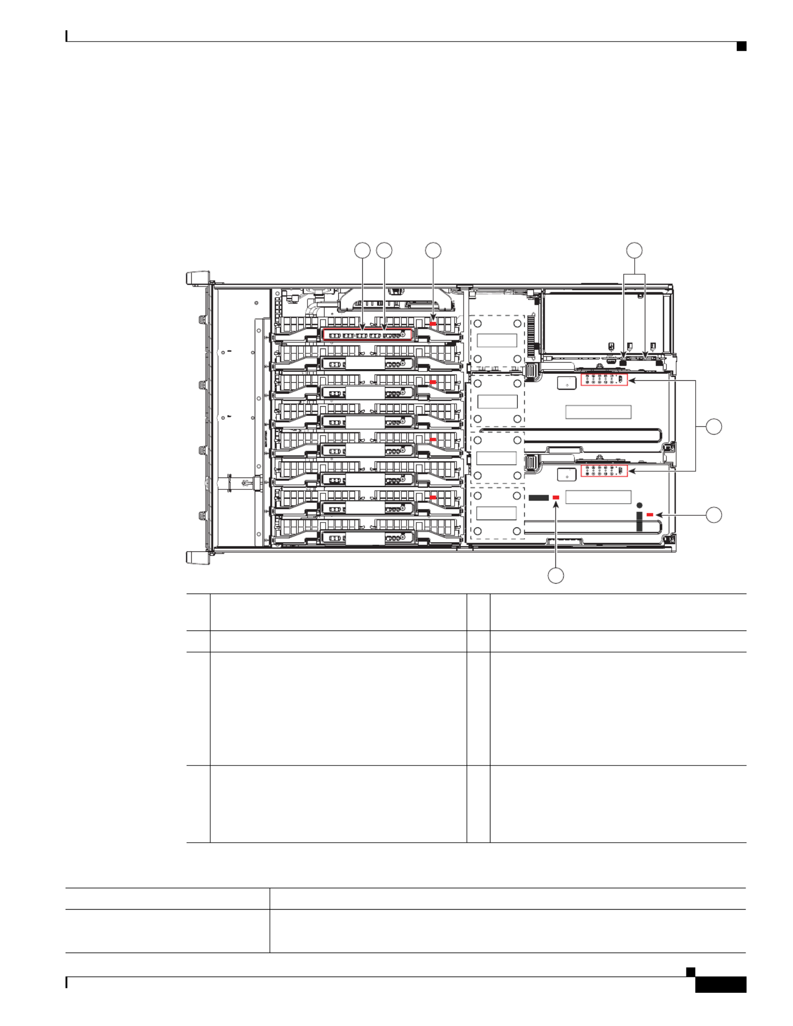
SAS/SATA Drive Population Guidelines
The server can hold up to 12 SAS/SATA hard drives or solid state drives (SSDs). Figure 3-6 shows the
drive bays and the drive bay numbering.
All drive bays support SAS and SATA drives. Drive bays 5 and 9 also support NVMe PCIe SSDs.
Figure 3-6 Drive Bays and Drive Bay Numbering
1 Drive bays 5 and 9
These two bays support NVMe PCIe SSDs
and SAS/SATA drives.
3 Drive bays 3, 4, 6, 7, 8, 10, 11, and 12
When using the Cisco UCS 12G SAS Modular
8-Port RAID Controller (UCSC-MRAID12G),
the 8 SAS/SATA drives must be in these 8 drive
bays.
2 Drive bays 1–12
All bays support SAS and SATA drives.
When using the Cisco UCS 12G SAS
Modular 12-Port RAID Controller
(UCSC-MRAIDC460), you can control all
12 SAS/SATA drives.

3-15
Cisco UCS C460 M4 Server Installation and Service Guide
OL-31215-01
Chapter 3 Maintaining the Server
Replacing Server Components
Observe these drive population guidelines for optimum performance:
•When using the Cisco UCS 12G SAS Modular 12-Port RAID Controller (UCSC-MRAIDC460), you
can control all 12 SAS/SATA drives. You can populate all 12 drive bays with SAS/SATA drives.
•When using the Cisco UCS 12G SAS Modular 8-Port RAID Controller (UCSC-MRAID12G), the
eight SAS/SATA drives must be in bays 3, 4, 6, 7, 8, 10, 11, and 12, as shown in Figure 3-6.
See RAID Controller Cabling, page C-4 for information about cabling for specific bays and how
those bays are grouped.
•Keep an empty drive blanking tray in any unused slots to ensure proper airflow.
•You can mix hard drives and SSDs in the same server. However, you cannot configure a logical
volume (virtual drive) that contains a mix of hard drives and SSDs. When you create a logical
volume, it must contain all hard drives or all SSDs.
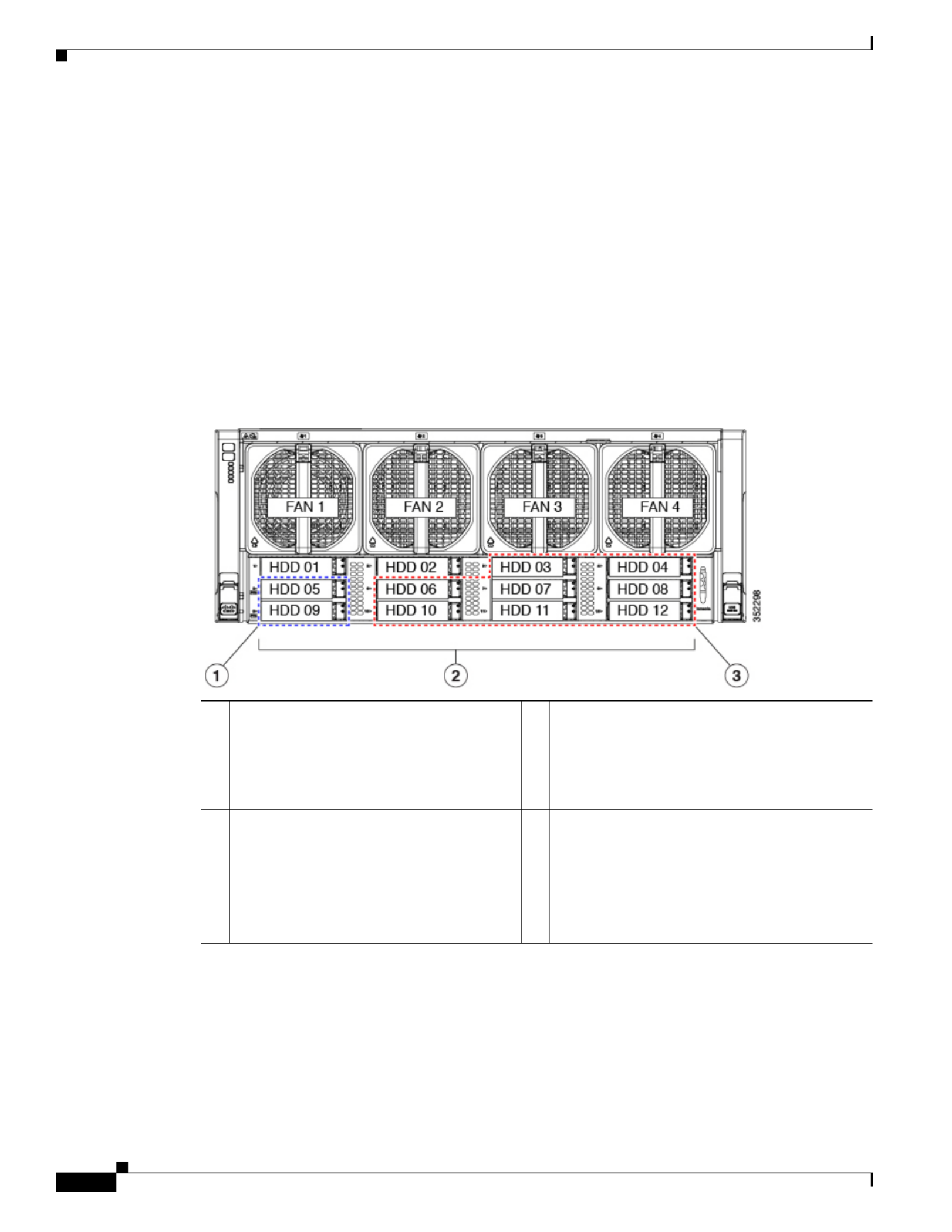
Replacing a SAS or SATA Drive
Tip You do not have to shut down the server or drive to replace SAS/SATA hard drives or SSDs because they
are hot-swappable. To replace an NVMe PCIe SSD drive, which must be shut down before removal, see
Replacing an NVMe PCIe SSD, page 3-17
For information about drive tray LEDs, see Front-Panel LEDs, page 3-2.
Step 1 Remove the drive that you are replacing or remove a blank tray from an empty bay:
a. Remove the front bezel from the server, if one is attached. See Removing or Replacing the Front
Bezel (Optional), page 3-9.
b. Press the release button on the face of the drive tray. See Figure 3-7.
c. Grasp and open the ejector lever and then pull the drive tray out of the slot.
d. If you are replacing an existing drive, remove the four drive tray screws that secure the drive to the
tray and then lift the drive out of the tray.
Step 2 Install a new drive:
a. Place a new drive in the empty drive tray and replace the four drive tray screws.
b. With the ejector lever on the drive tray open, insert the drive tray into the empty drive bay.
c. Push the tray into the slot until it touches the backplane, and then close the ejector lever to lock the
drive in place.
d. Replace the front bezel to the server, if you removed one.
3-16
Cisco UCS C460 M4 Server Installation and Service Guide
OL-31215-01
Chapter 3 Maintaining the Server
Replacing Server Components
Figure 3-7 Removing Drives
1 Release button 3 Drive tray securing screws (4)
2 Ejector lever
FAN 1 FAN 2 FAN 3 FAN 4
HDD 01
HDD 05
HDD 09
HDD 02
HDD 06
HDD 10
HDD 03
HDD 07
HDD 11
HDD 04
HDD 08
HDD 12
352299
2
1
3
3
3
3

3-17
Cisco UCS C460 M4 Server Installation and Service Guide
OL-31215-01
Chapter 3 Maintaining the Server
Replacing Server Components
Replacing an NVMe PCIe SSD
•NVMe PCIe SSD Population Guidelines, page 3-17
•NVMe PCIe SSD Requirements and Restrictions, page 3-17
•Replacing an NVMe PCIe SSD, page 3-17
NVMe PCIe SSD Population Guidelines
Populate NVMe PCIe SSDs only in bays 5 and 9 (see Figure 3-6).
Note Installing two NVMe PCIe SSDs requires four CPUs in the system. You can use only drive bay 5 for
these drives in a two-CPU system (see the table below).
NVMe PCIe SSD Requirements and Restrictions
Observe these restrictions for NVMe PCIe SSDs:
•You cannot boot from an NVMe PCIe SSD.
•You cannot control an NVMe PCIe SSD with a SAS RAID controller because they communicate
with the server via the PCIe bus.
Caution NVMe PCIe SSDs are hot-pluggable, which means that you must shut down the drive before removal,
but you do not have to fully power off the server. To replace a SAS/SATA drive, see Replacing a SAS or
SATA Drive, page 3-15.
Replacing an NVMe PCIe SSD
For information about drive tray LEDs, see Front-Panel LEDs, page 3-2.
Step 1 Shut down the NVMe PCIe SSD. Use your operating system interface to shut down the drive, and then
observe the drive-tray status LED:
•Green—The drive is in use and functioning properly. Do not remove.
•Green, blinking—the driver is unloading following a shutdown command. Do not remove.
•Off—The drive is not in use and can be safely removed.
Step 2 Remove the drive that you are replacing:
a. Remove the front bezel from the server, if one is attached. See Removing or Replacing the Front
Bezel (Optional), page 3-9.
b. Press the release button on the face of the drive tray. See Figure 3-7.
Number of CPUs in
System
NVMe PCIe SSD Drive
Bays Supported
2Bay 5 only
4 Bays 5 and 9

3-18
Cisco UCS C460 M4 Server Installation and Service Guide
OL-31215-01
Chapter 3 Maintaining the Server
Replacing Server Components
c. Grasp and open the ejector lever and then pull the drive tray out of the slot.
d. If you are replacing an existing drive, remove the four drive tray screws that secure the drive to the
tray and then lift the drive out of the tray.
Step 3 Install a new drive:
a. Place a new drive in the empty drive tray and replace the four drive tray screws.
b. With the ejector lever on the drive tray open, insert the drive tray into the empty drive bay.
c. Push the tray into the slot until it touches the backplane, and then close the ejector lever to lock the
drive in place.
Step 4 Observe the drive-tray status LED and wait until it returns to solid green before accessing the drive:
•Off—The drive is not in use.
•Green, blinking—the driver is initializing following hot-plug insertion.
•Green—The drive is in use and functioning properly.
Step 5 Replace the front bezel to the server, if you removed one.

3-19
Cisco UCS C460 M4 Server Installation and Service Guide
OL-31215-01
Chapter 3 Maintaining the Server
Replacing Server Components
Replacing Fan Modules
The four fan modules in the server are numbered as shown in Figure 3-8. You do not have to shut down
or power off the server to replace fan modules because they are hot-swappable.
Tip Each fan module has a fault LED on its face that lights amber if the fan module fails.
Step 1 Remove the fan module that you are replacing (see Figure 3-8):
a. Remove the front bezel from the server, if one is attached. See Removing or Replacing the Front
Bezel (Optional), page 3-9.
b. Grasp the handle on the front of the fan module while depressing the release button with your thumb.
c. Pull the fan module straight out of the bay.
Step 2 Install a new fan module:
a. Grasp the fan module by its handle and align it with the empty fan bay.
b. Push the fan module straight into the bay until the release button clicks to lock the fan module in
place.
c. Replace the front bezel to the server, if you removed one.
Figure 3-8 Fan Modules
1 Fan module handle 2 Fan module release button
FAN 1 FAN 2 FAN 3 FAN 4
HDD 01
HDD 05
HDD 09
HDD 02
HDD 06
HDD 10
HDD 03
HDD 07
HDD 11
HDD 04
HDD 08
HDD 12
352300
1
3
2

3-20
Cisco UCS C460 M4 Server Installation and Service Guide
OL-31215-01
Chapter 3 Maintaining the Server
Replacing Server Components
Replacing Memory Risers
Caution DDR4 memory risers are available for use with DDR4 DIMMs and EX v3 CPUs. You must upgrade to
Cisco IMC 2.0(6) or later firmware before you upgrade the hardware. See Special Information For
Upgrades to Intel Xeon v3 Series CPUs, page 3-29.
The 8 memory risers connect to motherboard sockets and each riser provides 12 DIMM slots. Each riser
has two memory buffers, each with two DDR channels of three DIMMs. The memory riser is
hot-pluggable when you use the Attention button to take the riser offline, as described in the procedure
in this section. (This feature is available only on supported operating systems. Some operating systems
support only hot-add, but not hot-remove.)
Note See the release notes for your operating system and your Cisco IMC/BIOS release for details and
restrictions on hot-plugging: Cisco IMC Release Notes.
Figure 3-9 Memory Riser LEDs (Top View)
Memory Riser Population Guidelines
Use the following guidelines when populating memory risers:
•Each CPU supports two memory risers.
•The minimum memory riser configuration is one riser installed on CPU1 or CPU2, with at least one
DIMM. The minimum DIMM capacity must meet the requirements of the OS installed.
•If not installing all memory risers, populate the even-numbered riser slots first to ensure optimum
CPU airflow.
1 Attention button (used for hot-plugging) 4 Mirror activity LED (lights when memory
mirroring is enabled in the BIOS)
2 Power LED (indicates when the riser has
power)
5 Memory riser fault LED (indicates when the
memory riser has failed)
3 Attention LED (indicates when hot-plugging
is safe)
6 DIMM fault LEDs (indicate which DIMM on
the riser has failed)
352301
1 2 3 4 5 6

3-21
Cisco UCS C460 M4 Server Installation and Service Guide
OL-31215-01
Chapter 3 Maintaining the Server
Replacing Server Components
Identifying a Faulty Memory Riser or DIMM
The memory riser includes fault LEDs on its top panel (see Figure 3-9):
•If the memory riser fault LED is lit, replace the memory riser as described in Replacing a Memory
Riser, page 3-21.
•If one or more of the numbered DIMM fault LEDs are lit, replace the corresponding DIMMs on the
riser as described in Replacing DIMMs, page 3-23.
Replacing a Memory Riser
The qualified and supported part numbers for this component are subject to change over time. For the most
up-to-date list of replaceable components, see the following URL and then scroll to Technical Specifications:
http://www.cisco.com/en/US/products/ps10493/products_data_sheets_list.html
Step 1 Remove the memory riser that you are replacing (see Figure 3-10):
a. Slide the server out the front of the rack far enough so that you can remove the top cover.
b. Remove the top cover as described in Removing or Replacing the Server Top Cover, page 3-10.
Caution Memory risers are hot-pluggable, which means that you do not have to remove power from the server,
but you must shut down the riser before removing it as described in the following steps.
c. Press the attention button on the top of the memory riser to shut down the riser in the BIOS (see
Figure 3-9).
d. Wait until the attention LED (ATTN) and the power LED (PWR) turn off.
e. Press both green riser-latch release buttons on the top of the riser (see Figure 3-10).
f. Lift on both riser latches at the same time. The lever action disengages the riser’s connector from
the motherboard socket.
g. Grasp the open retaining latches and lift the memory riser straight up and out of the server.
h. To remove DIMMs from the memory riser, use the instructions in Replacing DIMMs, page 3-23.
Step 2 Install a new memory riser:
Note When you install more than one memory riser, you must install and activate one riser at a time before
you install and activate the next riser. That is, do not attempt to install all risers and then activate them.
a. To install DIMMs to the new memory riser, use the instructions in Replacing DIMMs, page 3-23.
b. Ensure that the riser retaining latches are in the open position.
c. Align the riser with the empty motherboard socket and the card guides at each end of the riser (on
the chassis mid-brace and the rear of the fan cage).
d. Lower the riser until it makes contact with the motherboard socket.
e. Close each retaining latch at the same time to fully engage the riser with the motherboard socket.
f. Press the attention button on the top of the memory riser (see Figure 3-9), and then wait until the
attention LED (ATTN) turns off and the power LED (PWR) turns on.
g. If you have more memory risers to install, follow steps a. through f. for each riser.

3-22
Cisco UCS C460 M4 Server Installation and Service Guide
OL-31215-01
Chapter 3 Maintaining the Server
Replacing Server Components
h. Replace the top cover.
i. Replace the server in the rack.
Figure 3-10 Removing Memory Risers
1 Riser-latch release buttons (two on each riser) 2 Riser retaining latches (two on each riser)
352302
CPU1
MEM 1
MEM 2
MEM 3
MEM 4
MEM 5
MEM 6
MEM 7
MEM 8
CPU2
CPU3
CPU4
PCIe Riser 1
PCIe Riser 2
1
2
3-23
Cisco UCS C460 M4 Server Installation and Service Guide
OL-31215-01
Chapter 3 Maintaining the Server
Replacing Server Components
Replacing DIMMs
Caution DDR4 DIMMs are available for use with DDR4 memory risers and EX v3 CPUs. You must upgrade to Cisco
IMC 2.0(6) or later firmware before you upgrade the hardware. See Special Information For Upgrades to Intel
Xeon v3 Series CPUs, page 3-29.
This section includes the following topics:
•DIMM Performance Guidelines and Population Rules, page 3-23
•Replacing a DIMM, page 3-28
Caution DIMMs and their sockets are fragile and must be handled with care to avoid damage during installation.
Caution Cisco does not support thir sco DIMMs in the server might result in system d-party DIMMs. Using non-Ci
problems or damage to the motherboard.
Note To ensure the best server performance, it is important that you are familiar with memory performance
guidelines and population rules before you install or replace the memory.
DIMM Performance Guidelines and Population Rules
This section describes the type of memory that the server requires and its effect on performance. The section
includes the following topics:
•DIMM Sockets, page 3-23
•DIMM Population Rules, page 3-24
•Memory Mirroring Mode, page 3-27
•Lockstep Channel Mode, page 3-27
DIMM Sockets
Figure 3-11 shows the DIMM sockets and how they are numbered on a memory riser.
•Each memory riser has 12 DDR3 DIMM sockets.
•Channels are labeled with letters as shown in Figure 3-11. For example, channel A = DIMM slots A1, A2,
A3.
•Each channel has three DIMM sockets. The blue socket in a channel is always socket 1.

3-24
Cisco UCS C460 M4 Server Installation and Service Guide
OL-31215-01
Chapter 3 Maintaining the Server
Replacing Server Components
Figure 3-11 DIMM Sockets on a Memory Riser
DIMM Population Rules
Observe the following guidelines when installing or replacing DIMMs:
•The minimum configuration without memory mirroring is one memory riser installed on a slot for
CPU1 or CPU2, with one DIMM. The minimum DIMM capacity must meet the requirements of the
OS installed.
•The minimum configuration with memory mirroring is one memory riser installed on a slot for
CPU1 or CPU2, with two matched DIMM pairs. A matched DIMM pair is two DIMMs with the
same Cisco part number (same capacity, same rank, and same buffer type (RDIMM or LRDIMM)).
•For optimal performance, spread DIMMs evenly across all CPUs and DDR channels.
•Any DIMM installed in a memory riser that corresponds to an empty CPU slot is inaccessible. In a
two-CPU server, memory risers 5–8 are not available.
•Populate the DIMM 1 slots on a riser first, then the DIMM 2 slots, then the DIMM 3 slots. For
example, populate the DIMM slots on a riser in this order:
1. A1, C1, B1, D1
2. A2, C2, B2, D2
3. A3, C3, B3, D3
•See the following tables for the recommended population order for optimum performance.
–
Table 3-4: Two-CPU/four-riser system
–
Table 3-5: Four-CPU/eight-riser system
•Do not mix RDIMMs and LRDIMMs.
•NVIDIA GPUs can support only less than 1 TB of memory in the server. Therefore, do not install
1 TB or more total memory when using an NVIDIA GPU card in this server.
352303
B1
B2
B3
A1
A2
A3
D1
D2
D3
C1
C2
C3

3-25
Cisco UCS C460 M4 Server Installation and Service Guide
OL-31215-01
Chapter 3 Maintaining the Server
Replacing Server Components
Table 3-4 describes the recommended population order for a two-CPU system that has four memory
risers. In a two-CPU system, only CPU1 and CPU2 are populated. Only the memory risers controlled by
CPU1 and CPU2 (MEM1, MEM2, MEM3, and MEM4) are populated.
Table 3-4 DIMM Population for Two-CPU/Four-Riser System Optimum Performance
No. of
DIMMs
Installed CPU Riser
DIMM
Socket
No. of
DIMMs
Installed CPU Riser
DIMM
Socket
First: 1 CPU1 1 A1 25 CPU1 1 B2
2 CPU2 3 A1 26 CPU2 3 B2
3 CPU1 2 A1 27 CPU1 2 B2
4 CPU2 4 A1 28 CPU2 4 B2
5 CPU1 1 C1 29 CPU1 1 D2
6 CPU2 3 C1 30 CPU2 3 D2
7 CPU1 2 C1 31 CPU1 2 D2
8 CPU2 4 C1 32 CPU2 4 D2
9 CPU1 1 B1 33 CPU1 1 A3
10 CPU2 3 B1 34 CPU2 3 A3
11 CPU1 2 B1 35 CPU1 2 A3
12 CPU2 4 B1 36 CPU2 4 A3
13 CPU1 1 D1 37 CPU1 1 C3
14 CPU2 3 D1 38 CPU2 3 C3
15 CPU1 2 D1 39 CPU1 2 C3
16 CPU2 4 D1 40 CPU2 4 C3
17 CPU1 1 A2 41 CPU1 1 B3
18 CPU2 3 A2 42 CPU2 3 B3
19 CPU1 2 A2 43 CPU1 2 B3
20 CPU2 4 A2 44 CPU2 4 B3
21 CPU1 1 C2 45 CPU1 1 D3
22 CPU2 3 C2 46 CPU2 3 D3
23 CPU1 2 C2 47 CPU1 2 D3
24 CPU2 4 C2 Last: 48 CPU2 4 D3

3-26
Cisco UCS C460 M4 Server Installation and Service Guide
OL-31215-01
Chapter 3 Maintaining the Server
Replacing Server Components
Table 3-5 describes the recommended population order for a four-CPU system that has eight memory
risers.
Table 3-5 DIMM Population For Four-CPU/Eight-Riser System Optimum Performance
No. of
DIMMs
Installed CPU Riser
DIMM
Socket
No. of
DIMMs
Installed CPU Riser
DIMM
Socket
No. of
DIMMs
Installed CPU Riser
DIMM
Socket
No. of
DIMMs
Installed CPU Riser
DIMM
Socket
First: 1 CPU1 1 A1 25 CPU1 1 D1 49 CPU1 1 B2 73 CPU1 1 C3
2 CPU2 3 A1 26 CPU2 3 D1 50 CPU2 3 B2 74 CPU2 3 C3
3 CPU3 5 A1 27 CPU3 5 D1 51 CPU3 5 B2 75 CPU3 5 C3
4 CPU4 7 A1 28 CPU4 7 D1 52 CPU4 7 B2 76 CPU4 7 C3
5 CPU1 2 A1 29 CPU1 2 D1 53 CPU1 2 B2 77 CPU1 2 C3
6 CPU2 4 A1 30 CPU2 4 D1 54 CPU2 4 B2 78 CPU2 4 C3
7 CPU3 6 A1 31 CPU3 6 D1 55 CPU3 6 B2 79 CPU3 6 C3
8 CPU4 8 A1 32 CPU4 8 D1 56 CPU4 8 B2 80 CPU4 8 C3
9 CPU1 1 C1 33 CPU1 1 A2 57 CPU1 1 D2 81 CPU1 1 B3
10 CPU2 3 C1 34 CPU2 3 A2 58 CPU2 3 D2 82 CPU2 3 B3
11 CPU3 5 C1 35 CPU3 5 A2 59 CPU3 5 D2 83 CPU3 5 B3
12 CPU4 7 C1 36 CPU4 7 A2 60 CPU4 7 D2 84 CPU4 7 B3
13 CPU1 2 C1 37 CPU1 2 A2 61 CPU1 2 D2 85 CPU1 2 B3
14 CPU2 4 C1 38 CPU2 4 A2 62 CPU2 4 D2 86 CPU2 4 B3
15 CPU3 6 C1 39 CPU3 6 A2 63 CPU3 6 D2 87 CPU3 6 B3
16 CPU4 8 C1 40 CPU4 8 A2 64 CPU4 8 D2 88 CPU4 8 B3
17 CPU1 1 B1 41 CPU1 1 C2 65 CPU1 1 A3 89 CPU1 1 D3
18 CPU2 3 B1 42 CPU2 3 C2 66 CPU2 3 A3 90 CPU2 3 D3
19 CPU3 5 B1 43 CPU3 5 C2 67 CPU3 5 A3 91 CPU3 5 D3
20 CPU4 7 B1 44 CPU4 7 C2 68 CPU4 7 A3 92 CPU4 7 D3
21 CPU1 2 B1 45 CPU1 2 C2 69 CPU1 2 A3 93 CPU1 2 D3
22 CPU2 4 B1 46 CPU2 4 C2 70 CPU2 4 A3 94 CPU2 4 D3
23 CPU3 6 B1 47 CPU3 6 C2 71 CPU3 6 A3 95 CPU3 6 D3
24 CPU4 8 B1 48 CPU4 8 C2 72 CPU4 8 A3 Last: 96 CPU4 8 D3

3-27
Cisco UCS C460 M4 Server Installation and Service Guide
OL-31215-01
Chapter 3 Maintaining the Server
Replacing Server Components
Memory Mirroring Mode
When you enable memory mirroring mode in the server BIOS, the memory subsystem simultaneously
writes identical data to two channels. If a memory read from one of the channels returns incorrect data
due to an uncorrectable memory error, the system automatically retrieves the data from the other
channel. A transient or soft error in one channel does not affect the mirrored data, and operation
continues.
Memory mirroring reduces the amount of memory available to the operating system by 50 percent
because only one of the two populated channels provides data.
Lockstep Channel Mode
In this mode, the main memory channel from the CPU to the memory buffer runs at the same clock rate
of each of the two memory subchannels from the buffer to the DIMMs, and both DIMM subchannels are
accessed simultaneously for a double-width access. For example, if the CPU channel clock speed is 1600
MHz, each of the DIMM subchannels operates at 1600 MHz. For this reason, lockstep mode is referred
to as 1:1. Memory lockstep mode provides protection against both single-bit and multi-bit errors.
Memory lockstep allows two memory channels to work as a single channel, moving a data word two
channels wide and providing eight bits of memory correction.
Lockstep channel mode requires that all four memory channels on a CPU must be populated identically
with regards to size and organization. DIMM socket populations within a channel do not have to be
identical but the same DIMM slot location across all four channels must be populated the same.
For example, DIMMs in sockets A1, B1, C1, and D1 must be identical. DIMMs in sockets A2, B2, C2,
and D2 must be identical. However, the A1-B1-C1-D1 DIMMs do not have to be identical with the
A2-B2-C2-D2 DIMMs.

3-28
Cisco UCS C460 M4 Server Installation and Service Guide
OL-31215-01
Chapter 3 Maintaining the Server
Replacing Server Components
Replacing a DIMM
This section includes the following topics:
•Identifying a Faulty Memory Riser or DIMM, page 3-28
•Replacing DIMMs, page 3-28
Identifying a Faulty Memory Riser or DIMM
The memory riser includes fault LEDs on its top panel (see Figure 3-9).
•If the riser fault LED is lit, replace the memory riser as described Replacing a Memory Riser,
page 3-21.
•If one or more of the numbered DIMM fault LEDs are lit, replace the corresponding DIMMs as
described in Replacing DIMMs, page 3-23.
Replacing DIMMs
Step 1 Remove the DIMMs that you are replacing:
a. Slide the server out the front of the rack far enough so that you can remove the top cover.
Caution If you cannot safely view and access the component, remove the server from the rack.
b. Remove the top cover as described in Removing or Replacing the Server Top Cover, page 3-10.
Caution Memory risers are hot-pluggable, which means that you do not have to remove power from the server,
but you must shut down the riser before removing it.
c. Locate the memory riser that has the faulty DIMM, and then shut down and remove the riser as
described in Replacing Memory Risers, page 3-20.
d. Locate the faulty DIMM and remove it from the socket on the riser by opening the ejector levers at
both ends of the DIMM socket.
Step 2 Install a new DIMM:
Note Before installing DIMMs, refer to the population guidelines. See DIMM Performance
Guidelines and Population Rules, page 3-23.
a. Align the new DIMM with the socket on the riser. Use the alignment key in the DIMM socket to
correctly orient the DIMM.
b. Push the DIMM into the socket until it is fully seated and the ejector levers on either side of the
socket lock into place.
c. Replace the memory riser to its motherboard socket and bring it back online by using the procedure
in Replacing Memory Risers, page 3-20.
d. Replace the top cover.

3-29
Cisco UCS C460 M4 Server Installation and Service Guide
OL-31215-01
Chapter 3 Maintaining the Server
Replacing Server Components
Replacing CPUs and Heat Sinks
Caution Xeon v3 Series CPUs are available for use with DDR4 memory risers and DDR4 DIMMs. You must
upgrade to Cisco IMC 2.0(6) or later firmware before you upgrade the hardware. See Special
Information For Upgrades to Intel Xeon v3 Series CPUs, page 3-29.
This section contains the following topics:
•Special Information For Upgrades to Intel Xeon v3 Series CPUs, page 3-29
•CPU Configuration Rules, page 3-30
•Replacing a CPU and Heat Sink, page 3-30
•Additional CPU-Related Parts to Order with RMA Replacement Motherboards, page 3-36
Special Information For Upgrades to Intel Xeon v3 Series CPUs
Caution You must upgrade your server firmware to the required minimum level before you upgrade to v3 Series
CPUs. Older firmware versions cannot recognize the new CPUs and this results in a non-bootable server.
Caution Intel Xeon v3 Series CPUs require DDR4 memory risers and DDR4 DIMMs to operate.
The minimum software and firmware versions required for the server to support Intel E7-4800 or
E7-8800 v3 Series CPUs are as follows:
Do one of the following actions:
•If your server’s firmware and/or Cisco UCS Manager software are already at the required levels
shown in Table 3-6, you can install the CPU hardware by using the procedure in this section.
•If your server’s firmware and/or Cisco UCS Manager software is earlier than the required levels, use
the instructions in the Cisco UCS C-Series Servers Upgrade Guide for Intel Xeon v3 Series CPUs
to upgrade your firmware. After you upgrade, return to the procedure in this section to install the
CPU and heatsink hardware.
Table 3-6 Minimum Requirements For Intel Xeon v3 Series CPUs
Software or Firmware Minimum Version
Server CIMC 2.0(6)
Server BIOS 2.0(6)
Low-level server firmware Updated automatically when Cisco IMC is updated using
Cisco Host Upgrade Utility or Cisco UCS Manager.
Otherwise, check for “update available” message as
described in the Cisco UCS C-Series Servers Upgrade
Guide for Intel Xeon v3 Series CPUs.
Cisco UCS Manager
(required only for Cisco UCS
Manager-integrated system)
2.2(5)

3-30
Cisco UCS C460 M4 Server Installation and Service Guide
OL-31215-01
Chapter 3 Maintaining the Server
Replacing Server Components
CPU Configuration Rules
The server supports two or four CPUs. See Figure 3-11 on page 3-24 for the CPU socket numbering.
•The minimum configuration is two identical CPUs (CPU1 and CPU2).
•The server must have either two or four identical CPUs to operate; populate CPU1 and CPU2 first,
then populate CPU3 and CPU4.
•In a two-CPU server (CPU1 and CPU2), the following components are not available because they
require CPU3 and CPU4 to be installed:
–
PCIe riser 2 (PCIe slots 6–10)
–
Memory risers 5–8
Caution In a two-CPU system, you must have the CPU filler panel installed in place of CPU3 and CPU4 to
maintain correct airflow and cooling.
Replacing a CPU and Heat Sink
Caution CPUs and their motherboard sockets are fragile and must be handled with care to avoid damaging pins
during installation. The CPUs must be installed with heat sinks and their thermal pads to ensure proper
cooling. Failure to install a CPU correctly might result in damage to the server.
Caution The Intel Pick-n-Place tools used in this procedure are required to prevent damage to the contact pins
between the motherboard and the CPU. Do not attempt this procedure without the required tools, which
are included with each CPU option kit. If you do not have the tool, you can order a spare (Cisco PID
UCS-CPU-EP-PNP=).
Step 1 Prepare the server for replacement:
a. Power off the server as described in Shutting Down and Powering Off the Server, page 3-8.
b. Slide the server out the front of the rack far enough so that you can remove the top cover.
Caution If you cannot safely view and access the component, remove the server from the rack.
c. Remove the top cover as described in Removing or Replacing the Server Top Cover, page 3-10.

3-31
Cisco UCS C460 M4 Server Installation and Service Guide
OL-31215-01
Chapter 3 Maintaining the Server
Replacing Server Components
Step 2 Provide clearance for removing the CPU:
a. Remove all memory risers from the server.
With power removed from the server, you do not have to shut down the memory risers before
removal. Press both green riser-latch release buttons on the top of the riser (see Figure 3-10), and
then lift on both riser latches at the same time.
Note It is important that each memory riser is returned to the same slot it was removed from to
maintain your DIMM configuration. Label the risers or organize them in order as you remove
them and set them aside on an antistatic surface.
b. Remove both PCIe risers from the server.
Lift on the retaining latch at the top of the riser until it is vertical (see Figure 3-19).
c. Remove the chassis mid-brace (see Figure 3-5 on page 3-11).
Note The securing mechanism for the mid-brace differs, depending on when the system was produced.
–
Older systems have a spring-loaded plunger that secures each end of the mid-brace. Access
these plungers on the inside of the chassis. Pull inward on the spring-loaded plunger that secures
each end of the mid-brace, then lift straight up.
–
Newer systems have two screws that secure each end of the mid-brace. Access these screws on
the outside of the chassis. Remove the two screws at each end of the mid-brace, then lift straight
up.
Step 3 Use a Number 2 Phillips-head screwdriver to loosen the four captive screws that secure the heat sink,
and then lift it off of the CPU.
Note Loosen each screw evenly to avoid damaging the heat sink or CPU.
Step 4 Unclip the first CPU retaining latch that is labeled with the icon, and then unclip the second
retaining latch that is labeled with the icon. See Figure 3-12.
Note You must hold the first retaining latch open before you can lift the second retaining latch.
Step 5 Open the hinged CPU cover plate. See Figure 3-12.

3-32
Cisco UCS C460 M4 Server Installation and Service Guide
OL-31215-01
Chapter 3 Maintaining the Server
Replacing Server Components
Figure 3-12 CPU Socket Retaining Latches
Step 6 Remove a protective cap from the socket (if present).
If you are installing a new CPU to a socket that was shipped empty, the socket has a protective cap that
is intended to prevent bent contact pins. If you are removing an old CPU instead, skip to Step 7.
Caution If you are adding CPUs to a server that previously had only two CPUs, remove the CPU filler panels and
the PCIe filler panel, if present, to ensure correct airflow and cooling.
Step 7 Remove the old CPU:
a. Set the Pick-n-Place tool on the CPU in the socket, aligning the arrow on the tool with the
registration mark on the socket (the small triangular mark). See Figure 3-13.
b. Press the top button on the tool to grasp the installed CPU.
c. Lift the tool and CPU straight up.
d. Press the top button on the tool to release the old CPU on an antistatic surface.
1 3CPU retaining latch, Hinged CPU cover plate
2CPU retaining latch,
1
3
2
332093

3-33
Cisco UCS C460 M4 Server Installation and Service Guide
OL-31215-01
Chapter 3 Maintaining the Server
Replacing Server Components
Figure 3-13 Pick-n-Place Tool
Step 8 Insert the new CPU into the Pick-n-Place tool:
a. Remove the new CPU from the packaging and place it on the pedestal that is included in the kit.
Align the registration mark on the corner of the CPU with the arrow on the corner of the pedestal
(see Figure 3-14).
b. Press down on the top button of the tool to lock it open.
c. Set the Pick-n-Place tool on the CPU pedestal, aligning the arrow on the tool with the arrow on the
corner of the pedestal. Make sure that the tabs on the tool are fully seated in the slots on the pedestal.
d. Press down on the top button of the tool to grasp and lock in the CPU.
e. Lift the tool and CPU straight up off the pedestal.
1Arrow on tool 2Registration mark on CPU socket
352315
1
2

3-64
Cisco UCS C460 M4 Server Installation and Service Guide
OL-31215-01
Chapter 3 Maintaining the Server
Replacing Server Components
Enabling the Intel TXT Feature in the BIOS
Intel Trusted Execution Technology (TXT) provides greater protection for information that is used and
stored on the business server. A key aspect of that protection is the provision of an isolated execution
environment and associated sections of memory where operations can be conducted on sensitive data,
invisibly to the rest of the system. Intel TXT provides for a sealed portion of storage where sensitive data
such as encryption keys can be kept, helping to shield them from being compromised during an attack
by malicious code.
Step 1 Reboot the server and watch for the prompt to press F2.
Step 2 When prompted, press F2 to enter the BIOS Setup utility.
Step 3 Verify that the prerequisite BIOS values are enabled:
a. Choose the Advanced tab.
b. Choose Intel TXT(LT-SX) Configuration to open the Intel TXT(LT-SX) Hardware Support
window.
c. Verify that the following items are listed as Enabled:
–
VT-d Support (default is Enabled)
–
VT Support (default is Enabled)
–
TPM Support
–
TPM State
•If VT-d Support and VT Support are already enabled, skip to Step 4.
•If VT-d Support and VT Support are not enabled, continue with the next steps to enable them.
d. Press Escape to return to the BIOS Setup utility Advanced tab.
e. On the Advanced tab, choose Processor Configuration to open the Processor Configuration
window.
f. Set Intel (R) VT and Intel (R) VT-d to Enabled.
Step 4 Enable the Intel Trusted Execution Technology (TXT) feature:
a. Return to the Intel TXT(LT-SX) Hardware Support window if you are not already there.
b. Set TXT Support to Enabled.
Step 5 Press F10 to save your changes and exit the BIOS Setup utility.

3-65
Cisco UCS C460 M4 Server Installation and Service Guide
OL-31215-01
Chapter 3 Maintaining the Server
Replacing Server Components
Replacing Power Supplies
The server requires four 1400 W power supplies. When four power supplies are installed they are
redundant as 2+2.
Note If you have ordered a server with power supply redundancy (four power supplies), you do not have to
power off the server to replace power supplies because they are redundant as 2+2.
Step 1 Remove the power supply that you are replacing or a blank panel from an empty bay (see Figure 3-28):
a. Perform one of the following actions:
–
If your server has only two power supplies, shut down and power off the server as described in
Shutting Down and Powering Off the Server, page 3-8.
–
If your server has four power supplies, you do not have to power off the server.
b. Remove the power cord from the power supply that you are replacing.
c. Grasp the power supply handle while pinching the release lever toward the handle.
d. Pull the power supply out of the bay.
Step 2 Install a new power supply:
a. Grasp the power supply handle and insert the new power supply into the empty bay.
b. Push the power supply into the bay until the release lever locks.
c. Connect the power cord to the new power supply.
d. If you powered off the server, press the Power button to return the server to main power mode.
Figure 3-28 Removing and Replacing Power Supplies
1 Power supply handle 2 Power supply release lever
352324
PSU 1
PCIe 6
Riser 2
Riser 1
PCIe 7
PCIe 8
PCIe 9
PCIe 10
PSU 2
PSU 3
PSU 4
PCIe 1
PCIe 2
PCIe 3
PCIe 4
PCIe 5
1 2

3-66
Cisco UCS C460 M4 Server Installation and Service Guide
OL-31215-01
Chapter 3 Maintaining the Server
Service DIP Switches
Service DIP Switches
This server includes a dual in-line package (DIP) switch panel on the media riser card.
This section includes the following topics:
•DIP Switch Location on the Media Riser Card, page 3-66
•Using the Clear Password DIP Switch, page 3-67
•Using the BIOS Recovery DIP Switch, page 3-68
•Using the Clear CMOS DIP Switch, page 3-69
DIP Switch Location on the Media Riser Card
The panel of DIP switches is located on the media riser card (see Figure 3-29). The default position for
all switches is open (down). See Table 3-11 for definitions of the supported switch functions.
The media riser is the removable card that also includes the Cisco Flexible Flash drive (SD card) bays
and the internal USB slot. See Figure 3-26 on page 3-58 for the location of the media riser in the server.
Figure 3-29 DIP Switches on the Media Riser Card
1DIP switch panel on the media riser card
Switches are shown in the open (down) position.
–
Table 3-11 Supported DIP Switch Functions
Switch Number Function
1 Clear Password
2 Recover BIOS
3 Clear CMOS
4–8 Reserved
1
352467
1 2 3 4 5 6 7 8

3-67
Cisco UCS C460 M4 Server Installation and Service Guide
OL-31215-01
Chapter 3 Maintaining the Server
Service DIP Switches
Using the Clear Password DIP Switch
You can use DIP switch #1 to clear the BIOS administrator password.
Step 1 Power off the server as described in Shutting Down and Powering Off the Server, page 3-8.
Step 2 Disconnect all power cords from the power supplies.
Step 3 Slide the server out the front of the rack far enough so that you can remove the top cover.
Caution If you cannot safely view and access the component, remove the server from the rack.
Step 4 Remove the top cover as described in Removing or Replacing the Server Top Cover, page 3-10.
Step 5 Locate the media riser card in the server. See Figure 3-26 on page 3-58.
Step 6 Remove PCIe riser 1 from the server to provide clearance. See Replacing a PCIe Riser, page 3-43.
Step 7 Locate the BIOS recovery DIP switch 1 on the media riser card. See Figure 3-29.
Step 8 Use a small pointed object such as a screwdriver to move DIP switch 1 to the closed (upper) position.
Step 9 Reconnect AC power cords to the server. The server powers up to standby power mode.
Step 10 Return the server to main power mode by pressing the Power button on the front panel.
Step 11 After the server has fully booted, power off the server again and disconnect all power cords.
Step 12 Move DIP switch 1 back to the default open (lower) position.
Note If you do not move the switch back to the default position, the Cisco IMC clears the password
each time that you boot the server.
Step 13 Replace PCIe riser 1 to the server. See Replacing a PCIe Riser, page 3-43.
Step 14 Replace the top cover, replace the server in the rack, replace power cords and any other cables, and then
power on the server by pressing the Power button.
3-68
Cisco UCS C460 M4 Server Installation and Service Guide
OL-31215-01
Chapter 3 Maintaining the Server
Service DIP Switches
Using the BIOS Recovery DIP Switch
You can use DIP switch #2 to recover a corrupted BIOS.
Step 1 Download the BIOS update package and extract it to a temporary location.
Step 2 Copy the contents of the extracted recovery folder to the root directory a USB thumb drive.
Step 3 Power off the server as described in Shutting Down and Powering Off the Server, page 3-8.
Step 4 Disconnect all power cords from the power supplies.
Step 5 Slide the server out the front of the rack far enough so that you can remove the top cover.
Caution If you cannot safely view and access the component, remove the server from the rack.
Step 6 Remove the top cover as described in Removing or Replacing the Server Top Cover, page 3-10.
Step 7 Locate the media riser card in the server. See Figure 3-26 on page 3-58.
Step 8 Remove PCIe riser 1 from the server to provide clearance. See Replacing a PCIe Riser, page 3-43.
Step 9 Locate the BIOS recovery DIP switch 2 on the media riser card. See Figure 3-29.
Step 10 Use a small pointed object such as a screwdriver to move DIP switch 2 to the closed (upper) position.
Step 11 Reconnect AC power cords to the server. The server powers up to standby power mode.
Step 12 Insert the USB thumb drive that you prepared in Step 2 into a USB port on the server.
Step 13 Return the server to main power mode by pressing the Power button on the front panel.
The server boots with the updated BIOS boot block.
Step 14 Wait for the server to complete the BIOS update, and then remove the USB thumb drive from the server.
Note During the BIOS update, the Cisco IMC shuts down the server and the window is blank for about
10 minutes. Do not unplug the power cords during this update. The Cisco IMC will power on the
server after the update is complete.
Step 15 After the server has fully booted, power off the server again and disconnect all power cords.
Step 16 Move DIP switch 2 back to the default open (lower) position.
Note If you do not move the switch back to the default position, the Cisco IMC attempts to recover
the BIOS each time that you boot the server.
Step 17 Replace PCIe riser 1 to the server. See Replacing a PCIe Riser, page 3-43.
Step 18 Replace the top cover, replace the server in the rack, replace power cords and any other cables, and then
power on the server by pressing the Power button.

3-69
Cisco UCS C460 M4 Server Installation and Service Guide
OL-31215-01
Chapter 3 Maintaining the Server
Service DIP Switches
Using the Clear CMOS DIP Switch
You can use DIP switch #3 to clear the CMOS settings.
Step 1 Power off the server as described in Shutting Down and Powering Off the Server, page 3-8.
Step 2 Disconnect all power cords from the power supplies.
Step 3 Slide the server out the front of the rack far enough so that you can remove the top cover.
Caution If you cannot safely view and access the component, remove the server from the rack.
Step 4 Remove the top cover as described in Removing or Replacing the Server Top Cover, page 3-10.
Step 5 Locate the media riser card in the server. See Figure 3-26 on page 3-58.
Step 6 Remove PCIe riser 1 from the server to provide clearance. See Replacing a PCIe Riser, page 3-43.
Step 7 Locate the BIOS recovery DIP switch 3 on the media riser card. See Figure 3-29.
Step 8 Use a small pointed object such as a screwdriver to move DIP switch 3 to the closed (upper) position.
Step 9 Reconnect AC power cords to the server. The server powers up to standby power mode.
Step 10 Return the server to main power mode by pressing the Power button on the front panel.
Step 11 After the server has fully booted, power off the server again and disconnect all power cords.
Step 12 Move DIP switch 3 back to the default open (lower) position.
Note If you do not move the switch back to the default position, the Cisco IMC clears the CMOS
settings each time that you boot the server.
Step 13 Replace PCIe riser 1 to the server. See Replacing a PCIe Riser, page 3-43.
Step 14 Replace the top cover, replace the server in the rack, replace power cords and any other cables, and then
power on the server by pressing the Power button.

3-70
Cisco UCS C460 M4 Server Installation and Service Guide
OL-31215-01
Chapter 3 Maintaining the Server
Service DIP Switches

A-2
Cisco UCS C460 M4 Server Installation and Service Guide
OL-22326-01
Appendix A Server Specifications
Environmental Specifications
Environmental Specifications
Table A-2 lists the environmental specifications for the server.
Power Specifications
Table A-3 lists the specifications for each 1400 W power supply
(Cisco part number UCSC-PSU2-1400).
You can get more specific power information for your exact server configuration by using the Cisco UCS
Power Calculator:
http://ucspowercalc.cisco.com
Table A-2 Environmental Specifications
Description Specification
Temperature, operating 5ºC to 35ºC (41ºF to 95ºF)
Temperature, nonoperating –40ºC to 65ºC (–40ºF to 149ºF)
Humidity, operating 10% to 90%
Humidity, nonoperating 5% to 93%
Altitude, operating
Derated 1ºC for each 305 m
0 m to 3048 m (0 ft to 10,000 ft)
Altitude, nonoperating 0 m to 12,192 m (0 ft to 40,000 ft)
Acoustic noise, idle LWAd 6.6 Bel (66.4 dBA)
LpAm TBD dBA
Table A-3 1400 W Power Supply Specifications
Description Specification
AC input voltage Nominal range: 200–240 VAC
(Range: 180–264 VAC)
AC input frequency Nominal range: 50 to 60Hz
(Range: 47–63 Hz)
Maximum AC input current 8.5 A at 200 VAC
Maximum input volt-amperes 1700 VA
Maximum output power per PSU 1400 W at 200–240 VAC
Maximum inrush current 35 A (sub-cycle duration)
Maximum hold-up time 12 ms at 1200 W
Power supply output voltage 12 VDC
Power supply standby voltage 12 VDC
Efficiency rating Climate Savers Platinum Efficiency (80Plus Platinum
certified)
Form factor RSP1
Input connector IEC320 C14

B-1
Cisco UCS C460 M4 Server Installation and Service Guide
OL-31215-01
A P P E N D I X
B
Power Cord Specifications
This appendix provides supported power cable specifications.
Supported Power Cords and Plugs
Each power supply has a separate power cord. Standard power cords or jumper power cords are available
for connection to the server. The jumper power cords, for use in racks, are available as an optional
alternative to the standard power cords.
Note Only the approved power cords or jumper power cords provided with the server are supported.
Table B-1 lists the power cords for the server power supplies.
Table B-1 Supported Power Cords for the Server
Description
Length Power Cord
Reference IllustrationFeet Meters
CAB-250V-10A-AR
Power Cord, 250 VAC 10 A IRAM 2073 Plug
Argentina
8.2 2.5 Figure B-1
CAB-9K10A-AU
250 VAC 10 A 3112 Plug
Australia
8.2 2.5 Figure B-2
CAB-250V-10A-CN
Power Cord, 250 VAC 10 A GB 2009 Plug
China
8.2 2.5 Figure B-3
CAB-9K10A-EU
Power Cord, 250 VAC 10 A M 2511 Plug
Europe
8.2 2.5 Figure B-4
CAB-250V-10A-ID
Power Cord, 250 VAC 16A EL-208 Plug
South Africa, United Arab Emirates, India
8.2 2.5 Figure B-5
CAB-250V-10A-IS
Power Cord, 250 VAC 10 A SI32 Plug
Israel
8.2 2.5 Figure B-6

B-3
Cisco UCS C460 M4 Server Installation and Service Guide
OL-31215-01
Appendix B Power Cord Specifications
Supported Power Cords and Plugs
AC Power Cord Illustrations
This section includes the AC power cord illustrations. See Figure B-1 through Figure B-14.
Figure B-1 CAB-250V-10A-AR
Figure B-2 CAB-9K10A-AU
Figure B-3 CAB-250V-10A-CN
1 65718
2500 mm
Cord et rating: 10 A, 250/500 V MAXs
Length: .2 ft8
Plug:
EL 219
(IRAM 207 )3Connector:
EL 701
(IEC60 20/C1 )3 3
Plug:
EL 206
A.S 3. 112-2000)
Cord et rating: 10 A, 250 V/500Vs
Length: 2500mm
1 65 18 8
Connector:
EL 701C
(IEC 60 20/C15)3
Cord et rating 10A, 250Vs
(2500 mm)
Plug:
EL 218
(CCEE GB2009)
1 6578 3
Connector:
EL 701
(IEC60 20/C1 )3 3

B-4
Cisco UCS C460 M4 Server Installation and Service Guide
OL-31215-01
Appendix B Power Cord Specifications
Supported Power Cords and Plugs
Figure B-4 CAB-9K10A-EU
Figure B-5 CAB-250V-10A-ID
Figure B-6 CAB-250V-10A-IS
Connector:
V CC15S
Cord et rating: 10A/16 A, 250 Vs
Length: ft 2 in. (2.5 m)8
Plug:
M2511
1 65768
OVE
Cord et rating 16A, 250Vs
(2500mm)
Plug:
EL 208
1 74908
Connector:
EL 701
Cord et rating 10A, 250V/500V MAXs
(2500 mm)
Plug:
EL 212
( I- 2)S 3
1 65748
Connector:
EL 701B
(IEC60 20/C1 )3 3
EL
-212
16A
250V

B-5
Cisco UCS C460 M4 Server Installation and Service Guide
OL-31215-01
Appendix B Power Cord Specifications
Supported Power Cords and Plugs
Figure B-7 CAB-9K10A-IT
Figure B-8 CAB-9K10A-SW
Figure B-9 CAB-9K10A-UK
Plug:
I/3G
(CEI 2 -16)3
Connector
C15M
(EN60 20/C15 )3
Cord et rating: 10 A, 250 Vs
Length: ft 2 in. (2.5 m)8
1 65758
Plug:
MP2 2-R3
Cord et rating: 10 A, 250 Vs
Length: ft. 2 in (2.5 m)8
186578
Connector:
IEC 60 20 C153
Plug:
Cord et rating: 10 A, 250 V/500 V MAXs
Length: 2500mm
1 65 08 8
Connector:
EL 701C
(EN 60 20/C15)3
EL 210
(B 1 6 A) 1 AMP fu eS 3 3 3 s

B-6
Cisco UCS C460 M4 Server Installation and Service Guide
OL-31215-01
Appendix B Power Cord Specifications
Supported Power Cords and Plugs
Figure B-10 CAB-AC-250V/13A
Figure B-11 CAB-N5K6A-NA
Figure B-12 CAB-C13-CBN, Jumper Power Cord (0.68 m)
Cord et rating 1 A, 250Vs 3
(6.6 feet) (79±2m)
Plug:
EL 12MoldedTwi tlock3 s
(NEMA L6-20)
1 6568 8
Connector:
EL 701
(IEC60 20/C1 )3 3
Cord et rating: 10 A, 250 Vs
Length: .2 ft8
186570
Plug: NEMA 6-15P
Connector:
IEC60 20/C13 3
Cord et rating 10A, 250Vs
(6 6mm) 8
Plug:
SS10A
1 6569 8
Connector:
H 10S S

B-7
Cisco UCS C460 M4 Server Installation and Service Guide
OL-31215-01
Appendix B Power Cord Specifications
Supported Power Cords and Plugs
Figure B-13 CAB-C13-C14-2M, Jumper Power Cord (2 m)
Figure B-14 CAB-C13-C14-AC, Jumper Power Cord (3 m)
Cord et rating 10A, 250Vs
(2.0 m)
Plug:
SS10A
336014
Connector:
H 10S S
Cord et rating 10A, 250Vs
( .0 m) 3
Plug:
SS10A
336013
Connector:
H 10S S

B-8
Cisco UCS C460 M4 Server Installation and Service Guide
OL-31215-01
Appendix B Power Cord Specifications
Supported Power Cords and Plugs

C-1
Cisco UCS C460 M4 Server Installation and Service Guide
OL-27640-01
A P P E N D I X
C
RAID Controller Considerations
This appendix provides RAID controller information, and it includes the following sections:
•Supported RAID Controllers and Required Cables, page C-2
•Write-Cache Policy for Cisco 12G SAS Modular RAID Controller, page C-3
•RAID Card Firmware Compatibility, page C-3
•Supercap Power Module (RAID Backup Unit), page C-3
•RAID Controller Cabling, page C-4
•Restoring RAID Configuration After Replacing a RAID Controller, page C-7
•For More Information, page C-7

C-2
Cisco UCS C460 M4 Server Installation and Service Guide
OL-27640-01
Appendix C RAID Controller Considerations
Supported RAID Controllers and Required Cables
Supported RAID Controllers and Required Cables
This server supports the RAID controller options and cable requirements shown in Table C-1.
Note Do not mix controller types in the server.
Note NVMe PCIe SSDs cannot be controlled by a SAS RAID controller.
Table C-1 Cisco UCS C460 M4 Server Supported RAID Options
Controller Style
Maximum
Drives
Optional
SCPM? RAID Levels Required Cables
LSI MegaRAID
SAS 9361CV-8i
PCIe 8 internal Yes 0, 1, 5, 6, 10,
50, 60
Use the SAS cables that come with
the chassis. See RAID Controller
Cabling, page C-4.
Cisco UCS 12G SAS Modular
8-Port RAID Controller
(UCSC-MRAID12G)
Can be ordered with modular
flash-based write cache (FBWC)
option: 512 MB
Note: See also Write-Cache
Policy for Cisco 12G SAS
Modular RAID Controller,
page C-3.
PCIe 8 internal Yes 0, 1, 5, 10, 50 Use the SAS cables that come with
the chassis. See RAID Controller
Cabling, page C-4.
Cisco UCS 12G SAS Modular
12-Port RAID Controller
(UCSC-MRAIDC460)
Can be ordered with modular
flash-based write cache (FBWC)
options: 1 GB, 2 GB, 4 GB
Note: See also Write-Cache
Policy for Cisco 12G SAS
Modular RAID Controller,
page C-3.
PCIe 12 internal Yes 0, 1, 5, 6, 10,
50, 60
Use the SAS cables that come with
the chassis. See RAID Controller
Cabling, page C-4.
LSI 9300-8e HBA
(non-RAID)
PCIe Up to 1024
external drives
(JBOD)
No Non-RAID External cables not sold by Cisco

C-3
Cisco UCS C460 M4 Server Installation and Service Guide
OL-27640-01
Appendix C RAID Controller Considerations
RAID Card Firmware Compatibility
Write-Cache Policy for Cisco 12G SAS Modular RAID Controller
For this server and other Cisco Generation M4 servers, the default write-cache policy for the Cisco
Modular RAID controller is Write Through (irrespective of the presence of a charged Supercap power
module or “good BBU”). This utilizes the optimal performance characteristics of the controller.
If you have Cisco IMC 2.0(5) or later firmware installed to the M4 server, the write policy can be set to
Write Back, if preferred.
You can set the write policy using the following methods:
•For standalone servers, use the Cisco IMC interface to set Virtual Drive Properties > Write Policy.
See the “Managing Storage Adapters” section in your Cisco IMC Configuration Guide.
Cisco IMC GUI and CLI Configuration Guides
•For Cisco UCS-integrated servers, use the Cisco UCS Manager interface to set the write-cache
policy as part of virtual drive configuration in your storage profile.
Cisco UCS Manager Configuration Guides
•Use the LSI Option ROM Configuration Utility.
RAID Card Firmware Compatibility
Firmware on the RAID controller must be verified for compatibility with the current Cisco IMC and
BIOS versions that are installed on the server. If not compatible, upgrade or downgrade the RAID
controller firmware accordingly using the Host Upgrade Utility (HUU) for your firmware release to
bring it to a compatible level.
See the HUU guide for your Cisco IMC release for instructions on downloading and using the utility to
bring server components to compatible levels: HUU Guides
Supercap Power Module (RAID Backup Unit)
This server supports installation of one supercap power module (SCPM) backup unit. The unit mounts
to a bracket on the chassis wall adjacent to the internal RAID controller slot (see Replacing the Supercap
Power Module (RAID Backup Unit), page 3-41).
The SCPM provides approximately 3 years of backup for the disk write-back cache DRAM in the case
of sudden power loss by offloading the cache to the NAND flash.
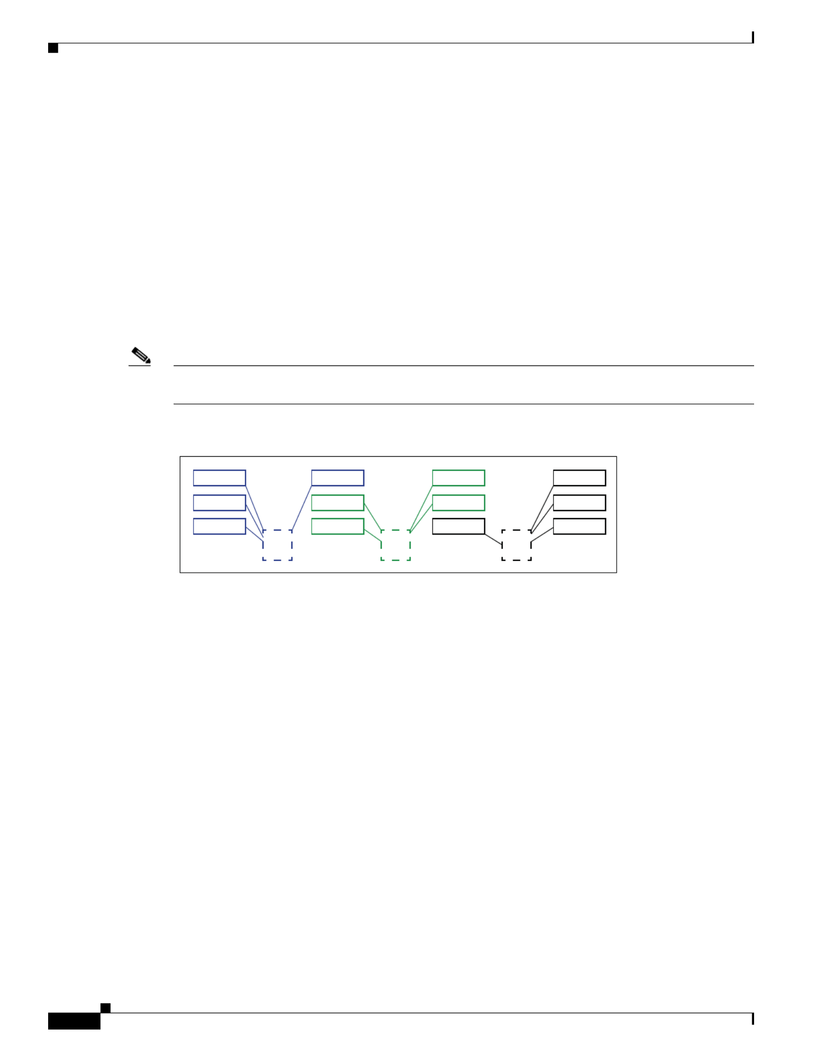
C-4
Cisco UCS C460 M4 Server Installation and Service Guide
OL-27640-01
Appendix C RAID Controller Considerations
RAID Controller Cabling
RAID Controller Cabling
This section contains the following topics:
•SAS Cable-to-Drive Bay Mapping, page C-4
•Cabling an 8-Port RAID Controller, page C-5
•Cabling a 12-Port RAID Controller, page C-6
SAS Cable-to-Drive Bay Mapping
The server chassis comes with three SAS cables pre-attached to the drive backplane SAS ports. It is
important to know which SAS cable ports on the drive backplane control the drive bays when attaching
SAS cables to your RAID controller card. See Figure C-1.
Note The view shown in the diagram in Figure C-1 is facing the front of the server. The SAS ports on the drive
backplane are shown in their physical position on the reverse (interior) side of the backplane.
Figure C-1 SAS Cable to Drive Bay Mapping (Facing the Front of the Server)
HDD 01
352325
HDD 05
HDD 09
S3
J35
HDD 02
HDD 06
HDD 10
S2
J36
HDD 03
HDD 07
HDD 11
S1
J37
HDD 04
HDD 08
HDD 12

C-5
Cisco UCS C460 M4 Server Installation and Service Guide
OL-27640-01
Appendix C RAID Controller Considerations
RAID Controller Cabling
Cabling an 8-Port RAID Controller
An 8-port RAID controller can control 8 drives.
Note When using an 8-port RAID controller, you must populate the eight drives that you want to control in
drive bays (3, 6, 7, 10) and (4, 8, 11, 12). That is, you must populate the bays that are controlled by SAS
backplane ports S1 and S2 as shown in Figure C-1.
The connectors on the card might not be labeled. See Figure C-2 for the card connector numbering.
Step 1 Attach the S1 SAS cable from drive backplane port J37 to the S1 port on the RAID controller card.
Step 2 Attach the S2 SAS cable from drive backplane port J36 to the S2 port on the RAID controller card.
Figure C-2 Cabling 8-Port RAID Controller Cards
S2
S1
S2
S1
S2
S1
S2
S1
UCS-RAID9361CV-8I
(SAS 0361-8i)
UCSC-MRAID12G
305102

C-6
Cisco UCS C460 M4 Server Installation and Service Guide
OL-27640-01
Appendix C RAID Controller Considerations
RAID Controller Cabling
Cabling a 12-Port RAID Controller
A 12-port RAID controller can control 12 drives.
The connectors on the card might not be labeled. See Figure C-3 for the card connector numbering.
Step 1 Attach the S1 SAS cable from drive backplane port J37 to the S1 port on the RAID controller card.
Step 2 Attach the S2 SAS cable from drive backplane port J36 to the S2 port on the RAID controller card.
Step 3 Attach the S3 SAS cable from drive backplane port J35 to the S3 port on the RAID controller card
Figure C-3 Cabling a 12-Port RAID Controller Card
S1
S2
S1
S2
S3 S3
UCSC-MRAIDC460
305103

C-7
Cisco UCS C460 M4 Server Installation and Service Guide
OL-27640-01
Appendix C RAID Controller Considerations
Restoring RAID Configuration After Replacing a RAID Controller
Restoring RAID Configuration After Replacing a RAID Controller
When you replace a RAID controller, the RAID configuration that is stored in the controller is lost.
Step 1 Replace your RAID controller. See Special Considerations for Cisco UCS Virtual Interface Cards,
page 3-48.
Step 2 If this was a full chassis swap, replace all drives into the drive bays, in the same order that they were
installed in the old chassis.
Step 3 Reboot the server and watch for the prompt to press F.
Step 4 Press F when you see the following onscreen prompt:
Foreign configuration(s) found on adapter.
Press any key to continue or ‘C’ load the configuration utility,
or ‘F’ to import foreign configuration(s) and continue.
Step 5 Press any key (other than C) to continue when you see the following onscreen prompt:
All of the disks from your previous configuration are gone. If this is
an unexpected message, then please power of your system and check your cables
to ensure all disks are present.
Press any key to continue, or ‘C’ to load the configuration utility.
Step 6 Watch the subsequent windows for confirmation that your RAID configuration was imported correctly:
•If you see the following message, your configuration was successfully imported. The LSI virtual
drive is also listed among the storage devices.
N Virtual Drive(s) found on host adapter.
•If you see the following message, your configuration was not imported. This problem can occur if
you do not press F quickly enough when prompted. In this case, reboot the server and try the import
operation again when you are prompted to press F.
0 Virtual Drive(s) found on host adapter.
For More Information
The LSI utilities have help documentation for more information about using the utilities.
For basic information about RAID and for using the utilities for the RAID controller cards, see the
Cisco UCS Servers RAID Guide.
Full LSI documentation is also available:
LSI MegaRAID SAS Software User’s Guide (for LSI MegaRAID)
http://www.lsi.com/DistributionSystem/AssetDocument/80-00156-01_RevH_SAS_SW_UG.pdf

C-8
Cisco UCS C460 M4 Server Installation and Service Guide
OL-27640-01
Appendix C RAID Controller Considerations
For More Information

D-1
Cisco UCS C240 M4 Server Installation and Service Guide
OL-32474-01
A P P E N D I X
D
GPU Card Installation
This appendix contains the following topics:
•Overview of Server Firmware Requirements, page D-1
•NVIDIA GPU Slot Population Rules, page D-2
•Requirement For All Supported GPUs: Memory-Mapped I/O Greater than 4 GB, page D-2
•Installing a GPU Card, page D-3
•NVIDIA Tesla M60 GPU GRID Software and Licensing, page D-5
•Installing Drivers to Support the NVIDIA GPU Cards, page D-15
Overview of Server Firmware Requirements
Table D-1 lists the minimum server firmware versions for the supported GPU cards.
Table D-1 Server Firmware Minimum Versions
GPU Cisco IMC/BIOS Minimum Version
NVIDIA GRID K1 1.5(6)
NVIDIA GRID K2 1.5(6)
NVIDIA Tesla K10 1.5(7)
NVIDIA Tesla K20 1.5(7)
NVIDIA Tesla K20X 1.5(7)
NVIDIA Tesla K40 1.5(7)
NVIDIA Tesla K80 2.0(6)
NVIDIA Tesla M60 2.0(9)

D-2
Cisco UCS C240 M4 Server Installation and Service Guide
OL-32474-01
Appendix D GPU Card Installation
NVIDIA GPU Slot Population Rules
•The GPU cards are double-wide and cover two slots. A GPU cards in slot 2 also covers slot 1. A GPU
card in slot 7 also covers slot 6.
•NVIDIA GPUs can support only less-than 1 TB of memory in the server. Therefore, do not install
1 TB or more total memory when using an NVIDIA GPU card in this server.
•Table D-2 shows the rules for populating NVIDIA GPU cards in the server.
Requirement For All Supported GPUs: Memory-Mapped I/O Greater than 4 GB
All supported GPU cards require enablement of the BIOS setting that allows greater than 4 GB of
memory-mapped I/O (MMIO).
Standalone Server
If the server is used in standalone mode, this BIOS setting is enabled by default:
Advanced > PCI Configuration > Memory Mapped I/O Above 4 GB [Enabled]
If you need to change this from a different setting, enter the BIOS Setup Utility by pressing F2 when
prompted during bootup.
Cisco UCS Manager Controlled Server
If the server is integrated with Cisco UCS Manager and controlled by a service profile, this setting is not
enabled by default in the service profile. You must enable it with a BIOS policy in your service profile.
Step 1 Refer to the Cisco UCS Manager configuration guide (GUI or CLI) for your release for instructions on
configuring service profiles:
Cisco UCS Manager Configuration Guides
Step 2 Refer to the chapter on Configuring Server-Related Policies > Configuring BIOS Settings.
Step 3 In the section of your profile for PCI Configuration BIOS Settings, set Memory Mapped IO Above 4GB
Config to one of the following:
•Enabled—Maps I/O of 64-bit PCI devices to 64 GB or greater address space.
•Platform Default—The policy uses the value for this attribute contained in the BIOS defaults for the
server. Use this only if you know that the server BIOS is set to use the Enabled default setting.
Step 4 Reboot the server.
Note Cisco UCS Manager pushes BIOS configuration changes through a BIOS policy or default BIOS
settings to the Cisco Integrated Management Controller (Cisco IMC) buffer. These changes
remain in the buffer and do not take effect until the server is rebooted.
Table D-2 NVIDIA GPU Population Rules
Single GPU Dual GPU Mix Two Different GPUs
PCIE 2
or
PCIE 71
1. If you have a GPU card in slot 7, you cannot also have a Qlogic QLE2562 HBA card in slot 9.
PCIE 2
and
PCIE 7
Not supported at this time
D-3
Cisco UCS C240 M4 Server Installation and Service Guide
OL-32474-01
Appendix D GPU Card Installation
Installing a GPU Card
Note For NVIDIA K80 and M60 GPU: When installed in the Cisco UCS C460 M4 server, the K80 and M60
GPUs use a different cable than the other GPU cards. You must order this cable when you order the K80
or M60 GPU (Cisco PID UCSC-300W-460M4).
Step 1 Remove a GPU card (or a blank filler panel) from the PCIe riser assembly:
a. Shut down and power off the server as described in Shutting Down and Powering Off the Server,
page 3-8.
b. Slide the server out the front of the rack far enough so that you can remove the top cover.
Caution If you cannot safely view and access the component, remove the server from the rack.
c. Remove the top cover as described in Removing or Replacing the Server Top Cover, page 3-10.
d. Lift the blue plastic retaining latch at the top of the PCIe riser until the latch is vertical (see
Figure 3-19). The lever action disengages the riser’s connector from the motherboard socket.
e. Lift straight up on both ends of the PCIe riser and remove it from the server. Set the riser on an
antistatic surface.
f. Open the hinged blue plastic card cover (see Figure 3-21).
g. Open the hinged card-tab retainer (see Figure 3-21). Pinch the two blue finger-grips toward the center
and swing open the retainer.
h. Pull evenly on both corners of the GPU card to remove it from the socket on the PCIe riser.
i. Disconnect the GPU card’s power cable from the PCIe riser power connector.
Step 2 Install a GPU card:
a. Connect the white connector of the included power cable to the white power-connector on the riser.
The power connector is adjacent to PCIE 2 on riser 1 or PCIE 6 on riser 2 (see Figure 3-21).
Caution Do not reverse the GPU power cable. Connect the black connector on the cable to the black connector on
the GPU card. Connect the white white connector on the cable to the connector on the PCIe riser. Never
connect a 6-pin cable connector to an 8-slot receptacle.
Note Your GPU card might be shipped with two power cables: a straight cable and a Y-cable. The straight cable
is used for connecting power to the GPU card in this server; do not use the Y-cable, which is used for
connecting the GPU card in external devices only.
Caution For NVIDIA K80 or M60: When installed in a Cisco UCS C460 M4 server, the NVIDIA K80 or M60
GPU must use a different power cable than other GPUs (UCSC-300W-460M4). You must plug the black
8-pin connector into the black connector on the GPU card and plug the white 10-pin connector into the
white power connector on the PCIe riser.
Produktspezifikationen
| Marke: | Cisco |
| Kategorie: | Server |
| Modell: | UCS C460 M4 |
Brauchst du Hilfe?
Wenn Sie Hilfe mit Cisco UCS C460 M4 benötigen, stellen Sie unten eine Frage und andere Benutzer werden Ihnen antworten
Bedienungsanleitung Server Cisco

15 August 2024
2 August 2024
30 Juli 2024
27 Juli 2024
25 Juli 2024
25 Juli 2024
25 Juli 2024
22 Juli 2024
14 Juli 2024
10 Juli 2024
Bedienungsanleitung Server
- Server Acer
- Server Asus
- Server Gigabyte
- Server HP
- Server Medion
- Server Sony
- Server ZyXEL
- Server Buffalo
- Server Allnet
- Server Linksys
- Server Netgear
- Server Fantec
- Server Technics
- Server Abus
- Server Megasat
- Server Toshiba
- Server Lindy
- Server Dell
- Server Lenovo
- Server Tripp Lite
- Server TRENDnet
- Server Western Digital
- Server AVerMedia
- Server Veritas
- Server Black Box
- Server Supermicro
- Server SilverStone
- Server NEC
- Server Monacor
- Server Seagate
- Server Fujitsu
- Server Maxdata
- Server Revox
- Server Totolink
- Server Conceptronic
- Server D-Link
- Server QNAP
- Server Digitus
- Server LevelOne
- Server APC
- Server Freecom
- Server Synology
- Server Kramer
- Server Intellinet
- Server Eaton
- Server Hikvision
- Server FLIR
- Server ELAC
- Server Planet
- Server Asustor
- Server Blackmagic Design
- Server Dane Elec
- Server Digi
- Server Dual Bay
- Server EMC
- Server GeoVision
- Server Ibm
- Server In Win
- Server Iomega
- Server LaCie
- Server Provision ISR
- Server Quantum
- Server Sun
- Server AMX
- Server ACTi
- Server Vimar
- Server Siig
- Server Intel
- Server Moxa
- Server StarTech.com
- Server Smart-AVI
- Server Mobotix
- Server Sonnet
- Server SEH
- Server Gefen
- Server Avocent
- Server Atlantis Land
- Server Hanwha
- Server ATen
- Server KanexPro
- Server Axis
- Server Advantech
- Server HGST
- Server Kiloview
- Server B&B Electronics
- Server Extron
- Server Atlona
- Server Rocstor
- Server Raidsonic
- Server G-Technology
- Server Infortrend
- Server Areca
- Server Silex
- Server Promise Technology
- Server Matrox
- Server Origin Storage
- Server Ernitec
- Server EXSYS
- Server Raritan
- Server C2G
- Server Chenbro Micom
- Server Lantronix
- Server IStarUSA
- Server Valcom
- Server TAIDEN
- Server MvixUSA
- Server Opengear
- Server Mr. Signal
- Server NETSCOUT
Neueste Bedienungsanleitung für -Kategorien-

24 November 2024

13 Oktober 2024
12 Oktober 2024
12 Oktober 2024

11 Oktober 2024
11 Oktober 2024

10 Oktober 2024
6 Oktober 2024

4 Oktober 2024
3 Oktober 2024