Cisco ASR-920-12SZ-IM Bedienungsanleitung
Lesen Sie kostenlos die 📖 deutsche Bedienungsanleitung für Cisco ASR-920-12SZ-IM (130 Seiten) in der Kategorie Router. Dieser Bedienungsanleitung war für 37 Personen hilfreich und wurde von 2 Benutzern mit durchschnittlich 4.5 Sternen bewertet
Seite 1/130

Cisco ASR-920-12SZ-IM and ASR-920-U-12SZ-IM Aggregation Services
Router Hardware Installation Guide
First Published: 2016-07-04
Last Modified: 2019-04-15
Americas Headquarters
Cisco Systems, Inc.
170 West Tasman Drive
San Jose, CA 95134-1706
USA
http://www.cisco.com
Tel: 408 526-4000
800 553-NETS (6387)
Fax: 408 527-0883

©2016 - 2019 Cisco Systems, Inc. All rights reserved.

C O N T E N T S
Overview 1
C H A P T E R 1
Cisco ASR 920 Router Features 1
GigabitEthernet Copper Ports 2
GE SFP Ports 2
SFP+ Ports 2
External Interfaces 7
Network Interfaces 7
Network Timing Interfaces 7
External Alarm Inputs 8
Management Interfaces 8
Management ENET Port 8
RS232 Console Port 8
USB Console 8
USB Mass Storage 9
Zero Touch Provisioning Button 9
RS232 Auxiliary Console Port 9
Power Supply 9
Redundancy 10
LED Indicators 10
PWR and STAT LEDs 11
CPU Management Port LEDs 12
SFP LEDs 12
SFP+ LEDs 12
RJ-45 LEDs 13
G.703/FXS/FXO Interface Module LEDs 13
Power Supply Unit LEDs 14
Cisco ASR-920-12SZ-IM and ASR-920-U-12SZ-IM Aggregation Services Router Hardware Installation Guide
iii

System–Interface LED Behavior 14
Fan Tray LEDs 15
Online Insertion and Removal 15
Licensing 16
Preparing for Installation 17
C H A P T E R 2
Safety Guidelines 17
Safety Warning Statements 18
Safety Guidelines for Personal Safety and Equipment Protection 18
Safety Precautions for Module Installation and Removal 18
Safety with Electricity 19
Power Supply Considerations 19
Preventing ESD Damage 20
Site Planning 20
General Precautions 20
Site Planning Checklist 21
Site Selection Guidelines 21
Environmental Requirements 21
Physical Characteristics 22
Air Flow Guidelines 22
Air Flow Guidelines for ETSI Rack Installation 23
Floor Loading Considerations 24
Site Power Guidelines 24
Electrical Circuit Requirements 25
Site Cabling Guidelines 25
Asynchronous Terminal Connections 25
Interference Considerations 25
Electromagnetic Interference 26
Radio Frequency Interference 26
Lightning and AC Power Fault Interference 26
Rack-Mounting Guidelines 26
Precautions for Rack-Mounting 26
Rack Selection Guidelines 27
Equipment Rack Guidelines 27
Cisco ASR-920-12SZ-IM and ASR-920-U-12SZ-IM Aggregation Services Router Hardware Installation Guide
iv
Contents

Installation Checklist 28
Creating a Site Log 29
Chassis-Lifting Guidelines 29
Tools and Equipment 30
Unpacking and Verifying the Shipped Contents 30
Installing the Cisco ASR 920 Series Router 33
C H A P T E R 3
Prerequisites 33
Installing the Router in a Rack 34
Attaching Brackets to the Router 34
Attaching Brackets for 19-Inch Racks 35
Attaching Brackets for 23-Inch Racks 37
Attaching Brackets for ETSI Racks 38
Mounting the Router in a Rack 39
Installing the Router Chassis in the Rack 39
Attaching the Cable Guides 40
Wall Mounting the Router 42
Attaching the Brackets to the Router for Wall-Mounting 42
Mounting Router on the Wall 43
Installing and Removing SFP Modules 45
Installing SFP Modules 45
Removing SFP Modules 46
Connecting to the Copper Ports 47
Connecting to SFP Modules 48
Connecting to Fiber-Optic SFP Modules 48
Installing the Chassis Ground Connection 49
Installing and Removing the Fan Tray 51
Installing the Fan Tray 51
Removing the Fan Tray 52
Interface Module Installation 53
Installing an Interface Module 54
Removing an Interface Module 54
Installing Patch Panel 54
Install 3G Patch Panel 59
Cisco ASR-920-12SZ-IM and ASR-920-U-12SZ-IM Aggregation Services Router Hardware Installation Guide
v
Contents

Install Rack Brackets 60
Set up 3G Patch Panel on Rack 67
Wall Mount 3G Patch Panel 79
Patch Panel Dimensions 81
Patch Panel Pinout 86
Panel and Bracket 87
Installing the Power Supply 87
Power Connection Guidelines 88
Guidelines for DC-Powered Systems 88
Guidelines for AC-Powered Systems 89
Preventing Power Loss 89
Installing the DC Power Supply Module 89
Activate a DC Power Supply Module 90
Install the DC Power Cables 91
Removing the DC Power Supply Module 93
Installing the AC Power Supply Module 94
Install the AC Power Cables 95
Activate an AC Power Supply Module 96
Removing the AC Power Supply Module 97
Powering On the Router 98
Connecting the Router to the Network 98
Connecting Console Cables 99
Connecting to the USB Serial Port Using Microsoft Windows 99
Connecting to the Console Port Using Mac OS X 99
Connecting to the Console Port Using Linux 100
Installing the Cisco USB Device Driver 100
Uninstalling the Cisco USB Driver 101
Connecting to the EIA Console Port 102
Connecting a Management Ethernet Cable 103
Installing and Removing SFP and SFP+ Modules 104
Connecting a USB Flash Device 104
Removing a USB Flash Device 104
Connecting Timing Cables 105
Connecting Cables to a GPS Interface 105
Cisco ASR-920-12SZ-IM and ASR-920-U-12SZ-IM Aggregation Services Router Hardware Installation Guide
vi
Contents

Connecting Ethernet Cables 107
Connecting Cables to SFP Modules 107
Connector and Cable Specifications 107
Initial Conguration 109
C H A P T E R 4
Checking Conditions Prior to System Startup 109
Powering Up the Router 109
Verifying the Front Panel LEDs 110
Verifying the Hardware Configuration 110
Checking Hardware and Software Compatibility 110
Configuring the Router at Startup 111
Accessing the CLI Using the Console 111
Configuring Global Parameters 112
Checking the Running Configuration Settings 112
Saving the Running Configuration to NVRAM 113
Safely Powering Off the Router 113
Troubleshooting 115
C H A P T E R 5
Pinouts 115
GPS Port Pinouts 115
Time-of-Day Port Pinouts 115
Alarm Port Pinouts 116
Management GigabitEthernet Port Pinouts 117
USB Console Port Pinouts 117
USB Flash or MEM Port Pinouts 118
Optical Fiber Specifications 118
Alarm Conditions 118
G.703/FXS/FXO Interface Module Pinout 119
LED Summary 120
Power Supply LEDs 120
Fan Tray LEDs 120
Site Log 121
C H A P T E R 6
Cisco ASR-920-12SZ-IM and ASR-920-U-12SZ-IM Aggregation Services Router Hardware Installation Guide
vii
Contents

Cisco ASR-920-12SZ-IM and ASR-920-U-12SZ-IM Aggregation Services Router Hardware Installation Guide
viii
Contents

C H A P T E R 1
Overview
The Cisco ASR-920-12SZ-IM and Cisco ASR-920U-12SZ-IM are collectively referred to as the Cisco
ASR-920-12SZ-IM Router in this document. Any differences between the routers are specifically called out.
Note
The Cisco ASR 920 Series Aggregation Services Router is a family of fixed configuration routers that provides
common network architecture to the Service Providers for macro and small cell networks.
This router acts as an access device for mobile backhaul services—macro Cell Site Router (CSR) and Small
Cell Router (SCR). As an access device, it provides capabilities like 1GE/10GE, MPLS, H-QoS, Services,
GPS clocking, PoE and fit within ETSI 300 mm depth cabinet. It can easily be integrated into the Unified
MPLS for Mobile Transport (UMMT) and Fixed Mobile Convergence (FMC) solution.
•Cisco ASR 920 Router Features, on page 1
•GigabitEthernet Copper Ports, on page 2
•GE SFP Ports, on page 2
•SFP+ Ports, on page 2
•External Interfaces, on page 7
Cisco ASR 920 Router Features
The router provides 1GE/10GE, MPLS, H-QoS, high availability hardware design, advanced Ethernet
Operations, Administration, and Maintenance (OAM), as well as advanced timing support, including satellite
timing (GNSS) based clocking, and PoE in one platform.
• ASR-920-12SZ-IM—This router has fixed Ethernet interfaces (8x1G copper + 4x1G SFP + 4x10G/1G
(dual rate)
• ASR-920-12SZ-IM-CC—Has the same specifications as the above variant. However, this chassis is
coated with an acrylic-based material to help improve the reliability against air-borne contamination.
The following table provides snapshot of the number and type of supported ports:
Type of 1 GE PortDual Rate 1G/10G Port1 GE PortASR 920 Sub-family
8 Cu ports Ge0/0/0 – Ge0/0/7
4 SFP ports Ge0/0/8 – Ge0/0/11
41
Te0/0/12 – Te 0/0/15
12ASR-920-12SZ-IM,
ASR-920-12SZ-IM-CC
Cisco ASR-920-12SZ-IM and ASR-920-U-12SZ-IM Aggregation Services Router Hardware Installation Guide
1

1Each port can operate at either 1G or 10G, and operates in a mutually exclusive way. You cannot insert
both 1G and 10G together. If you insert IG IMs (A900-IMA8T1Z, A900-IMA8S1Z, A900-IMA8T,
A900-IMA8S), the dual rate port would support only 10G.
GigabitEthernet Copper Ports
Fixed copper GigabitEthernet (GE) interfaces are provided through standard RJ-45 connectors. These ports
support the following features:
• Standard 100/1000Base-T/TX operation with forced or auto-negotiation for speed and duplex.
• Automatic crossover (auto-MDIX) for straight-through and crossover connections.
• Pause flow control as defined by the 802.3x standard.
• Frame size of 9216 bytes.
• Synchronous ENET operation that provides its recovered receive clock as an input clock source for the
SETS as well as uses the system-wide reference clock to derive its transmit clock.
GE SFP Ports
The GE SFP ports support the following features:
• 100Base-FX and 1000Base-X SFP modules.
• Digital optical monitoring as specified by the SFP.
• Any mix of SFPs is supported unless specifically noted.
• Pause flow control as defined by the 802.3x standard.
• Frame size of 9216 bytes.
• Synchronous ENET operation that provides its recovered receive clock as an input clock source for the
SETS as well as uses the system-wide reference clock to derive its transmit clock.
Copper based SFPs do not support synchronous ENET operations.
Note
SFP+ Ports
The SFP+ ports support the following features:
• Digital optical monitoring as specified by the optical transceiver module.
• Any mix of SFPs is supported unless specifically noted.
• Pause flow control as defined by the 802.3x standard.
• Frame size of 9216 bytes.
The following figures show the port numbering for the Cisco ASR 920 router:
Cisco ASR-920-12SZ-IM and ASR-920-U-12SZ-IM Aggregation Services Router Hardware Installation Guide
2
Overview
GigabitEthernet Copper Ports
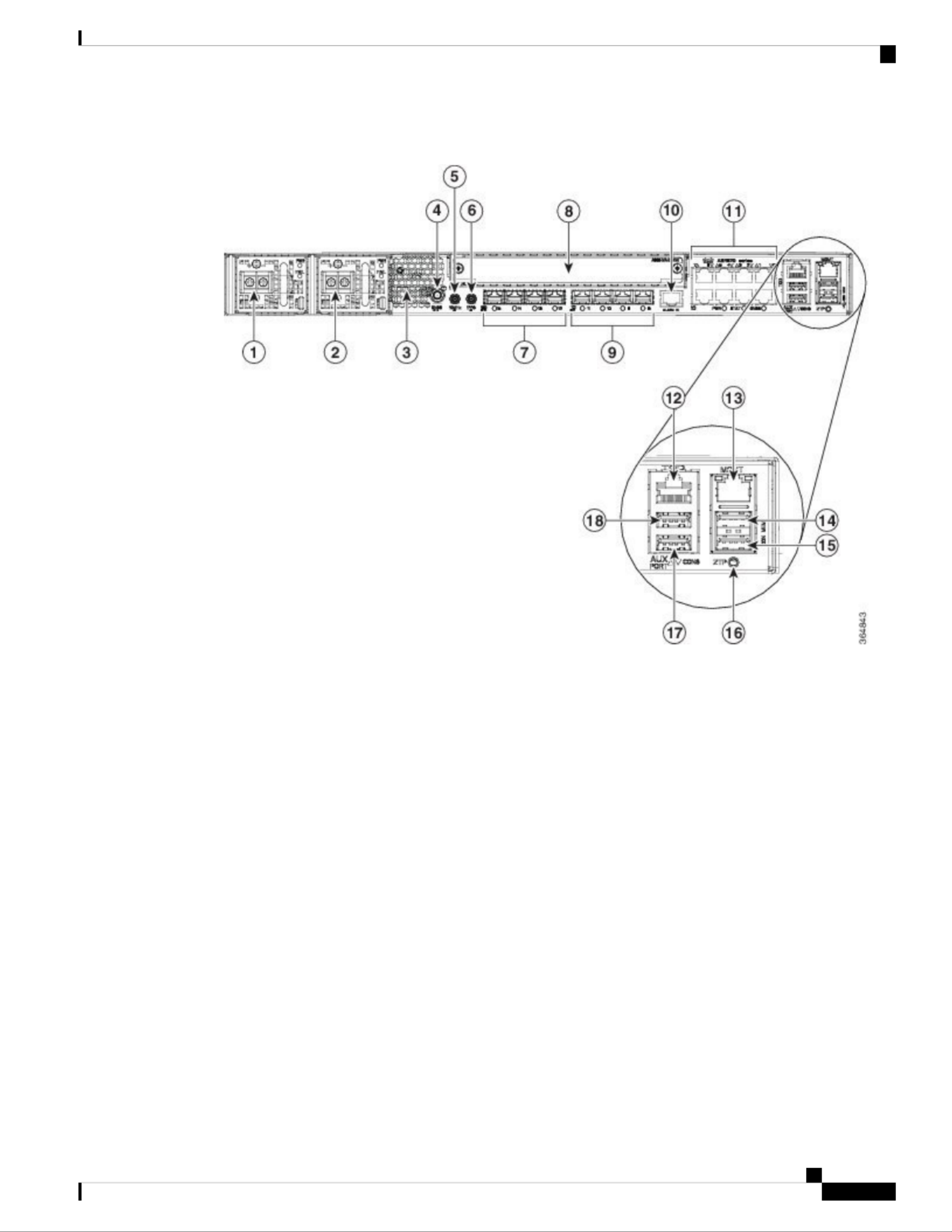
Figure 1: Front Panel of Cisco ASR-920-12SZ-IM Router With DC Power Supply—
Cisco ASR-920-12SZ-IM and ASR-920-U-12SZ-IM Aggregation Services Router Hardware Installation Guide
3
Overview
SFP+ Ports

Figure 2: Front Panel of Cisco ASR-920-12SZ-IM Router With AC Power Supply—
Alarm port10Power Supply 0 (AC or DC)1
Eight Copper port (1G PoE)
Port 0 is located at the bottom right, port 1 is
located at the top right, and so on.
Note
11Power Supply 1 (AC or DC)2
ToD port12Front Air-Inlet Area3
Management Port13GNSS RF IN (SMA threaded connector)4
USB Memory port14DIN 1.0/2.3 Snap-in connector (10MHZ)5
USB Console port15DIN 1.0/2.3 Snap-in connector (1PPS)6
Zero Touch Provisioning button16Four 1G/10G SFP+7
RS232 Console port17Interface Module8
RS232 Aux Console port18Four 1G SFP9
Cisco ASR-920-12SZ-IM and ASR-920-U-12SZ-IM Aggregation Services Router Hardware Installation Guide
4
Overview
SFP+ Ports

Figure 3: Rear View of Cisco ASR-920-12SZ-IM Router
Air vents3Fan tray1
—Grounding lug2
The following table describes the other features of Cisco ASR-920-12SZ-IM (AC and DC) Router.
Table 1: Cisco ASR-920-12SZ-IM Router Specifications
ASR-920-12SZ-IMSpecification
17.5 x 9.88 x 1.73 inchesDimensionWidth x Depth x Height
Total weight: 4.83 kg
Weight of PSU: 0.59 kg
Weight of Fan: 0.33 kg
Weight
One RURack Unit
Front to backAirflow
Front cable accessCable access
60 Gbps, 95 MppsSystem throughput
Power Supply
YesRedundant
YesAC
85V AC to 264V AC, nominal 100/240 VACVoltage Range
47 Hz to 63 Hz, nominal 50/60 HzFrequency Range
360 WMaximum Power
YesDC
-18 VDC to -32 VDC or -40 VDC to -72 VDCVoltage Range
-24 VDC/-48 VDC/-60 VDCNominal Voltage Range
375 WMaximum Power
–40º C to 70º COperating Temperature
Cisco ASR-920-12SZ-IM and ASR-920-U-12SZ-IM Aggregation Services Router Hardware Installation Guide
5
Overview
SFP+ Ports

ASR-920-12SZ-IMSpecification
• 4 alarm dry contact inputs (normally open)
• LED indicators for critical, major, and minor alarms
Alarms
For more information on these IM modules, see the Cisco ASR 903
Aggregation Series Router Hardware Installation Guide.
For more information on the supported IMs, see the Cisco ASR920 Data
sheet.
Supported Interface Modules
• Front or rear rail 19 or 23 inches
• ETSI 300 mm open cabinet
• Wall mount
Mounting option
12x1G and 4x10G/1G portsPort Configuration
4x10G SFP+ – Port [12:15]
4x1G SFP – Port [8:11]
8x1G PoE RJ45/Cu ports [0:7]
Port Numbering
Ports 12 to 15 are Dual Rate portsCombo Ports
Link/Activity/FaultCopper/1G/10G Port LEDs
Four temperature sensorsTemperature Sensors
External ports for 1PPS/TOD1PPS/ToD
Provides power over EthernetPoE
Connects to the external GPSGNSS
Cisco ASR-920-12SZ-IM and ASR-920-U-12SZ-IM Aggregation Services Router Hardware Installation Guide
6
Overview
SFP+ Ports
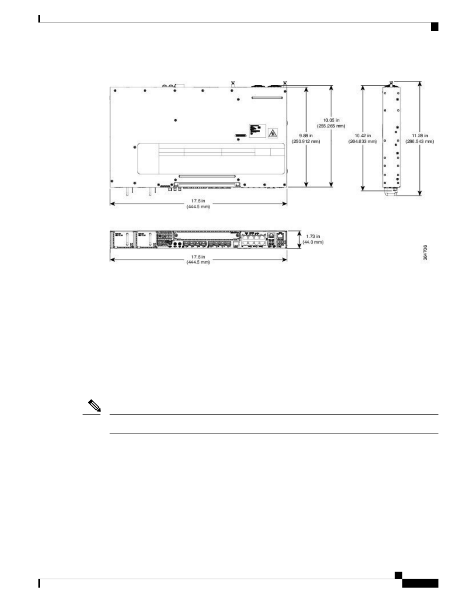
Figure 4: Cisco ASR-920-12SZ-IM Router Dimensions—
External Interfaces
The external physical interfaces on the front panel of the router are given below:
Network Interfaces
The network interfaces are provided through fixed ports.
• GE SFP ports—supports 100/1000 modes
• GE Copper RJ-45 ports—supports 10/100/1000 operation. All eight copper RJ-45 ports support
PoE/PoE+/UPoE with overall power budget of 180 W.
PoE is not supported when the system is powered with 24 V DC.
Note
• 10GE SFP+—supports 10G/1G mode depending on the SFP+/SFP in the network interface slot.
Network Timing Interfaces
• 10Mhz input or output—Miniature coaxial connectors for 10Mhz timing (input or output). You can use
this interfaces with an external GPS device to send or receive clocking from the router
• 1PPS input or output and ToD input or output—This interface is used for input or output of time-of-day
(ToD) and 1PPS pulses. ToD format includes both NTP and IEEE 1588-2008 time formats.
Cisco ASR-920-12SZ-IM and ASR-920-U-12SZ-IM Aggregation Services Router Hardware Installation Guide
7
Overview
External Interfaces
The same RS422 pins for 1PPS and TOD are shared between input and output directions. The direction for
each can be independently configured through software.
• GNSS RF IN—This interface is used to connect the external GPS antenna to the in-built GPS module.
External Alarm Inputs
The router supports four dry contact alarm inputs through an RJ-45 jack on the front panel.
• Normally Open—indicates that no current flows through the alarm circuit and the alarm is generated
when the current is flowing.
Each alarm input can be provisioned as critical, major, or minor.
Management Interfaces
The following management interfaces are supported:
Management ENET Port
A single management copper ENET port supporting 100/1000Base-T operation is provided on the front panel.
It uses a standard RJ-45 jack.
RS232 Console Port
The RS232 console port provides transmission (Tx), reception (Rx), and ground (Gnd).
The RS232 console port is enabled only through the Cisco-designed cable adapter USB type A cable to RJ-45
adapter cable. To use this port, disable the flow control on the terminal.
Note
Do not plug the USB-to-RJ45 adapter cable in the USB Memory port.
Caution
USB Console
A single USB 2.0 Type-A receptacle on the front panel of the router provides console access to ROMMON,
Cisco IOS-XE and diagnostics. While it uses the Type-A connector, it operates as a USB peripheral only for
connection to an external host computer. This interface requires the use of a Type-A to Type-A connector
instead of a standard USB cable.
Use of the USB console is mutually exclusive of the RS232 console port. This interface requires the use of a
Type-A to Type-A USB cable.
Note
Cisco ASR-920-12SZ-IM and ASR-920-U-12SZ-IM Aggregation Services Router Hardware Installation Guide
8
Overview
External Alarm Inputs

USB Mass Storage
A single USB 2.0 Type-A receptacle on the front panel of the router allows external USB mass storage devices,
such as standard USB flash drives. This interface is used to load images, load or store configurations, write
logs, and so on.
More than 8 GB is not supported in ROMMON mode,
Note
Zero Touch Provisioning Button
The Zero Touch Provisioning (ZTP) button on the front panel initiates the ZTP process on a short press of
less than eight seconds. Pressing the ZTP button for more than eight seconds causes a board reset.
RS232 Auxiliary Console Port
The RS232 Aux console port provides transmission (Tx), reception (Rx), and ground (Gnd).
The RS232 Aux console port is enabled only through the Cisco-designed cable adapter from USB type A
cable to RJ-45 adapter cable.
Note
This is a debug-only port. it is recommended that this port be used by field service engineers only.
Note
Power Supply
The router supports AC, DC, or a combination of both power supplies in a 1+1 redundant configuration. For
information on installing the power supplies, see the Installing the Power Supply section.
If only one PSU is present, a successful firmware upgrade to either primary or secondary microcontroller unit
(MCU) triggers a reload of device and is reloaded before any warning messages are displayed.
Note
Table 2: Power Supply Specification
DC (A920-PWR400-D)AC (A920-PWR400-A)Specification
18–32 VD or -40 to -72 VDC
Nominal - 24V VDC, or -48VDC, or -60VDC
85–264, nominal 100VAC, 240VAC
47–63 Hz, nominal 50/60 Hz
Input Voltage
375W (with PoE power of 180W)
150W Max (No PoE
375W (with PoE power of 180W)
150W Max (No PoE)
Maximum Input
Power
YesYesRedundant
Cisco ASR-920-12SZ-IM and ASR-920-U-12SZ-IM Aggregation Services Router Hardware Installation Guide
9
Overview
USB Mass Storage

DC (A920-PWR400-D)AC (A920-PWR400-A)Specification
YesYesHow Swap
YesYesCurrent sharing
Two-position terminal blockIEC60320, C15 style receptacleInput Connector
This product requires surge protection as part of the building installation. To comply with the Telcordia
GR-1089 NEBS standard for electromagnetic compatibility and safety, an external surge protective device
(SPD) is required at the AC power service equipment.
Note
For DC systems, if a surge of more than 500 V is expected, add an appropriate external surge protective device.
Note
The routers support AC and DC power supplies in a 1+1 redundant configuration.
One AC and one DC power supply in the same router is also a supported configuration.
Note
The router has a single fan-tray with four fans. The system is designed to operate at its maximum operating
temperature of 70º C, in case of failure of a single fan operating temperature of 65º C. The fan tray is
field-replaceable.
Redundancy
The router includes a slot for a redundant power supply. The redundant power supply option provides a second
power supply to ensure that power to the chassis continues uninterrupted if one power supply fails or input
power on one line fails. Redundancy is supported either with identical power supplies or a combination of
AC and DC power supply.
A redundant power supply on the router is recommended. Each power supply should be connected to separate
independent power sources to ensure that the router maintains power in the event of a power interruption
caused by an electrical failure, a wiring fault, or a tripped circuit breaker.
To comply with IEC 61850-3 (voltage interruptions), redundant power supplies with separately derived power
feeds are required.
Note
LED Indicators
This section describes the different types of LEDs and their behavior.
Cisco ASR-920-12SZ-IM and ASR-920-U-12SZ-IM Aggregation Services Router Hardware Installation Guide
10
Overview
Redundancy

PWR and STAT LEDs
The PWR LEDs are available on the front panel. These LEDs provide power on the board (PWR) status.
During power up state, these LEDs provide booting status and report errors.
The digital code signing functionality validates the integrity and authenticity of the ROMMON image before
booting it.
Note
Table 3: PWR and STAT LED Indications
CommentIndicationSTAT LED
state
PWR LED State
Permanent
Amber/Off indicates
FPGA configuration
failure.
Power in the system is all right and FPGA
configuration is taking place.
OffAmber
System is in
unresponsive state.
FPGA Image Validation Error.RedAmber
—Upgrade FPGA image error, continuing with
Golden FPGA image.
AmberFlashing Amber and
Green alternatively
—FPGA configuration successful and Digital
code signing successfully validated FPGA
image. Digital code signing passed the control
to Microloader to boot ROMMON.
OffFlashing Amber and
Green alternatively
—Digital code signing reported failure in
ROMMON image validation.
RedFlashing Amber and
Green alternatively
Both LEDs turn
Green once
provisioning is
complete.
ZTP process has begun.
A short press of the ZTP button
triggers the provisioning. A longer
press of more than eight seconds,
resets the board.
Note
Flashing
Amber
Flashing Amber
IOS-XE image is booting.OffGreen
—Successfully booted and system is operating
normally.
GreenGreen
—A minor alarm or synchronization is in
Holdover or free-running mode
AmberGreen
—A major or critical alarm (high temperature
reported for any sensor) or multiple fan
failure.
RedGreen
Cisco ASR-920-12SZ-IM and ASR-920-U-12SZ-IM Aggregation Services Router Hardware Installation Guide
11
Overview
PWR and STAT LEDs

CPU Management Port LEDs
The LED for the 100/1000 Management port is integrated on the connector itself. There are two LEDs in the
connector—the LED on the left indicates the Link/Activity status and the LED on the right indicates the
duplex status of the link.
Table 4: CPU Management Port LED Indication
IndicationLED StateLED
Link up in 1000 MbpsGreenLeft
Activity in 1000 MbpsBlinking Green
Link up in 100 MbpsAmber
Activity in 100 MbpsBlinking
Amber
Link downOff
Link up in full duplex
GreenRight
Link up in half duplexOff
SFP LEDs
Each SFP port has an LED indicator.
Table 5: SFP Port LED Indication
IndicationLED StateLED
Link up in 1000Base-X/100Base-FXGreenLabeled same as the SFP port number
Activity in 1000 Base-X/100Base-FXBlinking
Green
Fault/Error/Link downAmber
Administratively downOff
SFP+ LEDs
Each SFP+ port has an LED indicator.
Cisco ASR-920-12SZ-IM and ASR-920-U-12SZ-IM Aggregation Services Router Hardware Installation Guide
12
Overview
CPU Management Port LEDs
Table 6: SFP+ Port LED Indication
IndicationLED StateLED
Link up in 10G/1GGreenLabeled same as the SFP port number
Activity in 10G/1GBlinking
Green2
Fault/Error/Link downAmber
Administratively downOff
2For A900-IMA8T1Z, A900-IMA8S1Z, and A900-IMA2Z LED, status would be Green for Activity in
10G/1G.
RJ-45 LEDs
There is only one LED on each RJ45 port on the fixed slot (slot 0/0) and this indicates only the link or speed
status. There is no LED to show the Duplex state. However, there are two LEDs for IM RJ45 ports and they
indicate the Link and Duplex state.
Table 7: RJ-45 LED Indication
IndicationLED State
Link up in 10/100/1000Base-TGreen
Activity in 10/100/1000Base-TBlinking
Green
Fault/Error/Link downAmber
Administratively downOff
G.703/FXS/FXO Interface Module LEDs
The following table summarizes the LEDs for the G.703/FXS/FXO interface module.
Table 8: Cisco ASR 903 Router G.703/FXS/FXO IM LEDs
DescriptionColor or
State
LED Label
All power rails are within spec.GreenPower (PWR)
DisabledRed
No PowerOff
Cisco ASR-920-12SZ-IM and ASR-920-U-12SZ-IM Aggregation Services Router Hardware Installation Guide
13
Overview
RJ-45 LEDs

DescriptionColor or
State
LED Label
FailureRedOperating Status (STAT)
BootingYellow
OperationalGreen
No PowerOff
IM-FPGA Link/In-Frame, working properlyGreenPort Bi-color LEDs
Fault or Loop conditionSolid Yellow
Out of Service or not configured (default state)Off
Power Supply Unit LEDs
Each power supply unit has a corresponding LED on the front panel.
Table 9: PSU LED Indication
Power Supply ConditionFAIL LEDPower LED
Power Supply ON; valid input/outputOffGreen
PSU Warning due to OCP, OTP, UV, OV, OP, abnormal fan
operation
PSU continues to operate
Red 1Hz
blinking
Yellow 1Hz blinking
PSU failure due to OCP, OTP, UV, OV, OP, abnormal fan operation.
No valid output.
OnOff
Valid power present, shutdown by system.OffGreen 1Hz blinking
Input voltage lowOffYellow
No valid power input.OffOff
System Interface LED Behavior–
Table 10: 1G Copper and 1G SFP LED Indication
1G SFP Port LEDs1G Copper Port LEDs (Link)Event
OffOffROMMON
OffOffIOS Shut
AmberAmberIOS No shut (cable disconnect)
GreenGreenIOS No shut (Link Up)
Cisco ASR-920-12SZ-IM and ASR-920-U-12SZ-IM Aggregation Services Router Hardware Installation Guide
14
Overview
Power Supply Unit LEDs

Table 11: Dual Rate Port LED Indication
Dual Rate (1G/10G) Port LEDsEvent
OffROMMON
OffIOS Shut
AmberIOS No shut (cable disconnect)
GreenIOS No shut (Link Up)
Table 12: Management Port LED Indication
Management Port LEDs (Link/Duplex)Event
Green/OffROMMON
Off/OffIOS Shut
Amber/OffIOS No shut (cable disconnect)
Green/Green in 1G mode
Amber/Green in 100M mode
IOS No shut (cable connect)
Fan Tray LEDs
Table 13: Fan Tray LEDs
DescriptionColor/
State
System is not powered onOff
All fans are working normallyGreen
Single or multiple fan failures and critical errorAmber
ROMMONRed
Online Insertion and Removal
This router supports the following OIR operations:
• When an SFP is removed, there is no effect on traffic flowing on other ports.
• When an SFP is installed, the system initializes that port for operation based upon the current configuration.
If the inserted SFP is incompatible with the current configuration for that port, the port does not become
operational until the configuration is updated.
• Both power supplies are installed and active and the load may be shared between them or a single PSU
could support the whole load. When a power supply is not working or the input cable is removed, the
remaining power supply takes the entire load without disruption.
Cisco ASR-920-12SZ-IM and ASR-920-U-12SZ-IM Aggregation Services Router Hardware Installation Guide
15
Overview
Fan Tray LEDs

• When a fan tray is removed or replaced, there is no need to power down the router. However, when the
fan tray is removed from the router, the router shuts down automatically after some time, depending on
the ambient temperature. The time duration before the router shuts down is shown in the table below:
Licensing
The router supports the following types of licenses:
• Port Licensing—Port Upgrade license is available as a "Pay as you Grow" model.
• 6 ports 1GE upgrade license
• 2 ports 10G upgrade license
• Bulk License to enable 12x1port 1GE and 4x10GE ports
• Advanced Metro IP Access
• Metro IP Access
• Metro Access (default)
• Feature licensing
The following methods are used to activate the above licenses:
• Cisco Software Licensing—The Cisco Software License Activation feature is a set of processes and
components to activate Cisco software feature sets by obtaining and validating fee-based Cisco software
licenses.
Licenses generated by the Cisco Software Licensing are tied to the UDI of the chassis and a corresponding
watchtower device certificate (WDC) is stored in the system.
Note
• Cisco Smart Licensing—Smart Licensing is usage-based licensing where devices register with the Cisco
Secure server.
Cisco ASR-920-12SZ-IM and ASR-920-U-12SZ-IM Aggregation Services Router Hardware Installation Guide
16
Overview
Licensing

C H A P T E R 2
Preparing for Installation
This chapter describe how to prepare for the installation of the router at your site.
•Safety Guidelines, on page 17
•Safety Warning Statements, on page 18
•Safety Guidelines for Personal Safety and Equipment Protection, on page 18
•Safety Precautions for Module Installation and Removal, on page 18
•Safety with Electricity, on page 19
•Power Supply Considerations, on page 19
•Preventing ESD Damage, on page 20
•Site Planning, on page 20
•Air Flow Guidelines, on page 22
•Floor Loading Considerations, on page 24
•Site Power Guidelines, on page 24
•Electrical Circuit Requirements, on page 25
•Site Cabling Guidelines, on page 25
•Asynchronous Terminal Connections, on page 25
•Interference Considerations, on page 25
•Installation Checklist, on page 28
•Creating a Site Log, on page 29
•Chassis-Lifting Guidelines, on page 29
•Tools and Equipment, on page 30
•Unpacking and Verifying the Shipped Contents, on page 30
Safety Guidelines
Before you begin the installation, review the safety guidelines in this chapter to avoid injuring yourself or
damaging the equipment.
In addition, before replacing, configuring, or maintaining the router, review the safety warnings listed in the
Regulatory Compliance and Safety Information document.
Cisco ASR-920-12SZ-IM and ASR-920-U-12SZ-IM Aggregation Services Router Hardware Installation Guide
17

Safety Warning Statements
Before working on a system that has an on/off switch, turn OFF the power and unplug the power cord.
Statement 1
Warning
This unit might have more than one power supply connection. All connections must be removed to de-energize
the unit. Statement 1028
Warning
This equipment must be grounded. Never defeat the ground conductor or operate the equipment in the absence
of a suitably installed ground conductor. Contact the appropriate electrical inspection authority or an electrician
if you are uncertain that suitable grounding is available. Statement 1024
Warning
Before working on equipment that is connected to power lines, remove jewelry (including rings, necklaces,
and watches). Metal objects will heat up when connected to power and ground and can cause serious burns
or weld the metal object to the terminals. Statement 43
Warning
For other standard warning messages and their translations, see the Regulatory Compliance and Safety
Information for the Cisco ASR 920 Series Aggregation Services Router document.
SafetyGuidelines for Personal Safetyand Equipment Protection
The following guidelines help ensure your safety and protect the equipment. This list does not include all the
potentially hazardous situations. Therefore, you should be on alert.
• Before moving the system, always disconnect all the power cords and interface cables.
• Never assume that power is disconnected from a circuit; always check.
• Before and after installation, keep the chassis area clear and dust free.
• Keep tools and assembly components away from walk areas where you or others could trip over them.
• Do not work alone if potentially hazardous conditions exist.
• Do not perform any action that creates a potential hazard to people or makes the equipment unsafe.
• Do not wear loose clothing that may get caught in the chassis.
• When working under conditions that may be hazardous to your eyes, wear safety glasses.
Safety Precautions for Module Installation and Removal
To see the safety precautions for module installation and removal, see the Regulatory Compliance and Safety
Information for the Cisco ASR 920 Series Aggregation Services Router document.
Cisco ASR-920-12SZ-IM and ASR-920-U-12SZ-IM Aggregation Services Router Hardware Installation Guide
18
Preparing for Installation
Safety Warning Statements

Safety with Electricity
To see the safety with electricity, see the Regulatory Compliance and Safety Information for the Cisco ASR
920 Series Aggregation Services Router document.
When working on equipment powered by electricity, follow these guidelines:
• Locate the room’s emergency power-off switch. If an electrical accident occurs, you will be able to
quickly turn off the power.
• Before starting work on the system, turn off the DC main circuit breaker and disconnect the power
terminal block cable.
• Before doing the following, disconnect all power:
• Working on or near power supplies
• Installing or removing a router chassis or network processor module
• Performing most hardware upgrades
• Never install equipment that appears damaged.
• Carefully examine your work area for possible hazards, such as moist floors, ungrounded power extension
cables, and missing safety grounds.
• Never assume that power is disconnected from a circuit; always check.
• Never perform any action that creates a potential hazard to people or makes the equipment unsafe.
• If an electrical accident occurs, proceed as follows:
• Use caution, and do not become a victim yourself.
• Turn off power to the router.
• If possible, send another person to get medical aid. Otherwise, determine the condition of the victim,
and then call for help.
• Determine whether the person needs rescue breathing or external cardiac compressions; then take
appropriate action.
In addition, use the following guidelines when working with any equipment that is disconnected from a power
source, but still connected to telephone wiring or network cabling:
• Never install telephone wiring during a lightning storm.
• Never install telephone jacks in wet locations unless the jack is specifically designed for it.
• Never touch uninsulated telephone wires or terminals unless the telephone line is disconnected at the
network interface.
• When installing or modifying telephone lines, use caution.
Power Supply Considerations
Check the power at your site to ensure that you are receiving clean power (free of spikes and noise). Install a
power conditioner, if necessary.
Cisco ASR-920-12SZ-IM and ASR-920-U-12SZ-IM Aggregation Services Router Hardware Installation Guide
19
Preparing for Installation
Safety with Electricity

Preventing ESD Damage
This equipment needs to be grounded. Use a green and yellow 6 AWG ground wire to connect the host to
earth ground during normal use. Statement 383
Warning
Electrostatic discharge (ESD) can damage equipment and impair electrical circuitry. ESD may occur when
electronic printed circuit cards are improperly handled and can cause complete or intermittent failures. When
removing and replacing modules, always follow ESD prevention procedures:
• Ensure that the router chassis is electrically connected to earth ground.
• Wear an ESD-preventive wrist strap, ensuring that it makes good skin contact. To channel unwanted
ESD voltages safely to ground, connect the clip to an unpainted surface of the chassis frame. To guard
against ESD damage and shocks, the wrist strap and cord must operate effectively.
• If no wrist strap is available, ground yourself by touching a metal part of the chassis.
• When installing a component, use any available ejector levers or captive installation screws to properly
seat the bus connectors in the backplane or midplane. These devices prevent accidental removal, provide
proper grounding for the system, and help to ensure that bus connectors are properly seated.
• When removing a component, use available ejector levers or captive installation screws, if any, to release
the bus connectors from the backplane or midplane.
• Handle components by their handles or edges only; do not touch the printed circuit boards or connectors.
• Place a removed component board side up on an antistatic surface or in a static-shielding container. If
you plan to return the component to the factory, immediately place it in a static-shielding container.
• Avoid contact between the printed circuit boards and clothing. The wrist strap only protects components
from ESD voltages on the body; ESD voltages on clothing can still cause damage.
• Never attempt to remove the printed circuit board from the metal carrier.
For the safety of your equipment, periodically check the resistance value of the antistatic wrist strap. It should
be between 1 and 10 Mohm.
Note
Site Planning
The sections describe how to plan for the installation of the Cisco ASR 920 Series Router.
General Precautions
Observe the following general precautions when using and working with your router::
• Keep your system components away from radiators and heat sources and do not block cooling vents.
• Do not spill food or liquids on your system components and never operate the product in a wet
environment.
• Do not push any objects into the openings of your system components. Doing so can cause fire or electric
shock by shorting out interior components.
Cisco ASR-920-12SZ-IM and ASR-920-U-12SZ-IM Aggregation Services Router Hardware Installation Guide
20
Preparing for Installation
Preventing ESD Damage

• Position system cables and power supply cable carefully. Route system cables and the power supply
cable and plug so that they are not stepped on or tripped over. Be sure that nothing else rests on your
system component cables or power cable.
• Do not modify power cables or plugs. Consult a licensed electrician or your power company for site
modifications. Always follow your local and national wiring rules.
• If you turn off your system, wait at least 30 seconds before turning it on again to avoid damage of system
components.
Site Planning Checklist
Use the following checklist to perform and account for all the site planning tasks described in this chapter:
• The site meets the environmental requirements.
• The site’s air conditioning system can compensate for the heat dissipation.
• The floor space that the router occupies can support the weight of the system.
• Electrical service to the site complies with the requirements.
• The electrical circuit servicing the router complies with the requirements.
• Consideration has been given to the console port wiring and limitations of the cabling involved, according
to TIA/EIA-232F.
• The router's Ethernet cabling distances are within the prescribed limitations.
• The equipment rack in which you plan to install the router complies with prescribed requirements.
• When selecting the location of the rack, careful consideration must be given to safety, ease of maintenance,
and proper airflow.
Site Selection Guidelines
The router require specific environmental operating conditions. Temperature, humidity, altitude, and vibration
can affect the performance and reliability of the router. The following sections provide specific information
to help you plan for the proper operating environment.
The routers are designed to meet the industry EMC, safety, and environmental standards described in the
Regulatory Compliance and Safety Information for the Cisco ASR 920 Series Router document.
Environmental Requirements
Environmental monitoring of the Cisco ASR 920-24SZ-IM, ASR-920-24SZ-M, ASR-920-24TZ-M Router
protects the system and components from damage caused by excessive voltage and temperature conditions.
To ensure normal operation and avoid unnecessary maintenance, plan and prepare your site configuration
before installation. After installation, make sure that the site maintains the environmental characteristics
described in table.Cisco ASR-920-12SZ-IM Router Specications
For an outside plant installation (cell site cabinet, hut etc.), it is required that the router be protected against
airborne contaminants, dust, moisture, insects, pests, corrosive gases, polluted air or other reactive elements
present in the outside air. To achieve this level of protection, we recommend that the unit be installed in a
fully sealed enclosure or cabinet. Examples of such cabinets include IP65 cabinets with heat exchanger
complying with Telecordia GR487. Temperature must be maintained within –40º C to 70º C.
The equipment shall be placed inside a space protected from direct outside weather and environmental stresses
by an enclosure, and where the operating climate, as defined by Class 2 of GR-3108-CORE, is between
• -40°C (-40°F) and 70°C (158°F)
Cisco ASR-920-12SZ-IM and ASR-920-U-12SZ-IM Aggregation Services Router Hardware Installation Guide
21
Preparing for Installation
Site Planning Checklist

Note the following points:
• When installing the routerouter in a back-to-back position with another device, ensure that there is a
minimum of 10 cm air flow clearance between the two devices.
• If airflow through the equipment rack and the routers that occupy it is blocked or restricted, or if the
ambient air being drawn into the rack is too warm, an overtemperature condition may occur within the
rack and the routers that occupy it.
• The site should also be as dust-free as possible. Dust tends to clog the router fans, reducing the flow of
cooling air through the equipment rack and the routers that occupy it, thus increasing the risk of an
overtemperature condition.
• Enclosed racks must have adequate ventilation. Ensure that the rack is not congested because each router
generates heat. An enclosed rack should have louvered sides and a fan to provide cooling air. Heat that
is generated by the equipment near the bottom of the rack can be drawn upward into the intake ports of
the equipment above.
• When mounting a chassis in an open rack, ensure that the rack frame does not block the exhaust fans.
• When rack-installed equipment fails, especially equipment in an enclosed rack, try operating the equipment
by itself, if possible. Power off all the other equipment in the rack (and in adjacent racks) to give the
router maximum cooling air and clean power.
• Avoid installing the router in a location in which the chassis air intake vents may draw in the exhaust air
from adjacent equipment. Consider how the air flows through the router; the airflow direction is front to
back, with ambient air drawn in from the vents located on the sides of the chassis.
Air Flow Guidelines for ETSI Rack Installation
To install a Cisco ASR 920 Series Router in a 2-post or 4-post rack, the front and rear doors of the cabinet
must be removed. It is recommended that you maintain a minimum clearance distance as mentioned below,
at all times.
• front clearance—12.7 cm
Cisco ASR-920-12SZ-IM and ASR-920-U-12SZ-IM Aggregation Services Router Hardware Installation Guide
23
Preparing for Installation
Air Flow Guidelines for ETSI Rack Installation

• rear clearance—14 cm
If you are mounting the chassis in a 4-post enclosed cabinet, ensure that you have a minimum of 14 cm of
clearance on each side of the chassis.
Floor Loading Considerations
Ensure that the floor under the rack supporting the Cisco ASR 920 Series Routers is capable of supporting
the combined weight of the rack and all the other installed equipment.
To assess the weight of a fully configured Cisco ASR 920 Series Router, see the Cisco ASR-920-12SZ-IM
Router Specications table.
For additional information about floor loading requirements, see the GR-63-CORE, Network Equipment
Building System (NEBS) Requirements: Physical Protection document.
Site Power Guidelines
The router have specific power and electrical wiring requirements. Adhering to these requirements ensures
reliable operation of the system. Follow these precautions and recommendations when planning your site
power for the router:
• The redundant power option provides a second, identical power supply to ensure that power to the chassis
continues uninterrupted if one power supply fails or input power on one line fails.
• Connect each of the two power supplies to a separate input power source. If you fail to do this, your
system might be susceptible to total power failure due to a fault in the external wiring or a tripped circuit
breaker.
• To prevent a loss of input power, be sure that the total maximum load on each circuit supplying the power
supplies is within the current ratings of the wiring and the breakers.
• Check the power at your site before installation, and periodically after installation to ensure that you are
receiving clean power. Install a power conditioner, if necessary.
• Provide proper grounding to avoid personal injury and damage to the equipment due to lightning striking
power lines or due to power surges. The chassis ground must be attached to a central office or other
interior ground system.
This product requires short-circuit (overcurrent) protection to be provided as part of the building installation.
Install only in accordance with national and local wiring regulations.
Caution
The router installation must comply with all the applicable codes, and is approved for use with copper
conductors only. The ground bond-fastening hardware should be of compatible material and preclude loosening,
deterioration, and electrochemical corrosion of hardware and joined material. Attachment of the chassis ground
to a central office or other interior ground system must be made with a 6-AWG gauge wire copper ground
conductor at a minimum.
Note
For information on power specifications, see Power Supply Specication table.
Cisco ASR-920-12SZ-IM and ASR-920-U-12SZ-IM Aggregation Services Router Hardware Installation Guide
24
Preparing for Installation
Floor Loading Considerations

Electrical Circuit Requirements
Each router requires a dedicated electrical circuit. If you equip the router with dual-power feeds, provide a
separate circuit for each power supply to avoid compromising the power redundancy feature.
The ruters can be powered by a DC source or an AC source. Ensure that equipment grounding is present and
observe the power-strip ratings. Make sure that the total ampere rating of all the products plugged into the
power strip does not exceed 80% of the rating.
Site Cabling Guidelines
This section contains guidelines for wiring and cabling at your site. When preparing your site for network
connections to the router, consider the type of cable required for each component, and the cable limitations.
Consider the distance limitations for signaling, electromagnetic interference (EMI), and connector compatibility.
Possible cable types are fiber, thick or thin coaxial, foil twisted-pair, or unshielded twisted-pair cabling.
Also consider any additional interface equipment you need, such as transceivers, hubs, switches, modems,
channel service units (CSU), or data service units (DSU).
Before you install the router, have all the additional external equipment and cables on hand. For information
about ordering, contact a Cisco customer service representative.
The extent of your network and the distances between the network interface connections depend, in part, on
the following factors:
• Signal type
• Signal speed
• Transmission medium
The distance and rate limits referenced in the following sections are the IEEE-recommended maximum speeds
and distances for signaling purposes. Use this information as a guideline when planning your network
connections to installing the router.prior
If wires exceed the recommended distances, or if wires pass between buildings, give special consideration to
the effect of a lightning strike in your vicinity. The electromagnetic pulse caused by lightning or other
high-energy phenomena can easily couple enough energy into unshielded conductors to destroy electronic
devices. If you have had problems of this sort in the past, you may want to consult experts in electrical surge
suppression and shielding.
Asynchronous Terminal Connections
The router provides a console port to connect a terminal or computer for local console access. The port has
an RJ-45 connector and supports RS-232 asynchronous data with distance recommendations specified in the
IEEE RS-232 standard.
Interference Considerations
When wires are run for any significant distance, there is a risk that stray signals will be induced on the wires
as interference. If interference signals are strong, they may cause data errors or damage to the equipment.
Cisco ASR-920-12SZ-IM and ASR-920-U-12SZ-IM Aggregation Services Router Hardware Installation Guide
25
Preparing for Installation
Electrical Circuit Requirements

The sections describe the sources of interference and how to minimize their effects on the router.
Electromagnetic Interference
ll the equipment powered by AC current can propagate electrical energy that can cause EMI and possibly
affect the operation of other equipment. The typical sources of EMI are equipment power cords and power
service cables from electric utility companies.
Strong EMI can destroy the signal drivers and receivers in the router and even create an electrical hazard by
causing power surges through the power lines into installed equipment. These problems are rare, but could
be catastrophic.
To resolve these problems, you need specialized knowledge and equipment that could consume substantial
time and money. However, you can ensure that you have a properly grounded and shielded electrical
environment, paying special attention to the need for electrical surge suppression.
For information about the electrode magnetic compliance standards supported on the Cisco ASR 920 Series
Router, see the Regulatory Compliance and Safety Information for the Cisco ASR 920 Series Aggregation
Services Router document.
Radio Frequency Interference
When electromagnetic fields act over a long distance, radio frequency interference (RFI) may be propagated.
Building wiring can often act as an antenna, receiving the RFI signals and creating more EMI on the wiring.
If you use twisted-pair cable in your plant wiring with a good distribution of grounding conductors, the plant
wiring is unlikely to emit radio interference. If you exceed the recommended distances, use a high-quality
twisted-pair cable with one ground conductor for each data signal.
Lightning and AC Power Fault Interference
If signal wires exceed the recommended cabling distances, or if signal wires pass between buildings, you
should consider the effect that a lightning strike in your vicinity might have on the router.
The electromagnetic pulse (EMP) generated by lightning or other high-energy phenomena can couple enough
energy into unshielded conductors to damage or destroy electronic equipment. If you have previously
experienced such problems, you should consult with RFI and EMI experts to ensure that you have adequate
electrical surge suppression and shielding of signal cables in your Cisco ASR 920 Series Router operating
environment.
Rack-Mounting Guidelines
The sections provide guidelines for rack-mounting.
Precautions for Rack-Mounting
The following rack-mount guidelines are provided to ensure your safety:
• Ensure that the rack is level and stable before extending a component from the rack.
• Ensure that proper airflow is provided to the components in the rack.
• Do not step on or stand on any component or system when servicing other systems or components in a
rack.
Cisco ASR-920-12SZ-IM and ASR-920-U-12SZ-IM Aggregation Services Router Hardware Installation Guide
26
Preparing for Installation
Electromagnetic Interference

• When mounting the router in a partially filled rack, load the rack from the bottom to the top, with the
heaviest component at the bottom of the rack.
• If the rack is provided with stabilizing devices, install the stabilizers before mounting or servicing the
unit in the rack.
Rack Selection Guidelines
The router can be mounted in most two-post or four-post, 19-inch equipment racks that comply with the
Electronic Industries Association (EIA) standard for equipment racks (EIA-310-D 19-inch). The rack must
have at least two posts with mounting flanges to mount the chassis.
When mounting a chassis in any type of rack equipment, ensure that the inlet air to the chassis does not exceed
70° C.
Caution
The distance between the center lines of the mounting holes on the two mounting posts must be 18.31 inch ±
0.06 inch (46.50 cm ± 0.15 cm). The rack-mounting hardware included with the chassis is suitable for most
19-inch equipment racks.
Consider installing the router in a rack with the following features:
• NEBS-compliant, 19-inch wide (48.3-cm) rack.
• EIA or European Telecommunications Standards Institute (ETSI) hole patterns in the mounting rails.
The required mounting hardware is shipped with the router. If the rack that you plan to install the system
in has metric-threaded rails, you must provide your own metric-mounting hardware.
• Perforated top and open bottom for ventilation to prevent overheating.
• Leveling feet for stability.
The router is not recommended to be installed in an enclosed rack because the chassis requires an unobstructed
flow of cooling air to maintain acceptable operating temperatures for its internal components. If you use an
enclosed rack, ensure that the air flow requirements are maintained as discussed in .Air Flow Guidelines
Caution
Equipment Rack Guidelines
The placement of a rack can affect personnel safety, system maintenance, and the system’s ability to operate
within the environmental characteristics. Choose a proper location for the router by following the guidelines
described here.
Locating for Safety
If the Cisco ASR 920 Series Router is the heaviest or the only piece of equipment in the rack, consider installing
it at or near the bottom to ensure that the rack’s center of gravity is as low as possible.
For additional information about the proper placement of electronic equipment, consult the GR-63-CORE,
Network Equipment Building System (NEBS) Requirements: Physical Protection document.
Locating for Easy Maintenance
It is recommended that you maintain a minimum clearance distance as mentioned below, at all times.
• front clearance—12.7 cm
Cisco ASR-920-12SZ-IM and ASR-920-U-12SZ-IM Aggregation Services Router Hardware Installation Guide
27
Preparing for Installation
Rack Selection Guidelines

• rear clearance—10 cm
This space ensures that you can remove the router components and perform routine maintenance and upgrades
easily.
Avoid installing the router in a congested rack and consider how routing of cables from other pieces of
equipment in the same rack could affect access to the router cards.
The front and rear of the chassis must remain unobstructed to ensure adequate airflow and prevent overheating
inside the chassis.
To avoid problems during installation and ongoing operations, follow these general precautions when you
plan equipment locations and connections:
• Use the show environment all command regularly to check the internal system status. The environmental
monitor continually checks the interior chassis environment; it provides warnings about high temperature
and creates reports on other potentially dangerous occurrences. If warning messages are displayed, take
immediate action to identify the cause, and correct the problem.
• Keep the router off the floor and out of areas that collect dust.
• Follow ESD-prevention procedures to avoid damage to equipment. Damage from static discharge can
cause immediate or intermittent equipment failure.
Locating for Proper Airflow
Ensure that the router location has enough airflow to keep the system operating within the environmental
characteristics and the air temperature is sufficient to compensate for the heat dissipated by the system. For
more information, see the section.Air Flow Guidelines
Installation Checklist
To assist you with your installation and to provide a record of what was done by whom and when, photocopy
the Cisco ASR 920 Series Router Installation Checklist shown in the table below. Use this to record the
completion and verification of each procedure. After the checklist is completed, place it in your Site Log along
with the other records pertaining to your new Cisco router.
Table 14: Installation Checklist
DateVerified ByTask
Date on which chassis received
Chassis and all accessories
unpacked
Types and numbers of interfaces
verified
Safety recommendations and
guidelines reviewed
Installation Checklist copied
Site Log established and
background information entered
Cisco ASR-920-12SZ-IM and ASR-920-U-12SZ-IM Aggregation Services Router Hardware Installation Guide
28
Preparing for Installation
Locating for Proper Airflow

DateVerified ByTask
Site power voltages verified
Site environmental specifications
verified
Required passwords, IP addresses,
device names, and so on, available
Required tools available
Network connection equipment
available
Cable-management brackets
installed (optional, but
recommended)
AC power cables connected to AC
sources and router
DC power cables connected to DC
sources and router
Network interface cables and
devices connected
System power turned on
System boot complete (STATUS
LED is on)
Correct software configuration
displayed after system banner
appears
Creating a Site Log
The Site Log provides a record of all the actions related to installing and maintaining the router. Keep it in
an accessible place near the chassis so that anyone who performs tasks has access to it.
Create the Site Log prior to the installation. (See “Site Log” for more information about the Site Log as well
as a sample Site Log that can be used to make copies.)
Chassis-Lifting Guidelines
The chassis is not intended to be moved frequently. Before you install the system, ensure that your site is
properly prepared so that you can avoid having to move the chassis later to accommodate power sources and
network connections.
Cisco ASR-920-12SZ-IM and ASR-920-U-12SZ-IM Aggregation Services Router Hardware Installation Guide
29
Preparing for Installation
Creating a Site Log

Each time you lift the chassis or any heavy object, follow these guidelines:
• Ensure that your footing is solid, and balance the weight of the chassis between your feet.
• Lift the chassis slowly; never move suddenly or twist your body as you lift.
• Keep your back straight and lift with your legs, not your back. If you must bend down to lift the chassis,
bend at the knees, not at the waist, to reduce the strain on your back muscles.
• Do not remove installed components from the chassis.
• Always disconnect all external cables before lifting or moving the chassis.
To prevent personal injury or damage to the chassis, never attempt to lift or tilt the chassis using the handles
on modules (such as power supplies, fans, or cards); these types of handles are not designed to support the
weight of the unit. Lift the unit only by using handles that are an integral part of the chassis, or by grasping
the chassis underneath its lower edge. Statement 163
Warning
Tools and Equipment
You need the following tools and equipment to install and upgrade the router and its components:
• ESD-preventive cord and wrist strap
• Antistatic mat or antistatic foam
• Number 1 and Number 2 Phillips-head screwdrivers
• #12-24 pan-head screws to secure the router to the equipment rack
• Cables for connecting to the network ports (depending on the configuration)
For more information about cable specifications, see the Troubleshooting section.
Note
• Ethernet hub, switch, or PC with a network interface card for connecting to the Ethernet ports
• Console terminal (an ASCII terminal or a PC running terminal emulation software) that is configured
for 9600 baud, 8 data bits, no parity, no flow control, and 1stop bit
• Console cable for connecting to the console port
• Ratcheting torque screwdriver with a Phillips head that exerts up to 30-pound force per square inch (in-lb)
or 0.02-kilograms force per square millimeter (kgf/mm2) of pressure
• Crimping tool as specified by the ground lug manufacturer
• Wire-stripping tools for stripping both 6-AWG and 12-AWG wires
• Tape measure and level
Only trained and qualified personnel should be allowed to install or replace this equipment. Statement 49
Warning
Unpacking and Verifying the Shipped Contents
When you receive your chassis, perform the following steps:
Cisco ASR-920-12SZ-IM and ASR-920-U-12SZ-IM Aggregation Services Router Hardware Installation Guide
30
Preparing for Installation
Tools and Equipment

Procedure
Step 1 Inspect the box for any shipping damage. If there is obvious physical damage, contact your Cisco service
representative.
Step 2 Unpack the Cisco ASR 920-24SZ-IM, ASR-920-24SZ-M, ASR-920-24TZ-M Router.
Step 3 Perform a visual inspection of the chassis.
Step 4 Use the table below to check the contents of the Cisco ASR 920-24SZ-IM, ASR-920-24SZ-M,
ASR-920-24TZ-M Router shipping container. Do not discard the shipping container. You will need the
container if you move or ship the Cisco ASR 920-24SZ-IM, ASR-920-24SZ-M, ASR-920-24TZ-M Router
in the future.
Table 15: Cisco ASR 920-24SZ-IM, ASR-920-24SZ-M, ASR-920-24TZ-M Router Default Shipping Container Contents
DescriptionComponent
Cisco ASR 920 Series Router chassis
Fan tray (PID: ASR-920-FAN-TRAY). By default,
the fan tray is installed in the chassis.
Chassis (PID: ASR-920-12SZ-IM)
Chassis rack-mount brackets (19-inch EIA) with eight
screws
Accessories kit
Two cable guides with two screws
One earth lug with two 10-32 screws
USB Type-A to USB Type-A Male cable
PSU dummy cover (ASR920-PWR-BLANK)
IM dummy cover (ASR900-IMA-BLANK)
One disposable wrist strap (optional)
ESD, wrist strap (disposable)
Cisco ASR 920 Series Router Pointer CardDocumentation
Check the container for the following optional
equipment:
• AC and DC power supplies
The AC and DC power supplies are
provided as ordered.
Note
• Power cord if an AC power supply was shipped.
There are no cords for the DC power supply
units.
If you do not specify the type of
power cable, US power cable for the
AC router variant is supplied.
Note
Optional equipment
Cisco ASR-920-12SZ-IM and ASR-920-U-12SZ-IM Aggregation Services Router Hardware Installation Guide
31
Preparing for Installation
Unpacking and Verifying the Shipped Contents

Most Cisco documentation is available online. The Cisco ASR 920 Series Aggregation Services
Router Pointer Card that is shipped with your Cisco ASR 920 Series Router contains links and
information about the various documents that are available online.
Note
Cisco ASR-920-12SZ-IM and ASR-920-U-12SZ-IM Aggregation Services Router Hardware Installation Guide
32
Preparing for Installation
Unpacking and Verifying the Shipped Contents

C H A P T E R 3
Installing the Cisco ASR 920 Series Router
This chapter describes how to install the router and includes the following sections:
•Prerequisites, on page 33
•Installing the Router in a Rack, on page 34
•Mounting the Router in a Rack, on page 39
•Installing the Router Chassis in the Rack, on page 39
•Attaching the Cable Guides, on page 40
•Wall Mounting the Router, on page 42
•Installing and Removing SFP Modules, on page 45
•Connecting to the Copper Ports, on page 47
•Installing the Chassis Ground Connection, on page 49
•Installing and Removing the Fan Tray, on page 51
•Interface Module Installation, on page 53
•Installing Patch Panel, on page 54
•Install 3G Patch Panel, on page 59
•Patch Panel Dimensions, on page 81
•Patch Panel Pinout, on page 86
•Panel and Bracket, on page 87
•Installing the Power Supply, on page 87
•Connecting the Router to the Network, on page 98
Prerequisites
Before installing the router, it is important to prepare for the installation by:
• Preparing the site (site planning) and reviewing the installation plans or method of procedures (MOP).
See section.Site Planning
• Unpacking and inspecting the router. See section.Chassis-Lifting Guidelines
• Gathering the tools and test equipment required to properly install the router. See Tools and Equipment
section.
For more instructions on how to prepare for the installation of the router, see section.Preparing for Installation
Cisco ASR-920-12SZ-IM and ASR-920-U-12SZ-IM Aggregation Services Router Hardware Installation Guide
33

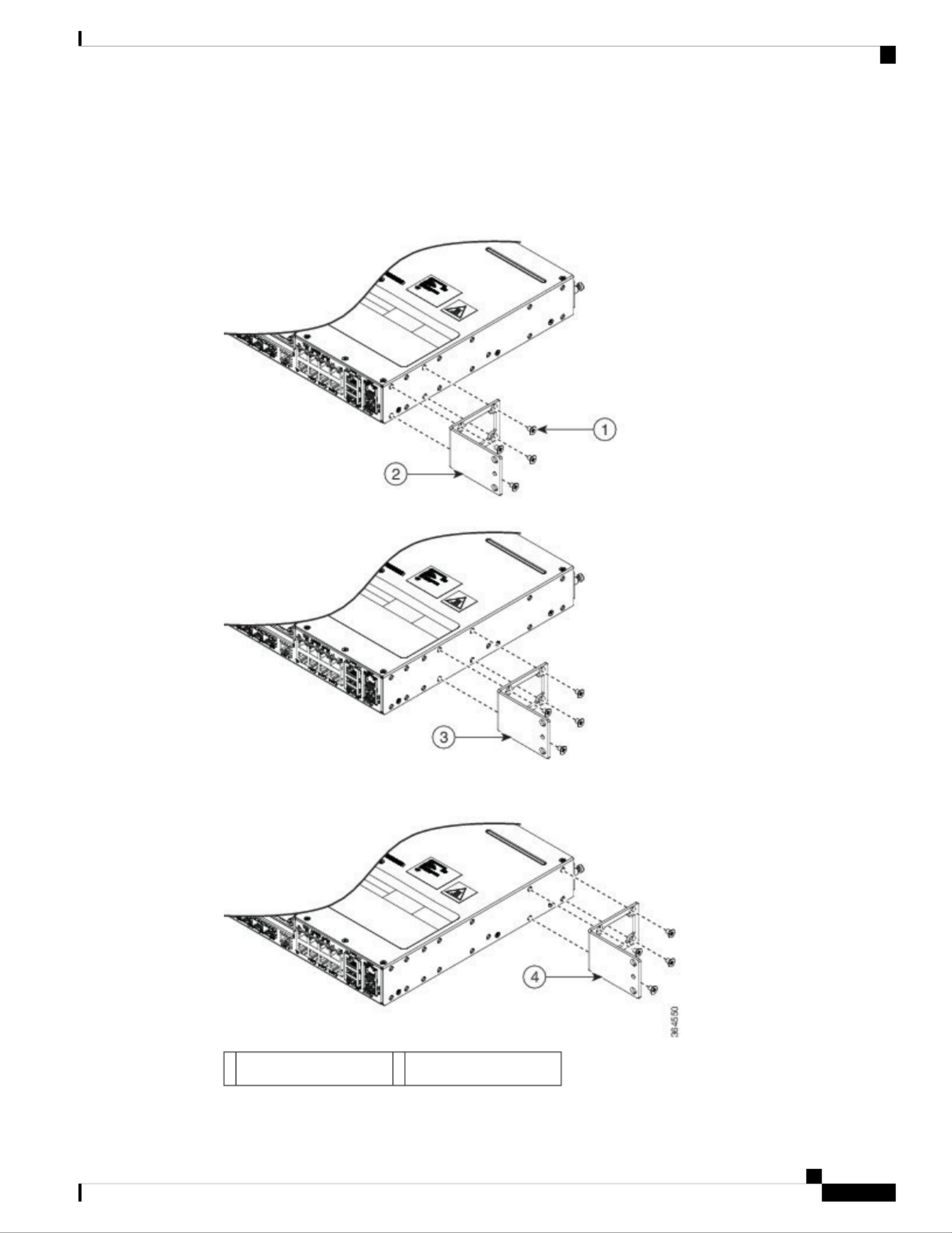
Figure 7: Attaching Brackets for 19-Inch Racks
Front-mounting position2Phillips flat-head screws1
Rear-mounting position4Mid-mounting position3
Cisco ASR-920-12SZ-IM and ASR-920-U-12SZ-IM Aggregation Services Router Hardware Installation Guide
36
Installing the Cisco ASR 920 Series Router
Attaching Brackets for 19-Inch Racks
Attaching Brackets for 23-Inch Racks
The following figure shows how to attach brackets for 23-inch racks on the router.
Figure 8: Attaching Brackets for 23-Inch Racks
Front-mounting position2Phillips flat-head screws1
Cisco ASR-920-12SZ-IM and ASR-920-U-12SZ-IM Aggregation Services Router Hardware Installation Guide
37
Installing the Cisco ASR 920 Series Router
Attaching Brackets for 23-Inch Racks

Rear-mounting position4Mid-mounting position3
Attaching Brackets for ETSI Racks
The following figure shows how to attach brackets for ETSI racks on the router.
Figure 9: Attaching Brackets for ETSI Racks
Cisco ASR-920-12SZ-IM and ASR-920-U-12SZ-IM Aggregation Services Router Hardware Installation Guide
38
Installing the Cisco ASR 920 Series Router
Attaching Brackets for ETSI Racks

Front-mounting position2Phillips flat-head screws1
Rear-mounting position4Mid-mounting position3
Mounting the Router in a Rack
Perform the steps given below to mount the router into the equipment rack.
To secure the router to the equipment rack, you must use the two mounting screws (provided) for each side
or follow your local practices for installing the router into your equipment rack. Ensure that the rack-mount
brackets are securely fastened. For more information, see the Attaching Brackets to the Router section.
Note
Procedure
Step 1 Locate the equipment rack position where you plan to install the router.
Step 2 Verify that there are no obstructions and ensure that the equipment rack is stabilized.
Step 3 Determine whether you are mounting the router on a 19-inch, 23-inch, or an ETSI rack. Rack-Mounting
Brackets figure shows the types of mounting brackets.
Step 4 Determine the mounting position (Front-, Mid-, or Rear-mounting) of the router. (For 19-inch racks, see
Attaching Brackets for 19-Inch Racks Attaching Brackets for 23-Inch Rackssection. For 23-inch racks, see
section. For ETSI racks, see section.)Attaching Brackets for ETSI Racks
Step 5 Locate the mounting holes of the router.
Step 6 Align the rack-mounting bracket with the router and position with the four #6-32 x 0.25-inch screws (provided).
Step 7 Insert the screws (four places) and tighten using a Number 2 Phillips screwdriver (each side).
Step 8 Position the router in the equipment rack lining up the bracket holes on the router with the holes on the rack
and secure with four #6-32 x 0.25-inch mounting screws (two on each side).
Step 9 Tighten the screws using a 1/4-inch flat-blade screwdriver (each side). The recommended maximum torque
is 10 in.-lb.
Installing the Router Chassis in the Rack
Ensure adequate air flow when mounting the router in a rack. For more information, see the Air Flow Guidelines
section in the Cisco ASR-920-12SZ-IM and ASR-920U-12SZ-IM Aggregation Services Router Hardware
Installation Guide.
Note
Cisco ASR-920-12SZ-IM and ASR-920-U-12SZ-IM Aggregation Services Router Hardware Installation Guide
39
Installing the Cisco ASR 920 Series Router
Mounting the Router in a Rack

Install the cable guides before installing the router in a 19-inch EIA rack. See the Attaching the Cable Guides
section in the Cisco ASR-920-12SZ-IM and ASR-920U-12SZ-IM Aggregation Services Router Hardware
Installation Guide.
Note
To install the router chassis in the equipment rack, perform these steps:
Procedure
Step 1 Position the chassis in the rack as follows:
• If the front of the chassis (front panel) is at the front of the rack, insert the rear of the chassis between
the mounting posts.
• If the rear of the chassis is at the front of the rack, insert the front of the chassis between the mounting
posts.
Step 2 Align the mounting holes in the bracket (and optional cable guide) with the mounting holes in the equipment
rack.
The following figure shows how to install the router in a 19-inch EIA rack.
Figure 10: Installing the Chassis in a 19-inch EIA Rack
Step 3 Install the four M6x12mm zinc-plated steel screws through the holes in the bracket and into the threaded holes
in the equipment rack posts.
Step 4 Use a tape measure and level to verify that the chassis is installed straight and level.
Attaching the Cable Guides
The Cisco ASR 920 Series Router supports the following cable guides:
Cisco ASR-920-12SZ-IM and ASR-920-U-12SZ-IM Aggregation Services Router Hardware Installation Guide
40
Installing the Cisco ASR 920 Series Router
Attaching the Cable Guides

• A920-CBL-GUIDE (left and right)—help in routing the cables from all components on the front panel
thereby enabling a proper cable-bending radius.
If the chassis is mounted using 19-inch brackets, you must assemble the cable guides before installing the
chassis on the rack.
Note
To install the cable guides, perform these steps:
Procedure
Step 1 Position the cable guide-left and cable guide-right against the front of the chassis and align the four screw
holes, as shown in the following figure.
Figure 11: Cable Guide Installation For 19-inch Rack Brackets
Figure 12: Cable Guide Installation For ETSI Rack Brackets
Step 2 Secure the cable guides with the four M6x12mm screws supplied with the cable kit. The recommended
maximum torque is 3N-m.
Cisco ASR-920-12SZ-IM and ASR-920-U-12SZ-IM Aggregation Services Router Hardware Installation Guide
41
Installing the Cisco ASR 920 Series Router
Attaching the Cable Guides

Figure 14: Attaching 19-inch Brackets for Wall Mounting
Mounting Router on the Wall
For the best support of the router and cables, ensure the router is attached securely to wall studs or to a firmly
attached plywood mounting backboard.
Suitable for mounting on and over a concrete or other non-combustible surface only. Statement 345
Warning
Mount the router with the front panel as shown in the following figure.
Cisco ASR-920-12SZ-IM and ASR-920-U-12SZ-IM Aggregation Services Router Hardware Installation Guide
43
Installing the Cisco ASR 920 Series Router
Mounting Router on the Wall

Installing and Removing SFP Modules
These sections describe how to install and remove SFP modules. The modules are inserted into the SFP module
slots as depicted in figure. These field-replaceable modulesInstalling an SFP Module into an SFP Module Slot
provide interfaces.
Each port must match the wavelength specifications on the other end of the cable. For reliable communications,
the cable must not exceed the stipulated cable length.
Use only Cisco SFP modules on the Cisco router. Each SFP module has an internal serial EEPROM that is
encoded with security information. This encoding provides a way for Cisco to identify and validate that the
SFP module meets the requirements for the router.
For detailed instructions on installing, removing, and cabling the SFP module, see the SFP module
documentation.
Installing SFP Modules
The following figure shows an SFP module that has a bale-clasp latch.
We strongly recommend that you do not install or remove fiber-optic SFP modules with cables attached
because of the potential damage to the cables, the cable connector, or the optical interfaces in the SFP module.
Disconnect all cables before removing or installing an SFP module.Removing and installing an SFP module
can shorten its useful life. Do not remove and insert SFP modules more often than is absolutely necessary.
Figure 16: SFP Module with a Bale-Clasp Latch
Caution
To insert an SFP module into the module slot, follow these steps:
Procedure
Step 1 Attach an ESD-preventive wrist strap to your wrist and to a bare metal surface on the chassis.
Some SFP modules identify the top side of the module with send (TX) and receive (RX) markings or arrows
that show the direction of the connection.
Step 2 If the SFP module that you are using has the markings, use them to identify the top side of the module.
Step 3 Align the SFP module in front of the slot opening.
Cisco ASR-920-12SZ-IM and ASR-920-U-12SZ-IM Aggregation Services Router Hardware Installation Guide
45
Installing the Cisco ASR 920 Series Router
Installing and Removing SFP Modules

Step 4 Insert the SFP module into the slot until you feel the connector on the module snap into place in the rear of
the slot.
Figure 17: Installing an SFP Module into an SFP Module Slot
Do not remove the dust plugs from the fiber-optic SFP module port or the rubber caps from the
fiber-optic cable until you are ready to connect the cable. The plugs and caps protect the SFP module
ports and cables from contamination and ambient light. Store the dust plugs for later use.
Caution
Step 5 Insert the cable connector into the SFP module:
• For fiber-optic SFP modules, insert the LC cable into the SFP module.
• For copper 1000BASE-T SFP modules, insert the RJ-45 cable connector into the SFP module.
Removing SFP Modules
To remove an SFP module from a module receptacle, follow these steps:
Procedure
Step 1 Attach an ESD-preventive wrist strap to your wrist and to a bare metal surface on the chassis.
Step 2 Disconnect the cable from the SFP module, and insert a dust plug into the cable end.
For reattachment, note which cable connector plug is send (TX) and which is receive (RX).
Tip
Cisco ASR-920-12SZ-IM and ASR-920-U-12SZ-IM Aggregation Services Router Hardware Installation Guide
46
Installing the Cisco ASR 920 Series Router
Removing SFP Modules
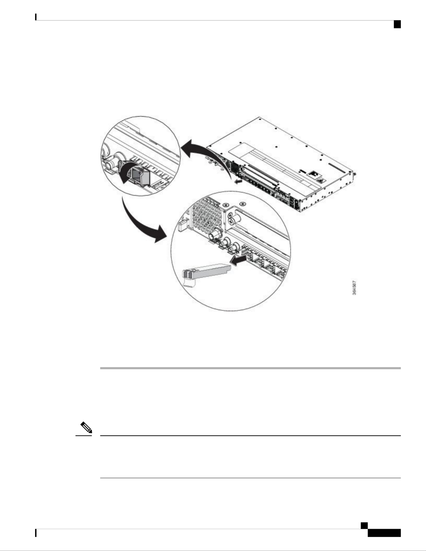
Step 3 Unlock and remove the SFP module, as shown in the following figure.
If the module has a bale-clasp latch, pull the bale out and down to eject the module. If the bale-clasp latch is
obstructed and you cannot use your index finger to open it, use a small, flat-blade screwdriver or other long,
narrow instrument to open the bale-clasp latch.
Figure 18: Removing a Bale-Clasp Latch SFP Module
Step 4 Grasp the SFP module between your thumb and index finger, and carefully remove it from the module slot.
Step 5 For fiber-optic SFP modules, insert a dust plug into the optical ports of the SFP module to keep the optical
interfaces clean.
Step 6 Place the removed SFP module in an antistatic bag or other protective environment.
Connecting to the Copper Ports
Copper ports [0:7] are capable of working 10/100/1000 Mbps.
The router copper ports configure themselves to operate at the speed of attached devices. If the attached ports
do not support autonegotiation, you can explicitly set the speed and duplex parameters. Connecting devices
that do not autonegotiate or that have their speed and duplex parameters manually set can reduce performance
or result in no linkage.
Note
To maximize performance, choose one of these methods for configuring the Ethernet ports:
Cisco ASR-920-12SZ-IM and ASR-920-U-12SZ-IM Aggregation Services Router Hardware Installation Guide
47
Installing the Cisco ASR 920 Series Router
Connecting to the Copper Ports

• Let the ports autonegotiate both speed and duplex.
• Set the port speed and duplex parameters on both ends of the connection.
Procedure
Step 1 When connecting to workstations, servers, and routers, connect a straight-through cable to an RJ-45 connector
on the front panel.When connecting to routers or repeaters, use a crossover cable.
You can use the interface configuration command in the CLI to enable the automaticmdix auto
medium-dependent interface crossover (auto-MDIX) feature. When the auto-MDIX feature is
enabled, the router detects the required cable type for copper Ethernet connections and configures
the interfaces accordingly. Therefore, you can use either a crossover or a straight-through cable for
connections to a copper 100/1000, or an SFP module port on the router, regardless of the type of
device on the other end of the connection.
Note
Step 2 Connect the other end of the cable to an RJ-45 connector on the other device. The port LED turns on when
both the router and the connected device have established link.
If the port LED does not turn on, the device at the other end might not be turned on, or there might be a cable
problem or a problem with the adapter installed in the attached device.
On user network interface (UNI) ports, the port LED is green after the link is established.
Note
Step 3 Reconfigure and reboot the connected device, if necessary.
Step 4 Repeat Steps 1 through 3 to connect each device.
Connecting to SFP Modules
This section describes how to connect to SFP modules. For instructions on how to connect to fiber-optic SFP
modules, see the Connecting to Fiber-Optic SFP Modules section.
For instructions about how to install or remove an SFP module, see the Installing and Removing SFP Modules
section.
Connecting to Fiber-Optic SFP Modules
Follow these steps to connect a fiber-optic cable to an SFP module:
Class 1 laser product. Statement 1008
Danger
Do not remove the rubber plugs from the SFP module port or the rubber caps from the fiber-optic cable until
you are ready to connect the cable. The plugs and caps protect the SFP module ports and cables from
contamination and ambient light.
Caution
Cisco ASR-920-12SZ-IM and ASR-920-U-12SZ-IM Aggregation Services Router Hardware Installation Guide
48
Installing the Cisco ASR 920 Series Router
Connecting to SFP Modules

Procedure
Step 1 Remove the rubber plugs from the module port and fiber-optic cable, and store them for future use.
Step 2 Insert one end of the fiber-optic cable into the SFP module port.
Step 3 Insert the other cable end into a fiber-optic connector on a target device.
Step 4 Observe the port status LED.
The LED turns green when the router and the target device have an established link.
If the LED is off, the target device might not be turned on, there might be a cable problem, or there might be
problem with the adapter installed in the target device.
Step 5 If necessary, reconfigure and restart the router or target device.
Installing the Chassis Ground Connection
Before you connect the power or turn on the power to the router, you must provide an adequate chassis ground
(earth) connection to your router.
This section describes how to ground the chassis. The grounding lug location is on the back panel of the router.
Ensure that the grounding lug wire does not cover the fan opening.
Tip
Figure 19: Attaching a Grounding Lug to the Rear of the Router
Grounding-lug1
To ensure that the chassis ground connection that you provide is adequate, you need the following parts and
tools:
• Ratcheting torque screwdriver with Phillips head that exerts up to 15 in.-lb (1.69 N-m) of torque for
attaching the ground wire to the router
• Crimping tool as specified by the ground lug manufacturer
• 6-AWG or larger copper wire for the ground wire
• Wire-stripping tools appropriate to the wire you are using
Before making connections to the router, ensure that you disconnect the power at the circuit breaker. Otherwise,
severe injury to you or damage to the router may occur.
Caution
Cisco ASR-920-12SZ-IM and ASR-920-U-12SZ-IM Aggregation Services Router Hardware Installation Guide
49
Installing the Cisco ASR 920 Series Router
Installing the Chassis Ground Connection

Electric Shock Hazard: This fan tray has to be serviced by trained personnel only.
Caution
This equipment must be grounded. Never defeat the ground conductor or operate the equipment in the absence
of a suitably installed ground conductor. Contact the appropriate electrical inspection authority or an electrician
if you are uncertain that suitable grounding is available. Statement 1024
Warning
Use copper conductors only. Statement 1025
Warning
When installing the unit, the ground connection must always be made first and disconnected last. Statement
42
Warning
This unit is to be installed in a restrictive access location and must be permanently grounded to a minimum
6-AWG copper ground wire.
Perform the following procedure to ground the router using a 2-hole lug and the corresponding mounting
point. Most carriers require a minimum 6-AWG ground connection. Verify your carrier’s requirements for
the ground connection.
Procedure
Step 1 If your ground wire is insulated, use a wire-stripping tool to strip the ground wire to 0.5 inch ± 0.02 inch (12.7
mm ±0.5 mm).
Figure 20: Stripping a Ground Wire
Step 2 Slide the open end of your 2-hole ground lug over the exposed area of the ground wire.
Step 3 Using a crimping tool (as specified by the ground lug manufacturer), crimp the ground lug to the ground wire
as shown in the following figure.
Cisco ASR-920-12SZ-IM and ASR-920-U-12SZ-IM Aggregation Services Router Hardware Installation Guide
50
Installing the Cisco ASR 920 Series Router
Installing the Chassis Ground Connection

Figure 21: Crimping a Ground Lug on to the Ground Wire
Step 4 Use a Phillips head screwdriver to attach the 2-hole ground lug and wire assembly to the router with the 2
pan-head Phillips head screws.
Step 5 Connect the other end of the ground wire to a suitable grounding point at your site.
Installing and Removing the Fan Tray
This section describes how to install and remove fan trays.
Installing the Fan Tray
Follow these steps to install the fan tray in the chassis:
Electric Shock Hazard: This fan tray has to be serviced by trained personnel only.
Caution
Always wear the ESD wrist strap when installing or uninstalling the fan tray.
Caution
Unplug all power sources before performing this procedure.
Caution
Procedure
Step 1 Orient the fan tray so that the captive screws are aligned to the chassis cavity on the back panel. See the
following figure.
Cisco ASR-920-12SZ-IM and ASR-920-U-12SZ-IM Aggregation Services Router Hardware Installation Guide
51
Installing the Cisco ASR 920 Series Router
Installing and Removing the Fan Tray
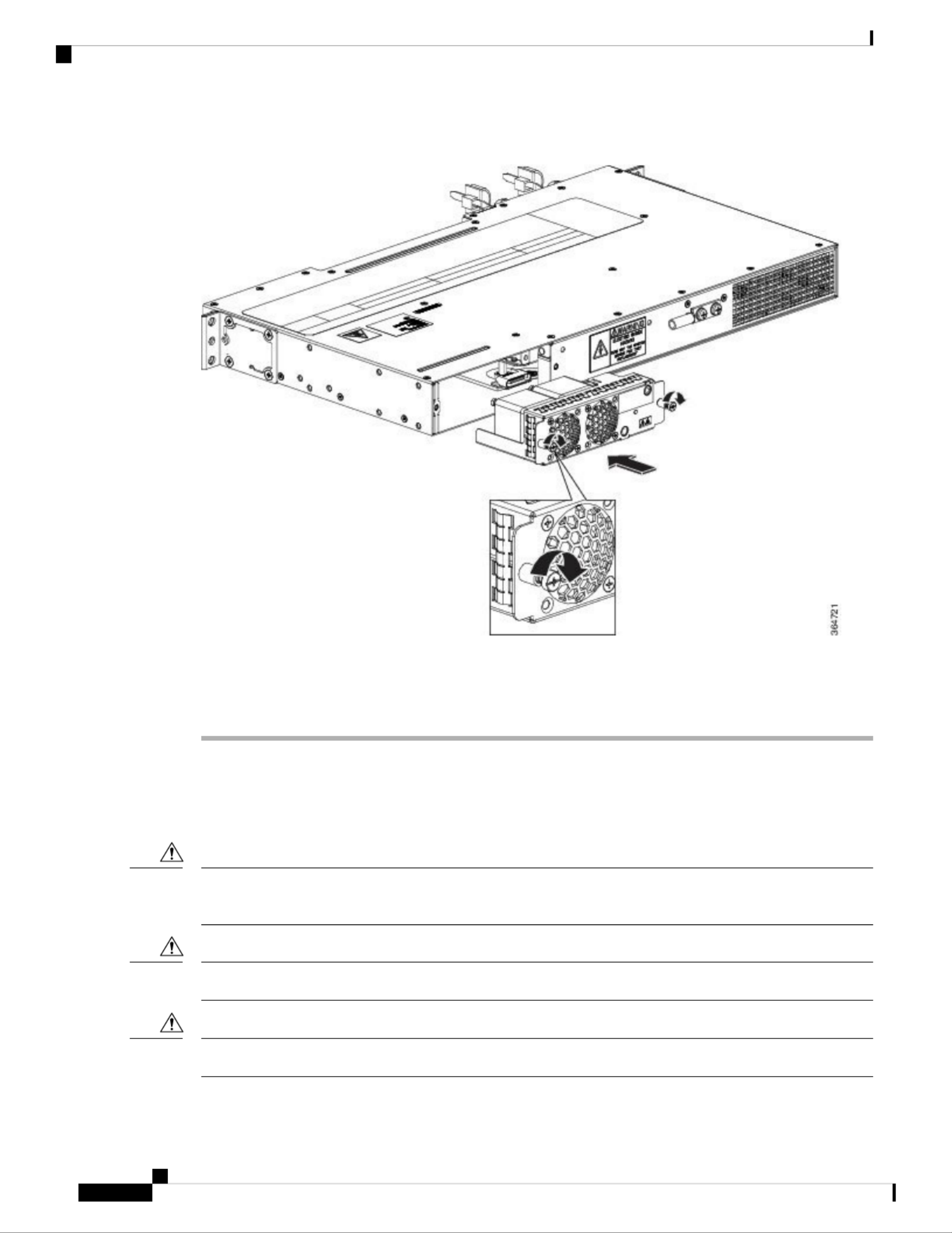
Figure 22: Installing the Fan Tray in the Chassis
Step 2 Push the fan assembly into the chassis until the power connector seats in the backplane and the captive
installation screws make contact with the chassis.
Step 3 Tighten the captive installation screws, using a flat-blade or number 2 Phillips-head screwdriver.
Removing the Fan Tray
To remove the existing fan assembly, follow these steps:
When removing the fan tray, keep your hands and fingers away from the spinning fan blades. Let the fan
blades stop completely before you remove the fan tray.
Caution
Unplug all power sources before performing this procedure.
Caution
Always wear the ESD wrist strap when installing or uninstalling the fan tray.
Caution
Cisco ASR-920-12SZ-IM and ASR-920-U-12SZ-IM Aggregation Services Router Hardware Installation Guide
52
Installing the Cisco ASR 920 Series Router
Removing the Fan Tray

Procedure
Step 1 Locate the fan assembly in the chassis. The fan tray is located to the left of the chassis on the rear side. See
the following figure.
Figure 23: Uninstalling the Fan Tray from the Chassis
Step 2 Loosen the two fan tray captive installation screws by turning them counterclockwise, using a flat-blade or
number 2 Phillips-head screwdriver.
Step 3 Grasp the fan assembly with both hands, and pull it outward; rock it gently, if necessary, to unseat the fan
assembly power connector from the backplane.
Step 4 Pull the fan assembly clear of the chassis, and set it aside.
Interface Module Installation
The following sections describe the various tasks of associated with interface module installation:
Cisco ASR-920-12SZ-IM and ASR-920-U-12SZ-IM Aggregation Services Router Hardware Installation Guide
53
Installing the Cisco ASR 920 Series Router
Interface Module Installation

Installing an Interface Module
Before inserting an interface module, make sure that the chassis is grounded.
Caution
Procedure
Step 1 To insert the interface module, carefully align the edges of the interface module between the upper and lower
edges of the router slot.
Step 2 Carefully slide the interface module into the router slot until the interface module makes contact with the
backplane.
Step 3 Tighten the locking thumbscrews on both sides of the interface module. The recommended maximum torque
is 5.5 in.-lb (.62 N-m).
Step 4 Connect all the cables to each interface module.
Removing an Interface Module
Procedure
Step 1 To remove an interface module, disconnect all the cables from the interface module.
Step 2 Loosen the locking thumbscrews on both sides of the interface module.
Step 3 Slide the interface module out of the router slot by pulling on the handles. If you are removing a blank filler
plate, pull the blank filler plate completely out of the router slot using the captive screws.
Installing Patch Panel
To install the brackets on the rear of the patch panel, perform these steps:
Procedure
Step 1 Remove the larger (M4) rack mount screws (as indicated in the Rack Mount Screws figure below) from both
sides. To secure the brackets, follow the instructions in Step-3.
Step 2 Remove the patch panel rack-mount brackets from the accessory kit and position them beside the patch panel.
Step 3 Position the brackets against the patch panel sides, and align with the screw holes. Secure the rack mount
bracket to patch panel using a torque of 13.2 in.-lb (1.5 N-m) see the figure below.
Cisco ASR-920-12SZ-IM and ASR-920-U-12SZ-IM Aggregation Services Router Hardware Installation Guide
54
Installing the Cisco ASR 920 Series Router
Installing an Interface Module

Figure 24: Rack Mount Screws
(1) Rack mount screws to secure rack mount brackets on both the sides.
Figure 25: Patch Panel Front View with Brackets
Cisco ASR-920-12SZ-IM and ASR-920-U-12SZ-IM Aggregation Services Router Hardware Installation Guide
55
Installing the Cisco ASR 920 Series Router
Installing Patch Panel

Figure 28: Patch Panel Rear View with Brackets and Guides
Step 5 Secure the guides to the brackets with the screws. The recommended maximum torque is 28 in.-lb (3.16 N-m).
Step 6 Position the patch panel with brackets and guide onto the rack and secure with screws provided. The
recommended maximum torque is 28 in.-lb (3.16 N-m), see the figure below.
Cisco ASR-920-12SZ-IM and ASR-920-U-12SZ-IM Aggregation Services Router Hardware Installation Guide
57
Installing the Cisco ASR 920 Series Router
Installing Patch Panel

Figure 29: Patch Panel Front View with Brackets and Guides Installed on Rack
Cisco ASR-920-12SZ-IM and ASR-920-U-12SZ-IM Aggregation Services Router Hardware Installation Guide
58
Installing the Cisco ASR 920 Series Router
Installing Patch Panel
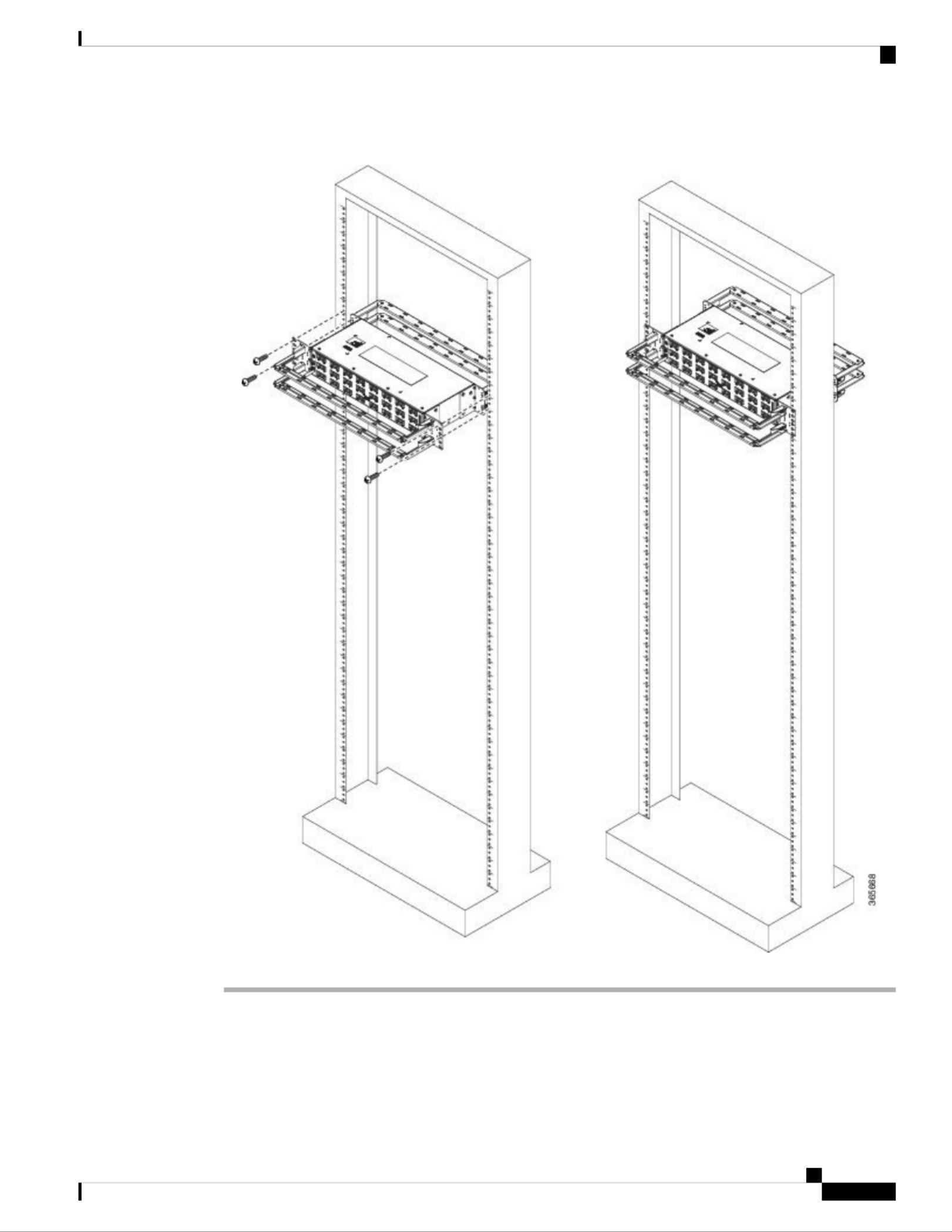
Figure 30: Patch Panel Rear View with Brackets and Guides Installed on Rack
Install 3G Patch Panel
You can choose to either set up the Cisco ASR 903 3G patch panel on a rack or wall mount it.
Cisco ASR-920-12SZ-IM and ASR-920-U-12SZ-IM Aggregation Services Router Hardware Installation Guide
59
Installing the Cisco ASR 920 Series Router
Install 3G Patch Panel

Install Rack Brackets
Procedure
Step 1 Connect the grounding lugs using a crimping tool (as specified by the ground lug manufacturer), crimp the
ground lug to the ground wire.
Step 2 Use a 6 AWG ground wire to connect the other end to a suitable grounding point at your site.
Figure 31: Patch Panel Grounding - Single
Cisco ASR-920-12SZ-IM and ASR-920-U-12SZ-IM Aggregation Services Router Hardware Installation Guide
60
Installing the Cisco ASR 920 Series Router
Install Rack Brackets

Figure 32: Patch Panel Grounding - Dual
Step 3 Position the patch panel in the rack as follows:
• If the front of the patch panel is at the front of the rack, insert the rear of the chassis between the mounting
posts.
• If the rear of the patch panel is at the front of the rack, insert the front of the chassis between the mounting
posts.
Step 4 Align the mounting holes in the bracket with the mounting holes in the equipment rack.
Cisco ASR-920-12SZ-IM and ASR-920-U-12SZ-IM Aggregation Services Router Hardware Installation Guide
61
Installing the Cisco ASR 920 Series Router
Install Rack Brackets
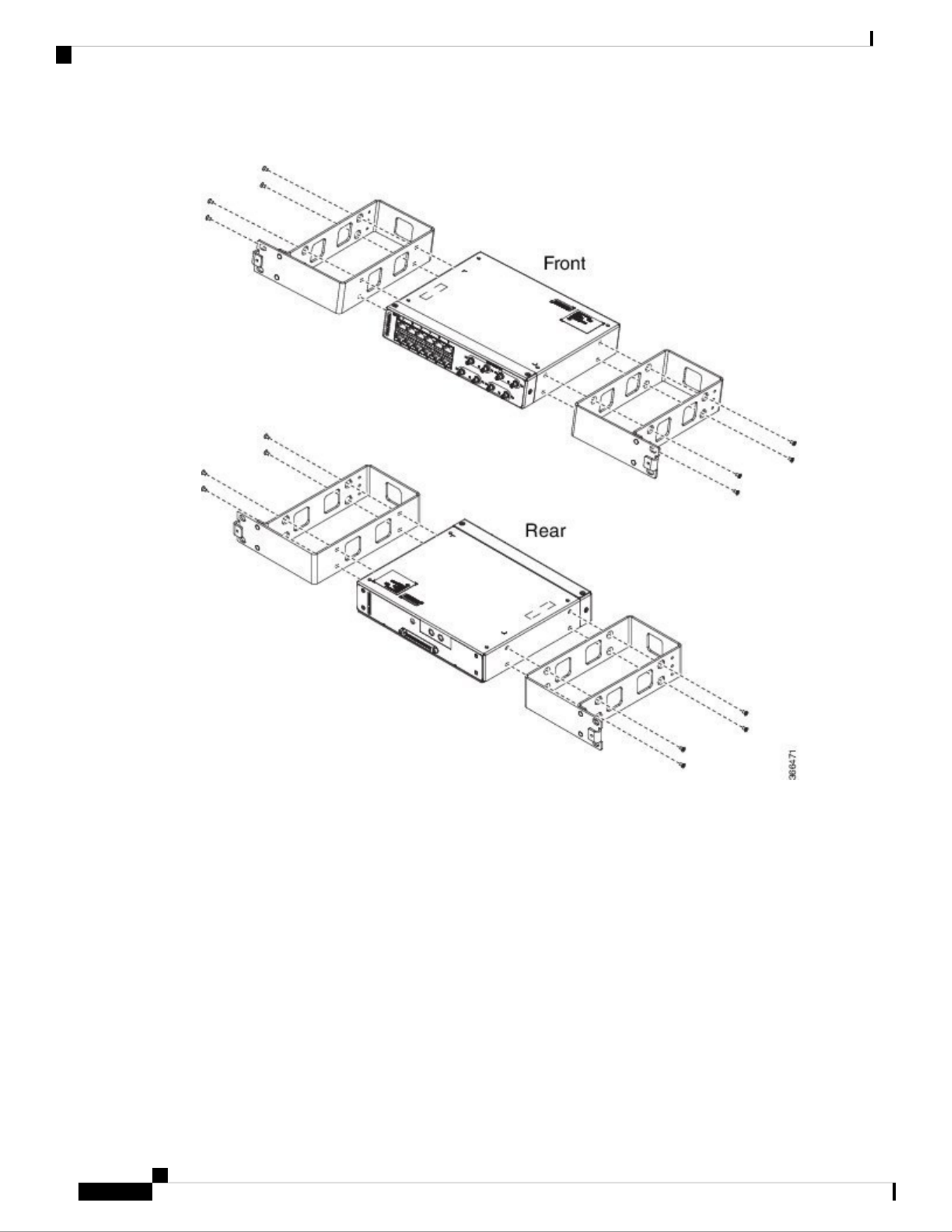
Figure 33: Installing the Patch Panel - Single in a 19-inch Rack
Cisco ASR-920-12SZ-IM and ASR-920-U-12SZ-IM Aggregation Services Router Hardware Installation Guide
62
Installing the Cisco ASR 920 Series Router
Install Rack Brackets

Figure 34: Installing the Patch Panel - Dual in a 19-inch Rack
Cisco ASR-920-12SZ-IM and ASR-920-U-12SZ-IM Aggregation Services Router Hardware Installation Guide
63
Installing the Cisco ASR 920 Series Router
Install Rack Brackets

Figure 35: Installing the Patch Panel - Single in a 21-inch Rack
Cisco ASR-920-12SZ-IM and ASR-920-U-12SZ-IM Aggregation Services Router Hardware Installation Guide
64
Installing the Cisco ASR 920 Series Router
Install Rack Brackets
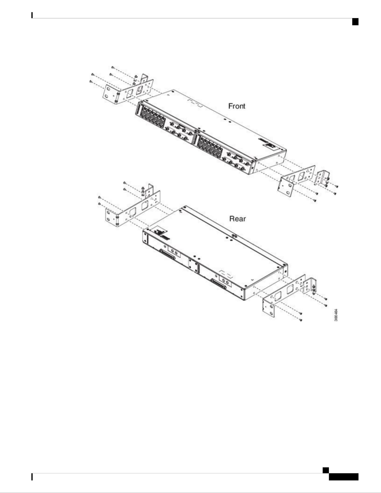
Figure 36: Installing the Patch Panel - Dual in a 21-inch Rack
Cisco ASR-920-12SZ-IM and ASR-920-U-12SZ-IM Aggregation Services Router Hardware Installation Guide
65
Installing the Cisco ASR 920 Series Router
Install Rack Brackets

Figure 38: Installing the Patch Panel - Dual in a 23-inch Rack
Step 5 Secure the brackets to the chassis with the screws. The recommended maximum torque is 28 in.-lb (3.16
N-m).
• EIA 19 and 23 inches mounting brackets for both single and double 3G interface module patch panels.
• ETSI 21 inches mounting brackets for both single and double 3G interface module patch panels.
Set up 3G Patch Panel on Rack
To install the optional cable management brackets, perform these steps:
Procedure
Step 1 Position the cable management brackets against the front of the chassis and align the screw holes, as shown
in the figure.
Step 2 Secure the cable management brackets with the screws. The recommended maximum torque is 10 in.-lb (1.12
N-m).
Cisco ASR-920-12SZ-IM and ASR-920-U-12SZ-IM Aggregation Services Router Hardware Installation Guide
67
Installing the Cisco ASR 920 Series Router
Set up 3G Patch Panel on Rack

Figure 39: Attaching 19-inch Brackets to Patch Panel - Single
Cisco ASR-920-12SZ-IM and ASR-920-U-12SZ-IM Aggregation Services Router Hardware Installation Guide
68
Installing the Cisco ASR 920 Series Router
Set up 3G Patch Panel on Rack

Figure 40: Installing 19-inch Brackets on to Rack - Single
Cisco ASR-920-12SZ-IM and ASR-920-U-12SZ-IM Aggregation Services Router Hardware Installation Guide
69
Installing the Cisco ASR 920 Series Router
Set up 3G Patch Panel on Rack
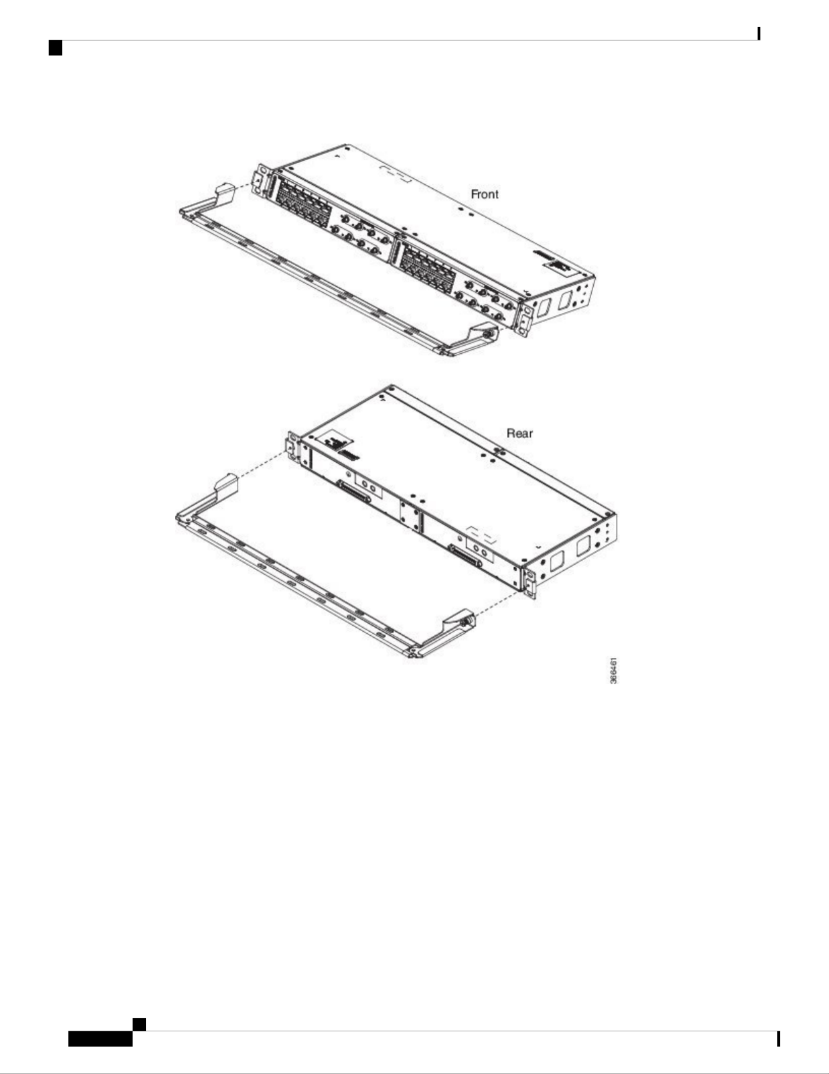
Figure 41: Attaching 19-inch Brackets to Patch Panel - Dual
Cisco ASR-920-12SZ-IM and ASR-920-U-12SZ-IM Aggregation Services Router Hardware Installation Guide
70
Installing the Cisco ASR 920 Series Router
Set up 3G Patch Panel on Rack

Figure 42: Installing 19-inch Brackets on to Rack - Dual
Cisco ASR-920-12SZ-IM and ASR-920-U-12SZ-IM Aggregation Services Router Hardware Installation Guide
71
Installing the Cisco ASR 920 Series Router
Set up 3G Patch Panel on Rack

Figure 43: Attaching 21-inch Brackets to Patch Panel - Single
Cisco ASR-920-12SZ-IM and ASR-920-U-12SZ-IM Aggregation Services Router Hardware Installation Guide
72
Installing the Cisco ASR 920 Series Router
Set up 3G Patch Panel on Rack

Figure 44: Installing 21-inch Brackets on to Rack - Single
Cisco ASR-920-12SZ-IM and ASR-920-U-12SZ-IM Aggregation Services Router Hardware Installation Guide
73
Installing the Cisco ASR 920 Series Router
Set up 3G Patch Panel on Rack

Figure 46: Installing 21-inch Brackets on to Rack - Dual
Cisco ASR-920-12SZ-IM and ASR-920-U-12SZ-IM Aggregation Services Router Hardware Installation Guide
75
Installing the Cisco ASR 920 Series Router
Set up 3G Patch Panel on Rack

Figure 47: Attaching 23-inch Brackets to Patch Panel - Single
Cisco ASR-920-12SZ-IM and ASR-920-U-12SZ-IM Aggregation Services Router Hardware Installation Guide
76
Installing the Cisco ASR 920 Series Router
Set up 3G Patch Panel on Rack

Figure 49: Attaching 23-inch Brackets to Patch Panel - Dual
Cisco ASR-920-12SZ-IM and ASR-920-U-12SZ-IM Aggregation Services Router Hardware Installation Guide
78
Installing the Cisco ASR 920 Series Router
Set up 3G Patch Panel on Rack
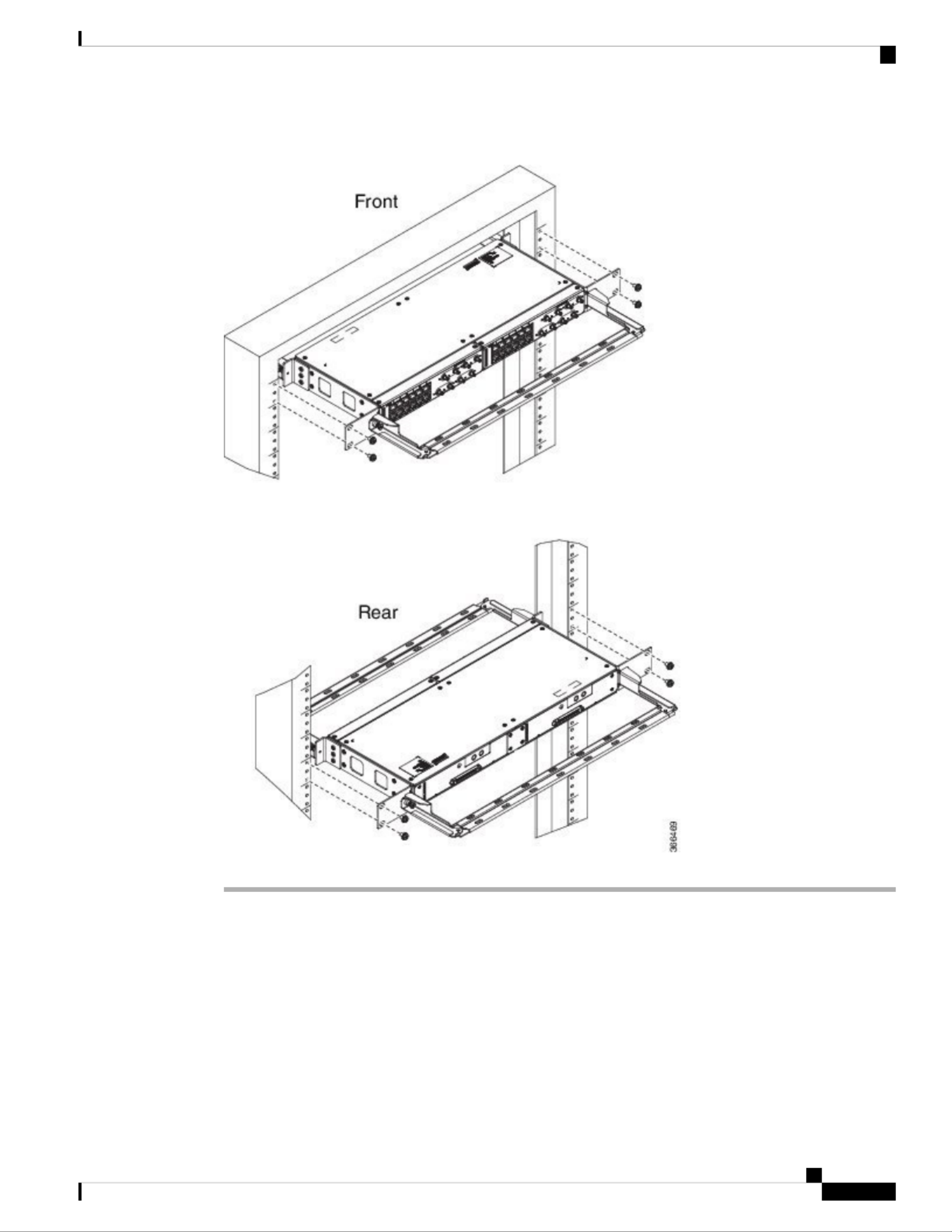
Figure 50: Installing 23-inch Brackets on to Rack - Dual
Wall Mount 3G Patch Panel
Before you begin
You must first install the mounting brackets and cable guides on to the patch panel before you mount it on
the wall. You can use the same rack mount brackets (700-113653-01) for wall mount.
Cisco ASR-920-12SZ-IM and ASR-920-U-12SZ-IM Aggregation Services Router Hardware Installation Guide
79
Installing the Cisco ASR 920 Series Router
Wall Mount 3G Patch Panel
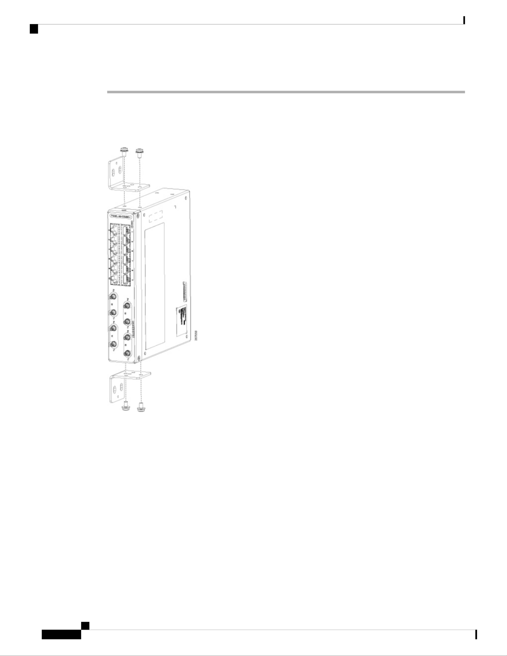
Procedure
Step 1 Remove the mounting brackets from the accessory kit and position them beside the device.
You can install the brackets as shown in the figure.
Note
Figure 51: Wall Mount - Single
Cisco ASR-920-12SZ-IM and ASR-920-U-12SZ-IM Aggregation Services Router Hardware Installation Guide
80
Installing the Cisco ASR 920 Series Router
Wall Mount 3G Patch Panel
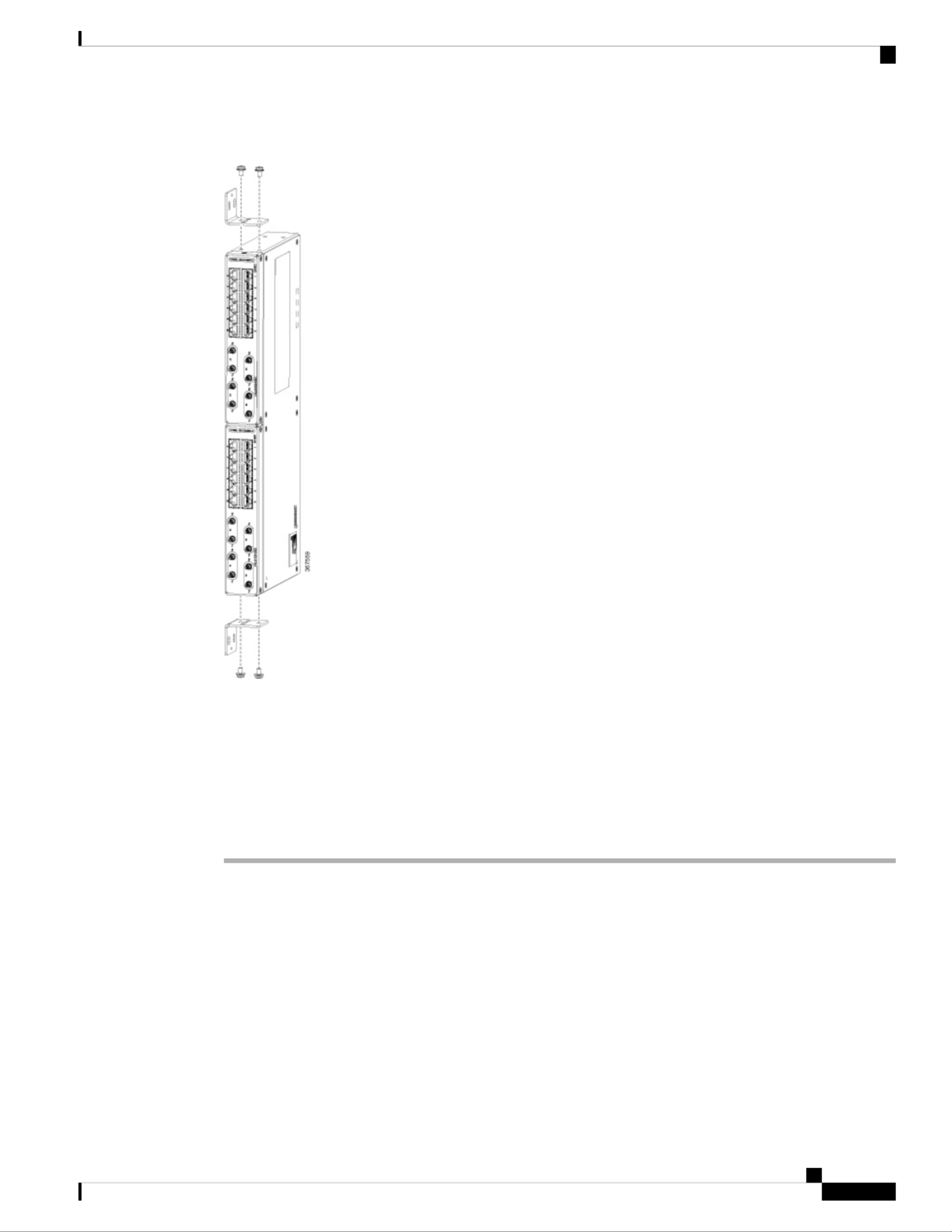
Figure 52: Wall Mount - Dual
Step 2 Secure the bracket to the device with the recommended maximum torque of 10 inch-pounds (1.1 newton
meters).
Step 3 Position the device vertically on the wall.
Before mounting the device, ensure that all unused holes at the sides of the device are protected
with screws.
Caution
Step 4 Use a tape measure and level to verify that the device is installed straight and on level.
Patch Panel Dimensions
Following are the various patch panel dimensions.
Cisco ASR-920-12SZ-IM and ASR-920-U-12SZ-IM Aggregation Services Router Hardware Installation Guide
81
Installing the Cisco ASR 920 Series Router
Patch Panel Dimensions

Figure 53: Patch Panel Without Brackets
Cisco ASR-920-12SZ-IM and ASR-920-U-12SZ-IM Aggregation Services Router Hardware Installation Guide
82
Installing the Cisco ASR 920 Series Router
Patch Panel Dimensions

Figure 54: Patch Panel With Brackets
Cisco ASR-920-12SZ-IM and ASR-920-U-12SZ-IM Aggregation Services Router Hardware Installation Guide
83
Installing the Cisco ASR 920 Series Router
Patch Panel Dimensions

Figure 55: AMP64 Patch Panel With Brackets
Cisco ASR-920-12SZ-IM and ASR-920-U-12SZ-IM Aggregation Services Router Hardware Installation Guide
84
Installing the Cisco ASR 920 Series Router
Patch Panel Dimensions

Figure 56: 3G Patch Panel Without Brackets - Single
Cisco ASR-920-12SZ-IM and ASR-920-U-12SZ-IM Aggregation Services Router Hardware Installation Guide
85
Installing the Cisco ASR 920 Series Router
Patch Panel Dimensions

Figure 57: 3G Patch Panel Without Brackets - Dual
Patch Panel Pinout
Given below are the pinout information for the regular crossover and the straight-through cable patch panel.
Table 16: Pinout Details
Straight-throughCrossoverPin
#
Transmit TipReceive Tip1
Transmit RingReceive Ring2
——3
Receive TipTransmit Tip4
Receive RingTransmit
Ring
5
——6
——7
——8
Cisco ASR-920-12SZ-IM and ASR-920-U-12SZ-IM Aggregation Services Router Hardware Installation Guide
86
Installing the Cisco ASR 920 Series Router
Patch Panel Pinout

Read the installation instructions before connecting the system to the power source. Statement 10
Warning
Products that have an AC power connection are required to have an external surge protective device (SPD)
provided as part of the building installation to comply with the Telcordia GR-1089 NEBS standard for
electromagnetic compatibility and safety.
Note
Do not use interface module and power supply ejector handles to lift the chassis; using the handles to lift the
chassis can deform or damage the handles.
Caution
Power Connection Guidelines
This section provides guidelines for connecting the router’s power supplies to the site power source.
Never defeat the ground conductor or operate the equipment in the absence of a suitably installed ground
conductor. Contact the appropriate electrical inspection authority or an electrician if you are uncertain that
suitable grounding is available. Statement 213
Warning
The plug-socket combination must be accessible at all times because it serves as the main disconnecting
device. Statement 1019
Warning
This product requires short-circuit (overcurrent) protection, to be provided as part of the building installation.
Install only in accordance with national and local wiring regulations. Statement 1045
Warning
Guidelines for DC-Powered Systems
Basic guidelines for DC-powered systems include the following:
• Each chassis power supply should have its own dedicated input power source. The source must comply
with the safety extra-low voltage (SELV) requirements in the UL 60950, CSA 60950, EN 60950, and
IEC 60950 standards.
• The circuit must be protected by a dedicated two-pole circuit breaker. The circuit breaker should be sized
according to the power supply input rating and local or national code requirements.
• The circuit breaker is considered the disconnect device and should be easily accessible.
• The system ground is the power supply and chassis ground.
• Do not connect the DC return wire to the system frame or to the system-grounding equipment.
• Use the grounding lug to attach a wrist strap for ESD protection during servicing.
Cisco ASR-920-12SZ-IM and ASR-920-U-12SZ-IM Aggregation Services Router Hardware Installation Guide
88
Installing the Cisco ASR 920 Series Router
Power Connection Guidelines

• If the chassis is powered with -48V grounding of the positive, the it should be done at the power source
side and chassis should protected by a dedicated two-pole circuit breaker.
Guidelines for AC-Powered Systems
Basic guidelines for AC-powered systems include the following:
• Each chassis power supply should have its own dedicated branch circuit.
• The circuit breaker should be sized according to the power supply input rating and local or national code
requirements.
• The AC power receptacles used to plug in the chassis must be the grounding type. The grounding
conductors that connect to the receptacles should connect to protective earth ground at the service
equipment.
Preventing Power Loss
Use the following guidelines to prevent power loss to the router:
• To prevent loss of input power, ensure that the total maximum load on each circuit supplying the power
supplies is within the current ratings of the wiring and breakers.
• In some systems, you can use an UPS to protect against power failures at your site. Avoid UPS types
that use ferroresonant technology. These UPS types can become unstable with systems such as the Cisco
ASR 920 Series Router, which can have substantial current-draw fluctuations due to bursty data traffic
patterns.
Use the information in the table to estimate the powerCisco ASR-920-12SZ-IM Router Specications
requirements and heat dissipation of the router based on a given configuration of the router. Determining
power requirements is useful for planning the power distribution system needed to support the router.
Installing the DC Power Supply Module
This equipment is suitable for installation in Network Telecommunications Facilities and locations where the
NEC applies.
This equipment is suitable for installations utilizing the Common Bonding Network (CBN).
The grounding architecture of this product is DC-Isolated (DC-I) for DC-powered products. DC-powered
products have a nominal operating DC voltage of 48 VDC.
Perform the following procedure to install the power supply module:
Procedure
Step 1 Ensure that the system (earth) ground connection has been made. See the following figure.
Step 2 If necessary, remove the blank power supply filler plate from the chassis power supply bay opening by
loosening the captive installation screws.
Step 3 Verify that power to the DC circuit connected to the power supply you are installing is off. To ensure that
power has been removed from the DC circuits, locate the circuit breakers for the DC circuits, switch the circuit
breakers to the OFF position, and tape the circuit-breaker switches in the OFF position.
Step 4 Grasp the power supply handle with one hand. Place your other hand underneath the power supply. Slide the
power supply into the power supply bay. Make sure that the power supply is fully seated in the bay.
Cisco ASR-920-12SZ-IM and ASR-920-U-12SZ-IM Aggregation Services Router Hardware Installation Guide
89
Installing the Cisco ASR 920 Series Router
Guidelines for AC-Powered Systems

If you are connecting a redundant DC power supply, ensure that each power supply is connected
to a separate power source in order to prevent power loss in the event of a power failure.
Note
Install the DC Power Cables
When installing DC power supply, use 12AWG, 90°C temperature rated cable. The recommanded cable length
is 3 meters maximum from source. Up to 5 meters use 10AWG, and up to 3 meters use 12AWG, 90°C
temperature rated cable and for other length contact Cisco.
Note
• Always ensure that the building’s installation for short-circuit (overcurrent) protection does not exceed
15A.
• We recommended using a Circuit breaker or a fast acting fuse with a maximum DC rating of 10A for
over current protection.
Note
The DC connector or terminal block has an in built screw and cage nut to which torque of 1.3 to 1.8 N-m can
be applied.
Note
Figure 59: DC Connector with In built Screw
0.27 in. (0.68 cm)C0.97 in. (2.4 cm)A
0.17 in. (0.43 cm)D0.31 in. (0.78
cm)
B
0.81 in. (2 cm)M
Cisco ASR-920-12SZ-IM and ASR-920-U-12SZ-IM Aggregation Services Router Hardware Installation Guide
91
Installing the Cisco ASR 920 Series Router
Install the DC Power Cables

Figure 60: DC Connector with In built Screw for N540X-16Z4G8Q2C-D
0.18 in. (0.46 cm)C0.74 in. (1.88
cm)
A
0.14 in. (0.36 cm)D0.25 in. (0.64
cm)
B
0.62 in. (1.58
cm)
M
To attach the DC power supplies:
Procedure
Step 1 Locate the terminal block plug.
Step 2 Insert the DC-input power source wires into the terminal block plug.
Step 3 Attach the DC supply wires using the designated screws.
Step 4 Use a ratcheting torque screwdriver to torque the terminal block plug captive screw. See the following figure.
Cisco ASR-920-12SZ-IM and ASR-920-U-12SZ-IM Aggregation Services Router Hardware Installation Guide
92
Installing the Cisco ASR 920 Series Router
Install the DC Power Cables

Figure 61: Attach the DC Power Supply Wires
These images are for only representation purposes. Certain variants of Cisco NCS 540 may vary.
Note
Removing the DC Power Supply Module
This section provides information about removing and replacing the DC power supply.
Before performing any of the following procedures, ensure that power is removed from the DC circuit.
Statement 1003
Warning
Only trained and qualified personnel should be allowed to install, replace, or service this equipment. Statement
1030
Warning
Follow these steps to remove and replace the DC power supply:
Procedure
Step 1 Before servicing the power supply, switch off the circuit breaker in your equipment area. As an additional
precaution, tape the circuit-breaker switch in the Off position.
Cisco ASR-920-12SZ-IM and ASR-920-U-12SZ-IM Aggregation Services Router Hardware Installation Guide
93
Installing the Cisco ASR 920 Series Router
Removing the DC Power Supply Module

Step 2 Slip on the ESD-preventive wrist strap that was included in the accessory kit.
Step 3 Switch the power supply circuit-breaker switch to the Off (O) position.
Step 4 Pull the terminal block plug connector out of the terminal block head in the power supply. See the following
figure.
Step 5 Loosen the captive screws on the DC power supply.
Step 6 Grasp the power supply handle. Simultaneously press the power supply lock towards the left and pull the
power supply out from the chassis while supporting it with the other hand.
Figure 62: Removing the DC Power Supply Module
Installing the AC Power Supply Module
Follow these steps to install the AC power supply module:
Procedure
Step 1 Ensure that the system (earth) ground connection has been made.
Step 2 If necessary, remove the blank power supply filler plate from the chassis power supply bay opening by
loosening the captive installation screws.
Cisco ASR-920-12SZ-IM and ASR-920-U-12SZ-IM Aggregation Services Router Hardware Installation Guide
94
Installing the Cisco ASR 920 Series Router
Installing the AC Power Supply Module
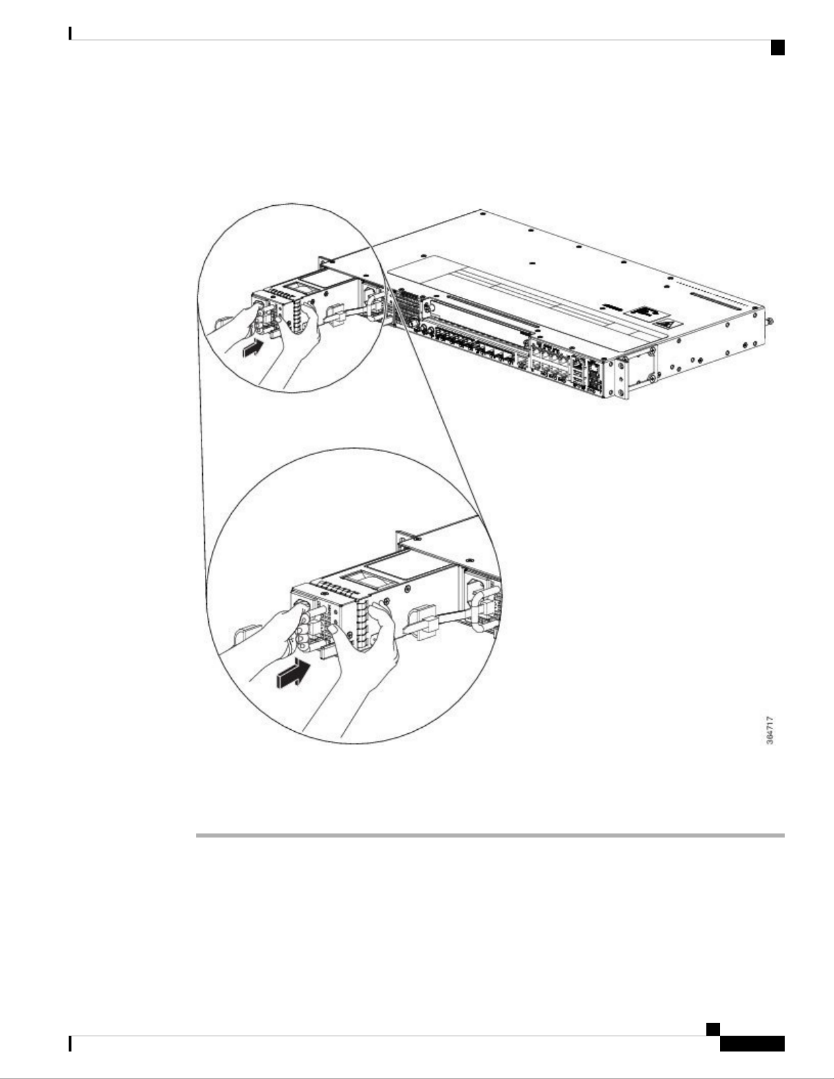
Step 3 Grasp the power supply handle with one hand. Place your other hand underneath the power supply. Slide the
power supply into the power supply bay. Make sure that the power supply is fully seated in the bay. See the
following figure.
Figure 63: Installing the AC Power Supply Module
Step 4 Slide the AC power supply cord inside the tie of the tie-and-holder and tighten the tie around the power supply
cord.
Step 5 Plug the power supply cord into the AC power supply.
Install the AC Power Cables
To install the AC power cables in the power supply slots:
Cisco ASR-920-12SZ-IM and ASR-920-U-12SZ-IM Aggregation Services Router Hardware Installation Guide
95
Installing the Cisco ASR 920 Series Router
Install the AC Power Cables

Step 2 Connect the other end of the power cord to an AC-input power source.
Step 3 Verify power supply operation by checking if the respective power supply front panel LED (PS0 or PS1) is
green.
Step 4 If the LEDs indicate a power problem, see Troubleshooting for troubleshooting information.
Step 5 If you are connecting a redundant AC power supply, repeat these steps for the second power source.
If you are connecting a redundant AC power supply, ensure that each power supply is connected
to a separate power source in order to prevent power loss in the event of a power failure.
Note
Removing the AC Power Supply Module
This section describes how to remove and replace the AC power supply.
When you install the unit, the ground connection must always be made first and disconnected last. Statement
1046
Warning
Only trained and qualified personnel should be allowed to install, replace, or service this equipment. Statement
1030
Warning
Installation of the equipment must comply with local and national electrical codes. Statement 1074
Warning
Follow these steps to remove and replace the AC power supply:
Procedure
Step 1 Disconnect the power cord from the power source. Do not touch any metal on the power cord when it is still
connected to the power supply.
Step 2 Loosen the tie and remove the power cord from the tie-and holder.
Step 3 Remove the power cord from the power connection on the power supply. Do not touch the metal prongs
embedded in the power supply.
Step 4 Grasp the power supply handle. Simultaneously press the power supply lock towards the left and pull the
power supply out from the chassis while supporting it with the other hand.
Cisco ASR-920-12SZ-IM and ASR-920-U-12SZ-IM Aggregation Services Router Hardware Installation Guide
97
Installing the Cisco ASR 920 Series Router
Removing the AC Power Supply Module

Figure 65: Removing the AC Power Supply Module
Powering On the Router
After the router is either rack mounted or mounted on the wall, perform these tasks to complete the installation:
• Power on the router.
• Connect the front-panel ports. See the section to complete the installation.Connecting to SFP Modules
Connecting the Router to the Network
The sections describe how to connect a router to the network:
Connect only SELV services to all the ports.
Note
Cisco ASR-920-12SZ-IM and ASR-920-U-12SZ-IM Aggregation Services Router Hardware Installation Guide
98
Installing the Cisco ASR 920 Series Router
Powering On the Router
Produktspezifikationen
| Marke: | Cisco |
| Kategorie: | Router |
| Modell: | ASR-920-12SZ-IM |
| Breite: | 444.5 mm |
| Tiefe: | 286.54 mm |
| Gewicht: | 4830 g |
| Produktfarbe: | Grau |
| Höhe: | 44 mm |
| Energiequelle: | AC, DC, PoE |
| AC Eingangsspannung: | 100 - 240 V |
| AC Eingangsfrequenz: | 50 - 60 Hz |
| Antennentyp: | Nicht unterstützt |
| Betriebstemperatur: | -40 - 70 °C |
| Relative Luftfeuchtigkeit in Betrieb: | 5 - 95 % |
| Netzstandard: | IEEE 802.3x |
| Unterstützte Sicherheitsalgorithmen: | IPSec |
| Quality of Service (QoS) Support: | Ja |
| Eingebauter Ethernet-Anschluss: | Ja |
| Stromverbrauch (Standardbetrieb): | 130 W |
| Power over Ethernet (PoE): | Ja |
| Anzahl Ethernet-LAN-Anschlüsse (RJ-45): | 8 |
| Ethernet LAN Datentransferraten: | 10,100,1000,10000 Mbit/s |
| LED-Anzeigen: | Ja |
| Temperaturbereich bei Lagerung: | -40 - 70 °C |
| RS-232 port: | 2 |
| Routing-/Switching-Kapazität: | 64 Gbit/s |
| Rack-Einbau: | Ja |
| Anzahl der USB-Anschlüsse: | 2 |
| Web-basiertes Management: | Ja |
| Anzahl Gigabit Ethernet (Kupfer) Anschlüsse: | 8 |
| Mittlere Betriebsdauer zwischen Ausfällen (MTBF): | 407230 h |
| Ethernet-WAN: | Ja |
| DSL-WAN: | Nein |
| SIM-Karten-Slot: | Nein |
| 3G/4G USB Modem-Kompatibilität: | Nein |
| Wandmontage: | Ja |
| Sicherheit: | UL 60950-1, 2005, CAN/CSA C22.2 No. 60950-1: 2005, IEC 60950-1, 2005, EN 60950-1, 2005, AS/NZS 60950.1:2005 |
| Zugriffkontrollliste: | Ja |
| Rack-Kapazität: | 1U |
| Höhe bei Lagerung: | 0 - 4570 m |
| Elektromagnetische Verträglichkeit: | FCC CFR47 Part 15 Class A |
| Anzahl Power over Ethernet (PoE) Anschlüsse: | 8 |
| Hot-Swap: | Ja |
| Anzahl der Schaltgewebeschlitze: | 8 |
Brauchst du Hilfe?
Wenn Sie Hilfe mit Cisco ASR-920-12SZ-IM benötigen, stellen Sie unten eine Frage und andere Benutzer werden Ihnen antworten
Bedienungsanleitung Router Cisco

2 Oktober 2024
2 September 2024
27 August 2024
26 August 2024
26 August 2024
25 August 2024
24 August 2024
4 August 2024
3 August 2024
2 August 2024
Bedienungsanleitung Router
- Router Acer
- Router Anker
- Router Apple
- Router Approx
- Router Asus
- Router Belkin
- Router BenQ
- Router Exibel
- Router Gembird
- Router Gigabyte
- Router Hama
- Router HP
- Router LogiLink
- Router Manhattan
- Router Medion
- Router Sweex
- Router Trust
- Router Clas Ohlson
- Router Cotech
- Router Makita
- Router Roland
- Router ZyXEL
- Router Bosch
- Router Alfa
- Router Siemens
- Router Buffalo
- Router TechniSat
- Router Allnet
- Router Devolo
- Router Eminent
- Router Linksys
- Router Netgear
- Router Telekom
- Router König
- Router Renkforce
- Router Thomson
- Router Black And Decker
- Router Skil
- Router Kenwood
- Router Schneider
- Router DeWalt
- Router Einhell
- Router Festool
- Router Topcom
- Router Nilox
- Router Motorola
- Router Nokia
- Router Vivanco
- Router Xiaomi
- Router EZVIZ
- Router Hikoki
- Router Hitachi
- Router Strong
- Router TCL
- Router Metabo
- Router Zoom
- Router Güde
- Router Netis
- Router Aruba
- Router Lindy
- Router Thrustmaster
- Router MSI
- Router Mercusys
- Router Razer
- Router TRENDnet
- Router Sagem
- Router Sigma
- Router Western Digital
- Router AVM
- Router Milan
- Router Zebra
- Router EnVivo
- Router TP-Link
- Router Kathrein
- Router Silverline
- Router Holzmann
- Router Alcatel
- Router Vtech
- Router Black Box
- Router Techly
- Router Barco
- Router Hercules
- Router Milwaukee
- Router Toolcraft
- Router Huawei
- Router JUNG
- Router Nest
- Router Edimax
- Router DrayTek
- Router Eumex
- Router Technicolor
- Router Totolink
- Router Kogan
- Router Peak
- Router Sagemcom
- Router Conceptronic
- Router D-Link
- Router T-Mobile
- Router I-Tec
- Router QNAP
- Router Icidu
- Router Vodafone
- Router Powerplus
- Router Digitus
- Router Lancom
- Router LevelOne
- Router Beafon
- Router Phicomm
- Router ZTE
- Router Sonos
- Router Tenda
- Router Kasda
- Router Foscam
- Router Ubiquiti Networks
- Router Synology
- Router Kopul
- Router Kramer
- Router Intellinet
- Router Asrock
- Router AJA
- Router Hikvision
- Router Patton
- Router Nexxt
- Router Planet
- Router AT&T
- Router EnGenius
- Router Mikrotik
- Router Teltonika
- Router Porter-Cable
- Router Google
- Router Comtrend
- Router Davolink
- Router Digi
- Router Digiconnect
- Router KPN
- Router Leoxsys
- Router Media-tech
- Router Mercku
- Router On Networks
- Router PENTAGRAM
- Router Proximus
- Router Sitecom
- Router SMC
- Router T-com
- Router Tele 2
- Router Telstra
- Router Ubee
- Router United Telecom
- Router UPC
- Router Verizon
- Router Wintec
- Router Wisetiger
- Router Zolid
- Router Vimar
- Router Cudy
- Router Siig
- Router Moxa
- Router RGBlink
- Router Iogear
- Router StarTech.com
- Router Kraun
- Router AirLive
- Router Smart-AVI
- Router Dahua Technology
- Router ModeCom
- Router Gefen
- Router Atlantis Land
- Router BT
- Router Cradlepoint
- Router Multitech
- Router Arris
- Router ATen
- Router KanexPro
- Router SPL
- Router Advantech
- Router RAVPower
- Router Digicom
- Router Juniper
- Router BZBGear
- Router Brickcom
- Router 3Com
- Router B&B Electronics
- Router Eero
- Router Atlona
- Router Xantech
- Router WyreStorm
- Router AVMATRIX
- Router Alfatron
- Router Key Digital
- Router Rosewill
- Router HiRO
- Router Ocean Matrix
- Router Hamlet
- Router AVPro Edge
- Router Blustream
- Router Dovado
- Router Readynet
- Router Accelerated
- Router Mach Power
- Router ComNet
- Router MuxLab
- Router EXSYS
- Router Avenview
- Router Netcomm
- Router Allied Telesis
- Router A-NeuVideo
- Router Sixnet
- Router OneAccess
- Router Hawking Technologies
- Router Cambium Networks
- Router Lantronix
- Router Sabrent
- Router F-Secure
- Router Keewifi
- Router Shinybow
- Router Starlink
- Router Keenetic
- Router Lumantek
- Router Actiontec
- Router Billion
- Router LTS
- Router Intelix
- Router Arcadyan
- Router 7inova
- Router Nexaira
- Router FSR
- Router Amped Wireless
- Router Ruckus Wireless
- Router Premiertek
- Router GL.iNet
- Router Edgewater
- Router Milesight
- Router PulseAudio
- Router Predator
- Router Comprehensive
- Router Digitalinx
- Router Luxul
- Router Silentwind
- Router Keezel
Neueste Bedienungsanleitung für -Kategorien-

3 Dezember 2024

2 Dezember 2024
2 Dezember 2024
2 Dezember 2024
2 Dezember 2024

1 Dezember 2024
1 Dezember 2024

30 November 2024
29 November 2024
16 Oktober 2024