ATen SN0116CO-AX-U Bedienungsanleitung
Lesen Sie kostenlos die 📖 deutsche Bedienungsanleitung für ATen SN0116CO-AX-U (174 Seiten) in der Kategorie Server. Dieser Bedienungsanleitung war für 23 Personen hilfreich und wurde von 2 Benutzern mit durchschnittlich 4.5 Sternen bewertet
Seite 1/174

Serial Console Server
SN0108CO / SN0116CO / SN0132CO / SN0148CO /
SN9108CO / SN9116CO / SN0108COD / SN0116COD /
SN0132COD / SN0148COD
User Manual
www.aten.com

Serial Console Server User Manual
ii
EMC Information
FEDERAL COMMUNICATIONS COMMISSION INTERFERENCE
STATEMENT: This equipment has been tested and found to comply with the
limits for a Class A digital device, pursuant to Part 15 of the FCC Rules. These
limits are designed to provide reasonable protection against harmful
interference when the equipment is operated in a commercial environment.
This equipment generates, uses, and can radiate radio frequency energy and, if
not installed and used in accordance with the instruction manual, may cause
harmful interference to radio communications. Operation of this equipment in
a residential area is likely to cause harmful interference in which case the user
will be required to correct the interference at his own expense.
This device complies with Part 15 of the FCC Rules. Operation is subject to the
following two conditions: (1) this device mat not cause harmful interference,
and (2) this device must accept any interference received, including
interference that may cause undesired operation.
FCC Caution: Any changes or modifications not expressly approved by the
party responsible for compliance could void the user's authority to operate this
equipment.
Warning: Operation of this equipment in a residential environment could
cause radio interference.
KCC Statement:
RoHS
This product is RoHS compliant.

Serial Console Server User Manual
iii
Battery Safety Notice
There is a risk of explosion if the battery is replaced with an
incorrect type. Dispose of used batteries according to the
relevant instructions.
Batterie avis de sécurité
Il existe un risque d'explosion si la batterie est remplacée par
un incorrect tapez. Jeter les piles usagées selon la pertinente
instructions.

Serial Console Server User Manual
iv
User Information
Online Registration
Be sure to register your product at our online support center:
Telephone Support
For telephone support, call this number:
User Notice
All information, documentation, and specifications contained in this manual
are subject to change without prior notification by the manufacturer. The
manufacturer makes no representations or warranties, either expressed or
implied, with respect to the contents hereof and specifically disclaims any
warranties as to merchantability or fitness for any particular purpose. Any of
the manufacturer's software described in this manual is sold or licensed as is.
Should the programs prove defective following their purchase, the buyer (and
not the manufacturer, its distributor, or its dealer), assumes the entire cost of all
necessary servicing, repair and any incidental or consequential damages
resulting from any defect in the software.
The manufacturer of this system is not responsible for any radio and/or TV
interference caused by unauthorized modifications to this device. It is the
responsibility of the user to correct such interference.
The manufacturer is not responsible for any damage incurred in the operation
of this system if the correct operational voltage setting was not selected prior
to operation. PLEASE VERIFY THAT THE VOLTAGE SETTING IS
CORRECT BEFORE USE.
International http://eservice.aten.com
International 886-2-8692-6959
China 86-400-810-0-810
Japan 81-3-5615-5811
Korea 82-2-467-6789
North America 1-888-999-ATEN ext 4988
1-949-428-1111

Serial Console Server User Manual
v
Package Contents
The Serial Console Server package consists of:
SN0108CO / SN0116CO
1 SN0108CO / SN0116CO Serial Console Server
1 Laptop USB Console Cable
2 Power Cords
1 Mounting Kit
2 Lok-U-Plugs
1 Lok-U-Plug Installation Tool
1 Foot Pad Set (4 pcs.)
1 User Instructions*
SN0108COD / SN0116COD
1 SN0108COD / SN0116COD Serial Console Server
1 Laptop USB Console Cable
1 Mounting Kit
1 Foot Pad Set (4 pcs.)
1 User Instructions*
SN0132CO / SN0148CO
1 SN0132CO / SN0148CO Serial Console Server
1 Laptop USB Console Cable
2 Power Cords
1 Mounting Kit
1 Foot Pad Set (4 pcs.)
1 User Instructions*

Serial Console Server User Manual
vi
SN0132COD / SN0148COD
1 SN0132COD / SN0148COD Serial Console Server
1 Laptop USB Console Cable
1 Mounting Kit
1 Foot Pad Set (4 pcs.)
1 User Instructions*
SN9108CO / SN9116CO
1 SN9108CO / SN9116CO Serial Console Server
1 Power Cord
1 Mounting Kit
1 Lok-U-Plug
1 Lok-U-Plug Installation Tool
1 Foot Pad Set (4 pcs.)
1 User Instructions*
*Features may have been added since this manual was published. Please visit
our website to download the most up-to-date version of the manual.
Check to make sure that all of the components are present and in good order.
If anything is missing, or was damaged in shipping, contact your dealer. Read
this manual thoroughly and follow the installation and operation procedures
carefully to prevent any damage to the Serial Console Server or to any other
devices on the installation.
Copyright © 2018 ATEN® International Co., Ltd.
Manual Date: 2019-01-24
Altusen and the Altusen logo are registered trademarks of ATEN International Co., Ltd. All rights reserved.
All other brand names and trademarks are the registered property of their respective owners.

Serial Console Server User Manual
vii
Contents
EMC Information . . . . . . . . . . . . . . . . . . . . . . . . . . . . . . . . . . . . . . . . . . . . ii
Battery Safety Notice. . . . . . . . . . . . . . . . . . . . . . . . . . . . . . . . . . . . . . .iii
Batterie avis de sécurité . . . . . . . . . . . . . . . . . . . . . . . . . . . . . . . . . . . .iii
User Information . . . . . . . . . . . . . . . . . . . . . . . . . . . . . . . . . . . . . . . . . . . . iv
Online Registration . . . . . . . . . . . . . . . . . . . . . . . . . . . . . . . . . . . . . . . iv
Telephone Support . . . . . . . . . . . . . . . . . . . . . . . . . . . . . . . . . . . . . . . iv
User Notice . . . . . . . . . . . . . . . . . . . . . . . . . . . . . . . . . . . . . . . . . . . . . iv
Package Contents . . . . . . . . . . . . . . . . . . . . . . . . . . . . . . . . . . . . . . . . . . . v
SN0108CO / SN0116CO. . . . . . . . . . . . . . . . . . . . . . . . . . . . . . . . . . . . v
SN0108COD / SN0116COD . . . . . . . . . . . . . . . . . . . . . . . . . . . . . . . . v
SN0132CO / SN0148CO . . . . . . . . . . . . . . . . . . . . . . . . . . . . . . . . . . . v
SN0132COD / SN0148COD . . . . . . . . . . . . . . . . . . . . . . . . . . . . . . . vi
SN9108CO / SN9116CO . . . . . . . . . . . . . . . . . . . . . . . . . . . . . . . . . . vi
Contents . . . . . . . . . . . . . . . . . . . . . . . . . . . . . . . . . . . . . . . . . . . . . . . . . . vii
About This Manual . . . . . . . . . . . . . . . . . . . . . . . . . . . . . . . . . . . . . . . . . . xii
Overview . . . . . . . . . . . . . . . . . . . . . . . . . . . . . . . . . . . . . . . . . . . . . . . xii
Conventions . . . . . . . . . . . . . . . . . . . . . . . . . . . . . . . . . . . . . . . . . . . .xiii
Terminology . . . . . . . . . . . . . . . . . . . . . . . . . . . . . . . . . . . . . . . . . . . .xiv
Chapter 1.
Introduction
Overview . . . . . . . . . . . . . . . . . . . . . . . . . . . . . . . . . . . . . . . . . . . . . . . . . . . 1
Features . . . . . . . . . . . . . . . . . . . . . . . . . . . . . . . . . . . . . . . . . . . . . . . . . . .3
System Accessibility and Availability. . . . . . . . . . . . . . . . . . . . . . . . . . .3
Serial Console Management . . . . . . . . . . . . . . . . . . . . . . . . . . . . . . . . . 3
Security . . . . . . . . . . . . . . . . . . . . . . . . . . . . . . . . . . . . . . . . . . . . . . . . .4
System Management . . . . . . . . . . . . . . . . . . . . . . . . . . . . . . . . . . . . . . 4
Serial Device Management . . . . . . . . . . . . . . . . . . . . . . . . . . . . . . . . . . 5
Language . . . . . . . . . . . . . . . . . . . . . . . . . . . . . . . . . . . . . . . . . . . . . . . 5
Requirements . . . . . . . . . . . . . . . . . . . . . . . . . . . . . . . . . . . . . . . . . . . . . . . 6
DTE/DCE Auto-Sensing . . . . . . . . . . . . . . . . . . . . . . . . . . . . . . . . . . . . 7
Browsers . . . . . . . . . . . . . . . . . . . . . . . . . . . . . . . . . . . . . . . . . . . . . . . 8
Components . . . . . . . . . . . . . . . . . . . . . . . . . . . . . . . . . . . . . . . . . . . . . . . . 9
SN0108CO / SN0108COD Front View . . . . . . . . . . . . . . . . . . . . . . . . . 9
SN0116CO / SN0116COD Front View . . . . . . . . . . . . . . . . . . . . . . . . . 9
SN0132CO / SN0132COD Front View . . . . . . . . . . . . . . . . . . . . . . . .11
SN0148CO / SN0148COD Front View . . . . . . . . . . . . . . . . . . . . . . . .11
SN9108CO Front View . . . . . . . . . . . . . . . . . . . . . . . . . . . . . . . . . . . . 13
SN9116CO Front View . . . . . . . . . . . . . . . . . . . . . . . . . . . . . . . . . . . . 13
SN0108CO Rear View . . . . . . . . . . . . . . . . . . . . . . . . . . . . . . . . . . . . 15
SN0116CO Rear View . . . . . . . . . . . . . . . . . . . . . . . . . . . . . . . . . . . . 15
SN0108COD Rear View (DC Power) . . . . . . . . . . . . . . . . . . . . . . . . .16
SN0116COD Rear View (DC Power) . . . . . . . . . . . . . . . . . . . . . . . . .16
SN0132CO Rear View . . . . . . . . . . . . . . . . . . . . . . . . . . . . . . . . . . . . 17
SN0148CO Rear View . . . . . . . . . . . . . . . . . . . . . . . . . . . . . . . . . . . . 17

Serial Console Server User Manual
viii
SN0132COD Rear View (DC Power) . . . . . . . . . . . . . . . . . . . . . . . . . 18
SN0148COD Rear View (DC Power) . . . . . . . . . . . . . . . . . . . . . . . . . 18
SN9108CO Rear View . . . . . . . . . . . . . . . . . . . . . . . . . . . . . . . . . . . . 19
SN9116CO Rear View . . . . . . . . . . . . . . . . . . . . . . . . . . . . . . . . . . . . 19
Chapter 2.
Hardware Setup
Before You Begin . . . . . . . . . . . . . . . . . . . . . . . . . . . . . . . . . . . . . . . . . . . 21
Stacking and Rack Mounting . . . . . . . . . . . . . . . . . . . . . . . . . . . . . . . . . . 21
Stacking . . . . . . . . . . . . . . . . . . . . . . . . . . . . . . . . . . . . . . . . . . . . . . . 21
Rack Mounting . . . . . . . . . . . . . . . . . . . . . . . . . . . . . . . . . . . . . . . . . . 23
Rack Mounting - Front. . . . . . . . . . . . . . . . . . . . . . . . . . . . . . . . . . 23
Rack Mounting - Rear . . . . . . . . . . . . . . . . . . . . . . . . . . . . . . . . . . 25
Serial Console Server Installation . . . . . . . . . . . . . . . . . . . . . . . . . . . . . . 27
SN0108CO / SN0116CO / SN0132CO / SN0148CO Installation . . . . 27
SN9108CO / SN9116CO Installation . . . . . . . . . . . . . . . . . . . . . . . . . 30
Chapter 3.
Super Administrator Setup
Overview. . . . . . . . . . . . . . . . . . . . . . . . . . . . . . . . . . . . . . . . . . . . . . . . . . 33
First Time Setup . . . . . . . . . . . . . . . . . . . . . . . . . . . . . . . . . . . . . . . . . . . . 33
Local Login . . . . . . . . . . . . . . . . . . . . . . . . . . . . . . . . . . . . . . . . . . . . . 33
Laptop USB Console (LUC) Login - SNViewerUSB . . . . . . . . . . . 34
Console Login - HyperTerminal. . . . . . . . . . . . . . . . . . . . . . . . . . . 34
Local Console Main Menu. . . . . . . . . . . . . . . . . . . . . . . . . . . . . . . 35
Remote Login . . . . . . . . . . . . . . . . . . . . . . . . . . . . . . . . . . . . . . . . . . . 36
Telnet Login. . . . . . . . . . . . . . . . . . . . . . . . . . . . . . . . . . . . . . . . . . 36
PuTTY Login . . . . . . . . . . . . . . . . . . . . . . . . . . . . . . . . . . . . . . . . . 36
Browser Login . . . . . . . . . . . . . . . . . . . . . . . . . . . . . . . . . . . . . . . 37
Setup . . . . . . . . . . . . . . . . . . . . . . . . . . . . . . . . . . . . . . . . . . . . . . . . . . . . 38
Network Setup. . . . . . . . . . . . . . . . . . . . . . . . . . . . . . . . . . . . . . . . . . . 38
Changing the Super Administrator Login . . . . . . . . . . . . . . . . . . . . . . 39
Chapter 4.
The User Interface
Overview . . . . . . . . . . . . . . . . . . . . . . . . . . . . . . . . . . . . . . . . . . . . . . . . . 41
Access . . . . . . . . . . . . . . . . . . . . . . . . . . . . . . . . . . . . . . . . . . . . . . . . . . . 41
Local Console Operation . . . . . . . . . . . . . . . . . . . . . . . . . . . . . . . . . . . . . 42
Remote Operation . . . . . . . . . . . . . . . . . . . . . . . . . . . . . . . . . . . . . . . . . . 43
Web Browser Login. . . . . . . . . . . . . . . . . . . . . . . . . . . . . . . . . . . . . . . 43
The Web Browser Main Page . . . . . . . . . . . . . . . . . . . . . . . . . . . . . . 44
Page Components . . . . . . . . . . . . . . . . . . . . . . . . . . . . . . . . . . . . . . . 44
The Tab Bar . . . . . . . . . . . . . . . . . . . . . . . . . . . . . . . . . . . . . . . . . . . . 46
SNViewer . . . . . . . . . . . . . . . . . . . . . . . . . . . . . . . . . . . . . . . . . . . . . . 47
SNViewer Control Panel . . . . . . . . . . . . . . . . . . . . . . . . . . . . . . . . 47
Control Panel Functions . . . . . . . . . . . . . . . . . . . . . . . . . . . . . . . . . . . 48
Data Import . . . . . . . . . . . . . . . . . . . . . . . . . . . . . . . . . . . . . . . . . . . . 49
Encode . . . . . . . . . . . . . . . . . . . . . . . . . . . . . . . . . . . . . . . . . . . . . . . . 50
The Message Board . . . . . . . . . . . . . . . . . . . . . . . . . . . . . . . . . . . . . . 50
Message Display Panel. . . . . . . . . . . . . . . . . . . . . . . . . . . . . . . . . 50

Serial Console Server User Manual
ix
Compose Panel . . . . . . . . . . . . . . . . . . . . . . . . . . . . . . . . . . . . . . .50
User List Panel . . . . . . . . . . . . . . . . . . . . . . . . . . . . . . . . . . . . . . . 50
Macros . . . . . . . . . . . . . . . . . . . . . . . . . . . . . . . . . . . . . . . . . . . . . . . . 51
Terminal Settings . . . . . . . . . . . . . . . . . . . . . . . . . . . . . . . . . . . . . . . .52
Terminal Application . . . . . . . . . . . . . . . . . . . . . . . . . . . . . . . . . . . . . . 54
Telnet Menu-Driven Text UI. . . . . . . . . . . . . . . . . . . . . . . . . . . . . .54
Chapter 5.
Port Operating Modes
Overview . . . . . . . . . . . . . . . . . . . . . . . . . . . . . . . . . . . . . . . . . . . . . . . . . . 55
Operating Mode . . . . . . . . . . . . . . . . . . . . . . . . . . . . . . . . . . . . . . . . . . . .56
Console Management . . . . . . . . . . . . . . . . . . . . . . . . . . . . . . . . . . . . .56
Real COM Port . . . . . . . . . . . . . . . . . . . . . . . . . . . . . . . . . . . . . . . . . .56
TCP Server / TCP Client (Serial Tunnel). . . . . . . . . . . . . . . . . . . . . . .56
TCP Server (RAW TCP) . . . . . . . . . . . . . . . . . . . . . . . . . . . . . . . .56
TCP Client . . . . . . . . . . . . . . . . . . . . . . . . . . . . . . . . . . . . . . . . . . .57
UDP Mode. . . . . . . . . . . . . . . . . . . . . . . . . . . . . . . . . . . . . . . . . . . . . .57
Virtual Modem . . . . . . . . . . . . . . . . . . . . . . . . . . . . . . . . . . . . . . . . . . .57
Console Management Direct. . . . . . . . . . . . . . . . . . . . . . . . . . . . . . . .58
Disabled . . . . . . . . . . . . . . . . . . . . . . . . . . . . . . . . . . . . . . . . . . . . . . .58
Chapter 6.
Port Access
Overview . . . . . . . . . . . . . . . . . . . . . . . . . . . . . . . . . . . . . . . . . . . . . . . . . . 59
The Sidebar . . . . . . . . . . . . . . . . . . . . . . . . . . . . . . . . . . . . . . . . . . . . . . .60
The Sidebar Tree Structure. . . . . . . . . . . . . . . . . . . . . . . . . . . . . . . . .60
Filter . . . . . . . . . . . . . . . . . . . . . . . . . . . . . . . . . . . . . . . . . . . . . . . . . .61
Connections . . . . . . . . . . . . . . . . . . . . . . . . . . . . . . . . . . . . . . . . . . . . . . . 62
Telnet/SSH . . . . . . . . . . . . . . . . . . . . . . . . . . . . . . . . . . . . . . . . . . . . .63
Port Attributes . . . . . . . . . . . . . . . . . . . . . . . . . . . . . . . . . . . . . . . . . . .63
Favorites . . . . . . . . . . . . . . . . . . . . . . . . . . . . . . . . . . . . . . . . . . . . . . . . . 65
History. . . . . . . . . . . . . . . . . . . . . . . . . . . . . . . . . . . . . . . . . . . . . . . . . . . .65
Preferences. . . . . . . . . . . . . . . . . . . . . . . . . . . . . . . . . . . . . . . . . . . . . . . .66
Sessions . . . . . . . . . . . . . . . . . . . . . . . . . . . . . . . . . . . . . . . . . . . . . . . . . .67
Access. . . . . . . . . . . . . . . . . . . . . . . . . . . . . . . . . . . . . . . . . . . . . . . . . . . .68
Properties . . . . . . . . . . . . . . . . . . . . . . . . . . . . . . . . . . . . . . . . . . . . . . . . .70
Save & Copy . . . . . . . . . . . . . . . . . . . . . . . . . . . . . . . . . . . . . . . . .71
Port Buffering . . . . . . . . . . . . . . . . . . . . . . . . . . . . . . . . . . . . . . . . . . . 72
Operating Mode . . . . . . . . . . . . . . . . . . . . . . . . . . . . . . . . . . . . . . . . .73
Alert Strings . . . . . . . . . . . . . . . . . . . . . . . . . . . . . . . . . . . . . . . . . .74
Command Filters . . . . . . . . . . . . . . . . . . . . . . . . . . . . . . . . . . . . .75
Chapter 7.
User Management
Overview . . . . . . . . . . . . . . . . . . . . . . . . . . . . . . . . . . . . . . . . . . . . . . . . . . 81
Users . . . . . . . . . . . . . . . . . . . . . . . . . . . . . . . . . . . . . . . . . . . . . . . . . . . . 82
Adding Users . . . . . . . . . . . . . . . . . . . . . . . . . . . . . . . . . . . . . . . . . . .82
Modifying User Accounts . . . . . . . . . . . . . . . . . . . . . . . . . . . . . . . . . .85
Deleting User Accounts . . . . . . . . . . . . . . . . . . . . . . . . . . . . . . . . . . .85
Groups . . . . . . . . . . . . . . . . . . . . . . . . . . . . . . . . . . . . . . . . . . . . . . . . . . .86

Serial Console Server User Manual
x
Creating Groups . . . . . . . . . . . . . . . . . . . . . . . . . . . . . . . . . . . . . . . . . 86
Modifying Groups . . . . . . . . . . . . . . . . . . . . . . . . . . . . . . . . . . . . . . . . 88
Deleting Groups . . . . . . . . . . . . . . . . . . . . . . . . . . . . . . . . . . . . . . . . . 88
Users and Groups . . . . . . . . . . . . . . . . . . . . . . . . . . . . . . . . . . . . . . . . . . 89
Assigning Users to a Group From the User’s Notebook . . . . . . . . . . . 89
Removing Users From a Group From the User’s Notebook . . . . . . . 91
Assigning Users to a Group From the Group’s Notebook . . . . . . . . . 92
Removing Users From a Group From the Group’s Notebook . . . . . . 93
Device Assignment . . . . . . . . . . . . . . . . . . . . . . . . . . . . . . . . . . . . . . . . . 94
Assigning Device Permissions under User Settings . . . . . . . . . . . . . . 94
Assigning Device Permissions under Group Settings . . . . . . . . . . . . 96
Chapter 8.
Device Management
Devices . . . . . . . . . . . . . . . . . . . . . . . . . . . . . . . . . . . . . . . . . . . . . . . . . . . 97
General . . . . . . . . . . . . . . . . . . . . . . . . . . . . . . . . . . . . . . . . . . . . . 97
Mounted Devices. . . . . . . . . . . . . . . . . . . . . . . . . . . . . . . . . . . . . . 98
Network . . . . . . . . . . . . . . . . . . . . . . . . . . . . . . . . . . . . . . . . . . . . . . 100
IP Installer . . . . . . . . . . . . . . . . . . . . . . . . . . . . . . . . . . . . . . . . . 101
Service Ports . . . . . . . . . . . . . . . . . . . . . . . . . . . . . . . . . . . . . . . . 101
Network Configuration . . . . . . . . . . . . . . . . . . . . . . . . . . . . . . . . 102
ANMS . . . . . . . . . . . . . . . . . . . . . . . . . . . . . . . . . . . . . . . . . . . . . . . . 105
Event Destination . . . . . . . . . . . . . . . . . . . . . . . . . . . . . . . . . . . . 105
Authentication and Authorization . . . . . . . . . . . . . . . . . . . . . . . . 109
CC Management Settings . . . . . . . . . . . . . . . . . . . . . . . . . . . . . 113
OOBC . . . . . . . . . . . . . . . . . . . . . . . . . . . . . . . . . . . . . . . . . . . . . . . . 114
Enable Dial Back . . . . . . . . . . . . . . . . . . . . . . . . . . . . . . . . . . . . 117
Enable Dial Out . . . . . . . . . . . . . . . . . . . . . . . . . . . . . . . . . . . . . . 117
Security . . . . . . . . . . . . . . . . . . . . . . . . . . . . . . . . . . . . . . . . . . . . . . 119
Login Failures . . . . . . . . . . . . . . . . . . . . . . . . . . . . . . . . . . . . . . . 119
Security Level . . . . . . . . . . . . . . . . . . . . . . . . . . . . . . . . . . . . . . . 120
Working Mode . . . . . . . . . . . . . . . . . . . . . . . . . . . . . . . . . . . . . . . 120
IP/MAC Filter. . . . . . . . . . . . . . . . . . . . . . . . . . . . . . . . . . . . . . . . 121
Account Policy . . . . . . . . . . . . . . . . . . . . . . . . . . . . . . . . . . . . . . 123
Association . . . . . . . . . . . . . . . . . . . . . . . . . . . . . . . . . . . . . . . . . . . . 124
Date/Time . . . . . . . . . . . . . . . . . . . . . . . . . . . . . . . . . . . . . . . . . . . . . 125
Current System Time . . . . . . . . . . . . . . . . . . . . . . . . . . . . . . . . . 125
New System Time . . . . . . . . . . . . . . . . . . . . . . . . . . . . . . . . . . . 126
Time Zone . . . . . . . . . . . . . . . . . . . . . . . . . . . . . . . . . . . . . . . . . . 126
Chapter 9.
Log
Overview. . . . . . . . . . . . . . . . . . . . . . . . . . . . . . . . . . . . . . . . . . . . . . . . . 127
System Log. . . . . . . . . . . . . . . . . . . . . . . . . . . . . . . . . . . . . . . . . . . . . . . 127
Filter . . . . . . . . . . . . . . . . . . . . . . . . . . . . . . . . . . . . . . . . . . . . . . . . . 128
Log Notification Settings . . . . . . . . . . . . . . . . . . . . . . . . . . . . . . . . . . . . 130
Chapter 10.
Maintenance
Overview. . . . . . . . . . . . . . . . . . . . . . . . . . . . . . . . . . . . . . . . . . . . . . . . . 131

Serial Console Server User Manual
xi
Backup / Restore. . . . . . . . . . . . . . . . . . . . . . . . . . . . . . . . . . . . . . . . . . . 131
Backup . . . . . . . . . . . . . . . . . . . . . . . . . . . . . . . . . . . . . . . . . . . . . . .132
Restore . . . . . . . . . . . . . . . . . . . . . . . . . . . . . . . . . . . . . . . . . . . . . . .132
Firmware Upgrade . . . . . . . . . . . . . . . . . . . . . . . . . . . . . . . . . . . . . . . . .133
Certificates . . . . . . . . . . . . . . . . . . . . . . . . . . . . . . . . . . . . . . . . . . . . . . .134
Private Certificate . . . . . . . . . . . . . . . . . . . . . . . . . . . . . . . . . . . .134
Certificate Signing Request . . . . . . . . . . . . . . . . . . . . . . . . . . . .136
Appendix
Safety Instructions. . . . . . . . . . . . . . . . . . . . . . . . . . . . . . . . . . . . . . . . . . 139
General . . . . . . . . . . . . . . . . . . . . . . . . . . . . . . . . . . . . . . . . . . . . . . . 139
DC Power . . . . . . . . . . . . . . . . . . . . . . . . . . . . . . . . . . . . . . . . . . . . .142
Rack Mounting . . . . . . . . . . . . . . . . . . . . . . . . . . . . . . . . . . . . . . . . .143
Technical Support . . . . . . . . . . . . . . . . . . . . . . . . . . . . . . . . . . . . . . . . .144
International . . . . . . . . . . . . . . . . . . . . . . . . . . . . . . . . . . . . . . . . . . .144
North America . . . . . . . . . . . . . . . . . . . . . . . . . . . . . . . . . . . . . . . . .144
Specifications . . . . . . . . . . . . . . . . . . . . . . . . . . . . . . . . . . . . . . . . . . . . .145
SN0108CO / SN0116CO . . . . . . . . . . . . . . . . . . . . . . . . . . . . . . . . .145
SN0108COD / SN0116COD . . . . . . . . . . . . . . . . . . . . . . . . . . . . . .146
SN0132CO / SN0148CO . . . . . . . . . . . . . . . . . . . . . . . . . . . . . . . . .147
SN0132COD / SN0148COD . . . . . . . . . . . . . . . . . . . . . . . . . . . . . .148
SN9108CO / SN9116CO . . . . . . . . . . . . . . . . . . . . . . . . . . . . . . . . .149
IP Address Determination . . . . . . . . . . . . . . . . . . . . . . . . . . . . . . . . . . .150
The Local Console . . . . . . . . . . . . . . . . . . . . . . . . . . . . . . . . . . . . . .150
IP Installer . . . . . . . . . . . . . . . . . . . . . . . . . . . . . . . . . . . . . . . . . . . . .150
Browser . . . . . . . . . . . . . . . . . . . . . . . . . . . . . . . . . . . . . . . . . . . . . . 151
IPv6 152
Link Local IPv6 Address . . . . . . . . . . . . . . . . . . . . . . . . . . . . . . . . . .152
IPv6 Stateless Autoconfiguration . . . . . . . . . . . . . . . . . . . . . . . . . . .153
Virtual Modem Details . . . . . . . . . . . . . . . . . . . . . . . . . . . . . . . . . . . . . .154
AT Command Set Support . . . . . . . . . . . . . . . . . . . . . . . . . . . . . . . .154
Port Forwarding . . . . . . . . . . . . . . . . . . . . . . . . . . . . . . . . . . . . . . . . . . .156
Clear Login Information . . . . . . . . . . . . . . . . . . . . . . . . . . . . . . . . . . . . .157
Pin Assignment . . . . . . . . . . . . . . . . . . . . . . . . . . . . . . . . . . . . . . . . . . .158
DCE Mode Pin Assignment . . . . . . . . . . . . . . . . . . . . . . . . . . . . .158
DTE Mode Pin Assignment . . . . . . . . . . . . . . . . . . . . . . . . . . . . .158
DB-9/DB-25 Interface . . . . . . . . . . . . . . . . . . . . . . . . . . . . . . . . . . . . 159
DB-9. . . . . . . . . . . . . . . . . . . . . . . . . . . . . . . . . . . . . . . . . . . . . . .159
DB-25. . . . . . . . . . . . . . . . . . . . . . . . . . . . . . . . . . . . . . . . . . . . . .159
Limited Warranty. . . . . . . . . . . . . . . . . . . . . . . . . . . . . . . . . . . . . . . . . . .160

Serial Console Server User Manual
xii
About This Manual
This User Manual is provided to help you get the most from your Serial
Console Server system. It covers all aspects of installation, configuration and
operation. An overview of the information found in the manual is provided
below.
Overview
Chapter 1, Introduction, introduces you to the Serial Console Server. Its
purpose, features and benefits are presented, and its front and back panel
components are described.
Chapter 2, Hardware Setup, provides step-by-step instructions for setting
up your installation, and explains some basic operation procedures.
Chapter 3, Super Administrator Setup, explains the procedures that the
super administrator employs to set up the Serial Console Server network
environment, and change the default username and password.
Chapter 4, The User Interface, describes the layout and explains the
components of the Serial Console Server user interface. Describes how to log
in to the Serial Console Server with each of the available access methods: from
a local console, an Internet browser, and Windows application (AP) programs.
Chapter 5, Port Operating Modes, describes the port operating modes,
including Console Management and Console Management Direct modes for
device control; and Real COM Port, Virtual Modem, TCP Server, TCP Client,
and UDP Mode for Serial-to-Ethernet connectivity and applications that
require COM ports, serial tunneling, or where TCP/UDP Socket functionality
is needed.
Chapter 6, Port Access, describes the Port Access page and how to
configure the options it provides regarding port and power outlet manipulation.
Chapter 7, User Management, shows super administrators and
administrators how to create, modify, and delete users and groups, and assign
attributes to them.
Chapter 8, Device Management, shows super administrators how to
configure and control overall Serial Console Server operations.
Chapter 9, Log, explains how to install and configure the Log Server.
Chapter 10, Maintenance, explains how to backup, restore, and upgrade the
Serial Console Server and its firmware, as well as providing information about
private certificates.

Serial Console Server User Manual
xiii
An Appendix, at the end of the manual provides technical and
troubleshooting information.
Conventions
This manual uses the following conventions:
Monospaced Indicates text that you should key in.
[ ] Indicates keys you should press. For example, [Enter] means
to press the Enter key. If keys need to be chorded, they appear
together in the same bracket with a plus sign between them:
[Ctrl+Alt].
1. Numbered lists represent procedures with sequential steps.
♦ Bullet lists provide information, but do not involve sequential
steps.
→ Indicates selecting the option (on a menu or dialog box, for
example), that comes next. For example, Start
→
Run means
to open the Start menu, and then select Run.
Indicates critical information.

Serial Console Server User Manual
xiv
Terminology
Throughout the manual we make reference to the terms Local and Remote in
regard to the operators and equipment deployed in a Serial Console Server
installation. Depending on the point of view, users and servers can be
considered Local under some circumstances, and Remote under others:
Serial Console Server’s Point of View
Remote users – We refer to a user as a Remote user when we think of
him as someone who logs into the Serial Console Server over the net
from a location that is remote from the Serial Console Server.
Local Console – a computer connected directly to the Serial Console
Server by a physical connection.
Servers, Serial Device, or Port Device – any device attached to the
Serial Console Server’s ports via cable.
User’s Point of View
Local client users – We refer to a user as a Local user when we think of
him as sitting at his computer performing operations on the devices
connected to the Serial Console Server that is remote from him.
When we describe the overall system architecture we are usually speaking
from the Serial Console Server’s point of view – in which case the users are
considered remote. When we speak about operations users perform via the
browser, viewers, and AP programs over the net, we are usually speaking from
the user’s point of view – in which case the Serial Console Server and the
devices connected to it are considered remote.
International http://www.aten.com
North America http://www.aten.com/us/en/

1
Chapter 1
Introduction
Overview
The SN01xxCO and SN91xxCO Series features Cisco pin-outs and auto-
sensing DTE/DCE function, providing a direct connection to Cisco network
switches (and other compatible devices) without rollover cables for even more
time-saving IT infrastructure deployment. In addition, the SN01xxCO and
SN91xxCO models support online detection of connected serial devices
(including terminal blocks) for device status monitoring. A notification email
alert will be sent to the administrator when connected devices are offline.
With dual Ethernet ports and power supplies, the SN01xxCO supports power
redundancy as well as failover, or dual IP addresses access, ensuring 24/7
availability of access to serial devices. The SN01xxCO Series also offers dual
DC (see Note) options for more flexible implementation.
Note: Available with DC power at customer’s request (SN0108COD /
SN0116COD / SN0132COD / SN0148COD).
Available in 8-, 16-, 32- and 48-port models, the serial console servers offer
both in-band and out-of-band (OOB) remote serial console access to servers
and network devices via a direct Telnet/SSH client and Java viewer. The OOB
management enables IT administrators to manage network devices (e.g. router,
switch, UPS) in server rooms using management networks that are separated
from the main/production networks. Where access difficulty occurs in the
production network, the administrators can still access them via the console
server. The serial console servers offer out-of-band access methods such as
direct console connection from a local computer, USB console connection
from a laptop, PSTN connection via modem, or hybrid network connection via
the dual LAN ports (one connected to the production network and the other
connected to the management network).
Implemented with various security technologies such as TLS 1.2 data
encryption, RSA 2048-bit certificates, configurable user permissions for port
access and control, local/remote/third-party authentication and authorization,
IP/MAC address filter, and FIPS 140-2 certified cryptography, the SN01xxCO
and SN91xxCO serial console servers assure administrators the security for
easy and high-level access. For instance, access rights and privileges can be
applied to 8/16/32/48 serial ports individually. Data encryption is provided to

Chapter 1. Introduction
3
Features
System Accessibility and Availability
Secure in-band and out-of-band remote serial console access
Browser access with an intuitive GUI
Terminal-based access with a menu-driven UI
Modem dial-in/dial-back/dial-out access
Front USB ports for storage or USB-based PC cards*
Laptop USB Console (LUC) port for local console access via laptop*
Dual Ethernet ports allow fail control or dual IP address access*
Dual power supply*
Note: SN01xxCO only.
Serial Console Management
Auto-sensing DTE/DCE feature supports a direct connection to Cisco
network switches (and other compatible devices) without rollover cables
for more convenient IT infrastructure deployment
Online/Offline detection of connected serial devices (including terminal
blocks) – automatically send event notifications when the devices are
offline for device status monitoring
Convenient and simple serial device access via selectable Telnet/SSH and
third-party clients such as PuTTY
Easy port access via selectable ActiveX or Java serial viewer
Comprehensive viewer functions – copy/paste, logging, data import,
macros, broadcasting and message board
Sun Solaris ready – Sun “break-safe”
Alert Strings – whenever one of the pre-defined strings matches the
message sent from the serial devices, you will be informed by serial
console server via SNMP Trap alert and/or an email
Command filter – administrators can restrict users to execute only pre-
defined commands
Multiple users can simultaneously access the same port – up to 16
connections per port
Modes for simultaneous access – Exclusive/Occupy/Share

Serial Console Server User Manual
6
Requirements
The devices that connect to the Serial Console Server must support the
following serial protocol:
RS-232 (protocol or terminal operations)
For Console Management operating mode; Telnet/SSH client, a third party
client such as PuTTY, or web browser must be installed
For the browser-based WinClient ActiveX, SNViewer for console
operating mode, and DirectX 8 must be present, and at least 2MB of
memory must be available after installation.
For the browser-based Java Viewer SNViewer for console management
operating mode, Java Runtime Environment (JRE) 8 or higher must be
installed, and at least 2MB of memory must be available after installation.
Java is available for free download from the Sun Java website:
http://java.sun.com
The Virtual COM port driver (Real COM port) support requires Windows
2000 or higher.
Under Vista (32-bit version), only the administrator can install the Virtual
Port Management Utility – ordinary users can only operate the mapped
Real COM ports.
The current Linux TTY driver supports kernels 2.2, 2.4, 2.6 (up to 2.6.39),
and 3.1 (up to 3.1.5-23).
The Fixed TTY driver for UNIX supports: Unix, OpenServer; Unix Ware
7, SVR 5; Unix Ware 2.1, SVR 4.2; QNX 4.25, QNX 6; FreeBSD; Solaris
10; AIX 5.x; and HP-UX 11i.
For the Log Server, you must have the Microsoft Jet OLEDB 4.0 or higher
driver installed.
Chapter 1. Introduction
11
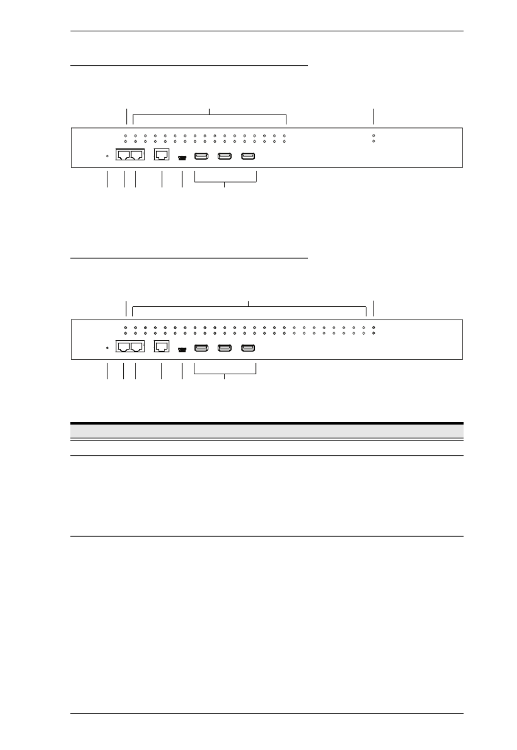
SN0132CO / SN0132COD Front View
SN0148CO / SN0148COD Front View
No. Component Description
1 Power LEDs Lights when the unit is powered up and ready to operate.
2 Port LEDs The Port LEDs provide status information about their
corresponding serial ports.
Lights Green: Online – the serial device attached to the port
is powered on and ready.
Flashes Green: Active – data is being transmitted through
the port
3 LAN LEDs Primary and Secondary 10/100/1000 Mbps LAN LEDs.
RED: 10 Mbps
RED + GREEN (ORANGE): 100 Mbps
GREEN: 1000 Mbps
Flashes to indicate that the Serial Console Server is being
accessed over the LAN.
1 2
4 7 8 9
3
5 6
1 2
4 7 8 9
3
5 6

Serial Console Server User Manual
12
4 Reset Switch Note: This switch is recessed and must be pushed with a small
object such as the end of a paper clip, or a ballpoint pen.
Pressing and releasing this switch when the unit is running
performs a system reset.
Pressing and holding this switch in for more than three
seconds when the unit is running resets its configuration to
the factory default settings.
Note: This does not clear User Account information.
See Clear Login Information, page 157, for
information on clearing user account information.
Pressing and holding this switch while powering on the
switch returns the unit to its factory default firmware level,
rather than the firmware version that the switch has been
upgraded to. This allows you to recover from a failed
firmware upgrade and gives you the opportunity to try
upgrading the firmware again.
Note: This operation should only be performed in the event
of a firmware upgrade failure that results in the device
becoming inoperable.
5 PON Port Reserved.
6 Modem Port For dial in connection should the unit be unavailable over the
network. See Serial Console Server Installation, page 27, step
6 for installation details.
7 Local Console
Port
This RJ45 port allows for local administration and access
through a serial terminal connection to a computer. An SA0141
(DTE to DTE) adapter (included in the package) is required for
this connection.
8 Laptop USB
Console Port
This mini-USB port allows a PC or laptop to be connected for
local access and control. Connect to a PC or laptop to
automatically launch a terminal emulator to access the SN text
menu.
9 USB Ports These three Type A female USB ports can be used to connect
USB devices, such as USB storage devices (pen drive / hard
drive), USB hubs and USB SIM card Reader.
No. Component Description

Serial Console Server User Manual
14
4 Reset Switch Note: This switch is recessed and must be pushed with a small
object such as the end of a paper clip, or a ballpoint pen.
Pressing and releasing this switch when the unit is running
performs a system reset.
Pressing and holding this switch in for more than three
seconds when the unit is running resets its configuration to
the factory default settings.
Note: This does not clear User Account information.
See Clear Login Information, page 157, for
information on clearing user account information.
Pressing and holding this switch while powering on the
switch returns the unit to its factory default firmware level,
rather than the firmware version that the switch has been
upgraded to. This allows you to recover from a failed
firmware upgrade and gives you the opportunity to try
upgrading the firmware again.
Note: This operation should only be performed in the event
of a firmware upgrade failure that results in the device
becoming inoperable.
No. Component Description

Chapter 1. Introduction
15
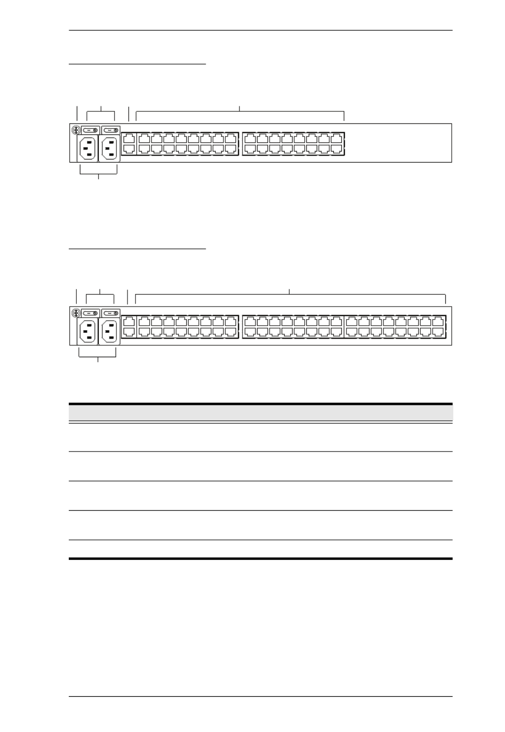
SN0108CO Rear View
SN0116CO Rear View
No. Component Description
1 Grounding
Terminal
The grounding wire that is used to ground the unit attaches
here.
2 Power
Switches
These standard rocker switches power the unit on and off.
3 LAN Ports The cables that connect the unit to the primary and the
backup network interfaces (10/100/1000 Mbps) plug in here.
4 Power Sockets The power cable(s) plugs in here.
5 Serial Ports The Cat 5e cables that connect to the serial devices or
RJ45-to-Serial adapters plug in here.
1
5
2 3
4
1
5
2 3
4

Serial Console Server User Manual
16
SN0108COD Rear View (DC Power)
SN0116COD Rear View (DC Power)
No. Component Description
1 Power
Switches
These standard rocker switches power the unit on and off.
2 LAN Ports The cables that connect the unit to the primary and the
backup network interfaces (10/100/1000 Mbps) plug in here.
3 Serial Ports The Cat 5e cables that connect to the serial devices or
RJ45-to-Serial adapters plug in here.
4 Grounding
Terminal
The grounding wire that is used to ground the unit attaches
here.
5 DC Terminal
Block
The electric leads from your power source connect to this
DC terminal block.
4
31 2
5
31 2
4 5
Chapter 1. Introduction
17
SN0132CO Rear View
SN0148CO Rear View
No. Component Description
1 Grounding
Terminal
The grounding wire that is used to ground the unit attaches
here.
2 Power
Switches
These standard rocker switches power the unit on and off.
3 LAN Ports The cables that connect the unit to the primary and the
backup network interfaces (10/100/1000 Mbps) plug in here.
4 Serial Ports The Cat 5e cables that connect to the serial devices or
RJ45-to-Serial adapters plug in here.
5 Power Sockets The power cable(s) plugs in here.
1 42 3
5
1 42 3
5
Chapter 1. Introduction
19
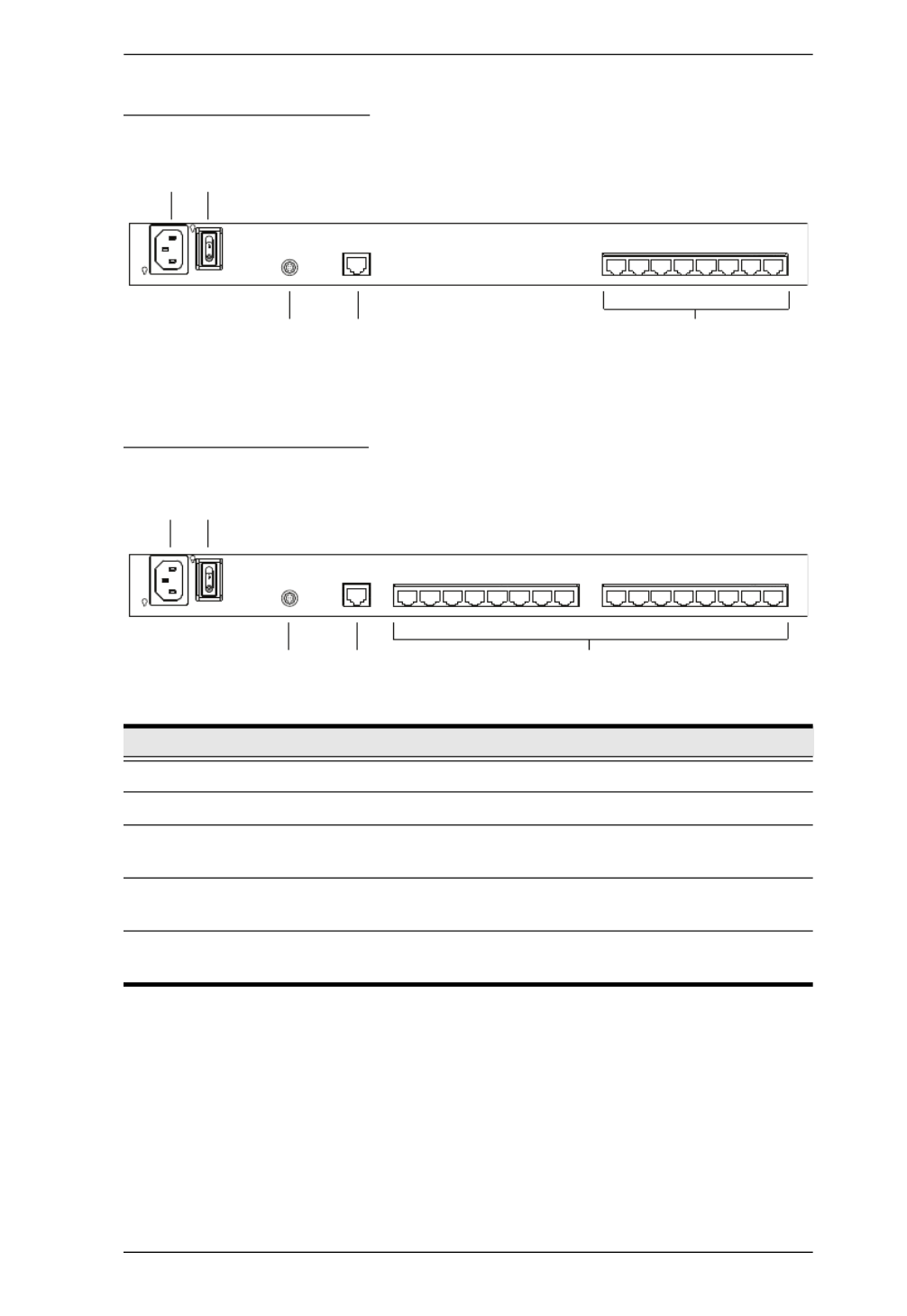
SN9108CO Rear View
SN9116CO Rear View
No. Component Description
1 Power Socket The power cable(s) plugs in here.
2 Power Switch This standard rocker switches power the unit on and off.
3 Grounding
Terminal
The grounding wire that is used to ground the unit attaches
here.
4 LAN Port The cable that connect the unit to the network interface (10/
100/1000 Mbps) plugs in here.
5 Serial Ports The Cat 5e cables that connect to the serial devices or
RJ45-to-Serial adapters plug in here.
1
5
2
3 4
1
5
2
3 4

Serial Console Server User Manual
20
This Page Intentionally Left Blank

Serial Console Server User Manual
22
Note: To ensure adequate ventilation, allow at least 5.1 cm on each side, and
12.7 cm behind the unit for power cord and cable clearance.

Chapter 2. Hardware Setup
23
Rack Mounting
The Serial Console Server can be mounted in a 19" (1U) rack. The mounting
brackets can screw into either the front or the back of the unit so that it can
attach to the front or the back of the rack.
Rack Mounting - Front
To mount the unit at the front of the rack, do the following:
1. Remove the two screws at the front of the unit.
2. Use the M3 x 8 Phillips head hex screws supplied with the rack mount kit
to screw the rack mounting brackets into the front of the unit.
Phillips hex head
M3x8

Chapter 2. Hardware Setup
25
Rack Mounting - Rear
To mount the unit at the rear of the rack, do the following:
1. Remove the two screws at the rear of the unit.
2. Use the M3 x 8 Phillips head hex screws supplied with the rack mounting
kit to screw the rack mounting brackets into the rear of the unit.
3. Position the device in the rack and align the holes in the mounting brackets
with the holes in the rack.
Phillips hex head
M3x8

Chapter 2. Hardware Setup
27
Serial Console Server Installation
SN0108CO / SN0116CO / SN0132CO / SN0148CO Installation
To set up your SN0108CO / SN0116CO / SN0132CO / SN0148CO
installation, refer to the Installation Diagram on page 29. The numbers in the
diagram correspond to the numbers of the instruction steps, below:
1. Use a grounding wire to ground the unit by connecting one end of the wire
to the Serial Console Server’s grounding terminal (located on the back
panel), and the other end of the wire to a suitable grounded object.
Note: Do not omit this step. Proper grounding helps to prevent damage to
the unit from surges or static electricity.
2. For each server or serial device with a DB-9 connector, connect a Cisco
Console Cable or a Cat 5e cable with RJ-45-to-DB-9(F) adapter between
its serial port and any available RJ-45 port on the Serial Console Server’s
rear panel.
Note: Refer to DB-9/DB-25 Interface on page 159 for pin assignments.
3. Connect a Cat 5e cable between a Cisco Network Switch (or any
compatible network switch) and any available RJ-45 port on the Serial
Console Server’s rear panel.
Note: For a compatible network switch, please make sure the RJ-45 port
pin definition of the target device matches the Serial Console Server.
4. Connect the Serial Console Server to the network by connecting both the
primary and backup LAN ports, located on the unit’s rear panel, to the
network with Cat 5e cables.
5. (Optional) If you choose to install a serial modem for OOB operation,
connect a Cisco Console Cable to a null modem adapter. Plug the DB-9
connector into the Modem and the RJ-45 connector into the Modem Port
on the Serial Console Server’s front panel.
6. (Optional) Connect a Cat 5e cable between an ATEN PDU and the PON
Port on the Serial Console Server’s front panel for power management.
7. (Optional) If you wish to use a console terminal connection, use a Cisco
Console Cable to connect between the Serial Console Server’s Local

Serial Console Server User Manual
28
Console Port on the front panel and the DB-9 connector of a console
terminal (or a computer).
For the console terminal or computer without DB-9 connector, you can use
a Cat 5e cable with UC232B to connect between the Local Console Port
and the USB port of the console terminal (or the computer).
Note: The UC232B USB to RJ-45 (RS-232) Console Adapter is sold
separately. Contact you ATEN dealer for product information.
8. (Optional) If you are using a laptop USB console to control the Serial
Console Server locally, use the laptop USB console cable included in the
package to connect the laptop to the LUC port on the Serial Console
Server’s front panel.
9. (Optional) If you are using USB devices (such as USB storage devices)
with your Serial Console Server, connect them to these three Type A
female USB ports.
10. For AC models: Use the AC power cord provided with this package to
connect the SN0108CO/SN0116CO/SN0132CO/SN0148CO's Power
Socket to an AC power source. For DC models: Connect the DC power
source to the SN0108COD/SN0116COD/SN0132COD/SN0148COD's
DC terminal block.
11. Turn on the power switch.

Serial Console Server User Manual
30
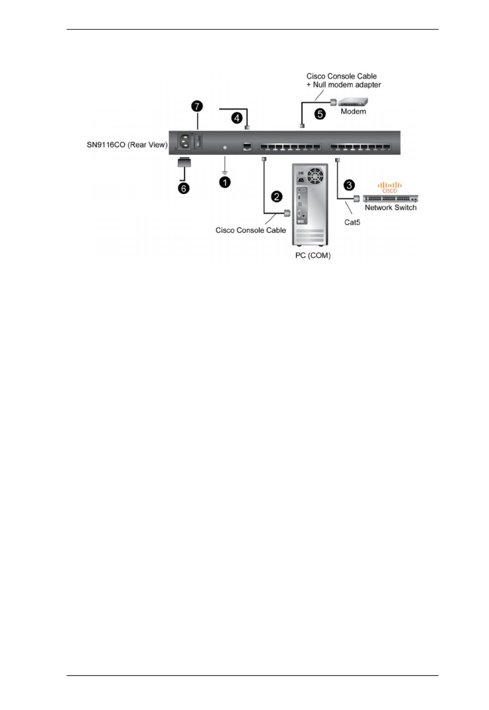
SN9108CO / SN9116CO Installation
To set up your SN9108CO / SN9116CO installation, refer to the Installation
Diagram on page 31. The numbers in the diagram correspond to the numbers
of the instruction steps, below:
1. Use a grounding wire to ground the unit by connecting one end of the wire
to the Serial Console Server’s grounding terminal (located on the back
panel), and the other end of the wire to a suitable grounded object.
Note: Do not omit this step. Proper grounding helps to prevent damage to
the unit from surges or static electricity.
2. For each server or serial device with a DB-9 connector, connect a Cisco
Console Cable or a Cat 5e cable with RJ-45-to-DB-9(F) adapter between
its serial port and any available RJ-45 port on the Serial Console Server’s
rear panel.
Note: Refer to DB-9/DB-25 Interface on page 159 for pin assignments.
3. Connect a Cat 5e cable between a Cisco Network Switch (or any
compatible network switch) and any available RJ-45 port on the Serial
Console Server’s rear panel.
Note: For a compatible network switch, please make sure the RJ-45 port
pin definition of the target device matches the Serial Console Server.
4. Connect the Serial Console Server to the network by connecting the LAN
port to the network with Cat 5e cables.
5. (Optional) If you choose to install a serial modem for OOB operation,
connect a Cisco Console Cable to a null modem adapter. Plug the DB-9
connector into the Modem and the RJ-45 connector into any available RJ-
45 port on the Serial Console Server’s front panel.
6. For AC models: Use the AC power cord provided with this package to
connect the SN9108CO/SN9116CO's Power Socket to an AC power
source.
7. Turn on the power switch.
Chapter 2. Hardware Setup
31
SN9108CO / SN9116CO Installation Diagram

Serial Console Server User Manual
32
This Page Intentionally Left Blank

33
Chapter 3
Super Administrator Setup
Overview
This chapter discusses the administrative procedures that the Super
Administrator performs to get the Serial Console Server set up for the first
time.
First Time Setup
Once the Serial Console Server has been cabled up, the Super Administrator
needs to set up the unit for operation. This involves setting the network
parameters, and changing the default Super Administrator login. The most
convenient way to do this for the first time is from a local console (local VT
console or a local computer running terminal application software, such as
Microsoft HyperTerminal), or a Laptop USB Console (LUC) running the
SNViewerUSB application (SN0108CO / SN0116CO / SN0132CO /
SN0148CO only). Setup can also be done remotely over the Web via the GUI
using the unit’s IP address.
Note: For remote methods of setting up the network, see IP Address
Determination, page 150.
Local Login
You can log in locally from a computer or laptop (SN0108CO / SN0116CO /
SN0132CO / SN0148CO only) connected directly to the Serial Console Server
(see Serial Console Server Installation, page 27). There are two methods for
logging in locally SNViewerUSB and HyperTerminal.
The local login Main Menu is the text based equivalent of the browser based
configuration and control functions described throughout this manual. You can
reference the detailed information provided for the web browser version
(Browser Login, page 37) as you work your way through the sub-menus to
configure the settings discussed in this chapter.
Serial Console Server User Manual
34
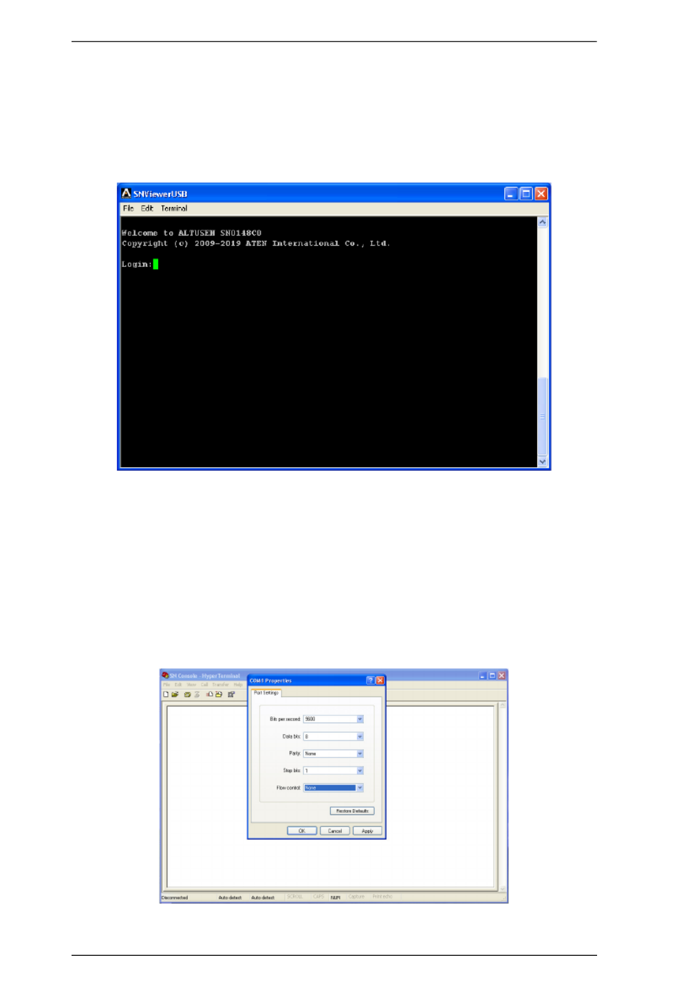
Laptop USB Console (LUC) Login - SNViewerUSB
The SNViewerUSB application appears automatically when a Laptop USB
Console (LUC) connection (SN0108CO / SN0116CO / SN0132CO /
SN0148CO only) has been established, and you will be prompted to log in, as
shown here:
Since this is the first time you are logging in, use the default Username:
administrator; and the default Password: password.
Console Login - HyperTerminal
Once a physical connection from a computer to the Serial Console Server has
been made you can establish a HyperTerminal session using the instructions
below.
1. Open HyperTerminal, and configure the port settings for the COM1 port:

Chapter 3. Super Administrator Setup
39
Changing the Super Administrator Login
To change the default Super Administrator Username and Password, do the
following:
1. At the top of the screen, click the User Management tab.
The User Management page has a list of Users and Groups in the Sidebar
at the left, and a more detailed list of users – with more information about
them – in the large central panel. Since this is the first time the page is
being accessed, only the Super Administrator appears:
2. Click on the account in the left panel or select it in the central panel, then
click Modify (at the bottom of the page.)
The User Information page appears:
3. Change the Username and Password to something unique.

Serial Console Server User Manual
40
4. Enter the password again in the Confirm Password field to confirm it is
correct.
5. Click Save (located at the bottom of the page).
6. When the dialog box informing you that the change completed
successfully appears, Click OK.

41
Chapter 4
The User Interface
Overview
Once you have successfully logged in, the Serial Console Server’s Main Page
appears. The look of the page varies slightly, depending on which method you
used to log in. Each of the interfaces is described in the sections that follow.
Access
The Serial Console Server can be accessed from a local console (locally
connected computer or laptop) running terminal application software (such as
Microsoft HyperTerminal) or the SNViewerUSB application; or from a remote
computer using Telnet (SSH), PuTTY, or web-based browser (see First Time
Setup, page 33 for details).
No matter which access method you choose, the Serial Console Server’s
authentication procedure requires you to submit a valid username and
password. If you supply invalid login information, the authentication routine
will return an Invalid Username or Password, or Login Failed message. If you
see this type of message, log in again with a correct username and password.
Note: If the number of invalid login attempts exceeds a specified amount, a
timeout period is invoked. You must wait until the timeout period
expires before you can attempt to log in again. See Login Failures,
page 119 for further details.

Chapter 4. The User Interface
43
Remote Operation
You can access the Serial Console Server remotely using a web browser, or text
based terminal application such as Telnet or PuTTY, as described below.
Web Browser Login
Serial Console Server units can be accessed via an Internet browser running on
any platform. To access the Serial Console Server, do the following:
1. Open the browser and specify the IP address (See Browser Login, page 37
for details) of the Serial Console Server you want to access in the
browser's location bar.
2. When a Security Alert dialog box appears, accept the certificate – it can be
trusted. If a second certificate appears, accept it as well.
Once you accept the certificate(s), the login page appears:
3. Provide your username and password (see Browser Login, page 37), then
click Login to bring up the Web Browser Main Page, described on the
next page.
Serial Console Server User Manual
44
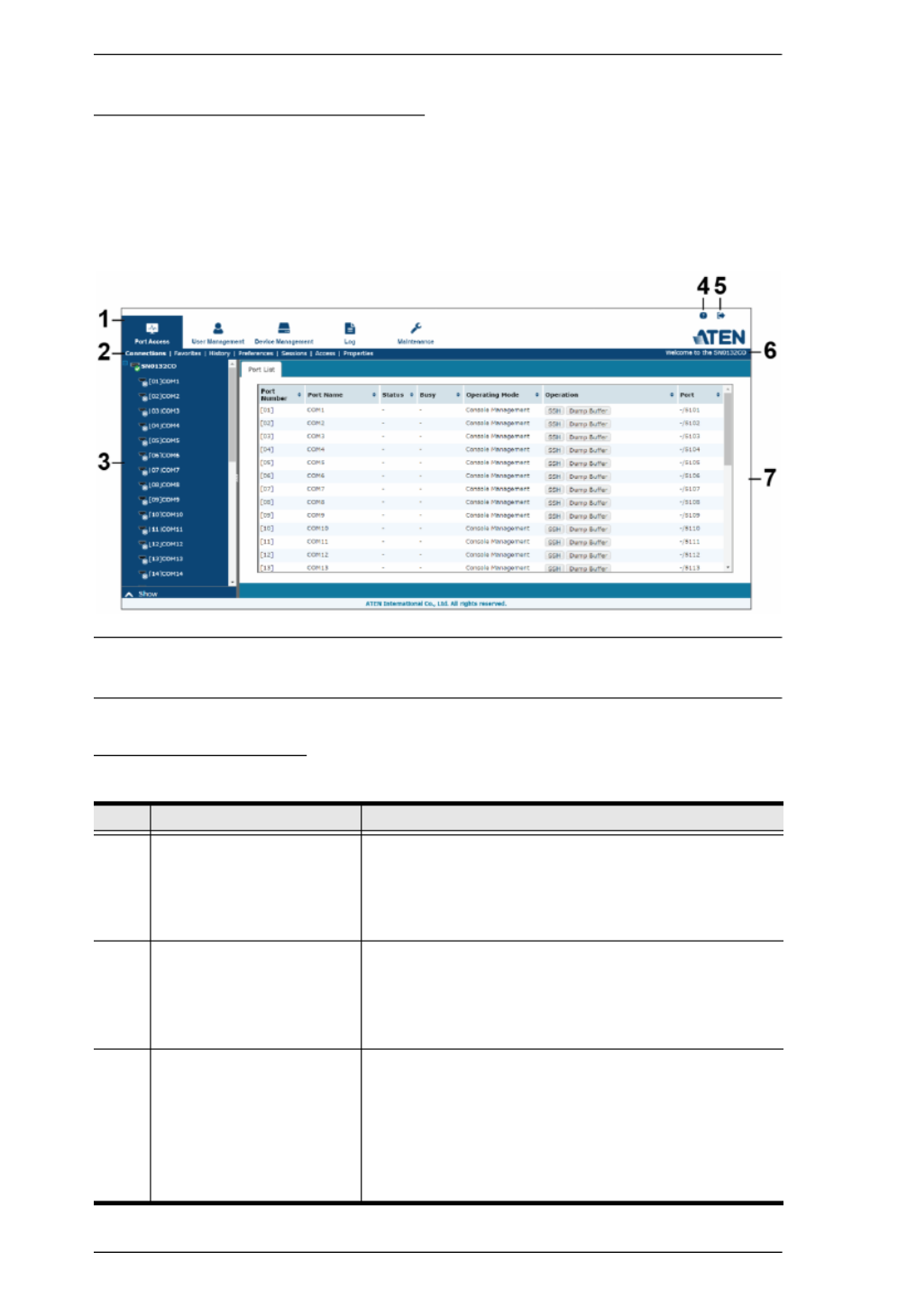
The Web Browser Main Page
To ensure multi-platform operability, access to the Serial Console Server can
be accomplished with most standard web browsers. The chapters following this
one give detailed information about each section of the web browser. Once
users log in and are authenticated (see page 43), the Web Browser Main Page
comes up, with the Port Access page displayed:
Note: The screen depicts a Super Administrator’s page. Depending on a user’s
type and permissions, not all of these elements appear.
Page Components
The web page screen components are described in the table, below:
No. Item Description
1 Tab Bar The tab bar contains the Serial Console Server main
operation categories. The items that appear in the
tab bar are determined by the user’s type, and the
authorization options that were selected when the
user’s account was created.
2 Menu Bar The menu bar contains operational sub-categories
that pertain to the item selected in the tab bar. The
items that appear in the menu bar are determined by
the user’s type, and the authorization options that
were selected when the user’s account was created.
3 Sidebar The Sidebar provides a tree view listing of ports that
relate to the various tab bar and menu bar selections.
Clicking a node in the Sidebar brings up a page with
the details that are relevant to it.
There is a Filter button at the bottom of the Sidebar
that lets you expand or narrow the scope of the ports
that appear in the tree.

Chapter 4. The User Interface
45
4 About About provides information regarding the Serial
Console Server’s current firmware version.
5 Logout Click this button to log out of your Serial Console
Server session.
6 Welcome Message If this function is enabled (see Welcome Message,
page 67), a welcome message displays here.
7 Interactive Display Panel This is your main work area. The screens that appear
here reflect your menu choices and Sidebar node
selection.
No. Item Description

Chapter 4. The User Interface
47
SNViewer
The SNViewer is the main application used to access serial devices via web
browser. The SNViewer opens from the Port Access - Connections page, when
you click the Telnet or SSH button for a serial device (see Telnet/SSH, page 63
for details). When the SNViewer opens there is a Control Panel toolbar that
appears when your mouse moves over it, which allows you to configure your
session, as shown here:
SNViewer Control Panel
The SNViewer provides a Control Panel that is hidden at the upper center of
the screen, and becomes visible when your mouse moves over it. The panel
consists of three rows: an icon row at the top, and two text rows below it:
By default, the upper text row shows the width and height of the window
size. As the mouse pointer moves over the icons in the icon bar, however,
the information in the upper text row changes to describe the icon's
function. In addition, if a message from another user is entered in the
message board, and you have not opened the message board in your
session, the message board window will pop open automatically.
The lower row shows the IP address and port of the device you are
accessing on the left side, and the connection status on the right.

Serial Console Server User Manual
48
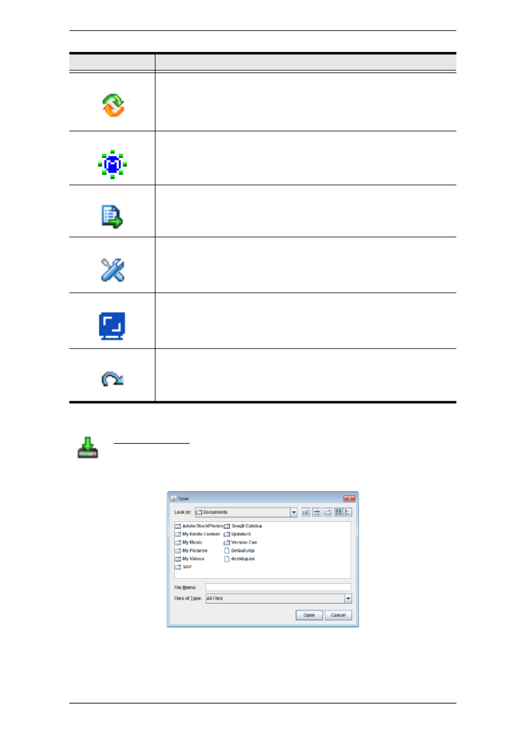
Control Panel Functions
The Control Panel functions are described below and in the following sections:
Icon Function
This is a toggle. Click to make the Control Panel appear Always On
Top
–
i.e., always displays on top of the SNViewer screen. Click
again to have it display in Auto Hide mode
–
allowing it to only
appear when the mouse is moved over it.
Use this to copy the selected text on the screen.
Use this to copy all text that is displayed on the screen.
Use this to paste the copied text.
Use this icon to toggle Logging on / Logging off. This starts a log file
of characters sent from the serial device to the SNViewer. You must
first create and import a text based log file (See Terminal Settings,
Others - Log File, page 53).
Use this to browse for data files to import (see Data Import,
page 49).
Use this to change the page encoding (see Encode, page 50).
Use this icon to enable broadcasting. Broadcasting allows you to
access and make changes on a single port and the same changes
will be made across all Broadcast Ports. Before using the
broadcast function, set the Broadcast Timeout and Broadcast Ports
(see Preferences, page 66 for details).
For broadcasting to work, you must first access a port set as a
Broadcast Port and then click the Broadcast icon on the control
panel.
Click to send a Break command.
Chapter 4. The User Interface
49
Data Import
The Data Import page opens a standard browse menu to import data
files, as shown below:
Use this to reset the terminal to its default settings.
Click to bring up the Message Board (see The Message Board,
page 50).
Click to open a window and create a list of custom text macros (see
Macros, page 51).
Use this to change the font, color and other SNViewer settings (see
Terminal Settings, page 52).
Use this button to adjust the width of the SNViewer window.
Click to exit the viewer.
Icon Function

Serial Console Server User Manual
50
Encode
Encoding allows you select which type of encoding you want to use.
Make your selection from the drop down menu and click OK, as
shown below:
The Message Board
The Serial Console Server supports multiple user logins, which may
cause access conflicts. To alleviate the problem, a message board has
been provided, which allows users to communicate with each other:
Message Display Panel
Messages that users post to the board are display in this panel.
Compose Panel
Key in the messages that you want to post to the board in this panel. Click Send
to post the message to the board.
User List Panel
The username and IP address of all the logged in users are listed in this panel.

Serial Console Server User Manual
52
Terminal Settings
The Terminal Settings page allows you make changes to the
appearance of the terminal window, as described below:
Category Description
Font Click Change to configure the SNViewer’s Font settings. You can
change the Font type, Size, and Style. On the right side of the
window you can view an example of the font you have set.
Color Select an color, Color, Option: Foreground Background Cursor Text
color, or Cursor Color, and Click Change to adjust the color settings.
Use the HSL, Swatches, and HSV tabs to make detailed adjustments
and select the colors.
Below the tab is a Preview section you can use to see how the color
change will look.
Click to remove the changes and OK to save the changes; Cancel
exit; or Reset to revert to the default color settings.

Serial Console Server User Manual
56
Operating Mode
For detailed information about the settings in each of the Operating Modes, see
Operating Mode, page 73.
Console Management
Console Management mode is the most common Operating Mode used,
allowing users to establish Telnet or SSH sessions to the Serial Console Server
to manage the serial devices. In this mode users can log in using the web
browser’s built in SNViewer application via Telnet or SSH; remotely via Telnet
or PuTTY; or directly using the HyperTerminal or SNViewerUSB
applications.
For information about configuring Console Management settings, see page 73.
Note: Be sure that the Socket entry specified on the Network page corresponds
to the port that the device listens on. 5001 is the Serial Console Server’s
default setting (see Network, page 100, and Base Socket, page 101).
Real COM Port
This mode is used in conjunction with a virtual COM port driver installed on
the remote user’s local computer. When the Serial Console Server’s COM port
is set to this mode, the device connected to the port appears as if it were a
device directly connected to a COM port on the remote user’s local computer.
This mode is useful with devices such POS terminals, Bar Code Readers, Serial
printers, etc. since it allows you to use software that was written for pure serial
communication applications.
The Serial Console Server comes with Real COM drivers for Windows
systems and TTY drivers for Linux systems.
For information about configuring Real COM Port settings, see page 73.
TCP Server / TCP Client (Serial Tunnel)
TCP (Transmission Control Protocol) provides a reliable transport layer for
transmitting serial data over the TCP protocol via socket programming.
TCP Server (RAW TCP)
In TCP Server (RAW TCP) mode, data transmission is bidirectional. In this
mode, the host computer initiates contact with the Serial Console Server and
requests a connection to its serial port.

Serial Console Server User Manual
62
Connections
The main panel on the Connections page displays the Port List. From here you
can select and connect to the serial devices via the port they are connected to.
Heading Description
Port Number This column represents the physical port that the device is
connected to on the rear of the Serial Console Server.
Port Name This column shows the port name which can be changed from
the Port Access - Properties page (See page 70 for details).
Status This column shows the On or Off status of a device connected to
the port. If no device is connected to the port a “-” will appear.
Busy This column will show Busy when the port is being accessed by
a user through the Serial Console Server.
Operation Mode This column lists the Work Mode that the port is set to for
access. The most common setting is Console Management,
which is set on the Port Access - Properties page, under the
Operation Mode tab (See Operating Mode, page 73 for details).
Note: Console Management is the means of accessing a serial
device for operations on it.
Operation Lists Console Management access methods: Telnet and SSH for
managing a port device. Clicking either one opens the SNViewer
application to manage that serial device (See Telnet/SSH,
page 63, below). Dump Buffer: This button allows you to dump
and view the buffer log of activity conducted on the device. Click
to save the log. (See Save & Copy, page 71 for details).
Port Shows the respective Telnet and SSH Port number configured for
access to the serial device (See Service Ports, page 101 for
details).

Chapter 6. Port Access
63
Telnet/SSH
To access a serial device connected to the Serial Console Server, click the
port’s Telnet or SSH button from the Port Access - Connections page:
The Serial Console Server opens SNViewer to start your session with the serial
device, and a screen similar to the one below appears:
From the SNViewer can you login and perform management activities on the
serial device. For more information on using the SNViewer, see SNViewer,
page 47 for details.
Port Attributes
Clicking a device on the sidebar from the Port Access - Connections page
brings up the Port Attributes page with detailed information about the device
and Power Over the Net™ reboot options, as shown here:
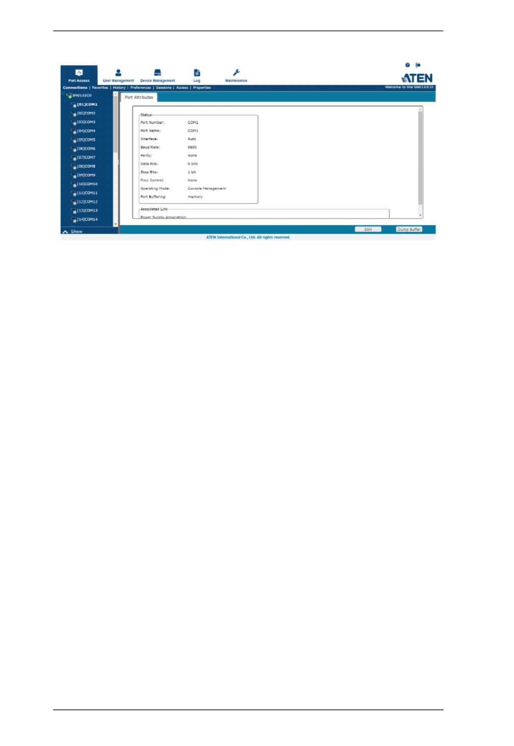
Serial Console Server User Manual
64
From here you can use the Telnet, SSH, and Dump Buffer buttons at the
bottom of the page.
Chapter 6. Port Access
65
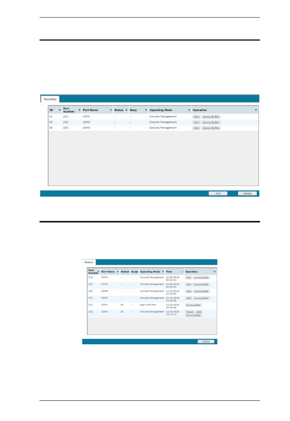
Favorites
The Favorites tab allows you to keep all the connections that you access most
frequently in one convenient place. To add a port to Favorites, right-click on it
from the sidebar and select Add to Favorites, or select a port and click Add.
The layout and functions available on the Favorites tab are exactly the same as
those found on the Port List tab (See Connections, page 62 for details).
History
The History page provides a record of each time that a port was accessed. It
provides quick access to the most recently used ports. You can access a port
shown in the main panel by clicking it’s Telnet or SSH button.
If there are more entries than there is room on the screen, a scroll bar
appears to let you scroll up and down to see the entire record.
To clear the record, click the Delete button at the bottom right of the page.
You can change the sort order by clicking the column headings.

Serial Console Server User Manual
72
Port Buffering
Port Buffering creates a log of activity conducted when a port is accessed. You
can save the log to memory on the Serial Console Server, or to a USB drive. A
USB drive provides more storage space, while the Serial Console Server is
limited to it’s internal memory.
Note: USB drive is only supported on SN01xxCO models.
To enable Port Buffering, from the drop-down menu: select Memory, NFS,
Syslog Server or select a mounted USB drive. Select Disable to disable Port
Buffering. Use the check box to enable/disable Time Stamps.
If you selected a mounted USB drive, addition information is provided:
The Buffer File Name allows you to customize the file name of the log saved
to the USB drive.
For more information on Syslog Server, NFS and mounted USB drive, please
refer to Devices on page 97.
Chapter 6. Port Access
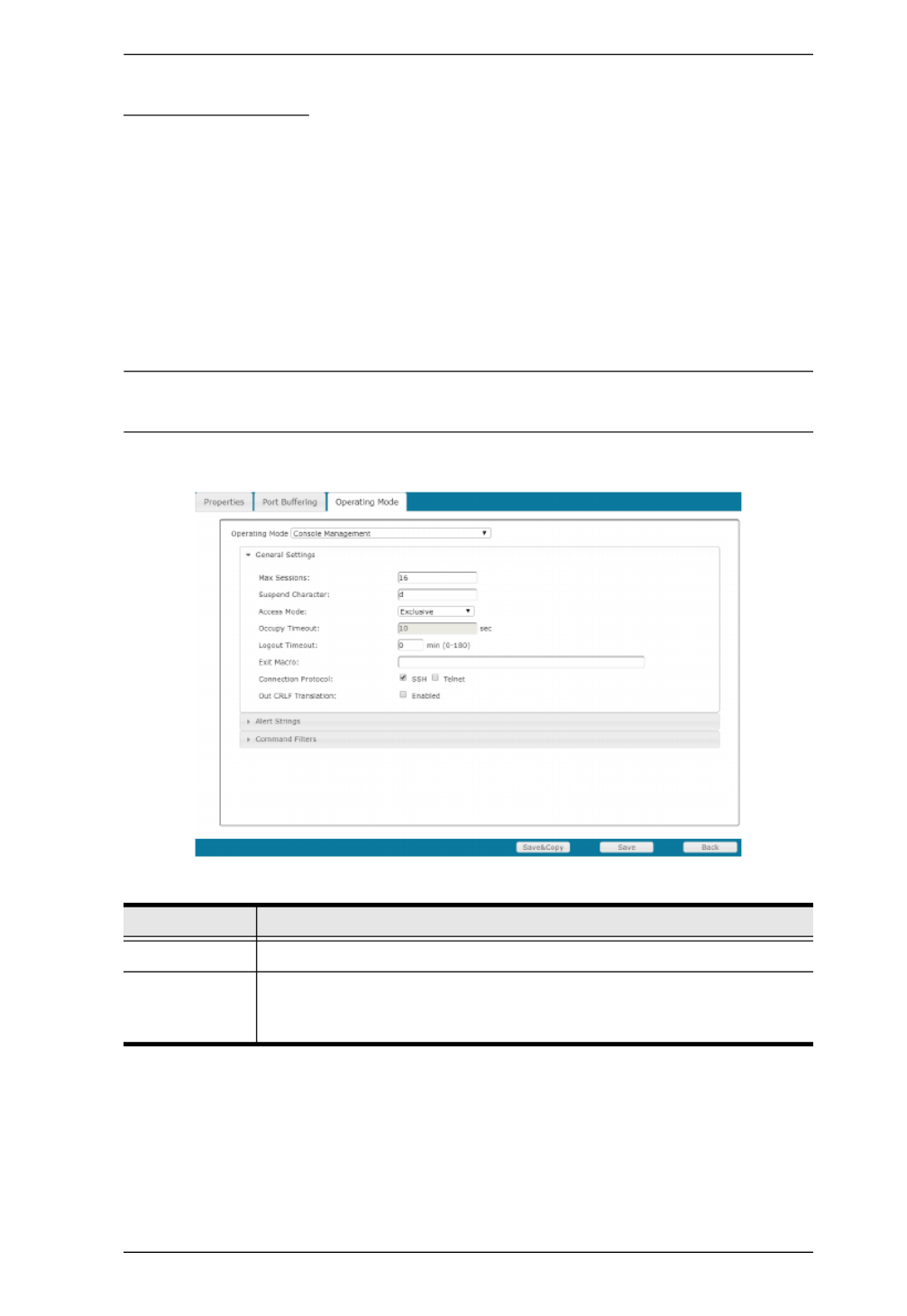
73
Operating Mode
The Operating Mode page allows you to configure settings for access and
management of each port. This determines how each serial device is accessed
via operating modes. For a detailed explanation of each Operating Mode, see
Operating Mode, page 56
Operating Mode – This sets the mode you use to access the port device for
management. The most common setting is Console Management, which
allows for Telnet/SSH sessions from the Port Access - Connections page.
Select the port’s work mode from the drop-down menu.
Note: See Port Operating Modes, page 55, for full details of the different port
operating modes that are available from the drop-down list.
Console Management
Setting Meaning
Max Sessions Set the maximum number of concurrent sessions here.
Suspend
Character
The Suspend character is used to bring up the Suspend Menu in
Telnet sessions. Valid characters are A–Z, except H, I, J, and M -
which may not be used.

Serial Console Server User Manual
74
Alert Strings
The Port Alert Strings dialog box provides a way for you to be informed about
problems that occur on the devices connected to the Serial Console Server's
ports.
Access Mode Defines how the port is to be accessed when multiple users have
logged on, as follows:
Exclusive: The first user to access the port has exclusive control over
the port. No other users can view the port. The Timeout function
does not apply to ports which have this setting.
Occupy: The first user to access the port has control over the port.
However, additional users may view the port. If the user who
controls the port is inactive for longer than the time set in the
Timeout box, port control is transferred to the next user who makes
a change on the system.
Share: Users simultaneously share control over the port. Input from
the users is placed in a queue and executed chronologically.
Occupy
Timeout
If there is no input on this port for the amount of time set with this
function, the port is released for use by another user.
Logout
Timeout
Some applications do not require a user to login and in such a
situation the Occupy Timeout setting will not work since the timer is
set according to the user’s operations. In such a case, use the Logout
Timeout option. With this feature, if there is no user input for the
amount of time set, the user is automatically logged out. Once logged
out, a login is necessary before the device can be accessed again.
Exit Macro Set the Exit Macro here.You can create a macro that will execute
when exiting the serial device.
Connection
Protocol
Use the check boxes to enable/disable SSH and Telnet connection
protocols.
CRLF
Translation
This allows you to select whether to send a Carriage Return and Line
Feed signal (CRLF).
Setting Meaning

Chapter 6. Port Access
75
When a device has a problem – such as a critical error that requires a reboot, or
an SNMP Trap event has been triggered – debug messages can be sent through
its serial port to the Serial Console Server’s COM port.
When the Serial Console Server receives such a message, it can send an SNMP
Trap alert and/or an email to inform the user specified here of the problem. You
can specify up to 10 types of alerts.
After setting up this page, whenever one of the specified alerts is generated,
you will be informed of its occurrence.
Command Filters
On this page you can specify up to 16 command filters.
Real COM Port
Check Enable to encrypt all data being transfered through the session.

Chapter 6. Port Access
77
TCP Client
Setting Meaning
Secure Check Enable to encrypt all data being transfered through the
session.
Destination
Host / Port
Key-in the IP address and service port of Destination Host or another
Serial Console Server (TCP Server) to create a serial tunnel for
transmitting the data by between. The Serial Console Server can
send data to up to 16 host computers simultaneously.

Chapter 6. Port Access
79
Console Management Direct
Setting Meaning
Max Sessions Set the maximum number of concurrent sessions here.
Suspend
Character
The Suspend character is used to bring up the Suspend Menu in
Telnet sessions. Valid characters are A–Z, except H, I, J, and M -
which may not be used.
Access Mode Defines how the port is to be accessed when multiple users have
logged on, as follows:
Exclusive: The first user to access the port has exclusive control over
the port. No other users can view the port. The Timeout function
does not apply to ports which have this setting.
Occupy: The first user to access the port has control over the port.
However, additional users may view the port. If the user who
controls the port is inactive for longer than the time set in the
Timeout box, port control is transferred to the next user who makes
a change on the system.
Share: Users simultaneously share control over the port. Input from
the users is placed in a queue and executed chronologically.
Occupy
Timeout
If there is no input on this port for the amount of time set with this
function, the port is released for use by another user.
Logout
Timeout
Some applications do not require a user to login and in such a
situation the Occupy Timeout setting will not work since the timer is
set according to the user’s operations. In such a case, use the Logout
Timeout option. With this feature, if there is no user input for the
amount of time set, the user is automatically logged out. Once logged
out, a login is necessary before the device can be accessed again.
Exit Macro Set the Exit Macro here.You can create a macro that will execute
when exiting the serial device.
Connection
Protocol
Use the check boxes to enable/disable SSH and Telnet connection
protocols.

Serial Console Server User Manual
82
Users
The Serial Console Server supports three user types, as shown in the table
bellow:
Adding Users
To add a user, and assign user permissions, do the following:
1. Select Users in the Sidebar.
2. Click Add at the bottom of the main panel. The User notebook opens, with
the User tab selected:
User Type Role
Super Administrator Access and manage ports and devices. Manage Users, and
Groups. Configure the overall installation. Configure
personal working environment.
Administrator Access and manage authorized ports and devices. Manage
Users and Groups. Configure personal working environment.
User Access authorized ports and devices. Manage authorized
ports and devices; configure personal working environment.
Note: Users who have been given permission to do so, may
also manage other users.

Chapter 7. User Management
83
3. Enter the required information in the appropriate fields. A description of
each of the fields is given in the table below:
Field Description
Username From 1 to16 characters are allowed depending on the
Account Policy settings. See Account Policy, page 123.
Password From 0 to16 characters are allowed depending on the
Account Policy settings. See Account Policy, page 123.
Confirm Password To be sure there is no mistake in the password, you are
asked to enter it again. The two entries must match.
Description Additional information about the user that you may wish to
include.
Role There are three categories: Super Administrator,
Administrator and User. There is no limitation on the number
of accounts that can be created in each category.
The Super Administrator is responsible for the overall
installation configuration and maintenance; user
management; and device and port assignments. The
Super Administrator’s permissions are automatically
assigned by the system and cannot be altered.
The Administrators default permissions include everything
except Device Admin and , but the User Admin
permissions can be altered for each Administrator by
checking or unchecking any of the permissions
checkboxes.
The Users default permissions include PDU User and
Broadcast User, but the permissions can be altered for
each User by checking or unchecking any of the
permissions checkboxes.
Permissions
Enabling Device Admin allows a user to configure and
control the settings for overall Serial Console Server
operations (see Device Management, page 97).
Enabling User Admin allows a user to create, modify, and
delete user and group accounts.
Enabling Maintenance Admin allows a user to perform all
the Maintenance operations available under the
Maintenance tab (see Maintenance, page 131).
Enabling Logs Admin allows a user to access the system
log (see Log, page 127).
Enabling PDU User allows users to configure Power Over
the Net™ devices
Enabling Broadcast User allows the use of Broadcasting
Enabling View Only User limits users to only being able to
view the display of connected devices. They cannot
control port access, nor can they input any keyboard or
mouse signals to the devices they view.

Chapter 7. User Management
85
7. Click Users in the Sidebar to return to the main screen. The new user
appears in the Sidebar list and in the main panel, as well.
The Sidebar Users list can expand and collapse. If the list is expanded,
click the minus symbol ( – ) next to the Users icon to collapse it; if it is
collapsed there is a plus symbol ( + ) next to the icon. Click the plus
symbol to expand it.
The icon for super administrators has two black bands; the icon for
administrators has one red band.
The large main panel shows the user’s name; the description that was
given when the account was created; and whether the account is
currently active or has been disabled.
Modifying User Accounts
To modify a user account, do the following:
1. In the Sidebar User list, click the user’s name
– or –
In the main panel, select the user’s name
2. Click Modify.
3. In the User page that comes up, make your changes, then click Save.
Note: The User page is discussed on page 82; the Groups page is
discussed on page 89, the Devices page is discussed on page 94.
Deleting User Accounts
To delete a user account do the following:
1. In the main panel, select the user’s name.
2. Click Delete.
3. Click OK.

Serial Console Server User Manual
86
Groups
Groups allow administrators to easily and efficiently manage users and
devices. Since device access rights apply to anyone who is a member of the
group, administrators need only set them once for the group, instead of having
to set them for each user individually. Multiple groups can be defined to allow
some users access to specific devices, while restricting other users from
accessing them.
Creating Groups
To create a group, do the following:
1. Select Groups on the menu bar.
2. Click Add at the bottom of the main panel. The Group notebook opens,
with the Group tab selected:

Chapter 7. User Management
87
3. Enter the required information in the appropriate fields. A description of
each of the fields is given in the table below:
4. At this point you can assign users to the group by selecting the Members
tab – the Members page is discussed on page 92. You can also assign the
group’s port access rights by selecting the Devices tab – the Devices page
is discussed on page 94.
Note: Optionally, you can skip this step now to add more groups and
assign users to them, and come back to it later.
5. When your selections have been made click Save.
6. When the Operation Succeeded message appears, click OK.
7. Click Group in the Sidebar to return to the main screen. The new group
appears in the Sidebar Group list and in the main panel.
The Sidebar Group list can expand and collapse. If the list is expanded,
click the minus symbol ( – ) next to the Users icon to collapse it; if it is
collapsed there is a plus symbol ( + ) next to the icon. Click the plus
symbol to expand it.
The large main panel shows the group’s name, and the description that
was given when the group was created
Repeat the above procedure to add additional groups.
Note: You must perform Step 7 before attempting to add a new group, or else
the new group you are creating will replace the group you just finished
creating.
Field Description
Group Name A maximum of 16 characters is allowed.
Description Additional information about the user that you may
wish to include. A maximum of 63 characters is
allowed.
Permissions Permissions and restrictions for groups are set by
checking the appropriate boxes. These are the same
permissions as the ones specified for Users. See
Permissions, page 83 for details

Serial Console Server User Manual
88
Modifying Groups
To modify a group, do the following:
1. In the Sidebar Group list, click the group’s name
– or –
In the main panel, select the group’s name.
2. Click Modify.
3. In the Group notebook that comes up, make your changes, then click Save.
Note: The Group page is discussed on page 86; the Members page is
discussed on page 92, The Devices page is discussed on page 94.
Deleting Groups
To delete a group do the following:
1. In the Sidebar, click the Groups icon.
2. In the main panel, select the group’s name.
3. Click Delete.
4. Click OK.
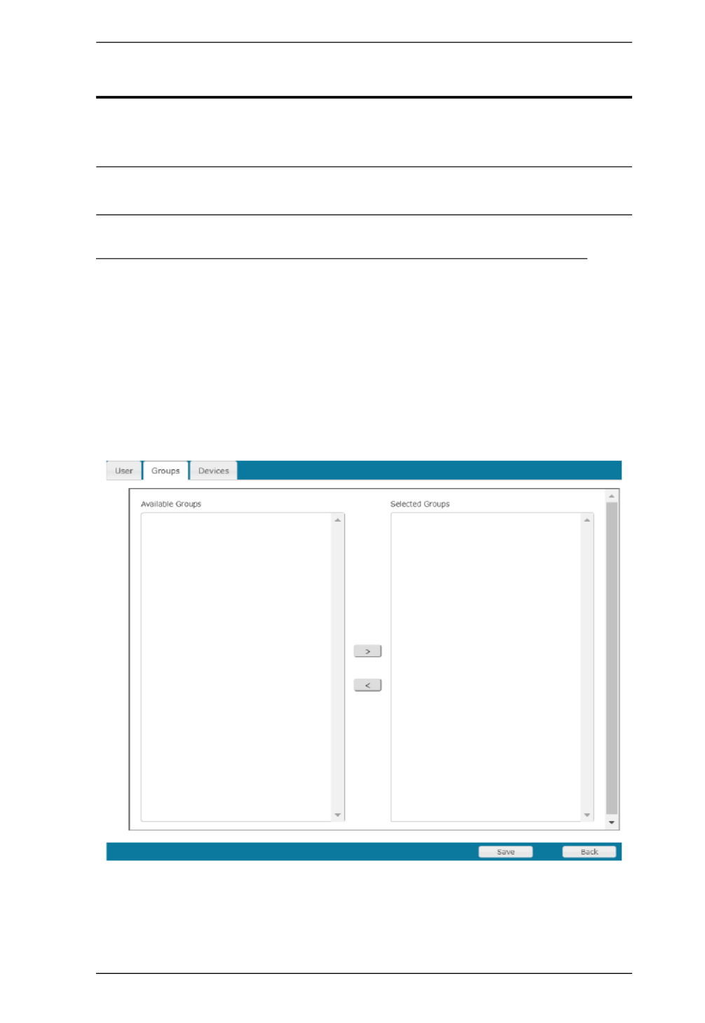
Chapter 7. User Management
89
Users and Groups
There are two ways to manage users and groups: from the Users notebook; and
from the Group notebook.
Note: Before you can assign users to groups, you must first create them.
See Adding Users, page 82 for details.
Assigning Users to a Group From the User’s Notebook
To assign a user to a group from the User’s notebook, do the following:
1. In the Sidebar User list, click the user’s name
– or –
In the main panel, select the user’s name
2. Click Modify.
3. In the User notebook that comes up, select the Groups tab. A screen,
similar to the one below, appears:
4. In the Available column, select the group that you want the user to be in.
5. Click the Right Arrow to put the group’s name into the Selected column.

Serial Console Server User Manual
90
6. Repeat the above for any other groups that you want the user to be in.
7. Click Save when you are done.
Note: If a user has permissions in addition to the ones assigned to the group,
the user keeps those permissions in addition to the group ones.

Chapter 7. User Management
91
Removing Users From a Group From the User’s Notebook
To remove a user from a group from the User’s notebook, do the following:
1. In the Sidebar User list, click the user’s name
– or –
In the main panel, select the user’s name.
2. Click Modify.
3. In the User notebook that comes up, select the Groups tab. A screen,
similar to the one below, appears:
4. In the Selected column, select the group that you want to remove the user
from.
5. Click the Left Arrow to remove the group’s name from the Selected
column. (It goes back into the Available column.)
6. Repeat the above for any other groups that you want to remove the user
from.
7. Click Save when you are done.
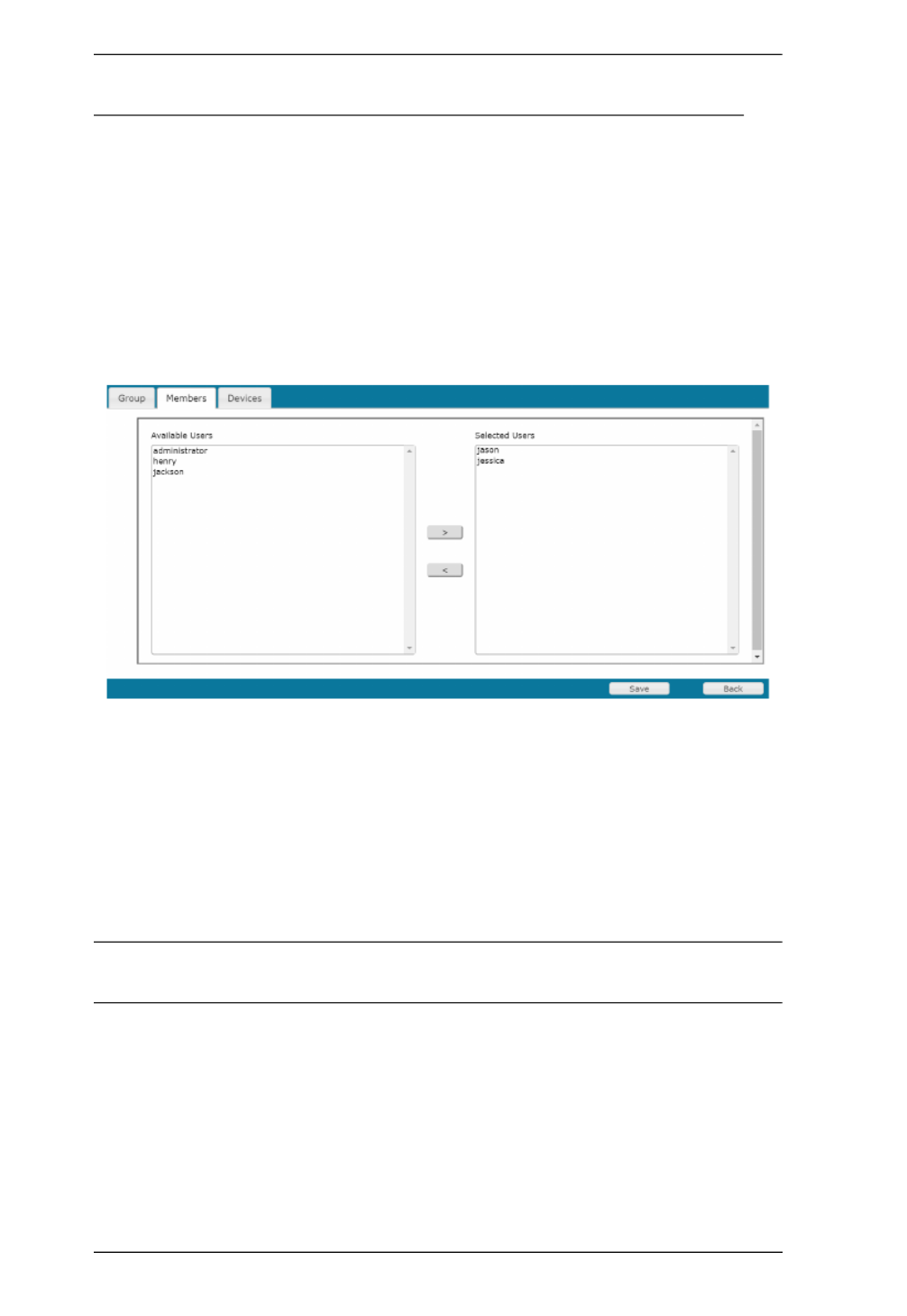
Serial Console Server User Manual
92
Assigning Users to a Group From the Group’s Notebook
To assign a user to a group from the Group notebook, do the following:
1. In the Sidebar Group list, click the group’s name
– or –
In the main panel, select the group’s name.
2. Click Modify.
3. In the Group notebook that comes up, select the Members tab. A screen,
similar to the one below, appears:
4. In the Available column, select the user that you want to be a member of
the group.
5. Click the Right Arrow to put the user’s name into the Selected column.
6. Repeat the above for any other users that you want to be members of the
group.
7. Click Save when you are done.
Note: If a user has permissions in addition to the ones assigned to the group,
the user keeps those permissions in addition to the group ones.

Serial Console Server User Manual
94
Device Assignment
When a user logs in to the Serial Console Server, the interface comes up with
the Port Access page displayed. All the ports that the user is permitted to access
are listed in the Sidebar at the left of the page. Access permissions for those
ports and the devices connected to them are assigned on a port-by-port basis
from the User or Group list on the Sidebar of the User Management page.
Assigning Device Permissions under Settings User
To assign a device permissions to a user from the User’s notebook, do the
following:
1. In the Sidebar User list, click the user’s name
– or –
In the main panel, select the user’s name.
2. Click Modify.
3. In the User notebook that comes up, select the Devices tab. A screen,
similar to the one below, appears:

Chapter 7. User Management
95
4. Make your permission settings for each port according to the information
provided below:
5. When you have finished making your choices, click Save.
6. In the confirmation popup that appears, click OK.
Note: In any of the columns, you can use Shift-Click or Ctrl-Click to select a
group of ports to configure. Clicking to cycle through the choices on
any one of the selected ports causes all of them to cycle in unison.
Name: Each port accessible to the user is listed under the Names
column.
Access: The Access column is where device access rights are set. Click
the radio buttons in the rows that corresponds your choices. The
meanings are described, below:
Full
Access
The user can view the remote screen and can perform
operations on the remote server from his keyboard.
View
Only
The user can only view the remote screen; he cannot
perform any operations on it.
No
Access
No access rights - the Port will not show up on the
User's list on the Main Screen.
Config: The Config column is where a user’s permission to make changes
to a port’s configuration settings are permitted/restricted. A check
mark (
√
) indicates that the user has permission to make
changes to the port’s configuration settings; an empty box means
that the user is denied permission to make configuration changes.
Power Supply: The Power Supply column permits/restricts the configuration and
power operation of ports that have Power Over the Net™ devices
connected to them. A check mark (
√
) indicates that the user has
permission; an empty box means that the user does not have
permission.
Note: Reserved to be used with PG series PDU.

Serial Console Server User Manual
96
Assigning Device Permissions under Group Settings
To assign a device permissions to a Group of users, do the following:
1. In the Sidebar Groups list, click the group’s name
– or –
In the main panel, select the group’s name.
2. Click Modify.
3. In the Groups notebook that comes up, select the Devices tab.
4. The screen that comes up is the same one that appears in the User’s
notebook. The only difference is that whatever settings you make apply to
all members of the group instead of just one individual member.
Make your device assignments according to the information described
under Assigning Device Permissions under User Settings, page 94.

97
Chapter 8
Device Management
Devices
The Device Management page opens with the top level Serial Console Server
selected in the Sidebar, with all its ports nested below, and the Device
Information page displaying in the main panel:
General
The General section of the Device Information page displays and allows you
to set the Device Name and Description and view the Manufacturing (MFG)
information of the Serial Console Server. The Network Interfaces section
provides detailed information about it’s network configurations.
Note: The “MFG Number” (Manufacturing Number) is an internal serial
number used by ATEN’s factory and technical support staff to identify
products. This number does not affect products’ warranty. If your
product requires after-sales services, you may provide the MFG
Number to ATEN’s sales or technical support staff to identify the
product and model number.
The SN0108CO / SN0116CO / SN0132CO / SN0148CO are designed with two
power supplies. The Power Supply Detection section provides information
about the two Serial Console Server’s power supplies.
The icons for Power Supply 1 and Power Supply 2 display in gray when
there is no power to the power supply - they display in blue when power is
present.

Serial Console Server User Manual
98
When the Power Supply Detection function is enabled (there is a check in
the checkbox), when there is only one source of power, the Serial Console
Server will beep to warn you of the problem. The default for this function
is enabled.
If you are at the Local Console you will see a message asking you to
confirm that your intention is to only have one power source. If your
intention is to only have one source of power, there are two ways to stop
the beeping:
1) You can disable power supply warnings by unchecking the
checkbox. Do this if you want to disable this function on a permanent
basis.
2) You can confirm your intention in the dialog box. Do this if you only
want to disable the warning temporarily. With this method, the warning
function will be back in effect after the next system reset.
Mounted Devices
The Mounted Devices section displays information about USB and NFS
storage devices connected for use. When a USB drive is plugged into the front
of the Serial Console Server (SN0108CO / SN0116CO / SN0132CO /
SN0148CO only), or NFS storage locations are set (see NFS Settings below),
they appear here with detailed information about the mounted device.
NFS Settings
NFS (Network File System) allows you to mount storage devices across the
network. You can mount up to 4 devices. Fill in the Source with the storage
devices network location (IP Address or Network Name) including the full
path of the location you want to mount. Next, click Mount to mount the NFS
storage device. The Status column indicates N/A, Mounted, or Unmounted.
Unmounted shows if the storage device is not accessible. If this happens make

Chapter 8. Device Management
99
sure the device is accessible on the network, and check that the Source
information you typed in is correct. Check Auto to auto mount the NFS.
External USB Drive
You can mount up to 3 external USB drives. Click Mount or Unmount to
mount or unmount the drive. The Status column indicates N/A, Mounted, or
Unmounted.
Syslog Settings for Port Logs
You can allow users to store logs on pre-defined Syslog servers.
To activate the function, check the “Enable Syslog” option to enable the
function. When this function is activated, “Syslog server” option will then
become available in the Port Buffering function.
Enter/select the server information in the fields shown in the diagram.

Serial Console Server User Manual
100
Network
The Network page is used to specify the network environment.
Each of the elements on this page is described in the sections that follow.
Note: The Enable Redundant NIC option is only available for SN0108CO /
SN0116CO / SN0132CO / SN0148CO serial console servers.

Chapter 8. Device Management
101
IP Installer
The IP Installer is an external Windows-based utility for assigning IP addresses
to the Serial Console Server.
Click one of the radio buttons to select Enable, View Only, or Disabled for the
IP Installer utility. See IP Installer, page 150, for IP Installer details.
Note: 1. If you select View Only, you will be able to see the Serial Console
Server in the IP Installer’s Device List, but you will not be able to
change the IP address.
2. For security, we strongly recommend that you set this to View Only
or Disable after each use.
Service Ports
As a security measure, if a firewall is being used, the Administrator can specify
the port numbers that the firewall will allow. If a port other than the default is
used, users must specify the port number as part of the IP address when they
log in. If an invalid port number (or no port number) is specified, the Serial
Console Server will not be found. An explanation of the fields is given in the
table below:
Note: 1. Valid entries for all of the Service Ports are from 1–65535.
2. Service ports cannot have the same value. You must set a different
value for each one.
3. If there is no firewall (on an Intranet, for example), it doesn’t matter
what these numbers are set to, since they have no effect.
Field Explanation
HTTP The port number for a browser login. The default is 80.
HTTPS The port number for a secure browser login. The default is 443.
SSH Port The port for SSH access. The default is 22.
Telnet Port The port for Telnet access. The default is 23.
Base Socket The port used to listen for and accept a TCP connection

Serial Console Server User Manual
102
Network Configuration
Redundant NIC*
The SN0108CO / SN0116CO / SN0132CO / SN0148CO are designed
with two network interfaces. If Enable Redundant NIC is enabled (the
default), both interfaces make use of the IP address of network adapter
eth0.
Under this configuration, the second interface is usually inactive. If there
is a network failure on the first interface, the Serial Console Server
automatically switches to the second interface.
Redundant NIC Enabled – Single IP Address for Both Interfaces
To enable the Redundant NIC function, do the following:
1. Click to put a check in the Enable Redundant NIC checkbox.
2. eth0 is selected in the network adapter listbox, and the listbox is
disabled – you cannot configure eth1.
3. Configure the IP and DNS server addresses for eth0 (see the
sections below).
Redundant NIC Not Enabled – Two IP Addresses
If you choose not to enable the Redundant NIC function, the two NICs
can be configured with separate interfaces. Users can log into the
SN0108CO / SN0116CO / SN0132CO / SN0148CO with either IP
address. To set up the Serial Console Server with this configuration, do
the following:
1. If there is a check in the Enable Redundant NIC checkbox, click to
remove it.
2. In the network adapter listbox; select eth0.
3. Configure the IP and DNS server addresses for eth0 (see the
sections below).
4. Drop down the network adapter listbox; select eth1.
5. Configure the IP and DNS server addresses for eth1.
Note: Only available for SN0108CO / SN0116CO / SN0132CO / SN0148CO
devices. To configure SN9108CO / SN9116CO serial console servers,
see IPv4 Settings, page 103,

Chapter 8. Device Management
103
IPv4 Settings
IP Address:
IPv4 is the traditional method of specifying IP addresses. The Serial
Console Server can either have its IP address assigned dynamically
(DHCP), or it can be given a fixed IP address.
For dynamic IP address assignment, select the Obtain IP address
automatically radio button. (This is the default setting.)
To specify a fixed IP address, select the Set IP address manually
radio button and fill in the fields with values appropriate for your
network.
Note: 1. If you choose Obtain IP address automatically, when the unit
starts up it waits to get its IP address from the DHCP server.
If it hasn’t obtained the address after one minute, it
automatically reverts to its factory default IP address
(192.168.0.60 / 61.)
2. If the unit is on a network that uses DHCP to assign network
addresses, and you need to ascertain its IP address, see IP
Address Determination, page 150, for information./
DNS Server
For automatic DNS Server address assignment, select the Obtain
DNS Server address automatically radio button.
To specify the DNS Server address manually, select the Set DNS
server address manually radio button, and fill in the addresses for
the Preferred and Alternate DNS servers with values appropriate
for your network.
Note: Specifying the Alternate DNS Server address is optional.

Serial Console Server User Manual
104
IPv6 Settings
IP Address:
IPv6 is the new (128-bit) format for specifying IP addresses. (See IPv6,
page 152 for further information.) The Serial Console Server can either
have its IPv6 address assigned dynamically (DHCP), or it can be given
a fixed IP address.
For dynamic IP address assignment, select the Obtain IP address
automatically radio button. (This is the default setting.)
To specify a fixed IP address, select the Set IP address manually
radio button and fill in the fields with values appropriate for your
network.
DNS Server
For automatic DNS Server address assignment, select the Obtain
DNS Server address automatically radio button.
To specify the DNS Server address manually, select the Set DNS
server address manually radio button, and fill in the addresses for
the Preferred and Alternate DNS servers with values appropriate
for your network.
Note: Specifying the Alternate DNS Server address is optional.

Chapter 8. Device Management
105
ANMS
The ANMS (Advanced Network Management Settings) page is used to set up
login authentication and authorization management from external sources. It is
organized as a notebook with three tabs – each with a series of related panels,
as described, below:
Event Destination
SMTP Settings
To have the Serial Console Server email reports from the SMTP server to
you, do the following:
1. Enable the Enable report from the following SMTP server, and key in
either the IPv4 address, IPv6 address, or domain name of the SMTP
server.
2. Key in the SMTP port.
3. If your server requires authentication, put a check in the Server requires
authentication checkbox, and key in the appropriate account
information in the Account Name and Password fields.

Serial Console Server User Manual
106
4. Key in the email address of where the report is being sent from in the
From field.
Note: 1. Only one email address is allowed in the From field, and it
cannot exceed 64 Bytes.
2. 1 Byte = 1 English alphanumeric character.
5. Key in the email address (addresses) of where you want the SMTP
reports sent to in the To field.
Note: If you are sending the report to more than one email address,
separate the addresses with a semicolon. The total cannot exceed
256 Bytes.
Log Server
Important transactions that occur on the Serial Console Server, such as
logins and internal status messages, are kept in an automatically generated
log file.
To enable this, put a check in the Enable report from the following Log
Server checkbox.
Specify the MAC address of the computer that the Log Server runs on
in the MAC address field.
Specify the port used by the computer that the Log Server runs on to
listen for log details in the Service Port field. The valid port range is 1–
65535. The default port number is 9001.
Note: The port number must different than the one used for the Program
port.

Chapter 8. Device Management
107
SNMP Server
Up to four SNMP management stations can be specified. If you want to use
SNMP trap notifications, do the following:
1. Check Enable SNMP Trap and key in the Community.
2. Key in the IP address(es) and the service port number(s) of the
computer(s) to be notified of SNMP trap events. The valid port range is
1–65535. The default port number is 162.
Note: Make sure that the port number you specify here matches the port
number used by the SNMP receiver computer.
3. Key in the community value(s) if required for the SNMP version.
To use SNMP V3, do the following:
1. Check Enable SNMP V3.
2. Key in the Community values.
3. The client setting for the authorization protocol should only use SHA
and AES-128 encryption.
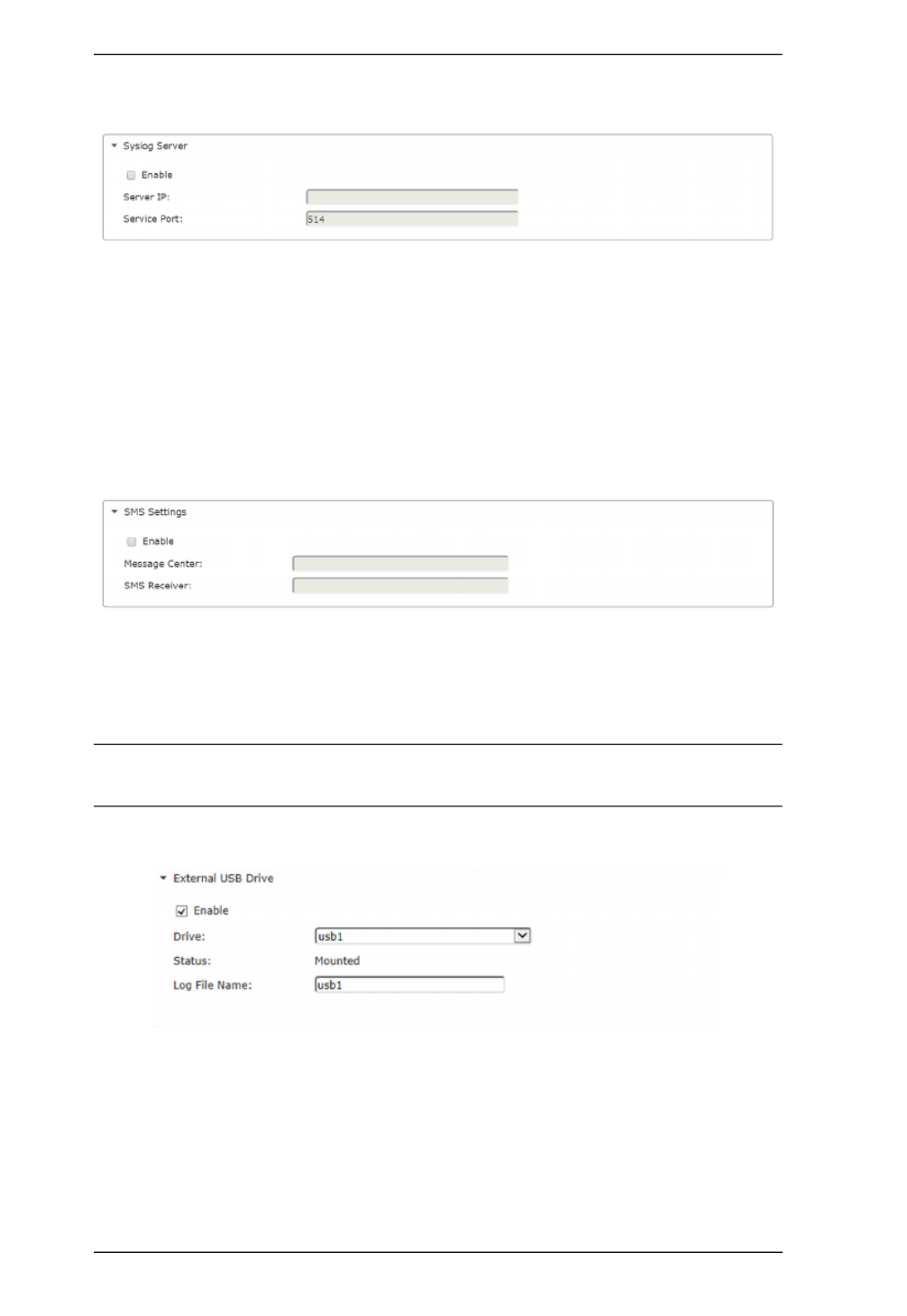
Serial Console Server User Manual
108
Syslog Server
To record all the events that take place on Serial Console Server and write
them to a Syslog server, do the following:
1. Check Enable.
2. Key in either the IPv4 address, IPv6 address, or domain name of the
Syslog server.
3. Key in the port number. The valid port range is 1-65535.
SMS Settings
To receive notifications via SMS, do the following:
1. Check Enable.
2. Enter the telephone numbers for the Message Center and SMS Receiver.
Note: When you have made all your changes, remember to click Save at the
bottom right corner of the page.
External USB Drive
To record all the events that take place on Serial Console Server and write
them to an external USB drive, do the following:
1. Check Enable.
2. Select the drive you wish to write the events to.
3. Key in the file name for the log.
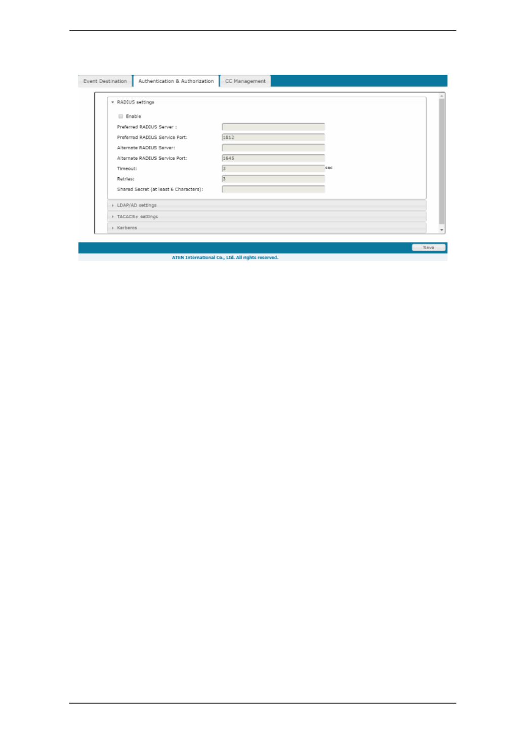
Chapter 8. Device Management
109
Authentication and Authorization
RADIUS Settings
To allow authentication and authorization for the Serial Console Server
through a RADIUS server, do the following:
1. Check Enable.
2. Fill in the IP addresses and service port numbers for the Preferred and
Alternate RADIUS servers. You can use the IPv4 address, the IPv6
address or the domain name in the IP fields.
3. In the Timeout field, set the time in seconds that the Serial Console
Server waits for a RADIUS server reply before it times out.
4. In the Retries field, set the number of allowed RADIUS retries.
5. In the Shared Secret field, key in the character string that you want to
use for authentication between the Serial Console Server and the
RADIUS Server. A minimum of 6 characters is required.
6. On the RADIUS server, Users can be authenticated with any of the
following methods:
Set the entry for the user as su/xxxx
Where xxxx represents the Username given to the user when the
account was created on the Serial Console Server.
Use the same Username on both the RADIUS server and the
Serial Console Server.
Use the same Group name on both the RADIUS server and the
Serial Console Server.
Use the same Username/Group name on both the RADIUS server
and the Serial Console Server.

Serial Console Server User Manual
110
In each case, the user’s access rights are the ones assigned that were
assigned when the User of Group was created on the Serial Console
Server. (See Adding Users, page 82.)
LDAP / AD Settings
To allow authentication and authorization for the Serial Console Server via
LDAP / AD, refer to the information in the table, below:
Item Action
Enable Check the checkbox to enable LDAP, andEnable Enable SSL
checkbox to enable LDAPS authentication and authorization.
LDAP Server IP
and LDAP
Service Port
Fill in the IP address and port number for the LDAP or LDAPS
server.
You can use the IPv4 address, the IPv6 address or the
domain name in the LDAP Server field.
For LDAP, the default port number is 389; for LDAPS, the
default port number is 636.
Alternate LDAP
Server and
Alternate LDAP
Service Port
Fill in the IP address and port number for the alternate LDAP or
LDAPS server.
You can use the IPv4 address, the IPv6 address or the
domain name in the Alternate LDAP Server field.
For an Alternate LDAP Service Port, the default port number
is 389; for an Alternate LDAPS Service Port, the default port
number is 636.
Admin DN Consult the LDAP / LDAPS administrator to ascertain the
appropriate entry for this field. For example, the entry might
look like this:
ou=kn4132,dc=aten,dc=com
Admin Name Key in the LDAP administrator’s username.
Admin Password Key in the LDAP administrator’s password.
Search DN Set the distinguished name of the search base. This is the
domain name where the search starts for user names.

Chapter 8. Device Management
111
On the LDAP / AD server, Users can be authenticated with any of the
following methods:
With MS Active Directory schema.
Note: If this method is used, the LDAP schema for MS Active Directory
must be extended. Without schema – Only the Usernames used on
the Serial Console Server are matched to the names on the LDAP /
LDAPS server. User privileges are the same as the ones configured
on the Serial Console Server.
Without schema – Only Groups in AD are matched. User privileges are the
ones configured for the groups he belongs to on the Serial Console Server.
Without schema – Usernames and Groups in AD are matched. User
privileges are the ones configured for the User and the Groups he belongs
to on the Serial Console Server.
TACACS+ Settings
Enable TACACS+ and enter the following information:
Preferred TACACS+ Server
Preferred TACACS+ Service Port
Shared Secret 1
Alternate TACACS+ Server
Alternate TACACS+ Service Port
Shared Secret 2
Timeout Set the time in seconds that the Serial Console Server waits for
an LDAP or LDAPS server reply before it times out.
Item Action

Serial Console Server User Manual
112
Kerberos
Enable Kerberos and enter the following information:
Kerberos Server
Kerberos Service Port
Kerberos Realm

Chapter 8. Device Management
113
CC Management Settings
To allow authorization for the Serial Console Server through a CC (Control
Center) server, check Enable and fill in the CC Server’s IP address and Service
port in the appropriate fields. You can use the IPv4 address, the IPv6 address
or the domain name in the CC Server IP field.
Note: If this function is enabled, PON devices do not appear in the Sidebar,
even if they are configured on the Serial Console Server. This is because
they are managed via the CC server.

Chapter 8. Device Management
115
SN0108CO / SN0116CO / SN0132CO / SN0148CO

Chapter 8. Device Management
117
Enable Dial Back
When you enable Out of Band Access, the Enable Dial Back, and Enable Dial
Out functions become available, as described in the sections that follow. As an
added security feature, if this function is enabled, the Serial Console Server
disconnects the calls that dial in to it, and dials back to one of the entries
specified in the table below:
Enable Dial Out
For the dial out function, you must establish an account with an Internet
Service Provider, and use a modem to dial up to your ISP account. An
explanation of the Enable Dial Out items is given in the table below:
Item Action
Enable Fixed
Number Dial
Back
If Fixed Number Dial Back is enabled, when there is an incoming call,
the Serial Console Server hangs up the modem and dials back to the
modem whose phone number is specified in the Phone Number field.
Key the phone number of the modem that you want the Serial Console
Server to dial back to in the Phone Number field.
Enable
Flexible Dial
Back
If Flexible Dial Back is enabled, the modem that the Serial Console
Server dials back to doesn’t have to be fixed. It can dial back to any
modem that is convenient for the user, as follows:
1. Key the password that the users must specify in the Password field.
2. When connecting to the Serial Console Server’s modem, users
specify the phone number of the modem that they want the Serial
Console Server to dial back to as their Username, and specify the
password set in the Password field for their password.
Item Action
ISP Settings Specify the telephone number, account name (username), and
password that you use to connect to your ISP.

Chapter 8. Device Management
119
Security
The Security page is divided into 4 main panels, as described in the sections
that follow.
Login Failures
For increased security, the Login Failures section allows administrators to set
policies governing what happens when a user fails to log in successfully.
To set Login Failures, check one of the Login Fail Policy checkboxes. The
meanings of the entries are explained in the table below:
Note: If a Login Fail Policy is not enabled, users can attempt to log in an
unlimited number of times with no restrictions. For security purposes,
we recommend that you enable this function and enable the lockout
policies.
Entry Explanation
Login Fail Policy This determines what happens when a user fails to
log in according to the security parameters that are
set here. When a user exceeds the maximum login
failures, you can set the Serial Console Server to:
Disable User Account
IP Address Locked
The amount of time the policy takes effect is set in
the Lockout Period.
Maximum login Failures This field sets the number of failed attempts a user is
allowed before the Login Fail Policy is activated.
Lockout Period Sets the amount of time the User Account is disabled
or IP Address is Locked before access will be
reactivated.

Serial Console Server User Manual
120
Security Level
For increased security, you can check or uncheck the boxes to High, Medium
- high, Medium or Custom security features.
1. High (Disable all services except: SSHv2, HTTPS(TLS v1.2))
2. Medium-high (Enables SSHv2, redirect HTTP to HTTPS, HTTPS(TLS
v1.2), ICMP)
3. Medium (Enables SSHv2, redirect HTTP to HTTPS, HTTPS(TLS v1.0,
1.1, 1.2), SNMP Agent, ICMP) (Default)
4. Custom: Click to check the following security options you wish to apply:
Enable Telnet service
Enable SNMP Agent service
Enable ICMP service
Enable SSH service (checked by default)
Enable HTTP and redirect to HTTPS (checked by default)
HTTPS SSL/TLS version: Select between “TLS 1.2”, ”TLS 1.0, 1.1,
1.2” (default), and “SSL 3.0, TLS 1.0, 1.1, 1.2”.
Working Mode
For increased security, you can check or uncheck the boxes to enable FIPS
140-2 for cryptographic modules.

Chapter 8. Device Management
121
IP/MAC Filter
IP and MAC Filtering
IP and MAC Filters control access to the Serial Console Server based on
the IP and/or MAC addresses of the client computers attempting to
connect. A maximum of 100 IP filters and 100 MAC filters are allowed. If
any filters have been configured, they appear in the IP Filter and/or MAC
Filter list boxes.
To enable IP and/or MAC filtering, select one of the following radio
buttons:
If the Include button is selected, all the addresses within the filter are
allowed access; all other addresses are denied access.
If the Exclude button is selected, all the addresses within the filter are
denied access; all other addresses are allowed access.
Adding Filters
To add an IP filter, do the following:
1. Click Add. A dialog box appears:
2. Key the IP address you want to filter.
3. After filling in the address, click OK.
4. Repeat these steps for any additional IP addresses you want to filter.

Serial Console Server User Manual
122
To add a MAC filter, do the following:
1. Click Add. A dialog box appears
2. Specify the MAC address in the dialog box, then click OK.
3. Repeat these steps for any additional MAC addresses you want to filter.
IP Filter / MAC Filter Conflict
If there is a conflict between an IP filter and a MAC filter – in other words,
if a computer’s address is allowed by one filter but blocked by the other –
then the blocking filter takes precedence (the computer’s access is
blocked).
Modifying Filters
To modify a filter, select it in the IP Filter or MAC Filter list boxes and
click Modify. The Modify dialog box is similar to the Add dialog box.
When it comes up, simply delete the old address(es) and replace it with the
new one(s).
Deleting Filters
To delete a filter, select it in the IP Filter or MAC Filter list box and click
Delete.

Serial Console Server User Manual
124
Association
The Association tab is currently reserved.

131
Chapter 10
Maintenance
Overview
The Maintenance function is used to upgrade firmware; backup and restore
configuration and account information; and restore default values.
Backup / Restore
When you click on the Maintenance tab, it opens with the Backup/Restore
page. This page gives you the ability to back up the Serial Console Server’s
configuration and user profile information:

Serial Console Server User Manual
132
Backup
To backup the device’s settings do the following:
1. In the Password field, key in a password for the file.
Note: 1. Setting a password is optional. If you do not set one, the file can
be restored without specifying a password.
2. If you do set a password, make a note of it, since you will need it
to be able to restore the file.
2. Click Backup.
3. When the browser asks what you want to do with the file, select Save to
disk; then save it in a convenient location.
Restore
To restore a previous backup, do the following:
1. Click Browse; navigate to the file and select it.
Note: If you renamed the file, you can leave the new name. There is no
need to return it to its original name.
2. If you set a password when you created the file, key it in the Password
field.
3. Select as many of the options that are presented as you wish to restore.
4. Click Restore.
After the file is restored, a message appears to inform you that the
procedure succeeded.

Serial Console Server User Manual
134
Certificates
This page provides information on the Private Certificates:
Private Certificate
When logging in over a secure (SSL) connection, a signed certificate is used to
verify that the user is logging in to the intended site. For enhanced security, the
Private Certificate section allows you to use your own private encryption key
and signed certificate, rather than the default ATEN certificate.
There are two methods for establishing your private certificate: generating a
self-signed certificate; and importing a third-party certificate authority (CA)
signed certificate.
Generating a Self-Signed Certificate
If you wish to create your own self-signed certificate, a free utility –
openssl.exe – is available for download over the web.
Obtaining a CA Signed SSL Server Certificate
For the greatest security, we recommend using a third party certificate
authority (CA) signed certificate. To obtain a third party signed certificate,
go to a CA (Certificate Authority) website to apply for an SSL certificate.
After the CA sends you the certificate and private encryption key, save
them to a convenient location on your computer.
Importing the Private Certificate
To import the private certificate, do the following:

Chapter 10. Maintenance
135
1. Click Import from the bottom of the Private Certificate page, shown here:
2. Click Browse to the right of Certificate Filename; and browse to where
your certificate file is located; and select it.
3. Click Import to complete the procedure.
Note: Clicking Restore Defaults returns the device to using the default ATEN
certificate.

Serial Console Server User Manual
136
Certificate Signing Request
The Certificate Signing Request (CSR) section provides an automated way of
obtaining and installing a CA signed SSL server certificate.
To perform this operation do the following:
1. Click New. The following dialog box appears:
2. Fill in the form – with entries that are valid for your site – according to the
example information in the following table:
Information Example
Country (2 letter code) TW
State or Province Taiwan
Locality Taipei
Organization Your Company, Ltd.
Unit Tech Department
Common Name mycompany.com
Note: This must be the exact domain name of the site
that you want the certificate to be valid for. If the site’s
domain name is www.mycompany.com, and you only
specify mycompany.com, the certificate will not be valid.
Email Address administrator@yourcompany.com

Serial Console Server User Manual
138
This Page Intentionally Left Blank
Produktspezifikationen
| Marke: | ATen |
| Kategorie: | Server |
| Modell: | SN0116CO-AX-U |
Brauchst du Hilfe?
Wenn Sie Hilfe mit ATen SN0116CO-AX-U benötigen, stellen Sie unten eine Frage und andere Benutzer werden Ihnen antworten
Bedienungsanleitung Server ATen

21 August 2024
20 August 2024
20 August 2024
20 August 2024
20 August 2024
19 August 2024
19 August 2024
19 August 2024
18 August 2024
18 August 2024
Bedienungsanleitung Server
- Server Acer
- Server Asus
- Server Gigabyte
- Server HP
- Server Medion
- Server Sony
- Server ZyXEL
- Server Buffalo
- Server Allnet
- Server Linksys
- Server Netgear
- Server Fantec
- Server Technics
- Server Abus
- Server Megasat
- Server Toshiba
- Server Lindy
- Server Dell
- Server Lenovo
- Server Tripp Lite
- Server TRENDnet
- Server Western Digital
- Server AVerMedia
- Server Veritas
- Server Black Box
- Server Supermicro
- Server SilverStone
- Server NEC
- Server Monacor
- Server Seagate
- Server Fujitsu
- Server Maxdata
- Server Revox
- Server Totolink
- Server Conceptronic
- Server D-Link
- Server QNAP
- Server Digitus
- Server LevelOne
- Server APC
- Server Cisco
- Server Freecom
- Server Synology
- Server Kramer
- Server Intellinet
- Server Eaton
- Server Hikvision
- Server FLIR
- Server ELAC
- Server Planet
- Server Asustor
- Server Blackmagic Design
- Server Dane Elec
- Server Digi
- Server Dual Bay
- Server EMC
- Server GeoVision
- Server Ibm
- Server In Win
- Server Iomega
- Server LaCie
- Server Provision ISR
- Server Quantum
- Server Sun
- Server AMX
- Server ACTi
- Server Vimar
- Server Siig
- Server Intel
- Server Moxa
- Server StarTech.com
- Server Smart-AVI
- Server Mobotix
- Server Sonnet
- Server SEH
- Server Gefen
- Server Avocent
- Server Atlantis Land
- Server Hanwha
- Server KanexPro
- Server Axis
- Server Advantech
- Server HGST
- Server Kiloview
- Server B&B Electronics
- Server Extron
- Server Atlona
- Server Rocstor
- Server Raidsonic
- Server G-Technology
- Server Infortrend
- Server Areca
- Server Silex
- Server Promise Technology
- Server Matrox
- Server Origin Storage
- Server Ernitec
- Server EXSYS
- Server Raritan
- Server C2G
- Server Chenbro Micom
- Server Lantronix
- Server IStarUSA
- Server Valcom
- Server TAIDEN
- Server MvixUSA
- Server Opengear
- Server Mr. Signal
- Server NETSCOUT
Neueste Bedienungsanleitung für -Kategorien-
24 November 2024

13 Oktober 2024
12 Oktober 2024
12 Oktober 2024

11 Oktober 2024
11 Oktober 2024

10 Oktober 2024
6 Oktober 2024

4 Oktober 2024
3 Oktober 2024