Adder Link Infinity 101T Bedienungsanleitung
Lesen Sie kostenlos die 📖 deutsche Bedienungsanleitung für Adder Link Infinity 101T (41 Seiten) in der Kategorie Schalter. Dieser Bedienungsanleitung war für 21 Personen hilfreich und wurde von 2 Benutzern mit durchschnittlich 4.5 Sternen bewertet
Seite 1/41

ADDERLink™ INFINITY 101T
User Guide

INSTALLATION
1
CONFIGURATIONOPERATION
FURTHER
INFORMATION
INDEX
Introduction
Welcome 2 ................................................................................................................
Supplied items 3 .......................................................................................................
Optional extras 3 .....................................................................................................
Installation
Connections 4 ..........................................................................................................
Video link 5 .........................................................................................................
Network link 6 ...................................................................................................
USB and power connections 7 .......................................................................
Conguration
Initial conguration ..............................................................................................8
Manual factory reset 8 ......................................................................................
ADDERLink INFINITY browser-based conguration utility ................9
Restoring a backup rmware image ...............................................................10
Performing an upgrade ......................................................................................10
Operation
Status indicators 11 .................................................................................................
Resetting...............................................................................................................11
Further information
Getting assistance ..............................................................................................12
Appendix A - Supported video modes 13 ..........................................................
Appendix B - Conguration pages .................................................................14
Appendix C - Dimensions 21 ................................................................................
Appendix D - Tips for success when networking ALIF units ...................22
Appendix E - Troubleshooting .........................................................................24
Appendix F - Glossary 26 ......................................................................................
Appendix G - Open source licenses 29 ..............................................................
Index
Contents

INSTALLATION
2
CONFIGURATIONOPERATION
FURTHER
INFORMATION
INDEX
Introduction
WELCOME
Thank you for choosing the ADDERLink™ INFINITY (aka ALIF) family of high capacity
digital extenders/switches. By encoding high quality video, audio and Hi-Speed USB data
into Internet Protocol (IP) messages, ALIF units offer exible ways to link peripherals and
systems via standard networks.
This guide covers the ALIF101T unit, a highly compact dongle which can be attached to
its host computer and transfer high quality video (single link DisplayPort™ or HDMI™
according to the chosen model) and Hi-Speed USB signals across your network.
One-to-one conguration
The simplest conguration links one RX unit to a single TX unit, either by a direct link or over much
greater distances via a high speed network.
ALIF and AIM
Where multiple ALIF units are used on a network, we have developed the
ADDERLink INFINITY Management (AIM) server to allow comprehensive and secure
central control of all transmitters, receivers and users.
One-to-many conguration
Using multicast techniques, an unlimited number
of receivers* can receive video and audio data
streams from a single TX unit.
* A maximum of thirteen concurrent USB inputs (via
multiple RX units) are permitted to a single TX unit.
ALIF RX
ALIF RX
ALIF RX
Gigabit
Ethernet
ALIF101T
ALIF RX
ALIF101T
When using an AIM server to congure ALIF units, it is vital that all ALIF units that
you wish to locate and control are set to their factory default settings. Otherwise
they will not be located by the AIM server. If necessary, perform a factory reset on
each ALIF unit.
Notes:
• IfyouareusingoneormoreALIF101Ttransmitterswithinaninstallationmanagedbyan
AIMserver,theAIMservermustberunningrmwareversion4.12orabove.
Please also see Appendix D - Tips for success when networking ALIF units

INSTALLATION
3
CONFIGURATIONOPERATION
FURTHER
INFORMATION
INDEX
SUPPLIED ITEMS
Information wallet
containing:
Four self-adhesive rubber feet
Quick start guide
Safety document
ALIF101T-HDMI unit
OPTIONAL EXTRAS
Country-specic power cords
CAB-IEC-AUS (Australia)
CAB-IEC-EURO (Europe)
CAB-IEC-UK (UnitedKingdom)
CAB-IEC-USA (UnitedStates)
12.5W power adapter
Part number: PSU-IEC-5VDC-2.5A
ALIF101T-DP unit

4
INSTALLATIONCONFIGURATIONOPERATION
FURTHER
INFORMATION
INDEX
Installation
CONNECTIONS
Installation involves linking the ALIF101T unit to various ports on the
host computer, while the ALIF RX unit is attached to your peripherals:
Status
indicators
(page 11)
Black USB plug provides Hi-Speed USB
signals (plus power if the external power
adapter is not present)
Red USB plug provides
power only when the
external power adapter is
not present
DisplayPort
or
HDMI
Ethernet
port
(page 6)
Optional
external power
input
(page 7)
Reset
button
(page 8)
(page 7)
Cable tie
mounting slot
Connector
input
(page 5)

5
INSTALLATIONCONFIGURATIONOPERATION
FURTHER
INFORMATION
INDEX
Video link
Each ALIF101T unit is supplied with either a DisplayPort™or HDMI connector
(model dependant). Video signals at pixel clocks up to 300MHz (equivalent to a
maximum resolution of 2560 x 1600 at 60Hz) are permissible. Two channel digital
audio is also supported via the video connector.
To make a video link
1 Connect the ALIF101T video connector to the DisplayPort™ or HDMI socket of
the host computer:
ALIF101T HDMI model Host
computer
HDMI video
port
ALIF101T DP model Host computer
DisplayPort
connector
Support for audio
The ALIF101T can derive its (digital) audio feed either from the USB connection or from
the video link (i.e. embedded audio within the DisplayPort/HDMI signal). In both cases,
the digital audio is converted to analog as it is transferred to the receiver(s), where it is
output via their 3.5mm jack(s). The two audio sources are controlled from the System
Conguration page of the internal utility (see page 15) as follows:
• When the EnableAudio-1 option is checked, the ALIF101T arranges a bi-directional
audio stream with the host computer via the USB connection.
• When the EnableAudio-2 option is checked, the EDID denition of the DisplayPort
or HDMI connection will be altered to permit a uni-directional audio stream via the
video output. This allows the use of embedded audio, even when the video display itself
does not support audio.
Note:Itispossibleforbothoptionstobeenabledatthesametimewithoutissue.

6
INSTALLATIONCONFIGURATIONOPERATION
FURTHER
INFORMATION
INDEX
Network link
ALIF transmitters and receivers can either be connected directly to each other or via a
high speed network.
A single Gigabit Ethernet port is located on the front panel. For direct links via Ethernet
cable, the length of cable should not exceed 100 metres (328 feet). Network cables
used for connections may be category 5, 5e, 6 or 7 twisted-pair cable. The ALIF101T
unit has an auto-sensing capability on its network interfaces, so for direct point-to-point
connections, no ‘crossover’ Ethernet cable is required.
Please see Appendix D for important tips about networking ALIF units.
To link the ALIF101T unit
1 Connect a CAT 5, 5e, 6, or 7 cable to the Gigabit Ethernet socket on the front panel
of the ALIF101T unit.
2 Connect the other end of the cable either directly to an ALIF receiver or to a Gigabit
Ethernet switch, as appropriate.
3 [For connections via a network] repeat steps 1 and 2 for the other ALIF unit(s).
CAT 5, 5e, 6, or 7 link
either directly from
the other ALIF unit
or from a Gigabit
Ethernet switch

7
INSTALLATIONCONFIGURATIONOPERATION
FURTHER
INFORMATION
INDEX
USB and power connections
The ALIF101T unit is designed to be as exible as possible. It can either operate using
an optional external power adapter (see page 3) or derive all of its power from its
two USB plugs. The main advantage offered by using an external power adapter is that it
allows the ALIF101T unit to be active before the host computer; thus allowing a remote
user to access the host’s initial boot up and access the BIOS menu, when required.
If powered by USB only, then both the black and red USB plugs need to be connected.
If powered by external power adapter, only the black Hi-Speed USB plug needs to be
connected, for signal purposes. Whenever, the external power adapter is attached and
operating, then power will be taken from it rather than the USB plugs. There is no
problem if the red USB plug remains connected while the power adapter is used.
This is summarized as follows:
Power Black Red
adapter USB USB Power sourcing behavior
ûü ü PowertakenfrombothUSBplugs.
ü ü ûPowertakenfrompoweradapteronly.
ü ü ü Powertakenfrompoweradapteronly,unlessitbecomes
unavailable,inwhichcasepowerwillbetakenfromboth
USBplugsafterashortinterruption.
Note:TheUSBplugsdonotoperateasaseamlessfailoverfortheexternalpoweradapter;there
willbeashortinterruptionasoperationswitchesfromonepowersourcetotheother.
Host computer
USB ports
Black USB plug provides
USB signals (plus power if
the external power adapter
is not present)
Red USB plug provides
power only when the
external power adapter is
not present
From the optional
external power
adapter
Support for audio
The ALIF101T can derive its (digital) audio feed either from the USB connection or from
the video link (i.e. embedded audio within the DisplayPort/HDMI signal). In both cases,
the digital audio is converted to analog as it is transferred to the receiver(s), where it is
output via their 3.5mm jack(s). The two audio sources are controlled from the System
Conguration page of the internal utility (see page 15) as follows:
• When the EnableAudio-1 option is checked, the ALIF101T arranges a bi-directional
audio stream with the host computer via the USB connection.
• When the EnableAudio-2 option is checked, the EDID denition of the DisplayPort
or HDMI connection will be altered to permit a uni-directional audio stream via the
video output. This allows the use of embedded audio, even when the video display itself
does not support audio.
Note:Itispossibleforbothoptionstobeenabledatthesametimewithoutissue.

8
INSTALLATIONCONFIGURATIONOPERATION
FURTHER
INFORMATION
INDEX
INITIAL CONFIGURATION
ALIF units are designed to be as exible as possible and this principle extends also to
their conguration.
Direct linking
Where ALIF transmitters and receivers are directly linked to each other, very little
conguration action is required, provided that they have their factory default settings in
place. If the standard settings have been changed in a previous installation, you merely
need to perform a factory reset on each unit.
Networked linking
Where ALIF units are connected via networked links, you can either congure them
individually, or congure them collectively using an AIM server:
• Conguring networked ALIF units individually - You need to specify the
network addresses of the ALIF units so that they can locate each other. This is done by
running the ADDERLink INFINITY browser-based conguration utility on a computer
system linked to the same network as the ALIF units.
• Conguring ALIF units collectively - The ADDERLink INFINITY Management
(AIM) server allows you to congure, control and coordinate any number of ALIF
transmitters and receivers from a single application.
• IfyouareusingoneormoreALIF101Ttransmitterswithinaninstallationmanagedbyan
AIMserver,theAIMservermustberunningrmwareversion4.12orabove.
IMPORTANT: When using AIM to congure ALIF units, it is vital that all units that you
wish to locate and control are set to their factory default settings. Otherwise they
will not be located by the AIM server. If necessary, perform a factory reset on each
ALIF unit.
Manual factory reset
A factory reset returns ALIF101T unit to its default conguration. You can perform
factory resets using the ADDERLink INFINITY browser-based conguration utility or
by using this direct manual method.
To perform a manual factory reset
1 Power on the ALIF101T unit.
2 Use a narrow implement (e.g. a straightened-out paper clip) to press-and-hold
the recessed reset button on the front panel for roughly fteen seconds, until the
indicators turn blue (Note:alternatingred/greenindicationswilloccurduringthefteen
secondperiodwhilethebuttonisstillpressed).
3 Release the reset switch.
The indicators will remain blue for a short while (less than ten seconds) while
ALIF101T unit congures itself and should then change to green if all connections
are correct; or orange if one or more of the video, USB and/or network links are
missing.
NOTE: If you are performing a factory reset and intend to disconnect the power
immediately after the reset, you must wait at least 30 seconds after you have released the
reset button for it to complete the process.
Use a straightened-out paper
clip to press the reset button
for roughly 5 seconds
Please also see Appendix D - Tips for success when networking ALIF units
Conguration
9
INSTALLATIONCONFIGURATIONOPERATION
FURTHER
INFORMATION
INDEX
ADDERLink INFINITY browser-based conguration utility
The browser-based conguration utility within all TX and RX units requires a network
connection between the ALIF101T unit and a computer on the same network. The
conguration utility allows you to perform many important functions. Please see
Appendix B.
To connect a computer to access the conguration utility
1 Connect a CAT 5, 5e, 6, or 7 link cable to the network port on the front panel.
The port automatically congures itself, so no cross-over cable is required (but is
supported if you do use one).
2 Connect the other end of the link cable directly to the network port of your
computer.
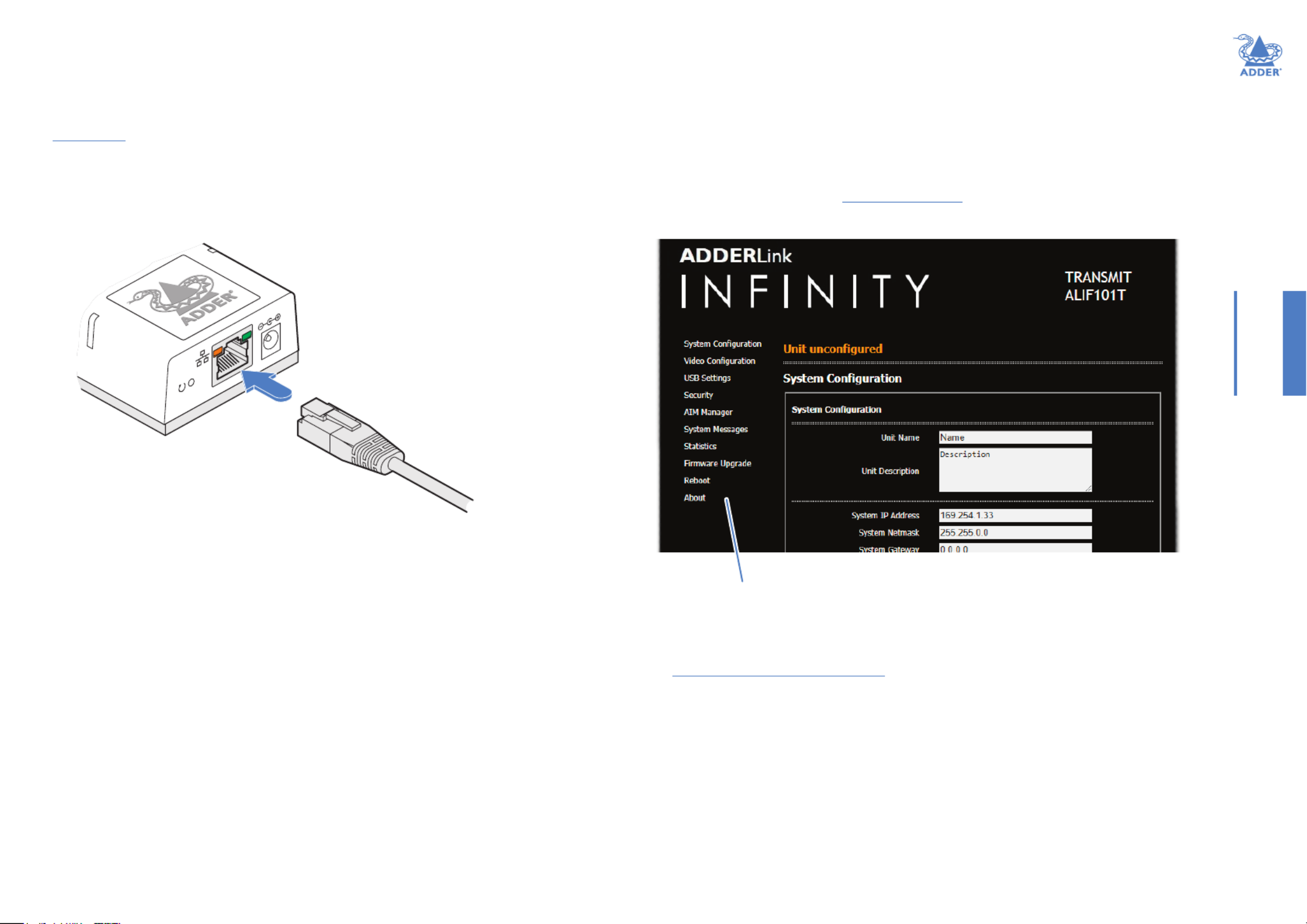
To access the browser-based conguration utility
1 Temporarily connect the ALIF101T unit and your computer, as discussed left.
2 Run a web browser on your computer and enter the IP address of the ALIF101T unit:
169.254.1.33
Note:IftheIPaddressofALIF101Tunithasbeenchangedandisnotknown,providingitis
appropriatetodoso,performa torestorethedefaultaddress.manualfactoryreset
The opening page of the ALIF conguration utility should be displayed:
Use the menu options to choose
the required conguration page
Temporary link
from your computer
to the ALIF101T
network port
You can nd further information about the conguration pages later in this guide:
• Appendix B - Conguration pages

10
INSTALLATIONCONFIGURATIONOPERATION
FURTHER
INFORMATION
INDEX
PERFORMING AN UPGRADE
ALIF101T units are ash upgradeable using the method outlined here. However, for
larger installations we recommend that you use the ADDERLink INFINITY Manager
(AIM) to upgrade multiple ALIF units. When using the method below, the ALIF101T unit
will be upgraded in sequence.
IMPORTANT: Upgrades should be performed equally on transmitters and
receivers at the same time. Mixed rmware operation may cause issues.
WARNING: During the upgrade process, ensure that power is not
interrupted as this may leave ALIF101T unit in an inoperable state.
If the upgrade process is interrupted and fails, it may be necessary to switch to the
backup rmware image in order to regain operation. See left for details.
To upgrade a single ALIF101T unit via the network link
1 Download the latest upgrade le from the Adder Technology website.
2 Temporarily connect the ALIF101T unit and a computer via a network (see
ADDERLink INFINITY browser-based conguration utility section for details).
3 Run a web browser on your computer and enter the IP address of the ALIF101T unit
to be upgraded.
4 Click the Firmware Upgrade link. Within the Firmware Upgrade page, click the Choose
File button. In the subsequent le dialog, locate the downloaded upgrade le - check
that the le is correct for ALIF101T unit being upgraded. The le contains a single
image.
5 Click the Upgrade Now button. A progress bar will be displayed (however, if your
screen is connected to ALIF101T unit being upgraded then video may be interrupted)
and the status indicators on ALIF101T unit will ash while the upgrade is in progress.
6 The indicators should stop ashing after roughly two minutes, after which ALIF101T
unit will automatically reboot itself. The upgrade process is complete.
Finding the latest upgrade les
Firmware les for the ALIF101T units are available from the Support>Product
Downloads section of the Adder Technology website (www.adder.com).
Note:ItispossibletodowngradetheADDERLinkINFINITYrmware.Afterinstallingthe
olderrmware,performafactoryresetoneachADDERLinkINFINITYinordertoclear
thecongurationle.
RESTORING A BACKUP FIRMWARE IMAGE
The ALIF101T unit retains a backup image of the previous rmware version in order to
provide a fallback in case of any issues with the primary image. The backup image has no
video or USB functionality; once invoked, you will need to load an upgrade le using the
web interface or via an ADDERLink INFINITY Manager (AIM) to load a new primary
image - see Performing an upgrade (shown right).
To restore the backup rmware image
1 Power on the ALIF101T unit.
2 Use a narrow implement (e.g. a straightened-out paper clip) to press-and-hold the
recessed reset button for roughly ten seconds until the indicators ash /green red.
3 Release the reset switch.
The ALIF101T unit will switch to the backup rmware image. Once complete,
ALIF101T unit will then continually ash green/red.
4 Perform an upgrade to reinstate a fresh primary rmware image - see right.
Use a straightened-out paper
clip to press the reset button
for roughly 10 seconds

11
INSTALLATIONCONFIGURATIONOPERATION
FURTHER
INFORMATION
INDEX
In operation, many ALIF installations require no intervention once congured. The TX and
RX units take care of all connection control behind the scenes so that you can continue
to work unhindered.
STATUS INDICATORS
The two top panel indicators on the ALIF101T unit provide a useful guide to operation:
Operation
Main status indicators
• Off No power
• Green Operating - Video, USB and network link all present
• Orange Operating - But video, USB and/or network link missing.
• Red (momentarily) Unit is booting up, or
(consistently) Unit has failed, try rebooting.
• Red/green ashing Unit is in backup mode.
• Blue Factory reset has been activated.
• Red/blue ashing Unit is in upgrade mode.
• Fast green ash Unit is in identify mode (see page 15).
Network specic indicators
• Orange Off: No link On: Link established
• Green Off: No link Flashing: Network activity On: Quiescent link
RESETTING
The recessed reset button provides a way to take control of the ALIF101T if normal
operation is affected. You will need a thin implement, such as a straightened out paper
clip to press and hold the button. Depending on when you release the button, one of
three functions will occur:
Required function Release time Indicators
To reboot to the primary rmware version less than 10s red
To boot to the backup rmware version* 10 to 14s / ashgreen red
To restore factory settings and reboot more than 15s blue
*ThebackuprmwareversionhasnovideoorUSBfunctionality.Onceinvoked,youwillneed
toloadanupgradeletorestorenormaloperation-seepage10.
To reset the ALIF101T
1 Power on the ALIF101T unit.
2 Use a narrow implement (e.g. a straightened-out paper clip) to press-and-hold the
recessed reset button. The status indicators will immediately turn :red
Use a straightened-out paper
clip to press the reset button
for roughly 10 seconds
3 Release the reset switch at the appropriate time (see the table above).
NOTE: If you are performing a factory reset and intend to disconnect the
power immediately after the reset, you must wait at least 30 seconds after
you have released the reset button for it to complete the process.
Main status indicators
Network specic
indicators

12
INSTALLATIONCONFIGURATIONOPERATION
FURTHER
INFORMATION
INDEX
This chapter contains a variety of information, including the following:
• Getting assistance - see right
• Appendix A - Supported video modes
• - Conguration pages Appendix B
• Appendix C - Dimensions
• - Tips for success when networking ALIF unitsAppendix D
• - TroubleshootingAppendix E
• Appendix F - Glossary
• Appendix G - Open source licenses
Further information
GETTING ASSISTANCE
If you are still experiencing problems after checking the information contained within this
guide, then please refer to the Support section of our website:
www.adder.com

13
INSTALLATIONCONFIGURATIONOPERATION
FURTHER
INFORMATION
INDEX
APPENDIX A - Supported video modes
The following video modes are supported and can be automatically congured by the
ALIF101T. If a recognized video mode cannot be found, contact Technical Support for help.
Note:Othervideomodesmayalsobesupported.
cvt reduced 1360 x 768 @ 60Hz
vesa 1360 x 768 @ 60Hz
vesa 1366 x 768 @ 60Hz
vesa reduced 1366 x 768 @ 60Hz
vesa 1400 x 1050 @ 60Hz
vesa reduced 1400 x 1050 @ 60Hz
vesa 1440 x 900 @ 60Hz
vesa 1440 x 960 @ 60Hz
cvt reduced 1600 x 900 @ 60Hz
vesa reduced 1600 x 900 @ 60Hz
cvt reduced 1600 x 1200 @ 60Hz
vesa 1600 x 1200 @ 60Hz
vesa 1680 x 1050 @ 60Hz
vesa reduced 1680 x 1050 @ 60Hz
vesa 1920 x 540 @ 60Hz
cvt reduced 1920 x 1080 @ 50Hz
cvt 1920 x 1080 @ 50Hz
vesa 1920 x 1080 @ 60Hz
vesa reduced 1920 x 1200 @ 60Hz
vesa 1920 x 1440 @ 60Hz
vesa 2048 x 768 @ 60Hz
vesa 2048 x 1080 @ 60Hz
vesa 2048 x 1152 @ 60Hz
vesa 2048 x 1536 @ 60Hz
vesa 2048 x 2048 @ 60Hz
vesa 2560 x 1080 @ 60Hz
vesa 2560 x 1080 @ 60Hz
vesa 2560 x 1440 @ 60Hz
vesa 2560 x 1600 @ 60Hz
vesa 2560 x 2048 @ 50Hz
vesa 3440 x 1440 @ 50Hz
sun 1024 x 768 @ 77Hz
sun 1152 x 900 @ 66Hz
sun 1152 x 900 @ 76Hz
sun 1024 x 1024 @ 61Hz
sun 1280 x 1024 @ 67Hz
sun 1280 x 1024 @ 76Hz
cvt reduced 640 x 480 @ 60Hz
vesa 640 x 480 @ 60Hz
vesa 640 x 480 @ 72Hz
vesa 640 x 480 @ 75Hz
ibm 640 x 480 @ 75Hz
vesa 720 x 480 @ 60Hz
vesa 768 x 576 @ 60Hz
vesa 800 x 400 @ 60Hz
cvt reduced 800 x 600 @ 60Hz
vesa 800 x 600 @ 56Hz
vesa 800 x 600 @ 60Hz
vesa 800 x 600 @ 72Hz
vesa 800 x 600 @ 75Hz
cvt 1024 x 600 @ 60Hz
cvt reduced 1024 x 600 @ 60Hz
cvt reduced 1024 x 768 @ 60Hz
vesa 1024 x 768 @ 60Hz
vesa 1024 x 768 @ 70Hz
ibm 1024 x 768 @ 70Hz
vesa 1024 x 768 @ 75Hz
ibm 1024 x 768 @ 75Hz
vesa 1152 x 768 @ 60Hz
cvt reduced 1152 x 864 @ 60Hz
vesa 1152 x 864 @ 70Hz
vesa 1152 x 864 @ 75Hz
cvt 1280 x 720 @ 60Hz
vesa 1280 x 720 @ 60Hz
vesa 1280 x 768 @ 60Hz
vesa reduced 1280 x 786 @ 60Hz
vesa 1280 x 786 @ 75Hz
vesa 1280 x 786 @ 85Hz
vesa 1280 x 800 @ 60Hz
cvt reduced 1280 x 960 @ 60Hz
vesa 1280 x 960 @ 60Hz
cvt reduced 1280 x 1024 @ 60Hz
vesa 1280 x 1024 @ 60Hz
ibm 1280 x 1024 @ 67Hz
vesa 1280 x 1024 @ 75Hz

14
INSTALLATIONCONFIGURATIONOPERATION
FURTHER
INFORMATION
INDEX
APPENDIX B - Conguration pages
This section covers the browser-based conguration utility for the ALIF101T unit. The
pages are titled as follows:
• • System Conguration System Messages
• • Video Conguration Statistics
• • USB Settings Firmware Upgrade
• • Security Reboot
• • AIM Manager About

16
INSTALLATIONCONFIGURATIONOPERATION
FURTHER
INFORMATION
INDEX
Video Conguration Peak bandwidth limiter percentage
The ALIF101T unit will employ a ‘best effort’ strategy in sending video and other data over the IP network.
This means it will use as much of the available network bandwidth as necessary to achieve optimal data quality,
although typically the ALIF101T unit will use considerably less than the maximum available. In order to prevent
the ALIF101T unit from ‘hogging’ too much of the network capacity, you can reduce this setting to place a
tighter limit on the maximum bandwidth permissible to the ALIF101T unit. Range: 0 to 95%.
Background Refresh
The ALIF101T unit sends portions of the video image only when they change. In order to give the best user
experience, the ALIF101T unit also sends the whole video image, at a lower frame rate, in the background. The
Background Refresh parameter controls the rate at which this background image is sent. The default value is
‘every 32 frames’, meaning that a full frame is sent in the background every 32 frames. Reducing this to ‘every
64 frames’ or more will reduce the amount of bandwidth that the ALIF101T unit consumes. On a high-trafc
network this parameter should be reduced in this way to improve overall system performance. Options: every
32 frames, every 64 frames, every 128 frames, every 256 frames or disabled.
Enable Magic Eye
This feature, enabled as standard, aims to reduce the effect of dithering - a technique used by some graphics
cards to improve the perceived quality and color depth of images by diffusing or altering the color of pixels
between video frames. The Magic Eye feature increases the frame rate and eliminates unnecessary network
trafc by ignoring the color dithering where it occurs. If the video source is not noisy or dithered then you
can switch off Magic Eye to enable full color accuracy. Magic Eye mode can remain enabled without penalty for
video that does not have dither or noise.
Use Default DDC and Choose Default DDC
When the UseDefaultDDC option is unticked, ADDERLink INFINITY will use the EDID that is reported by
the monitor connected to the receiver unit. However, if you tick the option, you can then UseDefaultDDC
select from a range of preset video resolutions from the drop down box. Once selected, ChooseDefaultDDC
ALIF101T unit will report itself to prefer this video mode.
Enable Hot Plug Detect on change of display
When this option is ticked, every time the monitor is changed at the receiver unit, hot plug state changes are
sent to the graphics card of the PC attached to the ALIF101T unit as if a screen has just been attached.
Period of Hot Plug Detect signal
This is the length of time that the hot-plug detect signal is de-asserted. The default of 100ms is sufcient for the
majority of HDMI/DP++ graphics cards, however, a small minority may need to be given a longer a period.
Frame skipping percentage
Frame Skipping involves ‘missing out’ video frames between those captured by the ALIF101T unit. For video
sources that update only infrequently or for those that update very frequently but where high delity is not
required, frame skipping is a good strategy for reducing the overall bandwidth consumed by the system. Range: 0
to 100%.
Compression
Determines the (AFZ and AFZ+) compression method used for video transmission. Choices are:
• ‘Pixelperfect’ - only uses pixel perfect AFZ,
• ‘ ’ - guarantees frame rate, builds to pixel perfect, Adaptive
• ‘ ’ - forces the maximum compression, or Smoothestvideo
• ‘ ’ - allows you to choose a xed compression mode: Advanced
• ‘AFZonly(pixelperfect),
• ‘ ,AFZ+Minimumcompression’
• ‘ , orAFZ+Middlecompression’
• ‘AFZ+Maximumcompression’.
To get here
1 Connect your computer to the network port on the front panel.
2 Run a web browser and enter the IP address of the unit. If the address is
unknown, perform a manual factory reset to http://169.254.1.33
3 Click the Video Conguration link.
Produktspezifikationen
| Marke: | Adder |
| Kategorie: | Schalter |
| Modell: | Link Infinity 101T |
| Mitgelieferte Kabel: | DisplayPort, LAN (RJ-45), USB Type-A |
| Produktfarbe: | Schwarz |
| Übertragungstechnik: | Kabelgebunden |
| Material: | Aluminium |
| Anzahl USB 2.0 Anschlüsse: | 2 |
| Betriebstemperatur: | 0 - 50 °C |
| Relative Luftfeuchtigkeit in Betrieb: | 10 - 90 % |
| Verpackungsbreite: | 245 mm |
| Verpackungstiefe: | 55 mm |
| Paketgewicht: | 500 g |
| Netzteil Ausgangsspannung: | 5 V |
| AC-Adapter Ausgangssstrom: | 1 A |
| Warentarifnummer (HS): | 84733080 |
| Typ: | Transmitter |
| Plug & Play: | Ja |
| Temperaturbereich bei Lagerung: | -10 - 60 °C |
| Luftfeuchtigkeit bei Lagerung: | 10 - 90 % |
| PC Audio-Eingang: | Ja |
| Stromstecker-Typ: | Typ A |
| Schnellinstallationsanleitung: | Ja |
| Nachhaltigkeitszertifikate: | CE |
| unterstütze Kabeltypen: | Cat5e |
| PC Audio Ausgang: | Ja |
| Auflösung (maximal, digital): | 2560 x 1600 Pixel |
| Anzahl RJ-45-Anschlüsse: | 1 |
| USB-Port-Typ: | USB Typ-A |
| Gewicht Transmitter: | 200 g |
| Stromverbrauch (Sender) (max.): | 3 W |
| Breite des Senders: | 55 mm |
| Tiefe des Senders: | 25 mm |
| Transmitter lokaler Tastatur-/Maus-Anschlusstyp: | USB |
| Anzahl RJ-45-Anschlüsse (Sender): | 1 |
| Transmitter-Video-Anschlusstyp: | DisplayPort |
Brauchst du Hilfe?
Wenn Sie Hilfe mit Adder Link Infinity 101T benötigen, stellen Sie unten eine Frage und andere Benutzer werden Ihnen antworten
Bedienungsanleitung Schalter Adder

9 Juni 2024
9 Juni 2024
9 Juni 2024
9 Juni 2024
9 Juni 2024
9 Juni 2024
9 Juni 2024
9 Juni 2024
9 Juni 2024
9 Juni 2024
Bedienungsanleitung Schalter
- Schalter Asus
- Schalter Basetech
- Schalter Belkin
- Schalter Hama
- Schalter HP
- Schalter Manhattan
- Schalter Nedis
- Schalter SilverCrest
- Schalter Brennenstuhl
- Schalter Cotech
- Schalter Profile
- Schalter Quigg
- Schalter ZyXEL
- Schalter Bosch
- Schalter Buffalo
- Schalter TechniSat
- Schalter Yamaha
- Schalter Velleman
- Schalter Powerfix
- Schalter Linksys
- Schalter Netgear
- Schalter Schwaiger
- Schalter Alecto
- Schalter EMOS
- Schalter Gira
- Schalter Renkforce
- Schalter Trotec
- Schalter Schneider
- Schalter Worx
- Schalter Pyle
- Schalter Kaiser
- Schalter Jabra
- Schalter One For All
- Schalter Sennheiser
- Schalter Abus
- Schalter Elro
- Schalter Perel
- Schalter Wago
- Schalter Nexa
- Schalter Tork
- Schalter GEV
- Schalter Goobay
- Schalter Lindy
- Schalter Tripp Lite
- Schalter Ansmann
- Schalter Marmitek
- Schalter Honeywell
- Schalter TRENDnet
- Schalter Globaltronics
- Schalter TP-Link
- Schalter Kathrein
- Schalter Flamingo
- Schalter Black Box
- Schalter Techly
- Schalter Theben
- Schalter GAO
- Schalter Kopp
- Schalter Hager
- Schalter Monoprice
- Schalter Monacor
- Schalter Toolcraft
- Schalter Chamberlain
- Schalter Huawei
- Schalter JUNG
- Schalter Ei Electronics
- Schalter Edimax
- Schalter Totolink
- Schalter D-Link
- Schalter QNAP
- Schalter Digitus
- Schalter DataVideo
- Schalter Lancom
- Schalter LevelOne
- Schalter APC
- Schalter Grandstream
- Schalter Grässlin
- Schalter EVE
- Schalter Comet
- Schalter Elektrobock
- Schalter Tenda
- Schalter CyberPower
- Schalter IFM
- Schalter Intertechno
- Schalter Ubiquiti Networks
- Schalter Unify
- Schalter Kramer
- Schalter Intellinet
- Schalter AV:link
- Schalter Hikvision
- Schalter Vemer
- Schalter Planet
- Schalter EnGenius
- Schalter Finder
- Schalter Mikrotik
- Schalter Shimano
- Schalter Homematic IP
- Schalter Heidemann
- Schalter Berker
- Schalter Emerson
- Schalter Intermatic
- Schalter Inverto
- Schalter Mercury
- Schalter Merlin Gerin
- Schalter Paladin
- Schalter Suevia
- Schalter AMX
- Schalter Triax
- Schalter Ubiquiti
- Schalter UPM
- Schalter Vimar
- Schalter Siig
- Schalter Iogear
- Schalter StarTech.com
- Schalter Smart-AVI
- Schalter Shelly
- Schalter Dahua Technology
- Schalter PAC
- Schalter Gefen
- Schalter Avocent
- Schalter Russound
- Schalter Legrand
- Schalter Eltako
- Schalter CYP
- Schalter H-Tronic
- Schalter ATen
- Schalter Noble
- Schalter SmartAVI
- Schalter Rule
- Schalter Kraus & Naimer
- Schalter Chacon
- Schalter Phoenix Contact
- Schalter OSD Audio
- Schalter BZBGear
- Schalter Crestron
- Schalter ORNO
- Schalter Atlona
- Schalter Krone
- Schalter Lightware
- Schalter Roline
- Schalter Wallair
- Schalter Adviti
- Schalter MFA
- Schalter Matrox
- Schalter Blustream
- Schalter Vivolink
- Schalter IB Connect
- Schalter Ernitec
- Schalter Raritan
- Schalter Seuthe
- Schalter Gigahertz Solutions
- Schalter ConnectPro
- Schalter SEADA
- Schalter IPGARD
- Schalter Doepke
- Schalter Micro Connect
- Schalter Epiphan
- Schalter Baco
- Schalter Pizzato Elettrica
- Schalter Upvel
Neueste Bedienungsanleitung für -Kategorien-
3 Dezember 2024
2 Dezember 2024
2 Dezember 2024
2 Dezember 2024
2 Dezember 2024
2 Dezember 2024
2 Dezember 2024
2 Dezember 2024
2 Dezember 2024
2 Dezember 2024