ACTi E61 Bedienungsanleitung
Lesen Sie kostenlos die 📖 deutsche Bedienungsanleitung für ACTi E61 (77 Seiten) in der Kategorie Überwachungskamera. Dieser Bedienungsanleitung war für 26 Personen hilfreich und wurde von 2 Benutzern mit durchschnittlich 4.5 Sternen bewertet
Seite 1/77

www.acti.com
Encoder Firmware V
Encoder Firmware V
Encoder Firmware V
Encoder Firmware VEncoder Firmware V4.06.09
4.06.09
4.06.09
4.06.094.06.09
User’
User’
User’
User’User’s Manual
s Manual
s Manual
s Manuals Manual
1
Firmware User Manual ’s
A1D-500- - V6 3..0 03 AC
201 063/03/

www.acti.com
Firmware User
Firmware User
Firmware User
Firmware UserFirmware User’
’
’
’’s Manual V6.03
s Manual V6.03
s Manual V6.03
s Manual V6.03s Manual V6.03 3
3
3
3 3
.0
.0
.0
.0.0
2
Table of Contents
Recommended PC
Recommended PC
Recommended PC
Recommended PC Recommended PC Specification
Specification
Specification
SpecificationSpecifications
s
s
s s
............................
............................
............................
........................................................
4
4
4
44
Preparation
Preparation
Preparation
Preparation Preparation
.............................................................
.............................................................
.............................................................
..........................................................................................................................
5
5
5
55
Connect the Equipment
Connect the Equipment
Connect the Equipment
Connect the EquipmentConnect the Equipment
5
5
5
55
...........................................................................
...........................................................................
...........................................................................
......................................................................................................................................................
Configure the IP
Configure the IP
Configure the IP
Configure the IPConfigure the IP Addresses
Addresses
Addresses
Addresses Addresses
5
5
5
55
......................................................................
......................................................................
......................................................................
............................................................................................................................................
Access the Camera
Access the Camera
Access the Camera
Access the Camera Access the Camera ...................................................................................
...................................................................................
...................................................................................
......................................................................................................................................................................
9
9
9
99
Live View
Live View
Live View
Live View Live View
...............................................................
...............................................................
...............................................................
..............................................................................................................................
11
11
11
1111
Login
Login
Login
Login Login
......................................................................................................
......................................................................................................
......................................................................................................
............................................................................................................................................................................................................
11
11
11
1111
Live View
Live View
Live View
Live View Live View ...............................................................................................
...............................................................................................
...............................................................................................
..............................................................................................................................................................................................
12
12
12
1212
Setup
Setup
Setup
Setup Setup
................................................................
................................................................
................................................................
.....................................................................................................................................
.....
.....
..........
15
15
15
1515
Access the Setup Page
Access the Setup Page
Access the Setup Page
Access the Setup PageAccess the Setup Page
...........................................................................
...........................................................................
...........................................................................
......................................................................................................................................................
15
15
15
1515
Host
Host
Host
Host Host
.......................................................................................................
.......................................................................................................
.......................................................................................................
.............................................................................................................................................................................................................. 16
16
16
1616
Date & T
Date & T
Date & T
Date & TDate & Time
ime
ime
ime ime
...........................................................................................
...........................................................................................
...........................................................................................
......................................................................................................................................................................................
17
17
17
1717
Network
Network
Network
Network Network
................................................................................................
................................................................................................
................................................................................................
.................................................................................................................................................................................................
.
.
..
19
19
19
1919
IP Address Filtering ............................................................................... 19
Port Mapping ......................................................................................... 21
HTTPS .................................................................................................. 22
IEEE 802.1X ......................................................................................... 23
SNMP Setting ....................................................................................... 25
RTP ....................................................................................................... 27
Network (ToS, UPnP, Bonjour, ONVIF) .................................................. 28
IP Settings
IP Settings
IP Settings
IP Settings IP Settings ..............................................................................................
..............................................................................................
..............................................................................................
............................................................................................................................................................................................
31
31
31
3131
Connection Type ................................................................................... 31
DNS ...................................................................................................... 33
DDNS .................................................................................................... 34
Video
Video
Video
Video Video ................................................................
................................................................
................................................................
.....................................................................................................................................................................
.....................................
.....................................
..........................................................................
37
37
37
3737

www.acti.com
Firmware User
Firmware User
Firmware User
Firmware UserFirmware User’
’
’
’’s Manual V6.03
s Manual V6.03
s Manual V6.03
s Manual V6.03s Manual V6.03 3
3
3
3 3
.0
.0
.0
.0.0
3
Compression ......................................................................................... 38
Motion Detection ................................................................................... 40
Day/Night .............................................................................................. 45
Image .................................................................................................... 46
Exposure / White Balance ..................................................................... 47
OSD/Privacy Mask ................................................................................ 51
On-Screen Graphics ............................................................................. 54
Audio ..................................................................................................... 56
Event
Event
Event
Event Event
......................................................................................................
......................................................................................................
......................................................................................................
............................................................................................................................................................................................................
57
57
57
5757
Event Server ......................................................................................... 57
Event Configuration ............................................................................... 60
Event List .............................................................................................. 66
Manual Event ........................................................................................ 69
System
System
System
System System
....................................................................................................
....................................................................................................
....................................................................................................
........................................................................................................................................................................................................
70
70
70
7070
User Account ........................................................................................ 70
System Info ........................................................................................... 71
Factory Default ...................................................................................... 72
Firmware Upload ................................................................................... 73
Save & Reboot ...................................................................................... 74
Logout
Logout
Logout
Logout Logout ...................................................................................................
...................................................................................................
...................................................................................................
......................................................................................................................................................................................................
75
75
75
7575
T
T
T
TTroubleshooting
roubleshooting
roubleshooting
roubleshooting roubleshooting ................................
................................
................................
...................................................................................
...................
...................
......................................
76
76
76
7676

www.acti.com
Firmware User
Firmware User
Firmware User
Firmware UserFirmware User’
’
’
’’s Manual V6.03
s Manual V6.03
s Manual V6.03
s Manual V6.03s Manual V6.03 3
3
3
3 3
.0
.0
.0
.0.0
4
Recomm
Recomm
Recomm
RecommRecommended P
ended P
ended P
ended Pended PC
C
C
C C Specifica
Specifica
Specifica
SpecificaSpecification
tion
tion
tiontions
s
s
s s
In order to configure or test cameras, a PC with following basic specifications is needed: the
CPU
Core2Duo 2.13GHz above or
Memory
2 GB or above
Operating System
Windows XP with SP2 or above.
Windows 2003
Windows Vista
Windows 2008
Windows 7
Browser for Accessing
Firmware
Internet Explorer 8.0 or newer (full functionality)
Other browsers with VLC installed (partial functionality)
Video Resolution
1024x768 or higher

www.acti.com
Firmware User
Firmware User
Firmware User
Firmware UserFirmware User’
’
’
’’s Manual V6.03
s Manual V6.03
s Manual V6.03
s Manual V6.03s Manual V6.03 3
3
3
3 3
.0
.0
.0
.0.0
5
Prepa
Prepa
Prepa
PrepaPreparation
ration
ration
ration ration
Connect
Connect
Connect
ConnectConnect the Equip
the Equip
the Equip
the Equip the Equipment
ment
ment
mentment
To be able to connect to the camera firmware from your PC, both the camera and the PC have to
be connected to each other via Ethernet cable. At the same time, the camera has to have its own
power supply. In case of PoE cameras, you can use PoE Injector or a PoE Switch between the a
camera and the PC. The cameras that have the DC power connectors may be powered on by
using a power adaptor.
The Ethernet port LED or Power LED of the camera will indicate that the power supply for the
camera works normally.
Confi
Confi
Confi
ConfiConfigure the IP
gure the IP
gure the IP
gure the IP gure the IP Addresses
Addresses
Addresses
AddressesAddresses
In order to be able to communicate with the camera from your PC, both the camera and the PC
have to be within the same network segment. In most cases, it means that they both should have
very similar IP addresses, where only the last number of the IP address is different from each
other. There are 2 different approaches to IP Address management in Local Area Networks – by
DHCP Server or Manually.
Using DHCP server assign IP addresses: to
If you have connected the computer and the camera into the network that has a DHCP server
running, then you do not need to configure the IP addresses at all both the camera and the PC –
would request a unique IP address from DHCP server automatically. In such case, the camera will
immediately be ready for the access from the PC. The user, however, might not know the IP
address of the camera yet. It is necessary to know the IP address of the camera in other to be
able to access it by using a Web browser.
The quickest way to discover cameras in the networkthe is to use the simplest network
search, built in the Windows system just by pressing the Network– “ ” icon, all the cameras of the
local area network will be discovered by Windows thanks to the UPnP function support of our
cameras.

www.acti.com
Firmware User
Firmware User
Firmware User
Firmware UserFirmware User’
’
’
’’s Manual V6.03
s Manual V6.03
s Manual V6.03
s Manual V6.03s Manual V6.03 3
3
3
3 3
.0
.0
.0
.0.0
6
In the example below, we successfully found D11 camera that we had just connected to the
network.
With the left mouse click on D11 it is possible to automatically launch the default browser of the
PC with the IP address of the target camera filled in the address bar of the browser already.
If you work with cameras regularly, then our there is even a better way to discover the
cameras in the network IP Utility by using – . The IP Utility is a light software tool that can not
only discover the cameras, but also list lots of valuable information, such as IP and MAC
addresses, serial numbers, firmware versions, etc, and allows quick configuration of multiple
devices at the same time.
The IP Utility can be downloaded for free from http://www.acti.com/IP_Utility
With just 1 click, you can launch the IP Utility and there will be an instant report as follows:
You can quickly notice the D11 model in the list. Click on the IP address to automatically launch
the default browser of the PC with the IP address of the target camera filled in the address bar of
the browser already.

www.acti.com
Firmware User
Firmware User
Firmware User
Firmware UserFirmware User’
’
’
’’s Manual V6.03
s Manual V6.03
s Manual V6.03
s Manual V6.03s Manual V6.03 3
3
3
3 3
.0
.0
.0
.0.0
7
Use the default IP address a camera: of
If there is no DHCP server in the given network, the user may have to assign the IP addresses to
both PC and camera manually to make sure they are in the same network segment.
When the camera is plugged into network and it does not detect any DHCP services, it will
automatically assign itself a default IP:
192.168.0.100
Whereas the default port number would . In order to access that camera, the IP address of be 80
the PC has to be configured to match the network segment of the camera.
Manually adjust the IP address of the PC:
In the following example, based on Windows 7, we will configure the IP address to 192.168.0.99
and set Subnet Mask to by using the steps below: 255.255.255.0
1
2
3
4

www.acti.com
Firmware User
Firmware User
Firmware User
Firmware UserFirmware User’
’
’
’’s Manual V6.03
s Manual V6.03
s Manual V6.03
s Manual V6.03s Manual V6.03 3
3
3
3 3
.0
.0
.0
.0.0
8
Manually adjust the IP addresses of multiple cameras:
If there are more than 1 camera to be used in the same local area network and there is no DHCP
server to assign unique IP addresses to each of them, all of the cameras would then have the
initial IP address of , which is not a proper situation for network devices all the IP 192.168.0.100 –
addresses have to be different from each other. The easiest way to assign cameras the IP
addresses is by using : IP Utility
With the procedure shown above, all the cameras will have unique IP addresses, starting from
192.168.0.101. In case there are 20 cameras selected, the last one of the cameras would have
the IP 192.168.0.120.
Later, by pressing the Refresh“ ” button of the IP Utility, you will be able to see the list of cameras
with their new IP addresses.
Please note that it is also possible to change the IP addresses manually by using the Web
browser. In such case, please plug in only one camera at a time, and change its IP address by
using the Web browser before plugging in the next one. This way, the Web browser will not be
confused about two devices having the same IP address at the same time.

www.acti.com
Firmware User
Firmware User
Firmware User
Firmware UserFirmware User’
’
’
’’s Manual V6.03
s Manual V6.03
s Manual V6.03
s Manual V6.03s Manual V6.03 3
3
3
3 3
.0
.0
.0
.0.0
9
Access
Access
Access
AccessAccess the Camer
the Camer
the Camer
the Camer the Camera
a
a
a a
Now that the camera and the PC are both having their unique IP addresses and are under the
same network segment, it is possible to use the Web browser of the PC to access the camera.
You can use to access the camera, however, the full functionality is any of the browsers
provided only for . Microsoft Internet Explorer
The browser functionality comparison:
Functionality
Internet Explorer
Other browsers
Live Video
Yes
Yes *
Live Video Area Resizable
Yes
No
PTZ Control
Yes
Yes
Capture the snapshot
Yes
Yes
Video overlay based configuration (Motion
Detection regions, Privacy Mask regions)
Yes
No
All the other configurations
Yes
Yes
* The basic (VLC media player http://www.videolan.org) has to be installed in PC first before
using any non-Internet Explorer browsers to be able to get live video feed from the camera with
those browsers. It is a free and open source cross-platform multimedia player.
Disclaimer Notice: The camera manufacturer does not guarantee the compatibility of its cameras
with VLC player since it is a third party software, the third party has the right to modify their –
utility any time which might affect the compatibility. In such cases, please use Internet Explorer
browser instead.
When using Internet Explorer browser, the ActiveX control for video stream management will be
downloaded from the camera directly the user just has to accept the use of such control when –
prompted so. No other third party utilities are required to be installed in such case.
The following examples in this manual are based on Internet Explorer browser in order to
cover all functions of the camera.

www.acti.com
Firmware User
Firmware User
Firmware User
Firmware UserFirmware User’
’
’
’’s Manual V6.03
s Manual V6.03
s Manual V6.03
s Manual V6.03s Manual V6.03 3
3
3
3 3
.0
.0
.0
.0.0
10
Assuming that the camera’s IP address is , you can access it by opening the Web 192.168.0.100
browser and typing the following address into Web browser’s address bar:
http://192.168.0.100
Upon successful connection to the camera, the user interface called would Web Configurator
appear together with the login page. The HTTP port number was not added behind the IP
address since the default HTTP port of the camera is 80, which can be omitted from the address
for convenience.
Before logging in, you need to know the factory default Account and Password of the camera.
Account: Admin
Password: 123456

www.acti.com
Firmware User
Firmware User
Firmware User
Firmware UserFirmware User’
’
’
’’s Manual V6.03
s Manual V6.03
s Manual V6.03
s Manual V6.03s Manual V6.03 3
3
3
3 3
.0
.0
.0
.0.0
11
Live
Live
Live
Live Live View
View
View
View View
This section describes how to configure the IP camera. The administrator has unlimited access to
all settings, while the normal user can only view live video.
Login
Login
Login
Login Login
Initially there exists only administrator’s account in
the camera (Account: Admin, Password:
123456) you have to use that account to log in. –
You can later create normal user accounts with
limited access rights if necessary.
Feel free to choose your local language from the list
of languages or keep it as English. After pressing
“ ”Login , you will be able to access the user interface
of Web Configurator.
Upon successful login, you will be able to see the Live View page. In case of
Internet Explorer browser, you may be prompted to allow the installation of
ActiveX control from the camera. Press Install“ ” then. The live video will
appear shortly after that.

www.acti.com
Firmware User
Firmware User
Firmware User
Firmware UserFirmware User’
’
’
’’s Manual V6.03
s Manual V6.03
s Manual V6.03
s Manual V6.03s Manual V6.03 3
3
3
3 3
.0
.0
.0
.0.0
12
Live View
Live View
Live View
Live View Live View
The live view will appear automatically with the video resolution of (1MP cameras) or 1280x720
1920x1080 -5MP cameras). (2
While being on the Live View page, the Live View icon appears as being pressed:
If you leave the Live View page, you can later return by pressing that button.
If the resolution of the PC’s monitor is bigger than the resolution of the live video, you will be able
to see the whole size of the video immediately. If not, you will only see part of the video at first and
you would have to use the scroll bars to see the rest of the video area In order to see the whole .
video on your display, you can temporarily -scale the video to better fit your screen by pressing re
the digital zoom buttons:
- Enlarge the video size digitally
- Reduce the video size digitally
Notice: These digital zoom adjustments do not influence the actual video resolution of the camera.
Regardless of how large or small the video appears on the display after pressing the digital zoom
buttons, the actual video stream size of the camera is the same as before.

www.acti.com
Firmware User
Firmware User
Firmware User
Firmware UserFirmware User’
’
’
’’s Manual V6.03
s Manual V6.03
s Manual V6.03
s Manual V6.03s Manual V6.03 3
3
3
3 3
.0
.0
.0
.0.0
13
You can also digitally re-scale the video to fully match the size of your display with just 1 click:
- Full screen Mode
You may use key from the keyboard to exit the full screen mode. ESC
The cameras have the capability the is usually the high resolution dual stream – Stream 1
stream with the purpose of being recorded by NVR while has lighter video configuration Stream 2
for NVR live view purposes, to reduce the computing power of the NVR PC. Both streams can be
configured under Web Configurator’s Setup page. To see how each of the stream looks like, there
are quick buttons on the Live View page:
- Show the Stream 1 video
- Show the Stream 2 video
When pressing the Stream 2 button, the Live View would look like this:
To capture the snapshots of the current live view, press the snapshot button. The snapshots are
saved in Pictures folder.
- Take a Snapshot

www.acti.com
Firmware User
Firmware User
Firmware User
Firmware UserFirmware User’
’
’
’’s Manual V6.03
s Manual V6.03
s Manual V6.03
s Manual V6.03s Manual V6.03 3
3
3
3 3
.0
.0
.0
.0.0
14
The cameras with audio function shall have the audio controls on Live View page.
To adjust the volume level of the speakers connected to the PC that runs the Web Configurator in
order to hear the audio from the camera’s microphone or line-in device, use the audio controls as
below:
Audio Muted:
Audio level adjusted to the maximum:
This volume control appears in user interface only when the Audio-in function of the camera has
been “ ”Enabled under Setup page.
www.acti.com
Firmware User
Firmware User
Firmware User
Firmware UserFirmware User’
’
’
’’s Manual V6.03
s Manual V6.03
s Manual V6.03
s Manual V6.03s Manual V6.03 3
3
3
3 3
.0
.0
.0
.0.0
15
Setup
Setup
Setup
Setup Setup
The following chapters guide you through the Setup functions of the camera.
Access
Access
Access
AccessAccess the Setup
the Setup
the Setup
the Setup the Setup Page
Page
Page
Page Page
To configure any of the camera settings, go to the Setup menu by pressing the following button on
Live View page :
- Go to Setup
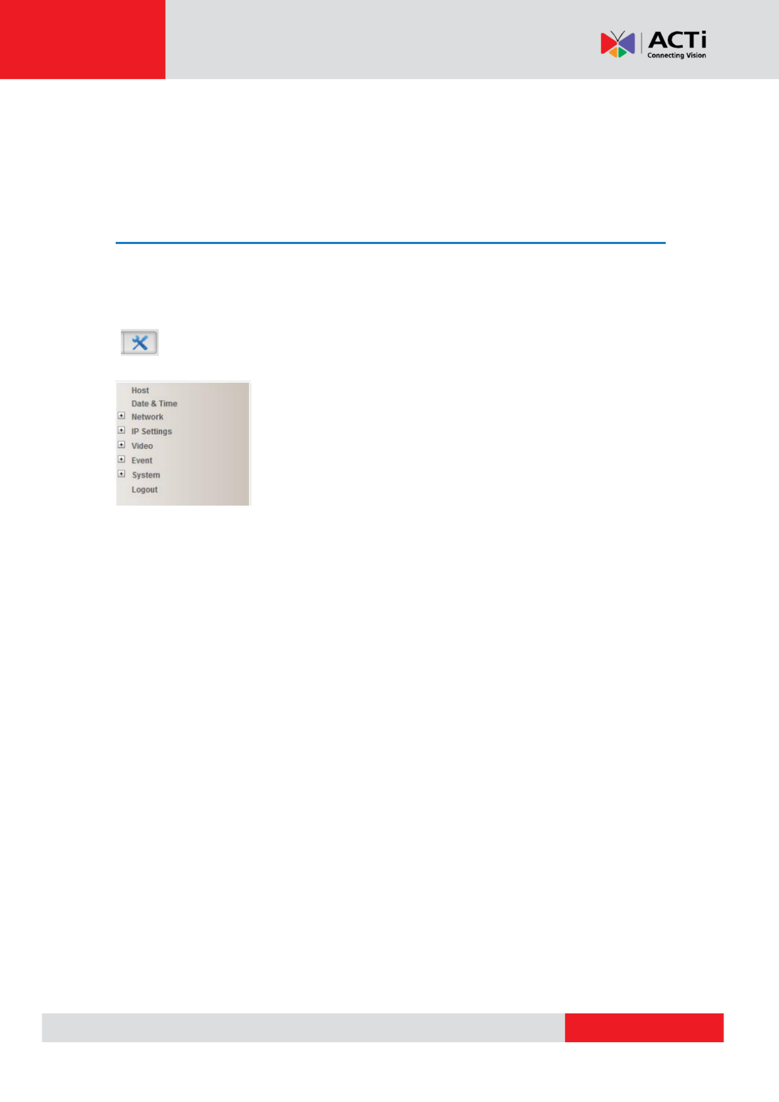
The left side of the Setup page contains the list of Setup items.
Notice: The exact content of the menu list varies for each camera,
depending on the actual capabilities of each camera. This manual,
however, is designed to explain all the possible functions.
Several items in the Setup page are divided into groups, such as Network, IP Settings, etc. You
can expand the groups to see the sub-items by pressing the [+] button.
The following chapters of this manual explain each Setup item separately. The chapters are listed
in the same order as the list of Setup menu items.
www.acti.com
Firmware User
Firmware User
Firmware User
Firmware UserFirmware User’
’
’
’’s Manual V6.03
s Manual V6.03
s Manual V6.03
s Manual V6.03s Manual V6.03 3
3
3
3 3
.0
.0
.0
.0.0
16
Host
Host
Host
Host Host
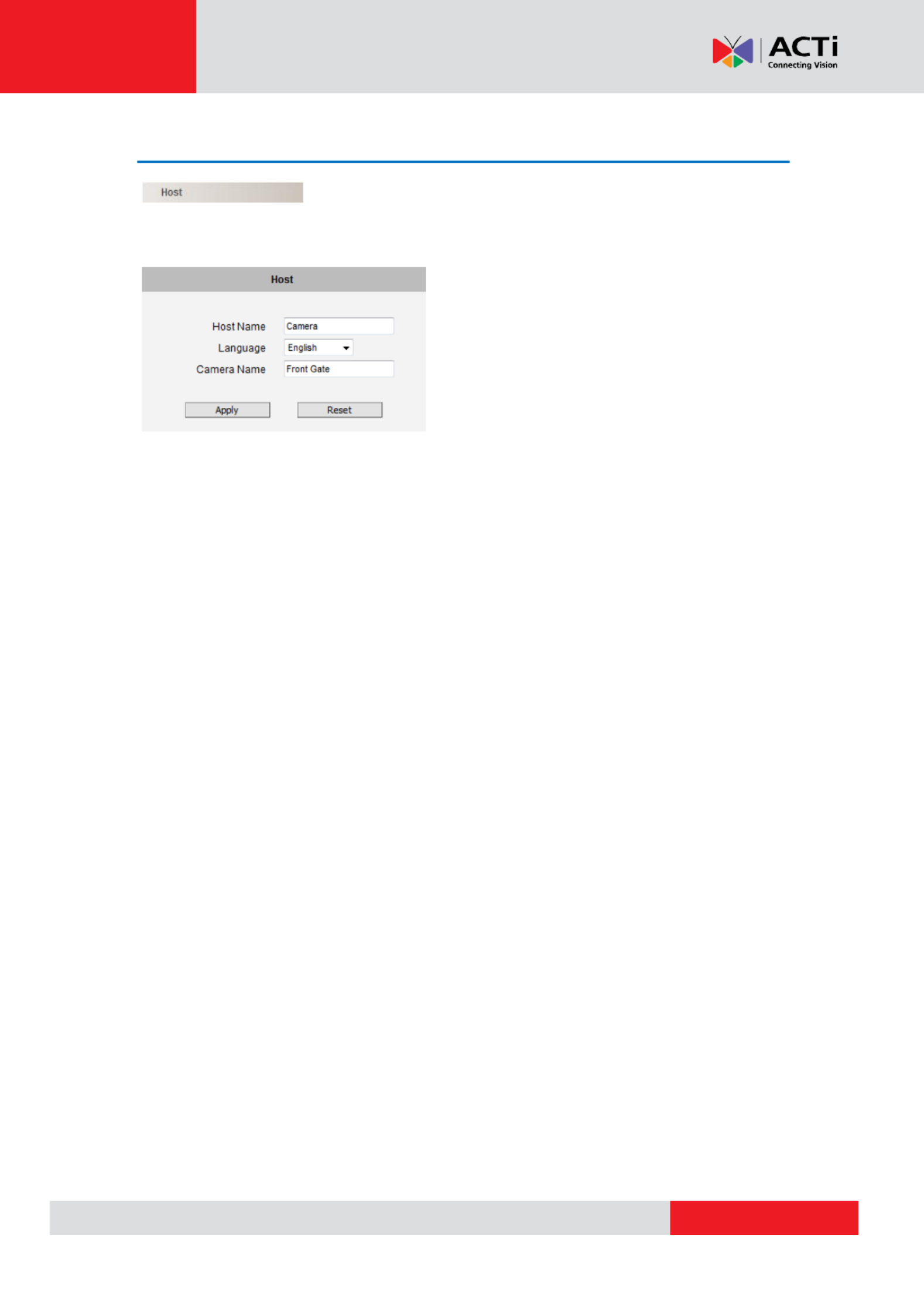
The section “ ”Host allows the administrator to define the name of the
camera and preferred user interface language.
There are two kinds of names Host Name and Camera Name. –
Host Name is used to identify the camera by a DHCP server. In some networks with very strict
security policy, it is required that all the network devices should have their host name, and when
the devices attempt to access the network by requesting an IP address from a DHCP server, the
DHCP server would check if the host name is among the allowed devices. On this page, it is
possible to edit the Host Name. To actually include the Host Name in DHCP discovery packet sent
from a camera, please go to and make sure the device is in IP Settings Dynamic IP Address
mode and “ name”Use host is checked.
Camera Name is used to identify the device by or by Video Management System Software
Tools. Usually, upon installation of the camera, the actual installation location is used as an
easy- -remember Camera Name, such as to “Front Gate” or “Elevator 1 . In many cases the VMS is ”
able to modify the Camera Name directly via its own user interface without needing to access
Web Configurator.
Language selection under Host has the same purpose as the one on the login page of Web
Configurator.
After changing any of the items above, press Apply to save the changes The Reset button .
undoes the changes that had just been made but not Applied yet.

www.acti.com
Firmware User
Firmware User
Firmware User
Firmware UserFirmware User’
’
’
’’s Manual V6.03
s Manual V6.03
s Manual V6.03
s Manual V6.03s Manual V6.03 3
3
3
3 3
.0
.0
.0
.0.0
17
Date
Date
Date
Date Date & T
& T
& T
& T& Time
ime
ime
ime ime
Each video frame contains a time stamp. The accuracy of the time stamp is very important for
incident investigators. Therefore the clock of the camera has to be adjusted to most accurate time
possible.
The section provides the options for adjusting the date Date & Time
and time of the camera.
There are two ways to adjust the date and time by getting date and time – automatically
regularly from any of the worldwide, or by selecting proper time zone, NTP servers manually
date and time. The automatic way can be used only if the camera has an access to NTP servers.
If you are using an isolated Local Area Network without Internet access, you can only use Manual
date and time adjustment mode.
When choosing for automatic date and time updating, you can key in the IP SNTP/NTP Server
address of the NTP server and the time interval for automatic time synchronization. If you want to
key in the domain name of NTP server instead, please make sure the DNS server IP address has
been set under IP Settings; otherwise the camera will not be able to resolve the domain name of
the NTP server.

www.acti.com
Firmware User
Firmware User
Firmware User
Firmware UserFirmware User’
’
’
’’s Manual V6.03
s Manual V6.03
s Manual V6.03
s Manual V6.03s Manual V6.03 3
3
3
3 3
.0
.0
.0
.0.0
18
If all the cameras are getting the date and time from the same NTP Server, you can be most sure
that the video clips from different cameras can be well synchronized later for comparison
purposes.
To choose the most suitable NTP Server to synchronize date and time with, please refer to the
worldwide pool of NTP Servers: http://www.pool.ntp.org/en/
When choosing mode, you can adjust the date and time by the select boxes. Set Manually
Choose the appropriate from the select box, too. If your location is not listed there, Time Zone
then pick any of the listed zones which GMT is identical with your location.
For the countries with daylight saving policy, there is function with two different Day Light Saving
types:
Type 1 number of the week define the starting or ending time of daylight saving period by the –
in the month (First, Second, Third or Last week).
Type 2 define the starting or ending time of daylight saving period by the – exact date in the
month -31). (1
Whether to choose Type 1 or Type 2, please refer to the daylight saving policy of given country.
After changing any of the items above, press to save the changes The Reset button Apply .
undoes the changes that had just been made but not Applied yet.

www.acti.com
Firmware User
Firmware User
Firmware User
Firmware UserFirmware User’
’
’
’’s Manual V6.03
s Manual V6.03
s Manual V6.03
s Manual V6.03s Manual V6.03 3
3
3
3 3
.0
.0
.0
.0.0
19
Network
Network
Network
NetworkNetwork
The section provides the list of network related functions Network
and services. The [+] mark before Network indicates that the list can be expanded by clicking on it.
Once expanded, the list can later be collapsed again by clicking on the [- ] mark.
IP Address Filtering
By function it is possible to define which “ ”IP Address Filtering
devices (their IP addresses) are allowed to connect to this camera, and which devices are
forbidden to connect to this camera.
Check the box Enabled to activate the IP address filtering function and press Apply. “ ”
Below you can select either Allowed“ ” “ or Blocked list to add items there and Enable them with ”
the checkbox behind each row.

www.acti.com
Firmware User
Firmware User
Firmware User
Firmware UserFirmware User’
’
’
’’s Manual V6.03
s Manual V6.03
s Manual V6.03
s Manual V6.03s Manual V6.03 3
3
3
3 3
.0
.0
.0
.0.0
20
“ ”Allowed mode will refuse access to all IP addresses except the ones listed below.
“ ”Blocked mode will accept all incoming access except the IP addresses listed below.
Using (Subnet Mask) allows you to set filtering for a whole range of IP address at once, Netmask
without the need to enter all of them individually. If you are not sure about the function of Netmask,
then you should use 255.255.255.255, and it will affect only a single IP address per line of entry,
or use 255.255.255.0 to use the same setting for all IP addresses starting with the same three
numbers. .
After changing any of the items above, press to save the changes The Reset button Apply .
undoes the changes that had just been made but not Applied yet.
Warning! Do not accidentally block your own IP address that you are connecting from; otherwise
you will not be able to access the camera any more to undo the changes. If this happens by
mistake, you can do the hardware rese it will clear all the filtering rules. t –
www.acti.com
Firmware User
Firmware User
Firmware User
Firmware UserFirmware User’
’
’
’’s Manual V6.03
s Manual V6.03
s Manual V6.03
s Manual V6.03s Manual V6.03 3
3
3
3 3
.0
.0
.0
.0.0
22
HTT PS
HTTPS protocol allows creating a secure channel over an insecure
network in order to protect the data sent between the camera and its counterpart. Two things are
required to have a secure communication encrypted data, and verified counterpart of the –
communication. To make sure that the messages are being sent and received from true
counterpart, the certificate is needed.
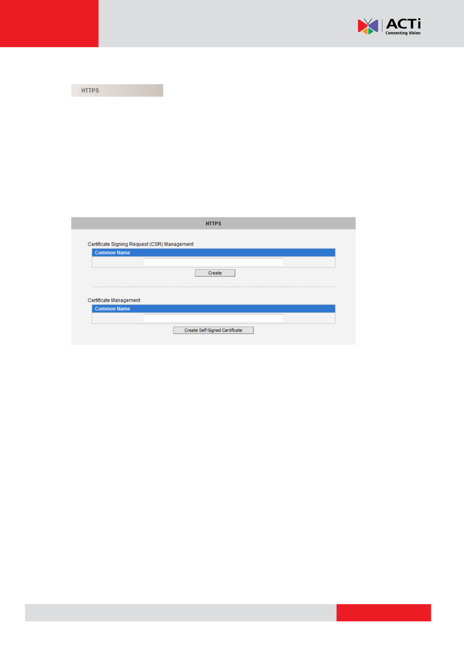
There are two methods to create certificates and – Certificate Signing Request (CSR)
Self-Signed Certificate.
Certificate Signing Request (CSR): User uses a signed certificate issued by trusted
Certification Authority (CA).
Self-Signed Certificate: User wants to use the certificate created and issued by user himself.
Press Create“ ” or Create Self-Signed Certificate button and configure settings in the -“ ” pop up
screen to install the certificate.
Note that the new setting will only take effect after Save & Reboot . “ ”

www.acti.com
Firmware User
Firmware User
Firmware User
Firmware UserFirmware User’
’
’
’’s Manual V6.03
s Manual V6.03
s Manual V6.03
s Manual V6.03s Manual V6.03 3
3
3
3 3
.0
.0
.0
.0.0
23
IEEE 802.1X
IEEE 802.1X is an IEEE standard for port-based Network Access
Control. 802.1X authentication involves three parties: a supplicant, an authenticator, and an
authentication server.
The supplicant is a client device (such as an IP camera) that wishes to attach to the LAN/WLAN.
The authenticator is a network device, such as an Ethernet switch or wireless access point; and
the authentication server is typically a host running software supporting the RADIUS and EAP
protocols.
The authenticator acts like a security guard to a protected network. The supplicant (i.e., client
device) is not allowed access through the authenticator to the protected side of the network until
the supplicant’s identity has been validated and authorized. An analogy to this is providing a valid
passport at an airport before being allowed to pass through security to the terminal. With 802.1X
port-based authentication, the supplicant provides credentials, such as user name / password or
digital certificate, to the authenticator, and the authenticator forwards the credentials to the
authentication server for verification. If the authentication server determines the credentials are
valid, the supplicant (client device) is allowed to access resources located on the protected side
of the network.
Please IEEE 802.1x and configure settings the screen below. Note that the new setting enable on
will only take effect after “Save & Reboot . ”
EAPOL Version V1 and V2 are the 802.1X communication types. and User name User
password area created by user and set in RADIUS server. are Certificates and Private Key
provided by RADIUS Server.

www.acti.com
Firmware User
Firmware User
Firmware User
Firmware UserFirmware User’
’
’
’’s Manual V6.03
s Manual V6.03
s Manual V6.03
s Manual V6.03s Manual V6.03 3
3
3
3 3
.0
.0
.0
.0.0
24
If certificates or private key exist already, there will be a button behind these items, in “ ”Remove
order to remove these items when necessary.
After changing any of the items above, press to save the changes. The Reset button Apply
undoes the changes that had just been made but not Applied yet.

www.acti.com
Firmware User
Firmware User
Firmware User
Firmware UserFirmware User’
’
’
’’s Manual V6.03
s Manual V6.03
s Manual V6.03
s Manual V6.03s Manual V6.03 3
3
3
3 3
.0
.0
.0
.0.0
25
SNMP Setting
T item displays the SNMP configuration p he SNMP Setting age.
SNMP provides an easy way to manage network devices. The main features are:
1. Monitoring device uptime
2. System detail description. (Ex: model name, model description and firmware version.)
3. Collect interface information. (Ex: MAC address, interface speed, local port.)
4. Measuring network interface throughput.
To use SNMP, just SNMP function in the camera (SNMP agents) and run SNMP enable
management software in server (NMS: Network Management Station) to connect the devices. to
The SNMP agent supports versions V1, V2 and V3. SNMP V1 is the initial implementation of
SNMP. SNMP V2 is proposed to enhance the performance of management, such as the
communication of server and devices, the confirmation of information delivery and receipt.
Primary additions in SNMP V3 concern security and remote configuration enhancements.
SNMP V1/V2 uses “Community” name as password to authenticate identity. “Read Community” is
the password for server to get information from devices. “Write Community” is the password for
server to edit values on devices. The default is “public” for Read Community and “write” for Write
Community. Of course, you can set any other password as your read/write community.
You can enable V1, V2 or both. Click “ ” after you’ve comApply pleted setup.
The security method of SNMP V3 uses account/password for authentication. “Security Name” is
the account name to be used with your “Password”. The default security name is “public” and the
password must be at least 8 characters long. You also can set any other security name or
password. Click “Apply” after you’ve completed setup.
www.acti.com
Firmware User
Firmware User
Firmware User
Firmware UserFirmware User’
’
’
’’s Manual V6.03
s Manual V6.03
s Manual V6.03
s Manual V6.03s Manual V6.03 3
3
3
3 3
.0
.0
.0
.0.0
27
RTP
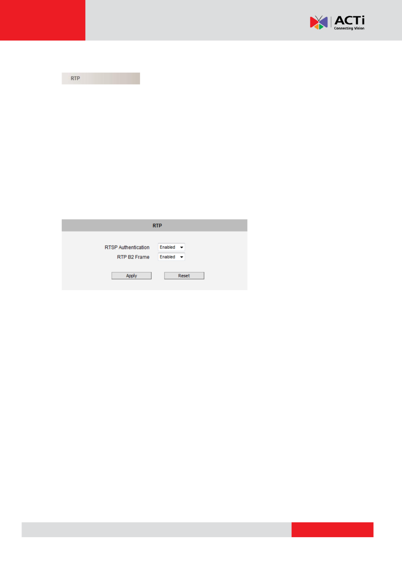
The section allows user to configure RTP Settings RTP .
If the RTSP Authentication is “ ”Enabled , then the RTP streaming will require account name and
password authentication.
If the is then the B2 frame is added to every video frame, containing RTP B2 Frame “ ”Enabled
additional information, such as motion detection status on each frame, digital input and
digital output levels, passive infrared status, other video intelligence data, frame counter,
frame-rate mode and the frame-rate, bitrate, resolution, timestamp and much more. The
user side can operate with video data easily, including event management, storage consumption
estimation, image resizing for preview, etc.
After changing any of the items above, press to save the changes. The Reset button Apply
undoes the changes that had just been made but not Applied yet.
www.acti.com
Firmware User
Firmware User
Firmware User
Firmware UserFirmware User’
’
’
’’s Manual V6.03
s Manual V6.03
s Manual V6.03
s Manual V6.03s Manual V6.03 3
3
3
3 3
.0
.0
.0
.0.0
28
Network (ToS, UPnP, Bonjour, ONVIF)
The section Network contains the controls for following functions:
Type of Service
UPnP
Bonjour
ONVIF
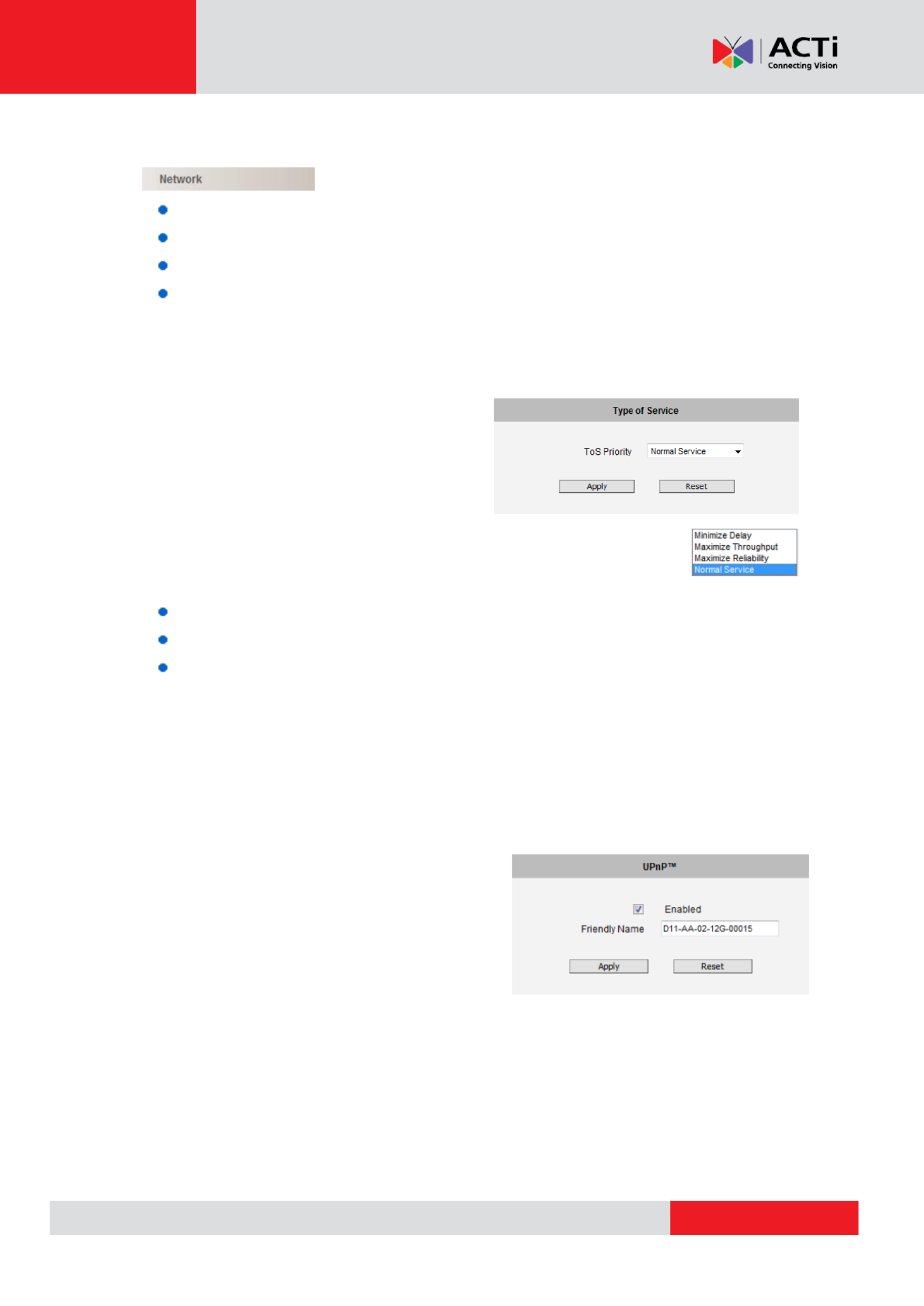
Type of Service
The “Type of Service” provides 4 options to define
the priorities of how the data from the camera
should be handled by the routers that support
ToS concept. By the default, the ToS priority is set
as “ ”Normal Service .
For special priority arrangement, there are 3 more options:
Minimize Delay
Maximize Throughput
Maximize Reliability
After changing any of the items above, press to save the changes. The Reset button Apply
undoes the changes that had just been made but not Applied yet.
UPnPTM
The section UPnPTM provides the option to enable
or disable the Universal Plug and Play capability of
the camera. Having the UPnPTM enabled allows the
other network devices to seamlessly discover it on
the network for convenient identification and access.
The is a hum -readable name for the device that will be displayed when the Friendly Name an
camera is found. By default, the serial number of the camera is used as a friendly name; however,
the user can modify the name according to the project needs.
After changing any of the items above, press to save the changes. The Reset button Apply
undoes the changes that had just been made but not Applied yet.

www.acti.com
Firmware User
Firmware User
Firmware User
Firmware UserFirmware User’
’
’
’’s Manual V6.03
s Manual V6.03
s Manual V6.03
s Manual V6.03s Manual V6.03 3
3
3
3 3
.0
.0
.0
.0.0
29
Most of the Windows-based computers have the capability to discover the devices that support
UPnPTM. Below is the example of Windows 7: clicking on the icon of , the by Network Windows 7
PC will discover the cameras instantly.
Bonjour
The section provides the option to enable or Bonjour
disable the ability of the camera to be discovered by
the other network devices using Bonjour protocol,
developed by Apple Inc. Both Bonjour and UPnP serve
the similar purpose to discover devices conveniently. –
Similarly to UPnP, the human readable can be defined by the user. That name will Friendly Name
be displayed when the camera is found in the network. By default, the Friendly Name is the serial
number of the camera; however, the user can modify the name according to the project needs.
After changing any of the items above, press to save the changes. The Reset button Apply
undoes the changes that had just been made but not Applied yet.

www.acti.com
Firmware User
Firmware User
Firmware User
Firmware UserFirmware User’
’
’
’’s Manual V6.03
s Manual V6.03
s Manual V6.03
s Manual V6.03s Manual V6.03 3
3
3
3 3
.0
.0
.0
.0.0
30
ONVIF
The camera with given firmware is ONVIF 2.2 compliant. By default, the ONVIF function is
disabled.
To enable to the ONVIF support, check the box and
press . Apply
If you need to activate ONVIF on multiple cameras conveniently, you may use the IP Utility
instead, using cgi and system ONVIF_STATE=1 as URL command.

www.acti.com
Firmware User
Firmware User
Firmware User
Firmware UserFirmware User’
’
’
’’s Manual V6.03
s Manual V6.03
s Manual V6.03
s Manual V6.03s Manual V6.03 3
3
3
3 3
.0
.0
.0
.0.0
31
IP Setti
IP Setti
IP Setti
IP SettiIP Settings
ngs
ngs
ngs ngs
The section IP Settings provides the options to define how the camera
would obtain its IP address; and to which DNS server should the camera connect to, in order to
resolve domain names.
Connection Type
The sub-section Connection Type allows defining the method of
obtaining the IP address of the camera. By default, the camera is in mode Dynamic IP Address
and attempts to get the IP address from a DHCP server. If such attempt fails after several
seconds (for example the DHCP server does not exist), the camera will automatically assign itself
an IP address, listed under Static IP Address.
Host Name is used to identify the camera by a DHCP server. In some networks with very strict
security policy, it is required that all the network devices should have their host name, and when
the devices attempt to access the network by requesting an IP address from a DHCP server, the
DHCP server would check if the host name is among the allowed devices. On this page, it is
possible to edit the Host Name and enable or disable the use of host name.
Most installation projects include clear network topology and static IP addresses for each camera.
In such cases, you can change the camera to Static IP Address IP mode and modify the
Address, Subnet Mask Gateway and accordingly.
In some rare cases, the camera may be connected to the control center over Internet. Usually, the
most cost efficient way is to use ADSL connection with . To avoid the unexpected changes PPPoE
of IP addresses by Internet Service Provider upon the restart of the camera, it is recommended to
activate a DDNS service for such scenario, and let the control center connect to the camera by

www.acti.com
Firmware User
Firmware User
Firmware User
Firmware UserFirmware User’
’
’
’’s Manual V6.03
s Manual V6.03
s Manual V6.03
s Manual V6.03s Manual V6.03 3
3
3
3 3
.0
.0
.0
.0.0
32
the domain name instead. Please refer to the DDNS section for more details.
To set the camera in PPPoE mode, set the radio button to PPPoE and key in the User Name and
Password, provided by Internet Service Provider.
After changing any of the items above, press to save the changes. The Reset button Apply
undoes the changes that had just been made but not Applied yet.
New IP address settings will only take effect after pressing . System -> Save & Reboot

www.acti.com
Firmware User
Firmware User
Firmware User
Firmware UserFirmware User’
’
’
’’s Manual V6.03
s Manual V6.03
s Manual V6.03
s Manual V6.03s Manual V6.03 3
3
3
3 3
.0
.0
.0
.0.0
33
DNS
T section allows setting up the Domain Name Service for he DNS
the camera. The camera will connect to the DNS server when there is a need to resolve a domain
name for sending data to.
The most common usage is the ftp or e-mail server in the Event Handler section is defined by
using domain names. Without having DNS service configured, the camera would not know how to
resolve the domain names of FTP or e-mail servers.
It is possible to configure both and . The Secondary DNS Primary Secondary DNS servers
Server will be used when the connection to the Primary DNS Server fails.
After changing any of the items above, press to save the changes. The Reset button Apply
undoes the changes that had just been made but not Applied yet.

www.acti.com
Firmware User
Firmware User
Firmware User
Firmware UserFirmware User’
’
’
’’s Manual V6.03
s Manual V6.03
s Manual V6.03
s Manual V6.03s Manual V6.03 3
3
3
3 3
.0
.0
.0
.0.0
34
DDNS
There are surveillance solutions that consist of single
cameras scattered over a wide territory, therefore each of those cameras should be connected to
Internet in order to become accessible by Control Center. For example, the chain stores, bus
stops, currency exchange booths, etc.
In such cases, one of the practical networking solutions is to use DSL modem on camera site and
let the camera obtain the dynamic IP address from the Internet Service Provider through the DSL
modem using PPPoE connection, which is much more cost-effective than applying for static IP
address.
However, there is one drawback in this solution in order to do the remote surveillance from the –
Control Center, the NVR Server in the Control Center has to know the address of the IP camera
at all times in order to get the video stream from the camera. If the camera’s network connection
has been reset for any reason, the camera will get a new IP address through DSL Modem, which
may be different from the previous one. NVR will not know about this change, and the connection
between the camera and NVR will fail.
There however exists a solution that makes sure the NVR can find the camera even if the camera
IP changes frequently. Our cameras support service that allows Dynamic DNS or DDNS
frequently changing IP be mapped to a certain unchangeable domain name. The mapping
database and its updating engine are hosted in one of the Dynamic DNS servers, most of which
offer basic services for free, such as www.dyndns.org.
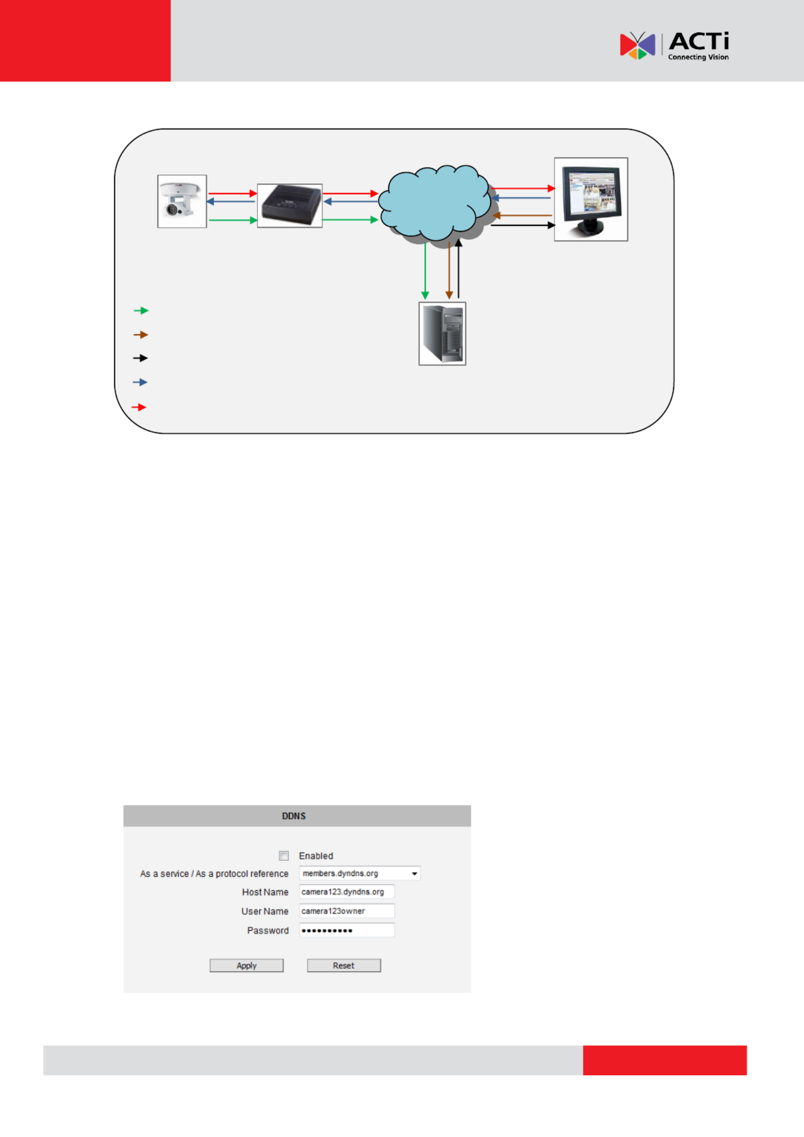
How does it work? Look at the graph below.
Internet
Control Center
(NVR)
IP Camera
DSL Modem
PPPoE Connection with Dynamic IP address
Video Stream from camera to NVR
Commands from NVR to camera’s IP address
www.acti.com
Firmware User
Firmware User
Firmware User
Firmware UserFirmware User’
’
’
’’s Manual V6.03
s Manual V6.03
s Manual V6.03
s Manual V6.03s Manual V6.03 3
3
3
3 3
.0
.0
.0
.0.0
35
Every time the IP camera gets an IP that is different from previous one, it notifies the public DDNS
Service about the change. The DDNS Service updates its database immediately, mapping the
assigned domain name (for example ) to the new IP address. In NVR camera123.dyndns.org
settings, only the domain name ( ) is used to identify the camera. Every camera123.dyndns.org
time when NVR needs to connect to the camera, it asks from DDNS Service what the current
camera’s IP is. The DDNS Service instantly responds to NVR and tells it the camera’s IP. Now
NVR will use the IP of the camera to connect to the camera and the video stream from the
camera to NVR can be initiated.
As a result, NVR can always find the IP camera regardless of frequently changing IP address of
the camera. Since there are so many public DDNS Services available for free, the PPPoE-based
connection is really a good and low-cost solution for single-camera sites.
Internet
Control Center
(NVR)
IP Camera
DSL Modem
Using Dynamic DNS
DDNS Service
Camera notifies DDNS service when IP changed
NVR uses camera’s domain name to ask DDNS
DDNS tells the NVR what the camera’s IP is
Commands from NVR to camera’s IP address
Video Stream from camera to NVR

www.acti.com
Firmware User
Firmware User
Firmware User
Firmware UserFirmware User’
’
’
’’s Manual V6.03
s Manual V6.03
s Manual V6.03
s Manual V6.03s Manual V6.03 3
3
3
3 3
.0
.0
.0
.0.0
36
To activate DDNS, please check the „ “Enabled . Select the service reference, input the Host
Name User Name Password (the domain name given to the camera by DDNS service, and of
the DDNS server account.
You will get the needed Host Name, User Name and Password information from the DDNS
service provider once you have registered an account there and requested a domain name for
your camera.
After changing any of the items above, press to save the changes. The Reset button Apply
undoes the changes that had just been made but not Applied yet.

www.acti.com
Firmware User
Firmware User
Firmware User
Firmware UserFirmware User’
’
’
’’s Manual V6.03
s Manual V6.03
s Manual V6.03
s Manual V6.03s Manual V6.03 3
3
3
3 3
.0
.0
.0
.0.0
37
Video
Video
Video
Video Video
The section provides options to adjust the video quality Video the
and configure the streaming details of the camera. The default settings of the camera are
sufficient for most environments and the video adjustments are not necessary. The following
sections explain the ways to configure the video quality or streaming details in case it is required
to do so.
The mark before Video indicates that the list can be expanded by clicking on it. Once [+]
expanded, the list can later be collapsed again by clicking on the mark. [-]
The sub-section is also named Video. For Audio supported cameras,
there will also be a sub-section named Audio. The video section is divided into tabs. The
functionality of each tab is explained separately below.
Upon opening the sub-section named Video, the live view of the Stream 1 of the camera will
appear. Since the camera is a dual stream device, it is possible to see how each of the 2
streaming configurations looks like, by selecting either or Stream-1 Stream-2 under the live video
window.
Usually, Stream-1 is configured to be high quality video with maximum resolution and frame rate
for recording purposes while Stream-2 is usually a moderate quality stream for live view purposes
of the VMS, to reduce VMS computing power during video decoding of multiple channels.
www.acti.com
Firmware User
Firmware User
Firmware User
Firmware UserFirmware User’
’
’
’’s Manual V6.03
s Manual V6.03
s Manual V6.03
s Manual V6.03s Manual V6.03 3
3
3
3 3
.0
.0
.0
.0.0
38
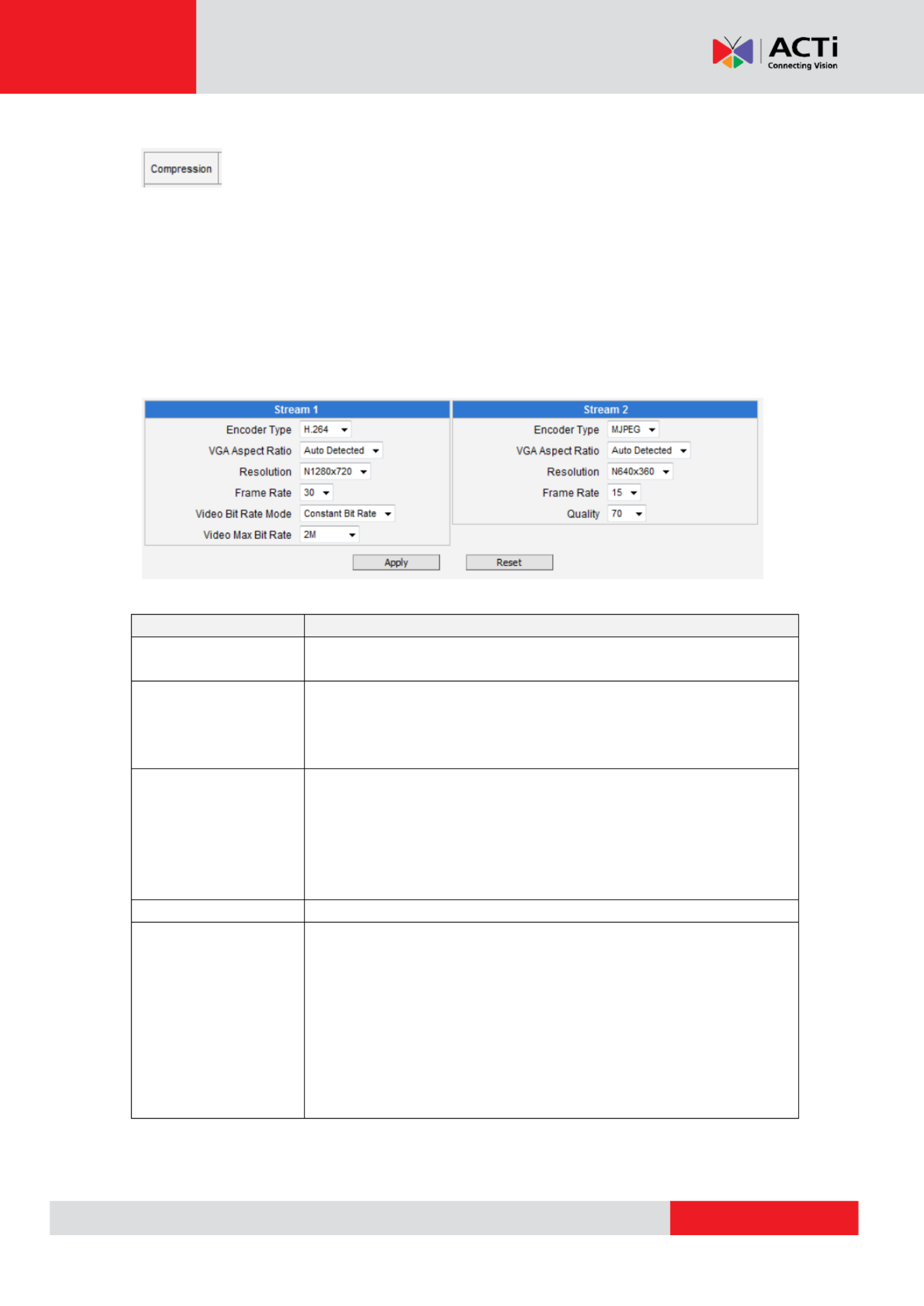
Compression
The section Compression allows the user to define the compression settings of “ ”
the video stream 1 and stream 2. The purpose of compression is to reduce the bandwidth and
VMS storage consumption.
Usually the stream 1 is configured to be the best quality stream for NVR recording purposes while
the stream 2 is configured to be with the basic quality for the live view of NVR, to minimize the
computing power of NVR used for video decoding.
Parameters
Description
Encoder Type
There are two encoder types available: H.264 (High Profile) and
MJPEG.
VGA Aspect Ratio
It is used to define the aspect ratio of VGA stream it can be either –
4:3 ratio (640x480) or 16:9 ratio (640x360). When Auto Detected is “ ”
chosen, the VGA stream will follow the ratio of the higher resolution
stream, to ensure the identical view of stream 1 and stream 2.
Resolution
Depending on the camera model, the number of available resolutions
may be different. The default resolution setting of the camera may not
necessarily be the maximum resolution of the camera. If the user
wants to use the maximum resolution, it is possible to do it here. The
maximum possible resolution of the stream 2 will be smaller than
stream 1.
Frame Rate
Defines the amount of frames per second.
Video Bit Rate Mode
(only for H.264)
Under Constant Bit Rate“ ” mode (CBR), the camera keeps the stable
bitrate regardless of the complexity of the scene. Under this mode, the
video quality may vary if the bit rate value is set too low. It is easier to
do storage and network bandwidth consumption estimations under
this mode compared to Variable Bit Rate mode.
Under Variable Bit Rate“ ” mode (VBR), the camera will keep the video
quality stable while the bit rate may occasionally go up or down,
depending on the complexity of the scene.

www.acti.com
Firmware User
Firmware User
Firmware User
Firmware UserFirmware User’
’
’
’’s Manual V6.03
s Manual V6.03
s Manual V6.03
s Manual V6.03s Manual V6.03 3
3
3
3 3
.0
.0
.0
.0.0
40
Motion Detection
The section Motion Detection“ ” allows the user to configure the video motion
detection system of the camera. Motion detection regions are based on the Stream 1. By default,
all the regions are disabled.
Click on Setup“ ” to adjust the motion detection regions or its parameters. Microsoft Internet
Explorer browser is required to configure the motion detection regions.
There are three independently configurable motion detection regions in the camera. Each
motion detection region has 6 configuration parameters:
Enabled or disabled
Location of the region
Size of the region
Sensitivity
Trigger threshold
Trigger interval

www.acti.com
Firmware User
Firmware User
Firmware User
Firmware UserFirmware User’
’
’
’’s Manual V6.03
s Manual V6.03
s Manual V6.03
s Manual V6.03s Manual V6.03 3
3
3
3 3
.0
.0
.0
.0.0
41
Enabled or disabled
Each of the 3 motion detection regions can be enabled or disabled
individually. Look at the example: Only the region 1 is enabled while
2 and 3 are disabled. The disabled regions disappear from the video
display.
Note that the number of the motion detection region is written in
the upper left corner of the region.
Location of the region
You can move the motion detection region anywhere on the field of
view by dragging the top of the motion detection rectangle as
shown on the image. The motion detection regions may even be
overlapping if you like.
Size of the region
By dragging the lower right corner of the motion detection region
you can change the size of the region. The maximum size of the
region can even be as big as the whole screen.
Sensitivity
Sensitivity is the parameter that helps us distinguish actual moving targets (people, vehicles) from
the slightly moving background, such as leaves of the trees waving in the wind. In order to avoid
false alarms, we might want the camera be able to ignore small motion. The higher is the
sensitivity level of the camera the smaller shift of the object is needed to trigger the alarm. For
example, if the object within motion detection region has moved for about 1-3 pixels during two
video frames, then such small motion will be discarded by camera if the sensitivity is low, and will
still trigger an alarm if the sensitivity is high. In other words, you can think of sensitivity level as a
reversed speed limit the smaller is the sensitivity, the faster are the objects allowed to move –
without being detected.
The biggest challenge of motion detection configuration is to find the settings that do not produce
false alarms and at the same time do not miss any actual intrusions. The rule of thumb is: the
sensitivity should be as high as possible while not producing false alarms. The default
sensitivity level of the cameras is 70 (on a scale of 0-100) and it is a good setting for most
standard cases.
www.acti.com
Firmware User
Firmware User
Firmware User
Firmware UserFirmware User’
’
’
’’s Manual V6.03
s Manual V6.03
s Manual V6.03
s Manual V6.03s Manual V6.03 3
3
3
3 3
.0
.0
.0
.0.0
42
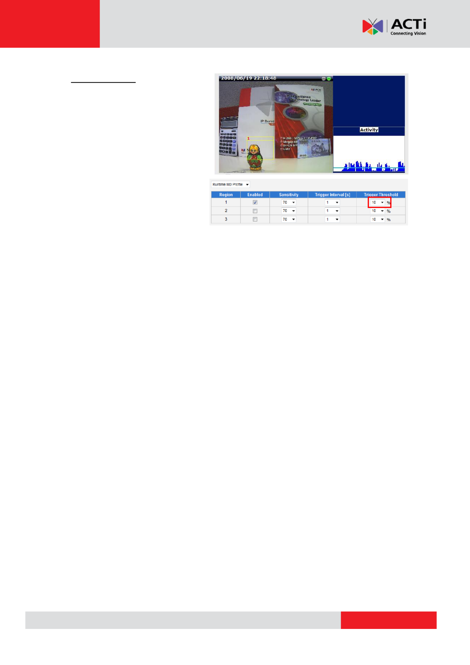
Trigger threshold
Look at the moving object entering the
area of motion detection: although
moving quite slowly, it caused motion
activity several pixel regions reported –
a motion that was faster than allowed
“ ”speed limit of sensitivity (70).
The blue graph on the right side of
the image shows how many percent
of pixels within the motion detection
region were considered as currently in motion . The activity panel itself is a timeline for each “ ” –
moment of time you can see the height of the blue bars. You may notice that at certain moment
the tallest bars in the activity graph reached about 25% (a quarter of the total height in activity
panel) it means, 25% of this motion detection area were filled with moving pixels at that moment. –
By visual observation you can also see that the object standing inside the motion detection region
indeed covers about 25% of its size.
What if the object is really small but moves rather fast (gets triggered by the current sensitivity
level)? For example, we want to detect people but not the cat walking in the room. Although both
people and cat may move with the speed that will trigger motion, they have different size of
triggered pixels. For example, a human passing by the motion detection region will trigger 25% of
pixels in that region while the cat would trigger only 2%. Since we want to have a real alarm in
case of human or vehicle passing by while ignoring birds, cats, butterflies, mice, etc, we need a
filter that can define how many percent of triggered pixels will be considered as a real alarm. This
parameter is called . The default value of trigger threshold is 10%. It means, trigger threshold
only the objects that are bigger than 10% of the motion detection region size and move faster
than allowed by sensitivity level (70) will produce actual alarm.
How to choose the most optimal trigger threshold level? The rule of thumb, keep the trigger
threshold as small as possible while not causing false alarms by the moving objects that
are not humans or vehicles.
You can have different sensitivity level and trigger threshold level for each motion detection
region.
In order to understand all of the above even better, please refer to the table below containing four

www.acti.com
Firmware User
Firmware User
Firmware User
Firmware UserFirmware User’
’
’
’’s Manual V6.03
s Manual V6.03
s Manual V6.03
s Manual V6.03s Manual V6.03 3
3
3
3 3
.0
.0
.0
.0.0
43
possible combinations of settings using sensitivity level and trigger threshold percentage.
The objects listed in each cell will trigger an alarm under given settings:
Low threshold (0-5 %)
High threshold (5-100%)
Low sensitivity
(0-65)
Big and fast
Small and fast
Big and fast
High sensitivity
(65-100)
Big and fast
Big and slow
Small and fast
Small and slow
Big and fast
Big and slow
The camera’s default sensitivity is 70 and threshold 10%. By these default values, only is
the rabbit and the turtle would trigger an alarm while the butterfly and the snail would be
ignored by the motion detection system.
Important: Please remember that changing the size of the motion detection region has an impact
on the threshold the bigger is the size of the motion detection region the smaller should be the –
threshold value if you want the same object size to trigger motion. For example, if you increase
the motion detection region to twice the previous size, please remember to reduce the threshold
to half its original value (from 10% to 5%). On the other hand, changing the location of the motion
detection region has no impact on threshold.
Trigger interval
The last configuration item is the trigger interval. It is the time period from the beginning of the
triggered event during which the all motion activities are ignored by the camera. This is designed
to avoid needless repetitive reporting of the same intrusion. Trigger interval 20 seconds would
mean that when the even happens, camera will take certain one-time actions and ignore the
continuing activity in the motion detection region for 20 seconds. When 20 seconds are over, the

www.acti.com
Firmware User
Firmware User
Firmware User
Firmware UserFirmware User’
’
’
’’s Manual V6.03
s Manual V6.03
s Manual V6.03
s Manual V6.03s Manual V6.03 3
3
3
3 3
.0
.0
.0
.0.0
44
camera will produce a new alarm if there are still action in the motion detection region, and take
actions again.
There is one more item on the Motion Detection configuration
page which was not explained above the – Profile of Motion
Detection. Think of them as (Runtime MD Profile) and Profile 1
Profile 2 (Event MD Profile). It means that you can configure two
independent groups of Motion Detection regions with at most 3 regions in each group. Normally,
the Profile 1 (Runtime MD Profile) is used as an active profile of the camera. However, in some
cases it is possible to let camera switch to Profile 2 by using the Event Handler system of the the
camera.
For example, you might want to have different motion detection parameters for day and night time.
Then the two profiles become really handy. In such case, remember to configure the motion
detection parameters for both profiles before moving on to configure the event response system.
After changing any of the items above, press to save the changes. The Reset button Apply
undoes the changes that had just been made but not Applied yet.

www.acti.com
Firmware User
Firmware User
Firmware User
Firmware UserFirmware User’
’
’
’’s Manual V6.03
s Manual V6.03
s Manual V6.03
s Manual V6.03s Manual V6.03 3
3
3
3 3
.0
.0
.0
.0.0
45
Day/Night
e section allows user to control the switching between day mode and Th Day/Night
night mode. This section will be displayed only for day/night models.
Parameters
Description
Day/Night mode
There are three modes:
Auto: The camera will automatically switch between day mode (color)
and night mode (black/white) under certain exposure level, defined by
user at “ ”Switch from Day mode to Night mode .
Day: The camera always stays in day mode (color) regardless of
exposure level.
Night: The camera always stays in night mode (black/white)
regardless of exposure level.
IR LED Control
This feature is visible only in camera with built-in IR LED.
There are two modes:
Auto: The built-in IR LED will be turned on automatically upon day to
night switch and turned off upon night to day switch.
Disabled: The IR LED will be off regardless of day and night mode.
Switch from Day mode
to Night mode
The scale of allows user define the exposure level at which the 0~100
day to night switch should happen. The higher is the value, the darker
the environment has to be to trigger the day to night switch.

www.acti.com
Firmware User
Firmware User
Firmware User
Firmware UserFirmware User’
’
’
’’s Manual V6.03
s Manual V6.03
s Manual V6.03
s Manual V6.03s Manual V6.03 3
3
3
3 3
.0
.0
.0
.0.0
46
Image
The section allows user to control certain parameters of a video frame. Image
Parameters
Description
Video Flipping
Check this box to flip the video up-down. Usually used together with
Video Mirroring to achieve the 180-degree rotation effect.
Video Mirroring
Check this box to mirror the video left-right. Usually used together with
Video Flipping to achieve the 180-degree rotation effect.
Brightness
Select the Brightness value (0~100). The higher the value, the brighter
the image.
Contrast
Select the Contrast level from following options: Lowest, low, medium,
high, highest
Digital Noise
Reduction
Turn ON or OFF the Digital Noise Reduction. When turned on, the
noise on the video (especially in low light) is reduced and image will
look smoother and clearer.
WDR
Choose the WDR level from following options: Disabled, low, medium,
high, highest.
After changing any of the items above, press to save the changes. The Reset button Apply
undoes the changes that had just been made but not Applied yet.
The button “Restore image settings to default” is a quick way of restoring factory default image
settings without needing to reset the whole camera to factory default.
www.acti.com
Firmware User
Firmware User
Firmware User
Firmware UserFirmware User’
’
’
’’s Manual V6.03
s Manual V6.03
s Manual V6.03
s Manual V6.03s Manual V6.03 3
3
3
3 3
.0
.0
.0
.0.0
47
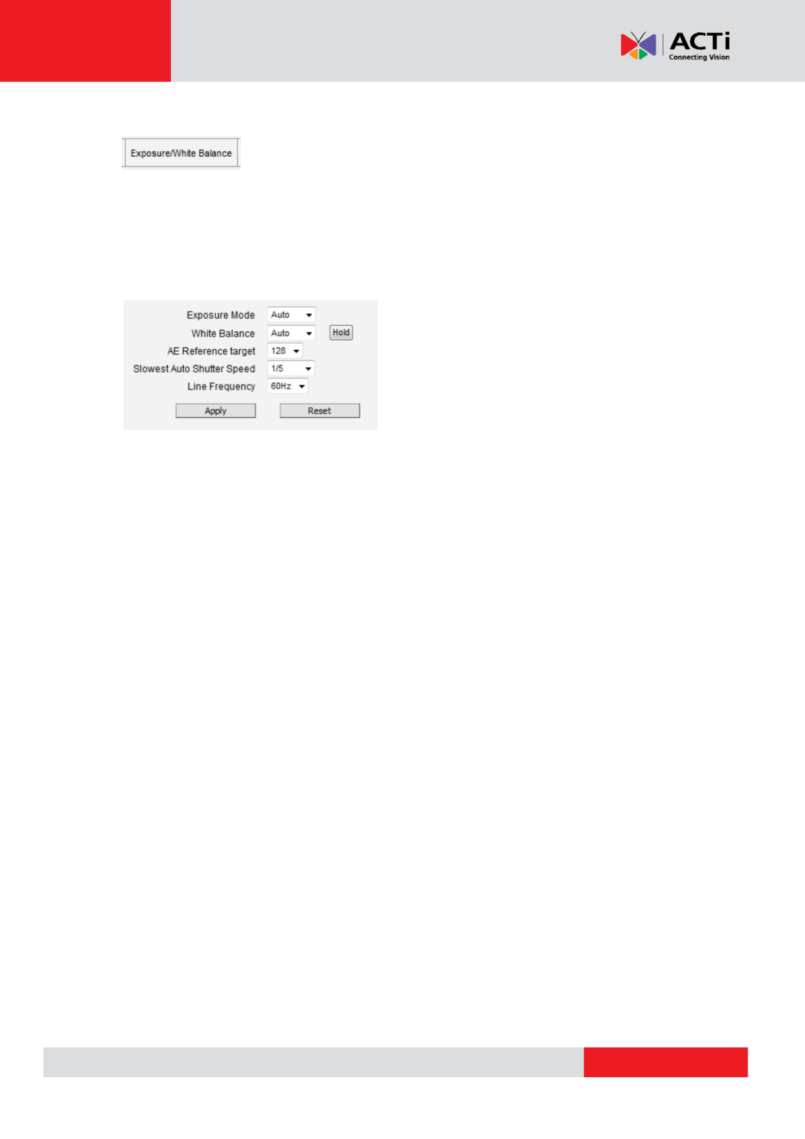
Exposure / White Balance
The section allows the user to c gure Exposure / White Balance onfi
Exposure (shutter, iris and gain control) and White Balance settings. In most cases, the default
settings are sufficient and no adjustment is needed. Some options will only appear under certain
Exposure / White balance modes. Each mode is described in detail below.
Exposure Mode - Auto
In Auto Exposure Mode, you control the image brightness by configuring the AE Reference Target
and Slowest Auto Shutter.
AE Reference Target (Auto Exposure reference target) can be considered as the Target “
Brightness on Sensor The camera will use several internal parameters to achieve best quality ”.
with reference to this. The higher this value, the brighter the overall scene, however, there
may be more noise at night in such case. The range of AE Reference Target is 1~255.
The camera will automatically control shutter speed, auto iris (if available) and signal gain to
achieve the target level set by the user. If the auto iris does not exist or is already opened to a
maximum size, and the image is still darker than the user defined target, it will further slow down
the shutter speed within the allowed range (set by user under Slowest Auto Shutter Speed) and
increase the signal gain.
Slowest Auto Shutter Speed is the user defined threshold for slowest allowed speed of auto
shutter. For example, if by default the shutter speed would vary between 1/5s ~ 1/2000s
depending on the lighting conditions, then setting the Slowest Auto Shutter Speed to 1/30s would
narrow down the auto shutter range to work between 1/30s ~ 1/2000s. The purpose of allowing
user to define the threshold for slowest speed is to avoid motion blur caused by too slow shutter
at night.
It is also important to know that very high shutter speed is not recommended for indoor solutions
with artificial light that flashes with certain frequency, as it may produce flickering effect,
regardless of Exposure mode.

www.acti.com
Firmware User
Firmware User
Firmware User
Firmware UserFirmware User’
’
’
’’s Manual V6.03
s Manual V6.03
s Manual V6.03
s Manual V6.03s Manual V6.03 3
3
3
3 3
.0
.0
.0
.0.0
48
Shutter speed choices according to environment:
Shutter
Speed
1/5
1/13
1/15
1/25
1/30
1/50
1/60
1/100
1/120
1/250
1/500
1/1000
1/2000
Indoor
Y
Y
Y
Y
Y
-
-
-
-
Outdoor
Y
Y
Y
Y
Y
Y
Y
Y
Y
In extreme low light conditions, the shutter speed is slown down to get more light into one image,
but not slower than the user defined threshold .
If the exposure time extends beyond the interval between frames (too slow shutter), (i.e. 1/30
second), then the frame rate will be automatically reduced. Longer time in this value gives
clearer images at night for slow moving objects, but more motion blur for fast moving
objects.
White balance refers to the true white color iscapability of the camera to understand what “ ”.
When the camera knows the true white color, then the rest of the colors will be accurate, too.
While human eye can easily adapt to different lighting sources (even mixed sources, such as sun
light through the window and indoor lights turned on at the same time), the camera has to
understand what is the dominant light source in given scene and what is the white color“ ” of such
light source.
By default the camera is in mode and attempts to recognize the light source auto white balance
and its color spectrum automatically and adjusts the image accordingly. This function works
continuously in the background. It is re-evaluated for each frame, to make sure if there is any
change in dominant light source (e.g. the user closes the curtains to block the sun light and turns
on the indoor lights).
In most cases the auto white balance works perfectly and the user does not have to adjust
anything! In some rare installation cases, especially when there are no white color objects in the
field of view, and the light sources are mixed, the camera may have difficulty to identify the true
white color to fine tune the rest of the colors.
In such cases, the installer can help“ ” the camera to understand the true colors by placing a white
object (for example a piece of white paper) in front of the camera to cover the whole field of view

www.acti.com
Firmware User
Firmware User
Firmware User
Firmware UserFirmware User’
’
’
’’s Manual V6.03
s Manual V6.03
s Manual V6.03
s Manual V6.03s Manual V6.03 3
3
3
3 3
.0
.0
.0
.0.0
49
and wait a few seconds the auto white balance system will adjust the colors until the white –
paper will really look white on the display. At that moment, the user can freeze these white
balance settings by pressing the button. After pressing that button, the White Balance will Hold
switch from Auto mode to Manual mode, together with the color values captured at the moment of
Hold. The user can now remove the white object from the field of view, and the colors will stay
correct for given scene.
For advanced users, there is also an option to switch from Auto mode to of White Manual mode
Balance directly and input the R Gain and B Gain values manually.
Line Frequency is the function that adjusts the shutter speed options to match with the
frequence of artificial light source of given country. For example, in Europe the light frequency
(due to power supply frequency of lights) is 50Hz, that is 50 flashes per second. By setting line
frequency to 50Hz in such case, the shutter speed options will be proportional with light source
frequency, such as 1/25s, 1/50s, 1/100s, etc.
It is necessary to have the camera’s Line Frequency adjusted according to the power
frequency of the light source to avoid flickering effect.
The natural light source (sun light) is a seamless flow of light the Line Frequency setting does –
not matter for the cameras that are only exposed to natural li ght.
After changing any of the items above, press to save the changes. The Reset button Apply
undoes the changes that had just been made but not Applied yet.

www.acti.com
Firmware User
Firmware User
Firmware User
Firmware UserFirmware User’
’
’
’’s Manual V6.03
s Manual V6.03
s Manual V6.03
s Manual V6.03s Manual V6.03 3
3
3
3 3
.0
.0
.0
.0.0
50
Exposure Mode - Manual
When the lighting conditions are stable 24 hours a day, the advanced users may consider using
manual exposure mode, to further fine tune the image quality in order to fulfill the special project
requirements. Please note that in most cases, it is highly recommended to keep the camera in
Auto Exposure mode and let the intelligent system of the camera find the best possible exposure
settings instead.
In manual exposure mode, the user can directly adjust the signal gain and shutter speed manually.
The White Balance and Line Frequency controls have already been explained in previous the
chapter.
After changing any of the items above, press to save the changes. The Reset button Apply
undoes the changes that had just been made but not Applied yet.
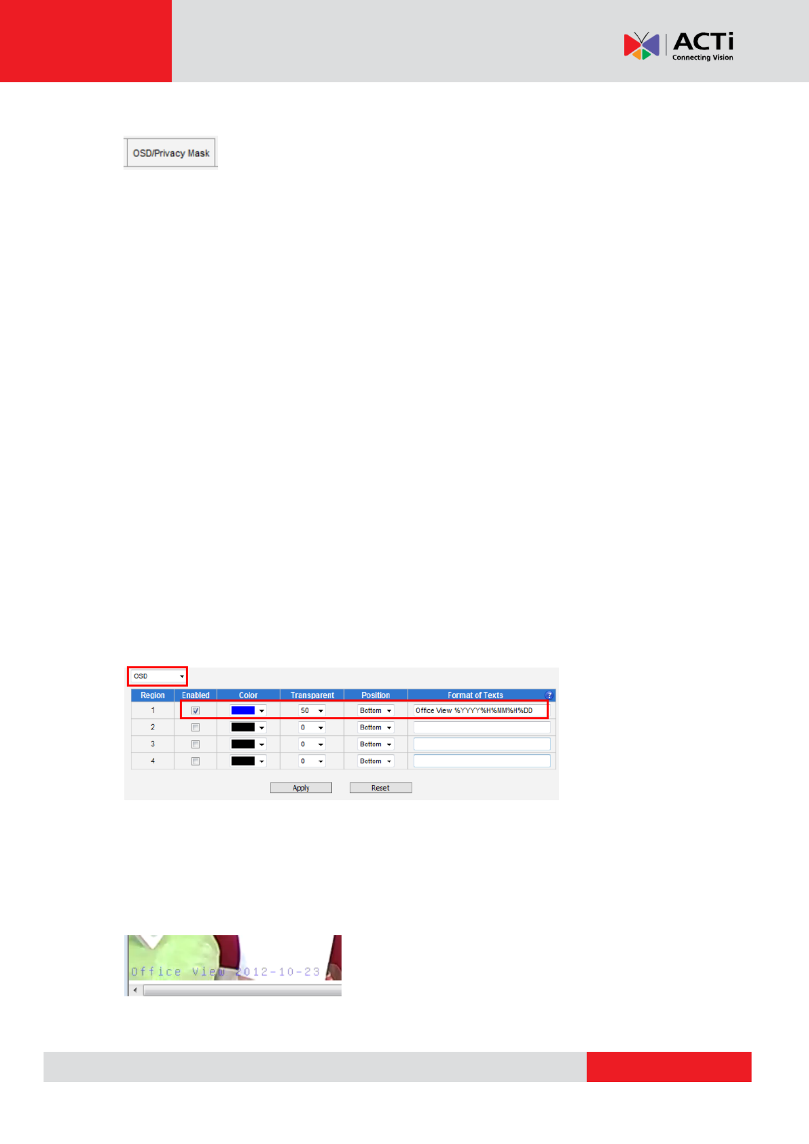
www.acti.com
Firmware User
Firmware User
Firmware User
Firmware UserFirmware User’
’
’
’’s Manual V6.03
s Manual V6.03
s Manual V6.03
s Manual V6.03s Manual V6.03 3
3
3
3 3
.0
.0
.0
.0.0
51
OSD/Privacy Mask
The section allows user to do one of the two on-video OSD / Privacy Mask
operations:
1. Add text to the upper or lower left corner of the video. This function is called Text Overlay or
On-Screen Display (OSD). It is possible to display the camera name, date and time, IP
address or any custom text as Text Overlay. The text is kept as small as possible and is
not resizable. The text can be read normally when the video is enlarged on the display to 1:1
ratio. The purpose of having the text so small is to provide sufficient legal evidence while
blocking the smallest possible area of the video to avoid valuable video evidence being
blocked by text overlay. The text will be embedded into video and cannot be removed later
upon playback or export.
2. Cover up some sensitive areas of the video that should not be captured by the camera, such
as manager’s computer screen or bathroom entrance. This function is called Privacy Mask. It
is possible to configure several independent regions for masking. Microsoft Internet
Explorer browser is required to configure the Privacy Mask. The privacy masks will be
embedded into video and cannot be removed later upon playback or export.
Text Overlay (OSD) Setup
It is possible to define up to 4 regions of text. If more than 1 region of text is and enabled
positioned in the same location, then the texts will appear one below another, row by row.
In the example above, one region of text was enabled with blue color and 50% transparency,
located at left lower corner and containing the text of Office View together with current date. The „ “
date would be automatically changing every day, according to camera’s date and time settings.
The result of the example configuration would look like this (Live View page, 1:1 scale):

www.acti.com
Firmware User
Firmware User
Firmware User
Firmware UserFirmware User’
’
’
’’s Manual V6.03
s Manual V6.03
s Manual V6.03
s Manual V6.03s Manual V6.03 3
3
3
3 3
.0
.0
.0
.0.0
52
Below is the list of characters with special meaning that can be used in the text field:
Parameters
Description
%YYYY
Year in four-digit format. For example, 2008
%YY
Year in two-digit format. For example, 08
%MM
Month in two-digit format. For example, 01 for January, 12 for December
%DD
Date in two-digit format. 01~31
%hh
Hour in two-digit format. 00~23. Note that only -hour indication 24 is
support . ed
%mm
Minutes in two-digit format. 00~59
%ss
Seconds in two-digit format. 00~59
%H
a hyphen, "-"
%C
a colon, ":"
%X
a slash, "/"
%N
show Camera Name (It might be truncated if exceeds max OSD length)
After changing any of the items above, press to save the changes. The Reset button Apply
undoes the changes that had just been made but not Applied yet.
Privacy Mask Setup
It is possible to set up up to 4 regions of privacy masks. The adjustment of the privacy mask
region can be done when region is checked under Setup column. „ “
You may resize and drag the region the
same way as the motion detection
regions: upper bar that contains the
number of the region can be used for
dragging the region across the video
while the white box at the right lower
corner of the privacy mask region can be
used for resizing the region.

www.acti.com
Firmware User
Firmware User
Firmware User
Firmware UserFirmware User’
’
’
’’s Manual V6.03
s Manual V6.03
s Manual V6.03
s Manual V6.03s Manual V6.03 3
3
3
3 3
.0
.0
.0
.0.0
53
There are 4 pre-defined color options for privacy masks. If the user wants to use any other colors,
please use URL commands to set up the privacy mask instead. To do that, please refer to the
Guide that explains the use of URL commands.
When switching back to live view, the privacy mask would look like this:
Please note that the Text Overlay (OSD) and Privacy Masks will take effect for both Stream 1 and
Stream 2.
After changing any of the items above, press to save the changes. The Reset button Apply
undoes the changes that had just been made but not Applied yet.
Notice: It may take several seconds to update the region location on video display after pressing
Apply!

www.acti.com
Firmware User
Firmware User
Firmware User
Firmware UserFirmware User’
’
’
’’s Manual V6.03
s Manual V6.03
s Manual V6.03
s Manual V6.03s Manual V6.03 3
3
3
3 3
.0
.0
.0
.0.0
54
On-Screen Graphics
On-Screen Graphics (OSG) is a new feature that allows placing custom image files on the top of
the video as a layer. For example, it can be used as a watermark for security purposes, or a brand
logo in the corner of the video image.
There is no interface within Web Configurator to configure On-Screen Graphics since it is
a rarely used feature. The URL commands can be used to complete the task instead.
The image that can be used as OSG has to be in YUV format (Image raster graphics before )
uploading to the camera. There are several freeware converters available that convert images to
YUV format.
For example, one free trial version of YUV converter can be downloaded from Sunrayimage.com:
http://www.sunrayimage.com/download/YUVTools_3.0_trial.zip
We do not guarantee the performance, terms of usage or availability of this product. The user has
to read the terms of use first and proceed with installation if the terms are acceptable.
Please note that the image should not be larger than 640x480 pixels and should contain an even
number of pixels. The image, once uploaded, cannot be resized. Therefore, please make sure
that you have the image with the right size before uploading to the camera.
For example, we have the BMP logo with the size 204x106 that has been converted into YUV:
When the image is ready, upload it to the camera by the following URL command:
http://192.168.0.100/cgi-bin/cmd/encoder?OSG_IMAGE
Upon successful entry of user name ans password, the following upload window will appear.
Browse yuv Apply for the file in your computer that you had prepared and press .

www.acti.com
Firmware User
Firmware User
Firmware User
Firmware UserFirmware User’
’
’
’’s Manual V6.03
s Manual V6.03
s Manual V6.03
s Manual V6.03s Manual V6.03 3
3
3
3 3
.0
.0
.0
.0.0
55
When done, use another URL command to configure its position:
http://192.168.0.100/cgi-bin/cmd/encoder?OSG_CONFIG=
1,0,0,240,106,EB8080,4
... where the 7 parameters behind OSG_CONFIG mean following:
Parameter
Position
Description
1
1 means enabled, 0 means disabled
2
X position
3
Y position
4
Width of the image
5
Height of the image
6
YYUUVV value of the background color of the image that is to be blended
7
Transparency level: 0 means 0%, 1 means 25%, 2 means 50%, 3 means
75%, 4 means 100%
The result would look like this:

www.acti.com
Firmware User
Firmware User
Firmware User
Firmware UserFirmware User’
’
’
’’s Manual V6.03
s Manual V6.03
s Manual V6.03
s Manual V6.03s Manual V6.03 3
3
3
3 3
.0
.0
.0
.0.0
56
Audio
The section is available only for audio-supported models. The Audio
user interface for audio control looks as below:
Parameters
Description
Audio In
The option Enabled“ ” would activate incoming audio (either line in or built-in
microphone). The option Disabled“ ” would turn off the incoming audio. In
such case, the video stream is captured without audio.
Audio In
Sensitivity
Choose “ ”High when the target is farther away from the camera and choose
“ ”Low when the target is near the camera. Under High mode, there may be “ ”
more audio noise due to higher level of signal amplification.
Audio Out
Volume
The audio out volume level can be adjusted in the scale of 0-100. It will
influence the volume level of the speakers connected to the camera.
Audio Format
Choose the compression format of audio: PCM, G.711A ( ) or G.711U A-law
( µ-law).
To adjust the volume level of the speakers connected to the PC that runs the Web Configurator in
order to hear the audio from the camera’s microphone or line-in device, go to Live View page and
use the audio controls there:
Audio Muted:
Audio level adjusted to the maximum:
This volume control appears in user interface only when the Audio-in function of the camera has
been “ ”Enabled .

www.acti.com
Firmware User
Firmware User
Firmware User
Firmware UserFirmware User’
’
’
’’s Manual V6.03
s Manual V6.03
s Manual V6.03
s Manual V6.03s Manual V6.03 3
3
3
3 3
.0
.0
.0
.0.0
57
Event
Event
Event
Event Event
This section describes how to setup the Event Handler, which deals with how the IP devices
respond to situations. Each IP device can have a maximum of 10 Event Rules. Each rule includes
one single trigger, and one or many responses. Several types of responses are available. And
there are multiple external servers for the device to interact with.
When setting up Event Handler, there are four types of settings. Event Server, Event
Configuration, Event Rules and Manual Event
Click the item before to expand the list. Event
Event Server
Event servers define whom the device may interact with. They can be other servers or devices
on the network, or even the camera itself. sets up a list of what to tell the Event Configuration
other party during interaction. Event list lays down the rules and conditions about when to initiate
whic responses from which triggersh . The options available for Event rules are selected from
the event servers and event configurations.
Event servers are classified as FTP servers, SMTP servers and HTTP servers
FTP Server
FTP servers can receive snapshot or video uploads that are issued as part of the response from
event handlers. You may setup one FTP server.

www.acti.com
Firmware User
Firmware User
Firmware User
Firmware UserFirmware User’
’
’
’’s Manual V6.03
s Manual V6.03
s Manual V6.03
s Manual V6.03s Manual V6.03 3
3
3
3 3
.0
.0
.0
.0.0
58
To setup FTP servers, make sure to enter the network address of FTP server, the Network (FTP)
port, the User Name Password of FTP account, Connection mode (Passive or Active) and and
Connection time before timeout.
After changing any of the items above, press to save the changes. The Reset button Apply
undoes the changes that had just been made but not Applied yet.
SMTP Server
SMTP servers can send email upon request from the IP device. The email can be a simple
subject and text email, or attached with snapshot / video. You may setup two SMTP servers. The
device will first attempt to send the message via the Primary email SMTP server. If the first
attempt fails (after the Max connecting time), then the device will attempt to send via the
secondary SMTP server. If the device sends email successfully via the primary SMTP server,
then it will not use the secondary SMTP server.

www.acti.com
Firmware User
Firmware User
Firmware User
Firmware UserFirmware User’
’
’
’’s Manual V6.03
s Manual V6.03
s Manual V6.03
s Manual V6.03s Manual V6.03 3
3
3
3 3
.0
.0
.0
.0.0
59
To setup SMTP servers, make sure to enable the SMTP account and choose the proper
Authentication type. There are many types available. The default is Login. We recommend you to
use Auto Detection. Available authentication types include: Auto Detection, None, Login, Plain,
Cram MD5, Digest MD5 and PoP Relay. Please also enter the User Name, Password, the
email address displayed as sender (can be different than the user name), Network (SMTP server)
address, Network (SMTP server) Port number and Max Connection time before timeout (in
seconds).
After changing any of the items above, press to save the changes. The Reset button Apply
undoes the changes that had just been made but not Applied yet.
HTTP Server
HTTP CGI servers are programs that run on web sites or many devices. They can be custom
programmed to perform a large variety of actions based upon the input. You can define which CGI
server to connect to here, and the user / password required to log into the target server. The
actual message / command is setup in the Notification messages / URL commands section. You
may define two separate CGI servers.
IP devices are also CGI servers. This means that IP devices can now issue commands to each
other, which creates endless possibilities for highly coordinated response. The IP device can also
give a loopback command to itself, in effect changing almost all possible settings dynamically. For
detail on the commands used to control the cameras, please contact your customer
representative.
An example will help you gain a better sense of how to utilize this unique function. Camera A is a
fixed camera that looks at a corridor leading to the main hall. It has a motion detection window
located near the point where the corridor arrives at the large hall. Camera B is a PTZ camera
located in the hall, which is usually left on auto-tour patrol. When motion activity in the motion
detection region triggers MD1 in Camera A, this then in turn activates an event rule in Camera A
that gives out a command to Camera B. Camera B would then swivel to the preset point where
the corridor leads into the entrance and switch to higher bit rate to temporarily provide clearer
image. After the event ends, Camera B will go back to its normal routine in lower bit rate.

www.acti.com
Firmware User
Firmware User
Firmware User
Firmware UserFirmware User’
’
’
’’s Manual V6.03
s Manual V6.03
s Manual V6.03
s Manual V6.03s Manual V6.03 3
3
3
3 3
.0
.0
.0
.0.0
60
To setup HTTP servers, make sure to enable the HTTP server, enter the user name, the user
password, Network (HTTP Server) address, Network (HTTP Server) port number and Max
connection time before timeout (in seconds).
After changing any of the items above, press to save the changes. The Reset button Apply
undoes the changes that had just been made but not Applied yet.
Event Configuration
Event configurations are the responses to be performed when an event is triggered. For most
types of responses, you can create several different preset responses, then mix and match in
event rules.
The configurable responses are classified as Notification messages, Upload Video/Snapshot and
Audio and Send URL Commands.
Notification message
Notification messages may be sent to either an email or a HTTP CGI server. If sent to a CGI
server, it works the same as an URL command, but it does not allow a second message at end of
event. You may configure up to three preset massages. You can configure a message, but disable
*Pre-requisites: SMTP server / HTTP CGI server setup.

www.acti.com
Firmware User
Firmware User
Firmware User
Firmware UserFirmware User’
’
’
’’s Manual V6.03
s Manual V6.03
s Manual V6.03
s Manual V6.03s Manual V6.03 3
3
3
3 3
.0
.0
.0
.0.0
61
it. This will allow you to keep the settings without using it, which will be useful in testing and
troubleshooting.
To setup Notification Messages, make sure to enable the message and then determine what type
of message to send (HTTP CGI or email).
If you are sending to CGI server, you need to enter the CGI path, the URL command itself, and an
optional message .
If you are sending email, please enter the recipient E-Mail address, the email subject, and the
body message.
After changing any of the items above, press to save the changes. The Reset button Apply
undoes the changes that had just been made but not Applied yet.

www.acti.com
Firmware User
Firmware User
Firmware User
Firmware UserFirmware User’
’
’
’’s Manual V6.03
s Manual V6.03
s Manual V6.03
s Manual V6.03s Manual V6.03 3
3
3
3 3
.0
.0
.0
.0.0
62
*Pre-requisites: SMTP server / FTP server / HTTP CGI server setup.
Upload Video/snapshot
IP devices may send video recording / snapshots to your chosen server upon event. Video will be
in .RAW format, while snapshots will be .JPG files. You can define up to three groups of settings
to upload video/snapshot. Snapshots can be sent to FTP / HTTP CGI and via e-Mail, while video
can only be uploaded to FTP or HTTP CGI servers. If Audio in is enabled in device, the uploaded
video will include audio.
The parameters needed to setup this function are different for each task combination (snapshot /
ftp or video / HTTP etc), and are explained below: …
Enable
UI
Upload Media Type
Snapshot
Video
Upload Media to
Email
FTP
CGI
FTP
CGI
Upload Period
Y
Y
Y
Y
Y
Image during
Upload Period
Y
Y
Y
Pre-Buer Time
Y
Y
Image File Name
Y
Y
Y
Y
Y
Upload Path
*
Y
Y
Y
Y
CGI Path & Program
Y
Y
E-Mail Recipients
Y
Subject
Y
Video Source
Y
Y
Y
Y
Y

www.acti.com
Firmware User
Firmware User
Firmware User
Firmware UserFirmware User’
’
’
’’s Manual V6.03
s Manual V6.03
s Manual V6.03
s Manual V6.03s Manual V6.03 3
3
3
3 3
.0
.0
.0
.0.0
63
Upload Video/snapshot and Audio checkbox: this decides if this rule is in effect, or disabled.
Sometimes it is useful to keep the settings for troubleshooting purposes, but keep them as
disabled.
Upload Media to: these define the task at hand, and change the field that needs to be filled out.
Upload Period: IP device will provide video/snapshots for the number of seconds here. It will stop
uploading video/snapshot at the end of this period. If you have video management software
recording from this camera at the same time, the normal recording through NVR will not be
affecte out the event period and afterwards. But the special upload session d, and goes on through
will end as the event ends.
Image during Upload Period: This is used only by snapshots. This tells the camera how many
snapshots it should attempt to capture during the Upload Time. If this value is set to 0, then the IP
device will attempt to capture as many snapshots as possible. Depending upon the device loading,
the number of snapshots taken may not reach the number you specified.
Pre-Buffer Time: This is only used by video. If this is set to more than 0, then the IP device will
start to buffer video in its internal memory. The maximum pre buffer is . When an 10 seconds
event requires video upload, the IP device will first upload the video taken right before the event
then keep uploading until it reaches the upload time.
Image File Name/ Upload Path: You will need to specify rule for file names and upload paths
(upload path is not needed for Email. Just put a slash /“ ” in the field). The rules contain flexible
parameters. A sample rule and corresponding filename will look like this:
Front_Door_%YYYY_%MM_%DD@%hh%mm%ss
Front_Door_2009_10_12@195037.JPG
Upload Path folders may also be named dynamically. For the IP device to create folders on FTP
and HTTP CGI servers properly, your FTP/CGI account will need to have permission to create
folders. For syntax on auto naming, please see online help or the inset box at the end of this
section.
The symbol % cannot be the first character in filename or upload path. Please use either an “ ”
alphabet or a number as the starting character. For Upload Path, be sure to start and end eith a
backslash \ . An example will be : \Backgate%MM%DD\ “ ”
CGI path & Program: Some CGI servers may require special info and settings. Please refer to
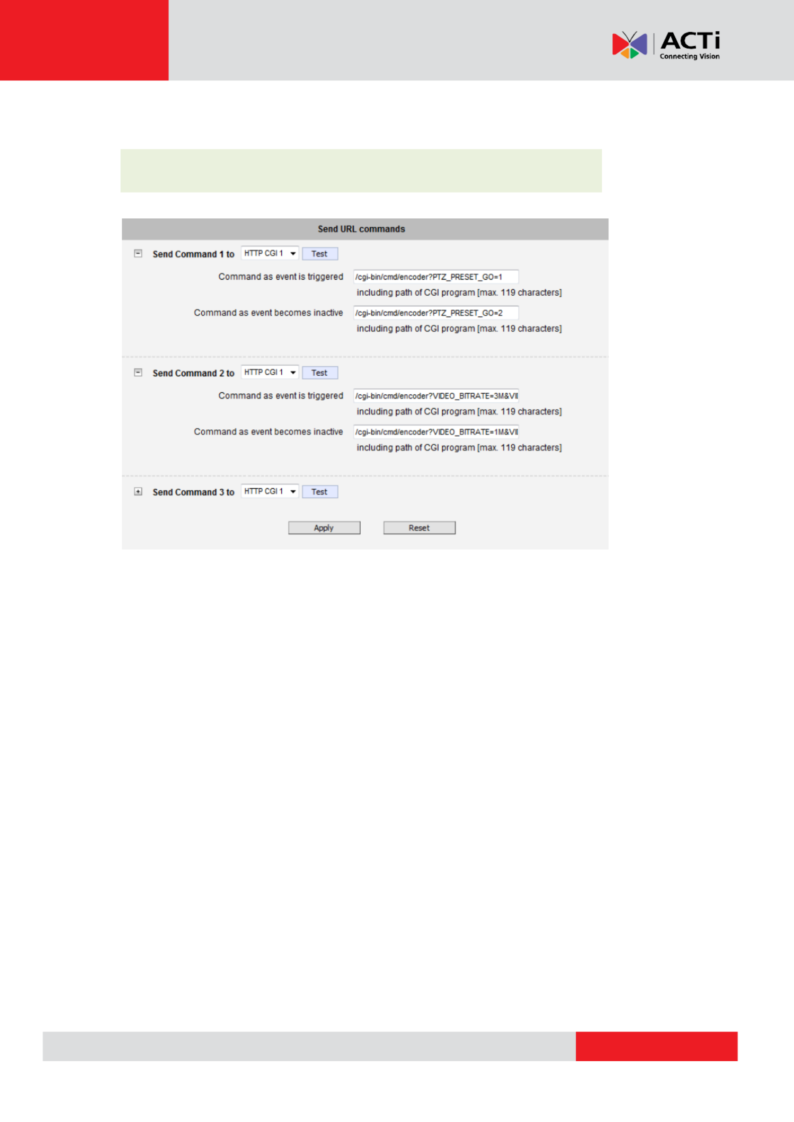
www.acti.com
Firmware User
Firmware User
Firmware User
Firmware UserFirmware User’
’
’
’’s Manual V6.03
s Manual V6.03
s Manual V6.03
s Manual V6.03s Manual V6.03 3
3
3
3 3
.0
.0
.0
.0.0
65
*Pre-requisites: HTTP CGI server setup.
Send URL commands
URL commands can be sent to HTTP CGI servers upon event. This provides the possibility of
highly intelligent response upon event. IP devices and many other devices also have embedded
CGI servers may be controlled. that
When Event Handler sends an command, it will send one set of command when the event is URL
trigged, and another as the event becomes inactive. Depending on the CGI design, the URL
commands may be able to be stringed together, and multiple commands may be issued in a
single line.
An example would be when the access control device at the entrance detects an entry, this device
provides a DI signal to the PTZ camera, and triggers an event. This event then sends a loopback
command to the PTZ Camera itself (by setting its own IP as the HTTP CGI server). The PTZ
Camera then moves to a preset location, stays until the event is over, and then moves back to
another location. At the same time it moves to the pre-set location, it increases the bitrate from
1M to 3M, and the frame rate from 4 fps to 8 fps. The bitrate / fps changes are reverted at the end
of event.
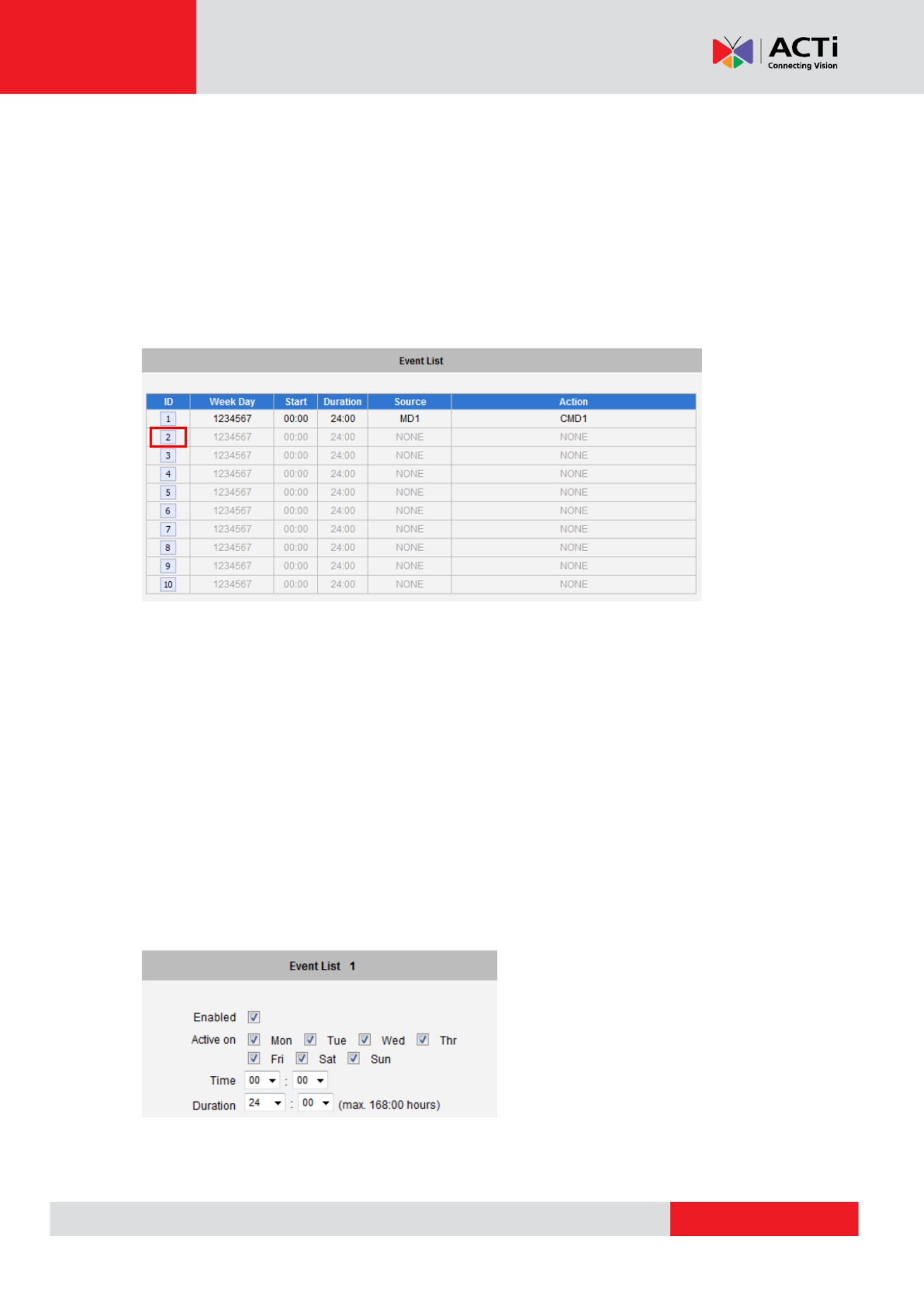
www.acti.com
Firmware User
Firmware User
Firmware User
Firmware UserFirmware User’
’
’
’’s Manual V6.03
s Manual V6.03
s Manual V6.03
s Manual V6.03s Manual V6.03 3
3
3
3 3
.0
.0
.0
.0.0
66
Event List
You may define a maximum of 10 Event rules, which will be shown in abbreviated form in the
Event List panel. It will display under each Event ID, the days of the week it will be active, the start
time and duration of the active period, the type of the source of trigger, and the actions used in
the response. If the row is grayed out, this means the rule is currently not enabled and stays
inactive.
You may start creating a new event by clicking the event ID number in the list, for example 2 . “ ”
There are several parts to the Event rule:
When is it active?
You may choose to enable the rule or not. The settings will be kept in internal memory even if the
event rule is disabled. lect the days in a weekly cycle in which this rule and schedule is active. Se
Determine the start time and duration of the active period. For example, a rule that lets motion
detection trigger snapshot uploads to FTP would only take place after 19:00 each day for 12
hours. Outside of this time the rule will not be active.
In the example below, the event handler rule is active 24 hours a day, 7 days a week.

www.acti.com
Firmware User
Firmware User
Firmware User
Firmware UserFirmware User’
’
’
’’s Manual V6.03
s Manual V6.03
s Manual V6.03
s Manual V6.03s Manual V6.03 3
3
3
3 3
.0
.0
.0
.0.0
67
How is it triggered?
Events may be triggered by one of the several sources. In the example below, Motion Detection
region 1 is used as the event trigger.
You may also ask the event to be repeatedly triggered during this scheduled time. The interval is
determined in minutes. You may use this with email / FTP upload to take snapshots at regular
intervals.
DIs: For selected models only, the IP device may be triggered by Digital Input.
Motion: You may trigger the event if one or many Motion Detection regions encounter a motion
trigger. Trigger from any of them will initiate the event. The duration of event will be the same as
the MD trigger length, or the Trigger interval time, defined in the Motion Detection section on
Video Adjust page.
Video Loss: This is available for video servers only. When the analog video in is lost, the video
state will become lost , and return to normal“ ” “ ” only until device receives analog video signal. A
common scenario is for Video Server to send email to administrator when video is lost, and
activate DO signal to alarm that persists until the analog signal is restored.
Switch to Night mode: This is available to selected models only. When camera changes
between day and night modes, the embedded event handler will notice this change, and may act
upon this information.
Potential uses include changing the motion detection profile to another set of Event MD
parameters. By having two sets of parameters each optimized for day and night, this provide
better overall accuracy in both day and night conditions. Some night time only MD regions may
also be activated this way. The event period will end when the camera returns to day mode, which
will then reset the camera to the original settings.
Device boots successfully: This will trigger the event responses once the device boots up. You
can use this to create a notification system that keeps record of when the device has been
rebooted via email.

www.acti.com
Firmware User
Firmware User
Firmware User
Firmware UserFirmware User’
’
’
’’s Manual V6.03
s Manual V6.03
s Manual V6.03
s Manual V6.03s Manual V6.03 3
3
3
3 3
.0
.0
.0
.0.0
68
Reboot device: This triggers the event response when the device is shut down via web UI Save “
and Reboot . Use this to keep record of when was the device setting edited. Note that this will not ”
take effect when the device is unplugged, as this is not normal shutdown.
What responses will occur?
Digital Output elected models only): This is a useful link to other devices. Click to include this in (s
the response for this rule.
Send notification Message: Select from the three pre-defined messages which you ve setup in ’
the Event Configuration section. You may enable multiple messages at the same time. For
sending Email, please limit the recipient to one per event rule. If you need to send email to more
than one recipient, please use separate event rules triggered by the same trigger.
Upload video/snapshots: Select which of the event configurations to include in this response set.
If you are sending email via upload video and sending notification message at the same time, the
system will automatically merge the two emails into one. The subject and image will be based
upon the Upload snapshot Event configuration enabled, but the message in the body text will be
based upon the Notification messages.
In general, please stick to the one email per event rule limit for best performance. “ ”
Change Motion Detection profile: This will switch the profile of the selected Motion Detection
region from Runtime profile to Event profile. The profile will return to runtime settings at the end of
this event. You may program one motion detection region to be disabled at runtime, but enable it
with event handler under some circumstances.
Send URL command: Select the URL command to include in the response set. Two different
commands will be sent at the time when the event is triggered and un- iggered. tr
Change to Night Mode (Selected models only): For some models, you may force the Camera
into Night mode. The camera will return to its previous setting (whether auto or forced day/ night)
upon the end of the event.

www.acti.com
Firmware User
Firmware User
Firmware User
Firmware UserFirmware User’
’
’
’’s Manual V6.03
s Manual V6.03
s Manual V6.03
s Manual V6.03s Manual V6.03 3
3
3
3 3
.0
.0
.0
.0.0
70
Syste
Syste
Syste
SysteSystem
m
m
m m
The section ovides list of functions that help manage the System pr the
camera. The [+] mark before System indicates that the list can be expanded by clicking on it.
Once expanded, the list can later be collapsed again by clicking on the [-] mark.
User Account
The section User Accounts allows doing following user management
tasks:
1. Change the account name or password of the Root account that has a full access to the
camera.
2. Create up to 10 common users that only have an access for live view and PTZ control.
3. Enable/disable the option of seeing the live view without needing user name and password
(anonymous login), which is especially convenient function for camera installers on the field.
For security reasons, account name and password is always required when entering Setup
page of Web Configurator or when trying to access camera or change settings by URL
commands.
After changing any of the items above, press to save the changes. The Reset button Apply
undoes the changes that had just been made but not Applied yet.

www.acti.com
Firmware User
Firmware User
Firmware User
Firmware UserFirmware User’
’
’
’’s Manual V6.03
s Manual V6.03
s Manual V6.03
s Manual V6.03s Manual V6.03 3
3
3
3 3
.0
.0
.0
.0.0
71
System Info
The section provides the full information about camera System Info
status, settings and log. This information is very helpful while doing the camera configuration,
maintenance or troubleshooting.
The is a convenient way of exporting the full list of camera related information in a Server Report
text format, so that it can be sent to the technical support team for faster service.

www.acti.com
Firmware User
Firmware User
Firmware User
Firmware UserFirmware User’
’
’
’’s Manual V6.03
s Manual V6.03
s Manual V6.03
s Manual V6.03s Manual V6.03 3
3
3
3 3
.0
.0
.0
.0.0
72
Factory Default
The section Factory Default allows the camera settings be reset to the
original factory settings.
If you want to keep network settings and restore other settings to factory default, please select the
first option you select the second one instead, all the settings would be removed during factory . If
default. You will have to use factory default IP setting to connect to this camera.
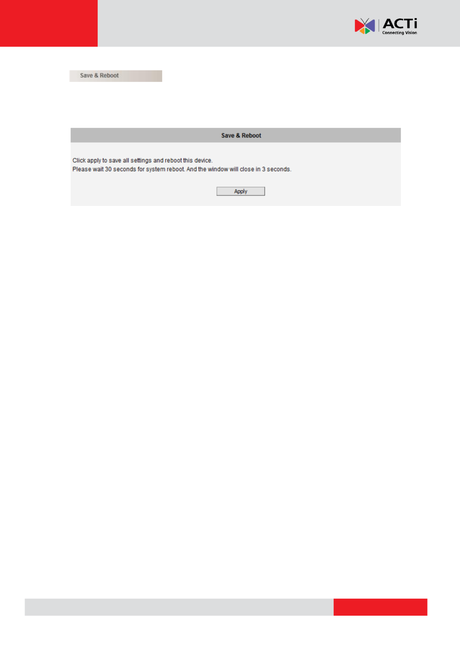
www.acti.com
Firmware User
Firmware User
Firmware User
Firmware UserFirmware User’
’
’
’’s Manual V6.03
s Manual V6.03
s Manual V6.03
s Manual V6.03s Manual V6.03 3
3
3
3 3
.0
.0
.0
.0.0
74
Save & Reboot
The Save & Reboot section allows saving the settings and
rebooting the camera remotely. This is critical because some settings might not take effect before
save & reboot.

www.acti.com
Firmware User
Firmware User
Firmware User
Firmware UserFirmware User’
’
’
’’s Manual V6.03
s Manual V6.03
s Manual V6.03
s Manual V6.03s Manual V6.03 3
3
3
3 3
.0
.0
.0
.0.0
75
Logout
Logout
Logout
Logout Logout
Clicking this item allows you to log out of the IP device. Be sure to logout
this IP device once you have completed all the tasks via Web Configurator.
Produktspezifikationen
| Marke: | ACTi |
| Kategorie: | Überwachungskamera |
| Modell: | E61 |
Brauchst du Hilfe?
Wenn Sie Hilfe mit ACTi E61 benötigen, stellen Sie unten eine Frage und andere Benutzer werden Ihnen antworten
Bedienungsanleitung Überwachungskamera ACTi

29 August 2024
28 August 2024
24 August 2024
24 August 2024
24 August 2024
24 August 2024
21 August 2024
21 August 2024
19 August 2024
18 August 2024
Bedienungsanleitung Überwachungskamera
- Überwachungskamera Samsung
- Überwachungskamera Approx
- Überwachungskamera Belkin
- Überwachungskamera Sanyo
- Überwachungskamera Exibel
- Überwachungskamera Gembird
- Überwachungskamera Genius
- Überwachungskamera Hama
- Überwachungskamera LogiLink
- Überwachungskamera Logitech
- Überwachungskamera Manhattan
- Überwachungskamera Nedis
- Überwachungskamera Niceboy
- Überwachungskamera Philips
- Überwachungskamera Sony
- Überwachungskamera Trust
- Überwachungskamera Panasonic
- Überwachungskamera Clas Ohlson
- Überwachungskamera Profile
- Überwachungskamera ZyXEL
- Überwachungskamera Bosch
- Überwachungskamera Laserliner
- Überwachungskamera Buffalo
- Überwachungskamera Canon
- Überwachungskamera Velleman
- Überwachungskamera Powerfix
- Überwachungskamera Eminent
- Überwachungskamera Linksys
- Überwachungskamera Maginon
- Überwachungskamera Netgear
- Überwachungskamera Technaxx
- Überwachungskamera Alecto
- Überwachungskamera Denver
- Überwachungskamera EMOS
- Überwachungskamera Gira
- Überwachungskamera König
- Überwachungskamera MarQuant
- Überwachungskamera Renkforce
- Überwachungskamera Thomson
- Überwachungskamera Trevi
- Überwachungskamera Blaupunkt
- Überwachungskamera Schneider
- Überwachungskamera Trebs
- Überwachungskamera Pyle
- Überwachungskamera Topcom
- Überwachungskamera Pioneer
- Überwachungskamera JVC
- Überwachungskamera Motorola
- Überwachungskamera Xiaomi
- Überwachungskamera Abus
- Überwachungskamera Avidsen
- Überwachungskamera Elro
- Überwachungskamera EZVIZ
- Überwachungskamera Imou
- Überwachungskamera INSTAR
- Überwachungskamera Megasat
- Überwachungskamera Olympia
- Überwachungskamera Smartwares
- Überwachungskamera Switel
- Überwachungskamera Yale
- Überwachungskamera Ferguson
- Überwachungskamera Orion
- Überwachungskamera Gigaset
- Überwachungskamera Strong
- Überwachungskamera Toshiba
- Überwachungskamera Garmin
- Überwachungskamera Perel
- Überwachungskamera Netis
- Überwachungskamera Lindy
- Überwachungskamera Fenton
- Überwachungskamera Waeco
- Überwachungskamera Acme
- Überwachungskamera Burg Wächter
- Überwachungskamera Marmitek
- Überwachungskamera Marshall
- Überwachungskamera Honeywell
- Überwachungskamera B/R/K
- Überwachungskamera Marshall Electronics
- Überwachungskamera TRENDnet
- Überwachungskamera Targa
- Überwachungskamera First Alert
- Überwachungskamera AVerMedia
- Überwachungskamera Zebra
- Überwachungskamera TP-Link
- Überwachungskamera Flamingo
- Überwachungskamera Kodak
- Überwachungskamera Rollei
- Überwachungskamera IGet
- Überwachungskamera Adj
- Überwachungskamera Netatmo
- Überwachungskamera Duramaxx
- Überwachungskamera Ebode
- Überwachungskamera Xavax
- Überwachungskamera InFocus
- Überwachungskamera Overmax
- Überwachungskamera Monoprice
- Überwachungskamera Monacor
- Überwachungskamera JUNG
- Überwachungskamera Ednet
- Überwachungskamera AG Neovo
- Überwachungskamera Nest
- Überwachungskamera Edimax
- Überwachungskamera V-TAC
- Überwachungskamera Aritech
- Überwachungskamera Uniden
- Überwachungskamera Kogan
- Überwachungskamera Genie
- Überwachungskamera M-e
- Überwachungskamera Elmo
- Überwachungskamera Lumens
- Überwachungskamera Jablocom
- Überwachungskamera Conceptronic
- Überwachungskamera D-Link
- Überwachungskamera Eufy
- Überwachungskamera Stabo
- Überwachungskamera Friedland
- Überwachungskamera EVOLVEO
- Überwachungskamera SPC
- Überwachungskamera August
- Überwachungskamera Ring
- Überwachungskamera Digitus
- Überwachungskamera SereneLife
- Überwachungskamera Swann
- Überwachungskamera Vitek
- Überwachungskamera DataVideo
- Überwachungskamera LevelOne
- Überwachungskamera Aida
- Überwachungskamera APC
- Überwachungskamera Beafon
- Überwachungskamera Chuango
- Überwachungskamera Cisco
- Überwachungskamera Grandstream
- Überwachungskamera Delta Dore
- Überwachungskamera EVE
- Überwachungskamera Defender
- Überwachungskamera Tenda
- Überwachungskamera Swisstone
- Überwachungskamera Foscam
- Überwachungskamera Ubiquiti Networks
- Überwachungskamera Kramer
- Überwachungskamera Vaddio
- Überwachungskamera Intellinet
- Überwachungskamera Reolink
- Überwachungskamera Swan
- Überwachungskamera Hikvision
- Überwachungskamera FLIR
- Überwachungskamera Furrion
- Überwachungskamera Arlo
- Überwachungskamera Nexxt
- Überwachungskamera Planet
- Überwachungskamera EnGenius
- Überwachungskamera Dörr
- Überwachungskamera Lorex
- Überwachungskamera Ikan
- Überwachungskamera Comtrend
- Überwachungskamera Somfy
- Überwachungskamera Dahua
- Überwachungskamera Dedicated Micros
- Überwachungskamera DIO
- Überwachungskamera EasyN
- Überwachungskamera Escam
- Überwachungskamera EverFocus
- Überwachungskamera Ganz
- Überwachungskamera GeoVision
- Überwachungskamera Hombli
- Überwachungskamera Home Protector
- Überwachungskamera Iiquu
- Überwachungskamera Indexa
- Überwachungskamera Interlogix
- Überwachungskamera KlikaanKlikuit
- Überwachungskamera Kompernass
- Überwachungskamera Mr Safe
- Überwachungskamera Naxa
- Überwachungskamera Nordval
- Überwachungskamera Notifier
- Überwachungskamera Oplink
- Überwachungskamera Provision ISR
- Überwachungskamera Quantum
- Überwachungskamera Raymarine
- Überwachungskamera Revo
- Überwachungskamera SAB
- Überwachungskamera Satel
- Überwachungskamera SecurityMan
- Überwachungskamera Sinji
- Überwachungskamera SMC
- Überwachungskamera Sonic Alert
- Überwachungskamera Sricam
- Überwachungskamera Steren
- Überwachungskamera Storage Options
- Überwachungskamera Tenvis
- Überwachungskamera Hive
- Überwachungskamera Ubiquiti
- Überwachungskamera Vivotek
- Überwachungskamera Woonveilig
- Überwachungskamera Y-cam
- Überwachungskamera AVer
- Überwachungskamera Epcom
- Überwachungskamera ZKTeco
- Überwachungskamera AirLive
- Überwachungskamera Mobotix
- Überwachungskamera Dahua Technology
- Überwachungskamera Speco Technologies
- Überwachungskamera 3xLOGIC
- Überwachungskamera Atlantis Land
- Überwachungskamera CRUX
- Überwachungskamera Pentatech
- Überwachungskamera Summer Infant
- Überwachungskamera Illustra
- Überwachungskamera Surveon
- Überwachungskamera Avigilon
- Überwachungskamera Brilliant
- Überwachungskamera Hanwha
- Überwachungskamera Lanberg
- Überwachungskamera Verint
- Überwachungskamera Axis
- Überwachungskamera EtiamPro
- Überwachungskamera MEE Audio
- Überwachungskamera Advantech
- Überwachungskamera Chacon
- Überwachungskamera Alula
- Überwachungskamera EKO
- Überwachungskamera IOIO
- Überwachungskamera KJB Security Products
- Überwachungskamera BZBGear
- Überwachungskamera Adesso
- Überwachungskamera Brickcom
- Überwachungskamera Insteon
- Überwachungskamera Aigis
- Überwachungskamera Pelco
- Überwachungskamera ORNO
- Überwachungskamera Atlona
- Überwachungskamera Linear PRO Access
- Überwachungskamera Laxihub
- Überwachungskamera Valueline
- Überwachungskamera Aqara
- Überwachungskamera Tecno
- Überwachungskamera Lutec
- Überwachungskamera Brinno
- Überwachungskamera Night Owl
- Überwachungskamera WyreStorm
- Überwachungskamera Exacq
- Überwachungskamera Equip
- Überwachungskamera AVMATRIX
- Überwachungskamera UniView
- Überwachungskamera Alfatron
- Überwachungskamera Syscom
- Überwachungskamera BLOW
- Überwachungskamera Videotec
- Überwachungskamera DSC
- Überwachungskamera AViPAS
- Überwachungskamera Milestone Systems
- Überwachungskamera Inkovideo
- Überwachungskamera Hamlet
- Überwachungskamera Mobi
- Überwachungskamera Infortrend
- Überwachungskamera VideoComm
- Überwachungskamera Kguard
- Überwachungskamera Boyo
- Überwachungskamera HiLook
- Überwachungskamera Mach Power
- Überwachungskamera Canyon
- Überwachungskamera Digital Watchdog
- Überwachungskamera Ernitec
- Überwachungskamera Ikegami
- Überwachungskamera Gewiss
- Überwachungskamera Weldex
- Überwachungskamera Costar
- Überwachungskamera Sentry360
- Überwachungskamera ALC
- Überwachungskamera Spyclops
- Überwachungskamera Compro
- Überwachungskamera IDIS
- Überwachungskamera I3International
- Überwachungskamera B & S Technology
- Überwachungskamera Qian
- Überwachungskamera Accsoon
- Überwachungskamera Control4
- Überwachungskamera Petcube
- Überwachungskamera Apeman
- Überwachungskamera ATN
- Überwachungskamera IC Intracom
- Überwachungskamera POSline
- Überwachungskamera Watec
- Überwachungskamera ETiger
- Überwachungskamera Videcon
- Überwachungskamera BirdDog
- Überwachungskamera Topica
- Überwachungskamera Rostra
- Überwachungskamera Caddx
- Überwachungskamera Whistler
- Überwachungskamera ClearView
- Überwachungskamera Beseye
- Überwachungskamera IMILAB
- Überwachungskamera CNB Technology
- Überwachungskamera Tapo
- Überwachungskamera Securetech
- Überwachungskamera NetMedia
- Überwachungskamera Nivian
- Überwachungskamera Guardzilla
- Überwachungskamera Blink
- Überwachungskamera Zavio
- Überwachungskamera Campark
- Überwachungskamera IPX
- Überwachungskamera Annke
- Überwachungskamera AVTech
- Überwachungskamera Vimtag
- Überwachungskamera Security Labs
- Überwachungskamera Seneca
- Überwachungskamera Vosker
- Überwachungskamera Owltron
- Überwachungskamera Enabot
- Überwachungskamera Luis Energy
- Überwachungskamera Sir Gawain
- Überwachungskamera VisorTech
- Überwachungskamera Milesight
- Überwachungskamera GVI Security
- Überwachungskamera Conbrov
- Überwachungskamera HuddleCamHD
- Überwachungskamera Setti+
- Überwachungskamera BIRDFY
- Überwachungskamera I-PRO
- Überwachungskamera DVDO
- Überwachungskamera TCP
Neueste Bedienungsanleitung für -Kategorien-
15 Oktober 2024

15 Oktober 2024
14 Oktober 2024
14 Oktober 2024

13 Oktober 2024
13 Oktober 2024
13 Oktober 2024
11 Oktober 2024
11 Oktober 2024
11 Oktober 2024