ZKTeco Z3104/08 XER-C Bedienungsanleitung
ZKTeco
Sicherheitskamera
Z3104/08 XER-C
Lesen Sie kostenlos die 📖 deutsche Bedienungsanleitung für ZKTeco Z3104/08 XER-C (114 Seiten) in der Kategorie Sicherheitskamera. Dieser Bedienungsanleitung war für 17 Personen hilfreich und wurde von 2 Benutzern mit durchschnittlich 4.5 Sternen bewertet
Seite 1/114

User Manual
Video Recorder
Version: 2017.11

1
1 Important Tips and Warnings
Electrical safety
Installation and operation should conform to your local electrical safety codes. We assume no liability or
responsibility for any fires or electrical shock caused by improper handling or installation.
Transportation security
Heavy stress, violent vibration or water splash should be avoided during transportation, storage and installation.
Installation
Keep upright. Handle with care.
Do not apply power to the NVR before completing installation.
Do not place objects on top of the NVR
Qualified engineers needed
All examination and repair work should be done by qualified service engineers.
We are not liable for any problems caused by unauthorized modifications or attempted repair.
Environment
The NVR should be installed in a cool, dry place away from direct sunlight and inflammable or explosive substances,
etc.
This product should be transported, stored and operated in the specified environments.
Accessories
Be sure to use all the accessories available in the package.
Before installation, please open the package and check all the components are included.
Contact your local retailer if something is broken or missing in your package.
Lithium battery
Improper battery use may result in fire, explosion, or personal injury.
When replacing the battery, please make sure you use the same model.

2
2 Declaration
Please prevail in kind. The manual is for reference only.
This manual may contain inaccurate data or printing error.
The products described in this manual may be updated at any time.
Screenshots of the manual is not in a machine and only for display.
If in doubt, obtaining a copy of the latest procedure or the additional document, please contact with the
company's after- sales department.

3
C ontents
1 Important Tips and Warnings ................................................................................................................................................................................................. 1
2 Declaration ......................................................................................................................................................................................................................................... 2
3 Product Introduction ................................................................................................................................................................................................................... 1
3.1 Product Overview .......................................................................................................................................................................................................... 1
3.2 Feature ................................................................................................................................................................................................................................... 1
4 Read First .............................................................................................................................................................................................................................................. 3
4.1 Front Panel .......................................................................................................................................................................................................................... 3
4.2 Remote Control ............................................................................................................................................................................................................... 4
4.3 The Mouse ........................................................................................................................................................................................................................... 7
4.4 The Input Method .......................................................................................................................................................................................................... 8
4.5 Icon .......................................................................................................................................................................................................................................... 9
4.5.1 The Screen Icons .................................................................................................................................................................................................. 9
4.5.2 Operation Icons ................................................................................................................................................................................................... 9
5 Installation ........................................................................................................................................................................................................................................ 10
5.1 Unpacking Inspection .............................................................................................................................................................................................. 10
5.2 HDD Installation ........................................................................................................................................................................................................... 10
5.3 Installation of the burner ........................................................................................................................................................................................ 10
5.4 Alarm/PTZ/Control Keyboard Interface ........................................................................................................................................................ 11
5.5 POE Connection ........................................................................................................................................................................................................... 13
6 Basic Operations Guide ........................................................................................................................................................................................................... 14
6.1 Power On and Off ........................................................................................................................................................................................................ 14
6.1.1 Power On ............................................................................................................................................................................................................... 14
6.1.2 Power Off (Shutdown) .................................................................................................................................................................................. 14
6.1.3 Restart ..................................................................................................................................................................................................................... 14
6.1.4 Power recovery .................................................................................................................................................................................................. 15
6.2 Start - up Wizard.............................................................................................................................................................................................................. 15
6.3 Add Camera .................................................................................................................................................................................................................... 17
6.3.1 Mode Switch ....................................................................................................................................................................................................... 17
6.3.2 QUICK ADD IP CAMERA ................................................................................................................................................................................ 18
6.3.3 IP Channel Management ............................................................................................................................................................................ 20
6.3.4 Add IP Cameras ................................................................................................................................................................................................. 21
6.3.5 Modify channel configuration ................................................................................................................................................................. 22
6.3.6 Configure Front Device ................................................................................................................................................................................ 22
6.3.7 Delete Front- end Device............................................................................................................................................................................. 27
6.3.8 Advanced Setting ............................................................................................................................................................................................ 27
6.4 The Event of Configuration ................................................................................................................................................................................... 28
6.4.1 Video Detection Configuration .............................................................................................................................................................. 29
6.4.2 Intelligent Analysis .......................................................................................................................................................................................... 30
6.4.3 Alarm Configuration ...................................................................................................................................................................................... 33
6.4.4 Abnormal Alarm ............................................................................................................................................................................................... 34
6.5 Log in/Log out ............................................................................................................................................................................................................... 35

4
6.6 Preview ............................................................................................................................................................................................................................... 36
6.6.1 Live Preview ......................................................................................................................................................................................................... 36
6.6.2 Channel Toolbar ................................................................................................................................................................................................ 37
6.6.3 Right Click Menu .............................................................................................................................................................................................. 38
6.6.4 Task Bar ................................................................................................................................................................................................................... 41
6.7 Search .................................................................................................................................................................................................................................. 44
6.7.1 Search ...................................................................................................................................................................................................................... 44
6.7.2 Event Search ........................................................................................................................................................................................................ 48
6.7.3 Tag Search ............................................................................................................................................................................................................ 49
6.7.4 Smart Search ....................................................................................................................................................................................................... 50
6.7.5 External Search .................................................................................................................................................................................................. 51
6.7.6 Face search ........................................................................................................................................................................................................... 52
6.8 Record Backup ............................................................................................................................................................................................................... 53
7 Local Configuration .................................................................................................................................................................................................................... 55
7.1 The Introduction of The Main Menu ............................................................................................................................................................... 55
7.2 INFO ...................................................................................................................................................................................................................................... 56
7.2.1 System ..................................................................................................................................................................................................................... 56
7.2.2 Event ........................................................................................................................................................................................................................ 57
7.2.3 Net Information ................................................................................................................................................................................................ 58
7.2.4 LOG ............................................................................................................................................................................................................................ 59
7.3 CONFIG ............................................................................................................................................................................................................................... 60
7.3.1 Channel Setting ................................................................................................................................................................................................ 60
7.3.2 Network .................................................................................................................................................................................................................. 63
7.3.3 Event ........................................................................................................................................................................................................................ 70
7.3.4 Storage .................................................................................................................................................................................................................... 70
7.3.5 System Configuration ................................................................................................................................................................................... 73
7.3.6 APP Center............................................................................................................................................................................................................ 79
8 WEB Access ...................................................................................................................................................................................................................................... 85
8.1 WEB Operation .............................................................................................................................................................................................................. 85
8.1.1 Network Connection ..................................................................................................................................................................................... 85
8.1.2 The control installation and the user login logout .................................................................................................................... 85
8.1.3 The Interface of Web Operations .......................................................................................................................................................... 86
8.1.4 Configuration ..................................................................................................................................................................................................... 90
8.1.5 Search Record .................................................................................................................................................................................................... 91
8.1.6 Alarm Configuration ...................................................................................................................................................................................... 92
9 Appendix .......................................................................................................................................................................................................................................... 94
9.1 Alarm linkage setting ................................................................................................................................................................................................ 94
9.1.1 Alarm Out .............................................................................................................................................................................................................. 94
9.1.2 Linkage Record .................................................................................................................................................................................................. 94
9.1.3 Snapshot ................................................................................................................................................................................................................ 95
9.1.4 PTZ Linkage ......................................................................................................................................................................................................... 95
9.1.5 Tour ........................................................................................................................................................................................................................... 95
9.1.6 Show Message ................................................................................................................................................................................................... 95
9.1.7 Buzzer ...................................................................................................................................................................................................................... 96

5
9.1.8 Send Email ............................................................................................................................................................................................................ 96
9.1.9 Server Push .......................................................................................................................................................................................................... 97
9.1.10 Send NetDisk ................................................................................................................................................................................................... 97
9.2 Port Mapping ................................................................................................................................................................................................................. 98
9.2.1 ................................................................................................................................................................................................... UPNP Function 98
9.2.2 Port mapping Manually ............................................................................................................................................................................... 99
9.3 Voice Intercom ........................................................................................................................................................................................................... 100
9.3.1 Summarize ........................................................................................................................................................................................................ 100
9.3.2 Configuration .................................................................................................................................................................................................. 100
9.4 HDD S.M.A.R.T ............................................................................................................................................................................................................. 100
9.5 Hard disk problem .................................................................................................................................................................................................... 102
9.6 HDD Capacity Calculation .................................................................................................................................................................................. 104
9.7 Terms ................................................................................................................................................................................................................................ 105
9.8 FAQ ..................................................................................................................................................................................................................................... 106

3 Product Introduction
3.1 Product Overview
This series DVR/NVR is a high performance network video recorder, combined with H.264 video compression,
high-capacity hard disk storage, TCP / IP transmission, embedded Linux operating system and a variety of other
advanced technologies in the electronic information industry, all those ensure that a high-quality, low bit rate video
storage characteristics, and good system stability.
This product complies with GB 20815-2006 standard video security surveillance digital video recording
promulgated by the State. At the same time, the product supports the ONVIF protocol” base on’ ONVIF ™ Core
Specification’ Version 2.2” and is compatible with the network cameras which supports ONVIF protocol.
Some of the products can enable the switching between the NVR mode and Hybrid mode “Hybrid mode supports
both analog cameras and network cameras, NVR mode only supports network cameras”. This series product
support local preview, multiple window display, recorded file local storage, remote control and mouse shortcut -
menu operation, and remote management and control function. recording, playback, monitoring, synchronization
of audio and video. Besides, the products support advanced control technology and strong network data
transmission capacity.
3.2 Feature
Real-time monitoring
Have a composite video signal interface and support TV, VGA or HDMI output simultaneously.
Compression function
Use H.264 video compression standard and G.711 audio compression standard and have high definition, low code
rate of the video coding and the storage.
Recording function
Support timing, linkage alarm, motion detection, SATA hard and local hard disk , DVR data backup and network
backup.
Video playback function
Achieve searching videos by a variety of conditions, playback in local and network. Support multiple videos
playback, fast playing, slow playing and frame- -by frame playback. Video playback can display the exact time of the

2
incident. Provide time line retrieving page for quick searching.-
Camera control and alarm
Be controlled by the remote camera and equip many alarm input interfaces. Be connected to various types of
alarm devices. Dynamic detection, video loss, video block, multiple alarm output and scene lighting control can be
realized.
Communication Interface
Equip USB 2.0 high-speed interface or ESATA interface and allow many backup devices. Equip standard Ethernet
interface. Plug and play in a variety of network conditions,
Network functions
Support TCP / IP, UDP, RTP / RTSP, DHCP, PPPOE, DDNS, NTP P2P etc. Support real-time network monitoring, video
playback, control and management functions; built-in WEB Server, you can directly access through a browser.
Operation Mode
Support various shortcut menu operation modes, on the front panel, remote control, mouse, etc.;Support simple
and intuitive GUI。
Intelligent analysis
Support One or Two channel Intelligent Video Analysis, as Face detection and perimeter analysis, Intelligent ,such
linkage pictures storage, videos, external alarm
Intelligent Search
Data can be retrieved through the intelligent analysis of data. Such as face detection data to achieve through face
image search, or by perimeter realization event video analysis data retrieval。
Channel Switch
The simulating device compatible with IP channel by the TVR channel switch.

3
4 Read First
4.1 Front Panel
No Icon Function Name
1 Power Power Power button, press this button to boot up or shut down DVR/NVR.
2 Shift Shift
1. In input Box, switch input methods;
2. Switch TAB;
3 Number Key 1~9
1. Number Input(in number mode);
2. English character Input(in English mode);
3. Switch channel (in 1- ch mode).
4 Input number more
than 10 +10
Enter a digital larger than 10, press two- digit number:
1. Press the tens digit;
2. Press digital switch button;
3. Press ones digit.
5 Up/Down ↑↓
1.Assistant function such as PTZ menu;
2.In monitor mode, switch between multiple- - window and one window;
3. Activate the digital input box increase or decrease the number;
4.Active pull-down menu to switch the drop- down box options;
5. Activate checkbox to change status;
6. Activate the text input box and step down carry and abdication;
7. Activate the control box to move the slider;
8. Activate display window to select the previous channel, next channel.
6 Left/Right ←- 1. Shift current activated control, and then move left and right;
2. In monitor mode, switch channel.
7 ESC ESC Go to previous menu, or cancel current operation.
8 Enter ENTER
1. Confirm current operation;
2. Go to OK button;
3. Go to menu.
9 Function Key Shortcut function with FN key.

4
10 Auxiliary Fn
1. One-
window monitor mode, click this button to display assistant
function: PTZ control and image color;
2. Detection areas setting(like in motion detection setup), working with Fn
and direction keys to realize setup;
3. In text mode, click it to delete the character before the caret(if there is no
shift on the front panel, it can switch input methods), press this button for
1.5sec to clear all of the characters;
4. In playback mode, switch the full screen;
5. Realize other special functions.
11 Play/Pause ▶
1. Go to SEARCH interface;
2. In PTZ channel: ZOOM+;
3. In normal playback click this button to pause playback;
4. In pause mode, click this button to resume playback.
12 Shuttle(outer ring) In real- time monitor mode it works as left/right direction key.
13 Jog(inner dial) In real- time monitor mode it works as up/down direction key.
4.2 Remote Control
The remote control interface is shown as below:

5
No
.
Icon Name Description
1 田
Multiple-Window
Switch
Switch between multiple- -window and one window.
2 Search Access into the recording search menu.
3 1 9 -- Number Key
1. I nput numbers(in number mode)
2. I nput English character(in English mode)
3. S - witch channel(one window mode)
4. Input the password.
4 Esc ESC
1. Go to previous menu
2. Cancel current operation.
5 -/ -- Digital Switch
Enter a digital larger than 10, press two-digit number:
1. Press the tens digit;

6
2. Press digital switch button;
3. Press ones digit.
6 MENU Confirm/Menu Key
1. Confirm current operation;
2. Go to OK button;
3. Go to menu.
7
▲ Up
1.Assistant function such as PTZ menu;
2.In monitor mode, switch between multiple- - window and one window;
3. Activate the digital input box increase or decrease the number;
4.Active pull-down menu to switch the drop- down box options;
5. Activate checkbox to change status;
6. Activate the text input box and step down carry and abdication;
7. Activate the control box to move the slider;
8. Activate display window to select the previous channel, next channel.
▼ Down
◀ Left 1. Shift current activated control, and then move left and right;
2. In monitor mode, switch channel;
3. Assistant function such as PTZ menu.
▶ Right
8 ADD Remote Address Click it to input device number, so that you can control it.
9 FN Auxiliary Key
1. One-
window monitor mode, click this button to display assistant
function: PTZ control and image color;
2. Detection areas setting(like in motion detection setup), working with
Fn and direction keys to realize setup;
3. In text mode, click it to delete the character before the caret(if there is
no shift on the front panel, it can switch input methods), press this
button for 1.5sec to clear all of the characters;
4. In playback mode, switch the full screen;
5. Realize other special functions.
10 | ◀ Previous record/ Iris-
1. In playback mode, playback the previous video;
2. -.In PTZ mode, Iris
11 ▶| Next record/Iris+ 1.In playback mode, playback the next video;

7
2. In PTZ mode, Iris+.
12 | ▶Next Frame Playback the next frame (frame by frame)
13 » Fast Playback Various forward speeds and normal speed playback.
14 ● Stop In normal playback click this button to stop playback.
15 ◀/ ‖Reverse/Pause
1 . In normal playback click this button to pause playback;
2 playback.. In pause mode, click this button to reverse
16 ▶/ ‖Play/Pause
1 . In normal playback click this button to pause playback;
2. In pause mode, click this button to resume playback.
The procedures of controlling multiple DVR by remote control:
The DVR ID default is 8. It’s no need to reset it when control one single DVR by the remote control. If you need to
control multiple DVR, do as below:
First activate the remote control: choose controlled DVR, starts successfully, aim the remote control to control the
hard disk video recorder, press the "Add" button, input device ID) between (1 999), then press ENTER to determine -
can control the corresponding number of hard disk video recorder.
4.3 The Mouse
In addition to front panel keys and remote control menu, the user can use a to control. Insert the mouse interface
into the USB interface.
Left Click
Left click to enter the right menu or the main interface.
Left click to access the menu option.
Perform the operations instructions of the control.
Change the state of the checkbox or dynamic detection blocks.
Pop up a drop down list when left click.-
In the state of PTZ 3D control, left drag the area to achieve regional enlarging or reducing.See details zoom effect
4.1.2 PTZ control section introduction.
Double Click
Double click to play video.
Double click to make the screen full or exit.

8
Right Click
Right click to pop up the right menu in the real time monitoring screen.-
Exit the current interface without saving.
Turning Wheel
Turn the mouse wheel to change the value in the digital box.
Switch the option of the combination box.
Scroll back and forth to achieve the zoom function of channels and PTZ 3D.
Mouse Move
Select controls of the current coordinates to move.
Mouse Drag
Select area to detect.
Select area to shelter.
Select zooming function of PTZ control.
4.4 The Input Method
capitalization and the input of Chinese. Click the mouse to complete the input.” “represents the backspace and ←
“_ “represents a space.
In the input box, you can select figures, symbols, English The input interface of English:
:
:
::
figures:
:
:
::
The input interface of Chinese:
:
:
::

9
4.5 Icon
4.5.1 The Screen Icons
:The channel is recording.
:The video of the channel is lost.
:Motion detection occurs.
:The channel is in monitoring and locked status.
:Adjust the size of the logo of the local audio output.
:Allow screens to round of the Tour.
4.5.2 Operation Icons
:Not selected.
:Be selected.
:The drop - down button
:Leave the interface.
:Cancel the settings.
:Set parameters.
:Save parameters.
:Restore the factory settings.
:Apply current settings to the system.
:Copy current settings to other channels.
:Enter the configuration interface.

10
:Select and configure the processing operation triggered by video detection or alarm.
5 Installation
5.1 Unpacking Inspection
When you receive the product, check according to the packing list in the box.
5.2 HDD Installation
Installation Preparation
Prepare a Cross Screwdriver.
Note: HDD quantity by each model’s specifications shall be final, HDD capacity up to 64 TB.
Steps
Remove the metal top cover by removing two screws from the sides of the cover.
Place the hard disks on a flat table and tighten the screws.
Connect the power and the data lines to the HDD.
Reinstall the metal top cover and tighten the screws.
Caution
Only use the HDD specified by the manufacturer.
The HDD will be formatted automatically during booting and it may cause data loss.
The total duration of video data saved is decided by the HDD’s capability and the DVR’s parameters (recording
setup, encoding setup). Please refer to the form in chapter 11.5.
5.3 Installation of the burner
Installation Preparation
Prepare a Cross Screwdriver.
Steps
Unscrew the screw on the side of the chassis and open the case cover.
Use a screwdriver to remove the bracket fixed in middle of the disk.

11
Open the front panel door and remove the baffle inside.
Connect the burner data cable and the power cord.
Fix the chassis cover.
Caution
The installation of the built in burner is only for specific DVR and affects disk space for installation and interfaces.-
5.4 Alarm/PTZ/Control Keyboard Interface
Alarm/PTZ/Control Keyboard Interface
2 4 6 8
2
4
10 12 14 16
1 3 5 7
1
3
B A 9 11 13 15
UP
DOWN
1 3 2 4 1 2
No Instructions Name
1 Alarm Input
Connect the positive end (+) of the alarm input device to the
alarm input port (ALARM IN 1~16)
2 GND
Connect the ) of the alarm input device to the negative end (-
ground
3 Alarm Output Connect the alarm device
4 - RS 485
485 communication port. They are used to control devices such
as PTZ. Please parallel connect 120TΩ between A/B cables if
there are too many PTZ decoders
Examples of alarm input connections
The alarm input is the switch quantity input. If the alarm input signal is not switch quantity signal but voltage signal,
Different models support different alarm input ports. Please refer to the specifications sheet for detailed
information.
Slight difference may be found on the alarm port layout.

12
refer to the following connection:
Alarm
Input
Devices
(Power
Output)
NVR
Alarm
Switch
Signal
ALM(+)
ALM(-)
G
In
Relay
Examples of alarm output connections
When the alarm output connect with DC and AC load, please refer to the connection.
NVR
Switch
Signal
Output
G
OUT
DC
DC
Loading
G
OUT
NVR
Switch
Signal
Output
R
e
l
a
y
AC
AC
Loading
See details 7.2.5.
The Connection of the P/T/Z
The A, B interface of the PTZ decoder connect with A and B interfaces of the DVR’s RS-485. 120Ω resistors should be
paralleled in the remote A, B lines to reduce the distortion of the signal if a larger number of PTZs are connected.
See details 7.2.4.
Keyboard
The A, B interface of the Keyboard connect with A and B interfaces of the DVR’s RS-485,[MAIN
MENU]-[CONFIGURATION]-[P/T/Z],Protocol choose KEYBORAD. See below.
13
5.5 POE Connection
Non-safe voltage 48V, please pay attention to electrical safety.Supply the NVR with the 12V DC power.
IP Camera should support the POE.
14
6 Basic Operations Guide
6.1 Power On and Off
6.1.1 Power On
Install the DVR/NVR correctly (as above) and then connect the power. The DVR/NVR LED should light up and the
DVR/NVR will boot automatically.
The DVR/NVR will then automatically detect any connected hardware (cameras, monitors, etc.), this process should
last about 30 Seconds. When this process has been completed the DVR/NVR will enter the multi screen real- -time
surveillance mode.
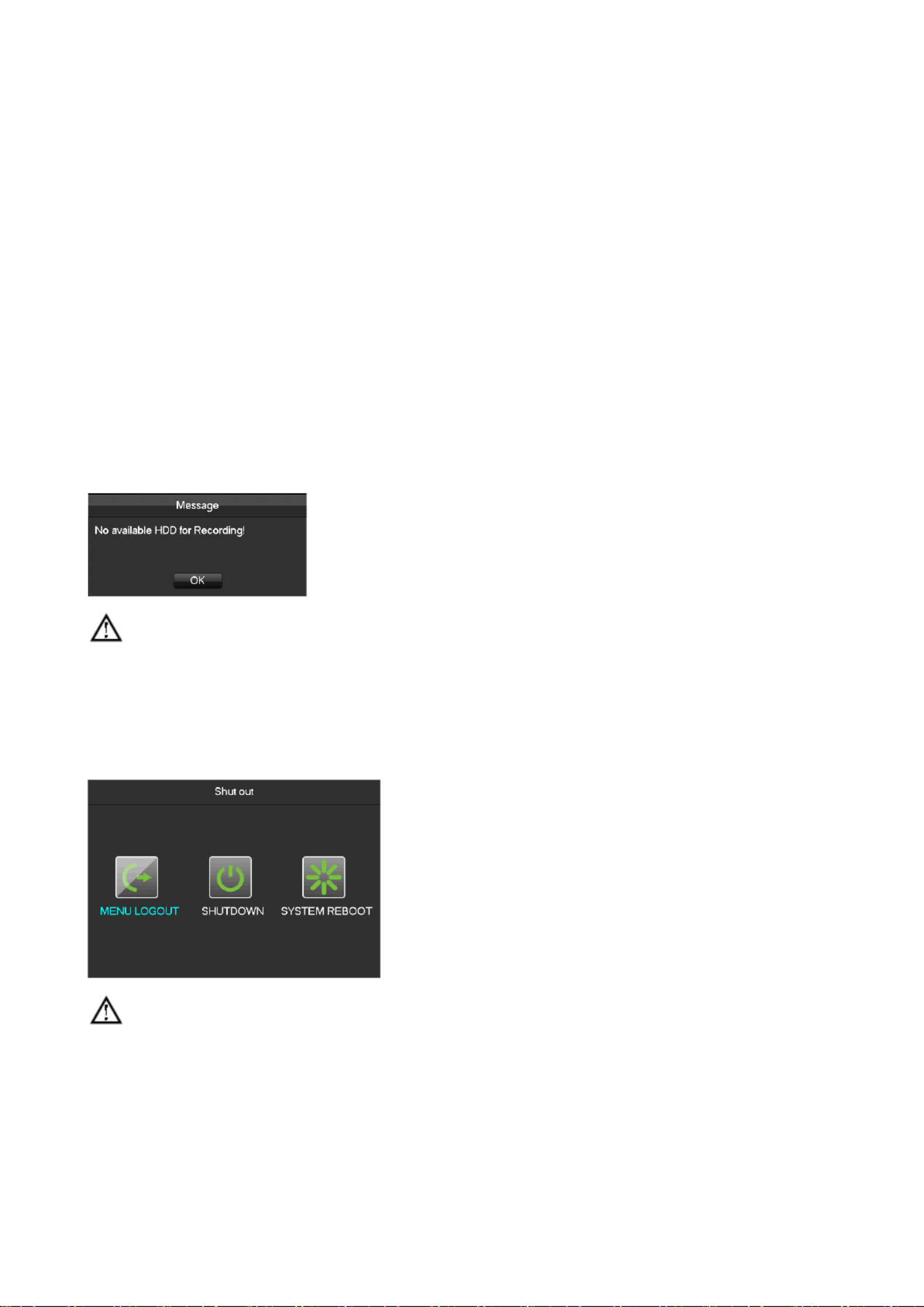
If your hard drive is not properly connected, the following message will appear on your screen.
Note:Please do not use any type of power supply which is different from the power supply included in this kit.
6.1.2 Power Off (Shutdown)
Right mouse click - - [Main Menu] [Shutdown]
Note: Only change or attempt to reconnect the hard disk drive after shutting down the DVR/NVR.
6.1.3 Restart
Right mouse click - - - [Main Menu] [Shutdown] [Restart system]

15
6.1.4 Power recovery
Reboot after an outage or forceful shutdown, DVR will save the record before outage and return to the normal
operation mode.
6.2 Start izard - Wup
Quick configuration P2P account includ es & password setting, network configuration, intelligent mode selection.
Help Information
[QR code] From left to right: Web access address, Android APP address, iPhone APP address.
[Network Connection Status] The current network status.
[ ]Log In Account The login account and password, with the correct account and password can enter the menu.
Default account is admin, and password is 123456.
[Start- up wizard] Activate or not when reboot.
Network configuration
[DHCP]Tick DHCP Enable. Once enable the DHCP, IP address, gateway and subnet mask will get automatically, can’t

16
be set.
[IP address]Enter the number or press up to change the IP address and & ( ) down button [Subnet Mask] and
[Gateway].
[AUTO DNS] Enable the [AUTO DNS], DVR will get the DNS from the DNS server, no need to set.
[DNS 1] DNS server IP.
[DNS 2] DNS alternate IP.
[P2P Account Info] Scan it and shows P2P account, login with mobile APP.
[P2P Account] Display the current P2P account and password.
Account
[Add Users] Add a new user.
[Modify User] authorit Modify the user name, groups, ies.
[Add Group] To add a user group, and configure the user group right.
[Modify Group] Modify the permissions belong to Group
[ Modify Password] Modify the Login password
Intelligent mode selection
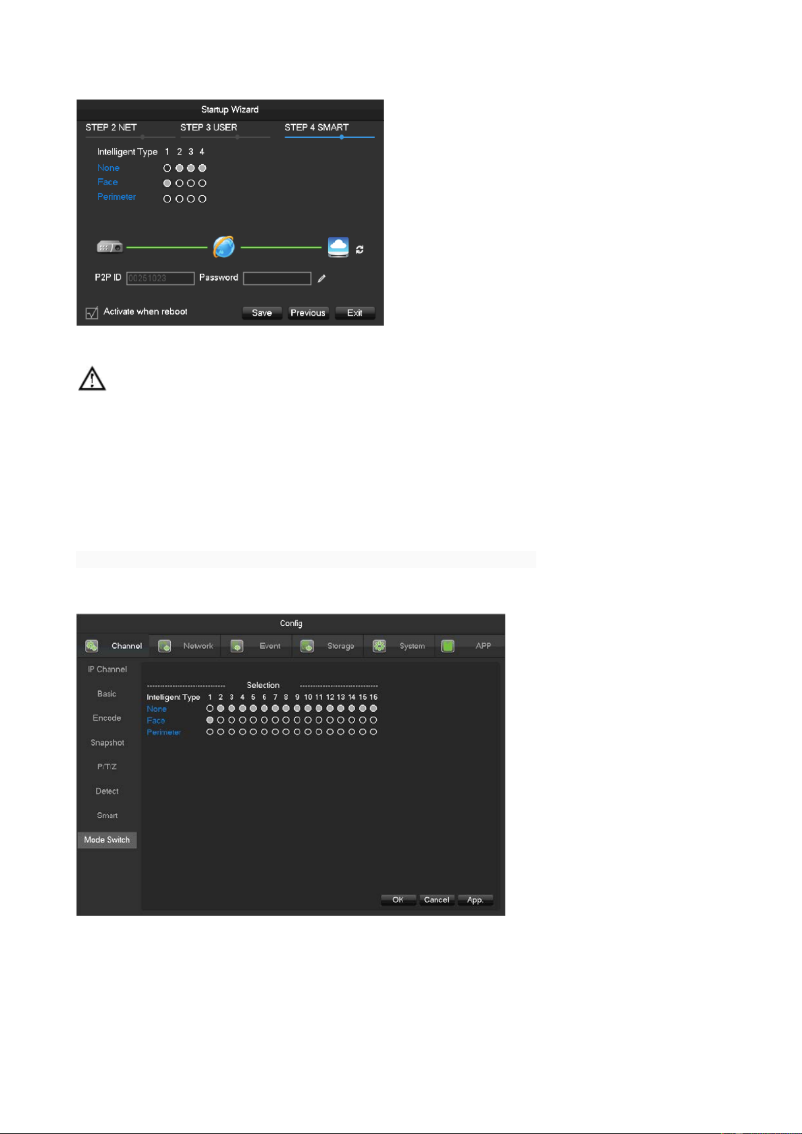
17
[Intelligent mode selection] Intelligent mode selection.
Feature is only available on certain devices. n this section showing the I device’s menu system may differ to
menu system on the device you are using.
6.3 Camera Add
6.3.1 Mode Switch
To TVR, compatib le local channels with net channels by the channel mode switch.
[M Me ]- [C ]- S ain nu hannel [Mode witch] to switch the channel mode.
[ ]IP Cam IP mode, can connect IP camera into the current channel.
[Auto] i Local channel mode, dentify the video standard and resolution automatically.
The default will display the biggest input capacity, the format is “channel No.: resolution/video standard” and will

18
real- time display the current resolution.
The preview screen will display the resolution and video standard once the camera is connected, the format is
“resolution/video standard”, and the display time is 3sec.
Due to the hardware differences, device will prompt wrong information once the connected signal is not
supported.
There are differences to the automatic i feature supporting to the different models. Identify n this section
showing the device’s menu system may differ to menu system on the device you are using.
6.3.2 QUICK ADD IP CAMERA
In preview screen, ove the mouse to the network channel, m it will show "+" sign, left-click to enter the following
menu:

19
Search add
Click [ ] Filter to select the protocol;
C lick [Search] to search devices;
Click “+” to add device.
Manual add
[Channels]Choose one channel.
[Protocol]Choose protocol supported by the device.

20
[IP/ Domain Name] Input front device IP address or domain name.
[Port]Input front device TCP port.
[Username] Input front device username.
[Password] Input front device password.
[Remote Detect]After completing the above settings, click detect button to check connection status.
[Ping]Check whether the current network is to be connected.
[Remote Channel]When the front device includes multiple channels, choose one channel for it.
Click “App” button to finish.
6.3.3 IP Channel Management
If the device support IP channel can channel management page for add or delete and set the use IP IP devices
front-end configuration.
There are three ways to log in [ ] IP Channel
1、Living preview,click the button in the menu bar.
2 、Right click the mouse on the living preview, click the button -in the right click menu.
3 -[ ]-、[Main Menu] Channel [ IP Channel]
IP channel management : menu as the following page
[Check ox] B Click the check channel, double click can deselect channel, Click the title bar to achieve selection,
double click can deselect all.

21
[Serial umber]N Display the network channel number to add equipment serial number.
[Add、
、
、
、、D elete] C C lick Delete the current network equipment. lick add the network equipment.
[S tatus] Show the current channel connection status:Connection is normal,ID or Password is wrong,the
equipment is offline,User is lock。
[IP Address/D N omain ame] Display the equipment’s IP address/domain name.
[Port] Display the port number
[Web Port] Display the web port number.
[Agreement] Display the connection agreement.
[Edit] Configure the channel information,show in6.3.6.
[The F - Cront end onfiguration] Configurate the camera’s parameters.
6.3.4 Add IP Cameras
There are three ways to add IPCs.
Automatically A dd
No configuration, the device is automatically added.
Click [Open UPNP] in [IP Channel Management] menu page.
Note:The device should support UPNP and should be in the same LAN.
Searching Add
Search all the IPC in the network environment and then chooses one or mass to add. To do the following steps in
[IP Channel Management] menu page:
C lick [ ] Filter to select the protocol;
C lick [Search] to search devices;
Click + to add device or Right click [Add to] to choose the channel you want or tick the devices you want to add,
then click . [Group Add]
Need to update the password by manually after connecting the camera.
Manual Add
The details see 6.3.2, manual add.

22
6.3.5 Modify channel configuration
Click “Edit” button in the IP Channel list.
Modify the information table, the table details see 6.3.2
6.3.6 Configure Front Device
Basic configuration, encoding configuration, snapshot, network and motion detection of front device can be set in
NVR.
Click “Front Setting” button . of device in [IP Channel Management] menu
BASIC
[Channel Choose] Choose a channel.
[Channel Name] Modify current channel name.
[IPC Current Time] m Set IPC ti e.
[Time Zone] Set time zone.
[Time Sync] Enable IPC time sync with NVR.
[Control IPC] Click the prompt whether restart the IPC, ,[OK]Restart the IPC [Cancel]Return.
Encoding

23
[Channels Choose] Choose one channel.
[Audio coding] Select the current audio encoding
[Code Level] H.264
[Resolution] Choose main resolution and sub resolution.
[Frame Rate] 1~25FPS/PAL,1 30FPS/NTSC~
[Bit Rate Control] Choose CBR or VBR. When choose CBR, bit rate can be set. When choose VBR,
image quality can be set.
[Picture Quali ty] Choose the picture quality by the Variable stream,there are 6 range to choose.
[I frame interval] Set interval of adjacent frames. Max is 150.
[Bit Rate] Choose 1280,1536,1792,2048,3072,4096,5120,6144,7168,8192 or set by yourself.
The range of resolution and frame rate subject to the actual device.
Snapshot
24
[Choose Channel] Choose the channel to be modified.
[Snapshot Mode] Support s two modes: trigger napshot and timing snapshot, the timing snapshot must tick
the checkbox.
[Picture esolution]R Set the captured picture resolution.
[Picture Quality]Choose the picture quality,there are 6 range to choose.
[The F O H requency f ighest shot]Snap Support 1sec./pcs.~8sec./pcs 8 ranges of snapshot to choose.
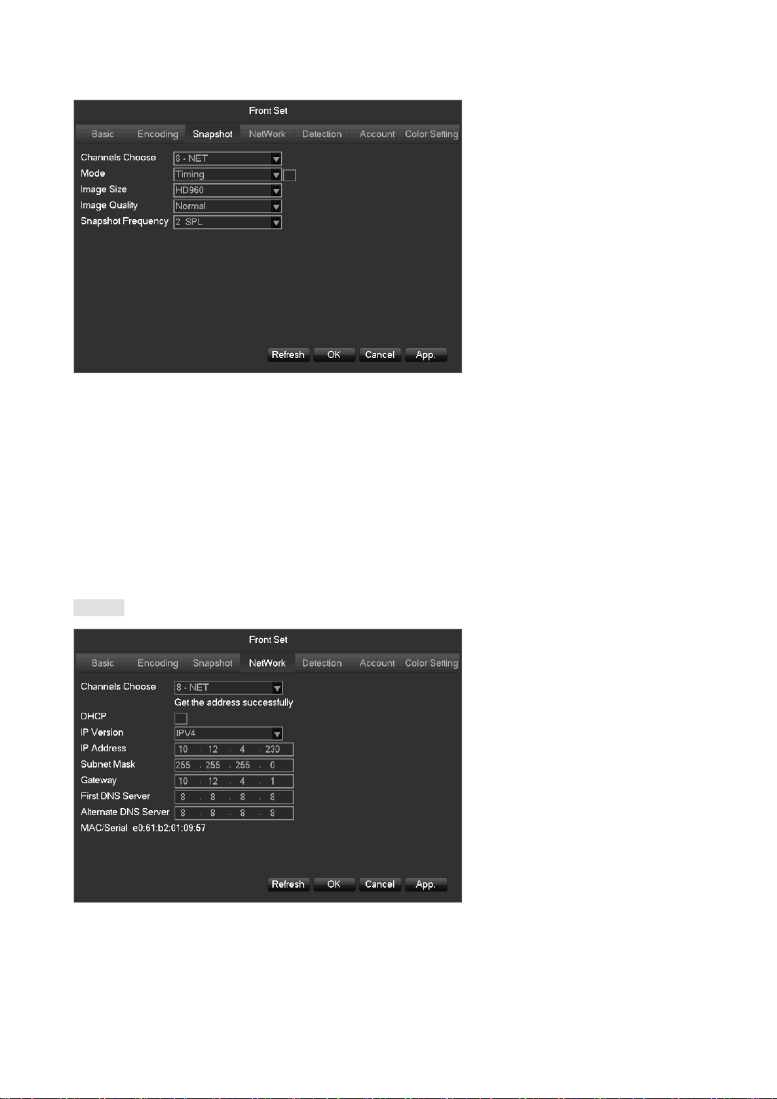
Network
[Channels Choose] Choose one channel.
[DHCP] Automatic get the IP address.
[IP Version] Choose the internet protocol version, IPV4 /IPV6.

25
[IP Address][Subnet Mask][Gateway] Set IP address, subnet mark and gateway for the device.
[First DNS Server] Set DNS server IP address.
[Alternate DNS Server] Set standby DNS server IP address.
[MAC/Serial] Show MAC address of front device.
Detection
[Channels Choose] Choose one channel.
[ Motion Enable] Enable the motion detection alarm or not.
[Dejitter] Only record one alarm event in this time, the default is 5sec.
[Set Area] Set the motion There are 396 ( ) regions can be set. detection area. 22*18
There are 6 sensitivity levels for motion detection.

26
The network protocol selected when connecting the IPC must supporting to configurate this feature. All the
settings are for front device.
[Blind Enable] Enable the blind detection alarm or not.
Account
To get the IPC’s account list.
If the current account is administrator will get the whole account list, or can’t get the other accounts
information.
Color Setting
[Channels Choose]
Select channel to modify.

27
[Config File Manage]
Support three modes, always, common, time.
[Always Use]
Support two modes, day configuration and night configuration.
[Image Params]
Get and modify the front device’s image params.
Subject to the front device model, the menu may differ the current menu in you own.-end
6.3.7 Delete Front-end Device
Click button to delete the device in [IP Channel Management] . menu
Checkmark several device batch delete devicess and click “Batch Delete” to .
6.3.8 Advanced Setting
Click the advanced setting button, will show the Advanced Setting menu.
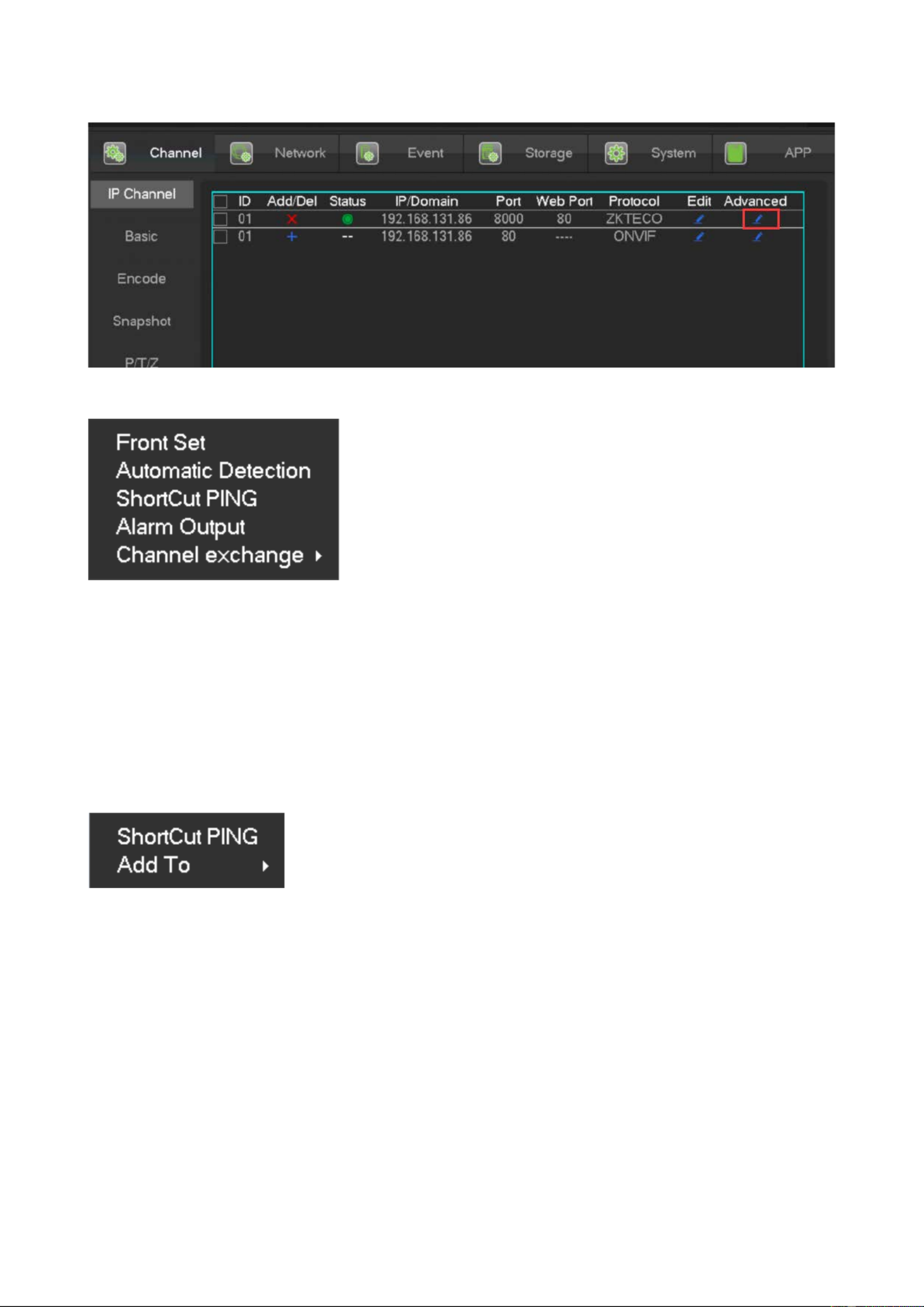
28
The front- end device has been added into IP channel:
[Front Set] Reference 6.3.6
[Automatic Detection] Check connection status of the current channel.
[ShortCut PING] Check the current channel network whether is connected.
[Alarm Output] Set the front- end device alarm output mode.
[Channel exchange] Exchange position of channels.
The front-end device has not been added into IP channel:
[ShortCut PING] Check the current equipment whether is connected.
[Add To] Add device into the special channel.
6.4 Event of Configuration The
The events ed, including traditional alarm events, equipment abnormal events, intelligent are th ose user not expect
analysis.
Configure an event event type, rules, protection plan, obey four parts: the alarm linkage.

29
6.4.1 Video Detection Configuration
The video detection motion detection video lost, video blind includes , .
[M M [ ] [ ] ain enu]- Channel - Detect Enter into the configuration interface.
Video detect
[Channel] Select a channel.
[Alarm Type] M otion detection, video lost, video blind and VQD.
[Motion Detection] Detect the motion in the picture, and send alarm according to setting.
[Video Lost] D etect the video loss and send alarm according to setting.
[Video B lind] Detect the video which was covered and send alarm according to setting.
[VQD] Analysis the video quality, if virtual , camera move or color cast, then will alarm based on the alarm plan.
[ - ] Anti Dither Will only alarm one time during this time, the default is 5sec.
[Enable] Enable the alarm or not.
[Set Area] There are totally 22*18=396 area can be set, support 4 kinds of sensitivity.
Sensitivity: Highest, higher, middle, low, lower, lowest.
[Process] Set the alarming time, linkage and the handling method.
[Linkage Config] Set the alarm linkage and the handling method.
[Preview] It will show a test on the current setting.

30
[Copy] Copy the setting to other channels.
6.4.2 Intelligent nalysisA
Cooperate with our IPC, IPC’s firmware version 112, can achieve the intelligent communication function.
A part of devices support face detection and parameter detection function he recorder analysis . T not rely on the
camera.
Mode Switch
If the intelligent analysis, into menu device s support enter [main menu]- -[ ]Channel [M Sode witch]. Choose the
channel to open the intelligent analysis function or change the intelligent function of the equipment.
The local Intelligent analysis feature depands on the mode.
Smart Configuration
Cooperation with our IPC, IPC’s firmware version 112, can achieve the intelligent communication function.

32
[Channel] Select Intelligence channel
[The minimum] The minimum area of the face detection, blue scope refer to the minimum area of the face,
the face can’t be picked if the face less than the minimum area of the face detection . According to the practical use
of scene and the expected area of the face detection to set the function.
[The biggest] The biggest area of the face detection, green scope refer to the biggest area of the face
detection, the face can’t be picked if the face bigger than the biggest area of the face detection. According to the
practical use of scene and the expected area of the face detection to set the function.
[red scope] D etection area, after set the function, the equipment only can detect the area of the face, Can
effectively reduce false positives and omission.
Perimeter Intrusion detection configuration
When the equipment open the perimeter analysis function, can enter the perimeter setting pa ge by
[ ]Channel -Alarm Type-Perimeter.
Note: if there is no channel to analysis the perimeter detection, -you can set the function by[ ]Channel Alarm
Type-Perimeter

33
[Channel] Choose the channel of the perimeter analysis.
[Rule] Click “+” add rule.
[ Set Area] Set current rule line what you choose.
[D irect] Set the fold line rules to sure the detection direction.
[R ule]
C lick [+] make the new perimeter analysis rule.
Click the color box to set the line of color rule, show in the picture:
Click the rule name can modify the name.
Click the drop - down menu to choose the other rule, then can delete the rule.
6.4.3 Alarm Configuration
Alarm Input
[Main M -[ t]enu] Even

34
[Alarm I C nput hannel No] S . elect a channel
[Enable] C . ontrol the open and close of alarm
[Type] C . hoose Normal open and Normal close
[Process] Set the alarming time, linkage and the handling method.
[S L et inkage] Show in the appendix 9.1 about set alarm linkage.
[Preview]I . t will show a test on the current setting
[Copy] Copy the setting to other channels.
Alarm Output
On the real time preview picture, right click and choose O[Alarm utput], or enter
[Main menu]-[Event]- Output] [Alarm
[Schedule] Alarm output is controlled by the device’s linkage setting.
[Manual] Alarm output is on and the status is active.
[Stop] Alarm output is off and the status is inactive.
[Status] The c status. urrent alarm output
Note:some models do not have alarm output, please refer to some relative data sheet.
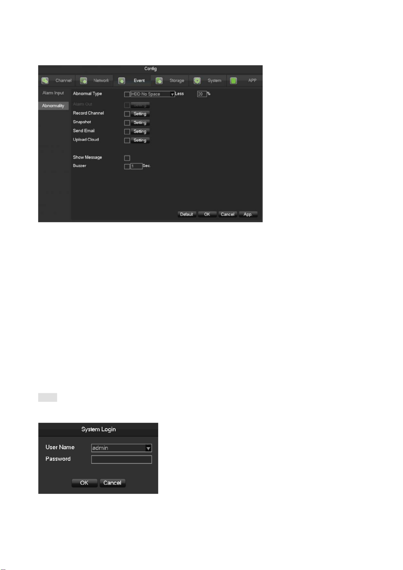
6.4.4 Abnormal Alarm
Provide multiple equipment abnormal monitoring function, and it can do the corresponding alarm linkage of
equipment abnormal events.
35
[M M [ ] [A ] ain enu]-Event -bnormality Enter the configuration interface as shown in the figure below:
[Exception type]
[No Disk] Alarm when HDD is not present or cannot be detected.
[Disk L ow Space] Alarm when hard disk capacity is lower than setting.
[Network Failure] Alarm when network is not connected.
[IP Conflict] Alarm when IP address conflict.
[Disk Error] Alarm when there is error in reading and writing hard disk.
[Alarm Output], , , , , , [linkage record] [snapshot] [Send Email] [show message] [Send to network drive] [buzzer]Show
in the appendix 9.1 about set alarm linkage.
6.5 Log in/Log out
Log in
Right click to log in menu. Enter username and password.
Default users

36
User Type Name Default Password
Administrator admin 123456
User user 123456
Hidden default
If enter error password more than 6 times, the DVR/NVR will beep, and the account will be locked. Shut
down the device then re-power it or leave the device about 5 minutes, the account will unlock automatically. To be
safety, we recommend you to modify the password before settings.
Log out
1. When over the standby time, log out automatically.
2. Enter [Main Menu]- - . [Shutdown] [Log out]
6.6 Preview
6.6.1 Live Preview
In live monitoring, there are date, time, channel name, recording status and alarm status.
Control screen switching by front panel, remote controller and mouse.
When alarm occurs, it will show message like external alarm, video loss, video blind, motion detect, network status
and IP address conflict.

37
Quick Operation
Switch single or multiple
screens
Double left click in screen to single channel and Double left click to return
Adjust channel order Drag the channel to the wanted position
Add device Click [+] in one channel to enter add menu. Please refer to 6.3.2 about more details.
6.6.2 Channel Toolbar
When mouse move on the top of windows,it will show channel toobar as follows:
Real-time playback in five minutes.
B tackup he last five minute video to U disk, backup time can be set- .
- Snapshot and backup to U disk.

38
Channel toolbar is temporarily y closed within 30 seconds.
Set the volume of sound.
Set the bothway talk.
6.6.3 Right Click Menu
Enter real time monitoring and right click menu. -
Screen Division
Choose single screen, four screens, nine screens or sixteen screens to view.
PTZ Control
Configure PTZ. Please refer to 7.2.4 and 6.3about more details for analog camera and IP camera.
After done configuration, click “PTZ Control” in corresponding channel to control PTZ.
Direction, steps, zoom, focusing, iris, preset points, cruising between points, patrols, sweeping the boundary, calling
an auxiliary switch, light switch, horizontal rotation of PTZ can be controlled.
[Direction] Support 8 directions.
[SIT] means quick location button. Make sure that the protocol supports this function. After enter the page, click a
point in screen. the point and move the point to cent PTZ will turn to er of screen. Besides, It also supports 4 to 16
times zooming when drag mouse in the quick location page.

39
The [Step] is mainly used to control directions. The figure can be set from 1 to 8. Click or to adjust
zooming, sharpness and brightness.
PTZ can control eight directions. But front panel only can control up, down, right, left.
[Present]Enter present figure in box and click “Present” button to call present function.
[Tour]Enter cruise figure in box and click “Cruise” button to call cruise between points function.
[Pattern]Enter patrol figure in box and click “Patrol” button to call patrol function.
:gray button means don’t support the function.
Configure [Present]
Present is for recording the next position, which is marked by a figure. Call the figure to enable present function.
Configure [Tour]
Tour includes several present points and is marked by a figure. When call the figure, present point will run one by
one.
Configure [Pattern]
Pattern is consisted of PTZ rotation path and is marked by a figure. Call the figure to enable patrol function.

40
Color Setting
Adjust the specified screen (single screen) image color hue, brightness, contrast, saturation, gain and white-level
parameters set two time periods according to the local environment difference between day and night for each
adjustment period set, the device will automatically switch to the best video quality.
[Period] Two periods can be set according to ambient light during the day and night, device will automatically
switch configuration time. Need to select the Enable box.
[Hue] Adjust according to image color cast
[Brightness] Visual image brightness, according to the environment, reduces or increases the brightness
of the image brightness to make the image relatively clear.
[Contrast] Adjust image of black and white in proportion, the greater ratio, the brighter image.
[Saturation] Image color purity, the greater value, the more colorful images.
[Sharpness] It reflects the image sharpness and edge sharpness of image The higher the sharpness, the contrast .
of the details on the image is higher.
[Noise Reduction] Reduce the picture noise levels, the higher the level, the less noise, but the sharpness will be
lower.
[Color Mode] Support Standard mode and Gorgeous mode.
[Image Mode] Support Real mode and Transparent mode.
41
Note: [Noise Reduction] only work for analog channel. Different mode different function
The Video Inquiry
Refer to 6.7 Search.
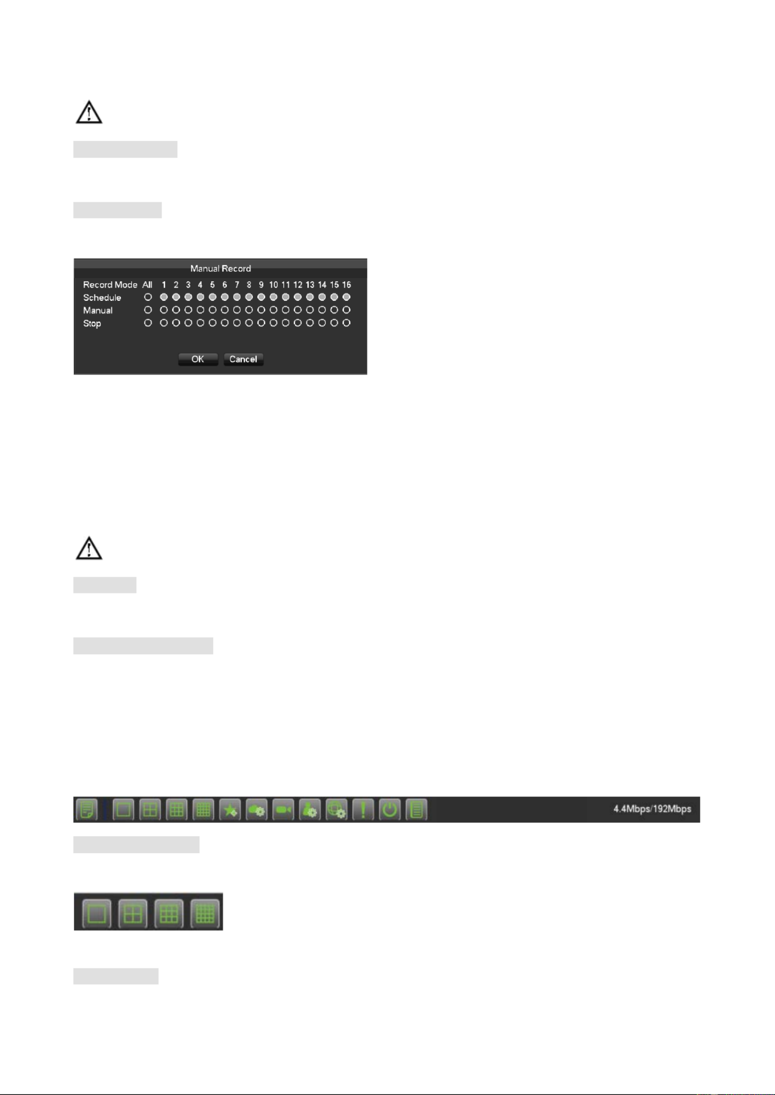
Manual Record
In real oring screen, right click and select to enter the interface.-time monit [record]
[Manual] It has the highest priority and corresponding channels will record for whole days after chosen.
[Schedule] Record according to recoding configuration.
[Stop]Stop recording.
To change a channel state of the video, at first check the video channel state is in selected or not, then use the
mouse to click, or use [
] [and
]to find the channel and use [
] [and
]to switch the video channel state.
s Note: Select all channel and enable can change the video state of all channels at the same time.
IP Channel
Refer to 6.3.3.
Reset the channel order
Click to reset the default channel order.
6.6.4 Task Bar
Enter from the main menu and provide some quick operation.
The Screen Switching
To implement screen switch function
Above single, four, nine and sixteen channel.
View Favorites

42
Support add and manage the views. Support collect channels and switch the channel sequence.
PTZ control
Brings up the PTZ control Menu
Refer to 6.4.2 PTZ control of the right- click menu.
Record Search
Click to select the Searching interface
Refer to 6.7 Search
Manual Record
Click to select manual record interface. Refer to 6.6.3 Manual record of the right- click menu.
NET Channel Management
Click to enter Net channel interface
Refer to 6.3.3
Alarm Status
Check the recent alarm status, click to show the following alarm message
Shutdown
Menu logout, device shutdown, system reboot.
Intelligent window switch
Intelligent window switch

43
When the system is face/perimeter analysis status, click to close the intelligent window in the right side of real-time
monitoring screen and click again to open it.
[Filter] Events filter: Face detection, Line Crossing detection, Instrusion detection, Object abandoned, Object
missing, Density alarm, Crossing the fence, Loitering detection, Retrograde detection.
Tag the event.
Conceal function
Color setting
Refer to 6.4.2 Color setting of the right- click menu.
Reset the channel order
Click to reset the default channel order.
Taskbar Configuration
[Taskb ] ar Mode Chose the taskbar r aesident or utomatically, Bottom and display at or TOP.

44
6.7 Search
6.7.1 Search
In real monitoring screen, right click and select to enter the searching interface.-time [search]
Record Search interface description:
Index Type Description
1 Choose the date Select the time and date to search records.
2 Select channels Choose the channels for querying.
3 Playback window Playing video.
4 Time bar channel
When you select the number of channels is more than 4, a channel
number value for the timeline display
5 List
Show the status information of channels’ video recording within one
day by green, red, yellow.
6
All Channel
Select
All select, all cancel
7 Synchronization
Achieve the playback of each channel’s record is of synchronization in
time and of consistency in operations.
8 Sub Stream Playback with sub stream recording file.
9 Playback control
Full screen, Loop,
Stop/Play、Pause、Fast、Slow、Back、 、Previous Frame Next Frame.
10 Video Edit Tool To realize snap, tag, video cut, etc. functions.

45
11 Event list Show all events and time
12 Timeline display Green, red and yellow colors show the video recording in the one day
13 Search Type
128 video records are shown in the list.
Type: R— —normal record, A alarm record, M—
motion detection
record.
List:
Key D Type escription
1 Time Choose video query time
2 Channel Select the desired query video channel
3 File Query channel video display a list of files
4 File information Display start time for a single video file, the end time, and video file size.
5 Backup
In the file list box, select the user needs to back up files in the list box playing
" " to check, and then click the button (backup) or (uploaded to the
cloud disk), the backup operation menu appears, click the Start button, users
can also do not want to cancel the backup files in the backup operation
menu before you want to cancel the file list box cancel "".
46
6 Back Exit File List
Playback Control:
Key Description Remark
Video playback:
Fast-forward Key
Under playback mode, pressing this key, you
can get a variety of fast cycle switching
speeds; fast-forward button can be
used as
slow-release button reverse switch key.
Actual play rate based on
version
Video playback :
Slow key
Under playback mode, pressing this key,
switch cyclically support a variety of
slow-release rate, slow release button can be
used as fast- forward
button reverse switch
key.
Play/pause►/ Play/pause switch when slow- play
Backward:
Backward key
Single left click backward key
To play backwards and
single click again to stop
back run under common
playback Rewind or
single-
frame playback,
press the play button ►/
###
to enter the normal
playback .
Manual single frame
playback
single frame playback by clicking ###│and
│###when common playback pause
Audio Adjust the audio
Full screen Full screen
When the loop is turned on, the day after the
end of the video playback, video playback file
start over again
Display the current status: normal playback,
reverse playback, fast playback level, etc.
Just display the status,
can’ t set.

47
1. The player playback control bar shows file playback speed, channel, time, playback progress and other
information.
2. Playback speed and rewind function are related to DVR version, and please prompt on the player panel shall
prevail.
Video edit button:
Key Description Remark
Snapshot:
When Playback, left-click on the icon, the snapshot of
focus on back up to the U diskwindow will
Insert U disk, enter Search ,
supports a maximum
resolution of 1080P
Tag:
Left- click the icon, you can add tags to focus channel
set the tag name letters,
numbers, special characters,
the total length of no more
than 31 characters. The tags
can be used to add labels to
retrieve.
Cut:
Left click , , :start to cut record Starting time
click focus window,icon turn to ;
left click
again complete cutting,End time click focus :
window。After finish cutting,click to back up record
,
or right click to exit cut feature。
If the focus of the shearing
process channel change, places
the focus of the channel when
the end of the shear cut as a
video channel.
Shearing process can playback
control.
When the cut end time is
earlier than the start time cut,
cut start time automatically
reversed.

48
6.7.2 Event Search
Select the channel, start time, event type, click on the retrieval button to pop up a list of events as shown below
Event eventList 10 Showing s, to display the event channel number, event type, time, time of occurrence.
Index Type Description
1 Play Timeline Display the progress bar of the current event
2 Search Search recoding
3 Event Type Select the type of event
4 Channel selection Select the channel
5 Select al channel Select al channel
49
List of events - can flip through page keys. Double click the event list for playback directly.
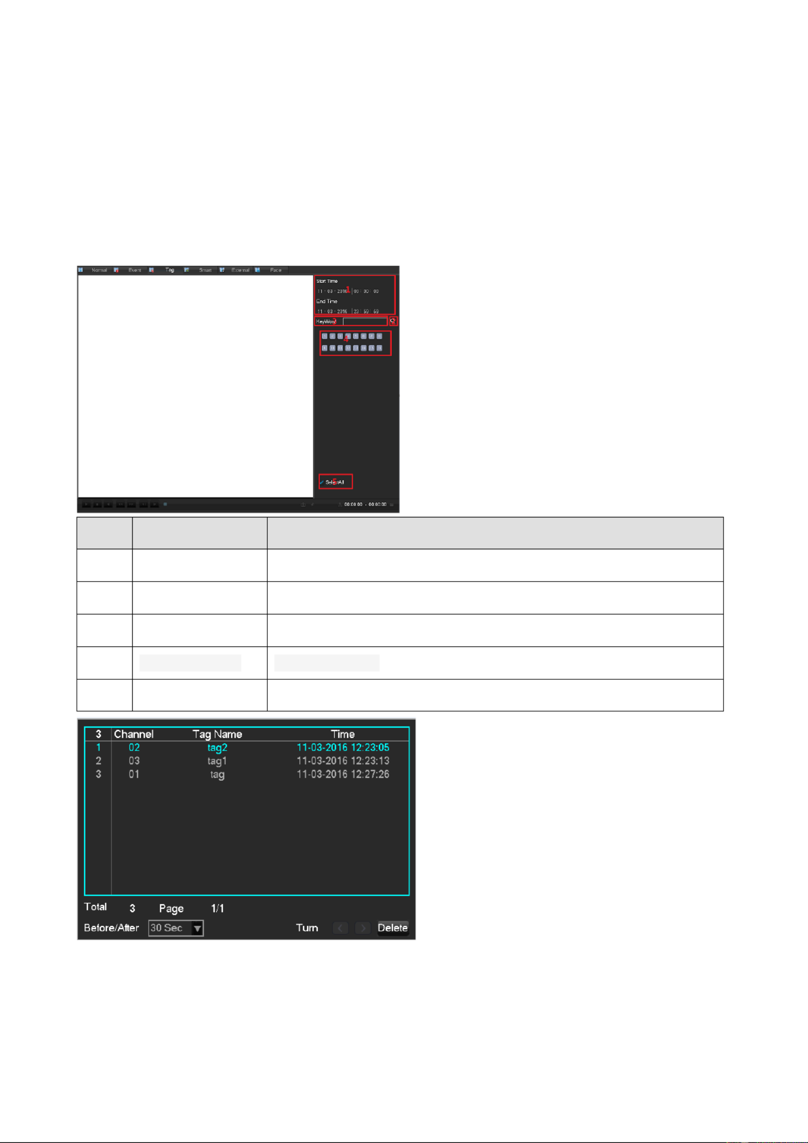
The default before and after the can be configured to time of 30 seconds event to play video files, around 30
seconds, 1 minute, 5 minutes, 10 minutes
6.7.3 Tag Search
Index Type Description
1 Play Timeline Display the progress bar of the current event
2 Search Search recoding
3 Event Type Select the type of event
4 Channel selection Select the channel
5 Select al channel Select al channel

50
6.7.4 Smart Search
Intelligent playback that video playback time, according to the input retrieval conditions, video analysis, quickly
locating the qualified video, and playback.
Currently our DVR, TVR device supports retrieval based on intelligent motion detection playback area.
Enter the smart playback interface, the interface as shown in FIG.
Intelligent playback using the following process
1. Position 1, select the desired search date.
2. Position 2, select the desired search channel (radio).
3. L - eft click on the third position to start playback.
4. L -eft click on the icon position 4, select dynamic inspection area.
5. Full-screen setting area is completed, the right mouse button to exit the configuration. Complete search,
video recording shall be the date the presence of all the moving subject information of the channel region is
configured to display on the timeline.

51
6.7.5 External Search
Index Type Description
1 File Path Playback of each channel’s of synchronization.
2 Folder Contents Select channels desired to query records.
3
File Control
[ -Device Detect] Left click the device detects the detection
insert U disk
[ ] Delete Left click, delete the file
[Back] Click
the left mouse button to return to the
previous folder

52
6.7.6 Face search
Index Type Description
1 Play windows Play the video.
2 Play Timeline Display the progress bar of the current event
3 Playback control
Stopping / playing, pausing, fast playing, slow playing and
the previous/next frame on a suspended state.
4 Calendar Select the date to search records.
5 Face list Show the all face images of the channel in the query time.
6 Channel number Select the channel number.
7 Search Click to search out record files.
8 Time Search
Search the records based on the starting time and end
time.
9 Face Statistic
Display the total number of face images and pages of the
channel in the query time .
10 Page number
Display the current page and the total number of pages.
Page up and page down.

53
11 Export Export all the face images of the current page..
12 T Process he process of backup
6.8 Record Backup
Interface D escription
Connect an External USB device with the USB port to backup in the file [Record Backup] menu.
[Detect] Identify external USB device and display the device information.
[Backup] Tick the external device and click to enter the backup menu . [Backup]
[Cancel] D elete all data in USB backup device
Backup Operations
Connect an External USB device with the USB port, click [Detect] to Identify external USB device, click

54
[Backup] to enter the backup menu, - select the record start stop time and click to add files in list, click
[Start] to backup and display time remaining.
USB backup carry player automatically. This operation probably will cause permanent data loss.

55
7 L l oca Configuration
7.1 The Introduction he Main Menuo Tf
The main menu is shown as the following interface:
Operation
[Search] B ased on time, time, label, query and playback video files.
[Backup] B ackup device detection and video data.
[Shut Down] User logs off the device, the device shut down and reboot the system.
INFO
[System] D isplays the system status, hard drive status, version information.
[Event] displays alarm information.
[Net] Stream state, the online user information.
[Log] System log information.
Config
[Channel] Add / Remove the camera, the camera parameters, the basic parameters of the channel
configuration, channel mode switch, channel events and joint management parameters.
[Network] Basic network configuration parameters settings, manage network interfaces, configure advanced
network services.
[Event] External alarm events and abnormal events of the configuration parameters of the device and joint

56
management.
[ ]Storage Hard disk storage configuration management, video parameter settings, set the record schedule.
[System] Configuration System parameters time, date, language configuration, management and video
output parameters polling settings.
[Application Center]E-mail, P2P, cloud storage, mobile phones and other common functions push settings.
7.2 INFO
7.2.1 System
It displays the current total capacity of DVR hard disk, the remaining capacity and working conditions. As shown
below:
HDD Manage
Record Time
Show starting and ending time of the computer's hard disk recording. As shown below

57
Version
The display device serial number, system hardware features, software version and release date information. As
shown below
7.2.2 Event
Displays the current alarm status

58
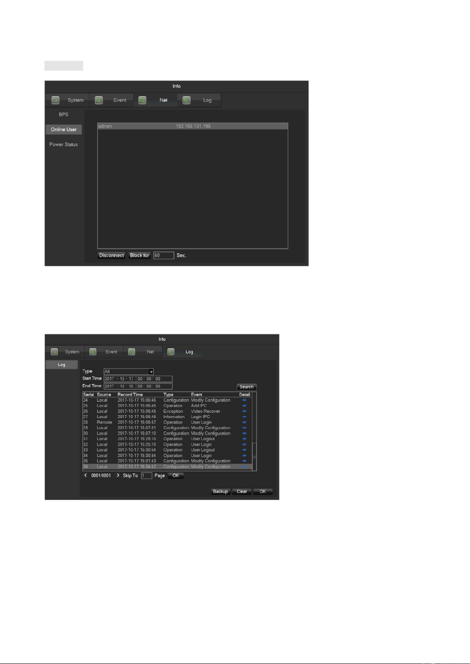
7.2.3 Net Information
The equipment with input function use network channel management page for add or delete the equipment and
set the front- end configuration.
BPS
count the bitrate of each channel, the value is an estimated value.
59
O nline User
View the current online user status, disconnect and shielding.
7.2.4 LOG
Log information can be divided into system operation, configuration operation, data management, alarm event,
recording operation, user management, log clear, file operations.
Select the type and time of the query, press the Find button, the system displays the log as a list, and click the
Backup button will log export backup to your computer.
Click the Clear button, the system will remove all types of log files.

60
7.3 CONFIG
7.3.1 Channel Setting
IP Channel
The operations to add / delete IPCs into NVR refer to 6.3.3 IP Channel Management.
Base
[Channel] Choose the channel no. which needs setting.
[Channel Name] S . et the channel name if in need
[Channel Display] Set the channel name’s display place on the picture.
[Time Display] Set the time’s display place on the picture.
[Time Synchronization] Synchronize the time with net channel and device.
[Video Cover] Set some special area which needs special protection while preview and recording.
Encode

62
[Channel] Select a channel.
[Mode] Trigger: Crawl images when alarm. Click to enable the function.
[Image size] Choose different resolution for snapshot.
[Image Quality] There are 6 levels of quality.
[Snapshot frequency]set highest capture rate for single channel, 1/2/3/4/5/6/7/8 s/pc.
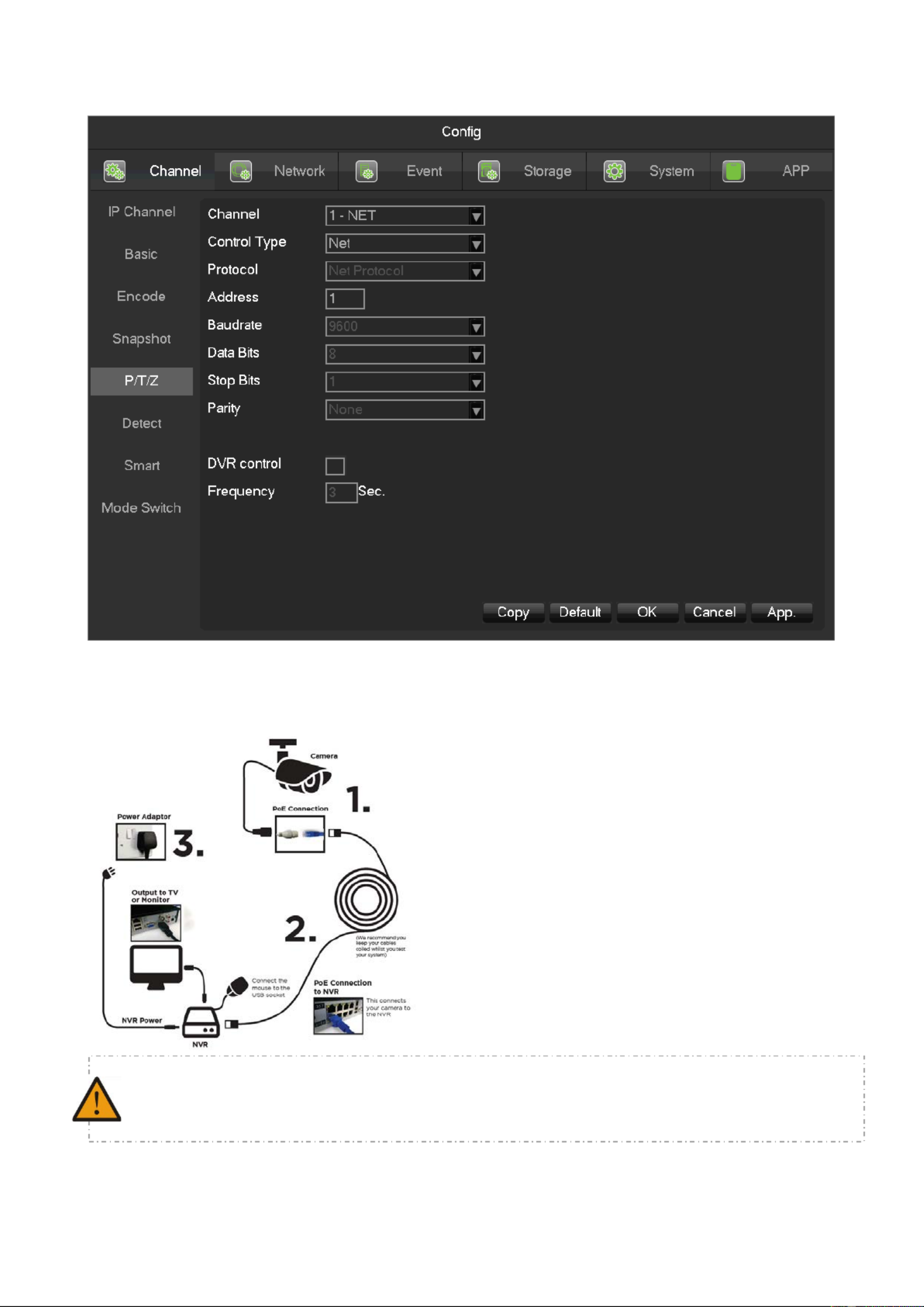
P/T/Z Control
[Channel] Select the PTZ channel to set.
[Control Type] Chose coaxitron or RS485, based on the channel type.
[Protocol] Select the PTZ protocol (e.g. PELCOD).
[Address] The PTZ’s address.
[Baudrate] The PTZ’s baudrate, can find it in the PTZ OSD, the default is 9600.
[Data Bits] Default is 8.
[Stop Bits] Default is 1.
[Parity] Default is none.
[DVR Control] Enable it can virtual the PTZ features.
[Frequency] Default is 3sec. The value range is 1~30secs.
Detect
Video detection includes motion detection, video lost, video blind. The details refer to 6.4.1.

63
Smart
The details refer to 6.4.2.
Mode Switch
The details refer to 6.3.1 and 6.4.2.
7.3.2 Network
This menu section allows you to configure the network settings of the NVR. It is recommended that an experienced
network technician should only be able to configure settings in this menu section.
Basic
[Network Card Type] LAN1: Default IP is 192.168.1.88;
LAN2: Default IP is 192.168.2.88
LAN2 is used to POE the IP camera. If the IP Camera is connected to the POE, the IP address of IP
CAMERA and NVR must be in the same network segment.
[DHCP] Enable the NVR to obtain an IP address automatically. If it is enabled, the NVR will reboot and
search for a DHCP server, and then assign a dynamic IP address. The dynamic IP address will be displayed in the
menu. Enter a static IP address if there is no DHCP service available. If you are using the advanced feature PPPOE,
then the IP/mask/gateway and DHCP are unable to be changed.
[ ]IP Address (Use ) or input numbers to modify IP, then set [ ]subnet mask and [ ]default gateway for

64
this IP.
[AUTO DNS] Get the DNS from the DNS server automatically.
[First DNS Server] DNS server IP address.
[Alternate DNS Server] DNS alternate IP address.
[Physical Address] Physical address of current net port.
[MTU] Default is 1500, range is 128-1500.
Advanced
[TCP] Default: 8000, variable.
[HTTP] Default: 80.
[UDP] Default: 8001.
[RTP/RTSP PORT] Default: 554.
[Multicast] Tick ‘Multicast’ and set a group in ‘ ’Set, IP should be limited as follow picture, port no limit.
Application

66
[NTP]Select Enable switch to turn on the NTP protocol support, can be with SNTP communication server to
realize automatic calibration function.
Host IP: Enter the IP of NTP service NTP.
Port: Supports TCP transport only, port is limited only 123.
Update cycle: interval time is 1 minute or more, the maximum update period is set to 65,535 minutes.
Time Zone: London GMT+0, Berlin GMT +1, Cairo GMT +2, Moscow GMT +3,
New Delhi GMT +5, Bangkok GMT +7, Hong Kong & Beijing GMT +8, Tokyo GMT +9, Sydney GMT +10, Hawaii
GMT-10, Alaska GMT-9, Pacific Time GMT- 8,
US Mountain Time GMT-7, US Central Time GMT-6, US East Time GMT-5, Atlantic Time GMT-4, Brazil GMT- – 3, Atlantic
Central GMT- 2.
[FTP] Select the Enable box to make the protocol enable to enter the FTP settings menu,.

67
Two kinds of FTP upload file types are video files and pictures, set up an FTP server address, port, remote directories
and so on. When remote directory is empty, the system will automatically create a different folder by IP, time,
channel.
User name & password: access the FTP username and password.
Set upload file size, you need to upload the file channel, time, type, etc.
Set upload length which upload to FTP server file length, if less than the set value, the entire video file upload; If
more than the set value, upload take part from the beginning and set the value of consistency, the file later
omitted; setting a value of 0, then upload the entire video file.
Different channels can be set two different time periods, three types of video recording.
[IP Permissions] For permission to access the DVR IP rights management. When choosing the white list, the
list indicates that only the IP to connect this DVR. Up to 64 IPs. If the selected item is not ticked, no restrictions on
accessing to the device's IP.

68
[Alarm Center] Alarm interface for customers to reserve the use of self- development.
[Register] Device connects to the platform automatically.
[Transcapacity]

69
[Max Connection] The number of connections: 0- 20, if you set o means the network does not allow
users to connect, the maximum number of connections is 20.
[Network Connection NUM] The number of connections defaults to three times the number of
channels. Real-time video over the network for browsing, the number of connections depending on network
bandwidth, the number greater, the larger the network load, will impact of video playback fluency.
[Network Download NUM] The number of connections to download recommendations: 0 8, this need -
to tick to start this function.
[Network transmission QOS] smooth network transmission quality priority or image quality priority or
adaptive, depending on the setting, the network adjusts the stream automatically.
IPC UPNP
To allocate virtual IP address to our IPC. This is the IP segment.
Security Center

70
RTSP service, remote debug, TCP auth enhancement switch. Only enable them can work.
7.3.3 Ev ent
Alarm Input
The details refer to 6.4.3.
Alarm Output
The details refer to 6.4.3.
Abnormality
The details refer to 6.4.4.
7.3.4 Storage
HDD Manage
Show the HDD space and status.
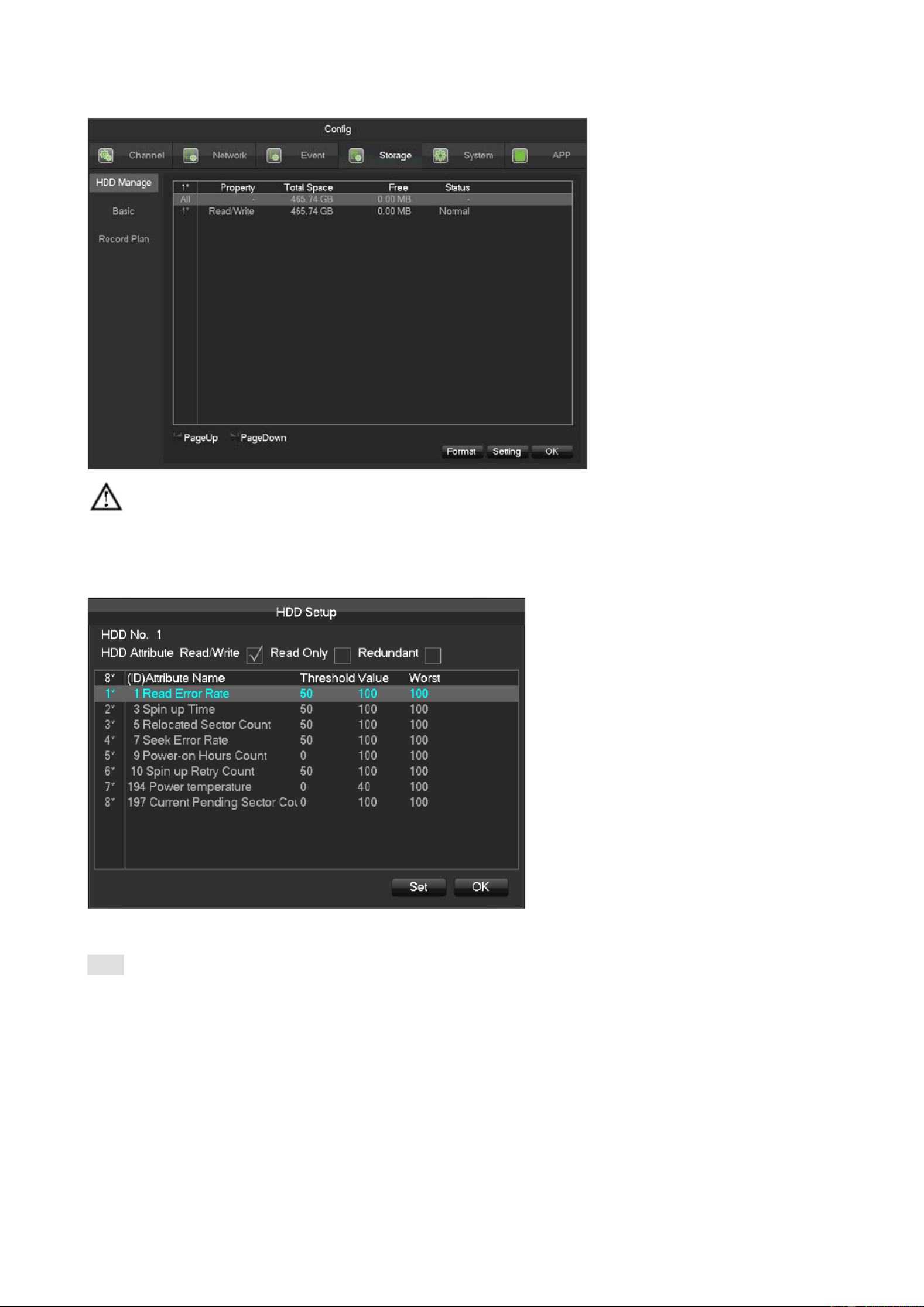
71
Note: Hard disk format operation results in the loss of video data.
[Set] Set HDD as read-write, read only or redundancy mode. Video data can be protected from covering
under read only mode. It supports HDD S.M.A.R.T smart detection at the same time.
Basic

72
[ M ] Record ode Support three modes, r ecord automatically, manually or not record.
[Record Overlay] The range is 0~31.
[Video Package Time] The figure is between 5 to 120 minutes.
[HDD Full] Overwrite or stop recording.
[Sub Record] -Sub stream recording switch. Enable it, then will recording with sub- . stream and main stream
[Channel] Select a channel.
[Video Redundancy] Open or close the redundant recording.
[Prerecorded]The figure is between 0 to 30 seconds.
Recording plan

73
[Channel] Select a channel. Green shows normal recording, Yellow shows motion detection, and Red shows
Alarm. Users can set or change setting according to date.
[Copy] Copy the setting to other channels.
Click [Set] and enter into plan editing picture
[Period] Set the recording period, there will be 6 period to choose.
[Regular] R egular recording.
[MD] Motion detection recording.
[Alarm] A . larm recording
7.3.5 System Configuration
Basic setting
Get into the menu under [Ba ] sic [Configuration]
[System Time] . set the HD record system time
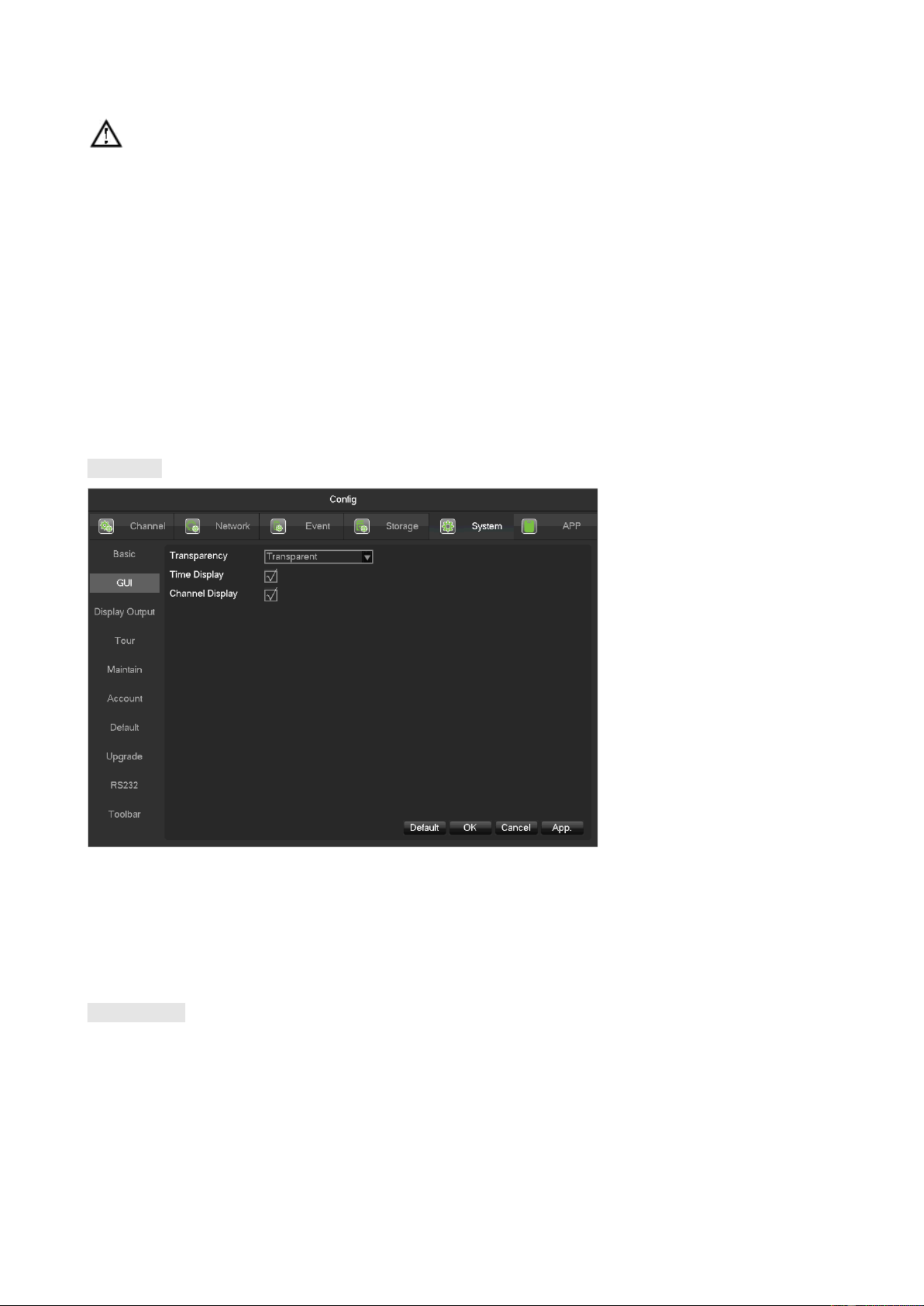
74
Note:please click the”save” button to save the time after setting.
[Daylight Saving Time (DST)] Enable the function and click “Set” to enter the local DST starting and
ending time setting.
[Date Format]Modify the date display format.
[Date Separator]Select the separator for date.
[Time Format] 24 hour . or 12 hour display mode
[Time Zone] Select the time zone.
[Language] Select language (different models have different language choice).
GUI Display
[Menu Transparency] Adjust menu transparency , four degrees
[Time Display] Enable switch for time displayed in live view
[C Dhannel isplay] Enable switch for channel name displayed in live view
Display Output

75
[Display] CVBS/HDMI&VGA
Under CVBS mode, user can adjust the monitor or TV hue, brightness, contrast and saturation. You can also adjust
the right TV output area when the displayed image is not full or beyond the scope of the monitor. Under
HDMI&VGA mode, user can only adjust the monitor hue, brightness, contrast and saturation.
[Resolution] Select the VGA output resolution and refresh rate.
[VGA Display Enable] Enable it, then VGA and HDMI will display different image.
[VGA Display Least Time] Tour interval time, the value range is 5-120sec. The alarm information linkage
to VGA auxiliary output need to enable single-screen or four-screen display.
[VGA Display Enable] feature only for special models, the device you have may not support, please prevail in
kind.
Tour
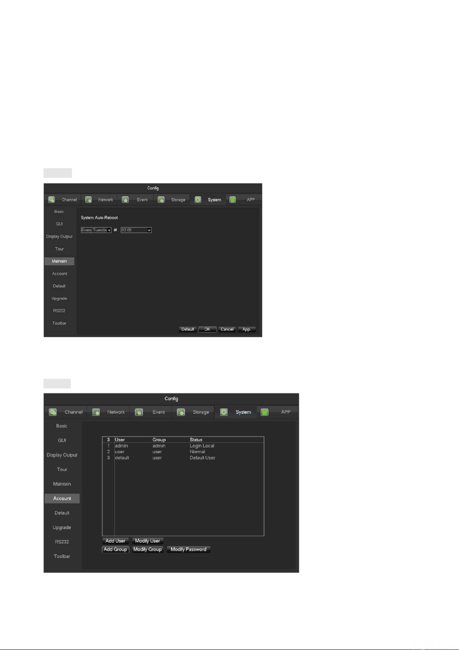
76
[Enable Tour] . Enable switch
[Interval] Tour interval time is 5- . 120s
[View] It includes single screen, four , nine , sixteen- - -screen.
[Motion Tour] Set the motion detection tour mode.
[Alarm Tour] . Set the alarm tour mode
Maintain
[Auto maintain] Set the desired the project of automatic maintenance.
Account
[Add User] Increase users within the group and settings user access control.

77
[Modify User] Modify the user and settings user access control.
[Add Group] Add group and settings group access control. Enter into the menu interface of Increase the
group, determine the group name, select 83 access control, left click mouse button to confirm, save the new user
group.
[Modify Group] To modify the group attribute which already exists.
[Modify Password] To modify password.
Select the user enter old password then enter new password and confirm,
Click [confirm] button to make sure modify password.
The password can be set 1 6. Beginning and ending spaces is invalid password, you can have a space in -
the middle.
Users which has User Account Control permission can change their own passwords, can also modify
other users' passwords.
The following user names and user group names, etc., character and length consisting up to six bytes,
the invalid string is trailing spaces. Legal characters: letters, numbers, underscores, minus sign, point, other
characters are not allowed to use.
the number of users and groups is not limited,User Group increased or delete according to user-defined::The
factory settings are user admin two groups. Users can set their own related group, the group of users can be \
freely re- assign permissions at the group permissions.
user management using two methods of user and group, Group name and the user name cannot be ,
repeated,,each user must belong to a group, a user can belong to only one group.
There are three users: admin, user, and hidden default initialization. The factory password for first two are
123456. Admin default user permissions are high at the factory, and the factory default user as a low privileged
user, only for monitoring, playback.
Hidden default: This user system for internal use and cannot be deleted. When local is in "no user is logged"
state, the system will automatically log in with this account. Users can modify this account permission to do
what free login can do.
Enter to the menu interface of increase user, Enter your user name and password, select belongs to which
group, and select whether to reuse this user. Reuse means that the account can be used simultaneously,
multiple clients can use the account.

78
Once the group belongs selected, the user's permissions only a subset of the group, not ultra vires the properties of
the group.
Default
System back to the default configuration factory state (specific items recovered optional)
Menu color, language, time and date format, video format, IP address, user accountsand so on will not be
restored.
Upgrade
System software can be upgraded: Insert a USB storage device, click Upgrade.
System upgrade may cause the DVR can not start properly, please Operation under the guidance of the
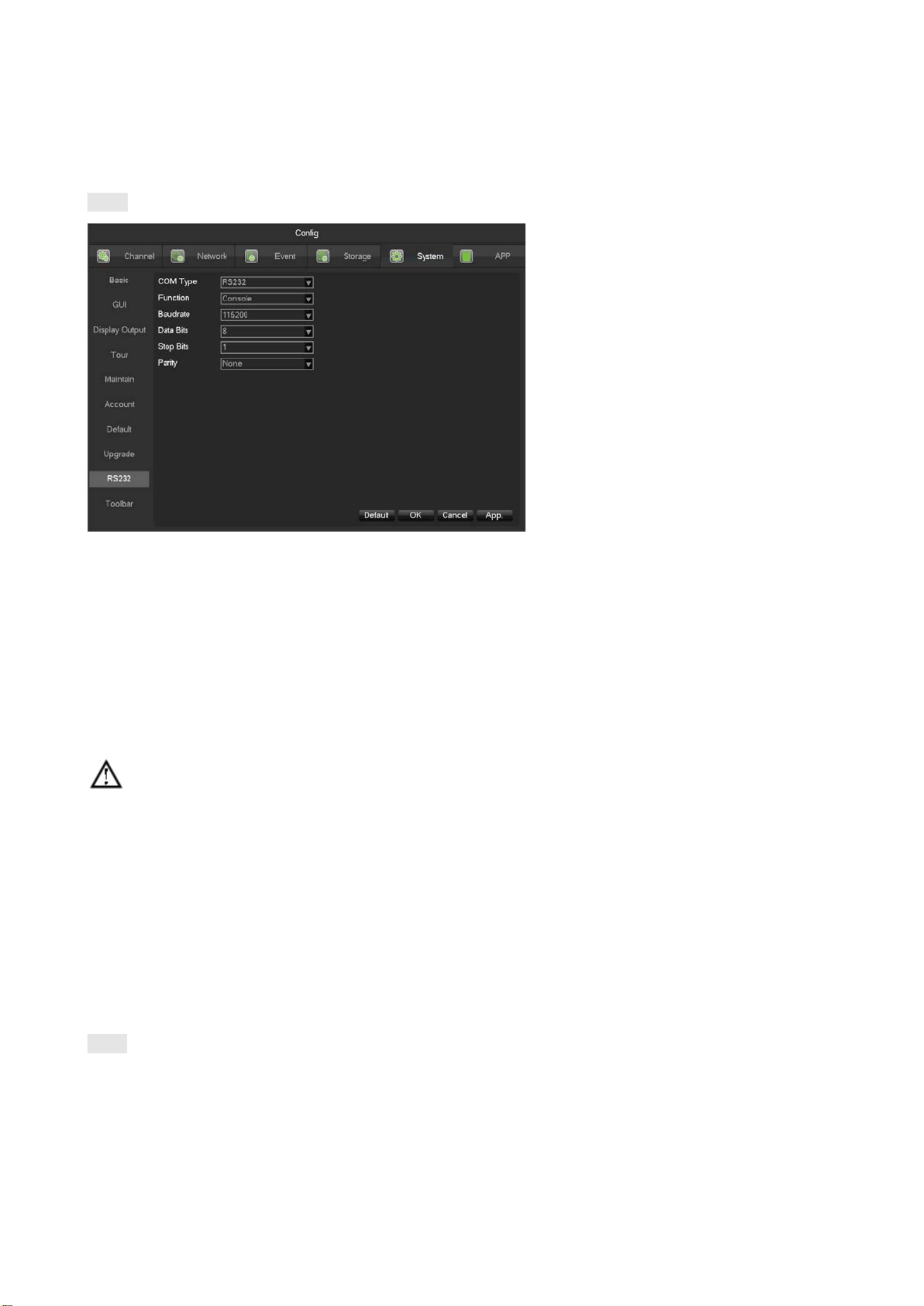
79
company's technical staff.
RS232
[Function] Select the appropriate serial protocol.
[Regular] U . sed to update firmware and adjust
[Keyboard] U . sed specialized keyboard to control the device by serial port
[Transparent serial port] U . sed to transmit serial port data transparently
[Net keyboard] U . se specialized keyboard to control the device through network
[PTZ] C . onnect with matrix
Note:some models do not have RS-232 serial port, please refer to some relative data sheet.
[Baudrate] Select the relative length of baud rate.
[Data Bits] D . efault: 8
[Stop Bits] D . efault: 1
[Parity] D . efault: None
7.3.6 APP Center
DDNS
Dynamic DNS is a kind of system which point internet domain name to variable IP. According to the rule of internet
domain name, domain name must associate with the fixed IP address. Dynamic DNS provide a fixed Name server
for the dynamic domain, and then guide the domain search to the IP address of dynamic user through Name server,

81
Name Configuration
DDNS type IP DDNS -NO
Host IP - dynupdate.no ip.com
port 80
Domain name
xxx.xxx.org xxx( :
domain name
created)
User name xxx(user name registered)
password xxxxxx (password registered)
3、
、
、
、、Dyndns DDNS
Register new account at www.dyndns.com.
Embedded DVR/NVR Setting:
Open [Main Menu] [APP Centre]- - - [DDNS], choose NO IP DDNS.
Refer to the following configuration:
Name Configuration
DDNS type Dyndns DDNS
Host IP Members.dyndns.org
port 80
Domain name xxx.xxx.com( :xxx domain name created
)
User name xxx(user name registered)
password xxxxxx (password registered)
Email

83
[Local Port] S . et local port
[P2P Server URL] P2P server URL.
[State] C . urrent connection state
Cloud Storage
Refer to 9.1.10 . Send Cloud NetDisk
Push

84
Refer to 9.1.9 Push Server.

85
8 WEB Access
8.1 WEB Operation
8.1.1 Network Connection
Check ing whether the DVR is on the network by check B-Lamp on front panel, light indicates connection,
otherw ise connection error.
Set IP, subnet mask and gateway for computer and DVR. Please assign the same segment IP address without router,
need to set the appropriate subnet mask and gateway with router.
The detail of DVR network configuration please see [Configuration]-[Network Setting].
Ensure the IP is correct and check whether the DVR is on the network by using the Windows command “ping”.
8.1.2 The control installation and the user login logout
Users can remote access to DVR by Internet Explorer, assuming you have a correct network configuration.
The following interface will pop up when you access the IP address in Internet Explorer.
The following interface will pop up when you log in.

86
Will be displayed in Compatibility View option is checked on all websites.
8.1.3 The Interface o f Web Operations
WEB Interface Description
After log in the web, the preview interface will pop as following:

90
Border scan
Operation: select the camera line scan of the left/right margin by direction button, and click the Settings button in
the left /right margin position to determine the left border.
Preset
Operation: modify preset position by direction button and inputting a preset number, then click “Add” to save.
Tour
Operation: select “Tour”; Point between the first cruise line cruise input box value. And input numbers in “Path” and
“preset”. Click to add one preset in the cruise path, and repeat to add additional presets. Click [Add Preset] [Clear
Preset]to delete a preset, repeat to delete more.
Pattern
Operation: Click “Pattern” in order to record an automated pattern. Then, go back to the PTZ controls in order to
modify the zoom, focus and IRIS, etc. Stop recording in “Pattern” setting to save the pattern.
AUX
On/off one of AUX.
Wiper
On/off wiper under protocol.
8.1.4 Configuration
Access DVR local configuration menu by click “System Config.”, the further details please refer.
[Local operation guide]
Produktspezifikationen
| Marke: | ZKTeco |
| Kategorie: | Sicherheitskamera |
| Modell: | Z3104/08 XER-C |
Brauchst du Hilfe?
Wenn Sie Hilfe mit ZKTeco Z3104/08 XER-C benötigen, stellen Sie unten eine Frage und andere Benutzer werden Ihnen antworten
Bedienungsanleitung Sicherheitskamera ZKTeco

11 August 2024
4 Mai 2024
15 April 2024
14 März 2024
11 März 2024
10 März 2024
11 Februar 2024
9 Februar 2024
18 Januar 2024
11 Januar 2024
Bedienungsanleitung Sicherheitskamera
- Sicherheitskamera Samsung
- Sicherheitskamera Anker
- Sicherheitskamera Approx
- Sicherheitskamera Sanyo
- Sicherheitskamera Exibel
- Sicherheitskamera Gembird
- Sicherheitskamera Hama
- Sicherheitskamera LogiLink
- Sicherheitskamera Logitech
- Sicherheitskamera Manhattan
- Sicherheitskamera Nedis
- Sicherheitskamera Sony
- Sicherheitskamera Panasonic
- Sicherheitskamera Clas Ohlson
- Sicherheitskamera Profile
- Sicherheitskamera LG
- Sicherheitskamera Bosch
- Sicherheitskamera Canon
- Sicherheitskamera TechniSat
- Sicherheitskamera Allnet
- Sicherheitskamera Eminent
- Sicherheitskamera Linksys
- Sicherheitskamera Maginon
- Sicherheitskamera Netgear
- Sicherheitskamera Schwaiger
- Sicherheitskamera Technaxx
- Sicherheitskamera Alecto
- Sicherheitskamera Denver
- Sicherheitskamera EMOS
- Sicherheitskamera Gira
- Sicherheitskamera König
- Sicherheitskamera Thomson
- Sicherheitskamera Blaupunkt
- Sicherheitskamera Braun
- Sicherheitskamera Grundig
- Sicherheitskamera Trebs
- Sicherheitskamera Pyle
- Sicherheitskamera Mitsubishi
- Sicherheitskamera Fortinet
- Sicherheitskamera Caliber
- Sicherheitskamera I-Onik
- Sicherheitskamera Jay-Tech
- Sicherheitskamera JVC
- Sicherheitskamera Motorola
- Sicherheitskamera Xiaomi
- Sicherheitskamera Abus
- Sicherheitskamera Avidsen
- Sicherheitskamera Elro
- Sicherheitskamera EZVIZ
- Sicherheitskamera Imou
- Sicherheitskamera INSTAR
- Sicherheitskamera Megasat
- Sicherheitskamera Olympia
- Sicherheitskamera Smartwares
- Sicherheitskamera Switel
- Sicherheitskamera Yale
- Sicherheitskamera Ferguson
- Sicherheitskamera Strong
- Sicherheitskamera Toshiba
- Sicherheitskamera E-Bench
- Sicherheitskamera Withings
- Sicherheitskamera Lindy
- Sicherheitskamera Waeco
- Sicherheitskamera Burg Wächter
- Sicherheitskamera Marmitek
- Sicherheitskamera Marshall
- Sicherheitskamera Honeywell
- Sicherheitskamera B/R/K
- Sicherheitskamera Marshall Electronics
- Sicherheitskamera TRENDnet
- Sicherheitskamera MINOX
- Sicherheitskamera Ricoh
- Sicherheitskamera Western Digital
- Sicherheitskamera RADEMACHER
- Sicherheitskamera First Alert
- Sicherheitskamera AVerMedia
- Sicherheitskamera Zebra
- Sicherheitskamera TP-Link
- Sicherheitskamera Humax
- Sicherheitskamera Flamingo
- Sicherheitskamera Kerbl
- Sicherheitskamera Vtech
- Sicherheitskamera Kodak
- Sicherheitskamera Broan
- Sicherheitskamera IGet
- Sicherheitskamera Adj
- Sicherheitskamera Netatmo
- Sicherheitskamera Xavax
- Sicherheitskamera InFocus
- Sicherheitskamera Overmax
- Sicherheitskamera Monacor
- Sicherheitskamera JUNG
- Sicherheitskamera Ednet
- Sicherheitskamera AG Neovo
- Sicherheitskamera Nest
- Sicherheitskamera Edimax
- Sicherheitskamera Aritech
- Sicherheitskamera Uniden
- Sicherheitskamera M-e
- Sicherheitskamera Siedle
- Sicherheitskamera Elmo
- Sicherheitskamera Conceptronic
- Sicherheitskamera D-Link
- Sicherheitskamera Eufy
- Sicherheitskamera Stabo
- Sicherheitskamera Friedland
- Sicherheitskamera EVOLVEO
- Sicherheitskamera ION
- Sicherheitskamera SPC
- Sicherheitskamera Ring
- Sicherheitskamera Digitus
- Sicherheitskamera SereneLife
- Sicherheitskamera Swann
- Sicherheitskamera Vitek
- Sicherheitskamera DataVideo
- Sicherheitskamera LevelOne
- Sicherheitskamera APC
- Sicherheitskamera Cisco
- Sicherheitskamera Grandstream
- Sicherheitskamera EVE
- Sicherheitskamera EasyMaxx
- Sicherheitskamera Tenda
- Sicherheitskamera Boss
- Sicherheitskamera Swisstone
- Sicherheitskamera Foscam
- Sicherheitskamera Ubiquiti Networks
- Sicherheitskamera Extech
- Sicherheitskamera Kramer
- Sicherheitskamera Intellinet
- Sicherheitskamera Reolink
- Sicherheitskamera Hikvision
- Sicherheitskamera FLIR
- Sicherheitskamera Arlo
- Sicherheitskamera Nexxt
- Sicherheitskamera Planet
- Sicherheitskamera EnGenius
- Sicherheitskamera Lorex
- Sicherheitskamera Google
- Sicherheitskamera Comtrend
- Sicherheitskamera Somfy
- Sicherheitskamera Aldi
- Sicherheitskamera Dedicated Micros
- Sicherheitskamera EverFocus
- Sicherheitskamera Ganz
- Sicherheitskamera GeoVision
- Sicherheitskamera Indexa
- Sicherheitskamera Raymarine
- Sicherheitskamera Revo
- Sicherheitskamera SecurityMan
- Sicherheitskamera Sitecom
- Sicherheitskamera Steren
- Sicherheitskamera Vivotek
- Sicherheitskamera Wanscam
- Sicherheitskamera Y-cam
- Sicherheitskamera ACTi
- Sicherheitskamera Epcom
- Sicherheitskamera Moxa
- Sicherheitskamera Sonoff
- Sicherheitskamera AirLive
- Sicherheitskamera Mobotix
- Sicherheitskamera Hollyland
- Sicherheitskamera Avanti
- Sicherheitskamera Dahua Technology
- Sicherheitskamera Speco Technologies
- Sicherheitskamera Aluratek
- Sicherheitskamera 3xLOGIC
- Sicherheitskamera Inovonics
- Sicherheitskamera Atlantis Land
- Sicherheitskamera Pentatech
- Sicherheitskamera Surveon
- Sicherheitskamera Avigilon
- Sicherheitskamera Hanwha
- Sicherheitskamera Lupus Electronics
- Sicherheitskamera Joblotron
- Sicherheitskamera Lanberg
- Sicherheitskamera Verint
- Sicherheitskamera Axis
- Sicherheitskamera EtiamPro
- Sicherheitskamera Advantech
- Sicherheitskamera Wisenet
- Sicherheitskamera Chacon
- Sicherheitskamera Alula
- Sicherheitskamera KT&C
- Sicherheitskamera EKO
- Sicherheitskamera IOIO
- Sicherheitskamera KJB Security Products
- Sicherheitskamera BZBGear
- Sicherheitskamera Ansel
- Sicherheitskamera Crestron
- Sicherheitskamera Aigis
- Sicherheitskamera Pelco
- Sicherheitskamera ORNO
- Sicherheitskamera Atlona
- Sicherheitskamera Linear PRO Access
- Sicherheitskamera Laxihub
- Sicherheitskamera Aqara
- Sicherheitskamera Tecno
- Sicherheitskamera Lutec
- Sicherheitskamera Brinno
- Sicherheitskamera Night Owl
- Sicherheitskamera Exacq
- Sicherheitskamera UniView
- Sicherheitskamera Alfatron
- Sicherheitskamera BLOW
- Sicherheitskamera Digimerge
- Sicherheitskamera Milestone Systems
- Sicherheitskamera Inkovideo
- Sicherheitskamera Ecobee
- Sicherheitskamera Infortrend
- Sicherheitskamera Promise Technology
- Sicherheitskamera VideoComm
- Sicherheitskamera Feelworld
- Sicherheitskamera Kwikset
- Sicherheitskamera Kguard
- Sicherheitskamera HiLook
- Sicherheitskamera Mach Power
- Sicherheitskamera Digital Watchdog
- Sicherheitskamera Ernitec
- Sicherheitskamera Channel Vision
- Sicherheitskamera Ikegami
- Sicherheitskamera Gewiss
- Sicherheitskamera Arenti
- Sicherheitskamera Qoltec
- Sicherheitskamera Weldex
- Sicherheitskamera Costar
- Sicherheitskamera American Dynamics
- Sicherheitskamera Sentry360
- Sicherheitskamera Seco-Larm
- Sicherheitskamera ALC
- Sicherheitskamera Spyclops
- Sicherheitskamera Hawking Technologies
- Sicherheitskamera IDIS
- Sicherheitskamera EFB Elektronik
- Sicherheitskamera I3International
- Sicherheitskamera B & S Technology
- Sicherheitskamera Astak
- Sicherheitskamera Qian
- Sicherheitskamera Qolsys
- Sicherheitskamera Wasserstein
- Sicherheitskamera Turing
- Sicherheitskamera Epiphan
Neueste Bedienungsanleitung für -Kategorien-
4 Dezember 2024
4 Dezember 2024
4 Dezember 2024
4 Dezember 2024
4 Dezember 2024
3 Dezember 2024
3 Dezember 2024

2 Dezember 2024
25 November 2024
24 November 2024