StarTech.com POEINJ30W Bedienungsanleitung
StarTech.com
Netzwerkkarte/Adapter
POEINJ30W
Lesen Sie kostenlos die 📖 deutsche Bedienungsanleitung für StarTech.com POEINJ30W (2 Seiten) in der Kategorie Netzwerkkarte/Adapter. Dieser Bedienungsanleitung war für 26 Personen hilfreich und wurde von 2 Benutzern mit durchschnittlich 4.5 Sternen bewertet
Seite 1/2
Quick-Start Guide
To view manuals, FAQs, videos, drivers, downloads, technical drawings, and more, visit www.startech.com/support.
Manual Revision: June 2, 2020 11:32 AM
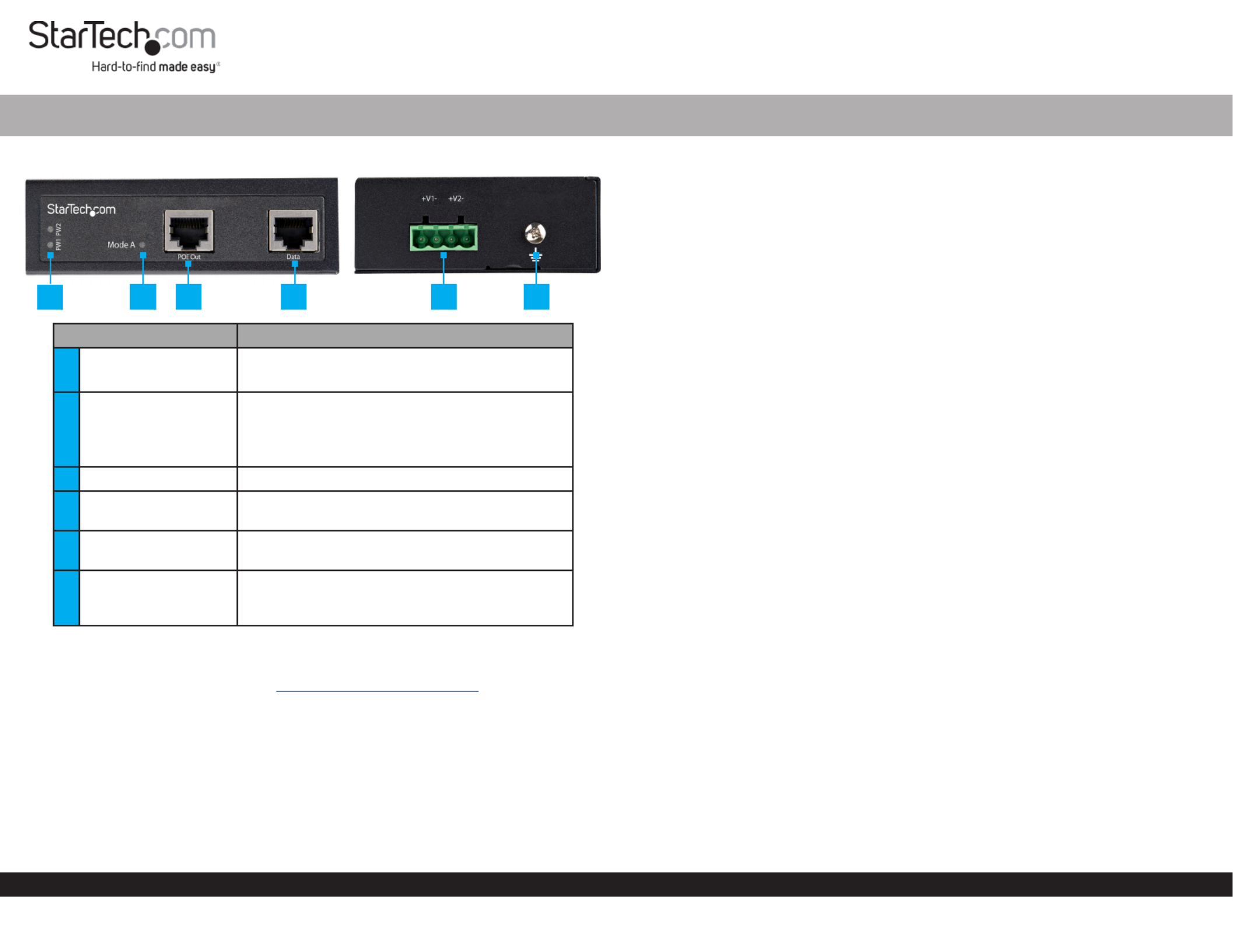
Product Diagram (POEINJ30W)
Component Function
1Power LEDs • A is detected.Green: Power Source
• A is not detected.O: Power Source
2Mode A LED
• Indicates that the Mode A (Green): PoE
Injector is providing power.
• Indicates that the is in idle O: PoE Injector
mode.
3PoE Out Port • Connect a to the .PoE PD Device PoE Injector
4Data Port • Connect a to the Network Switch PoE
Injector.
54-Pin Terminal Block
V1 and V2
• Connect an external (48-56V DC Power Source
DC Input) to the .PoE Injector
6Ground Screw
• Connect a ground connection to the Ground
Screw DC Power Source when connecting a to
the .PoE Injector
Requirements
For the latest requirements, please visit www.startech.com/POEINJ30W
• Small Flat Head Screwdriver x 1
• Writing Utensil x 1
• PoE PD Device x 1
• Network Switch x 1
• DC Power Source or Universal Power Adapter with Type N (OD: 5.5 mm, ID: 2.5 mm)
Barrel Connector x 1
• (Optional) Phillips® Head Screwdriver x 1
• RJ45 Terminated UTP/STP Cat 5e (or better) Network Cable x 2
30W Industrial - Grade Hardened PoE Injector | 1G (1000 Mbps)
Powering the PoE Injector
Terminal Block
Connecting and installing the must be completed by a 4-Wire Terminal Connector
licensed Electrician.
Notes: Make sure that you turn o the power source before connecting the power wire
to the .PoE Injector
Do not exceed the recommend power source voltage as it may result in personal or
product damage.
1. Using a , loosen the two screws, either V1 or V2 on the Small Flat Head Screwdriver
4-Wire Terminal Connector (included).
2. Connect the from a (48 - 56V DC), or the provided Power Wires DC Power Source
Barrel Power Connector Adapter Terminal Block Connectors, to the proper (the
terminals are marked on the . Connect the positive wire to V+ PoE Injector’s Casing)
and the negative wire to V-.
3. Tighten the two screws on the .4-Wire Terminal Connector
4. Insert the in the on the 4-Wire Terminal Connector 4-Wire Terminal Block PoE
Injector.
5. To connect a second to the , repeat steps 1 - 4.Power Source PoE Injector
6. Using a , loosen the on the .Phillips Head Screwdriver Ground Screw PoE Injector
7. Connect the from a to the on the Ground Wire DC Power Source Ground Screw
PoE Injector.
8. Using the , tighten the to secure thePhillips Head Screwdriver Ground Screw
Grounding Wire PoE Injectorto the .
(Optional) Barrel Connector
• Connect a from a Type N (OD: 5.5 mm, ID: 2.5 mm) Barrel Connector Universal
Power Adapter Terminal Block to Barrel Power Connector Adapter. to the
Connecting the PoE Injector
Note: Make sure the total length of the connecting the CAT5e/6 Cable PD Device
to the and the connecting the to the PoE Injector CAT5e/6 Cable PoE Injector
Remote Switch does not exceed 100 meters in total length.
1. Connect a to the on the and the other CAT5e/6 Cable PoE Out Port PoE Injector
end to an RJ45 port on a (e.g. security camera, etc.).PoE PD Device
1 2 3 4 5 6

FCC Compliance Statement
This equipment has been tested and found to comply with the limits for a Class A digital device, pursuant to Part 15 of the FCC
rules. These limits are designed to provide reasonable protection against harmful interference when the equipment is operated
in a commercial environment. This equipment generates, uses and can radiate radio frequency energy and, if not installed
and used in accordance with the instruction manual, may cause harmful interference to radio communications. Operation of
this equipment in a residential area is likely to cause harmful interference in which case the user will be required to correct the
interference at his own expense.
This device complies with part 15 of the FCC Rules. Operation is subject to the following two conditions: (1) This device may not
cause harmful interference, and (2) this device must accept any interference received, including interference that may cause
undesired operation.
Changes or modications not expressly approved by StarTech.com could void the user’s authority to operate the equipment.
Industry Canada Statement
This Class A digital apparatus complies with Canadian ICES-003.
Cet appareil numérique de la classe [A] est conforme à la norme NMB-003 du Canada.
CAN ICES-3 (A)/NMB-3(A)
Use of Trademarks, Registered Trademarks, and other Protected Names and Symbols
This manual may make reference to trademarks, registered trademarks, and other protected names and/or symbols of third-
party companies not related in any way to StarTech.com. Where they occur these references are for illustrative purposes only
and do not represent an endorsement of a product or service by StarTech.com, or an endorsement of the product(s) to which
this manual applies by the third-party company in question. StarTech.com hereby acknowledges that all trademarks, registered
trademarks, service marks, and other protected names and/or symbols contained in this manual and related documents are the
property of their respective holders.
Warranty Information
This product is backed by a two-year warranty.
For further information on product warranty terms and conditions, please refer to .www.startech.com/warranty
Limitation of Liability
In no event shall the liability of StarTech.com Ltd. and StarTech.com USA LLP (or their ocers, directors, employees or agents)
for any damages (whether direct or indirect, special, punitive, incidental, consequential, or otherwise), loss of prots, loss of
business, or any pecuniary loss, arising out of or related to the use of the product exceed the actual price paid for the product.
Some states do not allow the exclusion or limitation of incidental or consequential damages. If such laws apply, the limitations
or exclusions contained in this statement may not apply to you.
Safety Measures
• If product has an exposed circuit board, do not touch the product under power.
Mesures de sécurité
• Si l’un des circuits imprimés du produit est visible, ne pas touchez le produit lorsqu’il est sous tension.
安全対策
• 製品に露出した状態の回路基盤が含まれる場合、電源が入っている状態で製品に触らないでください。
Misure di sicurezza
• Se il prodotto ha un circuito stampato visibile, non toccare il prodotto quando è acceso.
Säkerhetsåtgärder
• Rör aldrig vid enheter med oskyddade kretskort när strömmen är påslagen.
FR: startech.com/fr
DE: startech.com/de
ES: startech.com/es
NL: startech.com/nl
IT: startech.com/it
JP: startech.com/jp
StarTech.com Ltd.
45 Artisans Cres
London, Ontario
N5V 5E9
Canada
StarTech.com Ltd.
Unit B, Pinnacle 15
Gowerton Rd,
Brackmills
Northampton
NN4 7BW
United Kingdom
StarTech.com LLP
2500 Creekside
Parkwy
Lockbourne, Ohio
43137
U.S.A.
8. Using a , tighten the until the Phillips Head Screwdriver Mounting Screws PoE
Injector Wall is securely fasten to the .
Product Dimensions
2. Connect a to the on the and the other end to CAT5e/6 Cable Data Port PoE Injector
an RJ45 port on a .Network Switch
Mounting
DIN Rail Mounting
1. Align the (x 1) with the (x 4) on the side of the DIN Rail Brackets Mounting Holes
PoE Injector.
2. Insert the (x 3) through the and into the Mounting Screws DIN Rail Bracket PoE
Injector.
3. Using a , tighten the . Be careful not to Phillips Head Screwdriver Mounting Screws
over-tighten the .Mounting Screws
4. Clip the onto a , securing the .DIN Rail Bracket DIN Rail PoE Injector
Wall Mounting
It is recommended that you use when wall mounting the .Wall Studs PoE Injector
1. Align the (x 2) with the (x 4) on the side of the Mounting Brackets Mounting Holes
PoE Injector.
2. Insert the (x 4) through each of the and into Mounting Screws Mounting Brackets
the .PoE Injector
3. Align the on the wall in the position you want to mount the PoE Injector PoE
Injector.
4. Using a , mark o both on the .Writing Utensil Mounting Holes PoE Injector
5. Using a , draw a line connecting the two , making sure that the Level Mounting Holes
line is level.
6. Align the on the with the .Mounting Holes PoE Injector Mounting Hole Marks
7. Insert the (x 2) through the on the Mounting Screws Mounting Holes PoE Injector
and into the .Wall
Produktspezifikationen
| Marke: | StarTech.com |
| Kategorie: | Netzwerkkarte/Adapter |
| Modell: | POEINJ30W |
Brauchst du Hilfe?
Wenn Sie Hilfe mit StarTech.com POEINJ30W benötigen, stellen Sie unten eine Frage und andere Benutzer werden Ihnen antworten
Bedienungsanleitung Netzwerkkarte/Adapter StarTech.com

3 Oktober 2024
3 Oktober 2024
1 Oktober 2024
26 September 2024
26 September 2024
26 September 2024
26 September 2024
26 September 2024
26 September 2024
26 September 2024
Bedienungsanleitung Netzwerkkarte/Adapter
- Netzwerkkarte/Adapter Anker
- Netzwerkkarte/Adapter Approx
- Netzwerkkarte/Adapter Asus
- Netzwerkkarte/Adapter Belkin
- Netzwerkkarte/Adapter Gembird
- Netzwerkkarte/Adapter Gigabyte
- Netzwerkkarte/Adapter Hama
- Netzwerkkarte/Adapter Kensington
- Netzwerkkarte/Adapter LogiLink
- Netzwerkkarte/Adapter Manhattan
- Netzwerkkarte/Adapter Maxxter
- Netzwerkkarte/Adapter Nedis
- Netzwerkkarte/Adapter Philips
- Netzwerkkarte/Adapter Sharkoon
- Netzwerkkarte/Adapter Sony
- Netzwerkkarte/Adapter Sweex
- Netzwerkkarte/Adapter Targus
- Netzwerkkarte/Adapter Trust
- Netzwerkkarte/Adapter ZyXEL
- Netzwerkkarte/Adapter Buffalo
- Netzwerkkarte/Adapter Canon
- Netzwerkkarte/Adapter Yamaha
- Netzwerkkarte/Adapter Velleman
- Netzwerkkarte/Adapter Allnet
- Netzwerkkarte/Adapter Devolo
- Netzwerkkarte/Adapter Eminent
- Netzwerkkarte/Adapter Linksys
- Netzwerkkarte/Adapter Netgear
- Netzwerkkarte/Adapter Alecto
- Netzwerkkarte/Adapter König
- Netzwerkkarte/Adapter Renkforce
- Netzwerkkarte/Adapter Kenwood
- Netzwerkkarte/Adapter Pioneer
- Netzwerkkarte/Adapter Klipsch
- Netzwerkkarte/Adapter TERRIS
- Netzwerkkarte/Adapter Vivanco
- Netzwerkkarte/Adapter Abus
- Netzwerkkarte/Adapter Strong
- Netzwerkkarte/Adapter Toshiba
- Netzwerkkarte/Adapter Netis
- Netzwerkkarte/Adapter Ewent
- Netzwerkkarte/Adapter Goobay
- Netzwerkkarte/Adapter Icy Box
- Netzwerkkarte/Adapter Lindy
- Netzwerkkarte/Adapter Thrustmaster
- Netzwerkkarte/Adapter ViewSonic
- Netzwerkkarte/Adapter Lenovo
- Netzwerkkarte/Adapter MSI
- Netzwerkkarte/Adapter Tripp Lite
- Netzwerkkarte/Adapter Mercusys
- Netzwerkkarte/Adapter Marmitek
- Netzwerkkarte/Adapter Lava
- Netzwerkkarte/Adapter ELO
- Netzwerkkarte/Adapter TRENDnet
- Netzwerkkarte/Adapter Sigma
- Netzwerkkarte/Adapter AVM
- Netzwerkkarte/Adapter TP-Link
- Netzwerkkarte/Adapter Alcatel
- Netzwerkkarte/Adapter Black Box
- Netzwerkkarte/Adapter Supermicro
- Netzwerkkarte/Adapter Techly
- Netzwerkkarte/Adapter ESI
- Netzwerkkarte/Adapter NEC
- Netzwerkkarte/Adapter Hercules
- Netzwerkkarte/Adapter Edimax
- Netzwerkkarte/Adapter DrayTek
- Netzwerkkarte/Adapter Totolink
- Netzwerkkarte/Adapter IPEVO
- Netzwerkkarte/Adapter Conceptronic
- Netzwerkkarte/Adapter D-Link
- Netzwerkkarte/Adapter Pinnacle
- Netzwerkkarte/Adapter EVOLVEO
- Netzwerkkarte/Adapter I-Tec
- Netzwerkkarte/Adapter Grixx
- Netzwerkkarte/Adapter QNAP
- Netzwerkkarte/Adapter Icidu
- Netzwerkkarte/Adapter Digitus
- Netzwerkkarte/Adapter Lancom
- Netzwerkkarte/Adapter LevelOne
- Netzwerkkarte/Adapter APC
- Netzwerkkarte/Adapter Cisco
- Netzwerkkarte/Adapter Motu
- Netzwerkkarte/Adapter Tenda
- Netzwerkkarte/Adapter Ubiquiti Networks
- Netzwerkkarte/Adapter UTEPO
- Netzwerkkarte/Adapter Kramer
- Netzwerkkarte/Adapter Intellinet
- Netzwerkkarte/Adapter Eaton
- Netzwerkkarte/Adapter Nexxt
- Netzwerkkarte/Adapter Planet
- Netzwerkkarte/Adapter EnGenius
- Netzwerkkarte/Adapter Simplecom
- Netzwerkkarte/Adapter Twelve South
- Netzwerkkarte/Adapter Emerson
- Netzwerkkarte/Adapter Emtec
- Netzwerkkarte/Adapter Iconbit
- Netzwerkkarte/Adapter Mede8er
- Netzwerkkarte/Adapter Media-tech
- Netzwerkkarte/Adapter Paradigm
- Netzwerkkarte/Adapter Riello
- Netzwerkkarte/Adapter Sitecom
- Netzwerkkarte/Adapter SMC
- Netzwerkkarte/Adapter Steren
- Netzwerkkarte/Adapter AMX
- Netzwerkkarte/Adapter Vivotek
- Netzwerkkarte/Adapter Cudy
- Netzwerkkarte/Adapter Siig
- Netzwerkkarte/Adapter Atto
- Netzwerkkarte/Adapter Moxa
- Netzwerkkarte/Adapter Iogear
- Netzwerkkarte/Adapter AirLive
- Netzwerkkarte/Adapter Dahua Technology
- Netzwerkkarte/Adapter Martin Logan
- Netzwerkkarte/Adapter Microchip
- Netzwerkkarte/Adapter Aluratek
- Netzwerkkarte/Adapter Atlantis Land
- Netzwerkkarte/Adapter J5 Create
- Netzwerkkarte/Adapter ATen
- Netzwerkkarte/Adapter Star Micronics
- Netzwerkkarte/Adapter Axis
- Netzwerkkarte/Adapter Vantec
- Netzwerkkarte/Adapter Digium
- Netzwerkkarte/Adapter Oehlbach
- Netzwerkkarte/Adapter Arctic Cooling
- Netzwerkkarte/Adapter Audac
- Netzwerkkarte/Adapter OSD Audio
- Netzwerkkarte/Adapter Crestron
- Netzwerkkarte/Adapter Extron
- Netzwerkkarte/Adapter CLUB3D
- Netzwerkkarte/Adapter Rocstor
- Netzwerkkarte/Adapter Raidsonic
- Netzwerkkarte/Adapter Satechi
- Netzwerkkarte/Adapter Code Corporation
- Netzwerkkarte/Adapter Xcellon
- Netzwerkkarte/Adapter Hamlet
- Netzwerkkarte/Adapter Tycon Systems
- Netzwerkkarte/Adapter Vivolink
- Netzwerkkarte/Adapter NUVO
- Netzwerkkarte/Adapter Mach Power
- Netzwerkkarte/Adapter Canyon
- Netzwerkkarte/Adapter Perfect Choice
- Netzwerkkarte/Adapter Ernitec
- Netzwerkkarte/Adapter EXSYS
- Netzwerkkarte/Adapter Barox
- Netzwerkkarte/Adapter Altronix
- Netzwerkkarte/Adapter Allied Telesis
- Netzwerkkarte/Adapter Valcom
- Netzwerkkarte/Adapter IC Intracom
- Netzwerkkarte/Adapter 7inova
- Netzwerkkarte/Adapter Raspberry Pi
- Netzwerkkarte/Adapter Microsemi
- Netzwerkkarte/Adapter Luxul
Neueste Bedienungsanleitung für -Kategorien-
16 Oktober 2024
16 Oktober 2024
9 Oktober 2024

5 Oktober 2024

4 Oktober 2024
4 Oktober 2024
3 Oktober 2024

2 Oktober 2024
30 September 2024

28 September 2024