Renault Duster (2009) Bedienungsanleitung
Lesen Sie kostenlos die 📖 deutsche Bedienungsanleitung für Renault Duster (2009) (200 Seiten) in der Kategorie Auto. Dieser Bedienungsanleitung war für 25 Personen hilfreich und wurde von 2 Benutzern mit durchschnittlich 4.5 Sternen bewertet
Seite 1/200

DRIVER’S HANDBOOK
DUSTER

Photo credit: Total/DPPI Imacom group
ELF has developed a complete range of lubricants for RENAULT:
f engine oils
f manual and automatic gearbox oils
Benefiting from the research applied to Formula 1,
lubricants are very high-tech products.
Updated with the help of RENAULT’s technical
teams, this range is perfectly compatible with the
specific features of the brand’s vehicles.
f ELF lubricants enhance
your vehicle’s performance significantly.
RENAULT recommends approved ELF lubricants for oil changes and top-ups.
Contact your RENAULT Dealer or visit www.lubrifiants.elf.com
Warning: to ensure the engine operates optimally, the use
of a lubricant may be restricted to certain vehicles. Please
refer to your maintenance document.
RENAULT recommends ELF
Une marque de

0.1
The descriptions of the models given in this handbook are based on the technical specifications at the time of writing. This hand-
book covers all items of equipment (both standard and optional) available for these models, but whether or not these are
fitted to the vehicle depends on the version, options selected and the country where the vehicle is sold.
This handbook may also contain information about items of equipment to be introduced later in the model year.
Throughout the manual, the “approved dealer” is your DACIA dealer.
Welcome aboard your vehicle
This Driver’s Handbook contains the information necessary:
– for you to familiarise yourself with your vehicle, to use it to its best advantage and to benefit fully from the all the functions and
the technical developments it incorporates.
– to ensure that it always gives the best performance by following the simple, but comprehensive advice concerning regular main-
tenance.
– to enable you to deal quickly with minor faults not requiring specialist attention.
It is well worth taking a few minutes to read this handbook to familiarise yourself with the information and guidelines it contains
about the vehicle and its functions and new features. If certain points are still unclear, our Network technicians will be only too
pleased to provide you with any additional information.
The following symbol will help you when reading this handbook:
Translated from French. Copying or translation, in part or in full, is forbidden unless prior written permission has been obtained from the vehicle manufac-
turer.
To indicate a hazard, danger or safety recommendation.
Enjoy driving your new vehicle.

0.2

0.3
Getting to know your vehicle ...............................
Driving ...................................................................
Your comfort .........................................................
Maintenance .........................................................
Practical advice ....................................................
Technical specifications ......................................
Alphabetical index ...............................................
Sections
1
C O N T E N T S
2
3
4
5
6
7

0.4

1.1
Section 1: Getting to know your vehicle
Keys/Radio frequency remote control . . . . . . . . . . . . . . . . . . . . . . . . . . . . . . . . . . . . . . . . . . . . . . . . 1.2
Locking and unlocking the doors . . . . . . . . . . . . . . . . . . . . . . . . . . . . . . . . . . . . . . . . . . . . . . . . . . . . 1.5
Opening and closing the doors . . . . . . . . . . . . . . . . . . . . . . . . . . . . . . . . . . . . . . . . . . . . . . . . . . . . . 1.7
Engine immobiliser system . . . . . . . . . . . . . . . . . . . . . . . . . . . . . . . . . . . . . . . . . . . . . . . . . . . . . . . . 1.8
Headrests . . . . . . . . . . . . . . . . . . . . . . . . . . . . . . . . . . . . . . . . . . . . . . . . . . . . . . . . . . . . . . . . . . . . . 1.9
Front seats. . . . . . . . . . . . . . . . . . . . . . . . . . . . . . . . . . . . . . . . . . . . . . . . . . . . . . . . . . . . . . . . . . . . . 1.11
Seat belts. . . . . . . . . . . . . . . . . . . . . . . . . . . . . . . . . . . . . . . . . . . . . . . . . . . . . . . . . . . . . . . . . . . . . . 1.12
Methods of restraint in addition to the front seat belts . . . . . . . . . . . . . . . . . . . . . . . . . . . . . . . . . . . . 1.16
Side protection devices . . . . . . . . . . . . . . . . . . . . . . . . . . . . . . . . . . . . . . . . . . . . . . . . . . . . . . . . . . . 1.19
Additional methods of restraint . . . . . . . . . . . . . . . . . . . . . . . . . . . . . . . . . . . . . . . . . . . . . . . . . . . . . 1.20
Child safety: general information . . . . . . . . . . . . . . . . . . . . . . . . . . . . . . . . . . . . . . . . . . . . . . . . . . . . 1.21
mounting a child seat . . . . . . . . . . . . . . . . . . . . . . . . . . . . . . . . . . . . . . . . . . . . . . . . . . . . . . . 1.24
fitting a child seat . . . . . . . . . . . . . . . . . . . . . . . . . . . . . . . . . . . . . . . . . . . . . . . . . . . . . . . . . . 1.26
deactivating/activating the front passenger airbag . . . . . . . . . . . . . . . . . . . . . . . . . . . . . . . . . 1.32
Rear-view mirrors . . . . . . . . . . . . . . . . . . . . . . . . . . . . . . . . . . . . . . . . . . . . . . . . . . . . . . . . . . . . . . . 1.35
Driving position . . . . . . . . . . . . . . . . . . . . . . . . . . . . . . . . . . . . . . . . . . . . . . . . . . . . . . . . . . . . . . . . . 1.36
Instrument panel: warning lights . . . . . . . . . . . . . . . . . . . . . . . . . . . . . . . . . . . . . . . . . . . . . . . . . . . . 1.40
Display and indicators . . . . . . . . . . . . . . . . . . . . . . . . . . . . . . . . . . . . . . . . . . . . . . . . . . . . . . . . . . . . 1.44
On-board computer . . . . . . . . . . . . . . . . . . . . . . . . . . . . . . . . . . . . . . . . . . . . . . . . . . . . . . . . . . . . . . 1.46
Steering wheel, Power-assisted steering . . . . . . . . . . . . . . . . . . . . . . . . . . . . . . . . . . . . . . . . . . . . . 1.50
Clock . . . . . . . . . . . . . . . . . . . . . . . . . . . . . . . . . . . . . . . . . . . . . . . . . . . . . . . . . . . . . . . . . . . . . . . . . 1.51
Audible and visual signals . . . . . . . . . . . . . . . . . . . . . . . . . . . . . . . . . . . . . . . . . . . . . . . . . . . . . . . . . 1.52
Exterior lighting and signals. . . . . . . . . . . . . . . . . . . . . . . . . . . . . . . . . . . . . . . . . . . . . . . . . . . . . . . . 1.54
Adjusting the headlight beam height . . . . . . . . . . . . . . . . . . . . . . . . . . . . . . . . . . . . . . . . . . . . . . . . . 1.56
Windscreen washer/wiper, De-icing . . . . . . . . . . . . . . . . . . . . . . . . . . . . . . . . . . . . . . . . . . . . . . . . . 1.57
Fuel tank (filling with fuel) . . . . . . . . . . . . . . . . . . . . . . . . . . . . . . . . . . . . . . . . . . . . . . . . . . . . . . . . . 1.60

1.2
KEYS, RADIO FREQUENCY REMOTE CONTROL: general information (1/2)
Radio frequency remote
control B
Locking the doors and tailgate.2
3 Unlocking the doors and tailgate.
Coded key for ignition switch, driv-4
er’s door and fuel filler cap.
Key A
Coded key for ignition switch, 1
doors and fuel filler cap.
The key must not be used for any
function other than those described
in the handbook (removing the cap
from a bottle, etc.).
Advice
Avoid leaving the remote control in
hot, cold or humid areas.
Driver’s responsibility
Never leave your vehicle
with the key or remote con-
trol inside and never leave a
child (or a pet) unsupervised, even
for a short while.
The reason for this is that the child
may endanger himself or others by
starting the engine, activating equip-
ment such as the window winders
for example, or locking the doors.
Risk of serious injury.
1
2
3
4
AB

1.3
KEYS, RADIO FREQUENCY REMOTE CONTROL: general information (2/2)
The remote control unit
operating range
This varies according to the environ-
ment. It is therefore important when
handling the remote control to ensure
that you do not lock or unlock the ve-
hicle by inadvertently pressing the but-
tons.
Interference
The presence of certain objects (metal
objects, mobile telephones, or an area
with strong electromagnetic radiation,
etc.) close to the key may create inter-
ference and affect the operation of the
system.
Replacement and additional keys
or remote controls.
You must only contact an approved
Dealer:
– If you need to replace a key it will
be necessary to take the vehicle
and all of its keys to an approved
Dealer in order to initialise the
system.
– depending on the vehicle, you
have the option of using up to
four remote controls.
Remote control unit failure
Make sure that the correct battery
type is being used, and that the
battery is in good condition and in-
serted correctly. These batteries
should have a service life of approx-
imately two years.
Refer to Section 5: “Radio fre-
quency remote control: batteries”
for the battery changing procedure.

1.4
RADIO FREQUENCY REMOTE CONTROL: use
Doors are locked and unlocked using
remote control unit .B
It is powered by a battery which must
be replaced (refer to the information on
the “Radio frequency remote control:
batteries” in Section 5).
Locking the doors
Press locking button .1
The hazard warning lights and side in-
dicator lights to indicate flash twice
that the doors have locked.
If a door or the tailgate is open or not
properly shut, the doors and tailgate
lock then quickly unlock and the hazard
warning lights and side indicator lights
do not flash.
Unlocking the doors
Press unlocking button .2
The hazard warning lights and side in-
dicator lights flash once to indicate that
the doors have unlocked.
1
2
B B

1.5
LOCKING AND UNLOCKING THE DOORS (1/2)
Manual locking
From the outside
Unlock the doors using the remote con-
trol (refer to information on the “Radio
frequency remote control: use” in
Section 1) or using the key in one of the
door locks.
Depending on the vehicle, the key locks
and unlocks the driver’s door or all four
doors.
From the inside
(depending on vehicle)
Push in button to lock and lift button 1 1
to unlock.
Child safety
To make it impossible for the rear doors
to be opened from the inside, move
lever on each door and check from 2
the inside that the doors are securely
locked.
1
2

1.6
LOCKING AND UNLOCKING THE DOORS (2/2)
Electric central locking
Depending on the vehicle, it can be
used to simultaneously lock or unlock
the four doors and the boot. Lock or
unlock the doors by pressing switch .3
The front door mechanism cannot be
locked if the door is open. Driver’s responsibility
If you decide to keep the
doors locked when you are
driving, remember that it
may be more difficult for those as-
sisting you to gain access to the
passenger compartment in the
event of an emergency.
3
3

1.7
OPENING AND CLOSING THE DOORS
Opening from the outside
With the doors unlocked (refer to the
information on “Locking/unlocking the
doors” in Section 1).
Front: place your hand behind handle 1
and pull it towards you..
Rear : (manual opening) lift unlocking
button from the inside and move the 2
door handle.
Opening from the inside
Front: pull handle 3
Rear: from the inside, lift unlocking
button and pull door handle .2 3
Lights-on reminder buzzer
If you have left the lights on after switch-
ing off the ignition, a warning buzzer will
sound when a front door is opened (to
prevent the battery from discharging,
etc.).
As a safety precaution,
the doors should only be
opened or closed when the
vehicle is stationary.
Driver’s responsibility
when parking or stopping
the vehicle
Never leave an animal,
child or adult who is not self-suffi-
cient alone on your vehicle, even for
a short time.
They may pose a risk to themselves
or to others by starting the engine,
activating equipment such as the
electric windows or by locking the
doors.
Also, in hot and/or sunny weather,
please remember that the tempera-
ture inside the passenger compart-
ment increases very quickly.
RISK OF DEATH OR SERIOUS
INJURY.
1
2
3

1.8
ENGINE IMMOBILISER
This prevents the vehicle being
driven by anyone not in possession
of the vehicle’s coded ignition key.
Operating principle
The vehicle is automatically protected
a few seconds after the ignition is
switched off.
If the vehicle does not recognise the
coded ignition key, tell-tale light will 1
flash continuously and the engine
cannot be started.
Any unauthorised work
carried out on the engine
immobiliser (computers,
wiring, etc.) could be dan-
gerous. Work must be carried out
by qualified personnel.
System operation
When the ignition is switched on, tell-
tale lights up continuously for approx-1
imately three seconds and then goes
out. The vehicle has recognised the
code. You can then start the engine.
Vehicle protection
A few seconds after the ignition has
been switched off, tell-tale light will 1
flash constantly.
The vehicle will only be protected after
the ignition has been switched off.
Operating faults
After the ignition has been switched
on, if warning light continues to flash 1
or remains continuously lit, there is a
system operating fault.
In all cases, essential it is to contact
an approved dealer as only they are
qualified to repair the engine immobi-
liser.
If the coded ignition key is faulty,
use the second key (supplied with
the vehicle).
1

1.9
FRONT HEADRESTS
Adjusting the height of headrest A
Press tab and simultaneously slide 1
the headrest to the required position.
To raise the headrests or A B
Depending on the vehicle, press tabs 1
and on the head restraint guides or 2
on button or and lift the headrest to 3 4
release it (tilt the seatback backwards if
necessary).
The headrest is a safety
component. Ensure that it is
fitted and in the correct po-
sition: the top of your head
should be in line with the top of the
headrest.
1
3
To refit headrests A Bor
Insert headrest rods 2 into the holes (tilt
the seatback backwards if necessary).
Push the headrest in until it locks in po-
sition.
2
A
4
B
2
Headrest is fixed and its height B
cannot be adjusted.

1.10
REAR HEADRESTS
Adjusting the height of the
headrests A
Press lock tab and simultaneously 1
slide the headrest to the required po-
sition.
To remove the headrests A
Press the tabs on the catches and 1 4
and remove the headrest.
To remove headrest B
(depending on vehicle)
Simultaneously press the tabs on
catches and on each of the head-2 3
rest rods, then remove the headrest.
Position for using headrest B
(depending on vehicle)
Raise the headrest until it locks to use
it in the high position. Simultaneously
press the tabs on catches and and 2 3
lower the headrest completely.
Storage position for headrest B
(depending on vehicle)
When the headrest is set at the
lowest position, this is for storage
only. It should not be in this position
when a seat is occupied.
The headrest is a safety
component. Ensure that it is
fitted and in the correct po-
sition: the top of your head
should be in line with the top of the
headrest.
To reinstall headrests A
and (depending on the B
vehicle)
Insert the rods into the holes, press the
tabs on both rods and lower the head-
rest.
ABA
A
BA
1 2 3 1 44

1.11
FRONT SEATS
To move forwards or
backwards
Lift bar to release. Release the bar 1
once the seat is in the correct position
and ensure that the seat is fully locked
into position.
To raise or lower the driver’s
seat surface
Depending on the vehicle, lift lever , 2
adjust the seat base to the desired
height, then release the lever.
For safety reasons, carry
out any adjustments when
the vehicle is not being
driven.
We would advise you not to recline
the seatbacks too far to ensure that
the effectiveness of the seat belts is
not reduced.
Make sure that the seatbacks are
correctly locked in place.
Nothing should be placed on the
floor (area in front of driver) as such
objects may slide under the pedal
during braking manoeuvres, thus
obstructing its use.
4
1
2
3
Heated seats
Depending on the vehicle, with the igni-
tion on, press switch .3
The system, which has a thermostat,
decides whether or not the heating is
needed.
To tilt the seatback
Depending on the vehicle, move the
handle or control knob and tilt the 4
seatback to the desired position.

1.12
SEAT BELTS (1/4)
Always wear your seat belt when trav-
elling in your vehicle. You must also
comply with the legislation of the par-
ticular country you are in.
Incorrectly adjusted or
twisted seat belts may
cause injuries in the event
of an accident.
The seatbelt is for the use of one
person only, whether adult or child.
Even pregnant women should wear
a seat belt. In this case, ensure that
the lap belt is not exerting too much
pressure on the abdomen, but do
not allow any slack.
Before starting, adjust your driving
position and then have each occu-
pant adjust their seat belt to ensure
optimum protection.
Adjusting your driving position
(depending on the vehicle)
– Sit well back in your seat (having
removed your coat or jacket etc.).
This is essential to ensure your back
is positioned correctly;
– adjust the distance between the seat and the pedals. Your seat
should be as far back as possible
while still allowing you to depress
the clutch pedal fully. The seatback
should be adjusted so that your arms
are slightly bent when you hold the
steering wheel;
– adjust the position of your head-
rest. For the maximum safety, your
head must be as close as possible to
the headrest;
– adjust the height of the seat. This
adjustment allows you to select the
seat position which offers you the
best possible view;
– adjust the position of the steering
wheel.
Adjusting the seat belts
Sit with your back firmly against the
seatback.
Shoulder strap should be as close as 1
possible to the base of the neck but not
on it.
Lap belt must be worn flat over the 2
thighs and against the pelvis. The seat
belt must be worn as close to the body
as possible. i.e.: avoid wearing heavy
clothing or keeping bulky objects under
the belts, etc.
1
2
Make sure that the rear bench seat
is locked in position correctly so that
the rear seat belts will operate effi-
ciently. Refer to the information on
the “Rear bench seat: functions” in
Section 3.

1.13
SEAT BELTS (2/4)
To fasten
Unwind the belt slowly and smoothly
and ensure that buckle locks into 4
catch 6 (check that it is locked by pulling
on buckle ). If it jams, allow it to return 4
before attempting to unwind it again. If
your seat belt is completely jammed,
pull slowly, but firmly so that just over
3 cm unwinds. Allow it to return slightly
before attempting to unwind it again.
If there is still a problem, contact an ap-
proved dealer.
Adjusting the front seat belt
height
(depending on the vehicle)
Move button to select the position you 7
require so that chest strap is worn as 3
described above.
Make sure that the seat belt is locked
in position correctly after you have ad-
justed it.
ß
Seat belt reminder light
Depending on the vehicle, it
comes on when the engine is started
if the driver’s seat belt is not fastened.
When the vehicle is being driven, it
comes on and a beep sounds for ap-
proximately 2 minutes until the driver’s
seat belt is fastened.
Unlocking
Press button on catch ; the seat belt 5 6
is wound up by the inertia reel. Guide
the buckle to facilitate this manoeuvre.
3
45
6
6
7

1.14
SEAT BELTS (3/4)
Rear side seat belts
Slowly unwind belt and click buckle 8 9
into red catch .10
Rear centre seat belt A
(depending on vehicle)
Remove buckle from its housing .15 16
Slowly unwind belt and click 14
buckle into black catch .15 12
Fasten sliding buckle into red 13
catch 11.
Insert buckle into housing when-15 16
ever the seat belt is not in use.
Check that the rear seat
belts are positioned and op-
erating correctly each time
the rear seats are moved.
88
99
10 10 11 12
A
A
13
15
16
14

1.15
SEAT BELTS (4/4)
The following information applies to the vehicle’s front and rear seat belts.
– No modification may be made to the component parts of the restraint system (belts and seats and their mountings)
fitted originally. For special operations (e.g. fitting child seats) contact an approved Dealer.
– Do not use devices which allow any slack in the belts (e.g. clothes pegs, clips, etc.): a seat belt which is worn too
loosely may cause injury in the event of an accident.
– Never wear the shoulder strap under your arm or behind your back.
– Never use the same belt for more than one person and never hold a baby or child on your lap with your seat belt around
them.
– The belt should never be twisted.
– Following an accident, have the seat belts checked and replaced if necessary. Always replace your seat belts as soon as
they show any signs of wear.
– Make sure that the buckle is inserted into the appropriate catch.
– Ensure that no objects are placed in the area around the seat belt catch as they could prevent it from being properly se-
cured.

1.16
METHODS OF RESTRAINT IN ADDITION TO THE FRONT SEAT BELTS (1/3)
– Have the entire restraint
system checked following
an accident.
– No operation whatsoever
is permitted on any part of the
system (air bags, electronic con-
trol units, wiring) and the system
components must not be reused
on any other vehicle, even if iden-
tical.
– To avoid premature triggering
of the system which may cause
injury, only qualified Network per-
sonnel are authorisedto work on
the methods of restraint in addi-
tion to the front seat belt.
– The electric trigger system may
only be tested by a specially
trained technician using special
equipment.
– When the vehicle is scrapped,
contact an approved dealer for
disposal of the pretensioner and
airbag gas generators.
Pretensioner
With the ignition switched on, if the
vehicle is subject to a significant fron-
tal impact the system may, depending
on the severity of the impact, trigger a
piston which instantly retracts the seat
belt.
The pretensioner holds the seat belt
against the body, holding the occupant
more securely against the seat, thus in-
creasing the seat belt’s efficiency.
Load limiter
Above a certain level of impact force,
this mechanism is used to limit the force
of the belt against the body so that it is
at an acceptable level.
Depending on the vehicle, they are
composed of:
– seat belt pretensioners;
– chest-level load limiters;
– air bags for the driver and front pas-
senger.
These systems are designed to act in-
dependently or together when the vehi-
cle is subjected to a frontal impact.
Depending on the severity of the
impact, the system can trigger:
– seat belt locking;
– the seat belt pretensioner to hold the
occupant in the seat, and the force
limiter;
– the front air bag.

1.17
METHODS OF RESTRAINT IN ADDITION TO THE FRONT SEAT BELTS (2/3)
Driver’s and passenger air
bags
These may be fitted to the front seats
on the driver and passenger side (loca-
tion ).A
Each air bag system consists of:
– an air bag and gas generator fitted
on the steering wheel for the driver
and in the dashboard for the front
passenger;
– an electronic unit for system monitor-
ing which controls the gas generator
electrical trigger system;
– a special warning light å;
– remote sensors.
The air bag system uses
pyrotechnic principles. This
explains why, when the air
bag inflates, it will gener-
ate heat, produce smoke (this does
not mean that a fire is about to start)
and make a noise upon detonation.
An air bag may inflate immediately,
causing some minor, superficial
grazing to the skin or other discom-
fort.
Operation
This system is only operational when
the ignition is switched on.
If a severe impact occurs, the frontal
air bag(s) inflate(s) rapidly, cushion-
ing the impact of the driver’s head and
chest against the steering wheel and
the front passenger’s head against the
dashboard. The air bag then deflates
immediately so that the passengers are
not impeded in any way when they get
out of the vehicle.
A

1.18
METHODS OF RESTRAINT IN ADDITION TO THE FRONT SEAT BELTS (3/3)
Warnings concerning the driver’s air bag
– Do not modify the steering wheel or the steering wheel boss.
– Do not cover the steering wheel boss under any circumstances.
– Do not attach any objects (badge, logo, clock, telephone holder, etc.) to the steering wheel boss.
– You must not remove the steering wheel (such work must only be performed by trained personnel from our Network).
– When driving, do not sit too close to the steering wheel. Sit with your arms slightly bent (see the information on “Adjusting
your driving position” in Section 1). This will allow sufficient space for the air bag to inflate properly and be fully effective.
Warnings concerning the passenger air bag
– Do not attach or glue any objects (badge, logo, clock, telephone holder, etc.) to the dashboard in the proximity of the air bag
housing.
– Do not place anything between the dashboard and the passenger (pet, umbrella, walking stick, parcels, etc.).
– The passenger must not put his or her feet on the dashboard or seat as there is a risk that serious injuries may occur. In
general, all parts of the body should be kept away from the dashboard (knees, hands, head etc.).
– You should reactivate the passenger air bag as soon as you remove the child seat to ensure the protection of the front pas-
senger in the event of an impact.
A REAR-FACING CHILD SEAT MUST NOT BE FITTED TO THE FRONT PASSENGER SEAT UNLESS
THE RESTRAINT SYSTEMS IN ADDITION TO THE SEAT BELT, I.E. AIR BAG, ARE DEACTIVATED.
(refer to the information on “Child safety: deactivating/activating the front passenger air bag” in Section 1)
All of the warnings below are given so that the air bag is not obstructed in any way when it is deployed and also to pre-
vent the risk of serious injuries caused by items which may be dislodged when the air bag deploys.

1.19
SIDE PROTECTION DEVICES
Side air bags
These air bags may be fitted to the front
seats and are deployed at the sides of
the seats (door side) to protect the oc-
cupants in the event of a severe side
impact.
Warnings concerning the side air bag
– Fitting seat covers: seats equipped with an air bag require covers
specifically designed for your vehicle. Contact an approved dealer to find
out if such covers are available from our Network. The use of any covers
other than those designed for your vehicle (including those designed for an-
other vehicle) may affect the operation of the air bags and reduce your protec-
tion.
– Do not place any accessories, objects, or even pets, between the seatback,
the door and the internal fittings. Do not cover the seatback with objects such
as clothes or accessories. This may prevent the air bag from operating cor-
rectly or cause injury when the air bag is deployed.
– No work or modification whatsoever may be carried out on the seat or internal
fittings, except by qualified personnel from our Network.

1.20
The airbag is designed to complement the action of the seat belt. Both the
airbags and seat belts are integral parts of the same protection system.
It is therefore essential to wear the seat belt at all times. If seat belts are
not worn, the occupants are exposed to the risk of serious injury in the
event of an accident. It may also increase the risk of minor superficial injuries
occurring when the airbag is deployed, although such minor injuries are always
possible with airbags.
If the vehicle should overturn or suffer a rear impact, however severe, the pre-
tensioners and air bags are not always triggered. Impacts to the underside of the
vehicle, e.g. from pavements, potholes or stones, can all trigger these systems.
– No work or modification may be carried out on any part of the whatsoever
driver or passenger air bag system (air bag, electronic unit, wiring, etc.), except
by qualified personnel from our Network.
– To ensure that the system is in good working order and to avoid accidental trig-
gering of the system which could cause injury, only qualified personnel from
our Network may work on the air bag system.
– As a safety precaution, have the air bag system checked if your vehicle has
been involved in an accident, or is stolen or broken into.
– When selling or lending the vehicle, inform the user of these points and hand
over this driver’s handbook with the vehicle.
– When scrapping your vehicle, contact your approved Dealer for disposal of the
gas generator(s).
All of the warnings below are given so that the air bag is not obstructed in any
way when it is inflated and also to prevent the risk of serious injuries caused
by items which may be dislodged when the air bag inflates.
ADDITIONAL METHODS OF RESTRAINT
Operating faults
Indicator light , , lights up when 1å
the ignition is switched on and goes out
after a few seconds.
If it does not light up when the ignition
is switched on, or if it lights up when the
engine is running, it indicates a fault in
the system. In this case, fitting a child
seat in the front passenger seat is
PROHIBITED.
Contact an approved dealer as soon
as possible. Your protection will be re-
duced until this fault is rectified.
1

1.21
CHILD SAFETY: General information (1/2)
Carrying children
Children, and adults, must be correctly
seated and strapped in for all journeys.
The children being carried in your vehi-
cle are your responsibility.
A child is not a miniature adult. Children
are at risk of specific injuries as their
muscles and bones have not yet fin-
ished growing. The seat belt alone
would not provide suitable protection.
Use an approved child seat and ensure
you use it correctly.
A collision at 30 mph
(50 km/h) is the same as fall-
ing a distance of 10 metres.
Transporting a child without
a restraint is the equivalent of allow-
ing him or her to play on a fourth-
floor balcony without railings.
Never travel with a child held in your
arms. In the event of an accident,
you will not be able to keep hold of
the child, even if you yourself are
wearing a seat belt.
If your vehicle has been involved in
a road accident, replace the child
seat and have the seat belts and
ISOFIX fittings checked.
Never leave a child unat-
tended in the vehicle.
Check that your child is
always strapped in and that
the belt or safety harness used is
correctly set and adjusted. Avoid
wearing bulky clothing which could
cause the belts to slacken.
Never let your child put their head or
arms out of the window.
Check that the child is in the correct
position for the entire journey, espe-
cially if asleep.
To prevent the doors being
opened, use the childproof
locks (refer to the informa-
tion on “Locking/unlocking
the doors” in Section 1).

1.22
CHILD SAFETY: General information (2/2)
Using a child seat
The level of protection offered by the
child seat depends on its ability to re-
strain your child and on its installation.
Incorrect installation compromises the
protection it offers the child in the event
of harsh braking or an impact.
Before purchasing a child seat, check
that it complies with the regulations for
the country you are in and that it can
be fitted in your vehicle. Consult an ap-
proved dealer to find out which seats
are recommended for your vehicle.
Before fitting a child seat, read the
manual and respect its instructions. If
you experience any difficulties during
installation, contact the manufacturer
of the equipment. Keep the instructions
with the seat.
Set a good example by always fas-
tening your seat belt and teaching
your child:
– to strap themselves in correctly;
– to always get in and out of the car
at the kerb, away from busy traf-
fic.
Do not use a second-hand child
seat or one without an instruction
manual.
Check that there are no objects in
the vicinity of the child seat which
could impede its operation.
Never leave a child unat-
tended in the vehicle.
Check that your child is
always strapped in and that
the belt or safety harness used is
correctly set and adjusted. Avoid
wearing bulky clothing which could
cause the belts to slacken.
Never let your child put their head or
arms out of the window.
Check that the child is in the correct
position for the entire journey, espe-
cially if asleep.

1.23
Booster cushions
From 15 kg or 4 years, the child can
travel using a booster seat, which will
enable the seat belt to be adapted
to suit his/her size and shape. The
booster seat cushion must be fitted with
guides to position the seat belt on the
child’s thighs rather than the stomach.
It is recommended that you use a seat-
back fitted with a belt strap guide which
can be adjusted in terms of height to
position the seat belt in the centre of
the shoulder. It should never rest on the
neck or over the arm. Choose a bucket
type seat for better side protection.
Forward-facing child seats
The child’s head and abdomen need to
be protected as a priority. A forward-fac-
ing child seat which is firmly attached to
the vehicle will reduce the risk of impact
to the head. Transport your child in a
forward-facing seat with a safety har-
ness or guard depending on the child’s
size. Choose a bucket type seat for
better side protection.
Rear-facing child seats
A baby’s head is, proportionally, heavier
than that of an adult and its neck is very
fragile. Transport the child in this po-
sition for as long as possible (until the
age of 2 at the very least). It supports
the head and neck. Choose a bucket
type seat for better side protection and
replace it as soon as the child’s head
extends past the seat shell.
CHILD SAFETY: choosing a child seat

1.24
CHILD SAFETY: mounting a child seat (1/2)
Attachment via the seat belt
The seat belt must be adjusted to
ensure that it is effective in the event of
harsh braking or an impact.
Ensure that the strap paths indicated
by the child seat manufacturer are re-
spected.
Always check that the seat belt is cor-
rectly fastened by pulling it up, then
pulling it out fully whilst pressing on the
child seat.
Check that the seat is correctly held by
moving it from side to side and back
to front: the seat should remain firmly
fixed.
Check that the child seat has not been
installed at an angle and that it is not
resting against a window.
Attachment with the ISOFIX system
Authorised ISOFIX child seats are ap-
proved in accordance with regulation
ECE-R44 in one of the three following
cases:
– ISOFIX universal 3-point forward-
facing seat;
– ISOFIX semi-universal 2-point seat;
– specific.
For the latter two, check that your child
seat can be installed by consulting the
list of compatible vehicles.
Attach the child seat with the ISOFIX
locks, if these are provided. The ISOFIX
system allows quick, easy, safe fitting.
The ISOFIX system is composed of
2 rings for each rear side seat.
Before using an ISOFIX
child seat that you pur-
chased for another vehicle,
check that its installation is
authorised. Consult the list of ve-
hicles which can be fitted with the
seat from the equipment manufac-
turer.
No modifications may be
made to the component
parts of the restraint system
(seat belts, ISOFIX, seats
and their mountings) originally fitted.
The seat belt must never
be twisted or the tension
relieved. Never pass the
shoulder strap under the
arm or behind the back.
Check that the seat belt has not
been damaged by sharp edges.
If the seat belt does not operate nor-
mally, it will not protect the child.
Consult an approved dealer. Do not
use this seat until the seat belt has
been repaired.
Do not use the child seat
if it may unfasten the seat
belt restraining it: the base
of the seat must not rest on
the buckle and/or catch of the seat
belt.

1.25
The third ring of each side seat is used
to attach the upper strap on some child
seats.
Pass the belt between the seatback
and the luggage compartment cover.
The rings ISOFIX are located be-1
tween the seatback and the seat base
and are clearly visible.
To ensure your child seat can be easily
fitted and locked on rings , use access 1
guides on the child seat.2
The ISOFIX anchorage points have been exclusively designed for child
seats with the ISOFIX system. Never fit a different type of child seat, seat
belt or other objects to these anchorage points.
Check that nothing is obstructing the anchorage points.
If your vehicle has been involved in a road accident, have the ISOFIX anchorage
points checked and replace your child seat.
CHILD SAFETY: mounting a child seat (2/2)
It is essential to use the lug-
gage compartment anchor-
age points or to attach 3 4
the upper belt of the child
seat.
It is forbidden to use other mounting
points to attach this strap.
Attach the hook on the belt to one of the
rings (4x2 version) or (4x4 version).3 4
Pull the belt so that the back of the child
seat comes into contact with the vehicle
seatback.
4
3
1
2

1.26
CHILD SAFETY: fitting a child seat (1/6)
In the front seat
The laws concerning children travel-
ling in the front passenger seat differ in
every country. Consult the legislation in
force and follow the indications on the
diagram on the following page.
Before fitting a child seat in this seat (if
authorised):
– deactivate the front passenger air
bag;
– lower the seat belt as far as possible;
– move the seat as far back as possi-
ble;
– gently tilt the seatback away from
vertical (approximately 25°).
Do not change these settings after the
child seat is installed.
RISK OF DEATH OR
SERIOUS INJURY: before
fitting a child seat in this
seat, check that the air bag
has been deactivated (refer to the in-
formation on “Deactivating the front
passenger air bag” in Section 1).
Some seats are not suitable for fitting
child seats. The diagram on the follow-
ing page shows you how to attach a
child seat.
The types of child seats indicated may
not be available. Before using a differ-
ent child seat, check with the manufac-
turer that it can be fitted.
Fit the child seat in a rear
seat wherever possible.
Check that when installing
the child seat in the vehicle
it is not at risk of coming loose from
its base.
If you have to remove the headrest,
check that it is correctly stored so
that it does not come loose under
harsh braking or impact.
Always attach the child seat to the
vehicle even if it is not in use so that
it does not come loose under harsh
braking or impact.

1.27
Rear centre seat
A child seat may only be fitted in this
seat if it is equipped with an inertia-reel
belt. For any additional information,
contact an approved dealer.
CHILD SAFETY: fitting a child seat (2/6)
For the safety of the child in the for-
ward-facing seat, do not move the seat
in front back past the middle of the
runner, do not tilt the seatback too far
(maximum of 25°) and raise the seat as
much as possible.
Check that the forward-facing child seat
is resting against the back of the vehi-
cle seat and that the headrest of the ve-
hicle is not obstructing its use.
In the rear side seat
A carrycot can be installed across the
vehicle and will take up at least two
seats. Position the child with his or her
feet nearest the door.
Before installing a child seat in the
ISOFIX anchoring points on a rear side
seat, check that the seat belt buckles
are not placed between the two ISOFIX
anchorage points in this seat. If neces-
sary, move the buckle for the seat con-
cerned towards the centre of the vehi-
cle.
Move the front seat as far forward as
possible to install a rear-facing child
seat, then move back the seat in front
as far as it will go, although without al-
lowing it to come into contact with the
child seat.
Make sure that the child
seat or the child’s feet do
not prevent the front seat
from locking correctly.
Please refer to the information on
the “Front seat” in Section 1.

1.28
CHILD SAFETY: fitting a child seat (3/6)
Using a child safety system
which is not approved for
this vehicle will not correctly
protect the baby or child.
They risk serious or even fatal injury.
³ Check the status of the air bag
before fitting a child seat or allowing a
passenger to use the seat.
Vehicles without air bag OR with air bag deactivated
² Seat not suitable for fitting child
seats.
¬ Seat which allows a child seat
with “Universal” approval to be attached
by a seat belt.
− Seat which allows a only rear-
facing seat with “Universal” approval
to be attached with a seat belt.
Only if the seat is equipped with an
inertia-reel belt.
RISK OF DEATH OR
SERIOUS INJURY: before
installing a child/baby seat
on the front passenger seat,
check that the air bag has been de-
activated (refer to “Deactivating the
front passenger air bag” at the end
of the paragraph).
Child seat attached using the ISOFIX
mounting
ü Seat which allows an ISOFIX
child seat to be fitted.
± The rear seats are fitted with
an anchorage point which allows a
forward-facing ISOFIX child seat with
universal approval to be fitted. The an-
chorage points are located under the
luggage compartment carpet and are
indicated by a marking.
The size of the ISOFIX child seat is in-
dicated by a letter:
– A, B and B1: for forward-facing seats
in group 1 (9 to 18 kg);
– C: rear-facing seats in group 1 (9 to
18 kg);
– D and E: shell seat or rear-facing
seats in group 0 or 0+ (less than
13 kg);
– F and G: cots in group 0 (less than
10 kg).
1

1.29
CHILD SAFETY: fitting a child seat (4/6)
Child seat attached using the belt
¬ Seat which allows a child seat
with “Universal” approval to be attached
by a seat belt.
Only if the seat is equipped with an
inertia-reel belt.
Using a child safety system
which is not approved for
this vehicle will not correctly
protect the baby or child.
They risk serious or even fatal injury.
² Seat not suitable for fitting child
seats.
Vehicles with passenger air bag not deactivated
RISK OF DEATH OR
SERIOUS INJURY: never
fit a child seat to this seat.
Child seat attached using the ISOFIX
mounting
ü Seat which allows an ISOFIX
child seat to be fitted.
± The rear seats are fitted with
an anchorage point which allows a
forward-facing ISOFIX child seat with
universal approval to be fitted. The an-
chorage points are located under the
luggage compartment carpet and are
indicated by a marking.
The size of the ISOFIX child seat is in-
dicated by a letter:
– A, B and B1: for forward-facing seats
in group 1 (9 to 18 kg);
– C: rear-facing seats in group 1 (9 to
18 kg);
– D and E: shell seat or rear-facing
seats in group 0 or 0+ (less than
13 kg);
– F and G: cots in group 0 (less than
10 kg).
1

1.30
CHILD SAFETY: fitting a child seat (5/6)
(5) RISK OF DEATH OR SERIOUS INJURY: before fitting a child seat on the front passenger seat, check that the air
bag has been deactivated (refer to the information on “Deactivating the front passenger air bag” in Section 1).
(6) RISK OF DEATH OR SERIOUS INJURY: never fit a child seat to this seat.
The table below summarises the information already shown on the diagram on the previous pages, to ensure the regula-
tions in force are respected.
Type of child seat Weight of
the child
Seat
size
Front passenger
seat without air
bag or with air
bag deactivated
(1) (5)
Front passenger
seat with air bag
without deactivation
(1) (6)
Rear
side
seats
Rear centre
seat
(7)
Carrycot fitted across the
vehicle
Approved for group 0
< 10 kg F - G X X U-IL
(2) U
Rear-facing shell seat
Approved for group 0 or 0+
< 13 kg
9 to 18 kg D, E U X U-IL
(3) U
Rear-facing seat
Approved for group 0+ and 1 9 to 18 kg C U X U-IL
(3) U
Forward-facing seat
Approved for group 1 9 to 18 kg A, B,
B1 X X
U - IUF
- IL
(4)
U
Booster seat
Approved for group 2 and 3
15 kg to 25
kg and
22 to 36 kg
– X X U
(4) U

1.31
CHILD SAFETY: fitting a child seat (6/6)
X = Seat not suitable for fitting child seats.
U = Seat which allows a child seat with “Universal” approval to be installed using a seat belt; check that it can be fitted.
IUF = Seat which, on equipped vehicles, allows forward-facing child seats with “Universal” approval to be attached by the ISOFIX
system: check that it can be fitted.
IL = On equipped vehicles, seat which allows an approved “semi-universal” or “vehicle specific” child seat to be attached using the
ISOFIX system; check that it can be fitted.
Refer to the brochure “Child safety equipment” available from the Network to choose the seat suited to your child and
recommended for your vehicle.
(1) Only a rear-facing child seat can be fitted in this seat: raise the seat to the maximum and position it as far back as possible,
tilting the seatback slightly (approximately 25°).
(2) A carrycot can be installed across the vehicle and will take up two seats. Position the child with his or her feet nearest the door.
(3) Move the front seat as far forward as possible to install a rear-facing child seat, then move back the seat in front as far as it will
go, although without allowing it to come into contact with the child seat.
(4) Forward-facing child seat; position the seatback of the child seat in contact with the seatback of the vehicle seat. Adjust the
headrest, or remove it if necessary. Do not push the seat in front of the child more than halfway back on its runners and do not
recline the seatback more than 25°.
(7) A child seat may only be fitted in this seat if it is equipped with an inertia-reel seat belt. For any additional information, please
contact an authorised dealer.

1.32
To deactivate the passenger airbag,
with the ignition off, press and turn
button to the OFF position.1
With the ignition switched back on, it is
essential to check that warning light , 2
], is lit up on the instrument panel.
This warning light remains continu-
ously lit to let you know that you can
fit a child seat.
Deactivating the front
passenger air bag
(depending on vehicle)
To fit a rear-facing child seat on the
front passenger seat, you deacti-must
vate the front passenger air bag if your
vehicle is fitted with air bag deactiva-
tion.
2
1
CHILD SAFETY: deactivating/activating the front passenger air bag (1/3)
2

1.33
DANGER
Since front passenger air
bag triggering and the po-
sition of a rear-facing child
seat are incompatible, it is not per-
mitted to fit such a seat in this posi-
tion unless the vehicle is fitted with an
air bag deactivation device. The child
may suffer very serious injuries if the
air bag inflates.
The markings on the dashboard and
on each side of passenger sun visor 3
will remind you of these instructions.
3
The passenger air bag must
be activated or deactivated
with the .ignition off
If handled when the igni-
tion is on, the warning light å
comes on.
Switch the ignition off then on again
to reset the air bag in accordance
with the lock position.
CHILD SAFETY: deactivating/activating the front passenger air bag (2/3)

1.34
Operating faults
It is forbidden to fit a rear-facing child
seat to the front passenger seat if the
air bag activation/deactivation system
is faulty.
Allowing any other passenger to sit in
that seat is not recommended.
Contact your approved dealer as soon
as possible.
Activation of the front
passenger air bag
(depending on vehicle)
You should reactivate the airbag as
soon as you remove the child seat from
the front passenger seat to ensure the
protection of the front passenger in the
event of an impact.
To reactivate the airbag: with the ve-
hicle at a standstill and with the ignition
switched off, press and turn button to 1
the ON position.
With the ignition switched on, it is es-
sential to check that warning light , 2
], is off.
2
CHILD SAFETY: deactivating/activating the front passenger air bag (3/3)
2

1.35
REAR VIEW MIRRORS
Door mirrors with electrical
adjustment:
With the ignition on, move button :1
– position to adjust the left-hand A
door mirror;
– position to adjust the right-hand B
door mirror;
0 is the neutral centre position.
Heated door mirrors
The mirror is de-iced when the rear
screen is de-iced/demisted; refer to
the information on the “Heated rear
screen”.
Interior rear view mirror
Its position can be adjusted. When driv-
ing at night, to avoid being dazzled by
the headlights of the vehicle behind,
depress the little lever located behind
the rear view mirror .3
3
Door mirrors with manual
adjustment
To adjust the mirror, move lever .2
Folding door mirrors
Manually fold the mirror in the direction
of the arrows.
2
0
A
B
1

1.36
DRIVING POSITION, LEFT-HAND DRIVE (1/4)
The fittings described DEPEND ON THE VEHICLE VERSION AND COUNTRY
1234 5 6 7 8 9 10 11 12 13
33 32 31 141516
17
18
28
29
30
27
26
24
25
23 22 21 20 19

1.37
DRIVING POSITION, LEFT-HAND DRIVE (2/4)
Side air vent.1
Stalk for:2
– direction indicator lights,
– exterior lights,
– front fog lights,
– rear fog light,
– horn.
Instrument panel.3
Location for driver’s air bag.4
Windscreen demister outlet.5
Steering column stalk for wind-6
screen and rear screen wash/wipe.
Information readout control.
Ignition switch.7
Radio remote control.8
Centre air vents.9
10 Seat belt reminder light.
Front passenger airbag deactiva-
tion warning light.
11 Location for passenger air bag or
storage compartment.
12 Side window demister.
13 Front passenger air bag activation/
deactivation lock.
14 Glove box.
15 Location for radio or storage com-
partment.
16 Electric front window control.
17 Central window electric locking
control.
18 Hazard warning lights switch.
19 Rear window electric locking con-
trol.
20 ESP control ( version ( )) 4x4 4WD
or blanking cover.
21 Cigar lighter or accessories socket.
22 Location for ashtray or cup holder.
23 ( ) and ( ) mode 4x2 2WD 4x4 4WD
selector or storage compartment.
24 Handbrake.
25 Electric rear-view mirror control.
26 Electric rear window control.
27 Bottle holder
28 Gear lever.
29 Heating and ventilation controls.
30 Heated rear screen control.
31 Headlight beam height adjustment
control.
32 Bonnet release.
33 Fuse box.
The fittings described DEPEND ON THE VEHICLE VERSION AND COUNTRY.

1.38
DRIVING POSITION, LEFT-HAND DRIVE (3/4)
The fittings described DEPEND ON THE VEHICLE VERSION AND COUNTRY
1234 5 6 7 8 9 10 11 12 13
14
1517
30 29 28 27 26 25
23
24
21
22 20
16
19 18

1.39
DRIVING POSITION, LEFT-HAND DRIVE (4/4)
The fittings described DEPEND ON THE VEHICLE VERSION AND COUNTRY.
Side air vent.1
Stalk for:2
– direction indicator lights,
– exterior lights,
– front fog lights,
– rear fog light,
– horn.
Instrument panel.3
Location for driver’s air bag.4
Windscreen demister outlet.5
Steering column stalk for wind-6
screen and rear screen wash/wipe.
Information readout control.
Ignition switch.7
Radio remote control.8
Centre air vents.9
10 Seat belt reminder light.
Front passenger airbag deactiva-
tion warning light.
11 Location for passenger air bag or
storage compartment.
12 Side window demister.
13 Front passenger air bag activation/
deactivation lock.
14 Glove box.
15 Location for radio or storage com-
partment.
16 Hazard warning lights switch.
17 Heated rear screen control.
18 Rear window electric locking con-
trol.
19 ESP control or blanking cover.
20 Cigarette lighter or accessories
socket.
21 Location for ashtray or cup holder.
22 Mode selector ( ), 4x2 2WD 4x4
( ) or storage compartment.4WD
23 Handbrake.
24 Electric rear-view mirror control.
25 Gear lever.
26 Heating and ventilation controls.
27 Electric central locking switch.
28 Beam height adjustment control.
29 Bonnet release control.
30 Fuse box.

1.40
#Engine oil change warning
light
This lights up on the instrument panel
when an oil change is required.
Change the oil or have it changed as
soon as possible.
Only the distance travelled between two
oil changes is taken into account; the
time interval between two oil changes
is not.
The oil should always be changed
when the first threshold is reached, i.e.
either the distance travelled or the inter-
val specified in your vehicle’s mainte-
nance document. This means you may
have to change the oil before the warn-
ing light comes on.
Refer to the information on the “Oil
change” in Section 4.
xAnti-lock braking warning
light
This light comes on when the ignition is
switched on and goes out within three
seconds. If it lights up when you are
driving, it indicates a fault in the anti-
lock braking system.
WARNING LIGHTS (1/4)
The presence and operation of the warning lights DEPEND ON THE EQUIPMENT AND COUNTRY.
If no lights or sounds are ap-
parent, this indicates a fault
in the instrument panel. This
indicates that it is essential
to stop immediately (as soon as traf-
fic conditions allow). Ensure that the
vehicle is correctly immobilised and
contact an approved Dealer.
Warning lights on instrument
panel A
These warning lights require you to
stop immediately, for your own safety,
as soon as traffic conditions allow.
Switch off the engine and do not re-
start it. Contact an approved dealer.
Ú À Ô
D+x
Braking will then be as normal, without
the ABS.
Contact an approved dealer as soon as
possible.
kDipped beam headlight tell-
tale light
áMain beam headlight tell-tale
light
åAir bag warning light
This comes on when the
engine is started and goes out after a
few seconds.
If it does not come on when the igni-
tion is switched on, or comes on when
the engine is running, there is a fault in
the system.
Contact an approved dealer as soon as
possible.
A

1.41
WARNING LIGHTS (2/4)
If not, switch off the engine and allow
it to cool before checking the coolant
level and the cleanliness of the radiator.
If the level is normal, this indicates an-
other fault. Consult an approved dealer.
ÀOil pressure warning light
This goes out as soon as the
engine starts; if it lights up while driv-
ing, stop immediately and switch off the
ignition. Check the oil level.
If the level is normal, something else is
the cause. Contact an approved dealer.
êEngine immobiliser system
warning light
This light performs several functions.
Refer to the information on the “Engine
immobiliser” in Section 1.
6Electronic fault or diesel
preheating warning light
With the ignition switched on,
this light comes on; it indicates that the
heater plugs are operating.
It goes out after preheating is sufficient
and the engine can be started.
If it remains lit or comes on when you
are driving, it indicates an electrical or
electronic fault. Contact an approved
dealer as soon as possible.
ÒElectronic fault warning
light, petrol versions
If it remains lit or comes on when you
are driving, it indicates an electrical or
electronic fault. Contact an approved
dealer as soon as possible.
ÚBattery charge warning light
It should go out as soon as the
engine starts.
If it comes on when you are driving, it
indicates that the circuit is overcharging
or has discharged. Stop and contact an
approved Dealer.
ùESP warning light
Refer to the information on the
“Electronic stability program (ESP) with
understeer control and traction control
(ASR)” in Section 2.
The presence and operation of the warning lights DEPEND ON THE EQUIPMENT AND COUNTRY.
’4-wheel drive mode indica-
tor light
Refer to the information on “4WD Lock
mode” in Section 2.
‘2-wheel drive mode indica-
tor light
Refer to the information on “2WD
mode” in Section 2.
VRear screen de-icing/de-
misting indicator light
LLow fuel level warning light
It comes on when the engi-
neis started then goes out after three
seconds. If it stays on, fill up with fuel
assoon as possible.
dDirection indicator tell-tale
light
ÔCoolant temperature warn-
ing light
This goes out as soon as the engine
starts. If it comes on when driving, it in-
dicates an increase in the coolant tem-
perature. Stop and let the engine idle
for a minute or two; the temperature
should fall.

1.42
WARNING LIGHTS (3/4)
The presence and operation of the warning lights DEPEND ON THE EQUIPMENT AND COUNTRY.
ÄToxic Fume Filter System
Warning Light
It comes on when the ignition is
switched on and then goes out.
– If it comes on continuously, consult
an approved dealer as soon as pos-
sible.
– If it flashes, reduce the engine speed
until the light stops flashing. Contact
an approved dealer as soon as pos-
sible.
Refer to the information “Advice on
antipollution, fuel economy and driving”
in Section 2.
DHandbrake on and brake cir-
cuit incident warning light
If it lights up, check that the hand brake
is fully released. If not, it indicates that
the fluid level is low in one of the cir-
cuits. It may be dangerous to continue
driving, contact an approved dealer.
fRear fog light tell-tale
ÆSTOP light
This lights up when the ignition
is switched on and goes out as soon as
the engine is started. It lights up at the
same time as other warning lights, and
is accompanied by a beep.
It requires you to stop immediately, for
your own safety, as soon as traffic con-
ditions allow.
Switch off the engine and do not restart
it.
Consult an approved dealer.
gFront fog light tell-tale
^Water in the diesel filter
warning light
If it remains lit or comes on while driv-
ing, it indicates that water is present in
the diesel filter. Contact an approved
dealer as soon as possible.
ÅDoor status warning light
This indicates the status of the doors
(or tailgate).
ÜNot used
îNot used

1.43
WARNING LIGHTS (4/4)
The presence and operation of the warning lights DEPEND ON THE EQUIPMENT AND COUNTRY.
Warning lights on console B
]Front passenger air bag de-
activation warning light.
Refer to the information on “Child
Safety” in Section 1.
ßFront seat belt reminder
warning light
This warning light comes on continu-
ously on the centre console when the
engine is started. If one of the seat belts
affected is not fastened, the light stays
on then, when the vehicle reaches
a speed of approximately 6 mph
(10 km/h), it flashes and a beep sounds
for approximately 90 seconds.
BB

1.44
DISPLAY AND INDICATORS (1/2)
Rev counter (rpm × 1 000) Speedometer (km or miles 1 2
per hour)
Overspeed buzzer
Depending on the vehicle, a buzzer
sounds for approximately 10 seconds
every 30 seconds, as long as the ve-
hicle is travelling in excess of 72 mph
(120 km/h).
12
Fuel gauge 3
The number of squares lit shows the
fuel level. When it is at minimum, the
squares disappear and the low fuel
level warning light comes on.
3
In ( ) mode on rough ter-4x4 4WD
rain, there is a risk that incorrect in-
formation on the fuel level may be
displayed. Wait until you are on flat
ground again for a stable reading of
the oil level squares.

1.45
DISPLAY AND INDICATORS (2/2)
Coolant temperature
indicator 4
The number of squares lit depends on
the engine coolant temperature. There
is no warning unless the last three
squares light up.
Multifunction display A
Total mileage recorder, distance trav-
elled trip mileometer, clock.
OR
Trip computer and warning
system
Refer to the information on the “Trip
computer and warning system” in
Section 1.
Multifunction key 5
– Display selection
By pressing the button you can shift
from the total mileage recorder, trip
mileometer and time or vice-versa.
– Resetting the trip mileage re-
corder
Once the trip mileage display is se-
lected, press and hold the button.
– Resetting the clock
Refer to the information on the
“Clock” in Section 1.
4
5
A

1.46
TRIP COMPUTER AND WARNING SYSTEM (1/4)
Display 1
General reset and trip
mileage recorder reset key 2
To reset the trip mileage recorder, the
display must show the Trip mileometer
function.
Press and hold button .2
Display selection key 3
Keep pressing key briefly to scroll 3
through the following information (de-
pending on the vehicle) in sequence:
a) total mileage recorder,
b) trip mileage recorder,
c) fuel used,
d) average consumption,
e) estimated range,
f) distance travelled,
g) average speed.
Refer to the table on the following
pages showing display examples.
The information display DEPENDS ON THE VEHICLE EQUIPMENT AND COUNTRY.
1
2
3

1.47
Interpreting some of the
values displayed after
resetting
The values showing average fuel con-
sumption, range and average speed
will become more stable and reliable
the further you travel after pressing the
reset button.
For the first few miles after pressing the
reset key you will notice that the range
increases as you travel. This range
takes into account the average fuel con-
sumption since the last time the reset
button was pressed. Therefore, the fuel
consumption may decrease when:
– the vehicle stops accelerating,
– the engine reaches its operating
temperature (engine cold when
reset button pressed),
– when driving from a built-up area
onto the open road.
Therefore, if the average fuel con-
sumption decreases, the range
will increase.
The information display DEPENDS ON THE VEHICLE EQUIPMENT AND COUNTRY.
– You may also notice that the aver-
age fuel consumption increases
when the vehicle is stationary and
the engine idling.
This is normal, since the computer
takes account of fuel used during
idling.
Manually resetting the journey pa-
rameters: with the display showing
one of the journey parameters, press
button 2 until the display is reset.
Automatically resetting the journey
parameters: the reset is automatic
when the capacity of one of the memo-
ries is exceeded.
TRIP COMPUTER AND WARNING SYSTEM (2/4)

1.48
TRIP COMPUTER AND WARNING SYSTEM (3/4)
The information display DEPENDS ON THE VEHICLE EQUIPMENT AND COUNTRY.
Examples of display
selections by repeatedly
pressing 3 Interpreting the display
a) Total mileage recorder.
b) Trip mileage recorder.
c) Fuel used since the last time the reset button was pressed.
d) Average fuel consumption since the last time the reset button was pressed.
This value is displayed after driving 400 metres and takes into account the
distance travelled and the fuel used since the last time the reset button was
pressed.

1.49
TRIP COMPUTER AND WARNING SYSTEM (4/4)
The information display DEPENDS ON THE VEHICLE EQUIPMENT AND COUNTRY.
Examples of display
selections by repeatedly
pressing 3 Interpreting the display
e) Estimated range with remaining fuel
This range takes into account the average fuel consumption since the last time
the reset button was pressed.
The value is displayed after driving around 400 metres.
f) Distance travelled since the last reset.
g) Average speed since the last reset.
The value is displayed after driving around 400 metres.

1.50
STEERING WHEEL, POWER-ASSISTED STEERING
Power Assisted Steering
With the engine running, do not leave
the steering wheel at full lock while sta-
tionary as this may damage the power-
assisted steering pump.
With the engine switched off, or if there
is a system fault, it is still possible to
turn the steering wheel. The force re-
quired will be greater.
Adjusting the steering wheel
Depending on the vehicle, the steering
wheel position is adjustable.
Lift lever and place the steering wheel 1
in the required position; raise the lever
to lock the steering wheel in place.
Make sure that the steering wheel is
correctly locked.
For safety reasons, only
adjust the steering wheel
when the vehicle is station-
ary.
Never switch off the igni-
tion when travelling down-
hill, and avoid doing so in
normal driving (assistance
is not provided).
1

1.51
CLOCK
Resetting the clock
With the ignition on, select display 1
showing total mileage and clock.
There are two ways to set the time:
– Pressing and holding button 2 allows
you to scroll through the hours and
minutes quickly;
– short presses on button allow you 2
to set the time minute by minute.
If the electrical supply is cut (battery
disconnected, broken supply wire,
etc.), the clock will lose its time set-
ting.
The clock must be reset.
For your safety, we recom-
mend that you do not adjust
the clock while driving.
2
1

1.52
AUDIBLE AND VISUAL SIGNALS (1/2)
Horn
Press the end of the stalk .1
Depending on the vehicle, press on one
of areas .2
Headlight flasher
Pull stalk towards you to flash the 1
headlights.
1
2
Direction indicators
Move stalk parallel to the steering 1
wheel and in the direction you are going
to turn it.
When driving on the motorway, the
steering wheel is not usually turned suf-
ficiently to return the stalk automatically
to its starting position. There is an inter-
mediate position in which the stalk may
be held when changing lanes.
When the stalk is released, it will auto-
matically return to its starting position.
1

1.53
AUDIBLE AND VISUAL SIGNALS (2/2)
33
éHazard warning lights
Press switch .3
This switch activates all four direction
indicators and the side indicator lights
simultaneously.
It must only be used in an emergency to
warn drivers of other vehicles that you
have had to stop in an area where stop-
ping is prohibited or unexpected, or that
you are obliged to drive under special
conditions.

1.54
EXTERIOR LIGHTING AND SIGNALS (1/2)
uSide lights
Turn the end of stalk until the 1
symbol is opposite mark .2
kDipped beam
headlights
Turn the end of stalk until the symbol 1
is opposite mark .2
An indicator light on the instrument
panel will come on.
á
Main beam headlights
With stalk in dipped beam 1
headlights position, move the stalk to-
wards you.
When the main beam headlights are lit
up, an indicator light on the instrument
panel lights up.
To return to the dipped headlight posi-
tion, pull the stalk towards you again.
eSwitching off the lights
Return the end of stalk to its 1
initial position.
Lights-on warning buzzer
A warning buzzer will sound when a
front door is opened and the lights
are left on after the ignition has been
switched off (to prevent discharge of
the battery).
Before driving at night, check that the electrical equipment is operating
correctly and adjust the headlight beams (if your vehicle is not carrying
its normal load).
Check that the lights are not obscured (by dirt, mud, snow or objects
which could cover them).
12
1

1.55
EXTERIOR LIGHTING AND SIGNALS (2/2)
e
Turning off the fog
lights
Turn centre ring again until the symbol 3
for the fog light or for extinction position
is opposite mark .4
The corresponding indicator light on the
instrument panel goes out.
The front and rear fog lights switch off
when the exterior lights are switched
off.
gFront fog lights
Turn the centre ring of stalk 3
until the symbol is opposite mark .4
The fog lights only light up if the exterior
lights have been switched on. An indi-
cator light on the instrument panel then
lights up.
Do not forget to switch off the fog lights
when they are no longer needed, to
avoid inconveniencing other road
users.
hRear fog lights
Turn the centre ring of
stalk until the symbol is opposite 3
mark .4
The fog lights only light up if the exterior
lights have been switched on. An indi-
cator light on the instrument panel then
lights up.
Remember to switch off the these
lights when they are no longer required
to avoid inconveniencing other road
users.
3 4
3

1.56
Examples of positions for adjusting control according to the load A
Driver alone or with front passenger 0
Driver with one front passenger and
one rear passenger 0
Driver with one front passenger and
two rear passengers 1
Driver with one front passenger and
three rear passengers 1
Driver with one front passenger,
three rear passengers and luggage 2
Driver with one front passenger and
luggage 3
ADJUSTING THE BEAM HEIGHT
Control is used to adjust the height A
of the headlight beams according to the
load.
Turn control anticlockwise to lower A
the beams and clockwise to raise them.
A

1.57
WINDSCREEN WASHER/WIPER, DE-ICING (1/3)
nWindscreen wiper
With the ignition on, move
stalk around the steering wheel:1
A Park.
B Intermittent wiping.
The wipers will pause for several
seconds between sweeps.
C Normal wiping speed.
D Fast wiping speed.
s
Windscreen wiper
With the ignition on, pull stalk 1
towards you.
A brief pull will trigger a single sweep
of the wipers, in addition to the wind-
screen washer.
A longer pull will trigger three sweeps
of the wipers, in addition to the wind-
screen washer.
In frosty weather, make sure that
the wiper blades are not stuck by ice
(risk of motor overheating).
Keep an eye on the condition of the
blades. They should be replaced as
soon as they become less efficient.
This will occur approximately once
a year. Clean your windscreen reg-
ularly.
If you switch off the ignition before
switching off the windscreen wiper
(position ) the blades will stop at A
random on the windscreen.
After switching the ignition back on,
simply move stalk to position to 1 A
place them in the park position.
Before touching the wind-
screen (washing the vehi-
cle, de-icing, cleaning the
windscreen, etc.) move
stalk to position (park). Risk of 1A
injury and/or damage.
When working in the engine
compartment, ensure that
the windscreen wiper stalk
is in position (park). Risk A
of injury.
1
A
B
C
D

1.58
WINDSCREEN WASHER/WIPER, DE-ICING (2/3)
YRear screen wiper
With the ignition on, turn the
end of stalk to align the symbol with 1
mark .2
2
Before using the rear wiper, check
that no object is obstructing the
travel of the blade.
In frosty weather, make sure that
the wiper blades are not stuck by ice
(to avoid the risk of the motor over-
heating).
Keep an eye on the condition of the
blades. They should be replaced as
soon as they become less efficient.
This will occur approximately once
a year. Clean your windscreen reg-
ularly.
p
Rear screen washer/
wiper
With the ignition on, turn the end of
stalk to align the symbol with mark .1 2
When the stalk is released, it returns to
the rear wipe position.
1

1.59
WINDSCREEN WASHER/WIPER DE-ICING (3/3)
VHeated rear screen
With the engine running,
press button (the indicator light on the 3
instrument panel lights up).
This function de-ices/demists the rear
screen and the electric de-icing rear-
view mirrors (depending on the vehi-
cle).
Depending on the vehicle, the function
is stopped:
– automatically after it has been run-
ning for 12 minutes (the indicator
light goes out);
– by pressing button again (the indi-3
cator light goes out).
3
Before touching the wind-
screen (washing the vehi-
cle, de-icing, cleaning the
windscreen, etc.) move
stalk to position (park). Risk of 1A
injury and/or damage.
3

1.60
FUEL TANK (1/3)
Usable capacity of the fuel tank:
50 litres approximately.
Fuel filler cap: this is spe-
cific to the vehicle type. If
you have to replace it, make
sure the new cap is of the
same type. Contact an approved
dealer.
Never place the cap near a source
of heat or flame.
Do not wash the filler area with a
high-pressure washer.
A
1
To open fuel flap , insert your finger in A
recess .B
To close, push the fuel filler flap by A
hand as far as it will go. Depending
on the vehicle, the cap is unlocked 1
using the ignition key. If not, it will be
connected to the vehicle by a strip of
plastic. For details on filling the fuel
tank, please refer to the information on
“Filling with fuel”.
There is a cap holder on the fuel filler 2
flap for holding the cap when the tank is
being filled.
2
C
B

1.61
FUEL TANK (2/3)
Vehicles running on ethanol-based
fuel
Always use unleaded petrol or fuel
containing a maximum of 85 percent
ethanol (E85).
In very cold conditions, it may be very
difficult or even impossible to start the
engine.
Note: you may notice an increase in
fuel consumption with this type of fuel.
When the fuel is changed the engine
must adjust, which may cause minor in-
conveniences for a few minutes (longer
starting times, cutting out, etc.).
Fuel grade
Always use a high-grade fuel that
complies with the legislation in force
in each country. It must conform to the
specifications given on label inside C
the fuel filler flap.
Refer to the “Engine specifications”
table in Section 6.
Petrol version
It is essential to use unleaded petrol.
The octane rating (RON) must conform
to the specifications given on the label
inside fuel filler flap .C
Diesel versions
It is essential to use diesel fuel that con-
forms to the specifications given on the
label inside fuel flap .C
Filling with fuel
Insert the nozzle to open valve and A
insert it before turning it on to fill fully
the fuel tank (risk of splashing).
Keep the nozzle in this position
throughout the entire filling operation.
When the pump cuts out automatically
at the end of the filling procedure, a
maximum of two further filling attempts
may be made, as there must be suffi-
cient space in the fuel tank to allow for
expansion.
Make sure that no water enters the fuel
tank during filling. The valve and its A
surround must remain clean.
Petrol versions
Using leaded petrol will damage the
antipollution system and may lead to a
loss of warranty.
To ensure that the fuel tank is not filled
with leaded petrol, the fuel tank filler
neck contains a restrictor fitted with a
foolproof system which only allows
the nozzle for unleaded petrol to be
used (at the pump).
Do not mix even small
amounts of petrol (un-
leaded or E85) with diesel.
Do not use ethanol-based
fuel if your vehicle is not compatible
with this fuel.
Do not add additive to the fuel other-
wise you risk damaging the engine.

1.62
Persistent smell of fuel
If you notice a persistent
smell of fuel you should:
– stop the vehicle as soon
as traffic conditions allow and
switch off the ignition;
– switch on the hazard warning
lights and ask your passengers to
leave the vehicle and stay clear
of the traffic;
– contact an approved Dealer.
No modifications what-
soever are permitted on
any part of the fuel supply
system (computers, wiring,
fuel circuit, injector, protection
covers, etc.) as this may be danger-
ous (such work must be undertaken
by qualified Network personnel).
Priming bulb
(diesel version)
After a breakdown caused by com-
pletely running out of fuel, the system
must be reprimed before the engine is
restarted:
Note: the bulb is always located on the
right-hand side of the engine compart-
ment.
Work bulb until the fuel runs into 2
pipe .1
If the engine does not start after several
attempts, contact an approved dealer.
The engine may be hot
when working in close prox-
imity. In addition, the engine
cooling fan may come on at
any moment.
Risk of injury.
FUEL TANK (3/3)
12

2.1
Section 2: Driving
(Advice on use relating to fuel economy and the environment)
Running in, Ignition switch . . . . . . . . . . . . . . . . . . . . . . . . . . . . . . . . . . . . . . . . . . . . . . . . . . . . . . . . . 2.2
Starting, stopping the engine . . . . . . . . . . . . . . . . . . . . . . . . . . . . . . . . . . . . . . . . . . . . . . . . . . . . . . . 2.3
Special features of petrol versions . . . . . . . . . . . . . . . . . . . . . . . . . . . . . . . . . . . . . . . . . . . . . . . . . . 2.4
Special features of diesel versions . . . . . . . . . . . . . . . . . . . . . . . . . . . . . . . . . . . . . . . . . . . . . . . . . . 2.5
Recommendations: emission control, fuel economy and driving. . . . . . . . . . . . . . . . . . . . . . . . . . . . 2.6
Environment . . . . . . . . . . . . . . . . . . . . . . . . . . . . . . . . . . . . . . . . . . . . . . . . . . . . . . . . . . . . . . . . . . . 2.9
Gear lever, Handbrake . . . . . . . . . . . . . . . . . . . . . . . . . . . . . . . . . . . . . . . . . . . . . . . . . . . . . . . . . . . 2.10
Transmission: 4-wheel drive (4WD) . . . . . . . . . . . . . . . . . . . . . . . . . . . . . . . . . . . . . . . . . . . . . . . . . 2.11
Driver correction devices and aids . . . . . . . . . . . . . . . . . . . . . . . . . . . . . . . . . . . . . . . . . . . . . . . . . . 2.15
Automatic gearbox. . . . . . . . . . . . . . . . . . . . . . . . . . . . . . . . . . . . . . . . . . . . . . . . . . . . . . . . . . . . . . . 2.19

2.2
Petrol version
For the first , do 600 miles (1,000 km)
not exceed 78 mph (130 km/h) in the
highest gear, or 3,000 to 3,500 rpm.
You may only expect top performance
from your vehicle after approximately
1,800 miles (3,000 km).
Service intervals: refer to the
Maintenance Service Booklet for the
vehicle.
Diesel version
For the first , do 900 miles (1,500 km)
not exceed 2,500 rpm. After complet-
ing this mileage you may drive faster,
although you may only expect top per-
formance after approximately 3,600
miles (6,000 km).
Do not accelerate hard while the engine
is still cold and do not let the engine
over-rev.
Service intervals: refer to the
Maintenance Service Booklet for the
vehicle.
RUNNING IN, IGNITION SWITCH
Stop and steering lock
position St
To lock: remove the key and turn the
steering wheel until the steering column
locks.
To unlock: turn the key and the steering
wheel slightly.
Accessories position A
When the ignition is switched off, any
accessories (radio, etc.) will continue to
function.
Ignition on position M
The ignition is switched on:
– the engine may be petrol version:
started.
– the engine is pre-diesel version:
heating.
Start position D
If the engine fails to start at the first
attempt, the key must be turned back
before the starter can be activated
again.
Release the key as soon as the engine
starts.

2.3
Petrol injection
Engine warm or cold
– Turn the key to the start position
without depressing the accelera-
tor.
– Release the key as soon as the
engine starts.
É
Diesel injection
Turn the ignition key to ignition “On” po-
sition , and hold this position until the M
preheating warning light goes out.
Turn the key to starter position D with-
out depressing the accelerator
pedal.
Release the key as soon as the engine
starts.
Stopping the engine
With the engine idling, turn the key
back to “Stop” position .St
Starting the engine
In very cold conditions (temperatures
below –20°C): so that it is easier to
start the engine, switch on the ignition
for several seconds starting the before
engine.
Make sure the engine immobiliser is not
activated. Refer to the information on
the “Engine immobiliser” in Section 1.
STARTING/STOPPING THE ENGINE
Never leave your vehicle with the key or remote control inside and never leave a child (or a pet) unsupervised, even
for a short while.
The reason for this is that the child may endanger himself or others by starting the engine, activating equipment such
as the window winders for example, or locking the doors.
Risk of serious injury.
Never switch off the ignition before the vehicle has stopped completely. Once the engine has stopped, the brake servo,
power assisted steering and passive safety equipment such as air bags will no longer operate.
The steering is locked when the key is removed.

2.4
SPECIAL FEATURES OF PETROL VERSIONS
The following operating conditions:
– driving for long periods when the low
fuel level warning light is lit;
– using leaded petrol;
– using oil or fuel additives which are
not approved by the manufacturer.
Or operating faults such as:
– faulty ignition system, running out of
fuel or disconnected spark plugs re-
sulting in the engine misfiring or cut-
ting out when driving;
– loss of power,
may cause the catalytic converter to
overheat, reducing its efficiency which
may irreparably damage it and cause
heat damage to the vehicle.
If you notice any of the above operating
faults, have the necessary repairs car-
ried out as soon as possible by an ap-
proved Dealer.
These faults may be avoided by reg-
ularly taking your vehicle to your ap-
proved dealer at the intervals speci-
fied in your Maintenance Service
Document.
Starting problems
To avoid damaging the catalytic con-
verter, keep trying to start the do not
engine (using the start button, or by
pushing or towing the vehicle) without
having identified and corrected the
starting fault.
If the fault cannot be identified, do not
continue to try and start the engine, but
contact an approved dealer.
Do not park the vehicle or
run the engine in locations
where combustible sub-
stances or materials such
as grass or leaves can come into
contact with a hot exhaust system.

2.5
SPECIAL FEATURES OF DIESEL VERSIONS
Diesel engine speed
Diesel engines are fitted with an injec-
tion pump which prevents the engine
speed being exceeded irrespective of
the gear selected.
If the Ä Ò and warning lights
come on, consult an approved dealer
as soon as possible.
When driving, depending on the fuel
grade used, it is possible that white
smoke may be emitted.
This is due to the exhaust particle filter
being cleaned automatically, and does
not affect the way the vehicle runs.
Running out of fuel
If the tank has been completely
drained, the system must be reprimed
after the tank is refilled: see information
on the “Fuel tank” in Section 1 before
restarting the engine.
Precautions to be taken in
winter
To avoid any faults in icy weather:
– ensure that the battery is always fully
charged;
– always keep the diesel tank rela-
tively full to avoid water vapour con-
densing in it and accumulating at the
bottom of the tank.
Do not park the vehicle or
run the engine in locations
where combustible sub-
stances or materials such
as grass or leaves can come into
contact with a hot exhaust system.

2.6
By virtue of its design, moderate fuel
consumption and initial settings, your
vehicle conforms to current antipol-
lution regulations. The manufacturer
is actively striving to reduce pollutant
exhaust gas emissions and to save
energy. But the fuel consumption of
your vehicle and the level of pollutant
exhaust gas emissions are also your
responsibility. Ensure that it is main-
tained and used correctly.
Maintenance
It should be noted that failure to respect
antipollution regulations may lead to
legal action being taken against the
vehicle owner. In addition, replacing
engine, fuel supply system and exhaust
components with parts other than those
originally recommended by the manu-
facturer may alter your vehicle so that
it no longer complies with antipollution
standards. Have your vehicle adjusted
and checked by an authorised dealer,
in accordance with the instructions
given in your maintenance schedule:
they will have all the equipment nec-
essary for ensuring that your vehicle is
maintained to its original standard.
Engine adjustments
Air filter, diesel filter: a choked ele-
ment hinders performance. It must be
replaced.
Exhaust gas monitoring system
The exhaust gas monitoring system will
detect any operating faults in the vehi-
cle’s antipollution system.
If this system malfunctions, toxic sub-
stances may be released into the at-
mosphere or damage may occur.
ÄThis warning light on the in-
strument panel will indicate if
there are any faults in the system:
This lights up when the ignition is
switched on and goes out when the
engine is started.
– If it lights up continuously, consult an
approved Dealer as soon as possi-
ble;
– if it flashes, reduce the engine speed
until the light stops flashing. Contact
your approved dealer as soon as
possible.
ADVICE: antipollution, fuel economy and driving (1/3)

2.7
Driving
– Drive carefully for the first few miles
until the engine reaches its normal
operating temperature, rather than
let it warm up while the vehicle is sta-
tionary.
– Speed is expensive.
– Sporty driving uses a lot of fuel: drive
with a light right foot.
– Brake as little as possible. If you an-
ticipate an obstacle or bend in ad-
vance, you may then simply release
the accelerator pedal.
– Avoid sudden acceleration.
ADVICE: antipollution, fuel economy and driving (2/3)
– Double declutching and accelerating
before switching off are unnecessary
in modern vehicles.
– Do not try to maintain the same
speed up a hill, accelerate no more
than you would on the level. Keep
your foot in the same position on the
accelerator pedal.
– Do not overrev the engine in the in-
termediate gears. Always use the
highest gear possible without labour-
ing the engine.
On versions with an automatic gear-
box, it is preferable to keep the gear
lever in position .D
Your vehicle has a greater
ground clearance than an
ordinary passenger vehicle.
This gives it a higher centre
of gravity, making it more suscepti-
ble to rolling during sudden or ag-
gressive manoeuvres, or when cor-
nering at high speeds.
Take extra care when the vehicle is
loaded (in particular when the load
is on the roof).
Ensure that all passengers are
wearing their seat belts.
A label affixed to the sun visor re-
minds you of this.
Vehicles with 4x4 (4WD) trans-
mission
On flat, level ground, with the vehi-
cle unladen, you are recommended
to start in second gear.
Driving problems
On the driver’s side, only
use mats specially adapted
for the vehicle and attached
to prefitted devices. Check regularly
to make sure they are secure. Do
not overlay several mats.
Risk of pedals jamming.

2.8
ADVICE: antipollution, fuel economy and driving (3/3)
– In vehicles fitted with air condi-
tioning, it is normal to observe an
increase in fuel consumption (es-
pecially in urban conditions) when
it is used. For vehicles fitted with
manual air conditioning, switch off
the system when it is not required.
Advice for reducing consumption
and therefore helping to preserve
the environment:
If the vehicle has been parked in the
sun, open the doors for a few mo-
ments to let the hot air escape before
starting the engine.
– Never fill the fuel tank right to the
brim to avoid overflow.
– Do not leave an empty roof rack
fitted to the vehicle.
– It is better to fit a trailer for bulky ob-
jects.
– When towing a caravan, fit a wind
deflector and adjust it carefully.
Advice on use
– Electricity is fuel; switch off all the
electrical components which are
not really needed. (safety However
first), keep your lights on when the
visibility is bad (“see and be seen”).
– Use the air vents. Driving with the
windows open at 60 mph (100 km/h)
will increase fuel consumption by
4%.
– Avoid using the vehicle for door-to-
door journeys (short journeys, with
long stops in-between) because in
these conditions, the engine never
reaches its ideal temperature.
Tyres
Increased fuel consumption could be
the result of:
– insufficient pressure,
– using non-recommended tyres.

2.9
ENVIRONMENT
Emissions
Your vehicle has been designed to
emit fewer greenhouse gases (CO2)
while in use, and therefore to consume
less fuel (e.g. 140 g/km, equivalent to
5.3 l/100 km for a diesel vehicle).
Our vehicles are also equipped with a
particle filter system including a cata-
lytic converter, an oxygen sensor and
an active carbon filter (the latter pre-
vents vapour from the fuel tank being
released into the open air).
For certain diesel vehicles, this system
also has a particle filter to reduce the
volume of soot particles emitted.
Please make your own
contribution towards
protecting the environment
too.
– Worn parts replaced in the course
of routine vehicle maintenance (bat-
tery, oil filter, air filter, batteries, etc.)
and oil containers (empty or filled
with used oil) must be disposed of
through specialist organisations.
– At the end of the vehicle’s service
life, it should be sent to approved
centres to ensure that it is recycled.
– In all cases, comply with local legis-
lation.
Recycling
Your vehicle is 85% recyclable and
95% recoverable.
To achieve these objectives, many of
the vehicle components have been de-
signed to enable them to be recycled.
The materials and structures have
been carefully designed to allow these
components to be easily removed and
reprocessed by specialist companies.
In order to preserve raw material re-
sources, this vehicle incorporates nu-
merous parts made from recycled plas-
tics or renewable materials (vegetable
or animal-derived materials such as
cotton or wool).
Your vehicle has been designed with
respect for the environment in mind for
its entire service life: during production,
use and at the end of its life.
This commitment is illustrated by the
Dacia eco² group signature.
Manufacture
Your vehicle has been manufactured at
an industrial site which uses a progress
policy to reduce environmental impacts
on rivers and natural areas (reduc-
tion of water and energy consumption,
visual and noise pollution, atmospheric
emissions and waste water, sorting and
reusing waste).

2.10
GEAR LEVER, HANDBRAKE
To select reverse gear
(vehicle stationary)
Follow the grid shown on knob .1
The reversing light will come on as
soon as reverse gear is selected (igni-
tion on).
An impact to the underside of the vehicle (eg. striking a post, raised kerb
or other street furniture) may result in damage to the vehicle (eg. defor-
mation of an axle).
To prevent any risk of accident, have your vehicle checked by an ap-
proved dealer.
Handbrake
To release
Pull lever up slightly, press button 2 3
and then lower the lever to the floor.
To apply
Pull lever 2 upwards and make sure the
vehicle is immobilised.
When the vehicle is
stopped, depending on the
gradient and/or the vehicle
load, it may be necessary to
apply the handbrake by at least two
further notches and engage a gear
(1st or reverse).
When driving, make sure
the handbrake is com-
pletely released.
Risk of overheating.
1
2
3

2.11
4x2 (2WD) and 4x4 (4WD)
mode selector
Depending on the road conditions,
turning selector enables the following 1
modes to be selected:
– 2WD ;
– AUTO ;
– 4WD Lock.
TRANSMISSION: 4-wheel drive (4WD) (1/4)
“AUTO" mode
To activate this mode, turn selector 1 to
the “ ” position. AUTO
Operating principle
“AUTO” mode automatically distributes
the engine torque between the front and
rear axles according to the road condi-
tions and the vehicle speed. This po-
sition optimises roadholding. Use this
mode on any type of road (dry, snow-
covered, slippery, etc.) or when towing
(trailer or caravan). This mode is not in-
dicated on the instrument panel.
“2WD" mode
To activate this mode, turn selector to 1
the “2WD" position. The ‘ indica-
tor light will light up on the instrument
panel.
Operating principle
The “2WD” mode uses the front wheels
only. Use this mode on dry roads with
good grip.
Remember that driving a vehicle off-
road is very different to driving it on
the road.
To make the most of your vehicle
in an off-road situation, we recom-
mend that you are trained to drive a
4x4 (4WD) vehicle.
The safety of both you and your
passengers is your responsibility,
and depends on your skill and the
care you take when driving off-road.
1

2.12
TRANSMISSION: 4-wheel drive (4WD) (2/4)
This problem may be resolved by
changing the tyres. Always use four
identical tyres (same brand, profile,
etc.) and with similar wear.
In the event of excessive wheelspin,
the mechanical components may be
overheating.
If this happens:
– at first, the warning light ’
flashes. “4WD Lock” mode is still
active, however we recommend that
you stop as soon as possible to allow
the system to cool down (until the
warning light stops flashing);
– if the wheels still spin, the system au-
tomatically switches to “2WD” mode
to protect the mechanical compo-
nents.
The ‘ warning light flashes. The
mode cannot be changed while the
light is flashing.
After one minute, the system switches
to “2WD” or “AUTO” mode depending
on the position of the selector.
Note: if the vehicle speed exceeds
36 mph (60 km/h) in 4WD Lock mode,
the system automatically switches back
to AUTO mode. The ’ indicator
light goes out.
Special features of the
4-wheel drive transmission
The vehicle may make more noise when
the “AUTO" or "4WD Lock" modes are
activated. This is normal. If the system
detects a difference in the dimensions
of the front and rear wheels (eg. un-
derinflation, severe wear on an axle),
the system automatically switches to
"2WD" mode.
The ‘ and warning lights on Ò
the instrument panel come on. Drive as
soon as possible at a moderate speed
to an approved dealer.
To deactivate this mode, turn selector 1
to the “AUTO” position. The
‘ indi-
cator light on the instrument panel goes
out.
“4WD Lock" mode
To activate this mode, turn selector to 1
the “4WD Lock” position. The selector
the returns to the “AUTO” position. The
’ indicator light will light up on the
instrument panel.
Operating principle
“4WD Lock” mode distributes the
engine torque between the front and
rear axles in order to optimise the per-
formance capacity of the vehicle in off-
road situations. This mode should only
be used in extreme driving conditions
(mud, steep slopes, sand).
To deactivate this mode, turn selector 1
to the “4WD Lock” position again. The
indicator light on the instrument panel
goes out. When the engine is switched
off, the system stays in “4WD Lock”
mode for one minute.

2.13
TRANSMISSION: 4-wheel drive (4WD) (3/4)
Electronic stability program and
traction control when driving off-
road
(vehicles equipped with ESP)
When driving on soft ground (sand,
mud, deep snow), we recommend that
you deactivate the ESP function by
pressing the “ESP” switch.
In this case, only individual wheel brak-
ing remains active. This function ap-
plies the brake to any wheel that is slip-
ping, allowing the engine torque to be
transferred to the wheels with the most
grip. This is particularly useful when
crossing a bridge.
All the ESP functions will be reactivated
when the vehicle speed reaches ap-
proximately 30 mph (50 km/h), (36 mph
(60 km/h) in “4WD Lock” mode), or
when the engine is restarted, or when
the “ESP” button is pressed again.
Operating faults
If the system detects an operating
fault, it automatically switches to “2WD”
mode, and the and warn-‘ Ò
ing lights come on.
Drive as soon as possible at a moder-
ate speed to an approved dealer.
For certain operating faults, the system
may not be able to switch to “2WD" or
"4WD Lock" mode. "AUTO" mode re-
mains active.
Contact an approved dealer as soon as
possible.
In this case, we recommend that you
stop as soon as possible to allow the
system to cool down (until the warning
light stops flashing).
Cooling may take up to five minutes.
If the system detects excessive wheel-
spin on the front wheels, it adapts the
engine to run in a way that reduces
wheelspin.
Anti-lock braking in “ ” mode LOCK
(vehicles equipped with )ABS
When “4WD Lock" mode is active, the
ABS switches to off-road mode. In this
case, the wheels may lock intermit-
tently to achieve better grip, thus reduc-
ing braking distances on soft ground.
When this mode is active:
– the vehicle’s manoeuvrability is lim-
ited during braking. This operating
mode is therefore not recommended
in very low-grip conditions (eg. ice).
– there may be some noise. This is
normal, and does not indicate an op-
erating fault.

2.14
TRANSMISSION: 4-wheel drive (4WD) (4/4)
All-wheel drive system
– Irrespective of the mode selected, do not start the engine if one or more wheels are not in contact with the ground
(eg. when the vehicle is on a jack or roller bench).
– Do not turn the mode selector when cornering, reversing or if the wheels are spinning excessively. Only select the
“2WD”, “AUTO” or “4WD Lock” mode when the vehicle is being driven in a straight line.
– Only use tyres which meet the required specifications.
– “4WD Lock” mode is reserved solely for use off-road. The use of this mode in any other conditions may adversely affect the
vehicle’s manoeuvrability and damage its mechanical components.
– Always ensure tyres with identical specifications are fitted to all four wheels (brand, size, structure, wear etc.). Fitting tyres
of different sizes to the front and rear wheels and/or left and right wheels may have serious consequences for the tyres,
gearbox, transfer gearbox and the rear differential pinions.

2.15
ABS (anti-lock braking
system)
Under heavy braking, the ABS prevents
the wheels from locking, allowing the
stopping distance to be managed and
keeping control of the vehicle. Under
these circumstances, the vehicle can
be steered to avoid an obstacle whilst
braking. In addition, this system can
increase stopping distances, particu-
larly on roads with low surface grip (wet
ground etc.).
You will feel a pulsation through the
brake pedal each time the system is
activated. The ABS does not in any way
improve the vehicle's physical perform-
ance relating to the road surface and
roadholding. It is still essential to follow
the rules of good driving practice (such
as driving at a safe distance from the
vehicle in front etc.).
DRIVER CORRECTION DEVICES/AIDS (1/4)
Depending on the vehicle, this is com-
posed of:
– the ABS (anti-lock braking
system);
– the emergency brake assist;
– the ESP (electronic stability pro-
gram) with understeer control and
traction control ASR.
These functions are an ad-
ditional aid in the event of
critical driving conditions,
enabling the vehicle behav-
iour to be adapted to suit the driving
conditions.
However, the functions do not take
the place of the driver. They do
not increase the vehicle’s limits
and should not encourage you
to drive more quickly. Therefore,
they can under no circumstances
replace the vigilance or responsibil-
ity of the driver when manoeuvring
the vehicle (the driver must always
be ready for sudden incidents which
may occur when driving).
In an emergency, apply firm and
continuous pressure to the brake
pedal. There is no need to pump
it repeatedly. The ABS will modu-
late the force applied in the braking
system.
Special feature of 4-wheel drive ve-
hicles
In 4WD Lock mode, the system may
lock the wheels briefly to optimise the
braking distance on very wet ground
(snow, mud, sand, etc.).

2.16
DRIVER CORRECTION DEVICES/AIDS (2/4)
Emergency brake assist with
electronic brake distribution
(depending on the vehicle)
This system supplements the ABS
and helps reduce vehicle stopping dis-
tances.
Operating principle
The system is for detecting an emer-
gency braking situation. In this case,
the braking assistance immediately de-
velops maximum power and may trig-
ger ABS regulation.
ABS braking is maintained as long as
the brake pedal is applied.
Operating faults
– If the x warning light on the in-
strument panel comes on while you
are driving, the brakes will still
work normally without ABS;
– If the x D and warning
lights on the instrument panel come
on while you are driving, there is a
fault in the braking system.
In both cases, consult an approved
Dealer.
Your braking systems
are partially operational.
However, it is dangerous
to brake suddenly and
it is essential to stop immediately,
as soon as traffic conditions allow.
Contact an approved dealer.

2.17
DRIVER CORRECTION DEVICES/AIDS (3/4)
Electronic stability program
ESP with understeer control
and traction control ASR
Electronic Stability Program ESP
(depending on the vehicle)
This system helps you to keep control
of the vehicle in critical driving condi-
tions (avoiding an obstacle, loss of grip
on a bend, etc.).
Understeer control
This system optimises the action of the
ESP in the case of pronounced unders-
teering (loss of front axle road holding).
Traction control ASR
This system helps to limit wheelspin of
the drive wheels and to control the ve-
hicle when pulling away accelerating or
decelerating.
Deactivating the function
Deactivating the ASR traction control
function also deactivates the ESP func-
tion (refer to the following page).
1
Special feature of 4-wheel
drive and 2-wheel drive
vehicles (depending on the
vehicle)
Disabling the ESP function
In some situations (driving on very wet
ground: snow, mud, etc. or driving with
snow chains fitted), the system may
reduce the engine output to limit wheel-
spin. If this is not required, it is possible
to deactivate the function by pressing
switch .1
The ù warning light on the instru-
ment panel comes on to warn you of
this.
If you deactivate this function, the ASR
traction control function will also be de-
activated.
As the ’ESP and ASR provide en-
hanced safety, it is not advisable to
drive with the function switched off.
Correct this as soon as possible by
pressing switch again.1

2.18
DRIVER CORRECTION DEVICES/AIDS (4/4)
Operating faults
When the system detects an operating
fault, warning lights Ò ù and
light up on the instrument panel. In this
case, the ESP and ASR are deacti-
vated.
Please consult an authorised dealer if
these warning lights remain displayed
on the instrument panel after the igni-
tion is switched off and on again.
Note: the function is automatically re-
activated when the ignition is switched
on, or when the speed exceeds 30 mph
(50 km/h) in AUTO and 2WD modes,
and approximately 36 mph (60 km/h) in
4WD Lock mode.
Operating principle
A sensor in the steering wheel detects
the direction selected by the driver.
Other sensors throughout the vehicle
measure the actual direction.
The system compares driver input to
the actual trajectory of the vehicle and
corrects the trajectory if necessary by
controlling the braking of certain wheels
and/or engine power. In the event that
the system is engaged, indicator light
ù flashes on the instrument panel.

2.19
AUTOMATIC TRANSMISSION (1/3)
Selector lever 1
Display on the instrument panel 3
shows the mode and gear selected.
P: park
R: reverse
N: neutral
D: automatic mode
4: zone displaying gearbox mode or
gear engaged in manual mode.
Operation
With the gear lever in position or , P N
switch on the ignition.
With your foot on the brake pedal, move
the lever out of position .P
Only engage D or R when the vehi-
cle is stopped, with your foot on the
brake and the accelerator pedal re-
leased.
You must apply the brake before
pressing the unlocking button to 2
move out of position P.
Driving in automatic mode
Move lever to position .1 D
In the majority of traffic conditions, you
will not have to touch the gear selector
lever again: the gear will be changed
automatically at the right time and at
the most suitable engine speed be-
cause the automatic system takes into
account the vehicle load and road con-
tour and adjusts itself to the particular
driving style you have chosen.
Economical driving
When driving, leave the lever in posi-
tion , keeping the accelerator pedal D
lightly depressed to ensure automatic
gear changes at comparatively low
engine speeds.
Accelerating and overtaking
Depress the accelerator pedal firmly
and fully (so that it goes beyond the
kickdown point).
This will enable you to change down
to the optimum gear within the
engine range.
For safety reasons, do not
switch off the ignition before
the vehicle has come to a
complete standstill.
1
2
4
3

2.20
AUTOMATIC TRANSMISSION (2/3)
Driving in manual mode
With selector lever in position , 1 D
move the lever to the left.
Shifting the lever repeatedly allows you
to change gears manually:
– To move down through the gears,
push the lever backwards;
– to move up through the gears, push
the lever forwards.
The gear selected is displayed on the
instrument panel.
Special circumstances
– if you are driving Snow position:
on ground where there is a risk of
skidding (snow, mud, etc.), press
switch and warning light will 5 6
come on.
Once these special driving con-
ditions no longer apply, exit this
function by pressing switch 5
again. Warning light goes out. 6
Special cases
In certain driving conditions (e.g.: to
protect the engine) the “automated
system” may change the gear automat-
ically.
Likewise, to prevent incorrect manoeu-
vres, a gear change may be refused by
the automatic system: in this case the
gear display flashes for a few seconds
as a warning.
1
5
6

2.21
AUTOMATIC TRANSMISSION (3/3)
– If the road contour and bends in
the road do not allow you to stay in
automatic mode (e.g.: in mountain-
ous areas), it is recommended that
you switch to manual mode.
This will prevent the automatic gear-
box from changing gears repeatedly
when climbing, and permit engine
braking on long descents.
– , start the engine In cold weather
and wait a few seconds before
moving the selector lever from posi-
tion or and engaging it in or P N D R
to prevent the engine stalling.
– Vehicles not fitted with traction
control: on a slippery surface or
surface with a low level of adhesion,
change to manual mode and select
second gear (or even third) before
starting the engine to avoid wheel-
spin when accelerating.
Parking the vehicle
When the vehicle is stopped, move the
lever to position while keeping your P
foot on the brake pedal: the gearbox is
in neutral and the drive wheels are me-
chanically locked by the driveshaft.
Apply the handbrake.
Operating faults
If a vehicle with an automatic gear-
box breaks down, please refer to the
information on “Towing” in Section 5.
When setting off, if the lever is locked
in position P when you are pressing the
brake pedal, the lever can be released
manually. To do this, unclip the base of
the lever, and press recess and the 7
unlocking button simultaneously.2
In very cold weather, the system
may prevent the gears from being
shifted in manual mode until the
gearbox reaches the right tempera-
ture.
An impact to the under-
side of the vehicle while
manoeuvring (e.g.: strik-
ing a post, raised kerb or
other street furniture) may result in
damage to the vehicle (e.g.: defor-
mation of an axle).
To avoid any risk of accident, have
your vehicle checked by an ap-
proved Dealer.
For safety reasons, do not
switch off the ignition before
the vehicle has come to a
complete standstill.
2
7

2.22

3.1
Section 3: Your comfort
Air vents, air outlets . . . . . . . . . . . . . . . . . . . . . . . . . . . . . . . . . . . . . . . . . . . . . . . . . . . . . . . . . . . . . . 3.2
Air conditioning: information and advice on use . . . . . . . . . . . . . . . . . . . . . . . . . . . . . . . . . . . . . . . . 3.8
Windows . . . . . . . . . . . . . . . . . . . . . . . . . . . . . . . . . . . . . . . . . . . . . . . . . . . . . . . . . . . . . . . . . . . . . . 3.9
Interior lighting . . . . . . . . . . . . . . . . . . . . . . . . . . . . . . . . . . . . . . . . . . . . . . . . . . . . . . . . . . . . . . . . . . 3.12
Sun visor, Grab handle . . . . . . . . . . . . . . . . . . . . . . . . . . . . . . . . . . . . . . . . . . . . . . . . . . . . . . . . . . . 3.13
Ashtrays, Cigarette lighter, Accessories socket . . . . . . . . . . . . . . . . . . . . . . . . . . . . . . . . . . . . . . . . . 3.14
Passenger compartment storage space and fittings . . . . . . . . . . . . . . . . . . . . . . . . . . . . . . . . . . . . . 3.15
Rear bench seat . . . . . . . . . . . . . . . . . . . . . . . . . . . . . . . . . . . . . . . . . . . . . . . . . . . . . . . . . . . . . . . . 3.19
Boot . . . . . . . . . . . . . . . . . . . . . . . . . . . . . . . . . . . . . . . . . . . . . . . . . . . . . . . . . . . . . . . . . . . . . . . . . . 3.20
Transporting objects in the boot . . . . . . . . . . . . . . . . . . . . . . . . . . . . . . . . . . . . . . . . . . . . . . . . . . . . 3.21
Luggage cover . . . . . . . . . . . . . . . . . . . . . . . . . . . . . . . . . . . . . . . . . . . . . . . . . . . . . . . . . . . . . . . . . . 3.22
Roof bars . . . . . . . . . . . . . . . . . . . . . . . . . . . . . . . . . . . . . . . . . . . . . . . . . . . . . . . . . . . . . . . . . . . . . . 3.24

3.2
Left-hand side air vent1
Left-hand side window demister 2
vent
Windscreen demisting vents3
Centre air vents4
Control panel5
Right-hand side window demister 6
vent
Right-hand side air vent7
Front passenger footwell heater 8 outlets
Rear passenger footwell heater 9
outlets (depending on the vehicle)
AIR VENTS, air outlets (1/2)
12 3 4 567
8
9 9
8

3.3
Centre and side air vents
Air flow
To open air vent or , press on the air 1 3
vent (point ) until it is open as far as 2
required.
Direction
To direct the air flow, swivel air vent 1
or .3
To remove bad odours from your ve-
hicles, only use the systems designed
for this purpose. Consult an approved
Dealer.
Do not add anything to the
vehicle’s ventilation circuit
(for example, to remove
bad odours).
There is a risk of damage or of
fire.
AIR VENTS, air outlets (2/2)
11
2
23

3.4
Controls
(depending on vehicle)
Air distribution.A
Switching the air conditioning on B
and off.
Ventilation speed adjustment.C
Switching passenger compartment D
isolation mode/air recirculation
mode on.
Rear screen de-icing/demisting.E
Air temperature adjuster.F
Information and advice for use:
Refer to information on “Air condition-
ing: information and advice on use”.
Distribution of air in the
passenger compartment
Turn control to position the pointer A
opposite the marked positions.
JAll the air flow is directed to the
dashboard vents.
GThe air flow is directed towards
the dashboard vents and the
footwells.
FThe air flow is directed towards
the footwells and the dash-
board vents.
Close the dashboard vents to direct all
the air to the foot wells.
iThe air flow is distributed be-
tween all the air vents, the
front side window demister outlets, the
windscreen demisting vents and the
footwells.
WFor more efficient demist-
ing, close the vents in the
dashboard and ensure that you are
set to external air (control to the D
right).
All the air flow is then directed to the
windscreen demisting vents and the
front side windows.
For maximum efficiency, set control C
to .4
Using the air conditioning increases the
speed of demisting.
Recommended demisting option:
Turn controls A, C and D to the W
position.
This is the quickest option for de-icing
and demisting the side windows and
the windscreen.
HEATING, VENTILATION, AIR CONDITIONING )(1/4
A B C D E F

3.5
HEATING, VENTILATION, AIR CONDITIONING )(2/4
Switching air conditioning on
or off
(depending on vehicle)
Button starts or stops the air condi-B
tioning system.
The system cannot be switched on if
control is set to .C0
The air conditioning system is used
for:
– lower the temperature inside the
passenger compartment;
– eliminate condensation more quickly.
Note: the air conditioning may be used
in all conditions but does not operate
when the external temperature is low.
– Button not activated (indicator B
light off)
The air conditioning is not operating.
The settings are the same as a vehi-
cle without air conditioning.
– Button activated (indicator light B
on)
The air conditioning is operational
Fuel consumption increases when
the air conditioning is being used
(switch it off when it is not required).
BC

3.6
HEATING, VENTILATION, AIR CONDITIONING (3/4)
Switching passenger
compartment isolation mode/
air recirculation mode on
Push control to the left.D
Under these conditions, air is taken
from the passenger compartment and
is recirculated, with no air being taken
from outside the vehicle.
Air recirculation is used to:
– isolate the passenger compartment
from the external atmosphere (eg.:
driving in polluted areas, etc.);
– bring the passenger compartment to
the desired temperature more effec-
tively.
To return to the external air position,
push control to the right.D
Prolonged use of this position
can lead to condensation forming
on the side windows and wind-
screen and problems due to the
use of non-renewed air in the
passenger compartment.
It is therefore advisable to return to
normal operation (external air) by
moving control to the right once D
you are out of the polluted area.
D

3.7
HEATING, VENTILATION, AIR CONDITIONING (4/4)
yAdjusting the
ventilation speed
Turn control from to . The further C0 4
to the right it is positioned, the more air
is blown into the passenger compart-
ment. If you want to shut off the flow of
air completely and stop the system, set
control to .C0
The system is deactivated: the ventila-
tion speed for the passenger compart-
ment air is zero (vehicle stationary),
you can however still feel a slight flow
of air when the vehicle is moving.
Adjusting the air temperature
Turn control .F
To the right: maximum possible tem-
perature.
To the left: minimum possible tempera-
ture.
V
Heated rear screen
(depending on vehicle)
With the engine running, press
button (the warning light on the in-E
strument panel comes on).
This function de-ices/demists the rear
screen and the electric de-icing rear-
view mirrors (depending on the vehi-
cle).
Depending on the vehicle, the function
is stopped:
– automatically after it has been run-
ning for 12 minutes (the indicator
light goes out);
– by pressing button again (the E
warning light goes out).
CEF
Before using the rear wiper, check that no object is obstructing the travel of the
blade.
In frosty weather, make sure that the wiper blades are not stuck by ice (to avoid
the risk of the motor overheating).
Keep an eye on the condition of the blades. Replace the wiper blades as soon as
they begin to lose efficiency (approximately once a year).
Regularly clean your rear screen.

3.8
AIR CONDITIONING: information and advice on use
Fuel consumption
You will normally notice an increase
in fuel consumption (especially
when driving in town) when the air
conditioning is operating.
For vehicles fitted with air condition-
ing with no automatic mode, switch
off the system when it is not re-
quired.
Advice for reducing consumption
and helping to preserve the envi-
ronment
Drive with the air vents open and
the windows closed.
If the vehicle has been parked in
the sun, open the doors for a few
moments to let the hot air escape
before starting the engine.
Operating faults
As a general rule, contact your ap-
proved dealer in the event of an op-
erating fault.
– Reduction in de-icing, demist-
ing or air conditioning per-
formance.
This may be caused by the pas-
senger compartment filter car-
tridge becoming clogged.
– .No cold air is being produced
Check that the controls are set
correctly and that the fuses are
sound. Otherwise, switch off the
system.
Do not open the refriger-
ant fluid circuit. The fluid
may damage eyes or skin.
Presence of water under the ve-
hicle. After prolonged use of the air
conditioning system, it is normal for
water to be present under the vehi-
cle. This is caused by condensation.
Maintenance
Refer to the Maintenance Service
Booklet for your vehicle for the in-
spection frequency.

3.9
ELECTRIC WINDOWS (1/3)
Electric front windows
If fitted on the vehicle, the switches will
be placed in A B or .
Switches in A
With the ignition on, press the bottom
of switch or to open the window or 1 2
press the top of switch or to close it 1 2
to the desired level.
Switches in B
With the ignition on, press switch 3
or to lower the window to the required 4
level.
Lift switch or to raise the window to 3 4
the desired height.
Avoid resting any objects against a
half-open window: there is a risk that
the electric window winder could be
damaged.
Closing windows can cause
serious injury.
From the front passenger
seat
Operate switch .5
5
3
4
12
A B

3.10
ELECTRIC WINDOWS (2/3)
Electric rear windows
(depending on the vehicle)
With the ignition on, press switch 6
or to open the window or lift switch 7 6
or to raise it to the desired height.7
From the rear seats
Operate switch .10
10
6
7
9
8
From the driver’s seat
With the ignition on, press switch or 8 9
to lower the window to the required
level.
Lift switch or 8 9 to raise the window to
the desired height.

3.11
ELECTRIC WINDOWS (3/3)
Locking and unlocking the
rear window controls
(depending on vehicle)
Press the top of switch 11 to lock the
operation of the rear electric windows
or on the bottom of switch 11 to unlock.
Safety of rear occupants
The driver can prevent op-
eration of the rear elec-
tric windows by pressing
switch 11.
Driver’s responsibility
Never leave your vehicle with the
key or remote control inside and
never leave a child (or a pet) un-
supervised, even for a short while.
They may pose a risk to themselves
or to others by starting the engine,
activating equipment such as the
electric windows or by locking the
doors. If any part of the body be-
comes trapped, reverse the direc-
tion of the window immediately by
pressing the relevant switch.
Risk of serious injury.
11
Manual window winders
Turn handle to lower or raise the 12
window to the desired height.
12

3.12
INTERIOR LIGHTING
Courtesy light
Pressing switch provides:1
– continuous lighting;
– or temporary lighting by opening one
of the front doors, or by opening one
of the four doors, depending on the
vehicle. The light only goes out when
the doors are correctly closed;
– no lighting.
Automatic operation of interior
lighting
(depending on the vehicle)
– if the doors are unlocked using
the remote control, the lighting
is switched on for approximately
30 seconds.
– if a door is open (or not properly
closed), the lighting is switched
on for approximately 30 minutes.
– if all the doors are closed, the
lighting start to dim when the ig-
nition is switched on.
Map reading light
(depending on the vehicle)
Pressing switch provides:2
– continuous lighting;
– no lighting.
12

3.13
Vanity mirror
(depending on the vehicle)
The passenger sun blind is fitted with
a courtesy mirror on the passenger 6
side.
Grab handle 7
This offers support and can be held
when the vehicle is being driven.
Do not use these for getting into or out
of the vehicle.
SUN VISOR/GRAB HANDLE
7
Sun visor
Pivot sun visor or against the wind-1 5
screen.
OR
Unclip the sun visor from its mount-
ing or and pivot it against the door 3 4
window.
Sun visor storage compartment 2
This can be used for storing motorway
tickets, cards, etc.
456
1 3
2

3.14
ASHTRAYS/CIGAR LIGHTER/ACCESSORIES SOCKET
Ashtray
It can be housed in either position 1
or . 4
Lift cover to open.3
Remove the ashtray to empty it.
1
23
4
If your vehicle is not fitted with a
cigar lighter and an ashtray, these
can be obtained from an approved
Dealer.
Co n n e ct acc e s sori e s
with a maximum power of
120 Watts only.
Fire hazard.
Cigar lighter 2
With the ignition on, push in cigar
lighter .2
It will spring back with a click when it is
ready. Pull it out to use. After use, re-
place it without pushing it all the way in.
OR
Accessories socket 2
It is provided for connecting acces-
sories approved by our Technical
Department with a maximum power of
120 Watts (12 V).

3.15
This glove box can be used to store A4
format documents.
Inside the cover, section has been 2
provided for pens, maps, etc.
PASSENGER COMPARTMENT STORAGE SPACE AND FITTINGS (1/4)
Passenger side glove box
Pull handle to open it. 1
Precautions during use
Cover in the bottom of the glove A
box protects a socket reserved ex-
clusively for operations by the ap-
proved dealer network
You should therefore avoid keeping
liquids in this compartment (there is
a risk of liquid leaking and getting
into this socket).
Nothing should be placed on the floor area in front of the driver as such
objects may slide under the pedal during braking manoeuvres, thus ob-
structing its use.
A
1
2

3.16
Centre console storage
compartment 4
(or location of the 4x2 (2WD) and 4X4
(4WD) mode selector)
Place for cups or ashtray 5
PASSENGER COMPARTMENT STORAGE SPACE AND FITTINGS (2/4)
Centre console storage
compartment 3
(or radio location)
When cornering, accelerat-
ing or braking, ensure that
the cup does not spill.
There is a risk of burning if
hot liquid escapes.
3
Ensure that no hard, heavy
or pointed objects are
placed in the “open” storage
compartments in such a
way that they may fall onto passen-
gers during sudden turning, braking
or in the event of an accident.
4
5
3

3.17
PASSENGER COMPARTMENT STORAGE SPACE AND FITTINGS (3/4)
Front door storage
compartments 7
Ensure that no hard, heavy
or pointed objects are
placed in the “open” storage
compartments in such a
way that they may fall onto passen-
gers during sudden turning, braking
or in the event of an accident.
Dashboard upper storage
compartment 8
(depending on the vehicle)
Nothing should be placed
on the floor area in front of
the driver as such objects
may slide under the pedal
during braking manoeuvres, thus
obstructing its use.
7
Storage compartment 6
(or passenger air bag location)
6
8

3.18
PASSENGER COMPARTMENT STORAGE SPACE AND FITTINGS (4/4)
Front seat storage pockets Bottle holders 9 10
It can hold a 1.5 litre bottle.
Rear storage compartment 11
(or location for electric rear window
control).
Ensure that no hard, heavy
or pointed objects are
placed in the “open” storage
compartments in such a
way that they may fall onto passen-
gers during sudden turning, braking
or in the event of an accident.
9
10 11

3.19
The seatback(s) and/or can be A B
folded away to allow bulky objects to be
carried.
Folding the seatback(s) down
onto the seat base
To fold down the seatback(s)
(depending on the vehicle)
Insert buckles into housings before 1 2
moving the seatback(s).
Lower the rear headrests completely
(refer to the information on the “Rear
headrests” in Section 1).
For safety reasons, carry
out any adjustments when
the vehicle is not being
driven.
REAR BENCH SEAT
Lower handle(s) .3
Lower seatback(s) and/or .A B
To raise the seatback(s)
(depending on the vehicle)
Lift the seatback(s).
Check the seatbacks are securely
locked in position.
When moving the rear
bench seat, ensure that
nothing obstructs the an-
chorage points (part of the
body, a pet, gravel, cloth, toys, etc.).
When refitting the seat-
back, make sure it is cor-
rectly locked in place.
If seat covers are fitted,
make sure these do not prevent the
seatback latch from locking in.
Make sure that the seat belts are
positioned correctly.
Reposition the headrests.
A
B
3
3
Check that the rear seat
belts are positioned and
operating correctly each
time the rear bench seat is
moved.
1
2

3.20
TAILGATE
Manual control
To open, insert the key in the lock and
turn it (movement ).A
Remove the key and press button . 1
Lift the tailgate.
To close, lower the tailgate using inte-
rior handle to help at first.2
Once you have lowered the tailgate
to shoulder height, release the interior
handle and finish closing the tailgate by
pressing down on the tailgate from the
outside.
Insert the key in the lock and turn it
(movement ).B
Electric central locking
The tailgate is locked and unlocked at
the same time as the doors.
To open, press the button and lift the 1
tailgate.
To close, lower the tailgate using inte-
rior handle to help at first.2
Once you have lowered the tailgate
to shoulder height, release the interior
handle and finish closing the tailgate by
pressing down on the tailgate from the
outside.
1
2
A
B

3.21
TRANSPORTING OBjECTS IN THE LuGGAGE COMPARTMENT
Always position the heavi-
est items directly on the
floor. Use the lashing points
on the luggage compart-
ment floor, if these are fitted to the
vehicle. The luggage should be
loaded in such a way that no items
will be thrown forward and strike the
occupants if the driver has to brake
suddenly.
Always place objects being transported
so that their longest side rests against
the back of the rear bench seatbacks,
as with normal loads (example ) or A
against the back of the front seats when
the rear bench seatbacks are folded
down. Refer to the information on the
“Rear bench seat” in this section.
A
Fasten the rear seat belts,
even if the seats are not oc-
cupied.
Ensure that the load is evenly distrib-
uted over the largest loading surface to
prevent damage to the vehicle.

3.22
Position for use Position for use A B
Gently pull the two handles located 1
underneath the luggage compartment
cover and place the two ends in the 2
housings in each side of the luggage 4
compartment.
In this position for use, it is possible to
place a light object (a jacket, for exam-
ple) in space 3 on the luggage compart-
ment cover.
Position for use C
Remove the two ends of the luggage 5
compartment cover on the rear bench
seat side from the housings in each 6
side of the luggage compartment.
Insert the two ends of the luggage 7
compartment cover into the housings 6
and pull gently towards you.
Insert the two ends of the luggage 5
compartment cover in housings .6
LUGGAGE COMPARTMENT COVER (1/2)
A2B
14
3
C
6
57

3.23
Removing the luggage cover
Gently pull the two handles located 1
underneath luggage compartment
cover and remove the two ends D 2
from their housings.
Remove the two ends on the rear bench
seat side of the luggage compartment
cover from their housings.
LUGGAGE COMPARTMENT COVER (2/2)
Refitting the luggage
compartment cover
To refit it, proceed in the reverse order
to removal.
Do not place any objects,
especially heavy or solid
objects on the luggage
cover. These may pose a
risk to the vehicle occupants if the
driver has to brake suddenly or if the
vehicle is involved in an accident.
D
1
2

3.24
LONGITUDINAL ROOF BARS
For information on the range of
equipment adapted to your ve-
hicle, we advise you to consult
an approved Dealer. Refer to the
manufacturer’s instructions for in-
formation on how to fit and operate
the equipment.
Please keep these instructions with
the rest of the vehicle documenta-
tion.
Maximum permissible load on
roof rack: refer to the information
on “Weights” in Section 6.
When these are fitted to the vehicle,
you can transport luggage or additional
accessories (bike rack, ski rack, etc.)
on a roof rack or on transverse roof
bars attached to the longitudinal roof
bars or directly on these bars.1
It is forbidden to fit longitudinal roof
bars on vehicles which are not origi-
nally equipped with them.
1

4.1
Section 4: Maintenance
Bonnet . . . . . . . . . . . . . . . . . . . . . . . . . . . . . . . . . . . . . . . . . . . . . . . . . . . . . . . . . . . . . . . . . . . . . . . . 4.2
Engine oil level: general information . . . . . . . . . . . . . . . . . . . . . . . . . . . . . . . . . . . . . . . . . . . . . . . . . 4.4
Engine oil level: topping up, filling . . . . . . . . . . . . . . . . . . . . . . . . . . . . . . . . . . . . . . . . . . . . . . . . . . . 4.5
Levels: . . . . . . . . . . . . . . . . . . . . . . . . . . . . . . . . . . . . . . . . . . . . . . . . . . . . . . . . . . . . . . . . . . . . . . . 4.7
Brake fluid . . . . . . . . . . . . . . . . . . . . . . . . . . . . . . . . . . . . . . . . . . . . . . . . . . . . . . . . . . . . . . . 4.7
Engine coolant . . . . . . . . . . . . . . . . . . . . . . . . . . . . . . . . . . . . . . . . . . . . . . . . . . . . . . . . . . . . 4.8
Power-assisted steering pump . . . . . . . . . . . . . . . . . . . . . . . . . . . . . . . . . . . . . . . . . . . . . . . . 4.9
Windscreen washer reservoir . . . . . . . . . . . . . . . . . . . . . . . . . . . . . . . . . . . . . . . . . . . . . . . . . 4.9
Filters . . . . . . . . . . . . . . . . . . . . . . . . . . . . . . . . . . . . . . . . . . . . . . . . . . . . . . . . . . . . . . . . . . . . . . . . . 4.10
Tyre pressure. . . . . . . . . . . . . . . . . . . . . . . . . . . . . . . . . . . . . . . . . . . . . . . . . . . . . . . . . . . . . . . . . . . 4.11
Battery . . . . . . . . . . . . . . . . . . . . . . . . . . . . . . . . . . . . . . . . . . . . . . . . . . . . . . . . . . . . . . . . . . . . . . . . 4.12
Bodywork and engine compartment maintenance . . . . . . . . . . . . . . . . . . . . . . . . . . . . . . . . . . . . . . 4.13
Interior trim maintenance . . . . . . . . . . . . . . . . . . . . . . . . . . . . . . . . . . . . . . . . . . . . . . . . . . . . . . . . . . 4.16

4.2
BONNET (1/2)
To open the bonnet, pull handle .1
Unlocking the bonnet catch
To unlock, raise the bonnet slightly and
release hook by pushing tab to the 2 4
left.
Opening the bonnet
Lift the bonnet and guide it upwards; it
is held by strut .3
The engine may be hot
during operations in close
proximity. In addition, the
engine cooling fan may
come on at any moment.
Risk of injury.
In the event of even a slight
impact involving the radia-
tor grille or bonnet, have
the bonnet lock checked by
an approved Dealer as soon as pos-
sible.
Do not press down on the
bonnet: there is a risk that
the bonnet may accidentally
close.
2
3
4
1

4.3
BONNET (2/2)
Closing the bonnet
Check that nothing has been left in the
engine compartment.
To close the bonnet again, hold the
bonnet in the middle and lower it to
30 cm above the closed position, then
release it. It will latch automatically
under its own weight.
Ensure that the bonnet is
properly locked. Check that
nothing is preventing the
catch from locking (gravel,
cloth, etc.).
Make sure nothing is left
in the engine compartment
(cloth, tools, etc.).
Otherwise, this may lead to
engine damage or cause a fire.

4.4
It is normal for an engine to use oil for
lubrication and cooling of moving parts
and it is sometimes necessary to top up
the level between oil changes.
However, contact an approved dealer if
more than 0.5 litres is being consumed
every 600 miles (1,000 km) after the
running in period.
Oil change frequency: check the oil
level from time to time and certainly
before any long journey to avoid the
risk of damaging your engine.
The vehicle must be parked on level
ground and the engine should have
been switched off for some time before-
hand to obtain an accurate reading.
ENGINE OIL LEVEL: general information
Reading the oil level
– remove the dipstick and wipe with a
clean, lint-free cloth;
– push the dipstick in as far as it will
go (for vehicles equipped with a cap-
type dipstick , screw the cap in as C
far as it will go);
– take out the dipstick again;
– read the level: it should never fall
below minimum mark or exceed A
maximum mark .B
Once the operation has been com-
pleted, ensure that the dipstick is
pushed in as far as it will go or that the
cap-type dipstick is completely screwed
in.
Under no circumstances
must maximum fill level
A be exceeded: risk of
damage to the engine and
catalytic converter.
Consult your approved dealer at
once if you notice an abnormal or
repeated drop in any of the fluid
levels.
Exceeding the maximum engine
oil level
The oil level should only be read with
the dipstick as explained above.
If the oil level exceeds the maximum
level, do not start your vehicle and
contact an approved dealer.
A
B
A
B
C

4.5
ENGINE OIL LEVEL: topping up/filling (1/2)
Topping up/filling
The vehicle must be parked on level
ground and the engine should be cold
(for instance, before the engine is
started up for the first time in the day).
Engine oil grade
Refer to the Maintenance Service
Booklet for your vehicle.
– Unscrew cap ;1
– top up the level (as a guide, the ca-
pacity between the minimum and
maximum reading on dipstick is 2
between 1.5 and 2 litres, depending
on the engine);
– wait approximately 10 minutes to
allow the oil to flow into the engine;
– check the level using the dipstick 2
(as described above).
Once the operation has been com-
pleted, ensure that the dipstick is
pushed in as far as it will go or that
the “cap-type dipstick” is completely
screwed in.
Do not exceed the level and MAX
do not forget to refit dipstick and 2
cap .1
In order to prevent splashback, it is
recommended that a funnel be used
when topping up/filling with oil.
1
2
1
1
2
1
2
1
2

4.6
ENGINE OIL LEVEL: topping up/filling (2/2)
Oil change
Service interval: refer to the
Maintenance Service Booklet for your
vehicle.
Average capacities for oil change oil
filter included.
(for information)
1.6 16V engine: 4.80 litres
Engine2.0 16V : 5.40 litres
1.5 dCi engine: 4.50 litres
Engine oil grade
Refer to the Maintenance Service
Booklet for your vehicle.
Filling: take care when
topping up the oil that
no oil drips onto engine
components - risk of fire.
Remember to refit the cap securely
as there is a risk of fire if oil splashes
onto hot engine components.
Engine oil change: if you
are changing the oil when
the engine is hot, be careful
not to scald yourself if the
oil overflows.
Never run the engine in an
enclosed space as exhaust
gases are poisonous.
The engine may be hot
during operations in close
proximity. In addition, the
engine cooling fan may
come on at any moment.
Risk of injury.
If there is an abnormal or repeated
drop in the fluid level, please consult
an authorised dealer.
Resetting the alert after an oil
change
(depending on the vehicle)
If you change the oil yourself, you will
need to reset the oil change warning.
To do this, after switching on the igni-
tion, for ten seconds you must:
– Depress the accelerator pedal fully,
– with your foot on the accelerator, de-
press the brake pedal three times in
succession.
Reinitialisation is complete when the
# indicator light goes out. If this is
not the case, repeat the operation.
Special case: if you change the oil
before the oil change interval exceeded
warning is displayed, it will also be nec-
essary to reset the display. In this case,
the # warning light comes on for
approximately 5 seconds to confirm the
reset.

4.7
LEVELS (1/3)
Brake fluid level
This should be checked frequently,
and immediately if you notice even the
slightest loss in braking efficiency.
The level should be read with the engine
switched off and on level ground.
Level
It is normal for the level to drop as the
brake shoes become worn, but it must
never drop lower than the “MINI” warn-
ing line shown on brake fluid reser-
voir .1
If you wish to check the disc and drum
wear yourself, you should obtain the
document explaining the checking pro-
cedure from the manufacturer’s net-
work or web site.
Topping up
After any operation on the hydraulic cir-
cuit, a specialist must replace the fluid.
Only use fluids approved by our
Technical Department (and taken from
a sealed container).
Replacement intervals
Refer to the Maintenance Service
Booklet for your vehicle.
The engine may be hot
when carrying out opera-
tions in close proximity. In
addition, the engine cooling
fan can come on at any moment.
Risk of injury.
Consult your approved dealer at
once if you notice an abnormal or
repeated drop in any of the fluid
levels.
1

4.8
LEVELS (2/3)
Coolant level checking frequency
Check the coolant level regularly
(very severe damage is likely to be
caused to the engine if it runs out of
coolant).
If the level needs to be topped up, only
use products approved by our Technical
Department which ensure:
– protection against freezing;
– anticorrosion protection of the cool-
ing system.
Replacement intervals
Refer to the Maintenance Service
Booklet for your vehicle.
No operations should be
carried out on the cooling
circuit when the engine is
hot.
Risk of burns.
Consult your approved dealer at
once if you notice an abnormal or
repeated drop in any of the fluid
levels.
The engine may be hot
when carrying out opera-
tions in close proximity. In
addition, the engine cooling
fan can come on at any moment.
Risk of injury.
Windscreen washer reservoir
Filling: Remove cap 3, fill until you can
see the fluid, then refit the cap.
This reservoir supplies the front and
rear screen washers.
Liquid: Special windscreen washer
fluid (anti-freeze product in winter).
Jets: to adjust the angle of the jets,
pivot the little ball using a pin.
Use products approved by the Technical
Department.
Coolant
With the engine switched off and on
level ground, the level must when cold
be between the MINI and MAXI marks
on reservoir .2
Top this level up before it when cold
reaches the MINI mark.
2
3

4.9
LEVELS (3/3)
Power-assisted steering fluid
reservoir or 4 5
Level: when cold for a correct level ,
with the engine switched off and on
level ground, it must be visible between
the “MINI” and “MAXI” marks on reser-
voir or .4 5
For maintenance operations on the
power-assisted steering, contact an ap-
proved dealer.
The engine may be hot
when carrying out opera-
tions in close proximity. In
addition, the engine cooling
fan can come on at any moment.
Risk of injury.
Consult an approved dealer at once
if you notice an abnormal or re-
peated drop in any of the fluid levels.
If you feel any variation in the ef-
fectiveness of the power-assisted
steering, consult an approved
dealer.
5
4

4.11
TYRE PRESSURE
The tyre pressure is indicated on
label affixed to the edge of the driv-A
er’s door. Open the door to read it.
B: dimension of the tyres fitted to the
vehicle.
C: tyre pressures for the front wheels
(non-motorway).
D: tyre pressures for the rear wheels
(non-motorway).
E: tyre pressures for the front wheels
(motorway).
F: tyre pressures for the rear wheels
(motorway).
G : tyre pressure for the emergency
spare wheel.
Tyre safety and use of snow
chains
Refer to the information on “Tyres”
in Section 5 for the servicing con-
ditions and, depending on the ver-
sion, the use of chains.
Special note
For vehicles used fully laden
(maximum permissible all-up
weight) and towing a trailer. The
maximum speed must be limited
to and the tyre 60 mph (100 km/h)
pressure increased by 0.2 bar.
Refer to the information on “Weights”
in Section 6.
When they need to be replaced, only tyres of the same make, size, type
and profile should be used.
Tyres fitted to the vehicle should either be identical to those fitted
originally or conform to those recommended by your approved
dealer.
A

4.12
BATTERY
Battery does not require any mainte-1
nance.
As the battery is specific to
your vehicle, ensure that
you replace it with a battery
to which a degassing pipe
can be connected.
Consult an approved dealer.
Handle the battery with care
as it contains sulphuric acid,
which must not come into
contact with eyes or skin. If
it does, wash the affected area with
plenty of cold water and consult a
doctor, if necessary.
Ensure that naked flames, red hot
objects and sparks do not come into
contact with the battery as there is a
risk of explosion.
Label A
Observe the indications on the battery:
– Naked flames and smoking forbid-2
den;
– Wear eye protection;3
– Keep away from children;4
– Explosive substances;5
– Refer to the handbook;6
– Corrosive substances.7
The engine may be hot
during operations in close
proximity. In addition, the
engine cooling fan may
start at any moment.
Risk of injury.
A 2 3 4
567
Replacing the battery
As this operation is complex, we advise
you to contact an approved dealer.
1A

4.14
BODYWORK MAINTENANCE, ENGINE COMPARTMENT (2/3)
You should
– Respect local regulations about
washing vehicles (e.g. do not wash
your vehicle on a public highway).
– Always follow the recommenda-
tions supplied with the high-pressure
cleaning equipment (jet distance and
pressure).
– Before going through a roller type
car wash, return the windscreen
wiper stalk to park position (refer
to the information on “Windscreen
wash/wipe” in Section 1), check the
mounting of external accessories,
additional lights and door mirrors
and be sure to hold the wiper blades
and radio aerial in place with adhe-
sive tape. Remove the radio aerial
mast if your vehicle is fitted with this
equipment.
Remember to remove the tape and
refit the antenna after washing.
– After driving off-road (eg. on muddy,
dusty or sandy terrain) quickly clean
the radiator of the from the outside
vehicle through the openings in the
bumper, to prevent it from becoming
blocked or clogged (risk of engine
overheating).
– Wash your vehicle frequently with
the , using shampoo ap-engine off
proved by our Technical Department
(never use abrasive products) and
rinse thoroughly using a warm or
cold water jet (never hot):
– spots of tree resin and industrial
grime;
– the layer of dust or mud and any
insects;
– bird droppings, which contain
chemicals that rapidly discolour
paintwork and may even cause
the paint to peel off;
Wash the vehicle to immediately
remove these marks since it is im-
possible to remove them by pol-
ishing;
– salt deposited in the wheel arches
and underneath the body after
driving in areas where the roads
are chemically treated;
– mud in the wheel arches and un-
derneath the body which form
damp patches.
– Clean mud and sand from the
wheels, in particular the inside of the
wheels and the brakes, as this can:
– reduce the braking efficiency and
damage the components of the
braking system;
– cause vibrations in the bodywork
and steering column.
We have selected special products
to care for your vehicle and you can
obtain these from the manufactur-
er’s accessory outlets.

4.15
BODyWORK MAINTENANCE, ENGINE COMPARTMENT (3/3)
– After cleaning your vehicle, check
the brakes while driving at low speed
to ensure that the braking efficiency
has not been reduced by the water.
If it has, depress the brake pedal
gently while driving to dry the brakes.
– Check the drain holes at the bottom
of the doors to make sure they are
not blocked.
– Inspect the wheels regularly to check
for any traces of impacts or corro-
sion. These can damage the tyre or
cause it to lose pressure.
– Keep well away from the vehicle in
front when driving on gravelled sur-
faces to prevent paint damage.
– Repair, or have repaired quickly,
patches where the paint has been
damaged to prevent corrosion
spreading.
– Remember to visit the body shop pe-
riodically in order to maintain your
anticorrosion warranty. Refer to the
Maintenance Service Booklet.
– Spray mechanical components,
hinges, etc. with products approved
by the Technical Department to
protect them after they have been
cleaned.

4.16
Glass instrument panel
(e.g.: instrument panel, clock, exterior
temperature display, radio display).
Use a soft or cotton cloth. If this does
not clean them properly, use a soft cloth
(or cotton wool) slightly moistened with
soapy water and then wipe clean with
another damp soft or cotton cloth.
Finally, dry off with a soft dry carefully
cloth.
Cleaning products containing alco-
hol must not be used under any cir-
cumstances.
Seat belts
These must be kept clean. Use products
selected by our Technical Department
or warm, soapy water and a sponge
and wipe with a dry cloth.
Detergents or dyes must not be used
under any circumstances.
INTERIOR TRIM MAINTENANCE (1/2)
A well-maintained vehicle will have a
longer service life. It is therefore ad-
visable to maintain the vehicle interior
regularly.
Stains should always be dealt with
quickly. Whatever type of stain is on
the trim, use (if possible, soapy water
warm water) containing:
Do not use detergents (washing up
liquid, powdered products, alcohol-
based products, etc.).
Use a soft cloth.
Rinse and soak up the excess.
Fabrics (seats, door trim,
etc.)
Dust fabrics .regularly
Liquid stains
Use soapy water.
Dab lightly (never rub) with a soft cloth,
rinse and remove the excess.
Solid or thick stains
Remove any excess solid or thick ma-
terial and carefully using immediately
a spatula (from the edge inwards to
avoid spreading the stain).
Clean using the procedure for a liquid
stain.
Special instructions for sweets or
chewing gum
Put an ice cube on the stain to solidify
it, then proceed as for a solid stain.
For advice on interior maintenance
and/or on unsatisfactory results,
contact an approved dealer.

4.17
Removing/refitting factory
fitted removable equipment
in the vehicle
If you need to remove equipment to
clean the passenger compartment (e.g.
mats), always make you refit it properly
and on the correct side (driver’s side
mats must be fitted on the driver’s side,
etc.), using retaining components sup-
plied with the equipment (e.g. the driv-
er’s side mat must always be secured
using prefitted retaining devices).
In all cases, with the vehicle stationary,
ensure that nothing can hinder driving
(obstacle underneath the pedals, heel
trapped by the mat, etc.).
What you should not do
You are strongly advised not to place
items such as air fresheners, perfume
etc. near the air vents as these could
damage the dashboard fittings.
INTERIOR TRIM MAINTENANCE (2/2)
You are strongly recom-
mended not to use high-
pressure or spray cleaning
equipment inside the pas-
senger compartment: this equip-
ment could impair the correct func-
tioning of the electrical or electronic
components in the vehicle, or have
other detrimental effects.

4.18

5.1
Section 5: Practical advice
Tools . . . . . . . . . . . . . . . . . . . . . . . . . . . . . . . . . . . . . . . . . . . . . . . . . . . . . . . . . . . . . . . . . . . . . . . . . 5.2
Puncture . . . . . . . . . . . . . . . . . . . . . . . . . . . . . . . . . . . . . . . . . . . . . . . . . . . . . . . . . . . . . . . . . . . . . . 5.3
Tyre inflation kit . . . . . . . . . . . . . . . . . . . . . . . . . . . . . . . . . . . . . . . . . . . . . . . . . . . . . . . . . . . . . . . . . 5.5
Wheel trims and wheels . . . . . . . . . . . . . . . . . . . . . . . . . . . . . . . . . . . . . . . . . . . . . . . . . . . . . . . . . . 5.8
Changing a wheel . . . . . . . . . . . . . . . . . . . . . . . . . . . . . . . . . . . . . . . . . . . . . . . . . . . . . . . . . . . . . . . 5.9
Tyres . . . . . . . . . . . . . . . . . . . . . . . . . . . . . . . . . . . . . . . . . . . . . . . . . . . . . . . . . . . . . . . . . . . . . . . . . 5.11
Changing bulbs . . . . . . . . . . . . . . . . . . . . . . . . . . . . . . . . . . . . . . . . . . . . . . . . . . . . . . . . . . . . . . . . . 5.14
Front lights . . . . . . . . . . . . . . . . . . . . . . . . . . . . . . . . . . . . . . . . . . . . . . . . . . . . . . . . . . . . . . . 5.14
Fog lights . . . . . . . . . . . . . . . . . . . . . . . . . . . . . . . . . . . . . . . . . . . . . . . . . . . . . . . . . . . . . . . . 5.17
Rear lights . . . . . . . . . . . . . . . . . . . . . . . . . . . . . . . . . . . . . . . . . . . . . . . . . . . . . . . . . . . . . . . 5.18
Side indicator lights . . . . . . . . . . . . . . . . . . . . . . . . . . . . . . . . . . . . . . . . . . . . . . . . . . . . . . . . 5.21
Interior lights . . . . . . . . . . . . . . . . . . . . . . . . . . . . . . . . . . . . . . . . . . . . . . . . . . . . . . . . . . . . . . 5.22
Fuses . . . . . . . . . . . . . . . . . . . . . . . . . . . . . . . . . . . . . . . . . . . . . . . . . . . . . . . . . . . . . . . . . . . . . . . . . 5.25
Battery: troubleshooting. . . . . . . . . . . . . . . . . . . . . . . . . . . . . . . . . . . . . . . . . . . . . . . . . . . . . . . . . . . 5.28
Radio frequency remote control unit: battery. . . . . . . . . . . . . . . . . . . . . . . . . . . . . . . . . . . . . . . . . . . 5.30
Wiper blades . . . . . . . . . . . . . . . . . . . . . . . . . . . . . . . . . . . . . . . . . . . . . . . . . . . . . . . . . . . . . . . . . . . 5.31
Towing: breakdown . . . . . . . . . . . . . . . . . . . . . . . . . . . . . . . . . . . . . . . . . . . . . . . . . . . . . . . . . . . . . . 5.32
Towing: towbar. . . . . . . . . . . . . . . . . . . . . . . . . . . . . . . . . . . . . . . . . . . . . . . . . . . . . . . . . . . . . . . . . . 5.35
Fitted audio equipment . . . . . . . . . . . . . . . . . . . . . . . . . . . . . . . . . . . . . . . . . . . . . . . . . . . . . . . . . . . 5.36
Accessories . . . . . . . . . . . . . . . . . . . . . . . . . . . . . . . . . . . . . . . . . . . . . . . . . . . . . . . . . . . . . . . . . . . . 5.38
Operating faults . . . . . . . . . . . . . . . . . . . . . . . . . . . . . . . . . . . . . . . . . . . . . . . . . . . . . . . . . . . . . . . . . 5.39

5.2
Jack 3
To use the jack, undo nut . When refit-2
ting, fold the jack before placing it in its
housing.
Tighten the nut to secure the jack.
TOOLS
Accessing the tools
The tools are located in the luggage
compartment. The presence of the vari-
ous tools depends on the vehicle.
Unclip flap by placing your hand in A
handle (movement ).1 B
Remove the flap (movement ).C
When you have finished using the
tools, make sure the three lugs are 6
positioned in the three notches 5.
Close the flap, making sure that the
two lugs are clipped into the two 8
notches .9
Wheelbrace 4
This is used to tighten/loosen the wheel
bolts and, depending on the vehicle, to
access the emergency spare wheel.
Hubcap tool 7
This tool is used to remove the wheel
trims.
3
74
Do not leave the tools unsecured inside the vehicle as they may come
loose under braking. After use, make sure the tools are correctly posi-
tioned in their housings: risk of injury.
If wheel bolts are supplied in the tool kit, only use these bolts for the
emergency spare wheel: refer to the label affixed to the emergency spare wheel.
The jack is designed for wheel changing purposes only. Under no circumstances
should it be used for carrying out repairs underneath the vehicle or to gain access
to the underside of the vehicle.
B
AC
1
9
8
7
6
5
4
3
2

5.3
PUNCTURE (1/2)
Emergency spare wheel 4x2
version ( )2WD
This is placed in cage underneath 4
the vehicle.
To take out the emergency spare
wheel:
– Open the tailgate;
– undo bolt using wheelbrace 1 2
(refer to the information on “Tools” in
this section);
– detach the cage using handle ;5
– remove emergency spare wheel ;3
– turn the emergency spare wheel
over and unclip protector .6
In the event of a puncture,
depending on the vehicle,
you will have:
An emergency spare wheel or tyre in-
flation kit (refer to the information on the
following pages).
If the emergency spare
wheel has been stored
for several years, have it
checked by your Dealer to
ensure that it is safe to use.
To store the wheel in the cage:
– Clip protector onto the punctured 6
wheel;
– turn the punctured wheel over and
slide it into cage ;4
– reattach the cage using handle 5 and
retighten the nut using wheelbrace 2
to refit the assembly;
– make sure it is correctly locked.
1
2
3
4
6
5

5.4
PUNCTURE (2/2)
Emergency spare wheel 4x4
version ( )4WD
This is located in the luggage compart-
ment.
To access it:
– Open the tailgate;
– remove luggage compartment
cover or fold it fully;7
– lift luggage compartment carpet 8
vertically against the rear seatback
or the folded luggage compartment
cover;
– unscrew central mounting ;9
– remove emergency spare wheel .10
Note: ensure that the emergency
spare wheel or punctured wheel and
the wheel tray are correctly posi-
tioned so that the luggage compart-
ment carpet can be properly fitted.
After lowering, check that luggage
compartment carpet is correctly 7
positioned in its indexing stops to
prevent it from being damaged.
7
8
9
10
If the emergency spare wheel has been stored for several years, have it
checked by your Dealer to ensure that it is safe to use.
Vehicles fitted with an emergency spare wheel which is different to
the four other wheels:
– Never fit more than one emergency spare wheel to the same vehicle.
– Replace the emergency spare wheel as soon as possible with a wheel identi-
cal to the original one.
– When this is fitted to the vehicle, which must only be a temporary measure, the
driving speed must not exceed the speed indicated on the label on the wheel.
– Fitting an emergency spare wheel may alter the way the vehicle usually runs.
Avoid sudden acceleration or deceleration and reduce your speed when cor-
nering.
– If you need to use snow chains, fit the emergency spare wheel to the rear axle
and check the tyre pressure.

5.5
TYRE INFLATION KIT (1/3)
The kit repairs tyres with
tread damaged by ob-A
jects smaller than mm. It 4
cannot repair all types of
puncture, such as cuts of more than
4 mm, or cuts in tyre sidewall etc.B
Ensure also that the wheel rim is in
good condition.
Do not pull out the foreign body
causing the puncture if it is still in
the tyre.
Do not attempt to use the
inflation kit if the tyre has
been damaged as a result
of driving with a puncture.
You should therefore carefully check
the condition of the tyre sidewalls
before any operation.
Driving with underinflated, flat or
punctured tyres can be dangerous
and may make the tyre impossible
to repair.
This repair is temporary
A tyre which has been punctured
should always be inspected (and re-
paired, where possible) as soon as
possible by a specialist.
When replacing a tyre repaired with
this kit, you must consult a special-
ist. When driving, vibration may be
felt due to the presence of the repair
product injected into the tyre.
The kit is only approved for
inflating the tyres of the ve-
hicle originally equipped
with the kit.
It must never be used to inflate
the tyres of another vehicle, or any
other inflatable object (rubber ring,
rubber boat, etc.).
Avoid spillage on skin when han-
dling the repair liquid bottle. If drop-
lets do leak out, rinse them off with
plenty of water.
Keep the repair kit away from chil-
dren.
Do not dispose of the empty bottle
in the countryside. Return it to your
approved dealer or to a recycling or-
ganisation.
The bottle has a limited service
life which is indicated on its label.
Check the expiry date.
Contact an approved dealer to re-
place the inflation tube and repair
product bottle.
AB

5.6
TYRE INFLATION KIT (2/3)
Depending on the vehicle, in the event
of a puncture, use the kit located on the
left side of the luggage compartment on
4x2 versions or in the in the emergency
spare wheel tray under the luggage
compartment carpet on 4x4 versions.
– press switch to inflate the tyre to 5
the recommended pressure (check
the label affixed to the edge of the
driver’s door);
– after a maximum of minutes, stop 5
inflating and read the pressure (on
the pressure gauge );4
Note: while the bottle is emptying
(approximately 30 seconds), pres-
sure gauge will briefly indicate a 4
pressure of 6 bar, then the pressure
will drop.
– adjust the pressure: to increase
it, continue inflating with the kit, to
reduce it, turn button located on 7
the inflation adapter.
If a minimum pressure of 1.8 bar is
not reached after 15 minutes, repair
is not possible; do not drive the vehi-
cle but contact an approved dealer.
Before using this kit, park
the vehicle at a sufficient
distance from traffic, switch
on the hazard warning
lights, apply the handbrake, ask all
passengers to leave the vehicle and
keep them away from traffic.
Open the kit, remove caps and (it is 1 3
essential not to remove the cap from
the bottle) then screw bottle to its 2
base .3
With the engine running and the
handbrake applied,
– unscrew the valve cap on the wheel
concerned and screw the inflation
adapter onto valve;6
– connect adapter 8 to accessories
socket on the dashboard of the ve-9
hicle;
9
1 2 34
5
6
7
8

5.7
TYRE INFLATION KIT (3/3)
Once the tyre is inflated correctly:
– stop using the kit;
– close the integrated cap on the bottle
again;
– disconnect adapter ;8
– affix driving recommendation
label to the dashboard where it 10
can easily be seen by the driver;
– store the kit;
– after the first inflation procedure the
tyre will still be leaking; it is vital to
drive in order to plug the hole;
– start immediately and drive at be-
tween 12 and 36 mph (20 and
60 km/h) to distribute the product
evenly throughout the tyre, stopping
after a distance of 2 miles (3 kilome-
tres) to check the pressure;
– if the pressure is greater than 1.3 bar
but less than the recommended
pressure (refer to the label affixed to
the edge of the driver’s door), read-
just it; otherwise, please contact an
authorised dealer: the tyre cannot be
repaired.
Note: after using the inflation kit, you
should visit an approved dealer to re-
place the inflation hose and the bottle
of repair product.
Precautions when using the
kit
The kit should not be operated for more
than 15 consecutive minutes.
Important: a missing or
loose valve cap may com-
promise the tyre seal and
cause a loss of pressure.
Always use valve caps which are
identical to the originals and fully
tightened.
Following repair with the kit,
do not travel further than
120 miles (200 km). In addi-
tion, reduce your speed and
under no circumstances exceed
48 mph (80 km/h). The sticker,
which you must affix in a prominent
position on the dashboard, reminds
you of this.
Depending on the country or local
legislation, a tyre repaired with the
tyre pressure kit will need to be re-
placed.
Nothing should be placed
around the driver’s feet
as such objects may slide
under the pedals during
sudden braking manoeuvres and
obstruct their use.
10
8

5.8
WHEEL TRIM/WHEELS
Central wheel trim with
visible wheel bolts
(example: wheel trim )1
The bolts are directly accessible.
Central wheel trim with
visible wheel bolts
(example: wheel trim )2
Remove it using the hubcap tool, by in-
serting the hook near a wheel bolt.
To put it back, position hooks in rela-4
tion to bolts .3
Push in the wheel trim’s retaining
hooks.
12
4
3

5.9
CHANGING A WHEEL (1/2)
Switch on the hazard warn-
ing lights.
Park the vehicle away from
traffic on firm, flat, non-slip-
pery ground (if necessary, place a
solid support under the jack base).
Apply the handbrake and engage a
gear (first or reverse gear).
Ask the passengers to leave the ve-
hicle and to keep away from traffic.
If you have a puncture, re-
place the wheel as soon as
possible.
A tyre which has been punc-
tured should always be inspected
(and repaired, where possible) by a
specialist.
Vehicles equipped with a jack
and wheelbrace
If necessary, remove the wheel trim,
refer to the information on “Wheel trims
- Wheels” in this Section. Undo the
wheel bolts using wheelbrace . Fit it 4
so that you press downwards rather
than pulling upwards.
Mark hole , which is the nearest to 1
the wheel in question. The jack must
be fitted in this location. Offer up jack 3
horizontally and position jack head 2
under the sill.
Start cranking the jack up by hand to
align the base plate (which should be
pushed slightly under the vehicle).
Turn the wheelbrace until the wheel lifts
off the ground.
Remove the bolts.
Take off the wheel.
Fit the emergency spare wheel on
the central hub and turn it to align the
mounting holes in the wheel and the
hub.
To prevent any risk of injury
or damage to the vehicle,
only crank the jack until the
wheel you are replacing is
a maximum of 3 centimetres off the
ground.
If the vehicle is parked on
the hard shoulder, you must
warn other road users of
your vehicle’s presence
with a warning triangle or with other
devices as per the legislation apply-
ing to the country you are in.
1
2
3
4

5.10
CHANGING A WHEEL (2/2)
If the vehicle is parked on
the hard shoulder, you must
warn other road users of
your vehicle’s presence
with a warning triangle or with other
devices as per the legislation apply-
ing to the country you are in.
Note: ensure that the emergency
spare wheel or punctured wheel and
the wheel tray are correctly posi-
tioned so that the luggage compart-
ment carpet can be properly fitted.
Tighten the bolts, checking that the
wheel is correctly positioned on its hub
and lower the jack.
With the wheels on the ground, tighten
the bolts firmly, beginning on side , 5
then , , , and finishing with . Check 7 9 6 8
the tightness (tightening torque 105
Nm), and the pressure of the emer-
gency spare wheel’s tyre as soon as
possible.
If the vehicle is not equipped with a
jack or wheelbrace, you can obtain
these from your approved dealer.
5
6
7
8
9

5.11
TYRES (1/3)
Tyre and wheel safety
The tyres are the only contact between
the vehicle and the road, so it is essen-
tial to keep them in good condition.
You must make sure that your tyres
conform to local road traffic regulations.
When they need to be re-
placed, only tyres of the
same make, size, type and
profile should be used.
Tyres fitted to the vehicle should
either be identical to those fitted
originally or conform to those
recommended by your approved
dealer.
Maintaining the tyres
The tyres must be in good condition
and the tread form must have sufficient
depth; tyres approved by our Technical
Department have wear warning strips 1
which are indicators moulded into
the tread at several points.
When the tyre tread has been worn
to the level of the warning strips, they
become visible then2: it is neces-
sary to replace your tyres because the
tread rubber is now only 1.6 mm deep
at most, resulting in poor road hold-
ing on wet roads.
An overloaded vehicle, long journeys
by motorway, particularly in very hot
weather, or continual driving on poorly
surfaced minor roads will lead to more
rapid tyre wear and affect safety.
Incidents which occur when
driving, such as striking the
kerb, may damage the tyres
and wheel rims, and could
also lead to misalignment of the
front or rear axle geometry. If such
incidents occur, have the condition
of these parts checked by an ap-
proved dealer.
1
2

5.12
Emergency spare wheel
Refer to the information on the
“Emergency spare wheel” and
“Changing a wheel” in Section 5.
TYRES (2/3)
Tyre pressures
Adhere to the tyre pressures (including
the emergency spare wheel). The tyre
pressures should be checked at least
once a month and additionally before
any long journey (refer to the label af-
fixed to the edge of the driver’s door).
Incorrect tyre pressures
lead to abnormal tyre wear
and unusually hot running.
These are factors which
may seriously affect safety and lead
to:
– poor road holding;
– risk of blowouts or throwing a
tread.
The tyre pressure depends on the
load and speed of use; adjust the
pressures according to the condi-
tions of use (refer to the information
on “Tyre pressures” in Section 4).
For safety reasons, this op-
eration must be carried out
by a specialist.
Fitting different tyres may
change your vehicle as follows:
– it may mean that your vehicle no
longer conforms to current regu-
lations;
– It may change the way it handles
when cornering;
– It may cause the steering to be
heavy;
– it may affect the use of snow
chains.
Please be aware that a poorly tightened or missing valve cap can make
the tyres less airtight and may lead to pressure loss. Always use valve
caps of the same type as the originals and tighten them fully.
Fitting new tyres
Pressures should be checked when the
tyres are cold; ignore higher pressures
which may be reached in hot weather
or following a fast journey.
If tyre pressures cannot be checked
when the tyres are , assume an in-cold
crease of to bar.0.2 0.3
Never deflate a hot tyre.
Special note
Depending on the vehicle, there may
be an adapter which needs to be posi-
tioned on the valve before air is added.
Your vehicle is equipped with large
wheels. These are more sensitive
to imbalance. If you experience vi-
bration while driving, contact an ap-
proved dealer.

5.13
Use in winter
Chains
2-wheel drive version (2WD)
Snow chains must be fitted to the
front wheels.
4-wheel drive version (4WD)
Snow chains may be fitted to only the
front wheels, or to all four wheels.
TYRES (3/3)
It is forbidden to fit snow
chains to only the rear
wheels.
Snow chains may only be
fitted to tyres of the same size as
those originally fitted to your vehicle.
Only certain chains can be fitted to
tyres.
Consult an approved dealer.
Snow or Winter tyres
We would recommend that these be
fitted to all to ensure that four wheels
your vehicle retains maximum adhe-
sion.
Warning: These tyres sometimes
have a specific direction of rotation
and a maximum speed index which
may be lower than the maximum
speed of your vehicle.
Studded tyres
This type of equipment may only be
used for a limited period and as laid
down by local legislation.
It is necessary to observe the speed
specified by current legislation.
These tyres must, at a minimum, be
fitted to the two front wheels.
In all cases, we would recommend
that you contact your approved
dealer who will be able to advise you
on the choice of equipment which is
most suitable for your vehicle.
Changing wheels around
We recommend that you swap the
wheels regularly in order to ensure that
the tyres wear evenly.
Swap the wheels as shown in the above
diagram. Refer to your vehicle’s main-
tenance document for the intervals.

5.14
The bulbs detailed below can be re-
placed. However, we recommend that
these be replaced by an approved
dealer if this proves difficult.
Dipped beam headlights
Remove cover .A
Unclip bulb by pressing connector 4 3
downwards to release the bulb from
clips and .2 1
The bulbs are under pres-
sure and can break when
replaced.
Risk of injury.
FRONT LIGHTS: changing bulbs (1/3)
Do not touch the bulb glass. Hold it
by its base.
It is to use anti-UV bulbs so essential
as not to damage the plastic on the
headlights.
Remove bulb from connector .4 3
Bulb type: H7
Once the bulb has been replaced, be
sure to correctly reposition lug in 5
notch , then refit cover .6 A
A
1
2
3
4
3 4
5
6

5.15
FRONT LIGHTS: changing bulbs (2/3)
Front side light
Remove cover .A
To comply with local legislation, or
as a precaution, you can obtain an
emergency kit containing a set of
spare bulbs and fuses from an ap-
proved dealer.
The bulbs are under pres-
sure and can break when
replaced.
Risk of injury.
Remove bulb holder . Remove bulb .7 8
Bulb type: W5W .
When the bulb has been changed,
make sure you refit cover correctly.A
The engine may be hot
during operations in close
proximity. In addition, the
engine cooling fan may
come on at any moment.
Risk of injury.
A7
8

5.16
FRONT LIGHTS: changing bulbs (3/3)
Main beam headlights
Remove cover .B
Release spring and remove bulb 9 12
with connector .10
Unclip the bulb from its connector.
Bulb type: H1 .
Once the bulb has been replaced, be
sure to correctly reposition the two
lugs in holes 13 11, as well as the
spring and the cover.
Direction indicator lights
Turn bulb holder fully anticlockwise C
and remove it.
Replace bulb .14
Bulb type: PY21W.
Once the bulb has been replaced, be
sure to correctly reposition the two
lugs in relation to the slots in the 15
light.
Turn the bulb holder fully clockwise.
B
C
9
14
15
10
11
12
13
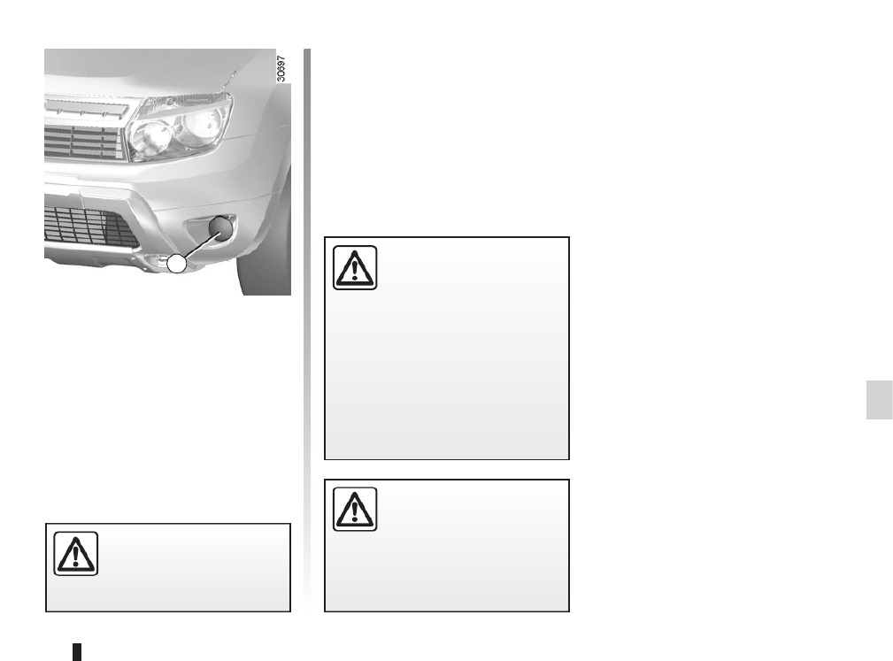
5.17
Additional lights
If you wish to fit fog lights or long range
headlights to your vehicle, consult an
approved dealer.
FOG LIGHTS: changing bulbs
Front fog lights 1
Consult an approved dealer.
Bulb type: H11.
Any operation on (or modi-
fication to) the electrical
system must be performed
by an approved Dealer
since an incorrect connection might
damage the electrical equipment
(harness, components and in partic-
ular the alternator). In addition, your
Dealer has all the parts required for
fitting these units.
The engine may be hot
during operations in close
proximity. In addition, the
engine cooling fan may
come on at any moment.
Risk of injury.
The bulbs are under pres-
sure and can break when
replaced.
Risk of injury.
1

5.18
7 Reversing light
Pear-shaped, bayonet type bulb, P
21 W.
or
Rear fog light
Pear-shaped, bayonet type P 21 W
bulb.
Refitting
To refit, proceed in the reverse order,
taking care not to damage the wiring.
REAR LIGHTS: changing bulbs (1/3)
Rear lights
Open the tailgate and undo nuts , then 1
release light unit by pulling it rear-2
wards.
Release clips to remove bulb holder .3 4
5 Side light and brake light
Pear-shaped, bayonet type bulb with
two P 21/5 W filaments.
6 Direction indicator light
Pear-shaped, bayonet type P 21 W
or PY 21 W bulb (depending on ve-
hicle). The bulbs are under pres-
sure and can break when
replaced.
Risk of injury.
1
2
3
3
4
5
6
7

5.19
REAR LIGHTS: changing bulbs (2/3)
The bulbs are under pres-
sure and can break when
replaced.
Risk of injury.
High-level brake light
The bulb for high-level brake light 9
may be accessed through the luggage
compartment.
Carefully unclip cover by pressing 8
tabs . 10
Remove bulb .13
Bulb type: P 21 W .
Unclip tab carefully (movement ) 12 A
and turn it an eighth of a turn (move-
ment ) to release the bulb holder B 11.
10
8
9
11
A
B12 13

5.20
REAR LIGHTS: changing bulbs (3/3)
Number plate light
Unclip light by pressing tab 14 15 using
a flat-blade screwdriver or similar.
Unclip lens and take out bulb .17 16
Bulb type: W 5 W.
14
15
17
16

5.21
INDICATOR LIGHTS: changing bulbs
Unclip indicator light (using a flat-1
blade screwdriver or similar positioned
at to move the indicator light towards A
the outside of the vehicle).
Turn bulb holder a quarter of a turn 2
(movement ) and take out bulb B 3
(movement ).C
Bulb type: WY5W .
The bulbs are under pres-
sure and can break when
replaced.
Risk of injury.
A
1
B
2
3
C

5.22
INTERIOR LIGHTS: changing bulbs (1/3)
Courtesy light
Unclip lens using a flat-blade screw-1
driver or similar.
Remove the bulb concerned.
Bulb type : W5W. 2
The bulbs are under pres-
sure and can break when
replaced.
Risk of injury.
12

5.23
INTERIOR LIGHTS: changing bulbs (2/3)
Press tab to release lens and 4 6
access bulb .5
Bulb type: W5W.
Glove box light
(depending on the vehicle)
Unclip light using a flat-blade screw-3
driver or similar, by pressing on the tab
to move the light towards the inside of
the unit.
Disconnect the light.
4 5 6
The bulbs are under pres-
sure and can break when
replaced.
Risk of injury.
3

5.24
INTERIOR LIGHTS: changing bulbs (3/3)
Luggage compartment light
Unclip light using a flat-blade screw-7
driver or similar, by pressing on tab 6 to
move the light towards the inside of the
luggage compartment.
The bulbs are under pres-
sure and can break when
replaced.
Risk of injury.
Remove the bulb .10
Bulb type: W5W.
Press tab to release lens .9 8
6
7
8
9
10

5.25
Passenger compartment fuses
If any electrical component does not
work, check the condition of the fuses.
Unclip flap using notch to help you.A 1
Use the fuse allocation label on the
back of flap to identify the fuses.A
Check the fuse in question and , if necessary, replace it with a fuse of
the same rating.
If a fuse is fitted where the rating is too high, it may cause the electrical
circuit to overheat (risk of fire) in the event of an item of equipment using
an excessive amount of current.
To comply with current legislation, or
as a precaution, you can obtain an
emergency kit from your approved
Dealer containing a set of spare
bulbs and fuses.
FUSES (1/3)
Tweezers 2
Release the fuse using tweezers , lo-2
cated on the back of flap . To remove A
the fuse from the tweezers, slide it side-
ways.
It is not advisable to use the free fuse
locations.
Fuses in engine compartment B
Some functions are protected by fuses
located in the engine compartment
(unit ).B
However, because of their reduced
accessibility, we advise you to have
your fuses replaced by an approved
dealer.
1
A
B
2

5.26
FUSES (2/3)
Symbol Allocation
ḽElectric front windows
ZInterior lighting
eElectric door mirror
àHeating
àNot used
ÅAir bag
PRight-hand main beam
headlight
Allocation of fuses in the passenger compartment
(the presence of certain fuses DEPENDS ON THE VEHICLE EQUIPMENT LEVEL)
Symbol Allocation
nABS
îRadio
ßBrake lights
àAir conditioning
GFront fog lights
aInstrument panel
Injection
fWindscreen wiper
Symbol Allocation
]Central locking of doors
and tailgate
CRear screen de-icing
ÙNot used
ÌHorn
ôMain power supply
ñHeated seats
sHeated door mirrors

5.27
FUSES (3/3)
Allocation of fuses in the passenger compartment
(the presence of certain fuses DEPENDS ON THE VEHICLE EQUIPMENT LEVEL)
Symbol Allocation
QLeft-hand main beam
headlight
LLeft-hand dipped beam
headlight
TRight-hand dipped
beam headlight
VRight-hand side light
YLeft-hand side light
FRear fog light
ḼElectric rear windows
Symbol Allocation
qEngine immobiliser
ËReversing light and rear
screen wiper
uPower-assisted steering
iAutomatic gearbox
GAS fuel
ḻ4-wheel drive (4WD)
transmission

5.28
BATTERY: troubleshooting (1/2)
To avoid all risk of sparks:
– Ensure that any consumers (cour-
tesy lights, etc.) are switched off
before disconnecting or reconnect-
ing the battery;
– when charging, stop the charger
before connecting or disconnecting
the battery;
– to avoid creating a short circuit be-
tween the terminals, do not place
metal objects on the battery;
– always wait at least one minute after
the engine has been switched off
before disconnecting a battery;
– make sure that you reconnect the
battery terminals after refitting.
Handle the battery with care
as it contains sulphuric acid,
which must not come into
contact with eyes or skin. If
it does, wash the affected area with
plenty of cold water and consult a
doctor, if necessary.
Ensure that naked flames, red hot
objects and sparks do not come into
contact with the battery as there is a
risk of explosion.
The engine may be hot when car-
rying out operations in close prox-
imity. In addition, the engine cooling
fan can come on at any moment.
Risk of serious injury.
Special procedures may be
required to charge some
batteries. Contact your ap-
proved dealer.
Avoid all risk of sparks which may
cause an immediate explosion, and
charge the battery in a well-venti-
lated area.
Risk of serious injury.
Connecting a battery charger
The battery charger must be com-
patible with a battery with nominal
voltage of 12 volts.
Do not disconnect the battery when the
engine is running. Follow the instruc-
tions given by the manufacturer of
the battery charger you are using.
When many accessories are fitted to
the vehicle, have them connected to
the + after ignition feed.

5.29
BATTERY: troubleshooting (2/2)
Starting the vehicle using the
battery from another vehicle
If you have to use the battery from an-
other vehicle to start, obtain suitable
jump leads (with a large cross section)
from an approved dealer or, if you al-
ready have jump leads, ensure that
they are in perfect condition.
The two batteries must have an iden-
tical nominal voltage of 12 volts. The
battery supplying the current should
have a capacity (amp-hours, Ah) which
is at least the same as that of the dis-
charged battery.
Ensure that there is no risk of contact
between the two vehicles (risk of short
circuiting when the positive terminals
are connected) and that the discharged
battery is properly connected. Switch
off your vehicle ignition.
Start the engine of the vehicle supply-
ing the current and run it at an interme-
diate engine speed.
Connect the positive (+) lead to (+) A
terminal of the discharged battery, 1
then to (+) terminal of the battery sup-2
plying the current.
Connect the negative (–) lead to (–) B
terminal of the battery supplying the 3
current and then to (–) terminal of the 4
discharged battery.
Start the engine as normal. As soon as
it is running, disconnect leads and A B
in the reverse order (---)4321
Check that there is no con-
tact between leads and A B
and that the positive lead A
is not touching any metal
parts on the vehicle supplying the
current.
Risk of injury and/or damage to the
vehicle.
AB
14
23

5.32
TOWING: breakdown (1/3)
Towing procedure
The steering wheel must be un-
locked and the ignition key must be
in position M (ignition on) to pro-
vide stop lights and hazard warning
lights on the towed vehicle. At night
the vehicle must have its lights on.
Unhitch the trailer, etc., if one is being
towed.
You must observe the towing regu-
lations which apply in the country in
which you are driving: do not exceed
the towing weight for your vehicle.
Contact an approved Dealer.
Front and rear towing points
Only use the front and rear 1 2
towing points.
When the engine is
stopped, steering and brak-
ing assistance are not op-
erational.
Do not leave the tools unse-
cured inside the vehicle as
they may come loose under
braking.
– Use a rigid towing bar (except for off-road recovery). If a rope or cable
is used (where the law allows this), the vehicle being towed must be able
to brake.
– A vehicle must not be towed if it is not fit to be driven.
– Avoid accelerating or braking suddenly when towing, as this may result in
damage being caused to the vehicle.
– When towing a vehicle, it is advisable not to exceed .15 mph (25 km/h)
These towing points may only be used
for towing: never use them for lifting the
vehicle directly or indirectly.
1
2

5.33
TOWING: breakdown (2/3)
4-wheel drive vehicles (4WD)
Whichever type of gearbox is fitted, a
4WD vehicle must never be towed if
any of its 4 wheels are touching the
ground.
Off-road recovery
If your vehicle is stuck in sand, snow
or mud, attach a flexible towing device
(towing belt or other device specially
designed for this purpose) to the front
or rear towing point (refer to the in-
formation on “Front and rear towing
points” on the previous page).
For off-road recovery, it
is forbidden to use a rigid
bar to tow a vehicle that is
stuck. Risk of mechanical
damage.
You must never tow a 4-wheel drive
vehicle, irrespective of the mode se-
lected, if one of the 4 wheels is in
contact with the ground (except for
off-road recovery). Risk of mechani-
cal damage.
Refer to the manufacturer’s instruc-
tions for information on how to fit
and operate the equipment.
If a ( ) vehicle becomes 4x4 4WD
stuck, it should only be towed for a
short distance. Risk of mechanical
damage.

5.34
TOWING: breakdown (3/3)
If the lever is stuck in , P
even though you are de-
pressing the brake pedal,
the lever can be released
manually.
To do this, unclip the cover at the
base of the lever.
Simultaneously press button and 3
unlocking button .4
When storing the tools,
ensure they are securely re-
placed in the luggage com-
partment, in their original
position.
Do not leave the tools unsecured
inside the vehicle as they may come
loose under braking.
3
4
Vehicle equipped with an automatic
gearbox

5.35
TOWING: towing equipment
A
Permissible nose weight, maxi-
mum permissible towing weight
braked and unbraked:
Refer to the information on “Weights”
in Section 6.
Refer to the manufacturer’s instruc-
tions for information on how to fit
and operate the towing equipment.
Please keep these instructions with
the rest of the vehicle documenta-
tion.
A = 893 mm.

5.36
FITTED AUDIO EQUIPMENT (1/2)
Radio location 1
If your vehicle is not fitted with an audio
system, one can be fitted and locations
have been provided for:
– the radio ;1
– front speakers ;2
– rear speakers .3
To install any equipment, please con-
sult an approved dealer.
Unclip and remove storage compart-
ment . 1
– In all cases, it is very important to follow the manufacturer’s instructions care-
fully.
– The specifications of the brackets and wires (available from our network) vary
depending on the equipment level of your vehicle and the type of radio.
Consult an approved dealer to find out the correct part number.
– No work may be carried out on the vehicle’s electrical or radio circuits, except
by approved Dealers: an incorrectly connected system may result in damage
being caused to the electrical equipment and/or the components connected to
it.
11

5.37
FITTED AUDIO EQUIPMENT (2/2)
Location for front speaker 2
Unclip cover using a flat-blade screw-2
driver or similar.
Location for rear speaker 3
Unclip cover using a flat-blade screw-3
driver or similar.
2
3

5.39
OPERATING FAULTS (1/5)
The following advice will enable you to carry out quick, temporary repairs. For safety reasons you should always contact
an approved dealer as soon as possible.
The starter is activated POSSIBLE CAUSES WHAT TO DO
Warning lights dim or fail to come on;
the starter does not run.
Battery terminals disconnected,
oxidised or incorrectly secured.
Retighten them, reconnect them or clean
them if they are oxidised.
Battery discharged or worn. Connect another battery to the faulty bat-
tery. Refer to the information on “Battery:
troubleshooting” in Section 5 or replace the
battery if necessary.
Do not push the vehicle if the steering
column is locked.
The engine will not start. Starting conditions are not fulfilled. Refer to the information on “Starting/stop-
ping the engine in Section 2.
The steering column remains locked. Steering wheel locked. To unlock, gently move the key and the
steering wheel (refer to the information on
the “Ignition switch” in Section 2).

5.43
OPERATING FAULTS (5/5)
Electrical equipment POSSIBLE CAUSES WHAT TO DO
The wipers do not work. Wiper blades stuck. Free the blades before using the wipers.
Faulty electrical circuit. Consult an approved dealer.
The wiper does not stop. Faulty electrical controls. Consult an approved dealer.
Direction indicators flashing more
quickly.
Blown bulb. Replace the bulb.
The direction indicators do not work. Faulty electrical circuit. Consult an approved dealer.
The headlights do not switch on or off. Faulty electrical circuit or control. Consult an approved dealer
Traces of condensation in the lights. This is not a fault. Traces of condensa-
tion are a natural phenomenon caused
by variations in temperature.
These traces soon disappear when the
lights are switched on.

5.44

6.1
Section 6: Technical specifications
Vehicle identification plate . . . . . . . . . . . . . . . . . . . . . . . . . . . . . . . . . . . . . . . . . . . . . . . . . . . . . . . . . 6.2
Engine specifications . . . . . . . . . . . . . . . . . . . . . . . . . . . . . . . . . . . . . . . . . . . . . . . . . . . . . . . . . . . . . 6.5
Weights/Towing weights . . . . . . . . . . . . . . . . . . . . . . . . . . . . . . . . . . . . . . . . . . . . . . . . . . . . . . . . . . 6.6
Replacement parts and repairs . . . . . . . . . . . . . . . . . . . . . . . . . . . . . . . . . . . . . . . . . . . . . . . . . . . . . 6.7
Service sheets . . . . . . . . . . . . . . . . . . . . . . . . . . . . . . . . . . . . . . . . . . . . . . . . . . . . . . . . . . . . . . . . . . 6.8
Anti-corrosion check . . . . . . . . . . . . . . . . . . . . . . . . . . . . . . . . . . . . . . . . . . . . . . . . . . . . . . . . . . . . . 6.14

6.2
Quote the details given on identifica-
tion plate on all letters or orders.A
VEHICLE IDENTIFICATION PLATE
Vehicle identification plate A
Vehicle type and chassis number.1
MMAC (Maximum permissible 2
all-up weight).
MTR (Total train weight – vehicle 3
fully loaded, with trailer).
MMTA (Maximum permissible 4
weight) front axle.
Maximum permissible weight on 5
rear axle.
Technical specifications of vehicle.6
Vehicle paint reference.7
Equipment level.8
Vehicle type.9
10 Trim code.
11 Additional equipment specifica-
tion.
12 Fabrication number.
13 Interior trim code.
A
xx
1
2
3
4
5
A 6
7
8
9
10
11
12
13
x
XXXXX

6.3
ENGINE IDENTIFICATION PLATES
Quote the details given on identifica-
tion plate on all letters or orders.B
(Location varies depending on engine)
Engine type1
Engine suffix2
Engine number3
B B
B
B
1 2
3

6.4
DIMENSIONS (in metres)
(*) Unladen
0.822 2.673 0.820
4.315
1.560
1.567
1.822
1.690 * 1.634 *

6.5
ENGINE SPECIFICATIONS
Versions 1.6 16V 2.0 16V 1.5 dCi
Engine type
(see engine plate)
K4M F4R K9K
Cubic capacity (cc) 1,598 1998 1,461
Type of fuel
Octane rating
Petrol
It is essential to use unleaded petrol and this must
be of the octane rating stated on the label inside the
fuel filler flap.
If not available, for a limited time only, use unleaded
fuel:
– with an octane rating of 91 for a label with the rat-
ings 95 or 98;
– with an octane rating of 87 for a label showing 91,
95 or 98.
Diesel
The label located in the fuel filler
flap indicates the authorised fuels.
Spark plugs Only use the spark plugs specified for your vehicle’s engine.
The type should be marked on a label affixed inside the engine compartment. If it is not
then contact an authorised dealer.
Fitting spark plugs which are not to specification may damage the engine.
Produktspezifikationen
| Marke: | Renault |
| Kategorie: | Auto |
| Modell: | Duster (2009) |
Brauchst du Hilfe?
Wenn Sie Hilfe mit Renault Duster (2009) benötigen, stellen Sie unten eine Frage und andere Benutzer werden Ihnen antworten
Bedienungsanleitung Auto Renault

30 August 2024
26 August 2024
11 August 2024
1 August 2024
1 August 2024
31 Juli 2024
30 Juli 2024
30 Juli 2024
29 Juli 2024
28 Juli 2024
Bedienungsanleitung Auto
- Auto Mitsubishi
- Auto Cadillac
- Auto Pioneer
- Auto Hyundai
- Auto Tesla
- Auto Citroën
- Auto Skoda
- Auto Chevrolet
- Auto Jaguar
- Auto Peugeot
- Auto Mercedes-Benz
- Auto Acme
- Auto BMW
- Auto Honda
- Auto Infiniti
- Auto Audi
- Auto Jeep
- Auto Smart
- Auto Ford
- Auto Lexus
- Auto Volkswagen
- Auto Volvo
- Auto Toyota
- Auto Genesis
- Auto Kia
- Auto Porsche
- Auto Opel
- Auto Nissan
- Auto Suzuki
- Auto Seat
- Auto Subaru
- Auto RAM
- Auto Mini
- Auto Land Rover
- Auto Mazda
- Auto Dacia
- Auto Vauxhall
- Auto Buick
- Auto Fiat
- Auto Alfa Romeo
- Auto MG
- Auto Saturn
- Auto Dodge
- Auto DS
- Auto Lancia
- Auto Maserati
- Auto Mercury
- Auto POLARIS
- Auto Polestar
- Auto Saab
- Auto Sharper Image
- Auto GEM
- Auto Chrysler
- Auto Pontiac
- Auto Lincoln
- Auto Rover
- Auto Tata
- Auto Acura
- Auto GMC
- Auto Mahindra
- Auto Scion
- Auto Lada
- Auto VDL
- Auto Abarth
- Auto Chery
Neueste Bedienungsanleitung für -Kategorien-

3 Dezember 2024

30 November 2024
30 November 2024

16 Oktober 2024

16 Oktober 2024

16 Oktober 2024

15 Oktober 2024

15 Oktober 2024

15 Oktober 2024
15 Oktober 2024