NEC NP405 Bedienungsanleitung
Lesen Sie kostenlos die 📖 deutsche Bedienungsanleitung für NEC NP405 (114 Seiten) in der Kategorie Beamer. Dieser Bedienungsanleitung war für 11 Personen hilfreich und wurde von 2 Benutzern mit durchschnittlich 4.5 Sternen bewertet
Seite 1/114
Portable Projector
NP610/NP510/NP410/NP405/
NP310/NP305/NP510W/NP410W
NP610S/NP510WS
User’s Manual
The projector’s model name indicated on the projector’s label is NP610,
NP510, NP410, NP405, NP310, NP305, NP510W, NP410W, NP610S,
NP510WS, NP610G, NP510G, NP410G, NP405G, NP310G, NP305G,
NP510WG, NP410WG, NP610SG, and NP510WSG respectively.
All the models are referred to as NP610, NP510, NP410, NP405,
NP310, NP305, NP510W, NP410W, NP610S, and NP510WS through-
out the user’s manual except some of the specification pages.
The NP405 and NP305 are not distributed in North America.
NP610/NP510/NP410/NP405/NP310/NP305/NP510W/NP410W
NP610S/NP510WS

1st edition, July 2009
• IBMisatrademarkorregisteredtrademarkofInternationalBusinessMachinesCorporation.
• Macintosh,MacOSXandPowerBookaretrademarksofAppleInc.registeredintheU.S.andothercountries.
• Microsoft,Windows,WindowsVista,InternetExplorer,.NETFrameworkand PowerPoint areeitheraregistered
trademarkortrademarkofMicrosoftCorporationintheUnitedStatesand/orothercountries.
• MicroSaverisaregisteredtrademarkofKensingtonComputerProductsGroup,adivisionofACCOBrands.
• VirtualRemoteToolusesWinI2C/DDClibrary,©NicomsoftLtd.
• Otherproductandcompanynamesmentionedinthisuser’smanualmaybethetrademarksorregisteredtrademarks
of their respective holders.
NOTES
(1)Thecontentsofthisuser’smanualmaynotbereprintedinpartorwholewithoutpermission.
(2)Thecontentsofthisuser’smanualaresubjecttochangewithoutnotice.
(3)Greatcarehasbeentakeninthepreparationofthisuser’smanual;however,shouldyounoticeanyquestionable
points, errors or omissions, please contact us.
(4)Notwithstandingarticle(3),NECwillnotberesponsibleforanyclaimsonlossofprotorothermattersdeemed
to result from using the Projector.

i
Important Information
Safety Cautions
Precautions
PleasereadthismanualcarefullybeforeusingyourNECNP610,NP510,NP410,NP405,NP310,NP305,NP510W,
NP410W,NP610S,andNP510WSprojectorandkeepthemanualhandyforfuturereference.
CAUTION
Toturnoffmainpower,besuretoremovetheplugfrompoweroutlet.
Thepoweroutletsocketshouldbeinstalledasneartotheequipmentaspossible,andshouldbeeasily
accessible.
CAUTION
TOPREVENTSHOCK,DONOTOPENTHECABINET.
THEREAREHIGH-VOLTAGECOMPONENTSINSIDE.
REFERSERVICINGTOQUALIFIEDSERVICEPERSONNEL.
Thissymbolwarnstheuserthatuninsulatedvoltagewithintheunitmaybesufcienttocauseelectrical
shock.Therefore,itisdangeroustomakeanykindofcontactwithanypartinsideoftheunit.
This symbol alerts the user that important information concerning the operation and maintenance of this
unit has been provided.
The information should be read carefully to avoid problems.
WARNING: TOPREVENTFIREORSHOCK,DONOTEXPOSETHISUNITTORAINORMOISTURE.
DONOTUSETHISUNIT’SPLUGWITHANEXTENSIONCORDORINANOUTLETUNLESSALLTHEPRONGS
CANBEFULLYINSERTED.
DOC Compliance Notice (for Canada only)
This Class B digital apparatus meets all requirements of the Canadian Interference-Causing Equipment Regula-
tions.
Machine Noise Information Regulation - 3. GPSGV,
Thehighestsoundpressurelevelislessthan70dB(A)inaccordancewithENISO7779.
CAUTION
Avoid displaying stationary images for a prolonged period of time.
DoingsocanresultintheseimagesbeingtemporarilysustainedonthesurfaceoftheLCDpanel.
Ifthisshouldhappen,continuetouseyourprojector.Thestaticbackgroundfrompreviousimageswill
disappear.
Disposing of your used product
EU-widelegislationasimplementedineachMemberStaterequiresthatusedelectricalandelectronic
productscarryingthemark(left)mustbedisposedofseparatelyfromnormalhouseholdwaste.Thisin-
cludes projectors and their electrical accessories or lamps. When you dispose of such products, please
followtheguidanceofyourlocalauthorityand/orasktheshopwhereyoupurchasedtheproduct.
Aftercollectingtheusedproducts,theyarereusedandrecycledinaproperway.Thiseffortwillhelpus
reducethewastesaswellasthenegativeimpactsuchasmercurycontainedinalamptothehuman
health and the environment at the minimum level.
ThemarkontheelectricalandelectronicproductsonlyappliestothecurrentEuropeanUnionMember
States.

ii
Important Information
WARNING TO CALIFORNIA RESIDENTS:
Handlingthecablessuppliedwiththisproductwillexposeyoutolead,achemicalknowntotheStateofCalifornia
to cause birth defects or other reproductive harm. WASH HANDS AFTER HANDLING.
RF Interference (for USA only)
WARNING
TheFederalCommunicationsCommissiondoesnotallowanymodicationsorchangestotheunitEXCEPTthose
speciedbyNECDisplaySolutionsofAmerica,Inc.inthismanual.Failuretocomplywiththisgovernmentregu-
lationcouldvoidyourrighttooperatethisequipment.Thisequipmenthasbeentestedandfoundtocomplywith
thelimitsforaClassBdigitaldevice,pursuanttoPart15oftheFCCRules.Theselimitsaredesignedtoprovide
reasonableprotectionagainstharmfulinterferenceinaresidentialinstallation.Thisequipmentgenerates,uses,and
canradiateradiofrequencyenergyand,ifnotinstalledandusedinaccordancewiththeinstructions,maycause
harmfulinterferencetoradiocommunications.However,thereisnoguaranteethatinterferencewillnotoccurina
particular installation.
Ifthisequipmentdoescauseharmfulinterferencetoradioortelevisionreception,whichcanbedeterminedby
turningtheequipmentoffandon,theuserisencouragedtotrytocorrecttheinterferencebyoneormoreofthe
followingmeasures:
•Reorientorrelocatethereceivingantenna.
•Increasetheseparationbetweentheequipmentandreceiver.
•Connecttheequipmentintoanoutletonacircuitdifferentfromthattowhichthereceiverisconnected.
•Consultthedealeroranexperiencedradio/TVtechnicianforhelp.
ForUKonly:InUK,aBSapprovedpowercablewithmouldedplughasaBlack(veAmps)fuseinstalledforusewith
thisequipment.Ifapowercableisnotsuppliedwiththisequipmentpleasecontactyoursupplier.
Important Safeguards
Thesesafetyinstructionsaretoensurethelonglifeofyourprojectorandtopreventreandshock.Pleasereadthem
carefullyandheedallwarnings.
Installation
•Donotplacetheprojectorinthefollowingconditions:
- on an unstable cart, stand, or table.
-nearwater,baths,ordamprooms.
- in direct sunlight, near heaters, or heat radiating appliances.
-inadusty,smokyorsteamyenvironment.
- on a sheet of paper or cloth, rugs or carpets.
•Ifyouwishtohavetheprojectorinstalledontheceiling:
-Donotattempttoinstalltheprojectoryourself.
-Theprojectormustbeinstalledbyqualiedtechniciansinordertoensureproperoperationandreducetherisk
of bodily injury.
-Inaddition,theceilingmustbestrongenoughtosupporttheprojectorandtheinstallationmustbeinaccordance
withanylocalbuildingcodes.
- Please consult your dealer for more information.

iii
Important Information
Fire and Shock Precautions
• Ensurethatthereissufcientventilationandthatventsareunobstructedtopreventthebuild-upofheatinsideyour
projector.Allowatleast4inches(10cm)ofspacebetweenyourprojectorandawall.
• Donottrytotouchtheventilationoutletontheleftfront(whenseenfromthefront)asitcanbecomeheatedwhile
the projector is turned on and immediately after the projector is turned off.
• Preventforeignobjectssuchaspaperclipsandbitsofpaperfromfallingintoyourprojector.Donotattempttoretrieve
anyobjectsthatmightfallintoyourprojector.Donotinsertanymetalobjectssuchasawireorscrewdriverintoyour
projector.Ifsomethingshouldfallintoyourprojector,disconnectitimmediatelyandhavetheobjectremovedbya
qualiedservicepersonnel.
• Donotplaceanyobjectsontopoftheprojector.
• Donottouchthepowerplugduringathunderstorm.Doingsocancauseelectricalshockorre.
• Theprojectorisdesignedtooperateonapowersupplyof100-240VAC50/60Hz(NP610/NP510/NP410/NP405/
NP310/NP305/NP510W/NP410W/NP610S/NP510WS) or 200-240V AC 50/60 Hz (NP610G/NP510G/NP410G/
NP405G/NP310G/NP305G/NP510WG/NP410WG/NP610SG/NP510WSG).Ensurethatyourpowersupplytsthis
requirementbeforeattemptingtouseyourprojector.
• Donotlookintothelenswhiletheprojectorison.Seriousdamagetoyoureyescouldresult.
• Keepanyitemssuchasmagnifyingglassoutofthelightpathoftheprojector.Thelightbeingprojectedfromthe
lensisextensive,thereforeanykindofabnormalobjectsthatcanredirectlightcomingoutofthelens,cancause
unpredictable outcome such as fire or injury to the eyes.
• Donotplaceanyobjects,whichareeasilyaffectedbyheat,infrontofaprojectorexhaustvent.
Doingsocouldleadtotheobjectmeltingorgettingyourhandsburnedfromtheheatthatisemittedfromtheex-
haust.
WARNING
•Donotcoverthelenswiththelenscaporequivalentwhiletheprojectorison.Doingsocanleadtomeltingof
the cap due to the heat emitted from the light output.
•Donotplaceanyobjects,whichareeasilyaffectedbyheat,infrontoftheprojectorlens.Doingsocouldlead
to the object melting from the heat that is emitted from the light output.
Place the projector in a horizontal position
Thetiltangleoftheprojectorshouldnotexceed10degrees,norshouldtheprojectorbeinstalledinanywayother
thanthedesktopandceilingmount,otherwiselamplifecoulddecreasedramatically.
10°

iv
Important Information
• Handlethepowercablecarefully.Adamagedorfrayedpowercablecancauseelectricshockorre.
- Donotuseanypowercablesthanthesuppliedone.
- Donotbendortugthepowercableexcessively.
- Donotplacethepowercableundertheprojector,oranyheavyobject.
- Donotcoverthepowercablewithothersoftmaterialssuchasrugs.
- Donotheatthepowercable.
- Donothandlethepowerplugwithwethands.
• Turnofftheprojector,unplugthepowercableandhavetheprojectorservicedbyaqualiedservicepersonnelunder
thefollowingconditions:
- Whenthepowercableorplugisdamagedorfrayed.
- Ifliquidhasbeenspilledintotheprojector,orifithasbeenexposedtorainorwater.
- Iftheprojectordoesnotoperatenormallywhenyoufollowtheinstructionsdescribedinthisuser’smanual.
- Iftheprojectorhasbeendroppedorthecabinethasbeendamaged.
- Iftheprojectorexhibitsadistinctchangeinperformance,indicatinganeedforservice.
• Disconnectthepowercableandanyothercablesbeforecarryingtheprojector.
• Turnofftheprojectorandunplugthepowercablebeforecleaningthecabinetorreplacingthelamp.
• Turnofftheprojectorandunplugthepowercableiftheprojectorisnottobeusedforanextendedperiodoftime.
• WhenusingaLANcable(onlymodelswiththeRJ-45LANport):
Forsafety,donotconnecttotheconnectorforperipheraldevicewiringthatmighthaveexcessivevoltage.
CAUTION
• Donotusethetilt-footforpurposesotherthanoriginallyintended.Misusessuchasgrippingthetilt-footorhang-
ingonthewallcancausedamagetotheprojector.
• Donotsendtheprojectorinthesoftcasebyparceldeliveryserviceorcargoshipment.Theprojectorinsidethe
soft case could be damaged.
• Select[HIGH]inFanmodeifyoucontinuetousetheprojectorforconsecutivedays.(Fromthemenu,select
[SETUP] [OPTIONS(1)] [FANMODE] [HIGH].)→ → →
• Donottrytotouchtheventilationoutletontheleftfront(whenseenfromthefront)asitcanbecomeheatedwhile
the projector is turned on and immediately after the projector is turned off.
• DonotturnofftheACpowerfor60secondsafterthelampisturnedonandwhilethePOWERindicatorisblink-
inggreen.Doingsocouldcauseprematurelampfailure.
Remote Control Precautions
• Handletheremotecontrolcarefully.
• Iftheremotecontrolgetswet,wipeitdryimmediately.
• Avoidexcessiveheatandhumidity.
• Donotheat,takeapart,orthrowbatteriesintore.
• Ifyouwillnotbeusingtheremotecontrolforalongtime,removethebatteries.
• Ensurethatyouhavethebatteries’polarity(+/−)alignedcorrectly.
• Donotusenewandoldbatteriestogether,orusedifferenttypesofbatteriestogether.
• Disposeofusedbatteriesaccordingtoyourlocalregulations.

v
Important Information
Note for US Residents
Thelampinthisproductcontainsmercury.PleasedisposeaccordingtoLocal,StateorFederalLaws.
Lamp Replacement
• Toreplacethelamp,followallinstructionsprovidedonpage84.
• Besuretoreplacethelampwhenthemessage[THE LAMP HAS REACHED THE END OF ITS USABLE LIFE.
PLEASE REPLACE THE LAMP.]appears.Ifyoucontinuetousethelampafterthelamphasreachedtheend
ofitsusablelife,thelampbulbmayshatter,andpiecesofglassmaybescatteredinthelampcase.Donottouch
them as the pieces of glass may cause injury.
Ifthishappens,contactyourdealerforlampreplacement.
A Lamp Characteristic
The projector has a high-pressure mercury lamp as a light source.
Alamphasacharacteristicthatitsbrightnessgraduallydecreaseswithage.Alsorepeatedlyturningthelampon
andoffwillincreasethepossibilityofitslowerbrightness.
CAUTION:
• DONOTTOUCHTHELAMPimmediatelyafterithasbeenused.Itwillbeextremelyhot.Turntheprojectoroff
andthendisconnectthepowercable.Allowatleastonehourforthelamptocoolbeforehandling.
• Whenremovingthelampfromaceiling-mountedprojector,makesurethatnooneisundertheprojector.Glass
fragments could fall if the lamp has been burned out.
About High Altitude mode
•
Set[FANMODE]to[HIGHALTITUDE]whenusingtheprojectorataltitudesapproximately5500feet/1600metersor
higher.
Usingtheprojectorataltitudesapproximately5500feet/1600metersorhigherwithoutsettingto[HIGHALTITUDE]
cancausetheprojectortooverheatandtheprotectorcouldshutdown.Ifthishappens,waitacoupleminutesand
turn on the projector.
• Usingtheprojectorataltitudeslessthanapproximately5500feet/1600metersandsettingto[HIGHALTITUDE]
cancausethelamptoovercool,causingtheimagetoicker.Switch[FANMODE]to[AUTO].
• Usingtheprojectorataltitudesapproximately5500feet/1600metersorhighercanshortenthelifeofopticalcom-
ponents such as the lamp.
About Copyright of original projected pictures:
Please note that using this projector for the purpose of commercial gain or the attraction of public attention in a venue
suchasacoffeeshoporhotelandemployingcompressionorexpansionofthescreenimagewiththefollowingfunc-
tionsmayraiseconcernabouttheinfringementofcopyrightswhichareprotectedbycopyrightlaw.
[ASPECTRATIO],[KEYSTONE],Magnifyingfeatureandothersimilarfeatures.

vi
Table of Contents
Important Information ............................................................................................i
1. Introduction .......................................................................................................... 1
1What’sintheBox? ......................................................................................................... 1
IntroductiontotheProjector .......................................................................................... 2
CongratulationsonYourPurchaseoftheProjector ................................................. 2
Featuresyou’llenjoy: ............................................................................................... 2
About this user’s manual .......................................................................................... 3
Part Names of the Projector .......................................................................................... 5
Front/Top .................................................................................................................. 5
Rear ......................................................................................................................... 6
TopFeatures ............................................................................................................ 7
TerminalPanelFeatures .......................................................................................... 8
PartNamesoftheRemoteControl ............................................................................... 9
BatteryInstallation ................................................................................................. 10
RemoteControlPrecautions .................................................................................. 10
OperatingRangeforWirelessRemoteControl ...................................................... 10
2. Installation and Connections ................................................................... 11
1SettingUptheScreenandtheProjector ..................................................................... 11
SelectingaLocation............................................................................................... 11
ThrowDistanceandScreenSize ........................................................................... 15
MakingConnections .................................................................................................... 17
Enablingthecomputer’sexternaldisplay ............................................................... 17
ConnectingYourPCorMacintoshComputer ......................................................... 17
WhenViewingaDVIDigitalSignal(exceptNP405andNP305) ............................ 19
UsingTwoAnalogCOMPUTERInputsSimultaneously ......................................... 20
ConnectinganExternalMonitor ............................................................................ 21
ConnectingYourDVDPlayerwithComponentOutput ........................................... 22
ConnectingYourVCR............................................................................................. 23
ConnectingtoaNetwork(exceptNP405andNP305) ........................................... 24
ConnectingtheSuppliedPowerCable .................................................................. 25
3. Projecting an Image (Basic Operation) .............................................. 26
1 Turning on the Projector .............................................................................................. 26
NoteonStartupscreen(MenuLanguageSelectscreen) ...................................... 28
Selecting a Source ...................................................................................................... 29
Selecting the computer or video source................................................................. 29
AdjustingthePictureSizeandPosition ....................................................................... 30
AdjusttheTiltFoot ................................................................................................. 31
Zoom ...................................................................................................................... 32
Adjusting from the menu ........................................................................................ 32
Focus ..................................................................................................................... 33
CorrectingKeystoneDistortion .................................................................................... 34
CorrectingKeystoneDistortion .............................................................................. 34
Adjustingwithbuttonsonthecabinet .................................................................... 34
Adjusting from the menu ........................................................................................ 35
AdjustingwiththeAutoKeystoneFunction ............................................................ 36

vii
Table of Contents
OptimizingComputerSignalAutomatically ................................................................. 37
AdjustingtheImageUsingAutoAdjust .................................................................. 37
TurningUporDownVolume ........................................................................................ 37
7 Turning off the Projector .............................................................................................. 38
AfterUse...................................................................................................................... 39
4. Convenient Features ..................................................................................... 40
1TurningofftheImageandSound ................................................................................ 40
FreezingaPicture ....................................................................................................... 40
EnlargingaPicture ...................................................................................................... 40
ChangingEcoMode .................................................................................................... 41
CheckingEnergy-SavingEffect[CARBONMETER] ................................................... 42
PreventingtheUnauthorizedUseoftheProjector[SECURITY] ...................................... 43
7UsingtheOptionalRemoteMouseReceiver(NP01MR) ............................................ 46
NetworkSettingbyUsinganHTTPBrowser(exceptNP405andNP305) .................. 48
9UsingtheVGASignalCabletoOperatetheProjector(VirtualRemote) ..................... 51
5. Using On-Screen Menu ................................................................................ 56
1UsingtheMenus .......................................................................................................... 56
MenuElements ............................................................................................................ 57
ListofMenuItems ....................................................................................................... 58
MenuDescriptions&Functions[SOURCE] ................................................................ 60
MenuDescriptions&Functions[ADJUST] .................................................................. 61
MenuDescriptions&Functions[SETUP] .................................................................... 68
7MenuDescriptions&Functions[INFO.] ...................................................................... 78
MenuDescriptions&Functions[RESET] .................................................................... 80
6. Maintenance ...................................................................................................... 81
1CleaningorReplacingtheFilters ................................................................................ 81
CleaningtheCabinetandtheLens ............................................................................. 83
ReplacingtheLamp..................................................................................................... 84
7. Appendix ............................................................................................................... 87
1 Troubleshooting ........................................................................................................... 87
IndicatorMessages ................................................................................................ 87
Specifications .............................................................................................................. 90
CabinetDimensions .................................................................................................... 94
PinAssignmentsofD-SubCOMPUTERInputConnector .......................................... 96
MiniD-Sub15PinConnector ................................................................................ 96
CompatibleInputSignalList ........................................................................................ 97
PCControlCodesandCableConnection ................................................................... 98
PCControlCodes .................................................................................................. 98
CableConnection .................................................................................................. 98
PCControlConnector(D-SUB9P) ........................................................................ 98
7TroubleshootingCheckList .......................................................................................... 99
TravelCareGuide ....................................................................................................... 101

1
1
2
Projector
Lens cap
(24F44681) Soft case
(24BS7582)
1. Introduction
1 What’s in the Box?
Makesureyourboxcontainseverythinglisted.Ifanypiecesaremissing,contactyourdealer.
Pleasesavetheoriginalboxandpackingmaterialsifyoueverneedtoshipyourprojector.
Power cable
(US: 7N080235)
(EU: 7N080021)
VGA signal cable
(7N520073/7N520052)
NEC Projector CD-ROM
User’s manual (PDF) and
the utility software “Virtual
Remote Tool”
(7N951361)
For North America only
Registrationcard
Limitedwarranty
For customers in Europe:
YouwillndourcurrentvalidGuar-
anteePolicyonourWebSite:
www.nec-display-solutions.com
• ImportantInfomation(ForNorthAmerica:
7N8P9731) (For Other countries than North
America: 7N8P9731 and 7N8P9741)
• QuickSetupGuide(7N8P9721)
Remote control
(7N900901)
Batteries (AAA × 2)
DVI to VGA adapter (7N960234)
The NP405 and NP305 do not
come with the DVI to VGA adapter.
NP610/NP510/NP410/
NP405/NP310/NP305/
NP510W/NP410W
NP610S/NP510WS NP610/NP510/NP410/
NP310/NP510W/
NP410W
The NP405, NP305,
NP610S, and NP510WS
do not come with a soft
case.
Unlessotherwisedescribedintheuser’smanual,thedrawingsfortheprojectorcabinetshowexamplesoftheNP610.
Lens cap
(24FU0691)

2
1. Introduction
Introduction to the Projector
Thissectionintroducesyoutoyournewprojectoranddescribesthefeaturesandcontrols.
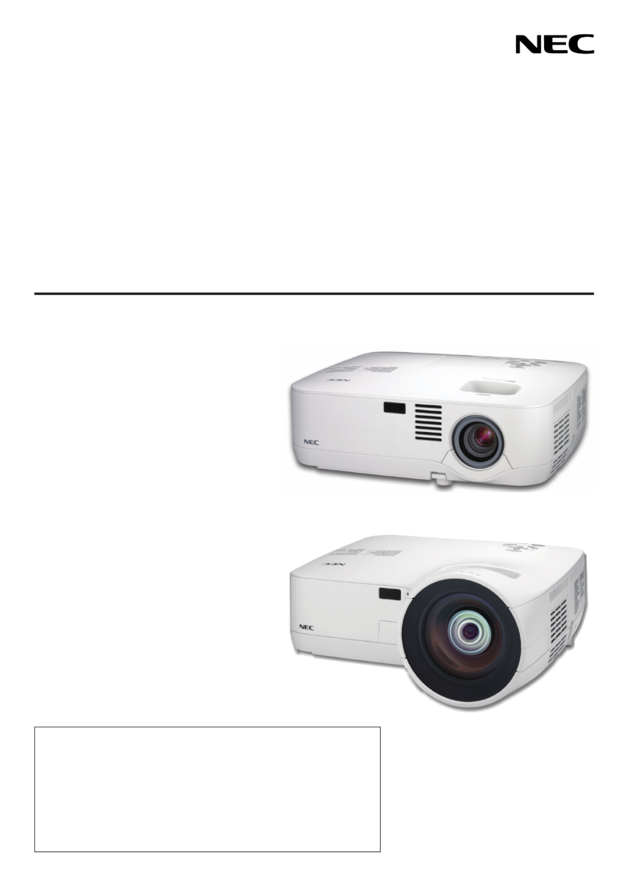
Congratulations on Your Purchase of the Projector
This projector is one of the very best projectors available today. The projector enables you to project precise images
upto300inches(110inchesonNP610S;104inchesonNP510WS)across(measureddiagonally)fromyourPCor
Macintoshcomputer(desktopornotebook),VCR,DVDplayer,ordocumentcamera.
Youcanusetheprojectoronatabletoporcart,youcanusetheprojectortoprojectimagesfrombehindthescreen,
and the projector can be permanently mounted on a ceiling* 1.Theremotecontrolcanbeusedwirelessly.
*1 Donotattempttomounttheprojectoronaceilingyourself.
Theprojectormustbeinstalledbyqualiedtechniciansinordertoensureproperoperationandreducetherisk
of bodily injury.
Inaddition,theceilingmustbestrongenoughtosupporttheprojectorandtheinstallationmustbeinaccordance
withanylocalbuildingcodes.Pleaseconsultyourdealerformoreinformation.
Features you’ll enjoy:
• Quickstart&QuickPowerOff
Lessthan4seconds*afterturningonthepower,theprojectorisreadytodisplayPCorvideoimages.
*Thequickstarttimeisonlywhen[STANDBYMODE]issetto[NORMAL]intheon-screenmessage.
Theprojectorcanbeputawayimmediatelyaftertheprojectorispowereddown.Nocooldownperiodisrequired
after the projector is turned off from the remote control or cabinet control panel.
• DirectPowerOff
Theprojectorhasafeaturecalled“DirectPowerOff”.Thisfeatureallowstheprojectortobeturnedoff(evenwhen
projectinganimage)byusingtheMainPowerSwitchordisconnectingtheACpowersupply.
ToturnofftheACpowersupplywhentheprojectorispoweredon,useapowerstripequippedwithaswitchand
abreaker.
• Lessthan1Winstandbyconditionwithenergysavingtechnology
Selecting[POWER-SAVING]for[STANDBYMODE]fromthemenucanputtheprojectorinpower-savingmode
thatconsumesonly0.6W(100-130VAC)/0.7W(200-240VAC).
• CarbonMeter
Thisfeaturewillshowenergy-savingeffectintermsofCO2emissionreduction(kg)whentheprojector’s[ECO
MODE]issetto[ON].
TheamountofCO2emissionreductionwillbedisplayedintheconrmationmessageatthetimeofpower-offand
intheINFOoftheon-screenmenu.
• 7Wbuilt-inspeakerforanintegratedaudiosolution
Powerful7wattspeakerprovidesvolumeneedforlargerooms.
• VirtualRemotefunction
TheVirtualRemotefunctionallowspowerOn/OffandsourceselectionoftheprojectorfromyourPCbyusingthe
suppliedVGAsignalcable.Theutilitysoftware“VirtualRemoteTool”exclusivelyfortheprojectorisrequiredtobe
installedfromtheaccompanyingNECProjectorCD-ROMontoyourcomputer.
AnaccompanyingNECProjectorCD-ROMincludestheutilitysoftware“VirtualRemoteTool”exclusivelyforthe
projectoranduser’smanualsinPDFformat.
• Shortthrowdistances(NP610S/NP510WS)
Shortfocallensesprovideforalargerimageusingashorterthrowdistancewhencomparedtoatypicalprojector
lens.

3
1. Introduction
• Avarietyofinputportsandacomprehensivearrayofsystemcontrolinterfaces
Thisprojectorsupportsinputsignalsonthefollowingports:DVI-Iconnector(DVI-I29Pin)withHDCPcompatible,
15pinD-Sub,compositeandS-video.
• AUTOPOWERONandAUTOPOWEROFFfeatures
TheAUTOPOWERON(AC),AUTOPOWERON(COMP1),AUTOPOWEROFF,andOFFTIMERfeatureseliminate
theneedtoalwaysusethePOWERbuttonontheremotecontrolorprojectorcabinet.
• Preventingunauthorizeduseoftheprojector
Enhancedsmartsecuritysettingsforkeywordprotection,cabinetcontrolpanellock,securityslot,andsecurity
chainopeningtohelppreventunauthorizedaccess,adjustmentsandtheftdeterrence.
• Theoptionalremotecontrol(NP02RC)allowsyoutoassignaCONTROLIDtotheprojector
Multipleprojectorscanbeoperatedseparatelyandindependentlywiththesamesingleremotecontrolbyassigning
anIDnumbertoeachprojector.
• IntegratedRJ-45connectorforwirednetworkingcapability(exceptNP405/NP305)
AnRJ-45connectorisequippedasstandardfeature.
• Autoverticalkeystonecorrection
AutoKeystonefeatureallowstheprojectortodetectitstiltandcorrectverticaldistortionautomatically.
• LCDprojectorwithhighresolutionandhighbrightness
Highresolutiondisplay-uptoUXGAcompatible,XGA(NP610/NP510/NP410/NP405/NP310/NP305/NP610S)/
WXGA(NP510W/NP410W/NP510WS)nativeresolution.
• Sixpicturepresetmodesforuseradjustablepictureandcolorsettings
Eachpicturepresetmodecanbecustomizedandmemorizedaccordingtoyourpreference.
• PCControlPort
YoucancontroltheprojectorwithaPCorcontrolsystemusingthePCControlport.
• Optionalremotemousereceiver
YoucanusethesuppliedwirelessremotecontrolandtheoptionalremotemousereceivertooperateyourPC
mousefromacrosstheroom.Theoptionalremotemousereceiver(NP01MR)supportsalmostanyPCusinga
USBconnection.
About this user’s manual
Thefastestwaytogetstartedistotakeyourtimeanddoeverythingrightthersttime.Takeafewminutesnowto
reviewtheuser’smanual.Thismaysaveyoutimelateron.Atthebeginningofeachsectionofthemanualyou’llnd
anoverview.Ifthesectiondoesn’tapply,youcanskipit.

4
1. Introduction
ComparativeTableofMainFeatures
Themainfeaturesvarydependingonthemodelasfollows.
StandardModels WidePanelModel Short-Throw
Model
WidePanel&
Short-Throw
Model
NP610 NP510 NP410 NP405 NP310 NP305 NP510W NP410W NP610S NP510WS
Native Aspect
Ratio
( page , )→90 92
Standard Wide Standard Wide
NativeResolution
(dots x lines*1)
( page , )→90 92
XGA(1024x768) WXGA
(1280 x 800)
XGA
(1024 x 768)
WXGA
(1280 x 800)
ScreenSize
( page , )→90 92 21"–300" 60"–110" 57"–104"
ThrowDistance
( page , )→90 92 30–444inches/0.7–11.3m 31–470inches/
0.8–11.9 m
35"–66"/
0.9 m–1.7 m
36"–66"/
0.9 m–1.7 m
Lightoutput*2*3
inOFFforECO
MODE
( page , )→90 92
3500
lumens
3000
lumens 2600 lumens 2200 lumens 3000
lumens
2600
lumens 2600 lumens 2100 lumens
WiredLAN
( page , )→24 48 RJ-45 RJ-45 RJ-45— —
Zoom
( page )→32 Usingthemanualzoomlever Usingthe[DIGITALZOOM]function
from the menu
Focus
( page )→33 Usingthemanualfocusring Usingthemanualfocuslever
LampReplace-
ment Time (aver-
age)
( page )→78
4000(H)inOFFforECOMODE/5000(H)inONforECOMODE
Forfurtherdetailsonthespecications,seepage90.
*1 Effectivepixelsaremorethan99.99%.
*2 Thisisthelightoutputvalue(lumens)whenthe[PRESET]modeissetto[HIGH-BRIGHT].Ifanyothermodeis
selectedasthe[PRESET]mode,thelightoutputvaluemaydropslightly.
*3 CompliancewithISO21118-2005
TIP: The model name is located on the cabinet.
Model name
MENU
EXIT
ENTER
STATUS
LAMP
AUTO ADJ.SO URCE
FOC US

5
1. Introduction
FO USC
Part Names of the Projector
Front/Top
NP610/NP510/NP410/NP405/NP310/NP305/NP510W/NP410W
Zoom Lever
( page )→32
Controls
( page )→7
Lens
Lens Cap
Built-in Security Slot ( )*
Focus Ring
( page )→33
Remote sensor
( page )→10
Ventilation (inlet) / Filter Cover
( page )→81
* ThissecurityslotsupportstheMicroSaver® Security System.
Adjustable Tilt Foot ( page )→31
Adjustable Tilt Foot Lever ( page )→31
Security chain opening
Attach an anti-theft device.
The security chain opening accepts se-
curity wires or chains up to 0.18 inch/
4.6 mm in diameter.
NP610S/NP510WS
FOCU S
Controls
( page )→7
Lens
Lens Cap
Built-in Security Slot ( )*
Focus Lever
( page )→33
Remote sensor
( page )→10
Ventilation (inlet) / Filter Cover
( page )→81
Adjustable Tilt Foot ( page )→31
Adjustable Tilt Foot Lever ( page )→31
Security chain opening
Attach an anti-theft device.
The security chain opening accepts se-
curity wires or chains up to 0.18 inch/
4.6 mm in diameter.
* ThissecurityslotsupportstheMicroSaver® Security System.

6
1. Introduction
AC Input
Connect the supplied power cable’s two-pin plug here, and
plug the other end into an active wall outlet. ( page )→25
Main Power Switch
When you plug the supplied power cable into an active wall outlet
and turn on the Main Power, the POWER indicator turns orange
and the projector is in standby mode.
( page , )→26 38
Terminal Panel ( page )→8
MonauralSpeaker(7W)
Ventilation (outlet)
Heated air is exhausted from here.
Ventilation (inlet) / Filter Cover
( page )→81
Lamp Cover ( page )→85
Rear Foot ( page )→31
Spacer(blackrubber)
To fine-adjust the height of the rear foot,
remove the spacer and rotate the rear
foot to the desired height.
Rear

7
1. Introduction
Top Features
STATUS
LAMP
AU ADJ.SOURCE TO
1 2 5 6
4
7
8
109
3
1. (POWER)Button( page , )→27 38
2. POWER Indicator ( page , , )→26 38 87
3. STATUS Indicator ( page )→87
4. LAMPIndicator( page , )→84 87
5. SOURCEButton( page )→29
6. AUTOADJ.Button( page )→37
7. MENUButton( page )→56
8. /VolumeButtons /KeystoneButtons
( page , )→34 37
9. ENTER Button ( page )→56
10.EXITButton( page )→56
8
1. Introduction
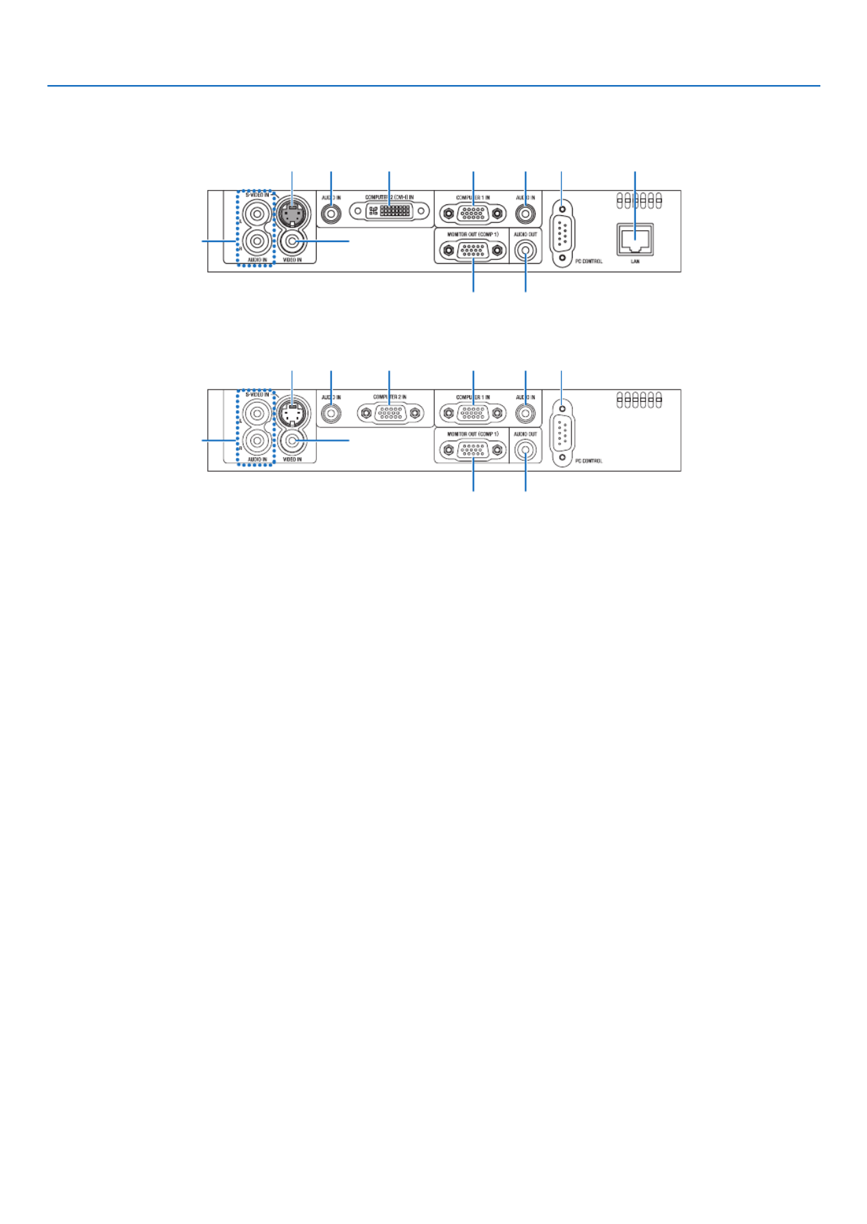
Terminal Panel Features
NP610/NP510/NP410/NP310/NP510W/NP410W/NP610S/NP510WS
6
8 7
3 32 1
5 4
9 10
NP405/NP305
6
8 7
3 32 1
5 4
9
1. COMPUTER1IN/ComponentInputConnector
(MiniD-Sub15Pin) ( page , , )→ 17 20 22
2. COMPUTER2(DVI-I)INConnector(29Pin)
(HDCPcompatible)( page , )→ 19 20
(NP610/NP510/NP410/NP310/NP510W/NP410W/
NP610S/NP510WS)
COMPUTER2IN/ComponentInputConnector
(MiniD-Sub15Pin)( page , , )→ 17 20 22
(NP405/NP305)
3. AUDIOINMiniJack(StereoMini)
( page , , )→ 17 19 22
4. AUDIOOUTMiniJack(StereoMini) ( page )→ 21
5. MONITOROUT(COMP1)Connector(MiniD-Sub
15Pin)( page )→ 21
6. S-VIDEOINConnector(MiniDIN4Pin)
(→ page )23
7. VIDEOINConnector(RCA) ( page )→ 23
8. AUDIOInputJacksL/R(RCA) ( page )→ 23
9. PCCONTROL[PCCONTROL]Port(D-Sub9Pin)
( page )→ 98
Use this port to connect a PC or control system.
This enables you to control the projector using serial
communicationprotocol.Ifyouarewritingyourown
program,typicalPCcontrolcodesareonpage98.
10.LANPort(RJ-45) ( page )→ 24
(notavailableonNP405/NP305)
9
1. Introduction
VOLUME
L-CLICK
ENTER
EXIT
MENU
UP
MAGNIFY GEPA
OFF
POWER
ON
AV-MUTE
DOWN
MOUSE
R-CLICK
COMPUTER
ASPECT HELP
FREEZEPICTURE
S-VIDEO
VIDEO
COMPUTER
AUTO ADJ.
ECO MODE
2
1
1
3
4
7
6
9
2
8
10
11
13
14
12
21
22
20
16
15
18
5
17
19
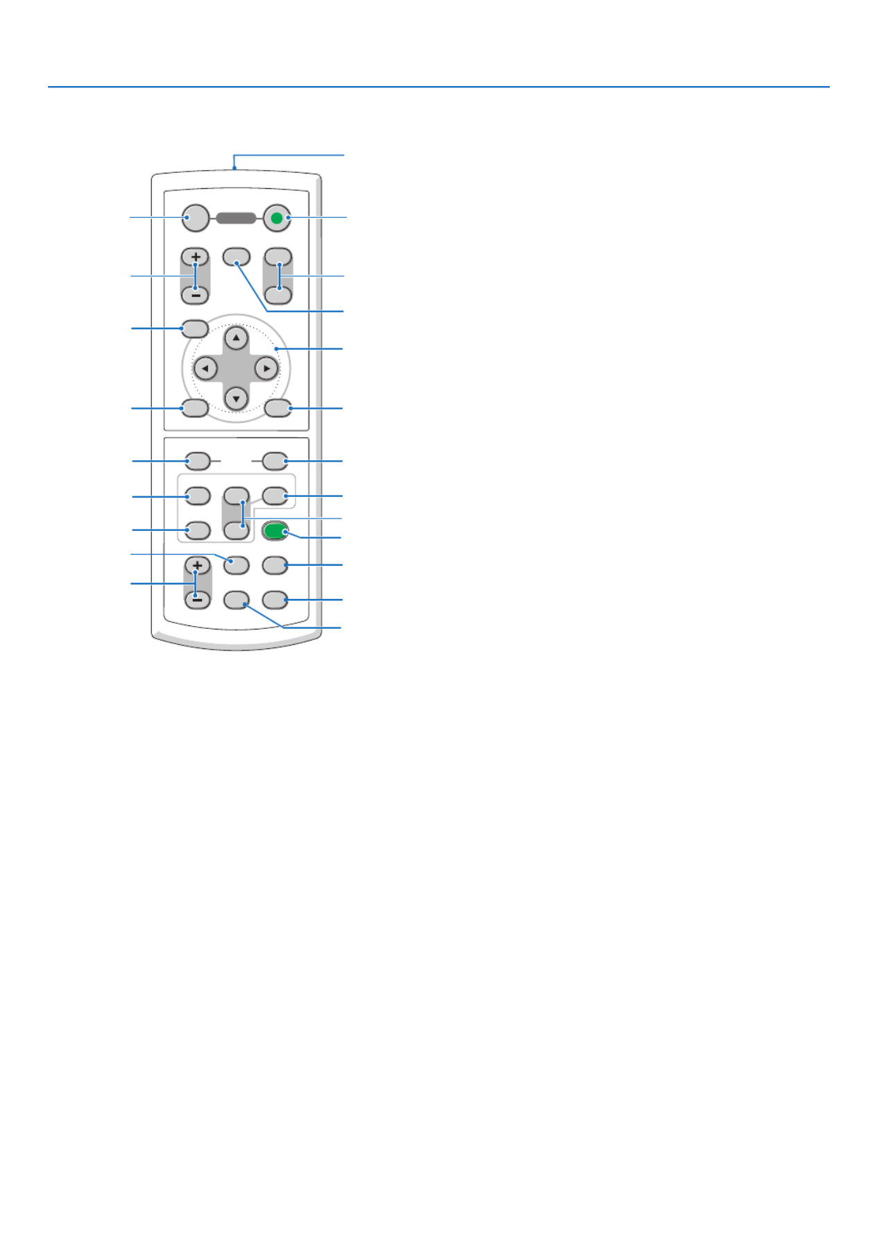
Part Names of the Remote Control
1. Infrared Transmitter
(→ page )10
2. POWER ON Button
(→ page )27
3. POWER OFF Button
(→ page )38
4. MAGNIFY(+)(−)Button
(→ page )40
5. AV-MUTEButton
(→ page )40
6. PAGEUP/DOWNButton*
(→ page , )46 47
7. MENUButton
(→ page )56
8. SELECT Button ( page )→ 56
9. ENTER Button ( page )→ 56
10.EXITButton( page )→ 56
11.MOUSEL-CLICKButton*
(→ page , )46 47
12.MOUSER-CLICKButton*
(→ page , )46 47
13.VIDEOButton
(→ page )29
14.S-VIDEOButton
(→ page )29
15.COMPUTER1/2Button
(→ page )29
16.AUTOADJ.Button
(→ page )37
17.VOLUME(+)(−)Button
(→ page )37
18. ECO MODE Button ( page )→ 41
19. ASPECT Button
(→ page )66
20.PICTUREButton
(→ page , )61 62
21. HELP Button
(→ page )78
22. FREEZE Button
(→ page )40
* ThePAGEUP/DOWN,MOUSEL-CLICKandMOUSER-CLICKbuttonsworkonlywhentheoptionalremotemouse
receiverisconnectedwithyourcomputer.

10
1. Introduction
Remote Control Precautions
• Handletheremotecontrolcarefully.
• Iftheremotecontrolgetswet,wipeitdryimmediately.
• Avoidexcessiveheatandhumidity.
• Donotheat,takeapart,orthrowbatteriesintore.
• Ifyouwillnotbeusingtheremotecontrolforalongtime,removethebatteries.
• Ensurethatyouhavethebatteries’polarity(+/−)alignedcorrectly.
• Donotusenewandoldbatteriestogether,orusedifferenttypesofbatteriestogether.
• Disposeofusedbatteriesaccordingtoyourlocalregulations.
Operating Range for Wireless Remote Control
1Press rmly and slide the battery
cover off.
2Installnewbatteries(AAA).Ensure
that you have the batteries’ polarity
(+/−)alignedcorrectly.
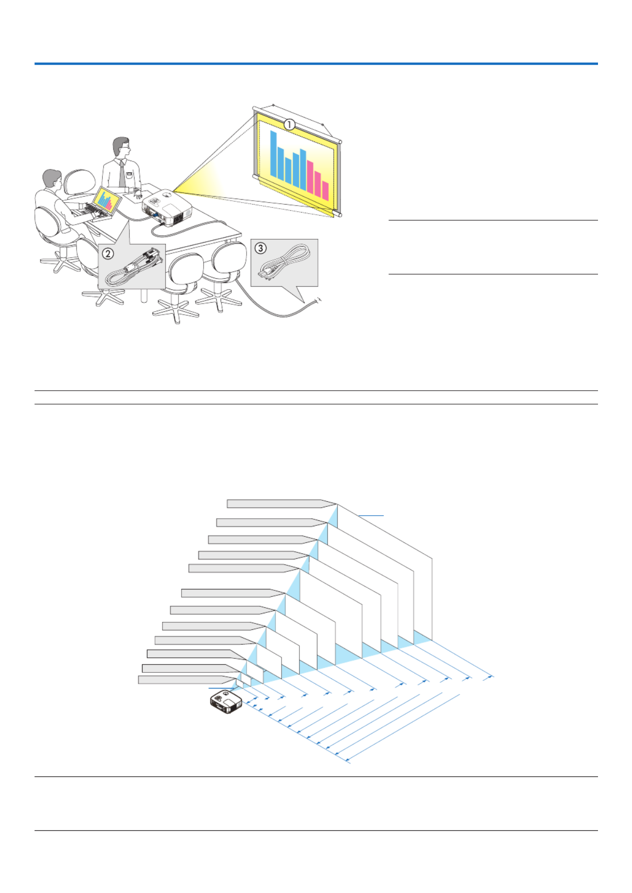
• Theinfraredsignaloperatesbyline-of-sightuptoadistanceofabout22feet/7mandwithina60-degreeangleof
the remote sensor on the projector cabinet.
• Theprojectorwillnotrespondifthereareobjectsbetweentheremotecontrolandthesensor,orifstronglightfalls
onthesensor.Weakbatterieswillalsopreventtheremotecontrolfromproperlyoperatingtheprojector.
Battery Installation
30°
30°
30°
30°
7 m/22 feet
7 m/22 feet
Remote control
Remote sensor on projector cabinet
3
Slipthe coverbackover thebat-
teriesuntilitsnapsintoplace.Do
not mix different types of batteries
ornewandoldbatteries.
Remote control
11
2. Installation and Connections
Thissectiondescribeshowtosetupyourprojectorandhowtoconnectvideoandaudiosources.
Yourprojectorissimpletosetupanduse.Butbeforeyougetstarted,youmustrst:
z Set up a screen and the projector.
x Connectyourcomputerorvideoequip-
ment to the projector.
(→ page , , , , , , )17 19 20 21 22 23 24
c Connect the supplied power cable.
( page )→ 25
NOTE: Ensure that the power cable and any other
cables are disconnected before moving the projec-
tor. When moving the projector or when it is not
in use, cover the lens with the lens cap.
1 Setting Up the Screen and the Projector
Selecting a Location
NOTE: Throw distances vary depending on the model.
[NP610/NP510/NP410/NP405/NP310/NP305]
Thefurtheryourprojectorisfromthescreenorwall,thelargertheimage.Theminimumsizetheimagecanbeis
approximately21"(0.53m)measureddiagonallywhentheprojectorisroughly30inches(0.8m)fromthewallor
screen.Thelargesttheimagecanbeis300"(7.6m)whentheprojectorisabout407inches(10.3m)fromthewall
or screen.
300"
240"
Distance
(Unit: m/inch)
Lens center
Screen Size
Screen Size (Unit: cm/inch)
200"
180"
150"
120"
100"
80"
10.3/407
"
8.3/325
"
6.2/244
"
5.1/203
"
4.1/162
"
3.4/135
"
2.7/107
"
2.0/81
"
1.3/53
"
40"
6.9/271
"
60"
30"
21"
1.0/
40
"
0.8/
30
"
609.6(W) 457.2(H) / 240(W) 180(H)� �
487.7(W) 365.8(H) / 192(W) 144(H)� �
406.4(W) 304.8(H) / 160(W) 120(H)� �
304.8(W) 228.6(H) / 120(W) 90(H)� �
365.8(W) 274.3(H) / 144(W) 108(H)� �
243.8(W) 182.9(H) / 96(W) 72(H)� �
203.2(W) 152.4(H) / 80(W) 60(H)� �
162.6(W) 121.9(H) / 64(W) 48(H)� �
121.9(W) 91.4(H) / 48(W) 36(H)� �
81.3(W) 61.0(H) / 32(W) 24(H)� �
61.0(W) 45.7(H) / 24(W) 18(H)� �
42.7(W) 32(H) / 17(W) 13(H)� �
TIP:
• Thedistancesareindicatedbyintermediatevaluesbetweenteleandwide.Useasaruleofthumb.
• TheZoomleveradjuststheimagesizebyupto+/−10%.
• Formoredetailsonthrowdistance,seepage15.
Tothewalloutlet.

12
2. Installation and Connections
[NP510W/NP410W]
Thefurtheryourprojectorisfromthescreenorwall,thelargertheimage.Theminimumsizetheimagecanbeis
approximately21"(0.53m)measureddiagonallywhentheprojectorisroughly31inches(0.8m)fromthewallor
screen.Thelargesttheimagecanbeis300"(7.6m)whentheprojectorisabout431inches(11.0m)fromthewall
or screen.
300"
240"
Distance
(Unit: m/inch)
Lens center
Screen Size
Screen Size (Unit: cm/inch)
200"
180"
150"
120"
100"
80"
11.0/431
"
8.8/345
"
6.6/258
"
5.5/215
"
4.4/172
"
3.6/143
"
2.9/114
"
2.2/85
"
1.4/56
"
40"
7.3/287
"
60"
30"
21"
0.9/
42
"
0.8/
31
"
646.2(W) 403.9(H) / 254(W) 159(H)� �
516.9(W) 323.1(H) / 204(W) 127(H)� �
430.8(W) 269.2(H) / 170(W) 106(H)� �
323.1(W) 201.9(H) / 127(W) 79(H)� �
387.7(W) 242.3(H) / 153(W) 95(H)� �
258.5(W) 161.5(H) / 102(W) 64(H)� �
215.4(W) 134.6(H) / 85(W) 53(H)� �
172.3(W) 107.7(H) / 68(W) 42(H)� �
129.2(W) 80.8(H) / 51(W) 32(H)� �
86.2(W) 53.8(H) / 34(W) 21(H)� �
64.6(W) 40.4(H) / 25(W) 16(H)� �
45.2(W) 28.3(H) / 18(W) 11(H)� �
TIP:
• Thedistancesareindicatedbyintermediatevaluesbetweenteleandwide.Useasaruleofthumb.
• TheZoomleveradjuststheimagesizebyupto+/−10%.
• Formoredetailsonthrowdistance,seepage15.

13
2. Installation and Connections
[NP610S]
Thefurtheryourprojectorisfromthescreenorwall,thelargertheimage.Theminimumsizetheimagecanbeisap-
proximately60"(1.52m)measureddiagonallywhentheprojectorisroughly35inches(0.9m)fromthewallorscreen.
Thelargesttheimagecanbeis110"(2.8m)whentheprojectorisabout66inches(1.7m)fromthewallorscreen.
110"
Distance
(Unit: m/inch)
Lens center
Screen Size
Screen Size (Unit: cm/inch)
223.5(W) 167.6(H)/88(W) 66(H) � �
203.2(W) 152.4(H)/80(W) 60(H)� �
182.9(W) 137.2(H)/72(W) 54(H)� �
162.6(W) 121.9(H)/64(W) 48(H)� �
156.5(W) 117.3(H)/62(W) 46(H)� �
142.2(W) 106.7(H)/56(W) 42(H)� �
130.0(W) 97.5(H)/51(W) 38(H)� �
121.9(W) 91.4(H)/48(W) 36(H)� �
100"
90"
80"
77"
70"
1.67/66"
1.51/59"
1.36/53"
1.20/47"
1.16/46"
1.05/41"
0.96/38"
0.90
/35"
60
"
64"
TIP:
• DigitalZoomcanresultinablurryimageduetotheelectroniczoom.
• TheDigitalZoomfunctionadjuststheimagesizebyupto−20%.(→ page 32)
• Formoredetailsonthrowdistance,seepage16.

14
2. Installation and Connections
[NP510WS]
Thefurtheryourprojectorisfromthescreenorwall,thelargertheimage.Theminimumsizetheimagecanbeisap-
proximately57"(1.45m)measureddiagonallywhentheprojectorisroughly36inches(0.9m)fromthewallorscreen.
Thelargesttheimagecanbeis104"(2.6m)whentheprojectorisabout66inches(1.7m)fromthewallorscreen.
104"
Distance
(Unit: m/inch)
Lens center
Screen Size
Screen Size (Unit: cm/inch)
224.0(W) 140.0(H)/88(W) 55(H)� �
215.4(W) 134.6(H)/85(W) 53(H)� �
193.9(W) 121.2(H)/76(W) 48(H)� �
187.4(W) 117.1(H)/74(W) 46(H)� �
172.3(W) 107.7(H)/68(W) 42(H)� �
150.8(W) 94.2(H)/59(W) 37(H)� �
129.2(W) 80.8(H)/51(W) 32(H)� �
122.8(W) 76.7(H)/48(W) 30(H)� �
100"
90"
87"
80"
70"
1.67/66"
1.60/63"
1.44/57"
1.39/55"
1.28/50"
1.11/44"
0.95/37"
0.90
/36"
57
"
60"
TIP:
• DigitalZoomcanresultinablurryimageduetotheelectroniczoom.
• TheDigitalZoomfunctionadjuststheimagesizebyupto−20%.(→ page 32)
• Formoredetailsonthrowdistance,seepage16.
15
2. Installation and Connections
C
α
B
D
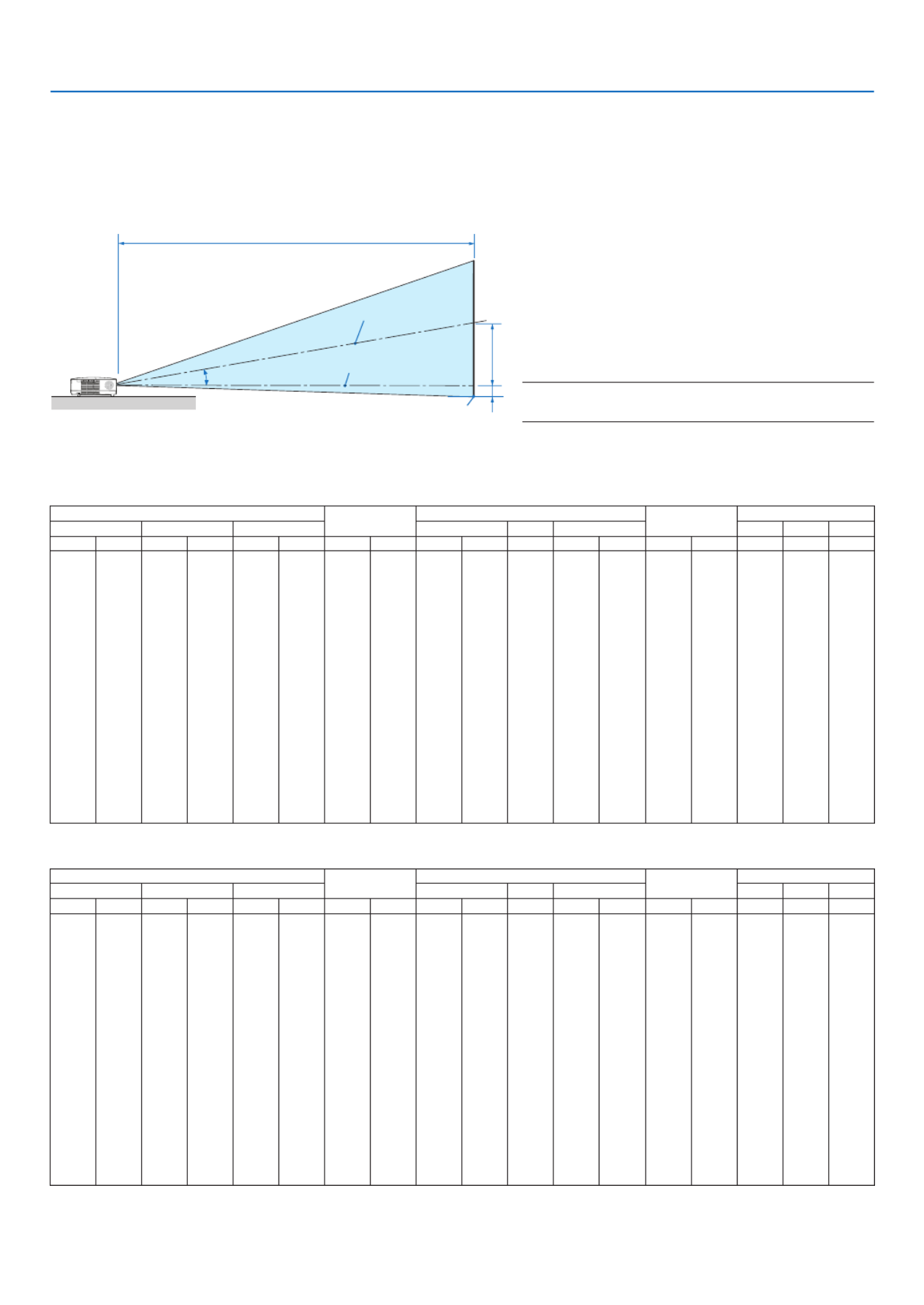
Throw Distance and Screen Size
Thefollowingshowstheproperrelativepositionsoftheprojectorandscreen.Refertothetabletodeterminethe
position of installation.
DistanceChart[NP610/NP510/NP410/NP405/NP310/NP305/NP510W/NP410W]
B= Vertical distance between lens center and
screen center
C= Throwdistance
D= Vertical distance between lens center and
screen bottom (top of screen for ceiling ap-
plication)
α= Throwangle
NOTE: The values in the tables are design values and
may vary.
[NP610/NP510/NP410/NP405/NP310/NP305]
Screen Size BCDα
Diagonal Width Height wide tele wide tele
inch mm inch mm inch mm inch mm inch mm - inch mm inch mm degree - degree
21 533 17 427 13 320 4 110 - - - 30 753 -2 -50 - - 8.3
25 635 20 508 15 381 5 131 29 746 - 36 903 -2 -60 10.0 - 8.3
30 762 24 610 18 457 6 157 36 903 - 43 1092 -3 -71 9.9 - 8.2
40 1016 32 813 24 610 8 210 48 1217 - 58 1469 -4 -95 9.8 - 8.1
60 1524 48 1219 36 914 12 314 73 1845 - 88 2223 -6 -143 9.7 - 8.0
72 1829 58 1463 43 1097 15 377 87 2221 - 105 2675 -7 -171 9.6 - 8.0
80 2032 64 1626 48 1219 17 419 97 2473 - 117 2977 -8 -191 9.6 - 8.0
84 2134 67 1707 50 1280 17 440 102 2598 - 123 3128 -8 -200 9.6 - 8.0
90 2286 72 1829 54 1372 19 471 110 2787 - 132 3354 -8 -214 9.6 - 8.0
100 2540 80 2032 60 1524 21 524 122 3101 - 147 3731 -9 -238 9.6 - 8.0
120 3048 96 2438 72 1829 25 629 147 3729 - 177 4485 -11 -286 9.6 - 8.0
150 3810 120 3048 90 2286 31 786 184 4671 - 221 5616 -14 -357 9.5 - 8.0
180 4572 144 3658 108 2743 37 943 221 5613 - 266 6747 -17 -429 9.5 - 8.0
200 5080 160 4064 120 3048 41 1048 246 6241 - 295 7501 -19 -476 9.5 - 8.0
210 5334 168 4267 126 3200 43 1100 258 6555 - 310 7878 -20 -500 9.5 - 7.9
240 6096 192 4877 144 3658 50 1257 295 7497 - 355 9009 -23 -572 9.5 - 7.9
270 6858 216 5486 162 4115 56 1414 332 8439 - 399 -25 -643 9.5 - 7.9 10140
300 7620 240 6096 180 4572 62 1572 369 9381 - 444 -28 -714 9.5 - 7.9 11271
[NP510W/NP410W]
Screen Size BCDα
Diagonal Width Height wide tele wide tele
inch mm inch mm inch mm inch mm inch mm - inch mm inch mm degree - degree
21 533 18 452 11 283 5 117 - - - 31 798 -1 -25 - - 8.3
25 635 21 538 13 337 5 139 31 791 - 38 957 -1 -29 10.0 - 8.3
30 762 25 646 16 404 7 167 38 957 - 46 1158 -1 -35 9.9 - 8.2
40 1016 34 862 21 538 9 222 51 1290 - 61 1557 -2 -47 9.8 - 8.1
60 1524 51 1292 32 808 13 333 77 1956 - 93 2356 -3 -71 9.7 - 8.0
72 1829 61 1551 38 969 16 400 93 2354 - 112 2835 -3 -85 9.6 - 8.0
80 2032 68 1723 42 1077 17 444 103 2621 - 124 3156 -4 -94 9.6 - 8.0
84 2134 71 1809 45 1131 18 466 108 2754 - 131 3316 -4 -99 9.6 - 8.0
90 2286 76 1939 48 1212 20 500 116 2954 - 140 3555 -4 -106 9.6 - 8.0
100 2540 85 2154 53 1346 22 555 129 3287 - 156 3955 -5 -118 9.6 - 8.0
120 3048 102 2585 64 1615 26 666 156 3953 - 187 4754 -6 -141 9.6 - 8.0
150 3810 127 3231 79 2019 33 833 195 4951 - 234 5953 -7 -177 9.5 - 8.0
180 4572 153 3877 95 2423 39 1000 234 5950 - 282 7152 -8 -212 9.5 - 8.0
200 5080 170 4308 106 2692 44 1111 260 6615 - 313 7951 -9 -236 9.5 - 8.0
210 5334 178 4523 111 2827 46 1166 274 6948 - 329 8351 -10 -247 9.5 - 7.9
240 6096 204 5169 127 3231 52 1333 313 7947 - 376 9550 -11 -283 9.5 - 7.9
270 6858 229 5816 143 3635 59 1499 352 8945 - 423 -13 -318 9.5 - 7.910748
300 7620 254 6462 159 4039 66 1666 391 9944 - 470 -14 -353 9.5 - 7.911947
Screen center
Lenscenter
Screen bottom
16
2. Installation and Connections
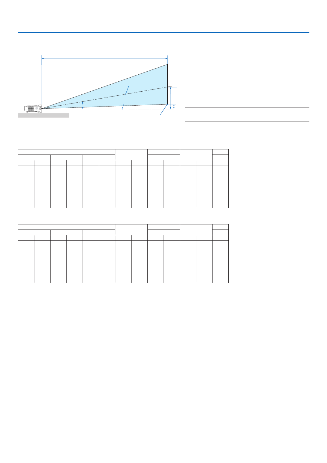
[NP610S]
Screen Size BCDα
Diagonal Width Height wide wide
inch mm inch mm inch mm inch mm inch mm inch mm degree
60 1524 48 1219 36 914 20 505 35 895 2 48 29.4
64 1626 51 1300 38 975 21 538 38 956 2 51 29.4
70 1778 56 1422 42 1067 23 589 41 1049 2 56 29.3
77 1956 62 1565 46 1173 26 648 46 1156 2 61 29.3
80 2032 64 1626 48 1219 27 673 47 1203 3 64 29.2
90 2286 72 1829 54 1372 30 757 53 1357 3 71 29.2
100 2540 80 2032 60 1524 33 841 59 1511 3 79 29.1
110 2794 88 2235 66 1676 36 926 66 1665 3 87 29.1
[NP510WS]
Screen Size BCDα
Diagonal Width Height wide wide
inch mm inch mm inch mm inch mm inch mm inch mm degree
57 1448 48 1228 30 767 20 508 36 902 5 125 29.4
60 1524 51 1292 32 808 21 535 37 951 5 131 29.4
70 1778 59 1508 37 942 25 624 44 1114 6 153 29.3
80 2032 68 1723 42 1077 28 713 50 1277 7 175 29.2
87 2210 74 1874 46 1171 31 776 55 1392 7 190 29.1
90 2286 76 1939 48 1212 32 803 57 1441 8 197 29.1
94 2388 80 2025 50 1265 33 838 59 1506 8 206 29.1
104 2642 88 2240 55 1400 37 928 66 1669 9 228 29.1
WARNING
* Installingyourprojectorontheceilingmustbedone
byaqualiedtechnician.ContactyourNECdealerfor
more information.
* Donotattempttoinstalltheprojectoryourself.
• Onlyuseyourprojectoronasolid,levelsurface.Ifthe
projector falls to the ground, you can be injured and
the projector severely damaged.
• Do not use the projector where temperatures vary
greatly. The projector must be used at temperatures
between41°F(5°C)and104°F(40°C)(Ecomodese-
lectedautomaticallyat95°Fto104°F/35°Cto40°C).
• Do not expose the projector to moisture, dust, or
smoke.Thiswillharmthescreenimage.
• Ensurethatyouhaveadequateventilationaroundyour
projectorsoheatcandissipate.Donotcoverthevents
on the side or the front of the projector.
ReectingtheImage
Usingamirrortoreectyourprojector’simageenables
youtoenjoyamuchlargerimagewhenasmallerspace
isrequired.ContactyourNECdealerifyouneedamirror
system.Ifyou’reusingamirrorsystemandyourimage
isinverted,usetheMENUand buttons on your
projector cabinet or your remote control to correct the
orientation. ( page )→ 72
C
α
B
D
B= Vertical distance between lens center and
screen center
C= Throwdistance
D= Vertical distance between lens center and
screen bottom (top of screen for ceiling ap-
plication)
α= Throwangle
NOTE: The values in the tables are design values and
may vary.
Screen center
Lenscenter
Screen bottom
DistanceChart[NP610S/NP510WS]

17
2. Installation and Connections
COMPUTER 1 INCOMPUTER 2 IN
AUDIO IN
PHONE
IBMVGAorCompatibles(Notebook
type)orMacintosh(Notebooktype)
VGA signal cable (supplied)
To mini D-Sub 15-pin connector on
the projector. It is recommended that
you use a commercially available
distribution amplier if connecting a
signal cable longer than the cable
supplied.
NOTE:ForolderMacintosh,useacommerciallyavailable
pinadapter(notsupplied)toconnecttoyourMac’svideo
port.
Audio cable
(not supplied)
Making Connections
NOTE: When using with a notebook PC, be sure to connect the projector and notebook PC while the projector is in standby mode
and before turning on the power to the notebook PC.
In most cases the output signal from the notebook PC is not turned on unless connected to the projector before being powered up.
* Ifthescreengoesblankwhileusingyourremotecontrol,itmaybetheresultofthecomputer’sscreen-saverorpowermanage-
ment software.
Enabling the computer’s external display
DisplayinganimageonthenotebookPC’sscreendoesnotnecessarilymeanitoutputsasignaltotheprojector.
WhenusingaPCcompatiblelaptop,acombinationoffunctionkeyswillenable/disabletheexternaldisplay.
Usually,thecombinationofthe“Fn”keyalongwithoneofthe12functionkeysgetstheexternaldisplaytocomeon
oroff.Forexample,NEClaptopsuseFn+F3,whileDelllaptopsuseFn+F8keycombinationstotogglethrough
external display selections.
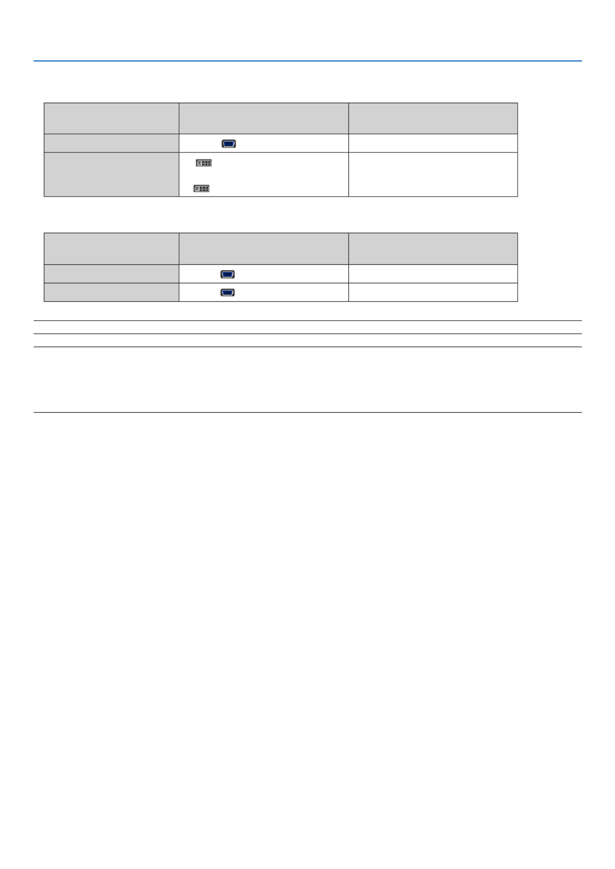
Connecting Your PC or Macintosh Computer
NOTE:SignalssupportedbyPlug&Play(DDC2)
Model
INPUT
COMPUTER 1 IN COMPUTER 2 IN
analog analog digital
NP610/NP510/NP410/NP310/
NP510W/NP410W/NP610S/NP510WS Yes Yes Yes
NP405/NP305 Yes Yes —
NP405/NP305
18
2. Installation and Connections
• Selectthesourcenameforitsappropriateinputconnectorafterturningontheprojector.
[NP610/NP510/NP410/NP310/NP510W/NP410W/NP610S/NP510WS]
Inputconnector SOURCEbuttonontheprojector
cabinet Buttonontheremotecontrol
COMPUTER1IN COMPUTER1 (COMPUTER1)
COMPUTER2(DVI-I)IN
COMPUTER2(DIGITAL)
or
COMPUTER2(ANALOG)
(COMPUTER2)
[NP405/NP305]
Inputconnector SOURCEbuttonontheprojector
cabinet Buttonontheremotecontrol
COMPUTER1IN COMPUTER1 (COMPUTER1)
COMPUTER2IN COMPUTER2 (COMPUTER2)
NOTE:TheprojectorisnotcompatiblewithvideodecodedoutputsoftheNECISS-6020switcher.
NOTE: An image may not be displayed correctly when a Video or S-Video source is played back via a commercially available scan
converter.
This is because the projector will process a video signal as a computer signal at the default setting. In that case, do the following.
* When an image is displayed with the lower and upper black portion of the screen or a dark image is not displayed correctly:
ProjectanimagetollthescreenandthenpresstheAUTOADJ.buttonontheremotecontrolortheprojectorcabinet.

19
2. Installation and Connections
When Viewing a DVI Digital Signal (except NP405 and NP305)
ToprojectaDVIdigitalsignal,besuretoconnectthePCandtheprojectorusingaDVIcable(notsupplied)before
turningonyourPCorprojector.TurnontheprojectorrstandselectComputer2(Digital)fromthesourcemenubefore
turningonyourPC.
Failuretodosomaynotactivatethedigitaloutputofthegraphicscardresultinginnopicturebeingdisplayed.Should
thishappen,restartyourPC.
DonotdisconnecttheDVIcablewhiletheprojectorisrunning.Ifthesignalcablehasbeendisconnectedandthen
re-connected,animagemaynotbecorrectlydisplayed.Shouldthishappen,restartyourPC.
NOTE:
• UseaDVIcableortheonecompliantwiththeDDWG(DigitalDisplayWorkingGroup)DVI(DigitalVisualInterface)revisio
standard.TheDVIcableshouldbewithin5m(196")long.BothsingleanddualtypesofDVIcablecanbeused.
• TheDVI(DIGITAL)connectoracceptsVGA(640x480),SVGA(800x600),1152x864,XGA(1024x768),WXGA(1280
@upto60Hz),andSXGA(1280x1024@upto60Hz).
COMPUTER 2 (DVI-I) IN
PHONE
AUDIO IN
Audio cable (not supplied)
IBMPCorCompatibles(Desktoptype)
orMacintosh(Desktoptype)
DVI cable (not supplied)
20
2. Installation and Connections
COMPUTER 1 IN
COMPUTER 2 (DVI-I) IN
COMPUTER 2 IN
AUDIO IN
PHONE
VGA signal cable
(supplied)
IBMPCorCompatibles(Notebooktype)
orMacintosh(Notebooktype)
IBMPCorCompatibles(Desktop
type)orMacintosh(Desktoptype)
VGA signal cable (not
supplied)
DVI to VGA adapter
(supplied)
NOTE:WhentheDVItoVGAadapterisnottobeusedforanextendedperiodoftime,removeitfromtheprojector.Failuretod
may cause damage to the connector of the projector.
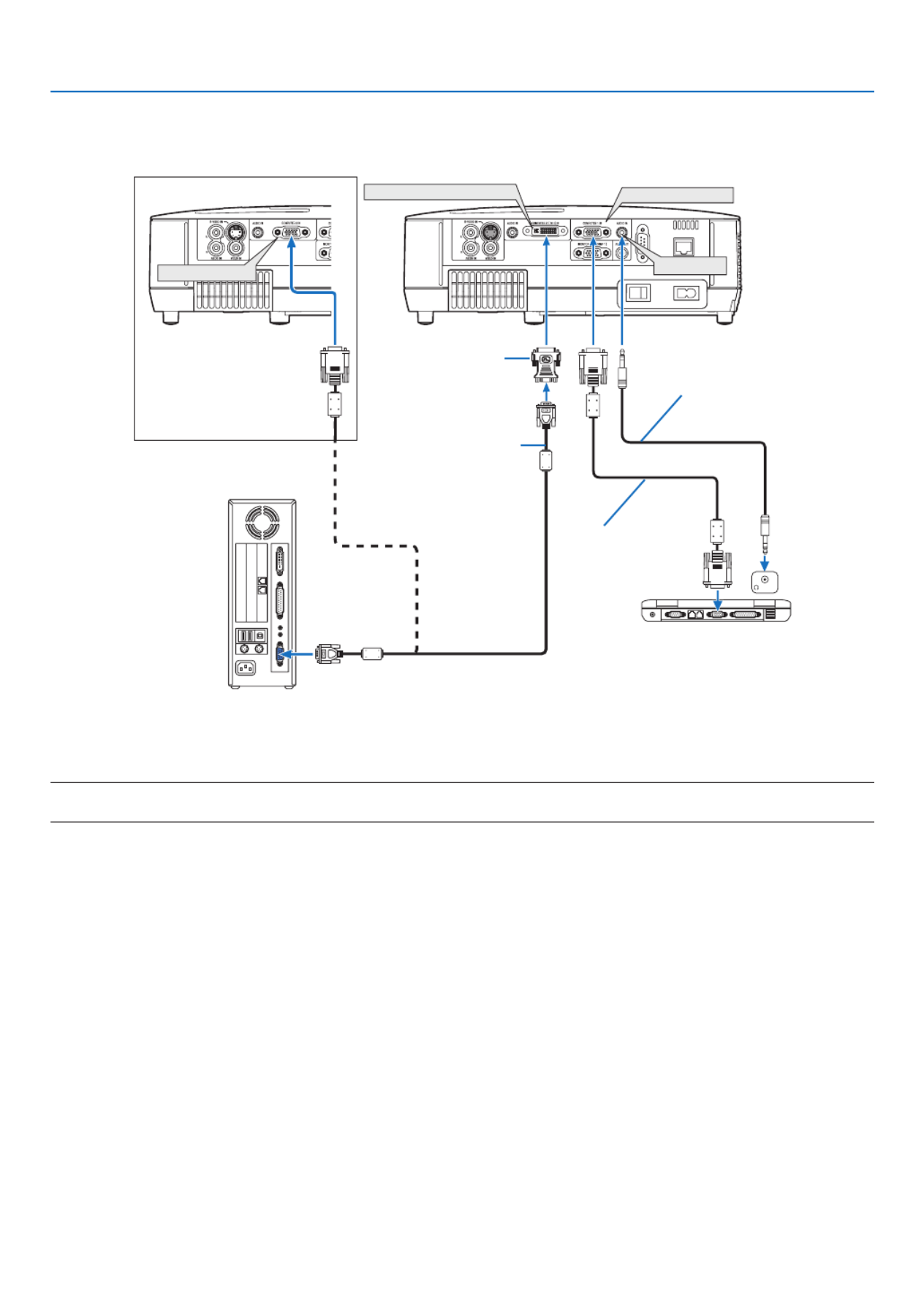
Using Two Analog COMPUTER Inputs Simultaneously
IfyouneedtousetwoanalogCOMPUTERinputssimultaneously,connectaVGAsignalcableasshownbelow.
NP405/NP305
Audio cable (not supplied)

21
2. Installation and Connections
Connecting an External Monitor
Youcanconnectaseparate,externalmonitortoyourprojectortosimultaneouslyviewonamonitorthecomputer
analog image you’re projecting.
NOTE:
• Daisychainconnectionisnotpossible.
• Whenaudioequipmentisconnected,theprojectorspeakerisdisabled.
AUDIO
IN PHONE
MONITOR OUT (COMP 1)
AUDIO OUT
VGA signal
cable (sup-
plied)
VGA signal cable (not supplied)

22
2. Installation and Connections
Connecting Your DVD Player with Component Output
Acomponentsignalwillbeautomaticallydisplayed.Ifnot,fromthemenu,select[SETUP] [OPTIONS(1)]→ →
[SIGNALSELECT] [COMPUTER1],andthenplaceacheckmarkintheComponentradiobutton.→
• Selectthesourcenameforitsappropriateinputconnectorafterturningontheprojector.
[NP610/NP510/NP410/NP310/NP510W/NP410W/NP610S/NP510WS]
Inputconnector SOURCEbuttonontheprojector
cabinet Buttonontheremotecontrol
COMPUTER1IN COMPUTER1 (COMPUTER1)
COMPUTER2(DVI-I)IN COMPUTER2(ANALOG) (COMPUTER2)
[NP405/NP305]
Inputconnector SOURCEbuttonontheprojector
cabinet Buttonontheremotecontrol
COMPUTER1IN COMPUTER1 (COMPUTER1)
COMPUTER2IN COMPUTER2 (COMPUTER2)
NOTE:RefertoyourDVDplayer’sowner’smanualformoreinformationaboutyourDVDplayer’svideooutputrequirements.
AUDIOIN
L R
AUDIOOUT
L R
Component
Y Cb Cr
COMPUTER1IN AUDIOIN
Audio cable (not supplied)
15-pin - to - RCA (fe-
male) × 3 cable adapter
(ADP-CV1E)
Component video RCA × 3
cable (not supplied)
DVD player
Audio Equipment

23
2. Installation and Connections2. Installation and Connections
Connecting Your VCR
• Selectthesourcenameforitsappropriateinputconnectorafterturningontheprojector.
Inputconnector SOURCEbuttonontheprojector
cabinet Buttonontheremotecontrol
VIDEOIN VIDEO (VIDEO)
S-VIDEOIN S-VIDEO (S-VIDEO)
NOTE:TheAUDIOINLandRjacks(RCA)aresharedbetweentheVideoandS-Videoinputs.
NOTE:RefertoyourVCRowner’smanualformoreinformationaboutyourequipment’svideooutputrequirements.
NOTE: An image may not be displayed correctly when a Video or S-Video source is played back in fast-forward or fast-rewind via
a scan converter.
AUDIO IN
L R
AUDIO OUT
L R
VIDEO OUT
S-VIDEO VIDEO
S-VIDEO IN
AUDIO IN
VIDEO IN
Audio cable (not supplied)
S-Video cable (not supplied)
Video cable (not supplied)
VCR
Audio equipment
Audio cable (not supplied)
24
2. Installation and Connections
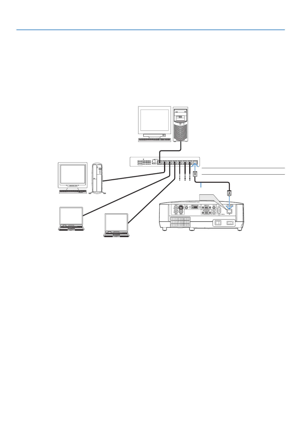
Connecting to a Network (except NP405 and NP305)
TheprojectorcomesstandardwithaLANport(RJ-45)whichprovidesaLANconnectionusingaLANcable.
UsingaLANcableallowsyoutospecifytheNetworkSettingsandtheAlertMailSettingsfortheprojectoroveraLAN.
TouseaLANconnection,youarerequiredtoassignanIPaddresstotheprojectoronthe[PROJECTORNETWORK
SETTINGS]screenofthewebbrowseronyourcomputer.Forsetting,seepage48 49 50, , .
ExampleofLANconnection
ExampleofwiredLANconnection
LAN
Server
Hub
LAN cable (not supplied)
NOTE:UseaCategory5orhigherLANcable.
25
2. Installation and Connections
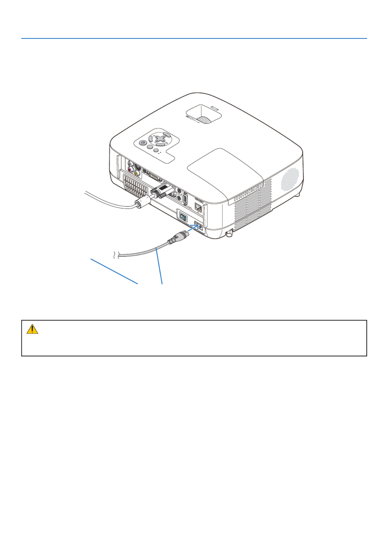
Connecting the Supplied Power Cable
Connectthesuppliedpowercabletotheprojector.
Firstconnectthesuppliedpowercable’stwo-pinplugtotheACINoftheprojector,andthenconnecttheotherplug
ofthesuppliedpowercableinthewalloutlet.
CAUTION:
Donottrytotouchtheventilationoutletontheleftfront(whenseenfromthefront)asitcanbecomeheatedwhile
the projector is turned on and immediately after the projector is turned off.
MENU
EXI
T
ENT ER
ST AT US
LA MP
AUTOAD
J. SO U
RCE
FOCUS
Makesurethattheprongsarefullyinsertedintoboth
the AC IN and the wall outlet.
To wall outlet ←

26
3. Projecting an Image (Basic Operation)
Thissectiondescribeshowtoturnontheprojectorandtoprojectapictureontothescreen.
1 Turning on the Projector
NOTE:
• Theprojectorhastwopowerswitches:amainpowerswitchanda (POWER)button(POWERONandOFFontheremote
control).
• Whenplugginginorunpluggingthesuppliedpowercable,makesurethatthemainpowerswitchispushedtotheoff() posi-
tion.Failuretodosomaycausedamagetotheprojector.
1. Remove the lens cap
• Donotremovethelenscapbypullingonthestring.Doing
so can cause mechanical damage to the part around the
lens.
2. To turn on the main power to the projector, press the
Main Power switch to the on position ( I ).
The projector will go into standby mode. When in standby
mode, the POWER indicator will light orange and the STA-
TUS indicator will light green when [NORMAL] is selected
for [STANDBY MODE].
See the Power Indicator section.( page )→87
FO C
US
FOCU S
ST US AT
LAMP
AUT O ADJ. SOURCE

27
3. Projecting an Image (Basic Operation)
3. Press the (POWER) button on the projector cabinet
or the POWER ON button on the remote control for 1
second.
The POWER indicator will turn to green and the projector
will become ready to use.
NOTE: When the projector is turned on, it may take some time
before the lamp light becomes bright.
TIP:
• WhentheSTATUSindicatorlightsorange,itmeansthatthe
[CONTROLPANELLOCK]isturnedon.(→ page 72)
• Whenthemessage“Projectorislocked!Enteryourpassword.”
isdisplayed,itmeansthatthe[SECURITY]isturnedon.(→
page )43
After you turn on your projector, ensure that the computer
or video source is turned on and that your lens cap is
removed.
NOTE:Whennosignalisavailable,theNEClogo,blue(default),or
black screen will be displayed. When the projector displays the NEC
logo, a blue or black screen, the projector will automatically switch
to[ECOMODE].
TheprojectorwillreturnECOMODEtoitsprevioussettingoncean
active signal is connected.
ST USAT
LAMP
AUTO ADJ.SOURCE
MENU
UP
MAGNIFY PAGE
OFF
POWER
ON
AV-MUTE
DOWN
STATUS
LAMP
AUTO ADJ.SOURCE
Standby Blinking PowerOn
Steady orange light
Blinking green
light
Steady green
light
( page )→87
28
3. Projecting an Image (Basic Operation)
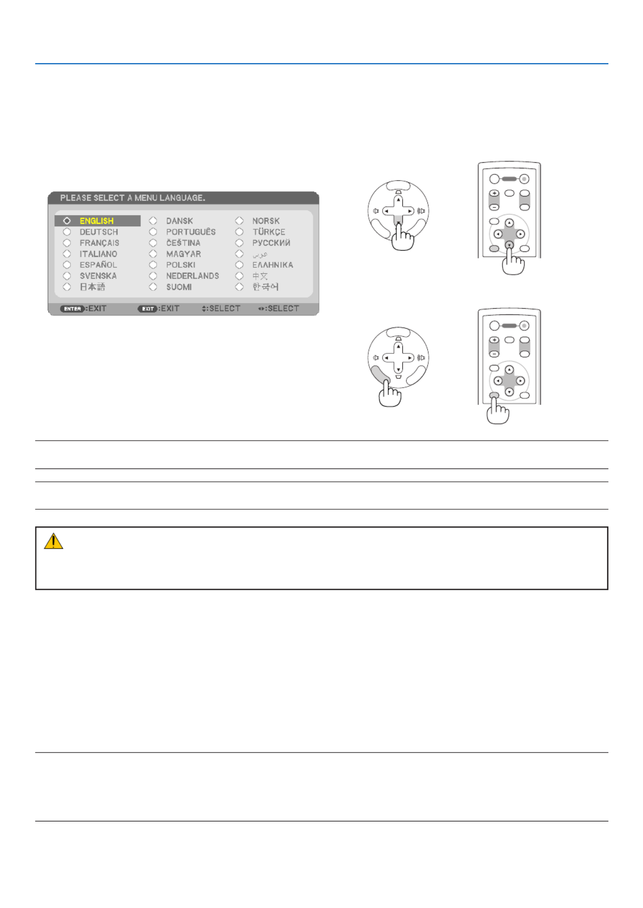
Note on Startup screen (Menu Language Select screen)
Whenyourstturnontheprojector,youwillgettheStartupmenu.Thismenugivesyoutheopportunitytoselectone
of the 21 menu languages.
Toselectamenulanguage,followthesesteps:
1. Use the or button to select one of the 21 , ,
languages from the menu.
2. Press the ENTER button to execute the selection.
After this has been done, you can proceed to the menu
operation.
Ifyouwant,youcanselectthemenulanguagelater.
(→[LANGUAGE]onpage58 70and )
NOTE:Immediatelyafterturningontheprojector,screenickermayoccur.Thisisnormal.Wait3to5minutesuntilthelamplight-
ingisstabilized.
NOTE: If you turn on the projector immediately after the lamp is turned off, the fans run without displaying an image for some time
and then the projector will display the image.
CAUTION:
Theprojectorcannotbeturnedofffor60secondsafterthelampisturnedonandwhilethePOWERindicatorisblinking
green.Doingsocouldcauseprematurelampfailure.
Whenthe[ECOMODE]issetto[ON],theLAMPindicatorwilllightgreen.
Ifoneofthefollowingthingshappens,theprojectorwillnotturnon.
• Ifthe internaltemperature of theprojector istoohigh, theprojectordetects abnormal hightemperature.Inthis
conditiontheprojectorwillnotturnontoprotecttheinternalsystem.Ifthishappens,waitfortheprojector’sinternal
componentstocooldown.
• Whenthelampreachesitsendofusablelife,theprojectorwillnotturnon.Ifthishappens,replacethelamp.
• Ifthelampfailstolight,andiftheSTATUSindicatorashesonandoffinacycleofsixtimes,waitafullminuteand
thenturnonthepower.
NOTE:TurningtheMainPowerSwitchOffthenBackOn
Allowaminimumof1secondbetweenturningoffthemainpowerswitchandturningitbackonagain.
Thesamewillbeappliedwhenapowerstripequippedwithaswitchandabreakerisused.
Failingtodosocouldresultinnopowertotheprojector.(Therewillbenostand-byLED)
Should this happen, unplug the power cable and plug it in again. Turn on the main power switch.
ENTER
EXIT
MENU
UP
MAGNIFY GEPA
OFF
POWER
ON
AV-MUTE
DOWN
ENTER
EXIT
MENU
UP
MAGNIFY GEPA
OFF
POWER
ON
AV-MUTE
DOWN
MENU
EXIT
ENT ER
MENU
EXIT
ENT ER

30
3. Projecting an Image (Basic Operation)
Adjusting the Picture Size and Position
Usetheadjustabletiltfoot,thezoomfunctionorthefocusringtoadjustthepicturesizeandposition.
In this chapter drawings and cables are omitted for clarity.
Adjustingthethrowangle(theheightofanimage)
[Tiltfoot](→ page )31
Adjusting the left and right tilt of an image
[Rearfoot](→ page )31
Finelyadjustingthesizeofanimage
[Zoomfunction](→ page )32
Adjusting the focus
[Focusring](→ page )33
Adjustingthekeystonecorrection[KEYSTONE]*(→ page )34
*Keystonecorrectioncanbealsoperformedautomatically.(→ page )36

31
3. Projecting an Image (Basic Operation)
2
1
3
4
Adjustable Tilt FootAdjustable Tilt
Foot Lever
Adjust the Tilt Foot
1. Lift the front edge of the projector.
CAUTION:
DonottrytotouchtheventilationoutletduringTiltFootadjustment
asitcanbecomeheatedwhiletheprojectoristurnedonandafterit
is turned off.
2. Push up and hold the Adjustable Tilt Foot Lever on the front of
the projector to extend the adjustable tilt foot.
3. Lower the front of the projector to the desired height.
4. Release the Adjustable Tilt Foot Lever to lock the Adjustable tilt
foot.
The tilt foot can be extended up to 1.5 inch/38 mm.
There is approximately 10 degrees (up) of adjustment for the front of
the projector.
Rotate the rear foot to the desired height in order to square the image
on the projection surface.
CAUTION:
• Donotusethetilt-footforpurposesotherthanoriginallyintended.
Misusessuchasusingthetiltfoottocarryorhang(fromthewallor
ceiling) the projector can cause damage to the projector.
Adjustingtheleftandrighttiltofanimage[Rearfoot]
1. Remove the spacer (black rubber) from the rear foot.
Keep the spacer for future use.
2. Rotate the rear foot.
The rear foot can be extended up to 0.4 inch/10 mm. Rotating the rear
foot allows the projector to be placed horizontally.
NOTE:
• Donotextendtherearfootbeyonditsheightlimit(0.4inch/10mm).Doingso
may cause the rear foot to come out of the projector.
• Afterusingtheprojector,attachthespacertotherearfoot.
Spacer(black
rubber)
Rear foot
Up Down
2
1
Adjustable Tilt
Foot Lever

32
3. Projecting an Image (Basic Operation)
FO S CU
FOCUS
Zoom
[NP610/NP510/NP410/NP405/NP310/NP305/NP510W/NP410W]
UsetheZOOMlevertoadjusttheimagesizeonthescreen.
Zoom Lever
[NP610S/NP510WS]
Theimagesizecanbeadjustedelectronicallyfromthemenu.Todoso,followthestepsbelow.
Adjusting from the menu
1. Press the MENU button.
The menu will be displayed.
2. Press the button to select [SETUP] and press the ENTER button.
The [GENERAL] tab will be highlighted.
3. Press the button.
The [DIGITAL ZOOM] will be highlighted.

33
3. Projecting an Image (Basic Operation)
4. Use the or button to adjust the image size.
5. After completing adjustment, press the EXIT button three times.
The menu will be closed.
Focus
[NP610/NP510/NP410/NP405/NP310/NP305/NP510W/NP410W]
UsetheFOCUSringtoobtainthebestfocus.
[NP610S/NP510WS]
UsetheFOCUSlevertoobtainthebestfocus.
FO S CU
FOCUS
Focus Ring
FOCUS
FOCUS
Focus Lever

34
3. Projecting an Image (Basic Operation)
Correcting Keystone Distortion
Correcting Keystone Distortion
Ifthescreenistiltedvertically,keystonedistortionbecomeslarge.Proceedwiththefollowing
stepstocorrectkeystonedistortion
NOTE:
• TheKeystonecorrectioncancauseanimagetobeslightlyblurredbecausethecorrectionismadeelectronically.
• TheKeystonecorrectionrangecanbemadenarrower,dependingonasignaloritsaspectratioselection.
Adjusting with buttons on the cabinet
1. Press the or button with no menus displayed.
Thekeystonebarwillbedisplayed.
MENU
EXIT
ENTER
ST USAT
LAMP
AUTO ADJ.SOURCE
2. Use the or to correct the keystone distortion.
Thekeystonebarwillbeclosedafteraperiodoftime.
3. Press the ENTER button.
Thekeystonebarwillbeclosed.
NOTE:Whenthemenuisdisplayed,theaboveoperationisnotavailable.Whenthemenuisdisplayed,presstheMENUbutton
closethemenuandstarttheKeystonecorrection.
Fromthemenu,select[SETUP] [GENERAL] [KEYSTONE].Thechangescanbesavedwith[KEYSTONESAVE].(→ → → pag
68)

35
3. Projecting an Image (Basic Operation)
Adjusting from the menu
1. Press the MENU button.
The menu will be displayed.
2. Press the button to select [SETUP] and press the ENTER button.
The [GENERAL] screen will be displayed.
3. Press the button to select [KEYSTONE].
4. Press the or button.
Adjust so that the image is rectangular.
5. After completing adjustment, press the EXIT button three times.
The menu will be closed.
NOTE:TheKeystonecorrectioncancauseanimagetobeslightlyblurredbecausethecorrectionismadeelectronically.
TIP:Thechangescanbesavedwith[KEYSTONESAVE].(→ page 36, 68)

36
3. Projecting an Image (Basic Operation)
Adjusting with the Auto Keystone Function
TheAutoKeystonecorrectionfeaturewillcorrecttheverticaldistortionofaprojectedimageonthescreen.Nospecial
operationrequired.Justputtheprojectoronaatsurface.
TIP:Evenwhenthemenusettingfor[AUTOKEYSTONE]isturnedon,[KEYSTONE]canbeadjustedmanually.
Toturnon[AUTOKEYSTONE],proceedthefollowingsteps.
1. Press the MENU button
The menu will be displayed.
2. Press the button to select [SETUP] and press the ENTER button.
The [GENERAL] screen will be highlighted.
3. Press the button.
The [AUTO KEYSTONE] will be highlighted.
4. Press the ENTER button to display the [AUTO KEYSTONE] screen.
5. Press the or button to select [ON] and press the ENTER button.
6. Press the MENU button.
The menu will be closed.
NOTE:
• Themaximumrangeofverticalkeystonecorrectionis+/−30degreesontheNP610/NP510/NP410/NP405/NP310/NP305/NP510W/
NP410Wand+/−20degreesontheNP610S/NP510WS.
Themaximumrangeofkeystonecorrectionmaybelowerdependingonthesignaloraspectratioselection.
Therangeofkeystonecorrectionisnotthemaximumtiltangleofprojector.
• TheAutoKeystonecorrectionwilltakeeffectin2secondsafterchangingtheprojectionangleduringprojection.
• Theleftandright(horizontal)keystonecorrectionisnotavailable.
Place the projector so that the lens surface is parallel to the screen.
The rear feet of the projector can be adjusted to level the projector.
• Usingkeystonecorrectioncancausetheimagetobeslightlyblurredbecausethecorrectionismadeelectronically.
TIP:Ifyouhaveoneofthefollowingconditions,theprojector’sAutoKeystonemaynotbeperformedcorrectly.
• Thescreenistilted
• Theroomtemperatureistoohighortoolow
• Theopticalzoomismaximizedorminimized
37
3. Projecting an Image (Basic Operation)
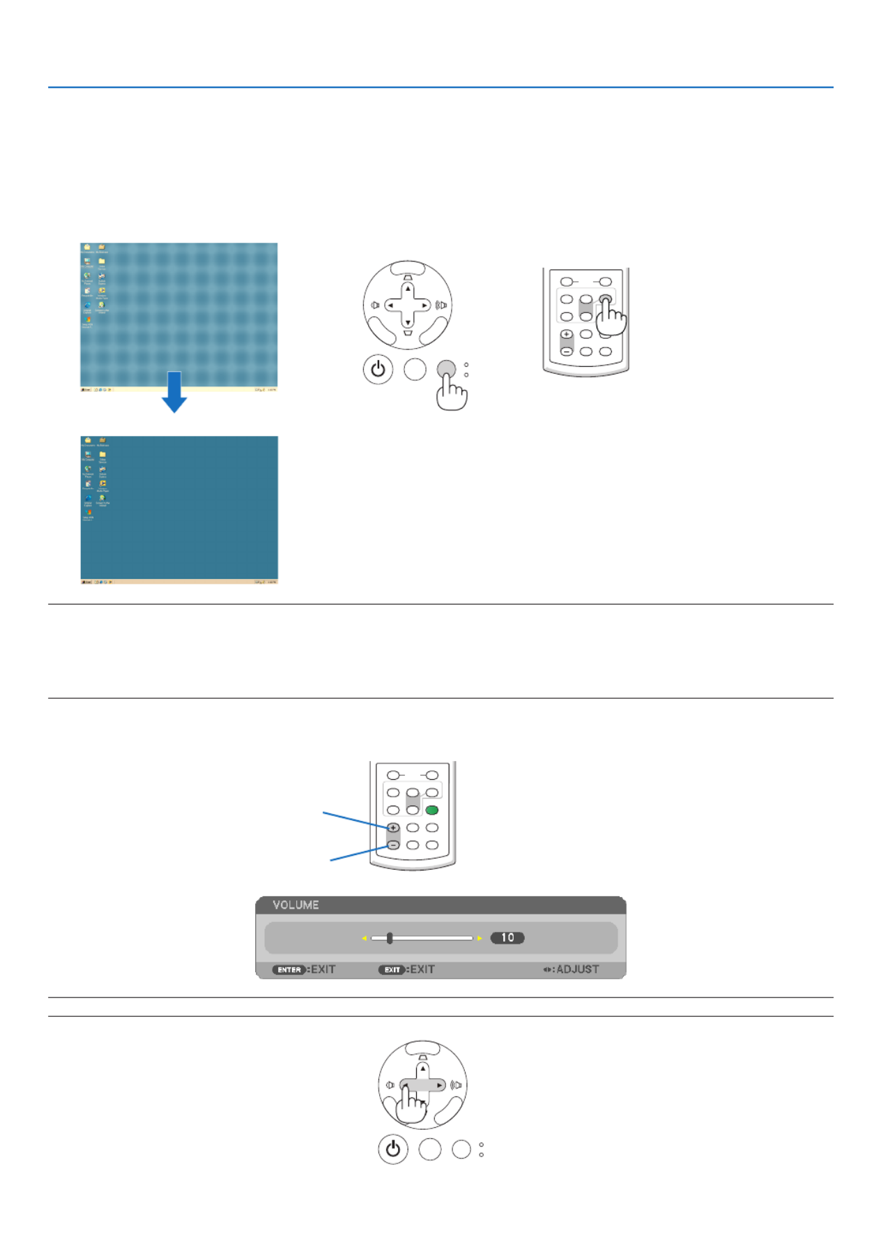
Optimizing Computer Signal Automatically
Adjusting the Image Using Auto Adjust
Optimizingacomputerimageautomatically.
PresstheAUTOADJ.buttontooptimizeacomputerimageautomatically.
Thisadjustmentmaybenecessarywhenyouconnectyourcomputerforthersttime.
[Poor picture]
[Normal picture]
VOLUME
L-CLICK
MOUSE
R-CLICK
ASPECT HELP
FREEZEPICTURE
AUTO ADJ.
S-VIDEO
VIDEO
COMPUTER
ECO MODE
1
2
Increase volume
Decrease volume
VOLUME
L-CLICK
MOUSE
R-CLICK
ASPECT HELP
FREEZEPICTURE
AUTO ADJ.
S-VIDEO
VIDEO
COMPUTER
ECO MODE
1
2
NOTE:
Some signals may take time to display or may not be displayed correctly.
• TheAutoAdjustfunctiondoesnotworkforcomponent,video,andDVIdigitalsignals.
• IftheAutoAdjustoperationcannotoptimizethecomputersignal,trytoadjust[HORIZONTAL],[VERTICAL],[CLOCK],and[PH
manually.(→ page 64, 65)
Turning Up or Down Volume
Soundlevelfromthespeakercanbeadjusted.
TIP: When no menus appear, the and buttons on the projector cabinet work as a volume control.
MENU
EXIT
ENTER
ST USAT
LAMP
AUTO ADJ.SOURCE
MENU
EXIT
ENTER
ST USAT
LAMP
AUTO ADJ.SOURCE

38
3. Projecting an Image (Basic Operation)
7 Turning off the Projector
MENU
EXIT
ENTER
ST UAT
LAMP
AUTO ADJ.SOURCE
ENTER
EXIT
MENU
UP
MAGNIFY PAGE
OFF
POWER
ON
AV-MUTE
DOWN
Toturnofftheprojector:
1. First, press the (POWER) button on the projector
cabinet or the POWER OFF button on the remote con-
trol.
The [POWER OFF / ARE YOU SURE? / CARBON SAV-
INGS- SESSION 0.000[g-CO2]] message will appear.
2. Secondly, press the ENTER button or press the
(POWER) or the POWER OFF button again.
The lamp will turn off and the projector will go into standby
mode. When in standby mode, the POWER indicator will
light orange and the STATUS indicator will light green when
[NORMAL] is selected for [STANDBY MODE].
Immediately after turning on the projector and displaying an
image, you cannot turn off the projector for 60 seconds.
3. Finally, turn off the Main Power switch.
The POWER indicator will go out.
NOTE:Donotturnoffthemainpowerwithin10secondsofmaking
adjustment or setting changes and closing the menu.
Doingsocancauselossofadjustmentsandsettings.
PowerOn
Steady green
light
CAUTION:
Partsoftheprojectorwillbecomeheatedduringoperation.Usecautionwhenpickinguptheprojectorimmediately
after it has been operating.
CAUTION:
Theprojectorcannotbeturnedofffor60secondsafterthelampisturnedonandwhilethePOWERindicatoris
blinkinggreen.Doingsocouldcauseprematurelampfailure.
Standby
Steady
orange light
39
3. Projecting an Image (Basic Operation)
After Use
Preparation:Makesurethattheprojectoristurnedoff.
1. Unplug the power cable.
2. Disconnect any other cables.
3. Retract adjustable tilt foot if extended.
4. Cover the lens with the lens cap.
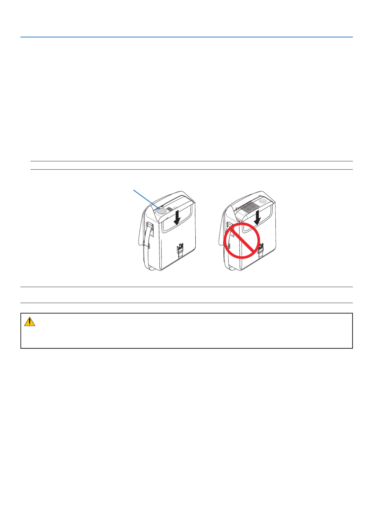
5. Put the projector and accessories in the supplied soft case.
Place the projector in the soft case with the lens facing upward as shown below. This is to prevent the lens from
damage.
NOTE:TheNP610S,theNP510WS,theNP405,andtheNP305donotcomewithasoftcase.
NOTE:Whenplacingtheprojectorinthesoftcase,retractthetiltfootandtherearfeet.Failuretodosomaycasedamagetoth
projector.
CAUTION:
Usecautionwhenputtingtheprojectorinthesoftcaseimmediatelyaftertheprojectorhasbeenoperating.The
projector cabinet is hot.
Insert the projector with the lens
facing upward

40
1 Turning off the Image and Sound
PresstheAV-MUTEbuttontoturnofftheimageandsoundforashort
period of time. Press again to restore the image and sound.
NOTE:
• Even though the image is turned off, the menu still remains on the screen.
• SoundfromtheAUDIOOUTjack(Stereomini)canbeturnedoff.
Freezing a Picture
Pressthe FREEZEbuttonto freezeapicture. Pressagaintoresume
motion.
NOTE:Theimageisfrozenbuttheoriginalvideoisstillplayingback.
Enlarging a Picture
Youcanenlargethepictureuptofourtimes.
NOTE:Themaximummagnicationmaybelessthanfourtimesdependingon
the signal.
Todoso:
1. Press the MAGNIFY (+) button to magnify the picture.
To move the magnied image, use the , , or button.
4. Convenient Features
ENTER
EXIT
MENU
UP
MAGNIFY PAGE
OFF
POWER
ON
AV-MUTE
DOWN
ENTER
EXIT
MENU
UP
MAGNIFY PAGE
OFF
POWER
ON
AV-MUTE
DOWN
ENTER
EXIT
MENU
UP
MAGNIFY PAGE
OFF
POWER
ON
AV-MUTE
DOWN
VOLUME ASPECT HELP
FREEZEPICTURE
S-VIDEO
ECO MODE
2
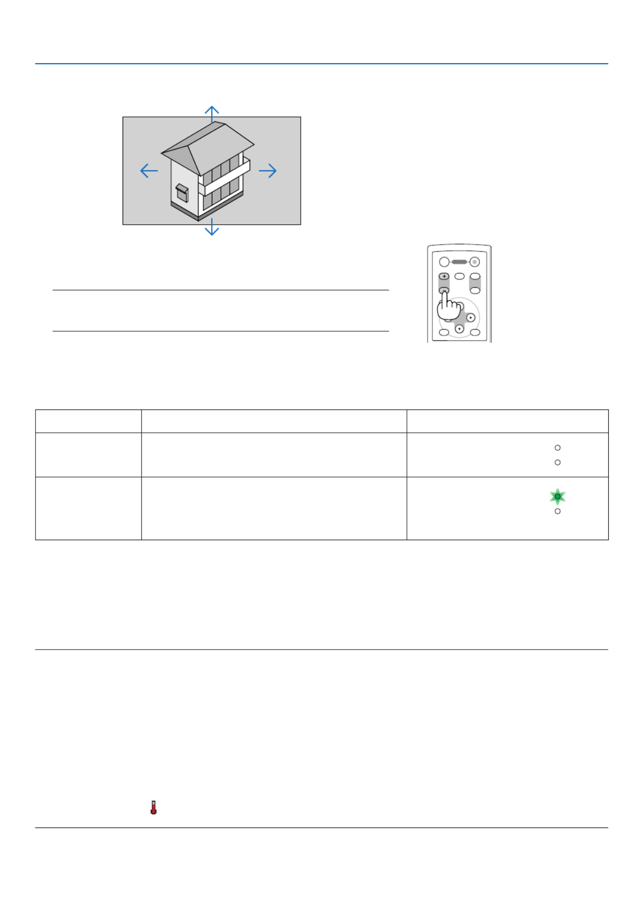
41
4. Convenient Features
Changing Eco Mode
Thisfeatureenablesyoutoselecttwobrightnessmodesofthelamp:
OFFandONmodes.Thelamplifecanbeextendedbyturningonthe[ECOMODE].
[ECOMODE] Description StatusofLAMPindicator
[OFF] Thisisthedefaultsetting(100%Brightness). Off
STATUS
LAMP
[ON] Select this mode to increase the lamp life (approx.
70% Brightness on NP610/NP510W/NP410W/
NP610S/NP510WSandapprox.80%Brightnesson
NP510/NP410/NP405/NP310/NP305).
Steady Green light
STATUS
LAMP
Toturnonthe[ECOMODE],dothefollowing:
1. Press the ECO MODE button on the remote control to display [ECO MODE] screen.
2. Use the or button to select [ON].
3. Press the ENTER button.
Tochangefrom[ON]to[OFF],GobacktoStep2andselect[OFF].RepeatStep3.
NOTE:
• The[ECOMODE]canbechangedbyusingthemenu.
Select[SETUP] [GENERAL] [ECOMODE].→ →
• Thelampliferemainingandlamphoursusedcanbecheckedin[USAGETIME].Select[INFO.] [USAGETIME].→
• Theprojectorisalwaysin[ON]for90secondsafterthelampisturnedonandwhilethePOWERindicatorisblinkinggreen.T
lampconditionwillnotbeaffectedevenwhen[ECOMODE]ischanged.
• Afteralapseof1minutefromwhentheprojectordisplaysablue,blackorlogoscreen,[ECOMODE]willautomaticallyswitch
[ON].Theprojectorwillreturntothe[OFF]onceasignalisaccepted.
• Iftheprojectorisoverheatedin[OFF]mode,theremaybeacasewherethe[ECOMODE]automaticallychangesto[ON]mo
toprotecttheprojector.Whentheprojectorisin[ON]mode,thepicturebrightnessdecreases.Whentheprojectorcomesback
tonormaltemperature,the[ECOMODE]returnsto[OFF]mode.
Thermometer symbol [ ]indicatesthe[ECOMODE]isautomaticallysetto[ON]modebecausetheinternaltemperatureistoo
high.
2. Press the button.
The area of the magnied image will be moved
3. Press the MAGNIFY (−) button.
Each time the MAGNIFY (−) button is pressed, the image is re-
duced.
NOTE:
• Theimagewillbeenlargedorreducedatthecenterofthescreen.
• Displayingthemenuwillcancelthecurrentmagnication.
ENTER
EXIT
MENU
UP
MAGNIFY PAGE
OFF
POWER
ON
AV-MUTE
DOWN
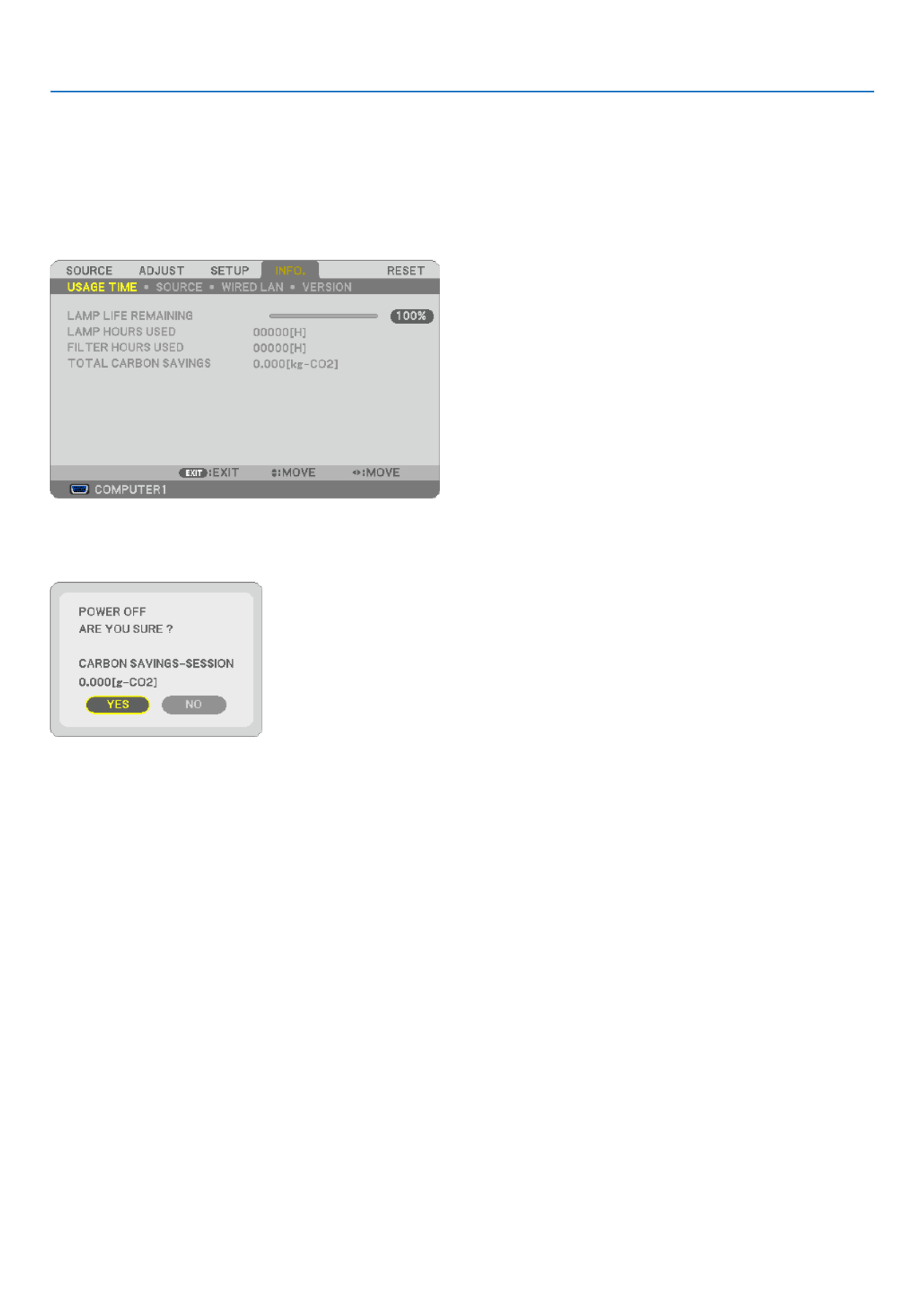
42
4. Convenient Features
Checking Energy-Saving Effect [CARBON METER]
Thisfeaturewillshowenergy-savingeffectintermsofCO2emissionreduction(kg)whentheprojector’s[ECOMODE]
issetto[ON].Thisfeatureiscalledas[CARBONMETER].
Therearetwomessages:[TOTALCARBONSAVINGS]and[CARBONSAVINGS-SESSION].The[TOTALCARBON
SAVINGS]messageshowsthetotalamountofCO2emissionreductionfromthetimeofshipmentuptonow.Youcan
checktheinformationon[USAGETIME]from[INFO.]ofthemenu.(→ page )78
The[CARBONSAVINGS-SESSION]messageshowstheamountofCO2emissionreductionbetweenthetimeof
changingtoECOMODEimmediatelyafterthetimeofpower-onandthetimeofpower-off.The[CARBONSAVINGS-
SESSION]messagewillbedisplayedinthe[POWEROFF/AREYOUSURE?]messageatthetimeofpower-off.
TIP:
• TheformulaasshownbelowisusedtocalculatetheamountofCO2emissionreduction.
AmountofCO2emissionreduction=PowerconsumptioninOFFforECOMODE–PowerconsumptioninONforECOMO
CO2conversionfactor.*
*CalculationforamountofCO2emissionreductionisbasedonanOECDpublication“CO2EmissionsfromFuelCombustio
2008Edition”.
• Thisformulawillnotapplytothepowerconsumptionwhichisnotaffectedbywhether[ECOMODE]isturnedonoroff.

44
4. Convenient Features
7. Type in the same combination of buttons and press the ENTER button.
The conrmation screen will be displayed.
8. Select [YES] and press the ENTER button.
The SECURITY function has been enabled.
Toturnontheprojectorwhen[SECURITY]isenabled:
1. Press and hold the POWER button for about 1 second.
Theprojectorwillbeturnedonanddisplayamessagetotheeffectthattheprojectorislocked.
2. Press the MENU button.
3. Type in the correct keyword and press the ENTER button. The projector will display an image.
NOTE: The security disable mode is maintained until the main power is turned off or unplugging the power cable.
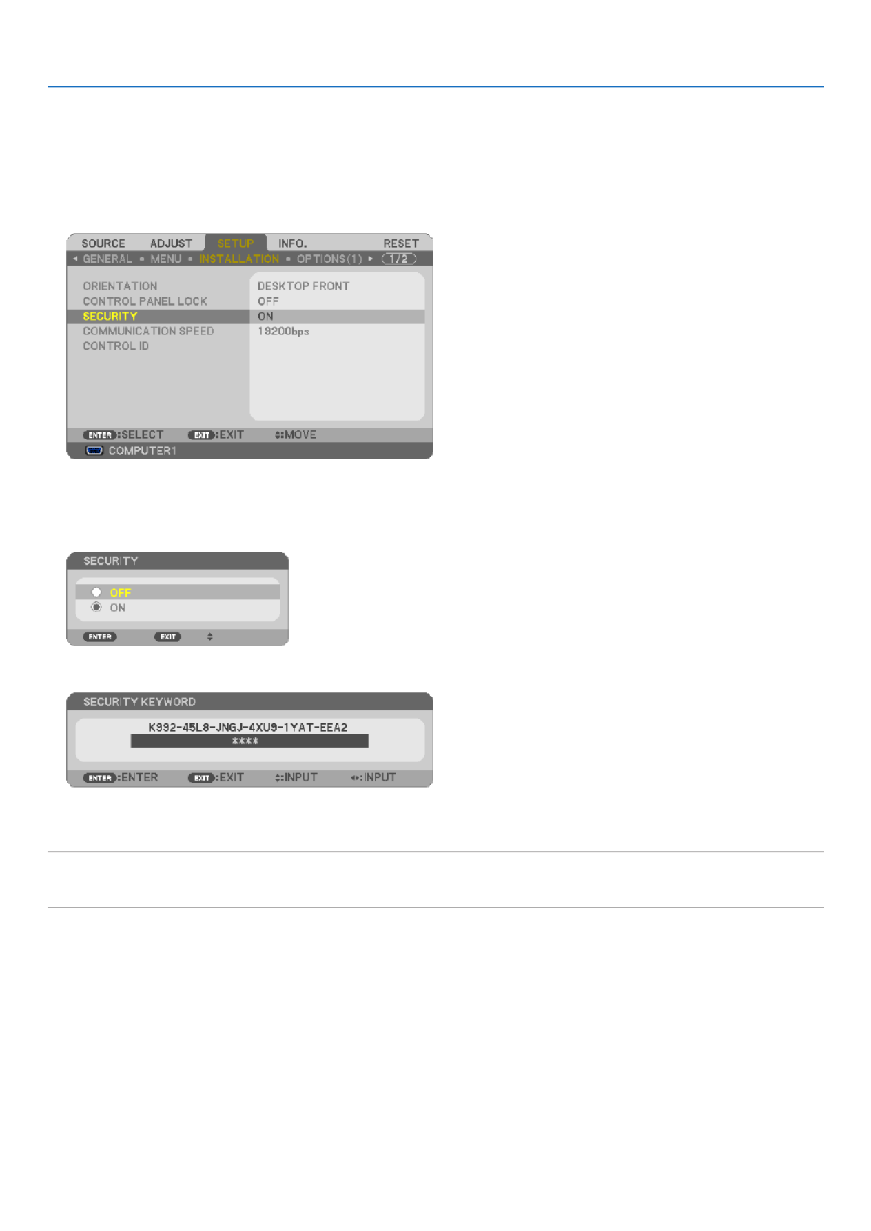
45
4. Convenient Features
TodisabletheSECURITYfunction:
1. Press the MENU button.
The menu will be displayed.
2. Select [SETUP] [INSTALLATION] [SECURITY] and press the ENTER button.→ →
The OFF/ON menu will be displayed.
3. Select [OFF] and press the ENTER button.
The KEYWORD CONFIRMATION screen will be displayed.
4. Type in your keyword and press the ENTER button.
Whenthecorrectkeywordisentered,theSECURITYfunctionwillbedisabled.
NOTE:Ifyouforgetyourkeyword,contactyourdealer.Yourdealerwillprovideyouwithyourkeywordinexchangeforyourrequ
code.YourrequestcodeisdisplayedintheKeywordConrmationscreen.Inthisexample[K992-45L8-JNGJ-4XU9-1YAT-EEA2]
arequestcode.

46
4. Convenient Features
30˚
30˚
7 Using the Optional Remote Mouse Receiver (NP01MR)
The optional remote mouse receiver enables you to operate your computer’s mouse functions from the remote control.
Itisagreatconvenienceforclickingthroughyourcomputer-generatedpresentations.
Connectingtheremotemousereceivertoyourcomputer
Ifyouwishtousetheremotemousefunction,connectthemousereceiverandcomputer.
Themousereceivercanbeconnecteddirectlytothecomputer’sUSBport(typeA).
NOTE:DependingonthetypeofconnectionorOSinstalledonyourcomputer,youmayhavetorestartyourcomputerorchange
your computer settings.
Whenoperatingacomputerviatheremotemousereceiver
WhenconnectingusingtheUSBterminal
ForPC,themousereceivercanonlybeusedwithaWindows98/Me/XP*,Windows2000,WindowsVista,orMacOS
X10.0.0orlateroperatingsystem.
*NOTE:InSP1orolderversionofWindowsXP,ifthemousecursorwillnotmovecorrectly,dothefollowing:
CleartheEnhancepointerprecisioncheckboxunderneaththemousespeedsliderintheMousePropertiesdialogbox[Pointer
Optionstab].
NOTE:ThePAGEUPandDOWNbuttonsdonotworkwithPowerPointforMacintosh.
NOTE:Waitatleast5secondsafterdisconnectingthemousereceiverbeforereconnectingitandviceversa.Thecomputermaynot
identify the mouse receiver if it is repeatedly connected and disconnected in rapid intervals.
Remote mouse receiver
Computer
To USB port of PC or Macintosh
Remote sensor on the
remote mouse receiver
7m/22 feet

47
4. Convenient Features
Operatingyourcomputer’smousefromtheremotecontrol
Youcanoperateyourcomputer’smousefromtheremotecontrol.
PAGEUP/DOWNButton: scrollstheviewingareaofthewindowortomovetothepreviousornextslideinPower-
Point on your computer.
Buttons: movesthemousecursoronyourcomputer.
MOUSEL-CLICKButton: worksasthemouseleftbutton.
MOUSER-CLICKButton:worksasthemouserightbutton.
NOTE:
• Whenyouoperatethecomputerusingthe or button with the menu displayed, both the menu and the mouse pointer
will be affected. Close the menu and perform the mouse operation.
• ThePAGEUPandDOWNbuttonsdonotworkwithPowerPointforMacintosh.
AboutDragMode:
BypressingtheMOUSEL-CLICKorR-CLICKbuttonfor2or3secondsthenreleasing,thedragmodeissetandthe
drag operation can be performed simply by pressing the button.Todroptheitem,presstheMOUSEL-CLICK
(orR-CLICK)button.Tocancelit,presstheMOUSER-CLICK(orL-CLICK)button.
TIP:YoucanchangethePointerspeedontheMousePropertiesdialogboxontheWindows.Formoreinformation,seetheuser
documentation or online help supplied with your computer.

48
4. Convenient Features
Network Setting by Using an HTTP Browser (except NP405
and NP305)
Overview
ConnectingtheprojectortoanetworkallowstheAlertMailsetting(→ page ) and the projector control from a 50
computerviathenetwork.
Toperformtheprojectorcontrolfromawebbrowser,youmusthaveanexclusiveapplicationinstalledonyourcom-
puter.
TheIPaddressandsubnetmaskoftheprojectorcanbesetontheNetworkSettingscreenofthewebbrowserby
usinganHTTPserverfunction.Pleasebesuretouse“MicrosoftInternetExplorer6.0”orahigherversionfortheweb
browser.(Thisdeviceuses“JavaScript”and“Cookies”andthebrowsershouldbesettoacceptthesefunctions.The
settingmethodwillvarydependingontheversionofbrowser.Pleaserefertothehelplesandtheotherinformation
providedinyoursoftware.)
AccessisgainedtotheHTTPserverfunctionbystartingtheWebbrowseronthecomputerviathenetworkconnected
totheprojectorandenterthefollowingURL.
• NetworkSetting
http://<theprojector’sIPaddress>/index.html
• AlertMailSetting
http://<theprojector’sIPaddress>/lancong.html
TIP:
• ThedefaultIPaddressis“192.168.0.10”.
• Theexclusiveapplicationcanbedownloadedfromourwebsite.
NOTE:
• IfthePROJECTORNETWORKSETTINGSscreendoesnotappearinthewebbrowser,presstheCtrl+F5keystorefreshyour
browser(orclearthecache).
• Thedisplay’sorbutton’sresponsecanbesloweddownoroperationmaynotbeaccepteddependingthesettingsofyournetwork.
Should this happen, consult your network administrator.
The projector may not respond if its buttons are repeatedly pressed in rapid intervals. Should this happen, wait a moment and
repeat.Ifyoustillcan’tgetanyresponse,turnoffandbackontheprojector.
Preparation Before Use
ConnecttheprojectortoacommerciallyavailableLANcablebeforeengaginginbrowseroperations.(→ page )24
Operationwithabrowserthatusesaproxyservermaynotbepossibledependingonthetypeofproxyserverandthe
settingmethod.Althoughthetypeofproxyserverwillbeafactor,itispossiblethatitemsthathaveactuallybeenset
willnotbedisplayeddependingontheeffectivenessofthecache,andthecontentssetfromthebrowsermaynotbe
reectedinoperation.Itisrecommendedthataproxyservernotbeusedunlessitisunavoidable.
HandlingoftheAddressforOperationviaaBrowser
RegardingtheactualaddressthatisenteredfortheaddressorenteredtotheURLcolumnwhenoperationofthepro-
jectorisviaabrowser,thehostnamecanbeusedasitiswhenthehostnamecorrespondingtotheIPaddressofthe
projectorhasbeenregisteredtothedomainnameserverbyanetworkadministrator,orthehostnamecorresponding
totheIPaddressoftheprojectorhasbeensetinthe“HOSTS”leofthecomputerbeingused.
Example1: Whenthehostnameoftheprojectorhasbeensetto“pj.nec.co.jp”,accessisgainedtothenetwork
setting by specifying
http://pj.nec.co .jp/index.html
fortheaddressortheentrycolumnoftheURL.
Example2: WhentheIPaddressoftheprojectoris“192.168.73.1”,accessisgainedtothemailalertsettingsby
specifying
http://192.168.73.1/inde x.html
fortheaddressortheentrycolumnoftheURL.

49
4. Convenient Features
NetworkSettings
http://<the projector’s IP address> /index.html
DHCP ..................................Enabling this option automatically assigns an IP address to the projector from your DHCP server.
Disabling this option allows you to register the IP address or subnet mask number obtained from
your network administrator.
TIP:YoucanchecktheIPaddressinthemenuwhen[ENABLE]isselectedfor[DHCP].Todoso
fromthemenu,select[INFO.] [WIREDLAN].→
IP ADDRESS .......................Set your IP address of the network connected to the projector when [DISABLE] is selected for
[DHCP].
TIP:YoucancheckyourspeciedIPaddressinthemenu.Todoso,fromthemenu,select[INFO.]
→[WIREDLAN].
SUBNET MASK ...................Set your subnet mask number of the network connected to the projector when [DISABLE] is selected
for [DHCP].
DEFAULT GATEWAY
................Set your default gateway of the network connected to the projector when [DISABLE] is selected for
[DHCP].
DNS (PRIMARY) .................Set your primary DNS settings of the network connected to the projector.
DNS (SECONDARY) .................
Set your secondary DNS settings of the network connected to the projector.
UPDATE ..............................Reect your settings.
NOTE:Close thebrowser afterclicking [UPDATE].The projector will automaticallyupdate you
settings.
TIP:Selecting[NETWORKSETTINGS]for[RESET]fromtheprojector’smenuallowsyoutoreturnthefollowingitemstothefac
default.
[DHCP]:DISABLE
[IPADDRESS]:192.168.0.10
[SUBNETMASK]:255.255.255.0
[DEFAULTGATEWAY]:192.168.0.1
*[DNS(PRIMARY)]and[DNS(SECONDARY)]willremainunchanged.

50
4. Convenient Features
AlertMailSetting
http://<the projector’s IP address>/lancong.html
Thisoptionnotiesyourcomputerofanerrormessageviae-mailwhenusingwiredLAN.Anerrormessagenotication
willbesentwhentheprojectorlamphasreachedtheendofitsusablelifeoranerroroccursintheprojector.
HOST NAME ............................ Type in the hostname of the network connected to the projector. Up to 60 alphanumeric char-
acters can be used. If the host name is unknown, type in a string of characters representing the
projector. Example: Projector 1
DOMAIN NAME ........................ Type in the domain name of the network connected to the projector. Up to 60 alphanumeric
characters can be used. If the domain name is unknown, type in the right side of @ in the sender’s
address. Example: nec. com
ALERT MAIL ............................. Checking [ENABLE] will turn on the Alert Mail feature.
Checking [DISABLE] will turn off the Alert Mail feature.
SENDER’S ADDRESS ................ Type in the senders address. Up to 60 alphanumeric and symbols characters can be used.
SMTP SERVER NAME ............... Type in the SMTP server name to be connected to the projector. Up to 60 alphanumeric characters
can be used.
RECIPIENT’S ADDRESS 1 to 3
.... Type in your recipient’s address. Up to 60 alphanumeric and symbols characters can be used.
APPLY ....................................... Click this button to reect the above settings
EXECUTE .................................. Click this button to send a test mail to check if your settings are correct.
STATUS ..................................... A reply to a test mail will be displayed.
NOTE:
• Ifyouexecuteatest,youmaynotreceiveanAlertmail.Shouldthishappen,checkifthenetworksettingsarecorrect.
• Ifyouenteredanincorrectaddressinatest,youmaynotreceiveanAlertmail.Shouldthishappen,checkiftheRecipient’sA
dress is correct
TIP:TheAlertMailsettingswillnotbeaffectedevenwhen[RESET]isdonefromthemenu.

51
4. Convenient Features
9 Using the VGA Signal Cable to Operate the Projector
(Virtual Remote)
Usingtheutilitysoftware“VirtualRemoteTool”includedonthecompanionNECProjectorCD-ROM,VirtualRemote
screen (or toolbar) can be displayed on your computer screen.
Thiswillhelpyouperformoperationssuchasprojector’spoweronoroffandsignalselectionviatheVGAsignal
cable.
VirtualRemotescreen Toolbar
ThissectionprovidesanoutlineofpreparationforuseofVirtualRemoteTool.
ForinformationonhowtouseVirtualRemoteTool,seeHelpofVirtualRemoteTool.(→ page )55
Step1:InstallVirtualRemoteToolonthecomputer.(→ page , )51 52
Step2:Connecttheprojectortothecomputer.(→ page )53
Step3:StartVirtualRemoteTool.(→ page )54
NOTE:
• When[COMPUTER1]isselectedfromyoursourceselection,theVirtualRemotescreenorthetoolbarwillbedisplayedaswe
as your computer screen.
• UsethesuppliedVGAsignalcabletoconnecttheCOMPUTER1INconnectordirectlywiththemonitoroutputconnectorof
computer to use Virtual Remote Tool.
UsingaswitcherorothercablesthanthesuppliedVGAsignalcablemaycausefailureinsignalcommunication.
VGAcableconnector:
PinNos.12and15arerequiredforDDC/CI.
• VirtualRemoteToolmaynotworkdependingonyourcomputer’sspecicationsandversionofgraphicadaptersordrivers.
TIP:
• Theprojector’sCOMPUTER1INconnectorsupportsDDC/CI(DisplayDataChannelCommandInterface).DDC/CIisastand
interfaceforbidirectionalcommunicationbetweendisplay/projectorandcomputer.
• ForupdateinformationonVirtualRemoteTool,visitourwebsite:http://www.nec-display.com/dl/en/index.html
Step 1: Install Virtual Remote Tool on the computer
Supported OS
VirtualRemoteToolwillrunonthefollowingoperatingsystems.
WindowsVistaHomeBasic* 1,WindowsVistaHomePremium* 1,WindowsVistaBusiness* 1,
WindowsVistaEnterprise* 1,WindowsVistaUltimate* 1
WindowsXPHomeEdition* 2
,WindowsXPProfessional* 2,Windows2000Professional* 2
*1:Supports32-bitversion.
*2:TorunVirtualRemoteTool,“Microsoft.NETFrameworkVersion2.0orlater”isrequired.TheMicrosoft.NET
FrameworkVersion2.0orlaterisavailablefromMicrosoft’swebpage.InstalltheMicrosoft.NETFramework
Version2.0orlateronyourcomputer.Windows2000ProfessionalsupportsMicrosoft.NETFrameworkVer-
sion 2.0 only.

52
4. Convenient Features
InstallVirtualRemoteTool
Preparation:
ExitallrunningprogramsbeforeinstallingVirtualRemoteTool.Ifanotherprogramisrunning,theinstallationmaynot
becompleted.ToinstallVirtualRemoteTool,theWindowsuseraccountmusthave[Administrator]privilege(Windows
VistaandWindows2000)or[ComputerAdministrator]privilege(WindowsXP).
1 Insert the accompanying NEC Projector CD-ROM into your CD-ROM drive.
ThefoldersinNECProjectorCD-ROMwillbedisplayed.Ifthefoldersarenotdisplayed,right-clicktheCD/DVD
drive icon in Windows’ “Computer” (or “My Computer”) and select “Open”.
2 Double-click “software” and then “Virtual Remote Tool”.
The “setup.exe” icon will be displayed.
3 Double-click the “setup.exe” icon.
The Installer will start and the Wizard screen will appear.
4 Click “Next”.
“END USER LICENSE AGREEMENT” screen will be displayed.
Read “END USER LICENSE AGREEMENT” carefully.
5 If you agree, click “I accept the terms in the license agreement” and then click “Next”.
Follow the instructions on the installer screens to complete the installation.
After the installation is completed, the shortcut icon forVirtualRemoteToolwillbeplacedonthedesktop.

53
4. Convenient Features
TIP:
UninstallingVirtualRemoteTool
Preparation:
ExitVirtualRemoteToolbeforeuninstalling.TouninstallVirtualRemoteTool,theWindowsuseraccountmusthave
“Administrator”privilege(WindowsVistaandWindows2000)or“ComputerAdministrator”privilege(WindowsXP).
•ForWindowsVista
1 Click “Start” and then “Control Panel”.
The Control Panel window will be displayed.
2 Click “Uninstall a program” under “Programs”
The “Programs and Features” window will be displayed.
3 Select Virtual Remote Tool and click it.
4 Click “Uninstall/Change” or “Uninstall”.
•Whenthe“UserAccountControl”windowsisdisplayed,click“Continue”.
Follow the instructions on the screens to complete the uninstallation.
•ForWindowsXP/2000
1 Click “Start” and then “Control Panel”.
The Control Panel window will be displayed.
2 Double-click “Add / Remove Programs”.
The Add / Remove Programs window will be displayed.
•OnWindows2000,double-click“Uninstallaprogram”.
3 Click Virtual Remote Tool from the list and then click “Remove”.
Follow the instructions on the screens to complete the uninstallation.
Step 2: Connect the projector to the computer
1 Use the supplied VGA signal cable to connect the COMPUTER 1 IN connector of the projector directly with
the monitor output connector of the computer.
2 Connect the supplied power cable to the AC IN of the projector and the wall outlet, and then press the Main
Power switch to turn on the main power.
The projector is in the standby condition.
COMPUTER 1 IN
TIP:
• WhenVirtualRemoteToolstartsforthersttime,“EasySetup”windowwillbedisplayedtonavigateyourconnections.
ACInput
MainPowerSwitch
VGA signal cable (supplied)
→ To wall outlet
Power cable (supplied)

54
4. Convenient Features
Step 3: Start Virtual Remote Tool
1 Double-click the shortcut icon on the Windows Desktop.
When Virtual Remote Tool starts for the rst time, “Easy Setup” window will be displayed.
Follow the instructions on the screens
When “Easy Setup” is completed, the Virtual Remote Tool screen will be displayed.
TIP:
• TheVirtualRemoteToolscreen(orToolbar)canbedisplayedwithoutdisplaying“EasySetup”window.
Todoso,clicktoplaceacheckmarkfor“ DonotuseEasySetupnexttime”onthescreenatStep6in“EasySetup”.

55
4. Convenient Features
ExitingVirtualRemoteTool
1 Click the Virtual Remote Tool icon on the Taskbar.
The pop-up menu will be displayed.
2 Click “Exit”.
The Virtual Remote Tool will be closed.
ViewingthehelpleofVirtualRemoteTool
•Displayingthehelpleusingthetaskbar
1 Click the Virtual Remote Tool icon on the taskbar when Virtual Remote Tool is running.
The pop-up menu will be displayed.
2. Click “Help”.
The Help screen will be displayed.
•DisplayingthehelpleusingtheStartMenu.
1. Click “Start”. “All programs” or “Programs”. “NEC Projector User Supportware”. “Virtual Remote Tool”. and
then “Virtual Remote Tool Help” in this order.
The Help screen will be displayed.

56
5. Using On-Screen Menu
1 Using the Menus
NOTE: The on-screen menu may not be displayed correctly while interlaced motion video image is projected.
1. Press the MENU button on the remote control or the projector cabinet to display the menu.
NOTE: The commands such as ENTER,EXIT, , in the bottom show available buttons for your operation.
2. Press the buttons on the remote control or the projector cabinet to display the submenu.
3. Press the ENTER button on the remote control or the projector cabinet to highlight the top item or the first
tab.
4. Use the buttons on the remote control or the projector cabinet to select the item you want to adjust or
set.
You can use the buttons on the remote control or the projector cabinet to select the tab you want.
5. Press the ENTER button on the remote control or the projector cabinet to display the submenu window.
6. Adjust the level or turn the selected item on or off by using the buttons on the remote control or
the projector cabinet.
Changesarestoreduntiladjustedagain.
7. Repeat steps 2 -6 to adjust an additional item, or press the EXIT button on the remote control or the projec-
tor cabinet to quit the menu display.
NOTE: When a menu or message is displayed, several lines of information may be lost, depending on the signal or settings.
8. Press the MENU button to close the menu.
To return to the previous menu, press the EXIT button.
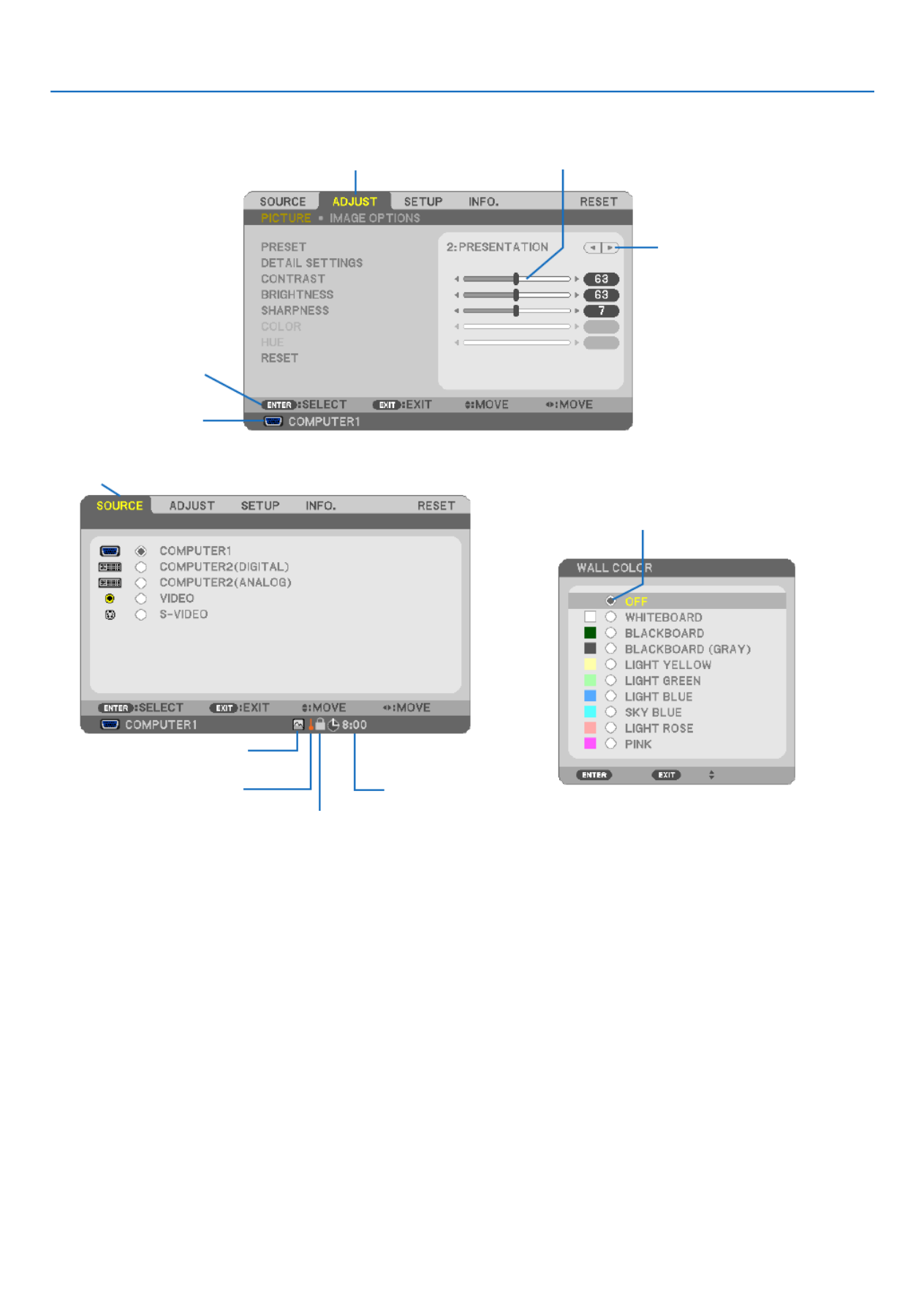
57
5. Using On-Screen Menu
Menu Elements
Slide bar
Solid triangle
Tab
Radio button
High Altitude symbol
Menuwindowsordialogboxestypicallyhavethefollowingelements:
Highlight .............................Indicates the selected menu or item.
Solid triangle ......................Indicates further choices are available. A highlighted triangle indicates the item is active.
Tab ......................................Indicates a group of features in a dialog box. Selecting on any tab brings its page to the front.
Radio button .......................Use this round button to select an option in a dialog box.
Source ................................Indicates the currently selected source.
Off Timer remaining time ....Indicates the remaining countdown time when the [OFF TIMER] is preset.
Slide bar .............................Indicates settings or the direction of adjustment.
Key Lock symbol ................Indicates the [CONTROL PANEL LOCK] is enabled.
Thermometer symbol .........Indicates the [ECO MODE] is forcibly set to [ON] mode because the internal temperature is too
high.
High Altitude symbol ..........Indicates the [FAN MODE] is set to [HIGH ALTITUDE] mode.
Source
Available buttons
Thermometer symbol
KeyLocksymbol
Off Timer remaining
time
Highlight

58
5. Using On-Screen Menu
List of Menu Items
Some menu items are not available depending on the input source.
MenuItem Default Options
SOURCE
COMPUTER1 *
COMPUTER2(DIGITAL)*1*
COMPUTER2(ANALOG)*1*
VIDEO *
S-VIDEO *
ADJUST
PICTURE
PRESET * 1–6
DETAIL
SETTINGS
GENERAL
REFERENCE *HIGH-BRIGHT,PRESENTATION,VIDEO,MOVIE,
GRAPHIC,sRGB
GAMMA
CORRECTION DYNAMIC,NATURAL,BLACKDETAIL
COLOR
TEMPERATURE * 5000, 6500, 7800, 8500, 9300, 10500
DYNAMIC
CONTRAST*2*OFF,ON
IMAGEMODE STILL,MOVIE*
WHITE
BALANCE
CONTRASTR 0
CONTRASTG 0
CONTRASTB 0
BRIGHTNESS
R0
BRIGHTNESS
G0
BRIGHTNESS
B0
CONTRAST
BRIGHTNESS
SHARPNESS
COLOR
HUE
RESET
IMAGE
OPTIONS
CLOCK *
PHASE *
HORIZONTAL *
VERTICAL *
OVERSCAN *0[%],5[%],10[%]
ASPECTRATIO
*NP610/NP510/NP410/NP405/NP310/NP305/NP610S:
AUTO,4:3,16:9,15:9,16:10,WIDEZOOM,NATIVE
*NP510W/NP410W/NP510WS:AUTO,4:3,16:9,15:9,
16:10,LETTERBOX,NATIVE
POSITION (NotavailableonNP510W/NP410W/NP510WS)0
SETUP
GENERAL
DIGITALZOOM*3100 80–100
AUTOKEYSTONE OFF OFF,ON
KEYSTONE 0
KEYSTONESAVE OFF OFF,ON
WALLCOLOR OFF
OFF,WHITEBOARD,BLACKBOARD,BLACKBOARD
(GRAY),LIGHTYELLOW,LIGHTGREEN,LIGHT
BLUE,SKYBLUE,LIGHTROSE,PINK
ECOMODE OFF OFF,ON
CLOSEDCAPTION OFF OFF,CAPTION1,CAPTION2,CAPTION3,CAPTION4,
TEXT1,TEXT2,TEXT3,TEXT4
LANGUAGE ENGLISH
ENGLISH,DEUTSCH,FRANÇAIS,ITALIANO,
ESPAÑOL,SVENSKA,日本語
DANSK,PORTUGUÊS, , MAGYAR,POLSKI,ČEŠTINA
NEDERLANDS,SUOMI
NORSK,TÜRKÇE,РУССКИЙ, Ελληνικά, , 中文, 한
국어
MENU
COLORSELECT COLOR COLOR,MONOCHROME
SOURCEDISPLAY ON OFF,ON
IDDISPLAY ON OFF,ON
ECOMESSAGE OFF OFF,ON
DISPLAYTIME AUTO45SEC MANUAL,AUTO5SEC,AUTO15SEC,AUTO45SEC
BACKGROUND BLUE BLUE,BLACK,LOGO
FILTERMESSAGE 500[H] OFF,100[H],200[H],500[H],1000[H]
* Theasterisk(*)indicatesthatthedefaultsettingvariesdependingonthesignal.
*1: COMPUTER2(DIGITAL)isnotavailableonNP405andNP305.Thesourceforthecomputer2analogsignalisdisplayedas“COMPUTER2”on
NP405 and NP305.
*2: DYNAMICCONTRASTisavailableonNP410andNP310only.
*3: DIGITALZOOMisavailableonNP610SandNP510WSonly.
*4: WiredLANisnotsupportedbyNP405andNP305.

59
5. Using On-Screen Menu
SETUP
INSTALLATION
ORIENTATION DESKTOP
FRONT
DESKTOPFRONT,CEILINGREAR,DESKTOPREAR,
CEILINGFRONT
CONTROLPANELLOCK OFF OFF,ON
SECURITY OFF OFF,ON
COMMUNICATIONSPEED 19200bps 4800bps, 9600bps, 19200bps
CONTROLID
CONTROLID
NUMBER 1 1–254
CONTROLID OFF OFF,ON
OPTIONS(1)
AUTOADJUST NORMAL OFF,NORMAL,FINE
FANMODE AUTO AUTO,HIGH,HIGHALTITUDE
SIGNAL
SELECT
COMPUTER1 RGB/
COMPONENT RGB/COMPONENT,RGB,COMPONENT
COMPUTER2
(ANALOG)*1
RGB/
COMPONENT RGB/COMPONENT,RGB,COMPONENT
VIDEO AUTO AUTO,NTSC3.58,NTSC4.43,PAL,PAL-M,PAL-N,
PAL60,SECAM
S-VIDEO AUTO AUTO,NTSC3.58,NTSC4.43,PAL,PAL-M,PAL-N,
PAL60,SECAM
WXGAMODE
NP610/NP510/
NP410/NP405/
NP310/NP305/
NP610S:OFF
NP510W/
NP410W/
NP510WS:ON
OFF,ON
DEINTERLACE ON OFF,ON
BEEP ON OFF,ON
OPTIONS(2)
OFFTIMER OFF OFF,0:30,1:00,2:00,4:00,8:00,12:00,16:00
STANDBYMODE NORMAL NORMAL,POWER-SAVING
AUTOPOWERON(AC) OFF OFF,ON
AUTOPOWERON(COMP1) OFF OFF,ON
AUTOPOWEROFF OFF OFF,0:05,0:10,0:20,0:30
DEFAULTSOURCESELECT LAST LAST,AUTO,COMPUTER1,COMPUTER2(DIGITAL)*1,
COMPUTER2(ANALOG),VIDEO,S-VIDEO
INFO.
USAGETIME
LAMPLIFEREMAINING
LAMPHOURSUSED
FILTERHOURSUSED
TOTALCARBONSAVINGS
SOURCE
SOURCENAME
SOURCEINDEX
HORIZONTALFREQUENCY
VERTICALFREQUENCY
SIGNALTYPE
VIDEOTYPE
SYNCTYPE
SYNCPOLARITY
SCANTYPE
WIREDLAN*4
PROJECTORNAME
IPADDRESS
SUBNETMASK
GATEWAY
MACADDRESS
VERSION
PRODUCT
SERIALNUMBER
FIRMWARE
DATA
CONTROLID(when[CONTROL
ID]isset)
RESET
CURRENTSIGNAL
ALLDATA
NETWORKSETTINGS*4
CLEARLAMPHOURS
CLEARFILTERHOURS
* Theasterisk(*)indicatesthatthedefaultsettingvariesdependingonthesignal.
*1: COMPUTER2(DIGITAL)isnotavailableonNP405andNP305.Thesourceforthecomputer2analogsignalisdisplayedas“COMPUTER2”on
NP405 and NP305.
*2: DYNAMICCONTRASTisavailableonNP410andNP310only.
*3: DIGITALZOOMisavailableonNP610SandNP510WSonly.
*4: WiredLANisnotsupportedbyNP405andNP305.
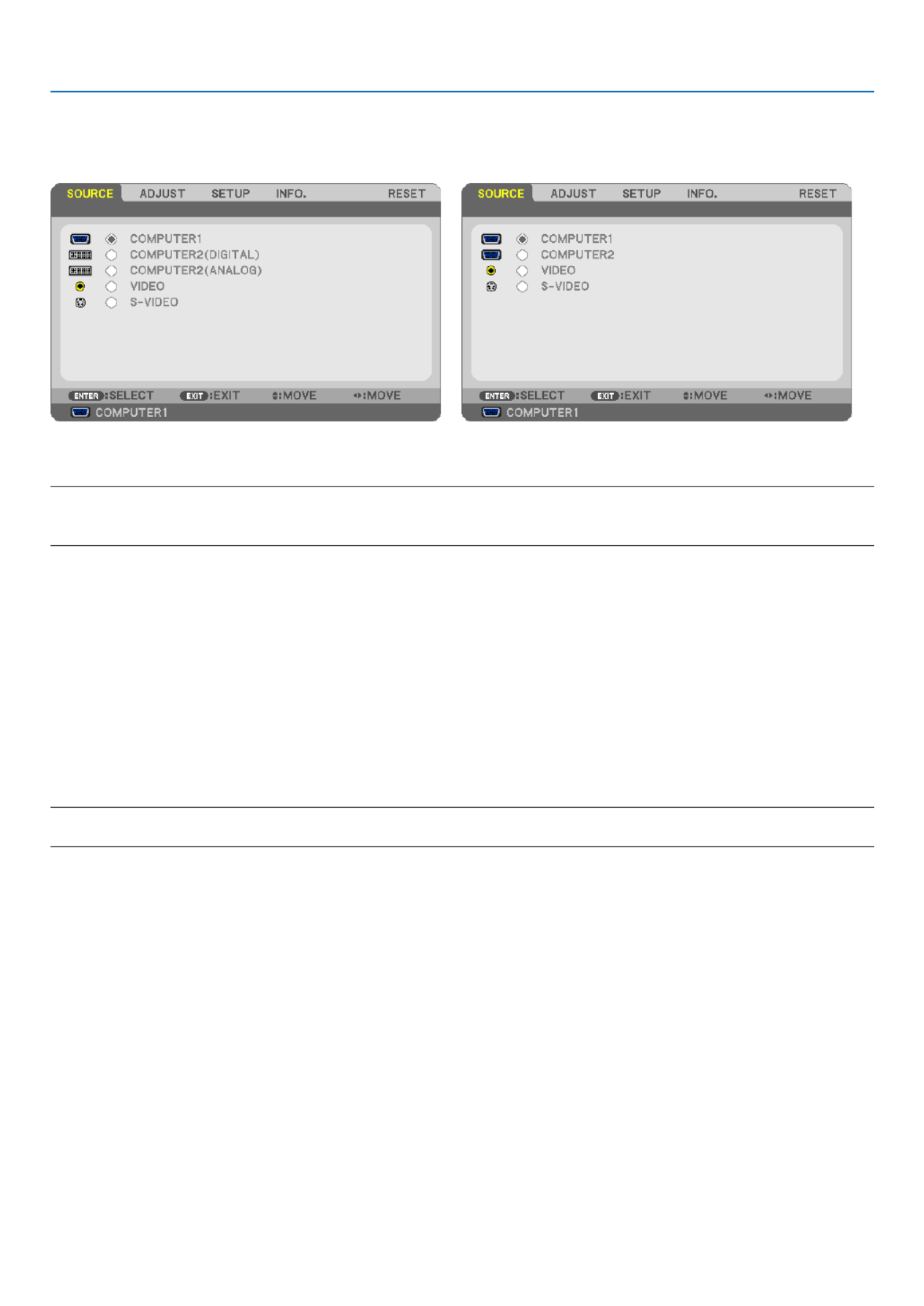
60
5. Using On-Screen Menu
Menu Descriptions & Functions [SOURCE]
[NP610/NP510/NP410/NP310/NP510W/NP410W/
NP610S/NP510WS] [NP405/NP305]
COMPUTER1
SelectsthecomputerconnectedtoyourCOMPUTER1INinputconnector.
NOTE:
• WhenthecomponentinputsignalisconnectedtotheCOMPUTER1INconnector,select[COMPUTER1].
• TheprojectorwilldetermineiftheinputsignalisRGBorcomponentsignal.
COMPUTER2(DIGITAL&ANALOG)
SelectsthecomputerconnectedtoyourCOMPUTER2IN(DVI-I)connector.
COMPUTER2(NP405andNP305only)
SelectsthecomputerconnectedtoyourCOMPUTER2INconnector.
VIDEO
SelectswhatisconnectedtoyourVIDEOinput-VCR,DVDplayerordocumentcamera.
S-VIDEO
SelectswhatisconnectedtoyourS-VIDEOinput-VCRorDVDplayer.
NOTE:Aframemayfreezeforabriefperiodoftimewhenavideoisplayedbackinfast-forwardorfast-rewindwithaVideoorS-
Video source.

61
5. Using On-Screen Menu
Menu Descriptions & Functions [ADJUST]
[PICTURE]
[PRESET]
Thisfunctionallowsyoutoselectoptimizedsettingsforyourprojectedimage.
Youcanadjustneutraltintforyellow,cyanormagenta.
Therearesixfactorypresetsoptimizedforvarioustypesofimages.Youcanalsouse[DETAILSETTINGS]tosetuser
adjustablesettingstocustomizeeachgammaorcolor.
Yoursettingscanbestoredin[PRESET1]to[PRESET6].
HIGH-BRIGHT ........ Recommended for use in a brightly lit room.
PRESENTATION ..... Recommended for making a presentation using a PowerPoint file.
VIDEO .................... Recommended for typical TV program viewing.
MOVIE ................... Recommended for movies.
GRAPHIC ............... Recommended for graphics.
sRGB ..................... Standard color values
[DETAIL SETTINGS]
[NP610/NP510/NP405/NP305/NP510W/NP410W/
NP610S/NP510WS] [NP410/NP310]

62
5. Using On-Screen Menu
[GENERAL]
StoringYourCustomizedSettings[REFERENCE]
Thisfunctionallowsyoutostoreyourcustomizedsettingsin[PRESET1]to[PRESET6].
First,selectabasepresetmodefrom[REFERENCE],thenset[GAMMACORRECTION]and[COLORTEMPERA-
TURE].
HIGH-BRIGHT ........ Recommended for use in a brightly lit room.
PRESENTATION ..... Recommended for making a presentation using a PowerPoint file.
VIDEO .................... Recommended for typical TV program viewing.
MOVIE ................... Recommended for movies.
GRAPHIC ............... Recommended for graphics.
sRGB ..................... Standard color values.
SelectingGammaCorrectionMode[GAMMACORRECTION]
Eachmodeisrecommendedfor:
DYNAMIC .............. Creates a high-contrast picture.
NATURAL ............... Natural reproduction of the picture.
BLACK DETAIL ....... Emphasizes detail in dark areas of the picture.
AdjustingColorTemperature[COLORTEMPERATURE]
Thisoptionallowsyoutoselectthecolortemperatureofyourchoice.
NOTE:When[PRESENTATION]or[HIGH-BRIGHT]isselectedin[REFERENCE],thisfunctionisnotavailable.
AdjustingBrightnessandContrast[DYNAMICCONTRAST](NP410andNP310)
Thisfunctionallowsyoutoadjustthecontrastratioopticallyusingthebuilt-iniris.
Toincreasethecontrastratio,select[ON].
SelectingStillImageModeorMovieMode[IMAGEMODE]
Thisfunctionallowsyoutoselectthestillimagemodeorthemoviemode.
STILL ..................... This mode is for a still image.
MOVIE ................... This mode is for a movie.
NOTE:Thisfunctionisavailableonlywhen[HIGH-BRIGHT]isselectedfor[REFERENCE].
AdjustingWhiteBalance[WHITEBALANCE]
Thisallowsyoutoadjustthewhitebalance.Contrastforeachcolor(RGB)toadjustthewhitelevelofthescreen;
Brightnessforeachcolor(RGB)isusedtoadjusttheblacklevelofthescreen.
[CONTRAST]
Adjusts the intensity of the image according to the incoming signal.
[BRIGHTNESS]
Adjuststhebrightnesslevelorthebackrasterintensity.
[SHARPNESS]
Controlsthedetailoftheimage.
[COLOR]
Increasesordecreasesthecolorsaturationlevel.

63
5. Using On-Screen Menu
[HUE]
Variesthecolorlevelfrom+/−greento+/−blue.Theredlevelisusedasreference.
Inputsignal CONTRAST BRIGHTNESS SHARPNESS COLOR HUE
Computer(RGBDIGITAL) Yes Yes Yes No No
Computer(RGBANALOG) Yes Yes Yes No No
Component Yes Yes Yes Yes* Yes*
Video,S-Video Yes Yes Yes Yes Yes
Yes=Adjustable,No=Notadjustable,Yes*=dependingonthesignal
NOTE:TheNP405andNP305donotsupport“Computer(RGBDIGITAL)”signal.
[RESET]
Thesettingsandadjustmentsfor[CONTRAST],[BRIGHTNESS],[SHARPNESS],[COLOR],[HUE],and[REFER-
ENCE]within[PRESET]willbereturnedtothefactorysettings.
Thesettingsandadjustmentsunder[DETAILSETTINGS]withinthe[PRESET]screenthatarenotcurrentlyselected
willnotbereset.

64
5. Using On-Screen Menu
[IMAGE OPTIONS]
AdjustingClockandPhase[CLOCK/PHASE]
ThisallowsyoutomanuallyadjustCLOCKandPHASE.
CLOCK ................... Use this item to fine tune the computer image or to remove any vertical banding that might appear. This
function adjusts the clock frequencies that eliminate the horizontal banding in the image.
This adjustment may be necessary when you connect your computer for the first time.
PHASE ................... Use this item to adjust the clock phase or to reduce video noise, dot interference or cross talk. (This is
evident when part of your image appears to be shimmering.)
Use [PHASE] only after the [CLOCK] is complete.

65
5. Using On-Screen Menu
AdjustingHorizontal/VerticalPosition[HORIZONTAL/VERTICAL]
Adjuststheimagelocationhorizontallyandvertically.
- Animagecanbedistortedduringtheadjustmentof[CLOCK]and[PHASE].Thisisnotmalfunction.
- Theadjustmentsfor[CLOCK], [PHASE],[HORIZONTAL],and [VERTICAL]willbe storedinmemory forthe
currentsignal.Thenexttimeyouprojectthesignalwiththesameresolution,horizontalandverticalfrequency,
itsadjustmentswillbecalledupandapplied.
Todeleteadjustmentsstoredinmemory,fromthemenu,youselect[RESET] [CURRENTSIGNAL]or[ALL→
DATA]andresettheadjustments.
SelectingOverscanPercentage[OVERSCAN]
Selectoverscanpercentage(0%,5%and10%)forsignal.
Projected image
Overscaned by 10%
NOTE:
• The[0[%]]cannotbeselectedwhenVIDEOandS-VIDEOsignalsareused.
• [OVERSCAN]isnotavailablewhen[NATIVE]isselectedfor[ASPECTRATIO].

66
5. Using On-Screen Menu
SelectingAspectRatio[ASPECTRATIO]
Theterm“aspectratio”referstotheratioofwidthtoheightofaprojectedimage.
The projector automatically determines the incoming signal and displays it in its appropriate aspect ratio.
•Thistableshowstypicalresolutionsandaspectratiosthatmostcomputerssupport.
Resolution AspectRatio
VGA 4:3 640 x 480
SVGA 800 x 600 4:3
XGA 1024 x 768 4:3
WXGA 1280 x 768 15:9
WXGA 1280 x 800 16:10
WXGA+ 1440 x 900 16:10
SXGA 1280 x 1024 5:4
SXGA+ 1400 x 1050 4:3
UXGA 1600 x 1200 4:3
Options Function
AUTO Theprojectorwillautomaticallydeterminetheincomingsignalanddisplayitinitsaspect
ratio. ( →next page)
Theprojectormayerroneouslydeterminetheaspectratiodependingonitssignal.Ifthis
occurs,selecttheappropriateaspectratiofromthefollowing.
4:3 Theimageisdisplayedin4:3aspectratio.
16:9 Theimageisdisplayedin16:9aspectratio.
15:9 Theimageisdisplayedin15:9aspectratio.
16:10 Theimageisdisplayedin16:10aspectratio.
WIDEZOOM
(NP610/NP510/NP410/
NP405/NP310/NP305/
NP610S)
The image is stretched left and right.
Parts of the displayed image are cropped at the left and right edges and therefore not
visible.
LETTERBOX
(NP510W/NP410W/
NP510WS)
Theimageofaletterboxsignalisstretchedequallyinthehorizontalandverticaldirections
to fit the screen. Parts of the displayed image are cropped at the top and bottom edges
and therefore not visible.
NATIVE Theprojectordisplaysthecurrentimageinitstrueresolutionwhentheincomingcomputer
signalhasalowerresolutionthantheprojector’snativeresolution.
[Example 1] When the incoming
signalwiththeresolutionof800x600
is displayed on the NP610/NP510/
N P 4 1 0 / NP 4 0 5 / N P 3 1 0 / NP 3 0 5 /
NP610S:
[Example2] When the incoming sig-
nalwiththeresolutionof800x600is
displayedontheNP510W/NP410W/
NP510WS:
NOTE:
• Whenanon-computersignalisdisplayed,the[NATIVE]isnotavailable.
• Whenasignalwithahigherresolutionthantheprojector’snativeresolutionisdisplayed,[NATIVE]
is not available.
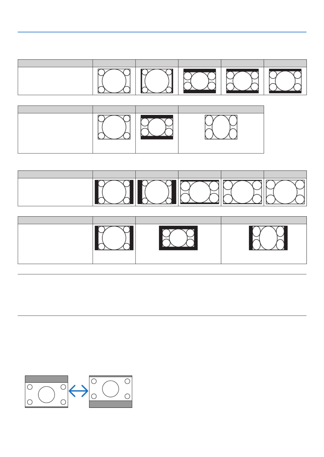
67
5. Using On-Screen Menu
Sampleimagewhentheappropriateaspectratioisautomaticallydetermined
NP610/NP510/NP410/NP405/NP310/NP305/NP610S
[Computersignal]
Aspect ratio of incoming signal 4:3 5:4 16:9 15:9 16:10
Sampleimagewhentheappro-
priate aspect ratio is automati-
cally determined
[Videosignal]
Aspect ratio of incoming signal 4:3 Letterbox Squeeze
Sample image when the as-
pect ratio is automatically de-
termined NOTE:Todisplayasqueezedsignalprop-
erly,select[16:9]or[WIDEZOOM].
NP510W/NP410W/NP510WS
[Computersignal]
Aspect ratio of incoming signal 4:3 5:4 16:9 15:9 16:10
Sampleimagewhentheappro-
priate aspect ratio is automati-
cally determined
[Videosignal]
Aspect ratio of incoming signal 4:3 Letterbox Squeeze
Sample image when the as-
pect ratio is automatically de-
termined NOTE:Todisplayaletterboxsignalprop-
erly,select[LETTERBOX].
NOTE:Todisplayasqueezedsignalprop-
erly,select[16:9].
TIP:
• Imagepositioncanbeadjustedverticallyusing[POSITION]whenthe[16:9],[15:9],or[16:10]aspectratiosareselected.
• Theterm“letterbox”referstoamorelandscape-orientedimagewhencomparedtoa4:3image,whichisthestandardaspect
ratio for a vide source.
Theletterboxsignalhasaspectratioswiththevistasize“1.85:1”orcinemascopesize“2.35:1”formovielm.
• Theterm“squeeze”referstothecompressedimageofwhichaspectratioisconvertedfrom16:9to4:3.
Adjusting theVertical Position of Image [POSITION] (not available on NP510W/NP410W/
NP510WS)
(onlywhen[16:9],[15:9],or[16:10]isselectedfor[ASPECTRATIO])
When[16:9],[15:9],or[16:10]isselectedin[ASPECTRATIO],theimageisdisplayedwithblackbordersonthetop
and bottom.
Youcanadjusttheverticalpositionfromthetoptothebottomoftheblackarea.
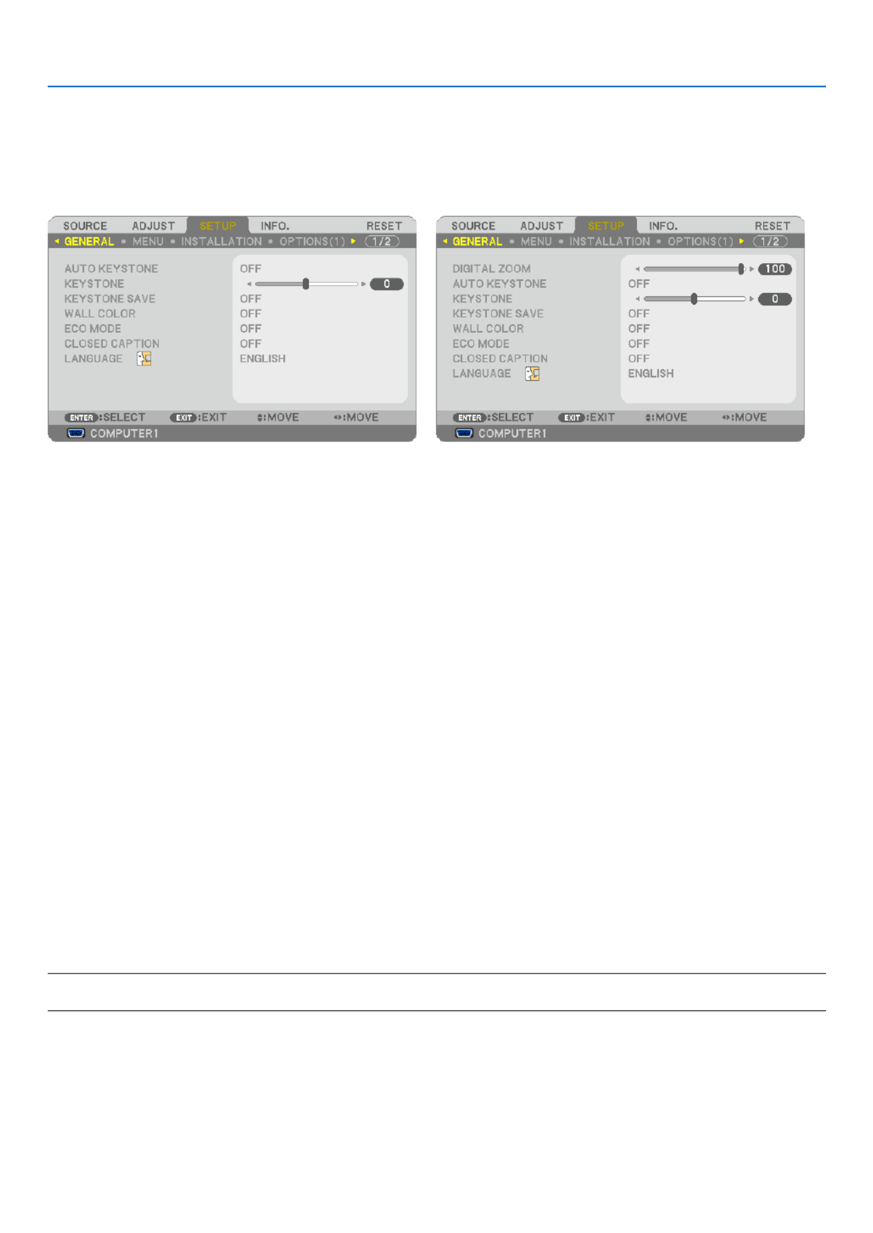
68
5. Using On-Screen Menu
Menu Descriptions & Functions [SETUP]
[GENERAL]
[NP610/NP510/NP410/NP405/NP310/NP305/NP510W/
NP410W] [NP610S/NP510WS]
UsingDigitalZoom[DIGITALZOOM](NP610S/NP510WS)
Thisfeatureallowsyoutoelectronicallyneadjusttheimagesizeonthescreen.
Use or button to large or reduce the projected image.
TIP:
Toadjusttheprojectedimagesizeroughly,movetheprojectorawayorclosertothescreen.(→ page 30).Toneadjustthezoom,
usethe[DIGITALZOOM]function.
EnablingAutoKeystone[AUTOKEYSTONE]
Thisfeatureallowstheprojectortodetectitstiltandcorrectverticaldistortionautomatically.
ToturnontheAUTOKEYSTONEfeature,select[ON].ToadjusttheKEYSTONEfeaturemanually,select[OFF].
CorrectingVerticalKeystoneDistortionManually[KEYSTONE]
Youcancorrectverticaldistortionmanually.(→ page )34
TIP: When this option is highlighted, pressing the ENTER button will display its slide bar for adjustment.
SavingVerticalKeystoneCorrection[KEYSTONESAVE]
Thisoptionenablesyoutosaveyourcurrentkeystonesettings.
OFF ........................ Does not save current keystone correction settings. It will return your keystone correction settings to
“zero”.
ON ......................... Saves current keystone correction settings
Savingyourchangeonceaffectsallsources.Thechangesaresavedwhentheprojectoristurnedoff.
NOTE:When[AUTOKEYSTONE]issetto[ON],[KEYSTONESAVE]isnotavailable.Nexttimeyouturnonthepower,the
KEYSTONEfunctionwillworkandthedatastoredwith[KEYSTONESAVE]willbeinvalid.
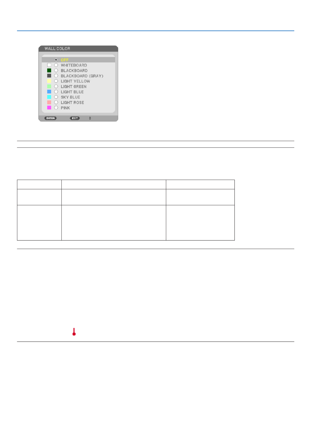
69
5. Using On-Screen Menu
UsingtheWallColorCorrection[WALLCOLOR]
Thisfunctionallowsforquickadaptivecolorcorrectioninapplicationswherethescreenmaterialisnotwhite.
NOTE:Selecting[WHITEBOARD]reduceslampbrightness.
SettingEcoMode[ECOMODE]
ThisfeatureturnsonorofftheECOmode.Thelamplifecanbeextendedbyselecting[ON].Selecting[ON]also
decreasesfannoisewhencomparedto[OFF]mode.
ECOMODE Description StatusofLAMPindicator
OFF ThisistheDefaultsetting
(100%Brightness). Off
ON
Select this mode to increase the lamp
life (approx. 70% Brightness on NP610/
NP510W/NP410W/NP610S/NP510WS
and approx. 80% Brightness on NP510/
NP410/NP405/NP310/NP305).
Steady Green light
NOTE:
• The[LAMPLIFEREMAINING]and[LAMPHOURSUSED]canbecheckedin[USAGETIME].Select[INFO.] [USAG→
(→ page 78)
• Theprojectorisalwaysin[ON]for90secondsafterthelampisturnedonandwhilethePOWERindicatorisblinkinggreen.T
lampconditionwillnotbeaffectedevenwhen[ECOMODE]ischanged.
• Ifthereisnosignalforaboutoneminute,theprojectorwilldisplayablue,blackorlogobackground(dependingonsetting)an
gointo[ON].
Theprojectorwillreturntothe[OFF]modeonceasignalisaccepted.
• Iftheprojectorbecomesoverheatedin[OFF]modebecauseofuseinahigh-temperatureroom,theremaybeacasewherethe
[ECOMODE]automaticallychangesto[ON]modetoprotecttheprojector.Thismodeiscalled“forcedECOmode”.Whent
projectorisin[ON]mode,thepicturebrightnessdecreases.TheLAMPindicator’ssteadylightindicatestheprojectorisin[ON
mode.Whentheprojectorcomesbacktonormaltemperature,the[ECOMODE]returnsto[OFF]mode.
Thermometer symbol [ ]indicatesthe[ECOMODE]isautomaticallysetto[ON]modebecausetheinternaltemperatureistoo
high.

70
5. Using On-Screen Menu
SettingClosedCaption[CLOSEDCAPTION]
ThisoptionsetsseveralclosedcaptionmodesthatallowtexttobesuperimposedontheprojectedimageofVideo
orS-Video.
OFF ........................ This exits the closed caption mode.
CAPTION 1-4 ......... Text is superimposed.
TEXT 1-4 ................ Text is displayed.
NOTE:
• Theclosedcaptionisnotavailableunderthefollowingconditions:
- when messages or menus are displayed.
- whenanimageismagnied,frozen,ormuted.
• Doingthefollowingmaycauseportionsofsuperimposedtextorclosedcaptiontobetruncated.
Ifthisoccurs,trytochangecorrectionamountorselectiontoplacethesuperimposedtextorclosedcaptionwithinthe
screen.
- Usingthe[DIGITALZOOM]or[KEYSTONE]functiontocorrecttheimageexcessively
- Selecting[16:10]or[16:9]from[ASPECTRATIO]
- Usingthe[POSITION](notavailableonNP510W/NP410W/NP510WS)
SelectingMenuLanguage[LANGUAGE]
Youcanchooseoneof21languagesforon-screeninstructions.
NOTE:Yoursettingwillnotbeaffectedevenwhen[RESET]isdonefromthemenu.
[MENU]
SelectingMenuColor[COLORSELECT]
Youcanchoosebetweentwooptionsformenucolor:COLORandMONOCHROME.
TurningOn/OffSourceDisplay[SOURCEDISPLAY]
ThisoptionturnsonoroffinputnamedisplaysuchasCOMPUTER1,COMPUTER2(DIGITAL),COMPUTER2(ANA-
LOG),VIDEO,S-VIDEOandNoInputtobedisplayedonthetoprightofthescreen.
OnNP405/NP305,theinputnamewillbedisplayedasCOMPUTER1,COMPUTER2,VIDEO,andS-VIDEO.
TurningON/OFFControlID[IDDISPLAY]
(AvailableonlywhentheoptionalremotecontrolNP02RCisused)
ID DISPLAY ........... This option turns on or off the ID number which is displayed when the ID SET button on the remote control
is pressed.

71
5. Using On-Screen Menu
TurningOn/OffEcoMessage[ECOMESSAGE]
Thisoptionturnsonoroffthefollowingmessageswhentheprojectoristurnedon.
TheEcoMessagepromptstheusertosaveenergy.When[OFF]isselectedfor[ECOMODE],youwillgetamessage
topromptyoutoselect[ON]for[ECOMODE].
When[ON]isselectedfor[ECOMODE]
Toclosethemessage,pressanyoneofthebuttons.Themessagewilldisappearifnobuttonoperationisdonefor
30 seconds.
When[OFF]isselectedfor[ECOMODE]
PressingtheENTERbuttonwilldisplaythe[ECOMODE]screen.(→ page )69
Toclosethemessage,presstheEXITbutton.
SelectingMenuDisplayTime[DISPLAYTIME]
Thisoptionallowsyoutoselecthowlongtheprojectorwaitsafterthelasttouchofabuttontoturnoffthemenu.The
presetchoicesare[MANUAL],[AUTO5SEC],[AUTO15SEC],and[AUTO45SEC].The[AUTO45SEC]isthefac-
tory preset.
SelectingaColororLogoforBackground[BACKGROUND]
Use this feature to display a blue/black screen or logo when no signal is available.The default background is
[BLUE].
NOTE:Yoursettingwillnotbeaffectedevenwhen[RESET]isdonefromthemenu.
SelectingIntervalTimeforFilterMessage[FILTERMESSAGE]
Thisoptionallowsyoutoselectthetimepreferencebetweendisplayingthemessageforcleaningthelters.Clean
thelterwhenyougetthemessage“PLEASECLEANFILTER.”(→ page )81
Fiveoptionsareavailable:OFF,100[H],200[H],500[H],1000[H]
Thedefaultsettingis500[H].
NOTE:Yoursettingwillnotbeaffectedevenwhen[RESET]isdonefromthemenu.
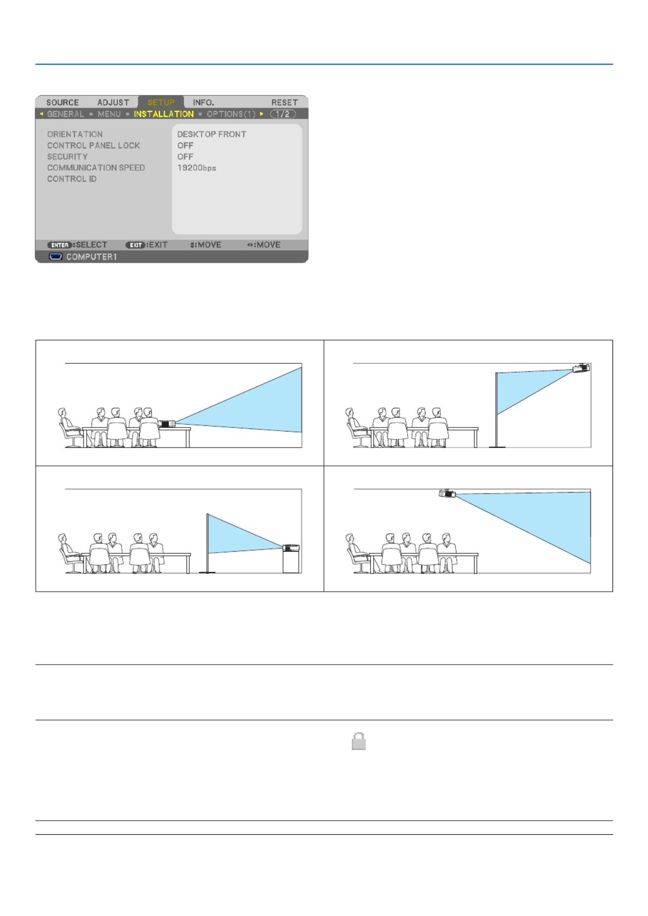
72
5. Using On-Screen Menu
[INSTALLATION]
SelectingProjectorOrientation[ORIENTATION]
Thisreorientsyourimageforyourtypeofprojection.Theoptionsare:desktopfrontprojection,ceilingrearprojection,
desktoprearprojection,andceilingfrontprojection.
DESKTOPFRONT CEILINGREAR
DESKTOPREAR CEILINGFRONT
DisablingtheCabinetButtons[CONTROLPANELLOCK]
ThisoptionturnsonorofftheCONTROLPANELLOCKfunction.
NOTE:
• ThisCONTROLPANELLOCKdoesnotaffecttheremotecontrolfunctions.
• Whenthecontrolpanelislocked,pressingandholdingtheEXITbuttonontheprojectorcabinetforabout10secondswillchang
thesettingto[OFF].
TIP:Whenthe[CONTROLPANELLOCK]isturnedon,akeylockicon[ ]willbedisplayedatthebottomrightofthemen
EnablingSecurity[SECURITY]
ThisfeatureturnsonorofftheSECURITYfunction.
Unlessthecorrectkeywordisentered,theprojectorcannotprojectanimage.(→ page )43
NOTE:Yoursettingwillnotbeaffectedevenwhen[RESET]isdonefromthemenu.

73
5. Using On-Screen Menu
SelectingCommunicationSpeed[COMMUNICATIONSPEED]
ThisfeaturesetsthebaudrateofthePCControlport(D-Sub9P).Itsupportsdataratesfrom4800to19200bps.The
defaultis19200bps.Selecttheappropriatebaudrateforyourequipmenttobeconnected(dependingontheequip-
ment,alowerbaudratemayberecommendedforlongcableruns).
NOTE:Yourselectedcommunicationspeedwillnotbeaffectedevenwhen[RESET]isdonefromthemenu.
SettingIDtotheProjector[CONTROLID]
(AvailableonlywhentheoptionalremotecontrolNP02RCisused)
YoucanoperatemultipleprojectorsseparatelyandindependentlywiththesingleremotecontrolthathastheCONTROL
IDfunction.IfyouassignthesameIDtoalltheprojectors,youcanconvenientlyoperatealltheprojectorstogether
usingthesingleremotecontrol.Todoso,youhavetoassignanIDnumbertoeachprojector.
CONTROL ID NUMBER .......Select a number from 1 to 254 you wish to assign to your projector.
CONTROL ID .......................Select [OFF] to turn off the CONTROL ID setting and select [ON] to turn on the CONTROL ID set-
ting.
NOTE:
• Selecting[ON]for[CONTROLID]willmaketheremotecontrolsuppliedwiththeprojectorinoperable.Thebuttonsontheprojec
cabinetcanbeused.NeithercanyouoperatetheprojectorbyusingtheoptionalremotecontrolNP01RCthatdoesnothasthe
CONTROLIDfunction.
• Yoursettingwillnotbeaffectedevenwhen[RESET]isdonefromthemenu.
•PressingandholdingtheENTERbuttonontheprojectorcabinetfor10secondswilldisplaythemenuforcancelingtheContro
ID.
AssigningorChangingtheControlID
1. Turn on the projector.
2. Press the ID SET button on the remote control (NP02RC).
The CONTROL ID screen will be displayed.
If the projector can be operated with the current remote control ID, the [ACTIVE] will be displayed. If the projector
cannot be operated with the current remote control ID, the [INACTIVE] will be displayed. To operate the inactive
projector, assign the control ID used for the projector by using the following procedure (Step 3).
3. Press one of numeric keypad buttons while pressing and holding the ID SET button on the remote control
(NP02RC).
Example:
To assign “3”, press the “3” button on the remote control.
No ID means that all the projectors can be operated together with a single remote
control. To set “No ID”, enter “000” or press the CLEAR button.
TIP:TherangeofIDsisfrom1to254.
4. Release the ID SET button.
The updated CONTROL ID screen will be displayed.
NOTE:TheIDscanbeclearedinafewdaysafterthebatteriesarerundownorremoved.
MAGNIFYVOLUME
PICTURE LAMP MODE ASPECT
AV-MUTE 3D REFORM FREEZE
ID SET
LENS SHIFT
FOCUS
/ZOOM HELP
PAGE
L-CLICK R-CLICK
UP
DOWN
ID
MAGNIFY
VOLUME
PICTURE LAMP MODE ASPECT
AV-MUTE 3D REFORM FREEZE
ID SET
LENS SHIFT
FOCUS
/ZOOM HELP
PAGE
MENU
L-CLICK R-CLICK
EXIT
ENTER
UP
DOWN
ID
ID
1 32
4 65
7 98
0
CLEAR

74
5. Using On-Screen Menu
[OPTIONS(1)]
SettingAutoAdjust[AUTOADJUST]
This feature sets the Auto Adjust mode so that the computer signal can be automatically or manually adjusted for
noiseandstability.Youcanautomaticallymakeadjustmentintwoways:[NORMAL]and[FINE].
OFF ........................ The computer signal will not be automatically adjusted. You can manually optimize the computer signal.
NORMAL ................ Default setting. The computer signal will be automatically adjusted. Normally select this option.
FINE ....................... Select this option if ne adjustment is needed. It takes more time to switch to the source than when [NOR-
MAL]is selected.
SelectingFanMode[FANMODE]
Thisoptionallowsyoutoselectthreemodesforfanspeed:Automode,Highspeedmode,andHighAltitudemode.
AUTO ..................... The built-in fans automatically run at a variable speed according to the internal temperature.
HIGH ...................... The built-in fans run at high speed.
HIGH ALTITUDE ..... The built-in fans run at a high speed. Select this option when using the projector at altitudes approximately
5500 feet/1600 meters or higher.
Whenyouwishtocooldownthetemperatureinsidetheprojectorquickly,select[HIGH].
NOTE:
• ItisrecommendedthatyouselectHighspeedmodeifyouusetheprojectornon-stopforconsecutivedays.
•Set[FANMODE]to[HIGHALTITUDE]whenusingtheprojectorataltitudesapproximately5500feet/1600metersorhigher.
• Usingtheprojectorataltitudesapproximately5500feet/1600metersorhigherwithoutsettingto[HIGHALTITUDE]cancaus
the projector to overheat and the protector could shut down. If this happens, wait a couple minutes and turn on the projector.
•Usingtheprojectorataltitudeslessthanapproximately5500feet/1600metersandsettingto[HIGHALTITUDE]cancauseth
lamptoovercool,causingtheimagetoicker.Switch[FANMODE]to[AUTO].
•Usingtheprojectorataltitudesapproximately5500feet/1600metersorhighercanshortenthelifeofopticalcomponentssuch
as the lamp.
• Yoursettingwillnotbeaffectedevenwhen[RESET]isdonefromthemenu.

75
5. Using On-Screen Menu
SelectingSignalFormat[SIGNALSELECT]
[COMPUTER1],[COMPUTER2(ANALOG)],[COMPUTER2onNP405/NP305]
Allows youto choose [COMPUTER1],or [COMPUTER2(ANALOG)] foranRGB sourcesuch asa computer,or
[COMPONENT]foracomponentvideosourcesuchasaDVDplayer.Normallyselect[RGB/COMPONENT]andthe
projectorautomaticallydetectsacomponentsignal.Howevertheremaybesomecomponentsignalsthattheprojector
isunabletodetect.Ifthisisthecase,select[COMPONENT].
[VIDEO&S-VIDEOSystemSelect]
This feature enables you to select composite video standards automatically or manually.
Normallyselect[AUTO]andtheprojectorwillautomaticallydetectthevideostandard.
Inthecasewheretheprojectorhasdifcultydetectingthevideostandard,selecttheappropriatevideostandardfrom
the menu.
ThismustbedoneforVIDEOandS-VIDEOrespectively.
EnablingorDisablingWXGAMode[WXGAMODE]
Selecting[ON]willgiveprioritytoaWXGA(1280x768)signalinrecognizinganinputsignal.
When[WXGAMODE]issetto[ON],anXGA(1024x768)signalmaynotberecognizedonNP610,NP510,NP410,
NP405,NP310,NP305,orNP610S.Inthiscase,select[OFF].
Enablingthedeinterlace[DEINTERLACE]
Turns on or off the deinterlace function for a telecine signal.
OFF ........................ Select this option if there is any jitter or artifacts in video.
ON ......................... Default standard setting.
NOTE:ThisfeatureisnotavailableforRGB,480p,576pandHDTVsignals.
EnablingKeySoundandErrorSound[BEEP]
Thisfeatureturnsonoroffthebuttonsoundoralarmwhenthefollowingoperationsareperformed.
-Displayingthemainmenu
-Switchingsources
-Resettingdatabyusing[RESET]
-PressingPOWERONorPOWEROFFbutton

76
5. Using On-Screen Menu
[OPTIONS(2)]
UsingOffTimer[OFFTIMER]
1. Select your desired time between 30 minutes and 16 hours: OFF, 0:30, 1:00, 2:00, 4:00, 8:00, 12:00, 16:00.
2. Press the ENTER button on the remote control.
3. The remaining time starts counting down.
4. The projector will turn off after the countdown is complete.
NOTE:
• Tocancelthepresettime,set[OFF]forthepresettimeorturnoffthepower.
• Whentheremainingtimereaches3minutesbeforetheprojectoristurnedoff,the[THEPROJECTORWILLTURNOFFWITH
MINUTES]messagewillbedisplayedonthebottomofthescreen.
SelectingPower-savingin[STANDBYMODE]
Theprojectorhastwostandbymodes:[NORMAL]and[POWER-SAVING].
ThePOWER-SAVINGmodeisthemodethatallowsyoutoputtheprojectorinthepower-savingconditionwhich
consumeslesspowerthantheNORMALmode.TheprojectorispresetforNORMALmodeatthefactory.
NORMAL ................ Power indicator: Orange light/STATUS indicator: Green light
POWER-SAVING .... Power indicator: Red light/STATUS indicator: Off
The following connectors, buttons or functions will not work during this mode.
- PC CONTROL port, MONITOR OUT connector, and AUDIO OUT connector
- LAN and Mail Alert functions
- Buttons other than POWER button on the cabinet
- Buttons other than POWER ON button on the remote control
- Virtual Remote function
NOTE:
• When[CONTROLPANELLOCK],[CONTROLID],or[AUTOPOWERON(COMP1)]isturnedon,the[STANDBYMODE]
not available.
• Yoursettingwillnotbeaffectedevenwhen[RESET]isdonefromthemenu.
EnablingAutoPowerOn[AUTOPOWERON(AC)]
Turnstheprojectoronautomaticallywhenthepowercableisinsertedintoanactivepoweroutlet.Thiseliminatesthe
needtoalwaysusethePOWERbuttonontheremotecontrolorprojectorcabinet.

77
5. Using On-Screen Menu
TurningOntheProjectorByApplyingComputerSignal[AUTOPOWERON(COMP1)]
WhentheprojectorisinStandbymode,applyingacomputersignalfromacomputerconnectedtotheCOMPUTER1
INinputwillpowerontheprojectorandsimultaneouslyprojectthecomputer’simage.
ThisfunctionalityeliminatestheneedtoalwaysusethePOWERbuttonontheremotecontrolortheprojectorcabinet
topowerontheprojector.
Tousethisfunction,rstconnectacomputertotheprojectorandtheprojectortoanactiveACinput.
NOTE:
• Disconnectingacomputersignalfromthecomputerwillnotpowerofftheprojector.Werecommendusingthisfunctionincom-
binationoftheAUTOPOWEROFFfunction.
• Thisfunctionwillnotbeavailableunderthefollowingconditions:
- whenacomponentsignalisappliedtotheCOMPUTER1INconnector
- whenaSynconGreenRGBsignalorcompositesyncsignalisapplied
• ToenabletheAUTOPOWERON(COMP1)afterturningofftheprojector,wait3secondsandinputacomputersignal.
Ifacomputersignalisstillpresentwhentheprojectoristurnedoff,theAUTOPOWERON(COMP1)willnotworkandtheproje
remains in standby mode.
EnablingPowerManagement[AUTOPOWEROFF]
Whenthisoptionisselectedyoucanenabletheprojectortoautomaticallyturnoff(attheselectedtime:5min.,10min.,
20min., 30min.) if there is no signal received by any input or if no operation is performed.
SelectingDefaultSource[DEFAULTSOURCESELECT]
Youcansettheprojectortodefaulttoanyoneofitsinputseachtimetheprojectoristurnedon.
LAST ...................................Sets the projector to default to the previous or last active input each time the projector is turned
on.
AUTO ..................................Searches for an active source in order of COMPUTER1 → COMPUTER 2(DIGITAL) → COMPUTER2
(ANALOG) VIDEO S-VIDEO COMPUTER1 and displays the rst found source.→ → →
COMPUTER1 ......................Displays the computer signal from the COMPUTER 1 IN connector every time the projector is turned
on.
COMPUTER2(DIGITAL) .......Displays the DVI digital from the COMPUTER 2 IN connector every time the projector is turned on.
(Not available on NP405/NP305)
COMPUTER2(ANALOG) ......Displays the computer signal from the COMPUTER 2 IN connector every time the projector is turned
on. (“COMPUTER2” on NP405/NP305)
VIDEO .................................Displays the Video source from the VIDEO IN connector every time the projector is turned on.
S-VIDEO .............................Displays the Video source from the S-VIDEO IN connector every time the projector is turned on.

78
5. Using On-Screen Menu
7 Menu Descriptions & Functions [INFO.]
Displaysthestatusofthecurrentsignalandlampusage.Thisitemhasfourpages(threepagesonNP405andNP305).
Theinformationincludedisasfollows:
TIP:PressingtheHELPbuttonontheremotecontrolwillshowthe[INFO.]menuitems.
[USAGE TIME]
[LAMPLIFEREMAINING](%)*
[LAMPHOURSUSED](H)
[FILTERHOURSUSED](H)
[TOTALCARBONSAVINGS](kg-CO2)
* Theprogressindicatorshowsthepercentageofremainingbulblife.
The value informs you of the amount of lamp usage. When the remaining lamp time reaches 0, the LAMPLIFE
REMAININGbarindicatorchangesfrom0%to100Hoursandstartscountingdown.
Iftheremaininglamptimereaches0hours,theprojectorwillnotturnonregardlessofwhethertheECOMODE
issettoOFForON.
• Themessagetotheeffectthatthelamportheltersshouldbereplacedwillbedisplayedforoneminutewhen
theprojectoristurnedonandwhenthePOWERbuttonontheprojectorortheremotecontrolispressed.
To dismiss this message, press any button on the projector or the remote control.
Lamplife(H)
Replacement lamp ModelECO MODE
OFF ON
4000 5000 NP07LP NP610/NP510W/NP410W/NP610S/NP510WS
NP14LP NP510/NP410/NP405/NP310/NP305
• [TOTALCARBONSAVINGS]
Thisdisplaystheestimatedcarbonsavinginformationinkg.Thecarbonfootprintfactorinthecarbonsavingcal-
culationisbasedontheOECD(2008Edition).
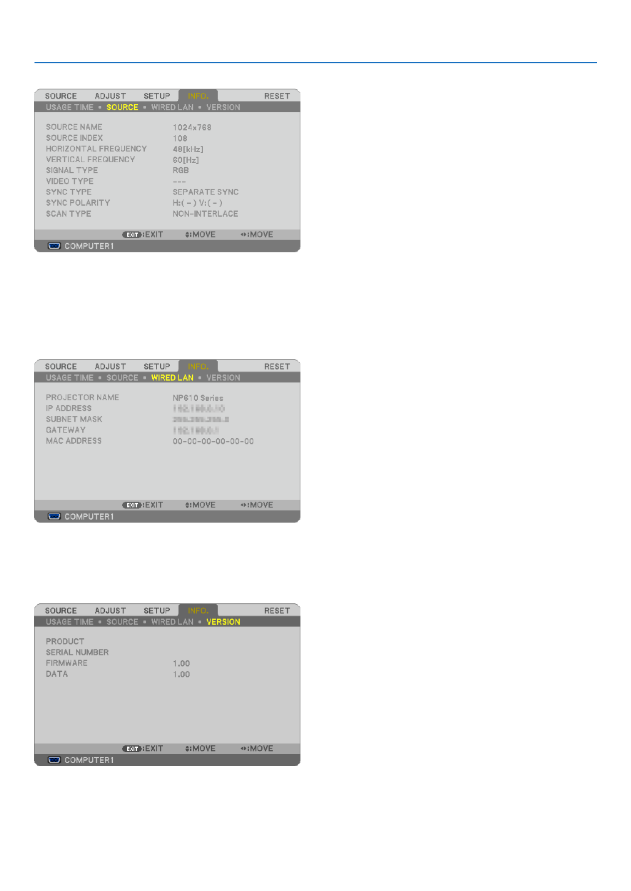
79
5. Using On-Screen Menu
[SOURCE]
[SOURCENAME] [SOURCEINDEX]
[HORIZONTALFREQUENCY] [VERTICALFREQUENCY]
[SIGNALTYPE] [VIDEOTYPE]
[SYNCTYPE] [SYNCPOLARITY]
[SCANTYPE]
[WIREDLAN](notavailableonNP405/NP305)
[PROJECTORNAME] [IPADDRESS]
[SUBNETMASK] [GATEWAY]
[MACADDRESS]
[VERSION]
[PRODUCT]
[SERIALNUMBER]
[FIRMWARE]Version
[DATA]Version
[CONTROLID](when[CONTROLID]isset)

80
5. Using On-Screen Menu
Menu Descriptions & Functions [RESET]
[NP610/NP510/NP410/NP310/NP510W/NP410W/
NP610S/NP510WS] [NP405/NP305]
ReturningtoFactoryDefault[RESET]
TheRESETfeatureallowsyoutochangeadjustmentsandsettingstothefactorypresetfora(all)source(s)except
thefollowing:
[CURRENTSIGNAL]
Resetstheadjustmentsforthecurrentsignaltothefactorypresetlevels.
Theitemsthatcanberesetare:[PRESET],[CONTRAST],[BRIGHTNESS],[COLOR],[HUE],[SHARPNESS],
[ASPECTRATIO],[HORIZONTAL],[VERTICAL],[CLOCK],[PHASE],and[OVERSCAN].
[ALLDATA]
Resetalltheadjustmentsandsettingsforallthesignalstothefactorypreset.
All items can be reset EXCEPT[LANGUAGE],[BACKGROUND],[FILTERMESSAGE],[SECURITY],[COMMUNI-
CATIONSPEED],[CONTROLID],[STANDBYMODE],[FANMODE],[LAMPLIFEREMAINING],[LAMPHOURS
USED],[FILTERHOURSUSED],[TOTALCARBONSAVINGS],and[NETWORKSETTINGS].
Toresetthelampusagetime,see“ClearingLampHourMeter[CLEARLAMPHOURS]”below.
ClearingNetworkingSettings[NETWORKSETTINGS](NotavailableonNP405/NP305)
Returns[DHCP],[IPADDRESS],[SUBNETMASK],and[GATEWAY]tothedefaultsettings.
ClearingLampHourMeter[CLEARLAMPHOURS]
Resetsthelampclockbacktozero.Selectingthisoptiondisplayssubmenuforaconrmation.Select[YES]andpress
theENTERbutton.
NOTE:Elapsedtimeofthelampusewillnotbeaffectedevenwhen[RESET]isdonefromthemenu.
NOTE:Theprojectorwillturnoffandgointostandbymodewhenyoucontinuetousetheprojectorforanother100hoursafterth
lamp has reached the end of its life. In this condition you cannot clear the lamp hour meter on the menu. If this happens, press the
HELPbuttonontheremotecontrolfor10secondstoresetthelampclockbacktozero.Dothisonlyafterreplacingthelamp.
ClearingtheFilterUsageHours[CLEARFILTERHOURS]
Resetsthelterusagebacktozero.Selectingthisoptiondisplayssubmenuforaconrmation.Select[YES]andpress
theENTERbutton.
NOTE:Elapsedtimeofthelterusewillnotbeaffectedevenwhen[RESET]isdonefromthemenu.

81
6. Maintenance
Thissectiondescribesthesimplemaintenanceproceduresyoushouldfollowtocleantheltersandreplacethelamp.
1 Cleaning or Replacing the Filters
Theair-lterspongekeepsdustanddirtfromgettinginsidetheprojectorandshouldbefrequentlycleaned.Ifthelter
is dirty or clogged, your projector may overheat.
NOTE: The message for lter cleaning will be displayed for one minute after the projector is turned on or off.
To cancel the message, press any button on the projector cabinet or the remote control.
CAUTION
• Turnofftheprojector,turnoffthemainpowerswitchandunplugtheprojectorbeforereplacingthelters.
• Onlycleantheoutsideoftheltercoverwithavacuumcleaner.
• Donotattempttooperatetheprojectorwithouttheltercover.
Tocleantheair-lter:
Vacuumthelter-throughtheltercover.
Toreplacethelter(sponge):
1. Remove the lter cover (2 locations) by pushing up on the catch of the cover until you feel it detach.
2. Replace two lters.
(1) Gently peel off the lter (sponge) and clean the lter cover.
(2) Attach the new lter to the lter cover.

82
6. Maintenance
3. Reinstall the new lter cover (2 locations).
• Inserttheltercoveruntilyoufeelclick.
4. Clear the lter hours used.
Toresetthelterusagetime,fromthemenu,select[RESET] [CLEARFILTERHOURS].→
( page for resetting the lter usage time.)→ 80
NOTE:Donotwashthelterwithsoapandwater.Soapandwaterwilldamagetheltermembrane.Beforereplacingthelter,remov
dustanddirtfromtheprojectorcabinet.Keepoutdustanddirtduringlterreplacement.
NOTE: When you replace the lamp, it is also wise to replace the lter. The lter comes in the same package with your replacement
lamp.

83
6. Maintenance
Cleaning the Cabinet and the Lens
1. Turn off the projector before cleaning.
2. Clean the cabinet periodically with a damp cloth. If heavily soiled, use a mild detergent. Never use strong
detergents or solvents such as alcohol or thinner.
Vacuum the ventilation
inlet of the cabinet.
NoteonCleaningtheLens(NP610/NP510/NP410/NP405/NP310/NP305/NP510W/NP410W)
Useablowerorlenspapertocleanthelens,andbecarefulnottoscratchormarthelens.
NoteonCleaningtheLens(NP610S/NP510WS)
TheNP610SandNP510WShaveaplasticlens.Useacommerciallyavailableplasticlenscleaner.
NOTE:
• Donotscratchormarthelenssurfaceasaplasticlensiseasilyscratched.
• Neverusealcoholorglasslenscleanerasdoingsowillcausedamagetothelenssurface.

84
6. Maintenance
Replacing the Lamp
Whenthelampreachestheendofitslife,theLAMPindicatorinthecabinetwillblinkred.Eventhoughthelampmay
stillbeworking,replacethelamptomaintaintheoptimalprojectorperformance.Afterreplacingthelamp,besureto
clear the lamp hour meter. ( page )→ 80
CAUTION
• DONOTTOUCHTHELAMPimmediatelyafterithasbeenused.Itwillbeextremelyhot.Turntheprojectoroff,
turnoffthemainpowerswitchandthendisconnectthepowercable.Allowatleastonehourforthelamptocool
before handling.
• DONOTREMOVEANYSCREWSexceptonelampcoverscrewandtwolamphousingscrews.Youcouldreceive
anelectricshock.
• Donotbreaktheglassonthelamphousing.
Keepngerprintsofftheglasssurfaceonthelamphousing.Leavingngerprintsontheglasssurfacemightcause
anunwantedshadowandpoorpicturequality.
• Theprojectorwillturnoffandgointostandbymodewhenyoucontinuetousetheprojectorforanother100hours
afterthelamphasreachedtheendofitslife.Ifthishappens,besuretoreplacethelamp.Ifyoucontinuetouse
the lamp after the lamp reaches the end of its life, the lamp bulb may shatter, and pieces of glass may be scattered
inthelampcase.Donottouchthemasthepiecesofglassmaycauseinjury.Ifthishappens,contactyourNEC
dealer for lamp replacement.
*NOTE: This message will be displayed under the following conditions:
• foroneminuteaftertheprojectorhasbeenpoweredon
• whenthe (POWER)buttonontheprojectorcabinetorthePOWEROFFbuttonontheremotecontrolispressed
To turn off the message, press any button on the projector cabinet or the remote control.
To replace the lamp:
Optionallampandtoolsneededforreplacement:
• Replacementlamp:
NP07LP(NP610/NP510W/NP410W/NP610S/NP510WS)
NP14LP(NP510/NP410/NP405/NP310/NP305)

85
6. Maintenance
2. Remove the lamp housing.
(1)Loosenthetwoscrewssecuringthelamphousinguntilthephillipsscrewdrivergoesintoafreewheelingcondi-
tion.
•Thetwoscrewsarenotremovable.
•Thereisaninterlockonthiscasetopreventtheriskofelectricalshock.Donotattempttocircumventthis
interlock.
(2)Removethelamphousingbyholdingit.
FOCUS
FOCUS
Interlock
1. Remove the lamp cover.
(1)Loosenthelampcoverscrew
•Thelampcoverscrewisnotremovable.
(2) Push and slide the lamp cover off.
M
ENU
S TUS TA
LAMP
AUTOADJ. SOURCE
FOCUS
M
ENU
S TUS TA
LAMP
AUTOADJ. SOURCE
FOCUS
CAUTION:
Makesurethatthelamphousingiscool
enough to before removing it.

86
6. Maintenance
5. Connect the supplied power cable, turn on the Main Power switch and turn on the projector.
6. Finally, select the menu [RESET] [CLEAR LAMP HOURS] to reset the lamp usage hours.→ →
NOTE:Whenyoucontinuetousetheprojectorforanother100hoursafterthelamphasreachedtheendofitslife,theprojecto
cannot turn on and the menu is not displayed.
Ifthishappens,presstheHELPbuttonontheremotecontrolfor10secondstoresetthelampclockbacktozero.
Whenthelamptimeclockisresettozero,theLAMPindicatorgoesout.
M
ENU
S TUSTA
LAMP
AUTOADJ.SOURCE
FOCUS
M
ENU
S TUS TA
LAMP
AUTOADJ. SOURCE
FOCUS
M
ENU
S TUS TA
LAMP
AUTOADJ. SOURCE
FOCUS
M
ENU
S TUS TA
LAMP
AUTOADJ. SOURCE
FOCUS
4. Reattach the lamp cover.
(1)Slidethelampcoverbackuntilitsnapsintoplace.
(2)Tightenthescrewtosecurethelampcover.
•Besuretotightenthescrew.
3. Install a new lamp housing.
(1)Insertanewlamphousinguntilthelamphousingispluggedintothesocket.
CAUTION
DonotusealampotherthantheNECreplacementlampNP07LP(NP610/NP510W/NP410W/NP610S/NP510WS)/
NP14LP(NP510/NP410/NP405/NP310/NP305).
OrderthisfromyourNECdealer.
(2) Push the top center of the lamp housing to secure it.
(3)Secureitinplacewiththetwoscrews.
•Besuretotightenthescrews.

88
7. Appendix
Common Problems & Solutions (→“Power/Status/LampIndicator”onpage87.)
Does not turn on
or shut down
Will turn off
No picture
Picture suddenly
becomes dark
Color tone or hue is
unusual
Image isn’t square to
the screen
Picture is blurred
Flicker appears on
screen
Image is scrolling
vertically, horizontally
or both
Remote control does
not work
Indicator is lit or blinking
Cross color in RGB
mode
Problem CheckTheseItems
Formoreinformationcontactyourdealer.
• Checkthatthepowercableispluggedinandthatthepowerbuttonontheprojectorcabinetortheremote
control is on. ( pages , , )→ 25 26 27
• Ensurethatthelampcoverisinstalledcorrectly.(→ page )86
• Checktoseeiftheprojectorhasoverheated.Ifthereisinsufcientventilationaroundtheprojectororifthe
room where you are presenting is particularly warm, move the projector to a cooler location.
• Checktoseeifyoucontinuetousetheprojectorforanother100hoursafterthelamphasreachedtheendof
its life. If so, replace the lamp. After replacing the lamp, reset the lamp hours used. ( page )→ 80
• Thelampmayfailtolight.Waitafullminuteandthenturnonthepoweragain.
• Set[FANMODE]to[HIGHALTITUDE]whenusingtheprojectorataltitudesapproximately5500feet/1600
meters or higher. Using the projector at altitudes approximately 5500 feet/1600 meters or higher without setting
to [HIGH ALTITUDE] can cause the projector to overheat and the projector could shut down. If this happens,
wait a couple minutes and turn on the projector. ( page )→ 74
If you turn on the projector immediately after the lamp is turned off, the fans run without displaying an im-
age for some time and then the projector will display the image. Wait for a moment.
• Ensurethatthe[OFFTIMER]or[AUTOPOWEROFF]isoff.(→ page , )76 77
• UsetheCOMPUTER1,theCOMPUTER2,theVIDEOortheS-VIDEObuttonontheremotecontroltoselect
your source (Computer, Video or S-Video). ( page ) If there is still no picture, press the button again.→ 29
• Ensureyourcablesareconnectedproperly.
• Usemenustoadjustthebrightnessandcontrast.(→ page )62
• Removethelenscap.
• Resetthesettingsoradjustmentstofactorypresetlevelsusingthe[RESET]intheMenu.(→ page )80
• EnteryourregisteredkeywordiftheSecurityfunctionisenabled.(→ page )43
• BesuretoconnecttheprojectorandnotebookPCwhiletheprojectorisinstandbymodeandbeforeturning
on the power to the notebook PC.
In most cases the output signal from the notebook PC is not turned on unless connected to the projector
before being powered up.
* If the screen goes blank while using your remote control, it may be the result of the computer’s screen-saver
or power management software.
• Seealsothenext page.
• CheckiftheprojectorisintheForcedECOmodebecauseoftoohighambienttemperature.Ifthisisthecase,
lower the internal temperature of the projector by selecting [HIGH] for [FAN MODE]. ( page )→ 74
• Checkifanappropriatecolorisselectedin[WALLCOLOR].Ifso,selectanappropriateoption.(→ page )69
• Adjust[HUE]in[PICTURE].(→ page )63
• Repositiontheprojectortoimproveitsangletothescreen.(→ page )30
• UsetheKeystonecorrectionfunctiontocorrectthetrapezoiddistortion.(→ page )34
• Adjustthefocus.(→ page )33
• Repositiontheprojectortoimproveitsangletothescreen.(→ page )30
• Ensure that thedistance between the projector and screen is within the adjustmentrange of the lens.
( page , )→ 15 16
• Condensationmayformonthelensiftheprojectoriscold,broughtintoawarmplaceandisthenturnedon.
Should this happen, let the projector stand until there is no condensation on the lens.
•
Set [FAN MODE] to other than [HIGH ALTITUDE] mode when using the projector at altitudes approximately 5500 feet/1600
meters or lower. Using the projector at altitudes less than approximately 5500 feet/1600 meters and setting to [HIGH
ALTITUDE] can cause the lamp to overcool, causing the image to icker. Switch [FAN MODE] to [AUTO]. ( page → 74)
• Checkthecomputer’sresolutionandfrequency.Makesurethattheresolutionyouaretryingtodisplayis
supported by the projector. ( page )→ 97
• AdjustthecomputerimagemanuallywiththeHorizontal/Verticalinthe[IMAGEOPTIONS].(→ page )65
• Installnewbatteries.(→ page )10
• Makesuretherearenoobstaclesbetweenyouandtheprojector.
• Standwithin22feet(7m)oftheprojector.(→ page )10
• SeethePOWER/STATUS/LAMPIndicator.(→ page )87
• PresstheAUTOADJ.buttonontheprojectorcabinetortheremotecontrol.(→ page )37
• Adjustthecomputerimagemanuallywith[CLOCK]/[PHASE]in[IMAGEOPTIONS]inthemenu.(→ page )64

89
7. Appendix
Ifthereisnopicture,orthepictureisnotdisplayedcorrectly.
• PoweronprocessfortheprojectorandthePC.
BesuretoconnecttheprojectorandnotebookPCwhiletheprojectorisinstandbymodeandbeforeturningon
thepowertothenotebookPC.
InmostcasestheoutputsignalfromthenotebookPCisnotturnedonunlessconnectedtotheprojectorbefore
beingpoweredup.
NOTE:Youcancheckthehorizontalfrequencyofthecurrentsignalintheprojector’smenuunderInformation.Ifitreads“0kHz
thismeansthereisnosignalbeingoutputfromthecomputer.( orgotonextstep)→ page 79
• Enablingthecomputer’sexternaldisplay.
DisplayinganimageonthenotebookPC’sscreendoesnotnecessarilymeanitoutputsasignaltotheprojector.
WhenusingaPCcompatiblelaptop,acombinationoffunctionkeyswillenable/disabletheexternaldisplay.Usu-
ally,thecombinationofthe“Fn”keyalongwithoneofthe12functionkeysgetstheexternaldisplaytocomeon
oroff.Forexample,NEClaptopsuseFn+F3,whileDelllaptopsuseFn+F8keycombinationstotogglethrough
external display selections.
• Non-standardsignaloutputfromthecomputer
IftheoutputsignalfromanotebookPCisnotanindustrystandard,theprojectedimagemaynotbedisplayed
correctly.Shouldthishappen,deactivatethenotebookPC’sLCDscreenwhentheprojectordisplayisinuse.Each
notebookPChasadifferentwayofdeactivate/reactivatethelocalLCDscreensasdescribedinthepreviousstep.
Refertoyourcomputer’sdocumentationfordetailedinformation.
• ImagedisplayedisincorrectwhenusingaMacintosh
WhenusingaMacintoshwiththeprojector,settheDIPswitchoftheMacadapter(notsuppliedwiththeprojector)
accordingtoyourresolution.Aftersetting,restartyourMacintoshforthechangestotakeaffect.
ForsettingdisplaymodesotherthanthosesupportedbyyourMacintoshandtheprojector,changingtheDIPswitch
onaMacadaptermaybounceanimageslightlyormaydisplaynothing.Shouldthishappen,settheDIPswitch
tothe13"xedmodeandthenrestartyourMacintosh.Afterthat,restoretheDIPswitchestoadisplayablemode
andthenrestarttheMacintoshagain.
NOTE:AVideoAdaptercablemanufacturedbyAppleComputerisneededforaPowerBookwhichdoesnothaveaminiD-S
15-pinconnector.
• MirroringonaPowerBook
* WhenusingtheprojectorwithaMacintoshPowerBook,outputmaynotbesetto1024x768unless“mirroring”
isoffonyourPowerBook.Refertoowner’smanualsuppliedwithyourMacintoshcomputerformirroring.
• FoldersoriconsarehiddenontheMacintoshscreen
Foldersoriconsmaynotbeseenonthescreen.Shouldthishappen,select[View] [Arrange]fromtheApple→
menu and arrange icons.

90
7. Appendix
Specications
This section provides technical information about projector’s performance.
ModelNumber NP610/NP510/NP410/NP405/NP310/NP305/NP510W/NP410W
Optical NP610/NP510/NP410/NP405/NP310/NP305 NP510W/NP410W
LCDPanel 0.63inchLCDwithMicroLensArrayNP610/NP510:
(AspectRatio4:3)
NP410/NP405/NP310/NP305:0.63inchLCD(As-
pectRatio4:3)
0.59inchLCDwithMicroLensArray
(AspectRatio16:10)
Resolution 1024 × 768 pixels* 11280 × 800 pixels* 1
Lens Manualzoomandfocus
ZoomRatio=1–1.2
F1.7–2.0 f=19.8–23.7mm
Lamp 230WAC(170WinECOMode)NP610:
NP510/NP410/NP405/NP310/NP305: 180W AC
(145WECOMode)
230WAC(170WinECOMode)
LightOutput*2*
3NP610:3500lumens(approx.70%inECOMode)
NP510:3000lumens(approx.80%inECOMode)
NP410/NP405:2600lumens(approx.80%inECO
Mode)
NP310/NP305:2200lumens(approx.80%inECO
Mode)
NP510W:3000lumens(approx.70%inECO
Mode)
NP410W:2600lumens(approx.70%inECO
Mode)
ContrastRatio* 3
(fullwhite:fullblack)
NP610/NP510/NP405/NP305:500:1
NP410/NP310:2000:1
NP510W:500:1
NP410W:450:1
ImageSize(Diagonal) 21–300inches/0.53m–7.6m
ProjectionDistance 30–444inches/0.7–11.3m 31–470inches/0.8–11.9m
Projection Angle Tele:7.9°–8.3°/Wide:9.5°–10.0° Tele:7.9°–8.3°/Wide:9.5°–10.0°
*1 Effectivepixelsaremorethan99.99%.
*2 Thisisthelightoutputvalue(lumens)whenthe[PRESET]modeissetto[HIGH-BRIGHT].Ifany
othermodeisselectedasthe[PRESET]mode,thelightoutputvaluemaydropslightly.
*3 CompliancewithISO21118-2005
Electrical
Inputs 1RGB/Component(D-Sub15P),1RGB(Digital/Analog,DVI-I29P,HDCP* 4 supported),
1S-Video(DIN4P),1Video(RCA),1(L/R)RCAAudio,2StereoMiniAudio
DVI-I29PisnotavailableonNP405/NP305
Outputs 1RGB(D-Sub15P),1StereoMiniAudio
PCControl 1PCControlPort(D-Sub9P)
WiredLANPort RJ-45(notavailableonNP405/NP305)
ExternalControl RS232,IR,WiredLAN(notavailableonNP405/NP305)
ColorReproduction 16.7millioncolorssimultaneously,Fullcolor
CompatibleSignals* 5Analog:VGA/SVGA/XGA/WXGA/WXGA+/SXGA/SXGA+/UXGA
480i/480p/576i/576p/720p/1080i
Digital:VGA/SVGA/XGA/WXGA/SXGA
VideoBandwidth RGB:80MHz(Max.)
HorizontalResolution 540TVlines:NTSC/NTSC4.43/PAL/PAL-M/PAL-N/PAL60
300TVlines:SECAM
ScanRate Horizontal:15kHzto100kHz(RGB:24kHzorover)
Vertical:50Hzto120Hz
SyncCompatibility SeparateSync/CompositeSync/SynconG
Built-inSpeaker 7W (monaural)
PowerRequirement NP610/NP510/NP410/NP405/NP310/NP305:
100–240VAC,50/60Hz
NP610G/NP510G/NP410G/NP405G/NP310G/
NP305G:200–240VAC,50/60Hz
NP510W/NP410W:100–240VAC,50/60Hz
NP510WG/NP410WG:200–240VAC,50/60Hz

91
7. Appendix
InputCurrent NP610: 3.8–1.5A
NP510/NP410/NP405/NP310/NP305: 3.2–1.4A
NP610G: 1.8A
NP510G/NP410G/NP310G/NP405G/NP305G:
1.5A
NP510W/NP410W:3.8–1.5A
NP510WG/NP410WG: 1.8A
PowerConsumption 312W(100-130V AC)/294W(200-240VNP610:
AC) in OFF for ECO MODE/237W(100-130V
AC)/228W(200-240VAC)inONforECOMODE
NP510/NP410/NP310/NP405/NP305: 251W(100-
130V AC)/239W(200-240V AC) in OFF for ECO
MODE/203W(100-130V AC)/195W(200-240V AC)
inONforECOMODE
NP610/NP510/NP410/NP310: 10W in NORMAL
Mode for STANDBY MODE/0.6W(100-130V
AC)/0.7W(200-240VAC)inPOWER-SAVINGMode
forSTANDBYMODE
NP405/NP305:8WinNORMALModeforSTANDBY
MODE/0.6W(100-130VAC)/0.7W(200-240VAC)in
POWER-SAVINGModeforSTANDBYMODE
NP510W/NP410W:312W(100-130VAC)/294W(200-
240VAC)inOFFforECOMODE/237W(100-130V
AC)/228W(200-240VAC)inONforECOMODE
1 0 W i n N O R M A L M o d e fo r S TA N D B Y
MODE/0.6W(100-130V AC)/0.7W(200-240V AC)
inPOWER-SAVINGModeforSTANDBYMODE
*4 WhatisHDCP/HDCPtechnology?
HDCPisanacronymforHigh-bandwidthDigitalContentProtection.HighbandwidthDigitalContent
Protection(HDCP)isasystemforpreventingillegalcopyingofvideodatasentoveraDigitalVisual
Interface(DVI).
IfyouareunabletoviewmaterialviatheDVIinput,thisdoesnotnecessarilymeantheprojector
isnotfunctioningproperly.WiththeimplementationofHDCP,theremaybecasesinwhichcertain
contentisprotectedwithHDCPandmightnotbedisplayedduetothedecision/intentionoftheHDCP
community(DigitalContentProtection,LLC).
*5 Animagewithhigherorlowerresolutionthantheprojector’snativeresolution(NP610/NP510/NP410/
NP405/NP310/NP305:1024×768/NP510W/NP410W:1280×800)willbedisplayedwithAdvanced
AccuBlend.
Mechanical
Installation Orientation:Desktop/Front,Desktop/Rear,Ceiling/Front,Ceiling/Rear
Dimensions 12.1"(W)×3.7"(H)×10.3"(D)/308mm(W)×93.5mm(H)×262mm(D)
(not including protrusions)
Weight NP610/NP510: 6.59lbs/2.99kg
NP410/NP310:6.61lbs/3.0kg
NP405/NP305:6.59lbs/2.97kg
NP510W/NP410W:6.59lbs/2.99kg
Environmental
Considerations
OperationalTemperatures:41°to104°F(5°to40°C),
(ECOmodeselectedautomaticallyat95°Fto104°F/35°Cto40°C)
20%to80%humidity(non-condensing)
StorageTemperatures:14°to122°F(-10°to50°C),
20%to80%humidity(non-condensing)
Regulations UL/C-ULApproved(UL60950-1,CSA60950-1)
MeetsDOCCanadaClassBrequirements
MeetsFCCClassBrequirements
MeetsAS/NZSCISPR.22ClassB
MeetsEMCDirective(EN55022,EN55024,EN61000-3-2,EN61000-3-3)
MeetsLowVoltageDirective(EN60950-1,TÜVGSApproved)

92
7. Appendix
ModelNumber NP610S/NP510WS
Optical NP610S NP510WS
LCDPanel 0.63inchLCDwithMicroLensArray
(AspectRatio4:3)
0.59inchLCDwithMicroLensArray
(AspectRatio16:10)
Resolution 1024 × 768 pixels* 11280 × 800 pixels* 1
Lens Fixedzoomandmanualfocus
DigitalZoomRatio=1.2
F2.3 f=9.7mm
Lamp 230WAC(170WinECOMode)
LightOutput*2*
32600lumens(approx.70%inECOMode) 2100lumens(approx.70%inECOMode)
ContrastRatio* 3
(fullwhite:fullblack)
600:1
ImageSize(Diagonal) 60"–110"/1.52m–2.79m 57"–104"/1.45m–2.64m
ProjectionDistance 35"–66"/0.9m–1.7m
Projection Angle 29.1°–29.4°
*1 Effectivepixelsaremorethan99.99%.
*2 Thisisthelightoutputvalue(lumens)whenthe[PRESET]modeissetto[HIGH-BRIGHT].Ifany
othermodeisselectedasthe[PRESET]mode,thelightoutputvaluemaydropslightly.
*3 CompliancewithISO21118-2005
Electrical
Inputs 1RGB/Component(D-Sub15P),1RGB(Digital/Analog,DVI-I29P,HDCP* 4 supported),
1S-Video(DIN4P),1Video(RCA),1(L/R)RCAAudio,2StereoMiniAudio
Outputs 1RGB(D-Sub15P),1StereoMiniAudio
PCControl 1PCControlPort(D-Sub9P)
WiredLANPort RJ-45
ExternalControl RS232,IR,WiredLAN
ColorReproduction 16.7millioncolorssimultaneously,Fullcolor
CompatibleSignals* 5Analog:VGA/SVGA/XGA/WXGA/WXGA+/SXGA/SXGA+/UXGA
480i/480p/576i/576p/720p/1080i
Digital:VGA/SVGA/XGA/WXGA/SXGA
VideoBandwidth RGB:80MHz(Max.)
HorizontalResolution 540TVlines:NTSC/NTSC4.43/PAL/PAL-M/PAL-N/PAL60
300TVlines:SECAM
ScanRate Horizontal:15kHzto100kHz(RGB:24kHzorover)
Vertical:50Hzto120Hz
SyncCompatibility SeparateSync/CompositeSync/SynconG
Built-inSpeaker 7W (monaural)
PowerRequirement 100–240VAC,50/60HzNP610S:
NP610SG:200–240VAC,50/60Hz
NP510WS:100–240VAC,50/60Hz
NP510WSG:200–240VAC,50/60Hz
InputCurrent NP610S: 3.8–1.5A
NP610SG: 1.8A
NP510WS:3.8–1.5A
NP510WSG: 1.8A
PowerConsumption 312W(100-130VAC)/294W(200-240VAC)inOFFforECOMODE/237W(100-130VAC)/228W(200-240V
AC)inONforECOMODE/10WinNORMALModeforSTANDBYMode/0.6W(100-130VAC)/0.7W(200-
240VAC)inPOWER-SAVINGModeforSTANDBYMODE
*4 WhatisHDCP/HDCPtechnology?
HDCPisanacronymforHigh-bandwidthDigitalContentProtection.HighbandwidthDigitalContent
Protection(HDCP)isasystemforpreventingillegalcopyingofvideodatasentoveraDigitalVisual
Interface(DVI).
IfyouareunabletoviewmaterialviatheDVIinput,thisdoesnotnecessarilymeantheprojector
isnotfunctioningproperly.WiththeimplementationofHDCP,theremaybecasesinwhichcertain
contentisprotectedwithHDCPandmightnotbedisplayedduetothedecision/intentionoftheHDCP
community(DigitalContentProtection,LLC).
*5 Animagewithhigherorlowerresolutionthantheprojector’snativeresolution(NP610S:1024×768/
NP510WS:1280×800)willbedisplayedwithAdvancedAccuBlend.

93
7. Appendix
Mechanical
InstallationOrientation Desktop/Front,Desktop/Rear,Ceiling/Front,Ceiling/Rear
Dimensions 12.1"(W)×5.4"(H)×11.9"(D)/308mm(W)×136mm(H)×301mm(D)
(not including protrusions)
Weight 7.28lbs/3.3kg
Environmental
Considerations
OperationalTemperatures:41°to104°F(5°to40°C),
(ECOmodeselectedautomaticallyat95°Fto104°F/35°Cto40°C)
20%to80%humidity(non-condensing)
StorageTemperatures:14°to122°F(-10°to50°C),
20%to80%humidity(non-condensing)
Regulations UL/C-ULApproved(UL60950-1,CSA60950-1)
MeetsDOCCanadaClassBrequirements
MeetsFCCClassBrequirements
MeetsAS/NZSCISPR.22ClassB
MeetsEMCDirective(EN55022,EN55024,EN61000-3-2,EN61000-3-3)
MeetsLowVoltageDirective(EN60950-1,TÜVGSApproved)
Foradditionalinformationvisit:
US:http://www.necdisplay.com/
Europe:http://www.nec-display-solutions.com/
Global:http://www.nec-display.com/global/index.html
Forinformationonouroptionalaccessories,visitourwebsiteorseeourbrochure.
Thespecicationsaresubjecttochangewithoutnotice.

94
7. Appendix
MENU
EXIT
ENTER
STAT US
LAMP
AUTO ADJ.SOURCE
FOCUS
263 (10.4")
78 (3.1")
108.5 (4.3")
55.3 (2.2")
76 (3.0")
308 (12.1")
Cabinet Dimensions
NP610/NP510/NP410/NP405/NP310/NP305/NP510W/NP410W
Lens center
Lens center
Unit:mm(inch)
NP405/NP305
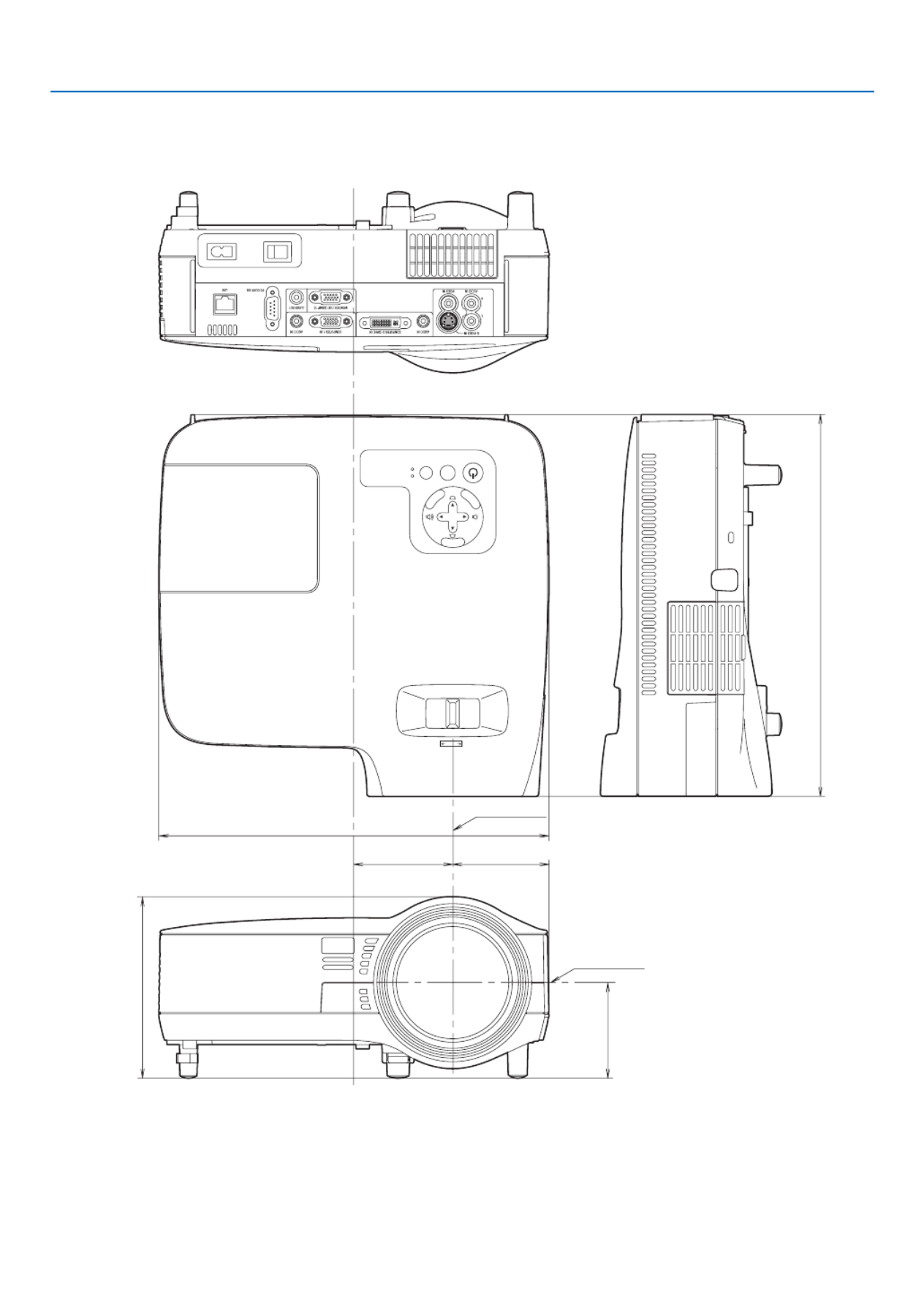
95
7. Appendix
NP610S/NP510WS
MENU
EXIT
ENTER
STATUS
LAMP
AUTO ADJ.SOURCE
FOCUS
78 (3.1")
308 (12.1")
76 (3")
143.2 (5.6")
301.5 (11.9")
75.5 (3")
Lens center
Lens center
Unit:mm(inch)

96
7. Appendix
Mini D-Sub 15 Pin Connector
Pin Assignments of D-Sub COMPUTER Input Connector
SignalLevel
Videosignal:0.7Vp-p(Analog)
Syncsignal:TTLlevel
51 42 3
10
11 12 13 14 15
6 97 8
NOTE:PinNos.12and15arerequiredforDDC/CI.
PinNo. RGBSignal(Analog) YCbCrSignal
1 Red Cr
2 GreenorSynconGreen Y
3 Blue Cb
4 Ground
5 Ground
6 RedGround CrGround
7 GreenGround YGround
8 BlueGround CbGround
9 NoConnection
10 Sync Signal Ground
11 NoConnection
12 Bi-directionalDATA(SDA)
13
HorizontalSyncorCompositeSync
14 VerticalSync
15 DataClock

97
7. Appendix
Compatible Input Signal List
Horizontal:15KHzto100KHz(RGB:24KHzorover)
Vertical:50Hzto120Hz
Signal Resolution
(Dots)
FrequencyH.
(kHz)
RefreshRate
(Hz)
VIDEO NTSC - * 15.7 59.9
PAL - * 15.6 50.0
PAL60 - * 15.7 60.0
SECAM - * 15.6 50.0
IBM 640 × 480 31.5 59.9
640 × 480 31.5 60.0
640 × 480 37.9 72.8
640 × 480 37.5 75.0
640 × 480 39.4 75.0
640 × 480 43.3 85.0
800 × 600 35.2 56.3
800 × 600 37.9 60.3
800 × 600 48.1 72.2
800 × 600 46.9 75.0
800 × 600 53.7 85.1
1024 × 768 48.4 60.0
1024 × 768 56.5 70.1
1024 × 768 60.0 75.0
1024 × 768 68.7 85.0
1152 × 864 54.4 60.1
1152 × 864 64.0 70.0
1152 × 864 67.5 75.0
1152 × 864 * 77.5 85.1
1280 × 768 47.8 59.9
1280 × 800 49.7 59.8
1280 × 960 60.0 60.0
1280 × 960 * 75.0 75.0
1280 × 960 * 85.9 85.0
1280 × 1024 64.0 60.0
1280 × 1024 * 80.0 75.0
1280 × 1024 * 91.2 85.0
1400 × 1050 64.7 60.0
1400 × 1050 * 65.3 60.0
1440 × 900 * 55.9 59.9
1600 × 1200 * 75.0 60.0
1600 × 1200 * 81.3 65.0
1600 × 1200 * 87.5 70.0
1600 × 1200 * 93.8 75.0
AppleMacintosh® 640 × 480 35.0 66.7
832 × 624 49.7 74.6
1024 × 768 60.2 74.9
1152 × 870 68.7 75.1
1280 × 1024 64.3 60.4
1280 × 1024 * 69.9 65.2
1280 × 1024 * 78.4 73.7
HDTV (1080i/60) 1920 × 1080 33.8 60.0
(1080i/50) 1920 × 1080 28.1 50.0
1280 × 720 45.0 60.0
SDTV 480p 720 × 480 31.5 59.9
DVD YCbCr 720 × 480 15.7 59.9
720 × 576 15.6 50.0
Progressive 720 × 480 * 31.5 59.9
720 × 576 31.3 50.0
NOTE:
• Imagesaboveaggedwith“*”arenotsupportedbydigitalsignal.
• Animagewithhigherorlowerresolutionthantheprojector’snativeresolution(NP610/NP510/NP410/NP405/NP310/NP305/
NP610S:1024x768/NP510W/NP410W/NP510WS:1280x800)willbedisplayedwithAdvancedAccuBlend.
• Somecompositesyncsignalsmaynotbedisplayedcorrectly.
Signals other than those specied in the table above may not be displayed correctly. If this should happen, change the refresh
rateorresolutiononyourPC.RefertoDisplayPropertieshelpsectionofyourPCforprocedures.

98
7. Appendix
NOTE: Contact your local dealer for a full list of the PC Control Codes if needed.
Cable Connection
CommunicationProtocol
Baud rate .........................................19200 bps
Data length ......................................8 bits
Parity ...............................................No parity
Stop bit ............................................One bit
X on/off ............................................None
Communications procedure .............Full duplex
NOTE:Dependingontheequipment,alowerbaudratemayberecommendedforlongcableruns.
PC Control Connector (D-SUB 9P)
PC Control Codes and Cable Connection
PC Control Codes
Function Code Data
POWER ON 02H 00H 00H 00H 00H 02H
POWER OFF 02H 01H 00H 00H 00H 03H
INPUT SELECT COMPUTER 1 02H 03H 00H 00H 02H 01H 01H 09H
INPUT SELECT COMPUTER 2 (Digital)
02H 03H 00H 00H 02H 01H 1AH 22H
INPUT SELECT COMPUTER 2 (Analog)
02H 03H 00H 00H 02H 01H 02H 0AH
INPUT SELECT VIDEO 02H 03H 00H 00H 02H 01H 06H 0EH
INPUT SELECT S-VIDEO 02H 03H 00H 00H 02H 01H 0BH 13H
PICTURE MUTE ON 02H 10H 00H 00H 00H 12H
PICTURE MUTE OFF 02H 11H 00H 00H 00H 13H
SOUND MUTE ON 02H 12H 00H 00H 00H 14H
SOUND MUTE OFF 02H 13H 00H 00H 00H 15H
NOTE1:Pins1,4,6and9arenoused.
NOTE2:Jumper“RequesttoSend”and“CleartoSend”togetheronbothendsofthecabletosimplifycableconnection.
NOTE3:Forlongcablerunsitisrecommendedtosetcommunicationspeedwithinprojectormenusto9600bps.
1 52 43
6 7 98
To GND of PC
To RxD of PC
To TxD of PC
To RTS of PC
To CTS of PC

100
7. Appendix
In the space below please describe your problem in detail.
Information on application and environment where your projector is used
Projector
Model number:
Serial No.:
Date of purchase:
Lamp operating time (hours):
Eco Mode: Off On
Information on input signal:
Horizontal synch frequency [ ] kHz
Vertical synch frequency [ ] Hz
Synch polarity H (+) (−)
V (+) (−)
Synch type Separate Composite
Sync on Green
STATUS Indicator:
Steady light Orange Green
Flashing light [ ] cycles
Remote control model number:
Signalcable
NEC standard or other manufacturer’s cable?
Model number: Length: inch/m
Distribution amplier
Model number:
Switcher
Model number:
Adapter
Model number:
Projector PC
DVD player
Installation environment
Screen size: inch
Screen type: White matte Beads Polarization
Wide angle High contrast
Throw distance: feet/inch/m
Orientation: Ceiling mount Desktop
Power outlet connection:
Connected directly to wall outlet
Connected to power cord extender or other (the
number of connected equipment______________)
Connected to a power cord reel or other (the number
of connected equipment______________)
Computer
Manufacturer:
Model number:
Notebook PC / Desktop
Native resolution:
Refresh rate:
Video adapter:
Other:
Videoequipment
VCR, DVD player, Video camera, Video game or other
Manufacturer:
Model number:

101
7. Appendix
TravelCare Guide
TravelCare - a service for international travelers
This product is eligible for “TravelCare”, NEC’s unique international
warranty.
PleasenotethatTravelCarecoveragediffersinpartfromcoverageunder
thewarrantyincludedwiththeproduct.
Services offered with TravelCare
Thiswarrantyallowscustomerstoreceiveserviceontheirproductatthe
NECandNEC-designatedservicestationsinthecountrieslistedherein
whentemporarilytravelinginternationallyforbusinessorpleasure.
Fordetailsonservicesofferedbythedifferentservicestations,please
refertothe“ListofTravelCareOutlets”below.
1 Repair services
Theproductwillberepairedanddeliveredwithin10businessdays,
not including shipping time.
Duringthetermofwarranty,thecostofmaintenanceparts,laborcosts
forrepairsandshippingcostswithintheservicestation’scoverage
areaarecoveredbythewarranty.
2 Replacement product rental service
Ifthecustomerdesires,heorshecanrentareplacementproduct
whiletheoriginalproductisbeingrepaired.
Fee:US$200for12days
This fee must be paid at the local service station in cash or credit
card.
TheUS$200rentalfeeisnon-refundableevenifthecustomerrents
it less than 12 days before returning.
Thereplacementproductwillbedeliveredwithin3businessdays.
Ifthecustomerdidnotreturnthereplacementproductwithin12days,
thecustomerwillbechargedthepriceoftheunit.
Ifthecustomerreturnedthereplacementproductinafaultyordam-
agedcondition,therepaircostwillbechargedtothecustomer.
Note that this service is not offered in all countries and regions. Please
refertothe“ListofTravelCareOutlets”.
Inaddition,thisreplacementproductrentalserviceisnotofferedafter
theproduct’swarrantyhasexpired.
Term of warranty
1
a. Upon presentation of the warranty or receipt received upon
purchase:
Valid for the term indicated on the warranty or the normal term
of warranty for the country of purchase.
b. When only the product is brought in:
Valid for a period of within 14 months of the date of manufacture
indicated by the serial number attached to the product.
2 Whenaproductwhosetermofwarrantyisexpiredisbroughtin:
Repairswillbeofferedforafee.Inthiscasethecustomerisnoteligible
for the replacement product rental service.
3 Inthefollowingcases,repairsmaybecharged,eveniftheproduct’s
warrantyisstillineffect:
1) If the term of warranty, model name, serial number and name of
the store of purchase are not indicated on the warranty or have
been altered.
2) Problemsordamagecausedbydroppingorshocksduringship-
ment or movement by the customer or by improper handling by
the customers.
3) Problems or damage caused by improper usage or unwarrantable
alterations or repairs by the customer.
4) Problems or damage caused by fire, salt damage, gas damage,
earthquakes,lightningdamage,stormorooddamageorother
natural disasters or such external factors as dust, cigarette
smoke,abnormalvoltage,etc.
5) Problems or damage caused by use in hot or humid places, in
vehicles, boats or ships, etc.
6) Problems or damage caused by expendable supplies or devices
connected to the product other than those designated by NEC.
7) Problems caused by natural consumption, wear or deterioration
of parts under normal usage conditions.
8) Problems or damage to lamps and other expendable supplies,
included parts or optional parts.
9) Other conditions stipulated in the warranty included with the
product also apply.
NOTE: The product can be used overseas with voltages indicated in the rating
label on the product by using a power cable suited for the standards and power
source voltage of the country in which the product is being used.
List of TravelCare Outlets
This list applies as of July 1, 2009.
Forthemostup-to-dateinformation,pleaserefertothewebsitesofthe
servicestationsinthevariouscountriesontheListofTravelCareOutlets
ortotheNECwebsiteathttp://www.nec-display.com/global/index.html
In Europe
NECEuropeLtd./EuropeanTechnicalCentre
Address: UnitG,StaffordPark12,TelfordTF33BJ,U.K.
Telephone: +441952237000
FaxLine: +441952237006
EmailAddress: AFR@uk.neceur.com
WEBAddress: http://www.neceur.com
(RegionsCovered)
EU: Austria*, Belgium*, Bulgaria*, Czech Republic*, Cyprus*,
Denmark*,Estonia*,Finland*,France*,Germany*,Greece*,
Hungary*,Ireland*,Italy*,Latvia*,Lithuania*,Luxembourg*,
Malta*,TheNetherlands*, Poland*,Portugal*, Romania*,
Slovakia*, Slovenia*, Spain*, Sweden* and the United
Kingdom*
EEA: Norway*,IcelandandLiechtenstein
In North America
NECDisplaySolutionsofAmerica,Inc.
Address: 500ParkBoulevard,Suite1100Itasca,Illinois
60143,U.S.A.
Telephone: +18008360655
FaxLine: +18003562415
EmailAddress: vsd.tech-support@necdisplay.com
WEBAddress: http://www.necdisplay.com/
(RegionsCovered)
U.S.A.*,Canada*
In Oceania
AWALimited.
Address: 151ArthurStreet
HomebushWestNSW2140Australia
CustomerCallCentre
Telephone: 0297647777
FaxLine: 1300772688
EmailAddress: commercialsupport@awa.com.au
ForTravelCareservice,whilecustomerisinAustralia,thecustomer
willcontactAWAon1300366144,selectOption4.Ifyouwantto
bookwarrantyservicebyemailcustomergoesto:
commercialsupport@awa.com.au.
(RegionsCovered)
Australia
VisualGroupLtd.
Address: 28WallsRoadPenroseAucklandNewZealand
Telephone: 095250740
FaxLine: 095809607
EmailAddress: sarah.reed@visualgroup.co.nz
(RegionsCovered)
NewZealand

102
7. Appendix
HyosungITXCo.,Ltd.
Address: 1st Fl., Ire B/D. #2, 4Ga,Yangpyeng-Dong,
Youngdeungpo-Gu,Seoul,Korea150-967
Telephone: +82221634193
FaxLine: +82221634196
EmailAddress: moneybear@hyosung.com
(RegionsCovered)
SouthKorea
LensoCommunicationCo.,Ltd.
Address: 292LensoHouse4,1stFloor,SrinakarinRoad,
Huamark,Bangkapi,Bangkok10240,Thailand
Telephone: +6623752425
FaxLine: +6623752434
EmailAddress: pattara@lenso.com
WEBAddress: http://www.lensocom.com/
(RegionsCovered)
Thailand
ABBAElectronicsL.L.C.
Address: TariqBinZiyadRoad,P.O.Box327,Dubai,United
ArabEmirates
Telephone: +9714371800
FaxLine: +9714364283
EmailAddress: ABBA@emirates.net.ae
(RegionsCovered)
UnitedArabEmirates
Samir Photographic Supplies
Address: P.O.Box599,Jeddah21421,SaudiArabia
Telephone: +96626828219
FaxLine: +96626830820
EmailAddress: asif@samir-photo.com
Riyadh
Address: P.O.Box5519,Riyadh11432,SaudiArabia
Telephone: +96614645064
FaxLine: +96614657912
EmailAddress: bhimji@samir-photo.com
Alkhobar
Address: P.O.Box238,Alkhobar31952,SaudiArabia
Telephone: +96638942674
FaxLine: +96638948162
EmailAddress: chamsedin@samir-photo.com
(RegionsCovered)
Saudi Arabia
NOTE:Incountriesdesignatedwithanasterisk(*),replacementproductrental
service are offered.
In Asia and Middle East
NECDisplaySolutions,Ltd.
Address: 686-1, Nishioi, Oi-Machi, Ashigarakami-Gun,
Kanagawa258-0017,Japan
Telephone: +81465852369
FaxLine: +81465852393
EmailAddress: support_pjweb@gw.necds.nec.co.jp
WEBAddress: http://www.nec-pj.com
(RegionsCovered)
Japan*
NECSolutions(China)Co.,Ltd.
Address: Rm1903,ShiningBuilding,35XueyuanRd,
HaidianDistrictBeijing100083,P.R.C.
Telephone: +861082317788
FaxLine: +861082331722
EmailAddress: Lily@necsl.com.cn
Johnson_liu@necsl.com.cn
WEBAddress: http://www.necsl.com.cn
(RegionsCovered)
China
NECHongKongLtd.
Address: 25/F.,TheMetropolisTower,10MetropolisDrive,
Hunghom,Kowloon,HongKong
Telephone: +85223690335
FaxLine: +85227956618
EmailAddress: nechksc@nechk.nec.com.hk
esmond_au@nechk.nec.com.hk
WEBAddress: http://www.nec.com.hk
(RegionsCovered)
HongKong
NECTaiwanLtd.
Address: 7F,No.167,SEC.2,NanKingEastRoad,Taipei,
Taiwan,R.O.C.
Telephone: +886285001700
FaxLine: +886285001420
EmailAddress: eric@nec.com.tw
WEBAddress: http://www.nec.com.tw
(RegionsCovered)
Taiwan
NECAsiaPte.Ltd.
Address: 401 Commonwealth Drive, #07-02, Haw Par
Technocentre, Singapore 149598
Telephone: +6562738333
FaxLine: +6562742226
EmailAddress: ncare@nec.com.sg
WEBAddress: http://www.nec.com.sg/home.php
(RegionsCovered)
Singapore
NECCorporationofMalaysiaSdn.Bhd.
Address: 33rdFloor,MenaraTAOne,22,JalanP.Ramlee,
50250KualaLumpur,Malaysia
Telephone: +60321783600(ISDN)
FaxLine: +60321783789
EmailAddress: necare@nsm.nec.co.jp
WEBAddress: http://www.necarecenter.com
(RegionsCovered)
Malaysia
Produktspezifikationen
| Marke: | NEC |
| Kategorie: | Beamer |
| Modell: | NP405 |
Brauchst du Hilfe?
Wenn Sie Hilfe mit NEC NP405 benötigen, stellen Sie unten eine Frage und andere Benutzer werden Ihnen antworten
Bedienungsanleitung Beamer NEC

14 Oktober 2024
5 Oktober 2024
15 September 2024
14 September 2024
14 September 2024
13 September 2024
1 September 2024
25 August 2024
20 August 2024
19 August 2024
Bedienungsanleitung Beamer
- Beamer Samsung
- Beamer 3M
- Beamer Acer
- Beamer Anker
- Beamer Asus
- Beamer Sanyo
- Beamer BenQ
- Beamer Hama
- Beamer HP
- Beamer Medion
- Beamer Philips
- Beamer Sony
- Beamer Panasonic
- Beamer LG
- Beamer OK
- Beamer Canon
- Beamer Technaxx
- Beamer Renkforce
- Beamer Blaupunkt
- Beamer Sharp
- Beamer Pyle
- Beamer Mitsubishi
- Beamer Hisense
- Beamer Salora
- Beamer Aiptek
- Beamer Auna
- Beamer Lenco
- Beamer JVC
- Beamer Optoma
- Beamer Xiaomi
- Beamer Stairville
- Beamer Smartwares
- Beamer Hitachi
- Beamer Toshiba
- Beamer Livoo
- Beamer Casio
- Beamer Epson
- Beamer ViewSonic
- Beamer Dell
- Beamer Lenovo
- Beamer Ricoh
- Beamer Smart
- Beamer Kodak
- Beamer Leica
- Beamer Adj
- Beamer Vogel's
- Beamer Eurolite
- Beamer Showtec
- Beamer Barco
- Beamer Bauer
- Beamer Eiki
- Beamer InFocus
- Beamer Nebula
- Beamer Overmax
- Beamer Marantz
- Beamer Kogan
- Beamer Acco
- Beamer Elmo
- Beamer D-Link
- Beamer Smart Tech
- Beamer Reflecta
- Beamer ZTE
- Beamer Derksen
- Beamer Cameo
- Beamer Yaber
- Beamer Vivitek
- Beamer RCA
- Beamer Promethean
- Beamer GPX
- Beamer Ibm
- Beamer La Vague
- Beamer Maxell
- Beamer Naxa
- Beamer PLUS
- Beamer Steren
- Beamer XGIMI
- Beamer Planar
- Beamer Dahua Technology
- Beamer Tzumi
- Beamer Christie
- Beamer Atlantis Land
- Beamer EKO
- Beamer Varytec
- Beamer ASK Proxima
- Beamer Beghelli
- Beamer Laserworld
- Beamer Vankyo
- Beamer AAXA Technologies
- Beamer Knoll
- Beamer Boxlight
- Beamer Miroir
- Beamer MicroVision
- Beamer Ultimea
- Beamer Dukane
- Beamer Dream Vision
- Beamer Touchjet
- Beamer AWOL Vision
- Beamer KickAss
- Beamer VAVA
- Beamer Panamorph
Neueste Bedienungsanleitung für -Kategorien-

15 Oktober 2024

14 Oktober 2024

14 Oktober 2024

14 Oktober 2024

13 Oktober 2024
13 Oktober 2024

12 Oktober 2024

11 Oktober 2024

11 Oktober 2024
10 Oktober 2024