Maytag MGD6000AG Bedienungsanleitung
Maytag
Wäschetrockner
MGD6000AG
Lesen Sie kostenlos die 📖 deutsche Bedienungsanleitung für Maytag MGD6000AG (44 Seiten) in der Kategorie Wäschetrockner. Dieser Bedienungsanleitung war für 17 Personen hilfreich und wurde von 2 Benutzern mit durchschnittlich 4.5 Sternen bewertet
Seite 1/44

W10508900C
W10508902C-SP
GAS DRYER INSTALLATION INSTRUCTIONS
CANADIAN ELECTRIC DRYER INSTRUCTIONS
INSTRUCTIONS POUR L’INSTALLATION DE LA SÉCHEUSE
À GAZ (É.-U. ET CANADA)
ÉLECTRIQUE (CANADA UNIQUEMENT)
Table of Contents
DRYER SAFETY 2 ..........................................................................
INSTALLATION REQUIREMENTS 4 ..............................................
Tools and Parts 4 ......................................................................
LOCATION REQUIREMENTS 5 .....................................................
ELECTRIC DRYER POWER HOOKUP-CANADA ONLY 6 ...........
GAS DRYER POWER HOOKUP 7 .................................................
INSTALL LEVELING LEGS 9 ..........................................................
MAKE GAS CONNECTION 9 .........................................................
VENTING 10 ....................................................................................
Venting Requirements 10 .........................................................
Plan Vent System 11 .................................................................
Install Vent System 12 ..............................................................
CONNECT INLET HOSE (STEAM MODEL ONLY)................... 12
CONNECT VENT 14 .......................................................................
LEVEL DRYER 14 ...........................................................................
COMPLETE INSTALLATION CHECKLIST 15 ...............................
DOOR REVERSAL (OPTIONAL) 15 ...............................................
INSTALLATION NOTES
Date of purchase: _________________________________
Date of installation: _______________________________
Installer: ________________________________________
Model number: ___________________________________
Serial number: ___________________________________
Date d’achat: ______________________________________
Date d’installation: __________________________________
Installateur: _______________________________________
Numéro de modéle: _________________________________
Numéro de série: ___________________________________
NOTES CONCERNANT L’INSTALLATION
Para una version de estas instrucciones en español, visite www.Whirlpool.com
Table des matières
SÉCURITÉ DE LA SÉCHEUSE 23 ..................................................
EXIGENCES D’INSTALLATION 25 .................................................
Outillage et pièces 25 .............................................................
EXIGENCES D’EMPLACEMENT 26 ...............................................
SÉCHEUSE ÉLECTRIQUE RACCORDEMENT À
L’ALIMENTATION ÉLECTRIQUE - CANADA SEULEMENT 27 .....
RACCORDEMENT D’UNE SÉCHEUSE À GAZ 28 ........................
INSTALLATION DES PIEDS DE NIVELLEMENT 30 ......................
RACCORDEMENT AU GAZ 30 .......................................................
ÉVACUATION 31 .............................................................................
Exigences concernant l’évacuation 31 .................................
Planication du système d’évacuation 32 ............................
Installation du système d’évacuation 34 ...............................
RACCORDEMENT DU TUYAU D’ALIMENTATION
(MODÈLE À VAPEUR UNIQUEMENT) 34 ......................................
RACCORDEMENT DU CONDUIT D’ÉVACUATION 36 .................
RÉGLAGE DE L’APLOMB DE LA SÉCHEUSE..........................36
ACHEVER L’INSTALLATION LISTE DE VÉRIFICATION 37 ...........
INVERSION DE LA PORTE (FACULTATIF) 37 ................................

2
DRYER SAFETY

3
IMPORTANT: When discarding or storing your old clothes dryer, remove the door.

6
Installation spacing for recessed area
or closet installation
All dimensions show recommended and minimum spacing
allowed.
■Additional spacing should be considered for ease of
installation and servicing.
■Additional clearances might be required for wall, door, oor
moldings, dryer venting, and gas line.
■Additional spacing should be considered on all sides
of the dryer to reduce noise transfer.
■For closet installation, with a door, minimum ventilation
openings in the top and bottom of the door are required.
Louvered doors with equivalent ventilation openings are
acceptable.
■Companion appliance spacing should also be considered.
18" min.
(457 mm)
1"
(25 mm)
5"
(127 mm)
24 in.2 min.
(155 cm2)
48 in.2 min.
(310 cm2)
3"
(76 mm)
3"
(76 mm)
1"
(25 mm)
Recommended installation clearances (dryer only):
Mobile home installations require:
■Metal exhaust system hardware, available for purchase from
your dealer. For further information, see “Assistance or
Service” section in your “Use and Care Guide”.
■Special provisions must be made in mobile homes to
introduce outside air into dryer. Openings (such as a nearby
window) should be at least twice as large as dryer exhaust
opening.
For mobile home installation of gas dryers:
■Mobile Home Installation Hold-down Kit Part Number 346764
is available to order. For further information, see "Assistance
or Service" section in your “Use and Care Guide”.
ELECTRIC DRYER
POWER HOOKUP- CANADA ONLY
ELECTRICAL REQUIREMENTS
It is your responsibility:
■To contact a qualied electrical installer.
■To be sure that the electrical connection is adequate and in
conformance with Canadian Electrical Code, C22.1-latest
edition and all local codes. A copy of above codes standard
may be obtained from: Canadian Standards Association,
178 Rexdale Blvd., Toronto, ON M9W 1R3 CANADA.
■To supply the required 4 wire, single phase, 120/240 volt,
60 Hz, AC only electrical supply on a separate 30-amp circuit,
fused on both sides of the line. A time-delay fuse or circuit
breaker is recommended. Connect to an individual branch
circuit.
■This dryer is equipped with a CSA
International Certied Power Cord
intended to be plugged into a standard
14-30R wall receptacle. The cord is 5 ft.
(1.52 m) long. Be sure wall receptacle is
within reach of dryer’s nal location. 4-wire receptacle
(14-30R)
*
* 0" (0 mm) spacing is allowed.
Installation Clearances
For each arrangement, consider allowing more space for ease
of installation and servicing; spacing for companion appliances
and clearances for walls, doors, and oor moldings. Space
must be large enough to allow door to fully open. Add spacing
on all sides of dryer to reduce noise transfer. If a closet door
or louvered door is installed, top and bottom air openings
in door are required.
Check code requirements. Some codes limit, or do not permit,
installation of the dryer in garages, closets, mobile homes, or
sleeping quarters. Contact your local building inspector.
NOTE: No other fuel-burning appliance can be installed in the
same closet as a dryer.
Mobile home - Additional installation requirements:
This dryer is suitable for mobile home installations. The
installation must conform to the Manufactured Home
Construction and Safety Standard, Title 24 CFR, Part 3280
(formerly the Federal Standard for Mobile home construction
and Safety, Title 24, HUD Part 280) or Standard CAN/CSA-Z240
MH.
*

7
GROUNDING INSTRUCTIONS
SAVE THESE INSTRUCTIONS
■ For a grounded, cord-connected dryer:
This dryer must be grounded. In the event of malfunction or
breakdown, grounding will reduce the risk of electric shock
by providing a path of least resistance for electric current.
This dryer is equipped with a cord having an equipment-
grounding conductor and a grounding plug. The plug must
be plugged into an appropriate outlet that is properly
installed and grounded in accordance with all local codes
and ordinances.
WARNING: Improper connection of the equipment-
grounding conductor can result in a risk of electric shock.
Check with a qualied electrician or service representative
or personnel if you are in doubt as to whether the dryer is
properly grounded. Do not modify the plug provided with
the dryer: if it will not t the outlet, have a proper outlet
installed by a qualied electrician.
Electrical Shock Hazard
Plug into a grounded 3 prong outlet.
Do not remove ground prong.
Do not use an adapter.
Do not use an extension cord.
Failure to follow these instructions can result in death,
re, or electrical shock.
WARNING
GAS DRYER POWER HOOKUP
ELECTRICAL REQUIREMENTS
■120 Volt, 60 Hz, AC only, 15- or 20- amp fused electrical
supply is required. A time-delay fuse or circuit breaker is
recommended. It is also recommended that a separate circuit
serving only this dryer be provided.
GAS SUPPLY REQUIREMENTS
GAS TYPE
Natural Gas:
This dryer is equipped for use with Natural gas. It is design-
certied by CSA International for LP (propane or butane) gases
with appropriate conversion.
■Your dryer must have the correct burner for the type of gas in
your home. Burner information is located on the rating plate in
the door well of your dryer. If this information does not agree
with the type of gas available, contact your dealer or call the
phone numbers referenced in the “Assistance or Service”
section of your “Use and Care Guide”.
LP Gas Conversion:
IMPORTANT: Conversion must be made by a qualied
technician.
No attempt shall be made to convert the appliance from the gas
specied on the model/serial rating plate for use with a different
gas without consulting your gas company.
If using a replacement power supply cord, it is recommended that
you use Power Supply Cord Replacement Part Number 8529008.
For further information, please reference service numbers located
in “Assistance or Service” section of your “Use and Care Guide”.
GROUNDING INSTRUCTIONS
SAVE THESE INSTRUCTIONS
■ For a grounded, cord-connected dryer:
This dryer must be grounded. In the event of malfunction or
breakdown, grounding will reduce the risk of electric shock
by providing a path of least resistance for electric current.
This dryer is equipped with a cord having an equipment-
grounding conductor and a grounding plug. The plug must
be plugged into an appropriate outlet that is properly
installed and grounded in accordance with all local codes
and ordinances.
WARNING: Improper connection of the equipment-
grounding conductor can result in a risk of electric shock.
Check with a qualied electrician or service representative
or personnel if you are in doubt as to whether the dryer is
properly grounded. Do not modify the plug provided with
the dryer: if it will not t the outlet, have a proper outlet
installed by a qualied electrician.

9
A
B
1. Connect gas supply to dryer
Remove red cap from gas pipe. Using a wrench to tighten,
connect gas supply to dryer. Use pipe-joint compound
on threads of all non-ared male ttings. If exible metal
tubing is used, be sure there are no kinks.
NOTE: For LP gas connections, you must use pipe-joint
compound resistant to action of LP gas Do not use
TEFLON® tape.
A. Flared male tting
B. Non-ared male tting
AB
C
D
2. Plan pipe tting connection (option 1)
A combination of pipe ttings must be used to connect dryer
to existing gas line. A recommended connection is shown.
Your connection may be different, according to supply line
type, size, and location.
A. 3/8" exible gas connector
B. 3/8" dryer gas pipe
C. 3/8" to 3/8" pipe elbow
D. 3/8" pipe-to-are adapter
tting
A
B
3. Open shut-off valve
Open shut-off valve in supply line; valve is open when handle
is parallel to gas pipe. Then, test all connections by brushing
on an approved noncorrosive leak-detection solution.
Bubbles will show a leak. Correct any leak found.
A. Closed valve
B. Open valve
MAKE GAS CONNECTION
(gas models only)
INSTALL LEVELING LEGS
To avoid damaging oor, use a large at piece of cardboard
from dryer carton; place under entire back edge of dryer.
Firmly grasp dryer body (not console panel) and gently lay
dryer down on cardboard.
Examine leveling legs, nd diamond marking. Screw legs into
leg holes by hand, use a wrench to nish turning legs until
diamond marking is no longer visible.
Place a carton corner post from dryer packaging under each
of the 2 dryer back corners. Stand the dryer up. Slide the
dryer on the corner posts until it is close to its nal location.
Leave enough room to connect the exhaust vent.
1. Prepare dryer for leveling legs
2. Screw in leveling legs
diamond
marking

11
Plan Vent System
Choose your exhaust installation type
Recommended exhaust installation:
Vent System Chart
Number of
90° elbows
Type
of vent
Box/louvered
hoods
Angled
hoods
1
4
3
2
0Rigid metal
Rigid metal
Rigid metal
Rigid metal
Rigid metal
64 ft. (20 m)
54 ft. (16.5 m)
44 ft. (13.4 m)
35 ft. (10.7 m)
27 ft. (8.2 m)
58 ft. (17.7 m)
48 ft. (14.6 m)
38 ft. (11.6 m)
29 ft. (8.8 m)
21 ft. (6.4 m)
The “Vent System Chart” provides venting requirements
that will help achieve best drying performance.
Special provisions for mobile homes:
Exhaust vent must be securely fastened to a noncombustible
portion of mobile home and must not terminate beneath the
mobile home. Terminate exhaust vent outside.
Determine vent path:
■Select route that will provide straightest and most direct
path outdoors.
■Plan installation to use fewest number of elbows and turns.
■When using elbows or making turns, allow as much room
as possible.
■Bend vent gradually to avoid kinking.
■Use as few 90° turns as possible.
Determine vent length and elbows needed for best
drying performance:
■Use the following “Vent System Chart” to determine type
of vent material and hood combinations acceptable to use.
NOTE: Do not use vent runs longer than those specied
in “Vent System Chart”.
Exhaust systems longer than those specied will:
■Shorten life of dryer.
■Reduce performance, resulting in longer drying times
and increased energy usage.
A. Dryer
B Elbow
C. Wall
D. Exhaust hood
E. Clamps
F. Rigid metal or
exible metal vent
G. Vent length
necessary to
connect elbows
H. Exhaust outlet
A
BC
D
E
F
B
G
H
NOTE: Side and bottom exhaust installations have a 90° turn
inside the dryer. To determine maximum exhaust length, add
one 90° turn to the chart.
Optional exhaust installations:
This dryer can be converted to exhaust out the right side, left
side, or through the bottom. If you prefer, you may contact your
local dealer to have the dryer converted.
A. Standard rear offset exhaust installation
B. Left or right side exhaust installation
C. Bottom exhaust installation
A B C

12
Install Vent System
1. Install exhaust hood
12" min.
(305 mm)
12" min.
(305 mm)
2. Connect vent to exhaust hood
Install exhaust hood and use caulking compound to seal
exterior wall opening around exhaust hood.
Vent must t over the exhaust hood. Secure vent to exhaust
hood with 4" (102 mm) clamp. Run vent to dryer location using
straightest path possible. Avoid 90° turns. Use clamps to seal
all joints. Do not use duct tape, screws, or other fastening
devices that extend into interior of vent to secure vent,
because they can catch lint.
2. Attach short hose and
“Y” connector
If space permits, attach the female end of the “Y” connector
to the cold water faucet. See gure A.
If “Y” connector cannot be attached directly to the cold water
faucet, the short hose must be used. See gure B. Attach
short hose to cold water faucet. Screw on coupling by hand
until it is seated on faucet. Then attach “Y” connector to male
end of the short hose. Screw on coupling by hand until it is
seated on connector.
Fig. A Fig. B
CONNECT INLET HOSE
(STEAM MODEL ONLY)
For non-steam models, skip to “Connect Vent.”
The dryer must be connected to the cold water faucet using the
new inlet hoses (not supplied). Do not use old hoses.
NOTE: Replace inlet hoses after 5 years of use to reduce the risk
of hose failure. Record hose installation or replacement dates on
the hoses for future reference.
Periodically inspect and replace hoses if bulges, kinks, cuts,
wear, or leaks are found.
1. Turn cold water off, remove hose,
and replace rubber washer
Turn cold water faucet off and remove washer inlet hose.
Check and see if rubber washer is in the “Y” connector.
Remove old rubber washer from inlet hose and replace with
new rubber washer provided.

13
3. Tighten couplings
Using pliers, tighten the couplings with additional
two-thirds turn.
NOTE: Do not overtighten. Damage to the coupling
can result.
4. Attach long hose to “Y”
connector and tighten couplings
One end of the long hose has a wire mesh strainer inside the
coupling. Attach this end to the “Y” connector. Attach washer
cold inlet hose to other side of “Y” connector. Screw on
coupling by hand until it is seated on connector. Using pliers,
tighten the couplings an additional two-thirds turn.
NOTE: Do not overtighten. Damage to the coupling can result.
5. Attach long hose to dryer ll valve
and tighten coupling
Remove protective cap from
water inlet valve. Attach other end
of long hose to ll valve at bottom of dryer
back panel. Screw on coupling by hand until it is seated on
ll valve connector. Using pliers, tighten the couplings an
additional two-thirds turn.
NOTE: Do not overtighten. Damage to the coupling
can result.
6. Turn on cold water faucet
Check that the water faucets are turned on.
7. Check for leaks
Check for leaks around “Y” connector, faucet, and hoses.
Fig. A Fig. B

15
COMPLETE INSTALLATION
CHECKLIST
q Check that all parts are now installed. If there is an extra
part, go back through steps to see what was skipped.
q Check that you have all of your tools.
q Dispose of/recycle all packaging materials.
q Be sure the water faucets are on.
q Check for leaks around “Y” connector, faucet, and hoses.
q Check dryer’s nal location. Be sure vent is not crushed
or kinked.
q Check that dryer is level. See “Level Dryer”.
q Remove lm on console and any tape remaining on dryer.
q Wipe dryer drum interior thoroughly with a damp cloth to
remove any dust.
q Read “Dryer Use” in your “Use and Care Guide”.
q If you live in a hard water area, use of a water softener is
recommended to control the buildup of scale through the
water system in the dryer. Over time, the buildup of lime
scale may clog different parts of the water system, which will
reduce product performance. Excessive scale buildup may
lead to the need for certain part replacement or repair.
Electric Models
q Plug into a grounded outlet.
Gas Models
q Plug into a grounded outlet.
q Check that gas supply is on.
q Check for leaks.
q Check to be sure that the exible gas line is not crushed
or kinked.
All Models:
q Select a Timed Dry heated cycle, and start dryer. Do not
select Air Only Temperature setting.
If dryer will not start, check the following:
•Startbuttonhasbeenpressedrmly.
•Dryerispluggedintoanoutletand/orelectricalsupplyis
connected.
•Householdfuseisintactandtight,orcircuitbreakerhas
not tripped.
•Dryerdoorisclosed.
This dryer automatically runs an installation diagnostic routine
at the start of its rst cycle.
NOTE: You may notice an odor when dryer is rst heated. This
odor is common when heating element is rst used. The odor will
go away.
†† ® TORX is a registered trademark of Saturn Fasteners, Inc.
DOOR REVERSAL (OPTIONAL)
The following instructions are for models with a round and
square-shaped doors.
#2 Phillips screwdriver
Min. 8" long TORX® †† T25
screwdriver
Tools needed:
1. Remove door from dryer
IMPORTANT: If the protective lm has not yet been
removed from the dryer, peel the lm from the dryer
door before proceeding.
Using a TORX T25 screwdriver, remove the 4 screws securing
the door hinge to the dryer and lift up and out to remove the
door. Place the door on a soft towel or other non-scratch
surface. Reinstall the 4 screws in the holes.
Reverse door swing round-shaped door - single handle

16
2. Move the door strike
Using a TORX® T25 screwdriver, remove the 2 screws
securing the door strike to the door frame of the dryer. Rotate
the strike 180° and attach to the opposite side of dryer door
frame, as shown.
3.
Remove inner door from outer door
Position the door with the inside of the door facing up.
Using a Phillips screwdriver, remove the 10 screws securing
the inner door to the outer door. Lift off the inner door and
set aside.
4. Remove outer window assembly
from trim ring
Using a Phillips screwdriver, remove the 2 screws from the
outer window retainer and rotate the outer window assembly
clockwise until the square notches line up with the 4 tabs
on the trim ring indicated with arrows in the gure A above.
Then lift out the outer window and retainer up and off the trim
ring and set aside (B).
Fig. A
Fig. B

17
5. Reverse outer window assembly
Using a Phillips screwdriver, remove the 4 screws from the
outer window retainer and lift off the trim ring off the window
(A). Rotate trim ring 180° and secure with the 4 screws
removed earlier (B).
Handle
Fig. A
Fig. B
Handle
6. Rotate and reassemble outer window
assembly to trim ring
With the edge with 2 notches at the top, align the notches
on the outer window assembly with the tabs on the trim ring
and lower into place as shown in gure A. Rotate the outer
window assembly counterclockwise to lock tabs into place
(gure B). Using a Phillips screwdriver, secure with 2 screws
removed earlier.
IMPORTANT: Do not overtighten.
Fig. A
Fig. B
Bottom
of door
Notches

18
8. Reinstall hinge and latch on
opposite sides
Using a TORX T25 screwdriver, reinstall the latch plate, latch
backing plate, and hinge assembly on the opposite sides from
which they were removed.
7. Remove hinge and latch
Using a TORX® T25 screwdriver, remove the 3 TORX screws
securing the latch plate and latch backing plate and the
5 screws holding the hinge assembly in place.
Hinge
Latch
9. Reinstall inner door assembly
Position the door with the inside of the door facing up.
Reinstall the 10 screws securing the inner door to the
outer door.
10. Reinstall door on dryer
Using a TORX T25 screwdriver, remove the 4 screws on the
dryer. Insert the tabs on the hinge into the mounting slot and
slide down to engage the top tab. Secure in place with the
4 TORX T25 screws removed earlier.
Bottom
of door

19
1. Remove door from dryer
IMPORTANT: If the protective lm has not yet been removed
from the dryer, peel the lm from the dryer door before
proceeding.
Using a TORX® T25 screwdriver, remove the 4 screws
securing the door hinge to the dryer and lift up and out to
remove the door. Place the door on a soft towel or other
non-scratch surface. Reinstall the 4 screws in the holes.
Reverse door swing round-shaped door - double handle
2. Move the door strike
Using a TORX T25 screwdriver, remove the 2 screws securing
the door strike to the door frame of the dryer. Rotate the
strike 180° and attach to the opposite side of dryer door
frame, as shown.
3.
Remove inner door from outer door
Position the door with the inside of the door facing up.
Using a Phillips screwdriver, remove the 10 screws securing
the inner door to the outer door. Lift off the inner door and
set aside.
4. Remove hinge and latch
Using a TORX T25 screwdriver, remove the 3 TORX screws
securing the latch plate and latch backing plate and the
5 screws holding the hinge assembly in place.
Hinge
Latch

20
5. Reinstall hinge and latch on
opposite sides
Using a TORX® T25 screwdriver, reinstall the latch plate and
latch backing plate with the 3 TORX screws removed earlier
and the hinge assembly with the 5 screws on the opposite
sides from which they were removed.
6. Reinstall inner door assembly
Position the door with the inside of the door facing up.
Reinstall the 10 screws securing the inner door to the
outer door.
7. Reinstall door on dryer
Using a TORX T25 screwdriver, remove the 4 screws on the
dryer. Insert the tabs on the hinge into the mounting slot and
slide down to engage the top tab. Secure in place with
the 4 TORX T25 screws removed earlier.
Bottom
of door
Reverse door swing square-shaped door
1. Remove door from dryer
Using a TORX T25 screwdriver, remove the 4 screws securing
the door hinge to the dryer and lift up and out to remove the
door. Place the door on a soft towel or other non-scratch
surface. Retain or set aside the 4 screws.

21
2. Move the door strike
Using a TORX® T25 screwdriver, remove the 2 screws
securing the door strike to the door frame of the dryer.
Remove the 4 screws above and below the door strike and
set aside for later use. Rotate the strike 180° and attach to
the opposite side of dryer door frame, as shown.
3. Remove inner door from
outer door
Position the door with the inside of the door facing up. Using
a Phillips screwdriver, remove the 13 screws securing the
inner door to the outer door. Lift off the inner door and set
aside.
NOTE: There is a small release tab on each side of the door.
If the inner and outer door do not separate easily, slide a
credit card, putty knife, or similar at object between the inner
and outer doors at the locations shown to release the tab.
Release tab
4. Remove hinge and latch
from inner door
Using a TORX T25 screwdriver, remove the 3 TORX screws
securing the latch plate and the 5 screws holding the hinge
assembly in place.
Hinge
Latch
Release tab
5. Reinstall hinge and latch on
opposite sides
Using a TORX T25 screwdriver, reinstall the latch plate and
hinge assembly on the opposite sides from which they were
removed.
Latch
Latch

22
6. Reattach inner door to
outer door
Position the inner door on the outer door assembly. Using
a Phillips screwdriver, secure with the 13 screws removed
earlier.
7. Reattach door to dryer
Using a TORX® T25 screwdriver, reinstall the 4 screws
securing the door hinge to the dryer.

23
SÉCURITÉ DE LA SÉCHEUSE

24
IMPORTANT : Pour mettre l’ancienne sécheuse au rebut ou pour la remiser, enlever la porte.

25
EXIGENCES D’INSTALLATION
OUTILLAGE ET PIÈCES
Rassembler les outils et composants nécessaires avant
d’entreprendre l’installation.
Outils nécessaires pour toutes les installations :
Tournevis à lame plate Tournevis Phillips n° 2
Outils nécessaires aux installations au gaz :
Clé à tuyau de 8" ou 10" Clé à mollette de 8" ou 10" (pour
le raccordement au gaz)
Composé d’étanchéité des
raccords letés – résistant
au gaz propane
Niveau
Mètre-ruban Pince
Clé à molette avec
ouverture jusqu’à
1" (25 mm) ou clé à
douille à tête hexagonale
Cisaille de ferblantier
(pour l’installation d’un
nouveau conduit)
Pistolet à calfeutrage et
composé de calfeutrage
(pour l’installation
d’un nouveau conduit
d’évacuation)
Tourne-écrou de 1/4"
et 5/16" (recommandé)
Couteau
Pieds de nivellement (4) Connecteur en “Y”
Le sachet de pièces se trouve dans le tambour de la sécheuse.
Vérier que toutes les pièces sont présentes.
REMARQUE : Ne pas utiliser les pieds de nivellement si la
sécheuse doit être installée sur un piédestal ou un ensemble
superposé.
Des pièces supplémentaires seront peut-être nécessaires,
selon l’installation. Consulter les codes locaux. Vérier
l’alimentation électrique et le circuit d’évacuation existants.
Lire “Spécications électriques” et “Exigences concernant
l’évacuation” avant d’acheter les pièces.
Pièces fournies
(tous les modèles) : Pièces fournies
(modèles vapeur) :
Tuyau d’arrivée d’eau de
2' (0,6 m)
Tuyau d’arrivée d’eau de
5' (1,52 m) et rondelle en
caoutchouc
Pièces nécessaires (modèles vapeur) :
Pièces nécessaires : (Non fournies avec la sécheuse)
■Brides de conduit
■Coudes d’évacuation et conduits
Équipement facultatif : (Non fourni avec la sécheuse)
Se référer au “Guide d’utilisation et d’entretien” pour des
renseignements sur les accessoires disponibles pour la
sécheuse.

28
Lorsqu’on utilise un cordon d’alimentation de rechange, il est
recommandé d’utiliser le cordon d’alimentation de rechange,
pièce n° 8529008.
Pour plus de renseignements, consulter les numéros
de service indiqués à la section “Assistance ou service”
du “Guide d’utilisation et d’entretien”.
Pour une sécheuse reliée à la terre et connectée par
un cordon :
Cette sécheuse doit être reliée à la terre. En cas de mauvais
fonctionnement ou de panne, la liaison à la terre réduira le
risque de choc électrique en offrant au courant électrique un
acheminement d'évacuation de moindre résistance. Cette
sécheuse est alimentée par un cordon électrique comportant
un conducteur relié à la terre et une che de branchement
munie d'une broche de liaison à la terre. La che doit être
branchée sur une prise appropriée qui est bien installée et
reliée à la terre conformément à tous les codes et règlements
locaux.
INSTRUCTIONS DE LIAISON À LA TERRE
CONSERVEZ CES INSTRUCTIONS
AVERTISSEMENT : Le raccordement incorrect de
cet appareil au conducteur de liaison à la terre peut susciter
un risque de choc électrique. En cas de doute quant à la
qualité de liaison à la terre de la sécheuse, consulter un
électricien ou un technicien ou un personnel qualié. Ne pas
modier la che de branchement fournie avec la sécheuse;
si la che ne correspond pas à la conguration de la prise de
courant, demander à un électricien qualié d'installer une
prise de courant appropriée.
AVERTISSEMENT
Risque de choc électrique
Brancher sur une prise à 3 alvéoles reliée à la terre.
Ne pas enlever la broche de liaison à la terre.
Ne pas utiliser un adaptateur.
Ne pas utiliser un câble de rallonge.
Le non-respect de ces instructions peut causer
un décès, un incendie ou un choc électrique.
RACCORDEMENT D’UNE
SÉCHEUSE À GAZ
SPÉCIFICATIONS ÉLECTRIQUES
■L’appareil doit être alimenté par un circuit de 120 V, CA
seulement, 60 Hz, 15 ou 20 ampères, protégé par fusible.
On recommande l’emploi d’un fusible ou d’un disjoncteur
temporisé. Il est recommandé de raccorder l’appareil sur un
circuit distinct exclusif à cet appareil.
Pour une sécheuse reliée à la terre et connectée par
un cordon :
Cette sécheuse doit être reliée à la terre. En cas de mauvais
fonctionnement ou de panne, la liaison à la terre réduira le
risque de choc électrique en offrant au courant électrique un
acheminement d'évacuation de moindre résistance. Cette
sécheuse est alimentée par un cordon électrique comportant
un conducteur relié à la terre et une che de branchement
munie d'une broche de liaison à la terre. La che doit être
branchée sur une prise appropriée qui est bien installée et
reliée à la terre conformément à tous les codes et règlements
locaux.
INSTRUCTIONS DE LIAISON À LA TERRE
CONSERVEZ CES INSTRUCTIONS
AVERTISSEMENT : Le raccordement incorrect de
cet appareil au conducteur de liaison à la terre peut susciter
un risque de choc électrique. En cas de doute quant à la
qualité de liaison à la terre de la sécheuse, consulter un
électricien ou un technicien ou un personnel qualié. Ne pas
modier la che de branchement fournie avec la sécheuse;
si la che ne correspond pas à la conguration de la prise de
courant, demander à un électricien qualié d'installer une
prise de courant appropriée.
SPÉCIFICATIONS DE L’ALIMENTATION EN GAZ
TYPE DE GAZ
Gaz naturel :
Cette sécheuse est équipée pour une alimentation au gaz naturel.
Sa conception est homologuée par CSA International pour
l’alimentation au gaz de pétrole liquéé (propane ou butane),
avec conversion appropriée.

29
■Cette sécheuse doit être équipée du brûleur convenable,
correspondant au gaz spécique qui alimente l’habitation.
L’information sur le brûleur se trouve sur la plaque
signalétique dans le logement de la porte de la sécheuse.
Si ces renseignements ne correspondent pas au type de
gaz disponible, contacter votre marchand ou composer les
numéros de téléphone indiqués dans la section “Assistance
ou service” du “Guide d’utilisation et d’entretien”.
Conversion pour l’alimentation au propane :
IMPORTANT : Un technicien qualié doit effectuer la conversion.
Ne pas entreprendre de convertir l’appareil pour l’utilisation d’un
gaz différent de celui indiqué sur la plaque signalétique sans
d’abord consulter la compagnie de gaz.
CANALISATION DE GAZ
Option 1 (méthode recommandée)
Raccord à gaz en acier inoxydable exible:
■Si les codes locaux le permettent, utiliser un raccord neuf
en acier inoxydable souple (conception homologuée par
l’American Gas Association ou par CSA International) pour
raccorder la sécheuse à la canalisation rigide d’alimentation
en gaz. Selon le besoin, utiliser un coude et un adaptateur
de 3/8" x tuyau NPT de 3/8" entre le raccord de gaz exible
et la canalisation de gaz de la sécheuse, pour éviter toute
déformation.
Option 2 (méthode alternative)
Conduit d’aluminium ou de cuivre approuvé:
■La canalisation doit comprendre un connecteur obturé
(letage NPT de 1/8" ou plus) accessible pour le raccordement
de l’instrument de mesure, immédiatement en amont de
la connexion d’alimentation en gaz de la sécheuse. Voir
l’illustration.
■Un tuyau IPS de 1/2" est recommandé.
■Pour les longueurs inférieures à 20 pi (6,1 m), on peut utiliser
des tuyaux de cuivre ou d’aluminium de 3/8" si les codes
locaux et le fournisseur de gaz le permettent.
■Pour le gaz naturel, ne pas utiliser de conduits en cuivre.
■Pour les longueurs supérieures à 20 pi (6,1 m), on peut utiliser
des tuyaux plus gros et un adaptateur de grosseur différente.
■Si la sécheuse a été convertie au gaz de pétrole liquéé, on
peut utiliser un tuyau en cuivre compatible au gaz de pétrole
liquéé de 3/8". Si la longueur totale de la canalisation d’arrivée
de gaz est supérieure à 20 pi (6,1 m), utiliser une plus grosse
conduite.
REMARQUE : On doit utiliser un composé d’étanchéité
des tuyauteries résistant à l’action du gaz propane. Ne pas
utiliser de ruban TEFLON®†.
■La canalisation doit comprendre un robinet d’arrêt.
Aux États-Unis :
Un robinet d’arrêt individuel manuel doit être installé à
six (6) pi (1,8 m) de la sécheuse, conformément au National
Fuel Gas Code, ANSI Z223.1. L’emplacement doit être facile
à atteindre pour ouvrir et fermer la sécheuse.
Au Canada :
Un robinet d’arrêt individuel manuel doit être installé
conformément à la norme B149.1 du Code des installations
au gaz naturel ou propane. On recommande qu’un robinet
d’arrét manuel individuel soit installé à moins de 6 pi
(1,8 m) de la sécheuse. Choisir l’emplacement d’installation
du robinet d’arrêt pour qu’il soit facilement accessible pour
les manoeuvres d’ouverture et fermeture.
A
B
E
D
C
A. Connecteur de gaz exible de 3/8"
B. Adaptateur de tuyau au joint conique de 3/8"
C. Connecteur obturé (letage NPT de 1/8" ou plus)
D. Canalisation de gaz (NPT de 1/2")
E. Robinet d’arrêt du gaz
EXIGENCES CONCERNANT LE RACCORDEMENT
AU GAZ
■Utiliser un coude et un adaptateur NPT de 3/8" x 3/8" entre
le connecteur de gaz exible et la conduite de gaz de la
sécheuse, tel que nécessaire pour éviter le pincement.
■Utiliser uniquement un composé d’étanchéité des tuyauteries.
Ne pas utiliser de ruban TEFLON®.
■On doit raccorder la sécheuse à la canalisation de gaz à l’aide
d’un connecteur de gaz exible homologué qui respecte
les normes applicables aux connecteurs utilisés avec des
appareils ménagers à gaz, ANSI Z21.24 ou CSA 6.10.
CARACTÉRISTIQUES D’ALIMENTATION DU BRÛLEUR
Altitudes supérieures à 2 000 pieds (610 m) :
■Si la sécheuse doit être utilisée à une altitude supérieure à
2 000 pieds (610 m), on doit réduire de 4 % le débit thermique
du brûleur indiqué sur la plaque signalétique pour chaque
tranche de 1 000 pieds (305 m) d’augmentation de l’altitude.
Épreuve sous pression de l’alimentation en gaz
■La sécheuse doit être déconnectée du système de
canalisations d’alimentation en gaz lors de tout test de
pression à des pressions plus élevées que 1/2 lb/po².
† ®TEFLON est une marque déposée de E.I. Du Pont De Nemours et Compagnie.
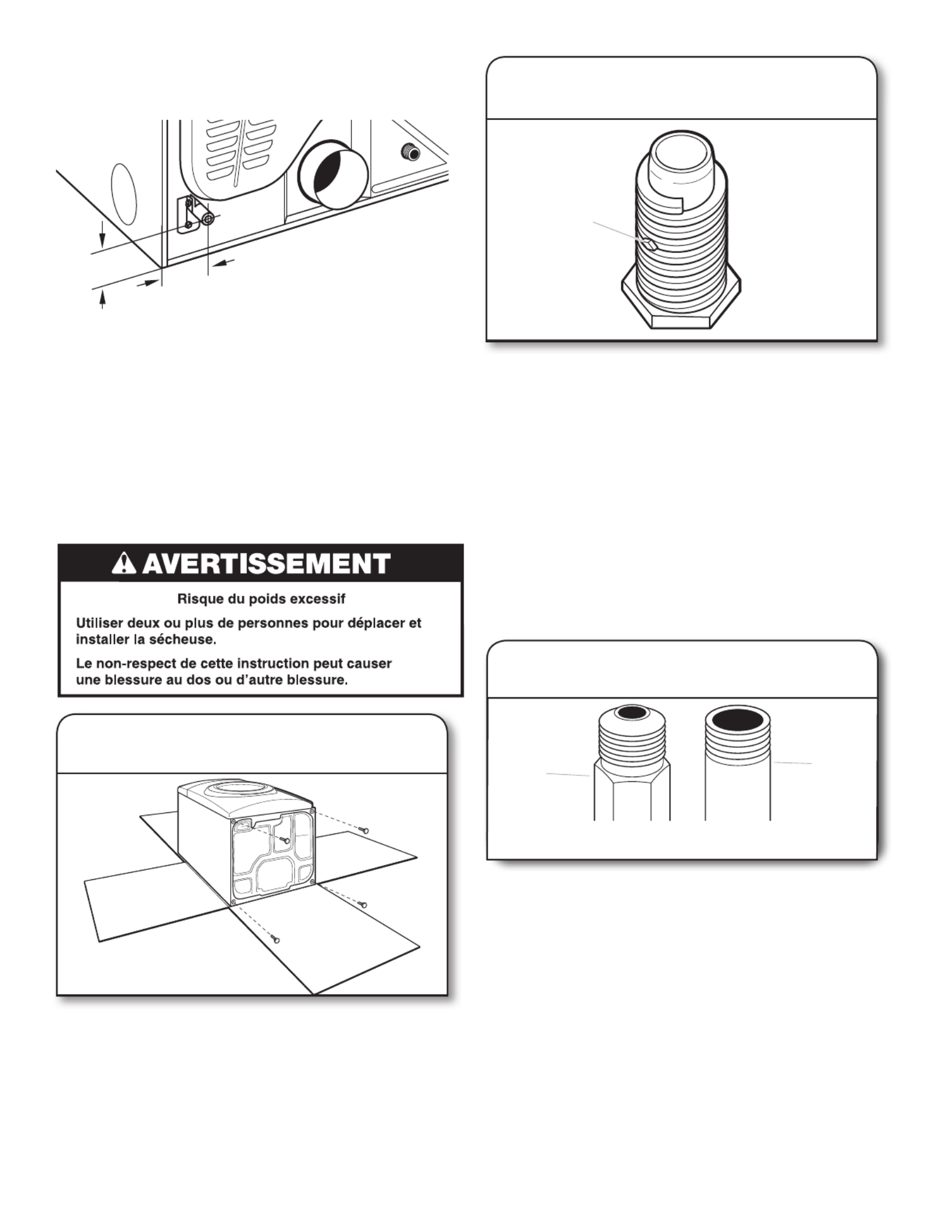
30
*53/4"
(146 mm)
11
/2"
(38 mm)
Connecteur de gaz exible de 3/8"
CANALISATION D’ARRIVÉE DE GAZ DE LA SÉCHEUSE
■La canalisation d’arrivée de gaz sortant à l’arrière de la
sécheuse est dotée d’un letage mâle de 3/8".
RACCORDEMENT AU GAZ
(modèles de sécheuses à gaz
uniquement)
INSTALLATION DES PIEDS
DE NIVELLEMENT
Pour ne pas endommager le plancher, utiliser une grande
pièce de carton de l’emballage de la sécheuse; la placer
sous tout le bord arrière de la sécheuse. Saisir fermement la
sécheuse par la caisse (non par le panneau de commande)
et incliner soigneusement la sécheuse sur le carton.
Examiner les pieds de nivellement, trouver le symbole
de losange. Introduire manuellement les vis des pieds dans
les trous, utiliser une clé à molette pour visser les pieds
jusqu’à ce que le symbole de losange ne soit plus visible.
Placer une cornière de carton prise à partir de l’emballage
de la sécheuse sous chacun des deux coins arrière de la
sécheuse. Redresser la sécheuse. Faire glisser la sécheuse
sur les cornières jusqu’à ce qu’elle soit proche de son
emplacement nal. Laisser sufsamment d’espace pour
connecter le conduit d’évacuation.
1. Préparer la sécheuse pour les pieds
de nivellement
2. Visser dans les pieds
de nivellement
diamond
marking
A
B
Connecter l’alimentation en gaz
à la sécheuse
1.
Retirer le capuchon rouge de la canalisation d’arrivée de
gaz. À l’aide d’une clé pour serrer, raccorder l’alimentation
en gaz à la sécheuse. Utiliser un composé d’étanchéité des
tuyauteries sur tous les letages des raccords mâles non
coniques. Si on utilise un conduit métallique souple, veiller
à ce qu’il ne soit pas pincé.
REMARQUE : Pour les raccordements au gaz de propane
liquéé, il faut utiliser un composé d’étanchéité des
tuyauteries résistant à l’action du gaz de propane liquéé.
Ne pas utiliser de ruban TEFLON®.
A. Raccord mâle conique
B. Raccord mâle non conique
symbole
de losange
* REMARQUE : Si la sécheuse est montée sur un piédestal,
prévoir 10" (254 mm) ou 15,5" (394 mm) de plus à partir du
sol pour la hauteur de la canalisation d’arrivée de gaz, en
fonction du modèle de piédestal. Pour une installation dans
un garage, prévoir 18" (460 mm) de plus à partir du sol pour
la hauteur de la canalisation d’arrivée de gaz.

32
Clapet à persiennes
Clapet incliné
Clapet de type boîte
Clapets de décharge :
Styles recommandés :
■Terminer le conduit d’évacuation par un clapet d’évacuation
pour empêcher les rongeurs et insectes d’entrer dans
l’habitation.
■Doit se situer à au moins 12" (305 mm) au-dessus du sol ou
de tout objet susceptible d’obstruer l’évacuation (par exemple
eurs, roches, arbustes ou neige).
■Ne pas utiliser un clapet d’évacuation à fermeture magnétique.
Style acceptable :
Coudes :
■Les coudes à 45° permettent une meilleure circulation de l’air
que les coudes à 90°.
Brides de serrage :
■Utiliser des brides de serrages pour sceller tous les joints.
■Le conduit d’évacuation ne doit pas être connecté ou xé avec
des vis ou avec tout autre dispositif de serrage qui se prolonge
à l’intérieur du conduit et où la charpie risque de s’accrocher.
Ne pas utiliser de ruban adhésif pour conduit.
Une mauvaise évacuation de l'air peut causer de
l'humidité et une accumulation de charpie à l'intérieur de
la maison, ce qui peut provoquer :
Dommages par l'humidité aux boiseries, meubles, peinture,
papier-peint, tapis, etc.
Problèmes de nettoyage dans la maison et problèmes
de santé.
Bon Meilleur
Planication du système d’évacuation
Choisir un type de système d’évacuation
Installations d’évacuation recommandées :
A. Sécheuse
B Raccord coudé
C. Mur
D. Clapet d’évacuation
E. Brides
F. Conduit d’évacuation
métallique rigide ou souple
G. Longueur de conduit
d’évacuation nécessaire pour
le raccordement des coudes
H. Bouche de décharge
A
BC
D
E
F
B
G
H
■La longueur du conduit métallique d’évacuation souple utilisé
doit être prise en compte lors de la conception de l’ensemble
du circuit d’évacuation, tel qu’indiqué dans le “Tableau des
systèmes d’évacuation”.
REMARQUE : Lors de l’utilisation d’un système de décharge
existant, nettoyer et éliminer la charpie sur toute la longueur
du système et veiller à ce que le clapet d’évacuation ne soit
pas obstrué par une accumulation de charpie. Remplacer
tout conduit de plastique ou de feuille métallique par un
conduit métallique rigide ou exible. Examiner le “Tableau des
systèmes d’évacuation” et au besoin, apporter les modications
nécessaires au système d’évacuation pour atteindre le meilleur
rendement de séchage.

33
Installations d’evacuation facultatives:
Cette sécheuse peut être convertie pour évacuer par le côté
droit, le côté gauche ou par le bas. Si vous préférez, vous pouvez
contactez votre détaillant local pour convertir la sécheuse.
A. Installation avec acheminement standard du
conduit d’evacuation par l’arrière
B. Installation du conduit d’évacuation
par la gauche ou par la droite
C. Installation avec évacuation par le bas
A B C
Déterminer l’itinéraire d’acheminement du conduit :
■Choisir l’itinéraire d’acheminement vers l’extérieur qui sera
le plus direct et le plus rectiligne.
■Planier l’installation pour introduire le nombre minimal
de coudes et de changements de direction.
■Si des coudes ou changements de direction sont utilisés,
prévoir autant d’espace que possible.
■Plier le conduit graduellement pour éviter de le déformer.
■Utiliser le moins de changements de direction à 90° possible.
Déterminer la longueur du conduit et les coudes
nécessaires :
■Utiliser le “Tableau des systèmes d’évacuation” ci-dessous
pour déterminer le type de composants et les combinaisons
acceptables.
REMARQUE : Ne pas utiliser un conduit de longueur
supérieure à la valeur spéciée dans le “Tableau des
systèmes d’évacuation”.
Si la longueur du circuit est supérieure à la valeur spéciée
dans le tableau, on observera :
■ Une réduction de la longévité de la sécheuse.
■ Une réduction du rendement, avec temps de séchage
plus longs et une plus grande consommation d’énergie.
Dispositions spéciales pour les résidences mobiles :
Le système d’évacuation doit être solidement xé à une section
non combustible de la structure de la résidence mobile et ne doit
pas se terminer en dessous de celle-ci. Acheminer le conduit
d’évacuation vers l’extérieur.
Tableau des systèmes d’évacuation
Nombre de
coudes à 90°
Type de
conduit
d’évacuation
Clapets de
type boîte/à
persiennes
Clapets
inclinés
1
4
3
2
0Métallique
rigide
Métallique
rigide
Métallique
rigide
Métallique
rigide
Métallique
rigide
64 pi (20 m)
54 pi (16,5 m)
44 pi (13,4 m)
35 pi (10,7 m)
27 pi (8,2 m)
58 pi (17,7 m)
48 pi (14,6 m)
38 pi (11,6 m)
29 pi (8,8 m)
21 pi (6,4 m)
Le “Tableau des systèmes d’évacuation” fournit les exigences
d’évacuation qui vous aideront à atteindre la meilleure
performance de séchage.
REMARQUE: Les installations d’évacuation par le côté ou par
le bas comportent un changement de direction à 90° à l’intérieur
de la sécheuse. Pour déterminer la longueur maximale du
conduit, ajouter un changement de direction à 90° au tableau.

34
Installation du système d’évacuation
1. Installer le clapet d’évacuation
12" min.
(305 mm)
12" min.
(305 mm)
2. Raccorder le conduit d’évacuation
au clapet
Installer le clapet d’évacuation et utiliser un composé de
calfeutrage pour calfeutrer le côté extérieur de l’ouverture
murale autour du clapet d’évacuation.
Le conduit doit être placé par dessus le clapet d’évacuation.
Fixer ensemble le conduit et le clapet avec une bride de 4"
(102 mm). Acheminer le conduit jusqu’à l’emplacement de
la sécheuse en utilisant le chemin le plus rectiligne possible.
Éviter les changements de direction à 90º. Utiliser des brides
pour sceller tous les joints. Ne pas utiliser de ruban adhésif
pour conduit, de vis ou autres dispositifs de xation qui se
prolongeraient à l’intérieur du conduit pour xer le conduit
d’évacuation; ceux-ci pourraient retenir la charpie.
RACCORDEMENT DU TUYAU
D’ALIMENTATION (MODÈLE VAPEUR
UNIQUEMENT)
Pour les modèles sans vapeur, passer directement à la section
“Raccordement du conduit d’évacuation”.
La sécheuse doit être connectée au robinet d’eau froide à l’aide
des nouveaux tuyaux d’alimentation (non fournis). Ne pas utiliser
de tuyaux usagés.
REMARQUE : Remplacer les tuyaux d’arrivée d’eau après 5 ans
d’utilisation pour réduire le risque de défaillance intempestive.
Prendre note de la date d’installation ou de remplacement des
tuyaux d’arrivée d’eau, pour référence ultérieure.
Inspecter périodiquement les tuyaux et les remplacer en cas de
renement, de déformation, de coupure, d’usure ou si une fuite
se manifeste.
Fixer le tuyau court
et le raccord en “Y”
2.
Si l’espace le permet, xer l’embout femelle du connecteur en
“Y” au robinet d’eau froide. Voir gure A.
Si le connecteur en “Y” ne peut être xé directement au
robinet d’eau froide, on doit utiliser le tuyau court. Voir gure
B. See gure B. Fixer un tuyau court au robinet d’eau froide.
Visser complètement le raccord à la main pour qu’il soit scellé
au robinet. Puis xer le raccord en “Y” à l’extrémité mâle du
tuyau court. Visser complètement le raccord à la main pour
qu’il soit scellé au connecteur en “Y”.
Fig. A
1. Fermer l’eau froide; retirer et
remplacer le joint de caoutchouc
Arrêter le robinet d’eau froide et retirer le tuyau d’alimentation
de la laveuse.
Vérier que le joint de caoutchouc se trouve dans le raccord
en “Y”. Retirer l’ancien joint de caoutchouc du tuyau d’arrivée
d’eau et le remplacer par le nouveau joint de caoutchouc
fourni.
Fig. B
Produktspezifikationen
| Marke: | Maytag |
| Kategorie: | Wäschetrockner |
| Modell: | MGD6000AG |
Brauchst du Hilfe?
Wenn Sie Hilfe mit Maytag MGD6000AG benötigen, stellen Sie unten eine Frage und andere Benutzer werden Ihnen antworten
Bedienungsanleitung Wäschetrockner Maytag

16 Oktober 2024
14 Oktober 2024
8 Oktober 2024
8 Oktober 2024
7 Oktober 2024
6 September 2024
4 September 2024
24 August 2024
24 August 2024
24 August 2024
Bedienungsanleitung Wäschetrockner
- Wäschetrockner Sinbo
- Wäschetrockner Samsung
- Wäschetrockner Infiniton
- Wäschetrockner Emerio
- Wäschetrockner G3 Ferrari
- Wäschetrockner Coline
- Wäschetrockner Hanseatic
- Wäschetrockner Panasonic
- Wäschetrockner LG
- Wäschetrockner Adler
- Wäschetrockner Beper
- Wäschetrockner Camry
- Wäschetrockner Bosch
- Wäschetrockner AEG
- Wäschetrockner Asko
- Wäschetrockner Siemens
- Wäschetrockner Bauknecht
- Wäschetrockner Electrolux
- Wäschetrockner Fagor
- Wäschetrockner Gaggenau
- Wäschetrockner Gorenje
- Wäschetrockner Klarstein
- Wäschetrockner Koenic
- Wäschetrockner Miele
- Wäschetrockner Teka
- Wäschetrockner Whirlpool
- Wäschetrockner Bomann
- Wäschetrockner Essentiel B
- Wäschetrockner Listo
- Wäschetrockner OK
- Wäschetrockner Russell Hobbs
- Wäschetrockner Taurus
- Wäschetrockner Vox
- Wäschetrockner ECG
- Wäschetrockner Thomson
- Wäschetrockner Amica
- Wäschetrockner BEKO
- Wäschetrockner Blaupunkt
- Wäschetrockner Eldom
- Wäschetrockner Grundig
- Wäschetrockner Hotpoint
- Wäschetrockner Inventum
- Wäschetrockner Sharp
- Wäschetrockner Smeg
- Wäschetrockner AEG-Electrolux
- Wäschetrockner Ansonic
- Wäschetrockner Ardo
- Wäschetrockner Ariston
- Wäschetrockner Aspes
- Wäschetrockner Balay
- Wäschetrockner Blomberg
- Wäschetrockner Scandomestic
- Wäschetrockner Brandt
- Wäschetrockner Candy
- Wäschetrockner Castor
- Wäschetrockner Constructa
- Wäschetrockner Corberó
- Wäschetrockner Daewoo
- Wäschetrockner ELIN
- Wäschetrockner Eudora
- Wäschetrockner Eurotech
- Wäschetrockner Everglades
- Wäschetrockner Exquisit
- Wäschetrockner Mitsubishi
- Wäschetrockner GE
- Wäschetrockner Haier
- Wäschetrockner Hisense
- Wäschetrockner Hoover
- Wäschetrockner Hotpoint-Ariston
- Wäschetrockner Iberna
- Wäschetrockner Ignis
- Wäschetrockner Bartscher
- Wäschetrockner Indesit
- Wäschetrockner Juno
- Wäschetrockner Baumatic
- Wäschetrockner Kelvinator
- Wäschetrockner Midea
- Wäschetrockner Caple
- Wäschetrockner NABO
- Wäschetrockner Neff
- Wäschetrockner Nordmende
- Wäschetrockner EAS Electric
- Wäschetrockner Otsein-Hoover
- Wäschetrockner PKM
- Wäschetrockner Privileg
- Wäschetrockner Rex
- Wäschetrockner Rommer
- Wäschetrockner Salora
- Wäschetrockner ETNA
- Wäschetrockner Schulthess
- Wäschetrockner Frigidaire
- Wäschetrockner SIBIR
- Wäschetrockner Smart Brand
- Wäschetrockner Speed Queen
- Wäschetrockner Svan
- Wäschetrockner V-ZUG
- Wäschetrockner Vestfrost
- Wäschetrockner Zanker
- Wäschetrockner Zanussi
- Wäschetrockner Zanussi-Electrolux
- Wäschetrockner Zerowatt
- Wäschetrockner Pelgrim
- Wäschetrockner Philco
- Wäschetrockner Akai
- Wäschetrockner Altus
- Wäschetrockner Arçelik
- Wäschetrockner Continental Edison
- Wäschetrockner Hyundai
- Wäschetrockner Kernau
- Wäschetrockner Element
- Wäschetrockner Ufesa
- Wäschetrockner Remington
- Wäschetrockner Gemini
- Wäschetrockner Sichler
- Wäschetrockner Frilec
- Wäschetrockner Atlas
- Wäschetrockner Cleanmaxx
- Wäschetrockner Cylinda
- Wäschetrockner Elba
- Wäschetrockner Faure
- Wäschetrockner UPO
- Wäschetrockner Friac
- Wäschetrockner Thomas
- Wäschetrockner White Knight
- Wäschetrockner Logik
- Wäschetrockner Microstar
- Wäschetrockner Wasco
- Wäschetrockner Andis
- Wäschetrockner Bluesky
- Wäschetrockner Orima
- Wäschetrockner Proline
- Wäschetrockner Heylo
- Wäschetrockner Westinghouse
- Wäschetrockner Amana
- Wäschetrockner Arthur Martin-Electrolux
- Wäschetrockner Euromaid
- Wäschetrockner Galanz
- Wäschetrockner Gram
- Wäschetrockner Whiteline
- Wäschetrockner Vivax
- Wäschetrockner Profilo
- Wäschetrockner Sauber
- Wäschetrockner Kleenmaid
- Wäschetrockner Lamona
- Wäschetrockner Tricity Bendix
- Wäschetrockner Kogan
- Wäschetrockner Royal Sovereign
- Wäschetrockner Nordland
- Wäschetrockner Master
- Wäschetrockner Edy
- Wäschetrockner Hoover-Helkama
- Wäschetrockner New Pol
- Wäschetrockner Zenith
- Wäschetrockner Insignia
- Wäschetrockner Crosley
- Wäschetrockner Danby
- Wäschetrockner Vedette
- Wäschetrockner Ariston Thermo
- Wäschetrockner EasyMaxx
- Wäschetrockner RCA
- Wäschetrockner AYA
- Wäschetrockner Fisher & Paykel
- Wäschetrockner Esatto
- Wäschetrockner Orbegozo
- Wäschetrockner CDA
- Wäschetrockner General Electric
- Wäschetrockner Seiki
- Wäschetrockner Defy
- Wäschetrockner Electra
- Wäschetrockner Huebsch
- Wäschetrockner Jocel
- Wäschetrockner Kenmore
- Wäschetrockner Lavorwash
- Wäschetrockner Magic Chef
- Wäschetrockner Marynen
- Wäschetrockner Miele Professional
- Wäschetrockner Mistral
- Wäschetrockner Novamatic
- Wäschetrockner One Concept
- Wäschetrockner Protech
- Wäschetrockner Stirling
- Wäschetrockner T4223C
- Wäschetrockner Technika
- Wäschetrockner WLA
- Wäschetrockner Wascomat
- Wäschetrockner Avanti
- Wäschetrockner Kunft
- Wäschetrockner Becken
- Wäschetrockner Rinnai
- Wäschetrockner Winia
- Wäschetrockner Romo
- Wäschetrockner Dexter Laundry
- Wäschetrockner Creda
- Wäschetrockner Artusi
- Wäschetrockner Trieste
- Wäschetrockner Sôlt
- Wäschetrockner Equator
- Wäschetrockner Simpson
- Wäschetrockner Hiberg
- Wäschetrockner Icecool
- Wäschetrockner LERAN
- Wäschetrockner Bendix
- Wäschetrockner Summit
- Wäschetrockner IFB
- Wäschetrockner Mabe
- Wäschetrockner Euro Appliances
- Wäschetrockner Amba
- Wäschetrockner Wisberg
- Wäschetrockner Alluxe
- Wäschetrockner John Lewis
- Wäschetrockner KDK
- Wäschetrockner Ormond
- Wäschetrockner TESLA Electronics
- Wäschetrockner Mybeo
Neueste Bedienungsanleitung für -Kategorien-

16 Oktober 2024

16 Oktober 2024

16 Oktober 2024

16 Oktober 2024

16 Oktober 2024

16 Oktober 2024
16 Oktober 2024
16 Oktober 2024
16 Oktober 2024

15 Oktober 2024