Lenovo ThinkCentre M720s Bedienungsanleitung
Lesen Sie kostenlos die 📖 deutsche Bedienungsanleitung für Lenovo ThinkCentre M720s (96 Seiten) in der Kategorie Desktop. Dieser Bedienungsanleitung war für 13 Personen hilfreich und wurde von 2 Benutzern mit durchschnittlich 4.5 Sternen bewertet
Seite 1/96

User Guid e
Types 6490, 8700, 8701, 8705
Types 8717, 8973, 8975, 8979
Types 8983, 8985, 8991, 8995
Types 9265, 9269, 9277, 9279
Types 9283, 9287, 9379, 9383
Types 9387, 9389, 9631, 9635
Types 9637, 9646, 9648, 9694


User Guid e

Note
Before using this information and the product it supports, be sure to read the“Important safety information” on page v and
Appendix B, “Notices,” on page 71.
Fourth Edition (February 2007)
© Copyright Lenovo 2006, 2007.
Portions © Copyright International Business Machines Corporation 2005.
All rights reserved.
U.S. GOVERNMENT USERS – RESTRICTED RIGHTS: Our products and/or services are provided with
RESTRICTED RIGHTS. Use, duplication or disclosure by the Government is subject to the GSA ADP Schedule
contract with Lenovo Group Limited, if any, or the standard terms of this commercial license, or if the agency is
unable to accept this Program under these terms, then we provide this Program under the provisions set forth in
Commercial Computer Software–Restricted Rights at 52.227-19, when applicable, or under Rights in FAR
Data-General, 52.227.14 (Alternate III). FAR

Contents
Important safety information . . . . . . v
Conditions that require immediate action. . . . . v
General safety guidelines . . . . . . . . . . vi
Service and upgrades . . . . . . . . . . vi
Static electricity prevention . . . . . . . . vii
Power cords and power adapters . . . . . . vii
Voltage-selection switch . . . . . . . . . viii
Extension cords and related devices . . . . . ix
Plugs and outlets . . . . . . . . . . . ix
External devices . . . . . . . . . . . . ix
Batteries . . . . . . . . . . . . . . ix
Heat and product ventilation . . . . . . . . x
Operating environment . . . . . . . . . xi
Electrical current safety information . . . . . . xi
Lithium battery notice . . . . . . . . . . . xii
Modem safety information . . . . . . . . . xii
Laser compliance statement. . . . . . . . . xiii
Power supply statement . . . . . . . . . . xiii
Products with television tuner options installed . . xiii
Note to CATV system installer. . . . . . . xiv
Example of antenna grounding . . . . . . xiv
Data safety . . . . . . . . . . . . . . xv
Cleaning and maintenance . . . . . . . . . xv
Using headphones or earphones . . . . . . . xv
Additional safety information . . . . . . . . xvi
Introduction . . . . . . . . . . . . xvii
Chapter 1. Arranging your workspace . . 1
Comfort . . . . . . . . . . . . . . . . 1
Glare and lighting . . . . . . . . . . . . 2
Air circulation . . . . . . . . . . . . . . 2
Electrical outlets and cable lengths . . . . . . . 2
Chapter 2. Setting up your computer . . 3
Connecting your computer . . . . . . . . . 3
Turning on power . . . . . . . . . . . . 8
Finishing the software installation . . . . . . . 8
Completing important tasks . . . . . . . . . 9
Updating your operating system. . . . . . . . 9
Installing other operating systems . . . . . . . 9
Updating your antivirus software . . . . . . . 9
Shutting down the computer . . . . . . . . . 9
Chapter 3. Installing options . . . . . 11
Features . . . . . . . . . . . . . . . 11
Specifications . . . . . . . . . . . . . . 14
Available options . . . . . . . . . . . . 15
Tools required . . . . . . . . . . . . . 15
Handling static-sensitive devices . . . . . . . 16
Installing external options . . . . . . . . . 16
Locating the connectors on the front of your
computer . . . . . . . . . . . . . . 17
Locating the connectors on the rear of your
computer . . . . . . . . . . . . . . 18
Obtaining device drivers . . . . . . . . . 19
Removing the cover . . . . . . . . . . . 20
Locating components . . . . . . . . . . . 21
Identifying parts on the system board . . . . . 22
Installing memory . . . . . . . . . . . . 25
Installing adapters . . . . . . . . . . . . 26
Installing internal drives . . . . . . . . . . 28
Drive specifications . . . . . . . . . . 28
Installing a drive in bay 1 or bay 2 . . . . . 30
Connecting drives . . . . . . . . . . . . 32
Connecting the first optical drive . . . . . . 32
Connecting an additional optical drive, or
parallel hard disk drive. . . . . . . ATA . 32
Connecting a serial hard disk drive. . . ATA . 33
Installing security features . . . . . . . . . 33
Integrated cable lock . . . . . . . . . . 34
Padlock. . . . . . . . . . . . . . . 35
Password protection . . . . . . . . . . 35
Changing the battery . . . . . . . . . . . 35
Erasing a lost or forgotten password (clearing
CMOS) . . . . . . . . . . . . . . . . 36
Replacing the cover and connecting the cables . . . 37
Chapter 4. Recovering software . . . . 39
Creating and using the Product Recovery disc . . . 39
Performing backup and recovery operations . . . 40
Using the Rescue and Recovery workspace . . . . 41
Creating and using rescue media . . . . . . . 42
Creating and using a Recovery Repair diskette . . 43
Recovering or installing devic e drivers . . . . . 44
Setting a rescue device in the startup sequence . . 45
Solving recovery problems . . . . . . . . . 45
Chapter 5. Using the Setup Utility . . . 47
Starting the Setup Utility program. . . . . . . 47
Viewing and changing settings . . . . . . . . 47
Using passwords . . . . . . . . . . . . 47
Password considerations . . . . . . . . . 47
User Password . . . . . . . . . . . . 48
Administrator Password . . . . . . . . . 48
Setting, c hanging, and deleting a password. . . 48
Using Security Profile by Device . . . . . . . 48
Selec ting a startup de vice. . . . . . . . . . 49
Selec ting a temporary startup device . . . . . 49
Changing the startup device sequence . . . . 49
Advanced settings . . . . . . . . . . . . 50
Exiting from the Setup Utility program . . . . . 50
Chapter 6. Updating system programs 51
Using system programs . . . . . . . . . . 51
Updating (flashing) BIOS from a diskette . . . . 51
© Lenovo 2006, 2007. Portions © IBM Corp. 2005. iii

Chapter 7. Troubleshooting and
diagnostics . . . . . . . . . . . . . 53
Basic troubleshooting . . . . . . . . . . . 53
Diagnostic programs . . . . . . . . . . . 54
PC-Doctor for Windows . . . . . . . . . 55
PC-Doctor for DOS . . . . . . . . . . . 55
PC-Doctor for Windows PE . . . . . . . . 57
Cleaning the mouse . . . . . . . . . . . 57
Optical mouse . . . . . . . . . . . . 57
Non-optical mouse . . . . . . . . . . . 57
Chapter 8. Getting information, help,
and service . . . . . . . . . . . . . 59
Information resources . . . . . . . . . . . 59
Online Books folder . . . . . . . . . . 59
ThinkVantage Productivity Center . . . . . . 59
Access Help . . . . . . . . . . . . . 60
Safety and warranty . . . . . . . . . . 60
www.lenovo.com . . . . . . . . . . . 60
Help and service . . . . . . . . . . . . 60
Using the documentation and diagnostic
programs . . . . . . . . . . . . . . 61
Calling for service . . . . . . . . . . . 61
Using other services . . . . . . . . . . 62
Purchasing additional services . . . . . . . 62
Appendix A. Manual modem
commands............ . 63
Basic commands . . . . . . . . . . AT . 63
Extended commands . . . . . . . . . AT . 65
MNP/V.42/V.42bis/V.44 commands . . . . . . 66
Fax Class 1 commands . . . . . . . . . . 67
Fax Class 2 commands . . . . . . . . . . 67
Voice commands. . . . . . . . . . . . . 68
Appendix B. Notices . . . . . . . . . 71
Television output notice . . . . . . . . . . 72
Trademarks . . . . . . . . . . . . . . 72
Index.............. . 73
iv User Guide

Important safety information
Note
Please read important safety information first.
This information can help you safely use your desktop or notebook personal
computer. Follow and retain all information included with your computer. The
information in this document does not alter the terms of your purchase agreement
or the Lenovo
™
Limited Warranty. For more information, refer to the safety and
warranty information that is provided with your computer..
Customer safety is important. Our products are developed to be safe and effective.
However, personal computers are electronic devices. Power cords, power adapters,
and other features can create potential safety risks that can result in physical injury
or property damage, especially if misused. reduce these risks, follow the To
instructions included with your product, observe all warnings on the product and
in the operating instructions, and review the information included in this
document carefully. By carefully following the information contained in this
document and provided with your product, you can help protect yourself from
hazards and create a safer computer work environment.
Note: This information includes references to power adapters and batteries. In
addition to notebook computers, some products (such as speakers and
monitors) ship with external power adapters. If you have such a product,
this information applies to your product. In addition, computer products
contain a coin-sized internal battery that provides power to the system clock
even when the computer is unplugged, so the battery safety information
applies to all computer products.
Conditions that require immediate action
Products can become damaged due to misuse or neglect. Some product damage
is serious enough that the product should not be used again until it has been
inspected and, if necessary, repaired by an authorized servicer.
As with any electronic device, pay close attention to the product when it is
turned on. On very rare occasions, you might notice an odor or see a puff of
smoke or sparks vent from your product. Or you might hear sounds like
popping, cracking, or hissing. These conditions might merely mean that an
internal electronic component has failed in a safe and controlled manner. Or,
they might indicate a potential safety issue. However, do not take risks or
attempt to diagnose the situation yourself. Contact the Customer Support Center
for further guidance. For a list of Service and Support phone numbers, see refer
to the safety and warranty information that is provided with your computer.
Frequently inspect your computer and its components for damage, wear, or signs
of danger. If you have any question about the condition of a component, do not
use the product. Contact the Customer Support Center or the product
manufacturer for instructions on how to inspect the product and have it
repaired, if necessary.
© Lenovo 2006, 2007. Portions © IBM Corp. 2005. v

In the unlikely event that you notice any of the following conditions, or if you
have any safety concerns with your product, stop using the product and unplug
it from the power source and telecommunication lines until you can speak to the
Customer Support Center for further guidance. See Chapter 8, “Getting
information, help, and service,” on page 59.
v Power cords, plugs, power adapters, extension cords, surge protectors, or power
supplies that are cracked, broken, or damaged.
v Signs of overheating, smoke, sparks, or fire.
v Damage to a battery (such as cracks, dents, or creases), discharge from a battery,
or a buildup of foreign substances on the battery.
v A cracking, hissing, or popping sound, or strong odor that comes from the
product.
v Signs that liquid has been spilled or an object has fallen onto the computer
product, the power cord, or power adapter.
v The computer product, power cord, or power adapter has been exposed to
water.
v The product has been dropped or damaged in any way.
v The product does not operate normally when you follow the operating
instructions.
Note: If you notice these conditions with a product (such as an extension cord)
that is not manufactured for or by Lenovo, stop using that product until you
can contact the product manufacturer for further instructions, or until you
get a suitable replacement.
General safety guidelines
Always observe the following precautions to reduce the risk of injury and property
damage.
Service and upgrades
Do not attempt to service a product yourself unless instructed to do so by the
Customer Support Center or your documentation. Only use a service provider who
is approved to repair your particular product.
Note: Some computer parts can be upgraded or replaced by the customer.
Upgrades typically are referred to as options. Replacement parts approved
for customer installation are referred to as Customer Replaceable Units, or
CRUs. Lenovo provides documentation with instructions when it is
appropriate for customers to install options or replace CRUs. must You
closely follow all instructions when installing or replacing parts. The Off
state of a power indicator does not necessarily mean that voltage levels
inside a product are zero. Before you remove the covers from a product
equipped with an ac power cord, always make sure that the power is turned
off and that the product is unplugged from any power source. For more
information on CRUs, refer to the User Guide for this product. If you have
any questions or concerns, contact the Customer Support Center.
Although there are no moving parts in your computer after the power cord has
been disconnected, the following warnings are required for your safety.
vi User Guide

Danger
Hazardous moving parts. Keep fingers and other body parts away.
Attention
Before replacing any CRUs, turn off the computer and wait three to five
minutes to let the computer cool before opening the cover.
Static electricity prevention
Static electricity, although harmless to you, can seriously damage computer
components and options. Improper handling of static-sensitive parts can cause
damage to the part. When you unpack an option or CRU, do not open the
static-protective package containing the part until the instructions direct you to
install it.
When you handle options or CRUs, or perform any work inside the computer, take
the following precautions to avoid static-electricity damage:
v Limit your movement. Movement can cause static electricity to build up around
you.
v Always handle components carefully. Handle adapters, memory modules, and
other circuit boards by the edges. Never touch exposed circuitry.
v Prevent others from touching components.
v When you install a static-sensitive option or CRU, touch the static-protective
package containing the part to a metal expansion-slot cover or other unpainted
metal surface on the computer for at least two seconds. This reduces static
electricity in the package and your body.
v When possible, remove the static-sensitive part from the static-protective
packaging and install the part without setting it down. When this is not
possible, place the static-protective packaging on a smooth, level surface and
place the part on it.
v Do not place the part on the computer cover or other metal surface.
Power cords and power adapters
Use only the power cords and power adapters supplied by the product
manufacturer.
Important safety information vii

The power cords shall be safety approved. For Germany, it shall be H05VV-F, 3G,
0.75 mm
2
, or better. For other countries, the suitable types shall be used
accordingly.
Never wrap a power cord around a power adapter or other object. Doing so can
stress the cord in ways that can cause the cord to fray, crack, or crimp. This can
present a safety hazard.
Always route power cords so that they will not be walked on, tripped over, or
pinched by objects.
Protect power cord and power adapters from liquids. For instance, do not leave
your power cord or power adapter near sinks, tubs, toilets, or on floors that are
cleaned with liquid cleansers. Liquids can cause a short circuit, particularly if the
power cord or power adapter has been stressed by misuse. Liquids also can cause
gradual corrosion of power cord terminals and/or the connector terminals on a
power adapter, which can eventually result in overheating.
Always connect power cords and signal cables in the correct order and ensure that
all power cord connectors are securely and completely plugged into receptacles.
Do not use any power adapter that shows corrosion at the ac input pins or shows
signs of overheating (such as deformed plastic) at the ac input or anywhere on the
power adapter.
Do not use any power cords where the electrical contacts on either end show signs
of corrosion or overheating or where the power cord appears to have been
damaged in any way.
Voltage-selection switch
Some computers are equipped with a voltage-selection switch located near the
power-cord connection point on the computer. If your computer has a
voltage-selection switch, ensure that you set the switch to match the voltage
available at your electrical outlet. Setting the voltage-selection switch incorrectly
can cause permanent damage to the computer.
If your computer does not have a voltage-selection switch, your computer is
designed to operate only at the voltage provided in the country or region where
the computer was originally purchased.
If you relocate your computer to another country, be aware of the following:
v If your computer does not have a voltage-selection switch, do not connect the
computer to an electrical outlet until you have verified that the voltage provided
is the same as it was in the country or region where the computer was originally
purchased.
v If your computer has a voltage selection switch, do not connect the computer to
an electrical outlet until you have verified that the voltage-selection switch is set
to match the voltage provided in that country or region.
If you are not sure of the voltage provided at your electrical outlet, contact your
local electric company or refer to official sites or other literature for travelers Web
to the country or region where you are located.
viii User Guide

Extension cords and related devices
Ensure that extension cords, surge protectors, uninterruptible power supplies, and
power strips that you use are rated to handle the electrical requirements of the
product. Never overload these devices. If power strips are used, the load should
not exceed the power strip input rating. Consult an electrician for more
information if you have questions about power loads, power requirements, and
input ratings.
Plugs and outlets
If a receptacle (power outlet) that you intend to use with your computer
equipment appears to be damaged or corroded, do not use the outlet until it is
replaced by a qualified electrician.
Do not bend or modify the plug. If the plug is damaged, contact the manufacturer
to obtain a replacement.
Do not share an electrical outlet with other home or commercial appliances that
draw large amounts of electricity; otherwise, unstable voltage might damage your
computer, data, or attached devices.
Some products are equipped with a three-pronged plug. This plug fits only into a
grounded electrical outlet. This is a safety feature. Do not defeat this safety feature
by trying to insert it into a non-grounded outlet. If you cannot insert the plug into
the outlet, contact an electrician for an approved outlet adapter or to replace the
outlet with one that enables this safety feature. Never overload an electrical outlet.
The overall system load should not exceed 80 percent of the branch circuit rating.
Consult an electrician for more information if you have questions about power
loads and branch circuit ratings.
Be sure that the power outlet you are using is properly wired, easily accessible,
and located close to the equipment. Do not fully extend power cords in a way that
will stress the cords.
Be sure that the power outlet provides the correct voltage and current for the
product you are installing.
Carefully connect and disconnect the equipment from the electrical outlet.
External devices
Do not connect or disconnect any external device cables other than USB and 1394
cables while the computer power is on; otherwise, you might damage your
computer. avoid possible damage to attached devices, wait at least five seconds To
after the computer is shut down to disconnect external devices.
Batteries
All personal computers manufactured by Lenovo contain a non-rechargeable coin
cell battery to provide power to the system clock. In addition, many mobile
products, such as notebook computers, utilize a rechargeable battery pack to
provide system power when in portable mode. Batteries supplied by Lenovo for
use with your product have been tested for compatibility and should only be
replaced with approved parts.
Important safety information ix

Never attempt to open or service any battery. Do not crush, puncture, or incinerate
batteries or short circuit the metal contacts. Do not expose the battery to water or
other liquids. Only recharge the battery pack strictly according to instructions
included in the product documentation.
Battery abuse or mishandling can cause the battery to overheat, which can cause
gasses or flame to “vent” from the battery pack or coin cell. If your battery is
damaged, or if you notice any discharge from your battery or the buildup of
foreign materials on the battery leads, stop using the battery and obtain a
replacement from the battery manufacturer.
Batteries can degrade when they are left unused for long periods of time. For some
rechargeable batteries (particularly Lithium Ion batteries), leaving a battery unused
in a discharged state could increase the risk of a battery short circuit, which could
shorten the life of the battery and can also pose a safety hazard. Do not let
rechargeable Lithium-Ion batteries completely discharge or store these batteries in a
discharged state.
Heat and product ventilation
Computers, AC adapters, and many accessories can generate heat when turned on
and when batteries are charging. Always follow these basic precautions:
v Do not leave your computer, AC adapter, or accessories in contact with your lap
or any part of your body for an extended period when the products are
functioning or when the battery is charging. Your computer, AC adapter, and
many accessories produce some heat during normal operation. Extended contact
with the body could cause discomfort or, potentially, a skin burn.
v Do not charge the battery or operate your computer, AC adapter, or accessories
near flammable materials or in explosive environments.
v Ventilation slots, fans, and heat sinks are provided with the product for safety,
comfort, and reliable operation. These features might inadvertently become
blocked by placing the product on a bed, sofa, carpet, or other flexible surface.
Never block, cover, or disable these features.
Inspect your desktop computer for dust accumulation at least once every three
months. Before inspecting your computer, turn off the power and unplug the
computer’s power cord from the electrical outlet; then remove any dust from vents
and perforations in the bezel. If you notice external dust accumulation, then
examine and remove dust from the inside of the computer including heat sink inlet
fins, power supply vents, and fans. Always turn off and unplug the computer
before opening the cover. If possible, avoid operating your computer within 2 feet
of high-traffic areas. If you must operate your computer in or near a high-traffic
area, inspect and, if necessary, clean your computer more frequently.
For your safety and to maintain optimum computer performance, always follow
these basic precautions with your desktop computer:
v Keep the cover closed whenever the computer is plugged in.
v Regularly inspect the outside of the computer for dust accumulation.
v Remove dust from vents and any perforations in the bezel. More frequent
cleanings might be required for computers in dusty or high-traffic areas.
v Do not restrict or block any ventilation openings.
v Do not store or operate your computer inside furniture, as this might increase
the risk of overheating.
v Airflow temperatures into the computer should not exceed 35° C (95° F).
x User Guide

v Do not use non-desktop air filtration devices.
Operating environment
The optimal environment in which to use your computer is 10°C-35°C (50°F-95°F)
with humidity ranging between 35% and 80%. If your computer is stored or
transported in temperatures less than 10°C (50°F), allow the cold computer to rise
slowly to an optimal operating temperature of 10°C-35°C (50°F-95°F) before use.
This process could take two hours in extreme conditions. Failure to allow your
computer to rise to an optimal operating temperature before use could result in
irreparable damage to your computer.
If possible, place your computer in a well-ventilated and dry area without direct
exposure to sunshine.
Keep electrical appliances such as an electric fan, radio, high-powered speakers, air
conditioner, and microwave oven away from your computer because the strong
magnetic fields generated by these appliances can damage the monitor and data on
the hard disk drive.
Do not place any beverages on top of or beside the computer or other attached
devices. If liquid is spilled on or in the computer or an attached device, a short
circuit or other damage might occur.
Do not eat or smoke over your keyboard. Particles that fall into your keyboard can
cause damage.
Electrical current safety information
Danger
Electrical current from power, telephone, and communication cables is
hazardous.
To avoid a shock hazard:
v To prevent possible shock hazard, do not use your computer during a
lightning storm.
v Do not connect or disconnect any cables or perform installation, maintenance,
or reconfiguration of this product during an electrical storm.
v Connect all power cords to a properly wired and grounded electrical outlet.
v Connect to properly wired outlets any equipment that will be attached to this
product.
v When possible, use one hand only to connect or disconnect signal cables.
v Never turn on any equipment when there is evidence of fire, water, or
structural damage.
v Disconnect the attached power cords, telecommunications systems, networks,
and modems before you open the device covers, unless instructed otherwise
in the installation and configuration procedures.
v Connect and disconnect cables as described in the following table when
installing, moving, or opening covers on this product or attached devices.
Important safety information xi

To connect:
1. Turn everything OFF.
2. First, attach all cables to devices.
3. Attach signal cables to connectors.
4. Attach power cords to outlet.
5. Turn device ON.
To disconnect:
1. Turn everything OFF.
2. First, remove power cords from outlet.
3. Remove signal cables from connectors.
4. Remove all cables from devices.
Lithium battery notice
Caution
Danger of explosion if battery is incorrectly replaced.
When replacing the lithium coin cell battery, use only the same or an equivalent
type that is recommended by the manufacturer. The battery contains lithium and
can explode if not properly used, handled, or disposed of.
Do not:
v Throw or immerse into water
v Heat to more than 100°C (212°F)
v Repair or disassemble
Dispose of the battery as required by local ordinances or regulations.
The following statement applies to users in the state of California, U.S.A.
Perchlorate material: Special handling may apply. See
www.dtsc.ca.gov/hazardouswaste/perchlorate.
Modem safety information
Caution
To reduce the risk of fire, use only No. 26 or larger AWG
telecommunication line cord.
To reduce the risk of fire, electrical shock, or injury when using telephone
equipment, always follow basic safety precautions, such as:
v Never install telephone wiring during a lightning storm.
v Never install telephone jacks in wet locations unless the jack is specifically
designed for wet locations.
v Never touch uninsulated telephone wires or terminals unless the telephone line
has been disconnected at the network interface.
v Use caution when installing or modifying telephone lines.
v Avoid using a telephone (other than a cordless type) during an electrical storm.
There may be a remote risk of electric shock from lightning.
v Do not use the telephone to report a gas leak in the vicinity of the leak.
xii User Guide

Laser compliance statement
Some personal computer models are equipped from the factory with a CD or DVD
drive. CD and DVD drives are also sold separately as options. CD and DVD drives
are laser products. These drives are certified in the U.S. to conform to the
requirements of the Department of Health and Human Services 21 Code of Federal
Regulations (DHHS 21 CFR) Subchapter J for Class 1 laser products. Elsewhere,
these drives are certified to conform to the requirements of the International
Electrotechnical Commission (IEC) 60825-1 and CENELEC EN 60 825-1 for Class 1
laser products.
When a CD or DVD drive is installed, note the following handling instructions.
Caution
Use of controls or adjustments or performance of procedures other than
those specified herein might result in hazardous radiation exposure.
Do not remove the drive covers. Removing the covers of the CD or DVD drive
could result in exposure to hazardous laser radiation. There are no serviceable
parts inside the CD or DVD drive.
Some CD and DVD drives contain an embedded Class 3A or Class 3B laser diode.
Note the following statement.
Danger
Laser radiation when open. Do not stare into the beam, do not view
directly with optical instruments, and avoid direct exposure to the beam.
Power supply statement
Never remove the cover on a power supply or any part that has the following
label attached.
Hazardous voltage, current, and energy levels are present inside any component
that has this label attached. There are no serviceable parts inside these components.
If you suspect a problem with one of these parts, contact a service technician.
Products with television tuner options installed
The notice below applies to products containing television (TV) tuner devices that
connect to external antennas or to cable/CATV systems, or both, and that are
intended to be installed in North America. Users and installers in other countries
should follow local codes and ordinances when installing appliances that connect
to external antennas and cable/CATV systems. If local codes are not applicable, it
is recommended that users/installers follow guidelines similar to those that follow.
Important safety information xiii
Note to CATV system installer
This reminder is provided to call the CATV system installer's attention to Article
820-40 of the National Electrical Code (NEC) that provides guidelines for proper
grounding and, in particular, specifies that the cable ground shall be connected to
the grounding system of the building, as close as possible to the point of cable
entry as practical.
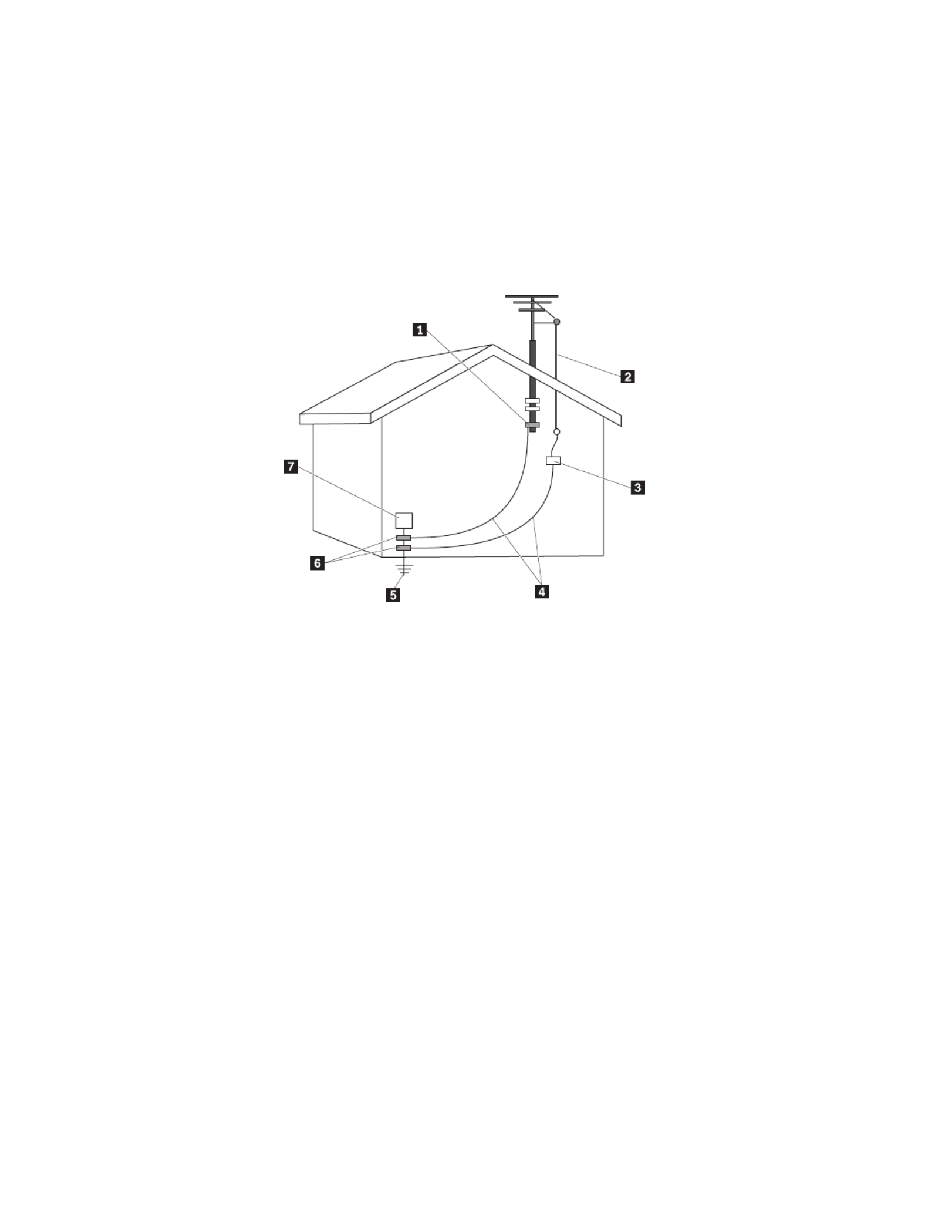
Example of antenna grounding
1 5 Ground clamp Power service grounding electrode system (NEC
Article 250, Part H)
2 6 Antenna lead-in wire Ground clamps
3 Antenna discharge unit (NEC
Section 810-20)
7 Electronic service equipment
4 Grounding conductors (NEC
Section 810-21
Figure 1. Proper grounding for the cable
xiv User Guide

The following notice applies to all countries and regions:
Danger
Outdoor antenna grounding
If an outside antenna or cable system is connected to the
equipment, be sure the antenna or cable system is grounded as to
provide some protection against voltage surges and built-up static
charges.
Lightning
For added protection for this equipment during a lightning storm,
or when it is left unattended and unused for long periods of time,
unplug it from the wall outlet and disconnect the antenna or cable
system. This will prevent damage to the video product due to
lightning and power line surges.
Power lines
An outside antenna system should not be located in the vicinity of
overhead power lines or where it can fall into such power lines or
circuits. When installing an outside antenna system, extreme care
should be taken to keep from touching such power lines or circuits,
as contact with them may be fatal.
Data safety
Do not delete unknown files or change the name of files or directories that were
not created by you; otherwise, your computer software might fail to work.
Be aware that accessing network resources can leave your computer vulnerable to
computer viruses, hackers, spyware, and other malicious activities that might
damage your computer, software, or data. It is your responsibility to ensure that
you have adequate protection in the form of firewalls, antivirus software, and
anti-spyware software and keep this software up to date.
Cleaning and maintenance
Keep your computer and workspace clean. Shut down the computer and then
disconnect the power cord before cleaning the computer. Do not spray any liquid
detergent directly on the computer or use any detergent containing flammable
material to clean the computer. Spray the detergent on a soft cloth and then wipe
the computer surfaces.
Using headphones or earphones
If your computer has both a headphone connector and an audio-out connector,
always use the headphone connector for headphones (also called a headset) or
earphones.
Excessive use of headphones or earphones for a long period of time at high
volume can be dangerous if the headphones or earphones do not comply with
specifications of EN 50332-2. The headphone output connector of your computer
Important safety information xv

complies with EN 50332-2 Sub clause 5.1. This specification limits the computer’s
maximum wide band true RMS output voltage to 150mV. help protect against To
hearing loss, ensure that the headphones or earphones you use also comply with
EN 50332-2 (Sub clause 6.1) for a wide band characteristic voltage of 75mV. Using
headphones that do not comply with EN 50332-2 can be dangerous due to
excessive sound pressure levels.
If your Lenovo computer came with headphones or earphones in the package, as a
set, the combination of the headphones or earphones and the computer already
complies with the specifications of EN 50332-1. If different headphones or
earphones are used, ensure that they comply with EN 50332-2. (Sub clause 6.1) for
a wide band characteristic voltage of 75mV. Using headphones that do not comply
with EN 50332-2 can be dangerous due to excessive sound pressure levels.
Additional safety information
Plastic bags can be dangerous. Keep plastic bags away from babies and children to
avoid danger of suffocation.
xvi User Guide

Introduction
This contains the following information: User Guide
v Chapter 1, “Arranging your workspace,” on page 1 provides information about
setting up your computer for comfort and the impact of light sources, air
circulation, and electrical outlets.
v Chapter 2, “Setting up your computer,” on page 3 provides information about
setting up your computer and software and operating system installation.
v Chapter 3, “Installing options,” on page provides information on the features 11
and options that are available for your computer.
v Chapter 4, “Recovering software,” on page 39 provides instructions on how to
use the ThinkVantage
®
Rescue and Recovery
™
program to create product
recovery disks, back up data, recover software, and restore the entire contents of
your hard disk to a previously saved state.
v Chapter 5, “Using the Setup Utility,” on page 47 provides instructions on how to
view and change the configuration settings of your computer.
v Chapter 6, “Updating system programs,” on page 51 provides information about
updating POST/BIOS and how to recover from a POST/BIOS update failure.
v Chapter 7, “Troubleshooting and diagnostics,” on page 53 provides information
about basic troubleshooting and diagnostic tools for your computer.
v Chapter 8, “Getting information, help, and service,” on page 59 provides
information about the wide variety of helpful resources available from Lenovo.
v Appendix A, “Manual modem commands,” on page 63 provides commands for
manually programming your modem.
v Appendix B, “Notices,” on page 71 provides notices and trademark information.
© Lenovo 2006, 2007. Portions © IBM Corp. 2005. xvii

xviii User Guide

Chapter 1. Arranging your workspace
To get the most from your computer, arrange both the equipment you use and
your work area to suit your needs and the kind of work you do. Your comfort is of
foremost importance, but light sources, air circulation, and the location of electrical
outlets also can affect the way you arrange your workspace.
Comfort
Although no single working position is ideal for everyone, here are a few
guidelines to help you find a position that suits you best.
Sitting in the same position for a long time can cause fatigue. A good chair can
make a big difference. The backrest and seat should adjust independently and
provide good support. The seat should have a curved front to relieve pressure on
the thighs. Adjust the seat so that your thighs are parallel to the floor and your
feet are either flat on the floor or on a footrest.
When using the keyboard, keep your forearms parallel to the floor and your wrists
in a neutral, comfortable position. to keep a light touch on the keyboard and Try
your hands and fingers relaxed. can change the angle of the keyboard for You
maximum comfort by adjusting the position of the keyboard feet.
Viewing Distance
Lower
Back
Support
Seat
Height
Adjust the monitor so the top of the screen is at, or slightly below, eye level. Place
the monitor at a comfortable viewing distance, usually 51 to 61 cm (20 to 24 in.),
and position it so you can view it without having to twist your body. Also position
other equipment you use regularly, such as the telephone or a mouse, within easy
reach.
© Lenovo 2006, 2007. Portions © IBM Corp. 2005. 1

Glare and lighting
Position the monitor to minimize glare and reflections from overhead lights,
windows, and other light sources. Even reflected light from shiny surfaces can
cause annoying reflections on your monitor screen. Place the monitor at right
angles to windows and other light sources, when possible. Reduce overhead
lighting, if necessary, by turning off lights or using lower wattage bulbs. If you
install the monitor near a window, use curtains or blinds to block the sunlight. You
might have to adjust the brightness and contrast controls on the monitor as the
room lighting changes throughout the day.
Where it is impossible to avoid reflections or to adjust the lighting, an antiglare
filter placed over the screen might be helpful. However, these filters might affect
the clarity of the image on the screen; try them only after you have exhausted
other methods of reducing glare.
Dust buildup compounds problems associated with glare. Remember to clean your
monitor screen periodically using a soft cloth moistened with a nonabrasive liquid
glass cleaner.
Air circulation
Your computer and monitor produce heat. The computer has a fan that pulls in
fresh air and forces out hot air. The monitor lets hot air escape through vents.
Blocking the air vents can cause overheating, which might result in a malfunction
or damage. Place the computer and monitor so that nothing blocks the air vents;
usually, 51 mm (2 in.) of air space is sufficient. Also, make sure the vented air is
not blowing on someone else.
Electrical outlets and cable lengths
The location of electrical outlets and the length of power cords and cables that
connect to the monitor, printer, and other devices might determine the final
placement of your computer.
When arranging your workspace:
v Avoid the use of extension cords. When possible, plug the computer power cord
directly into an electrical outlet.
v Keep power cords and cables neatly routed away from walkways and other
areas where they might get kicked accidentally.
For more information about power cords, see “Power cords and power adapters”
on page vii and the safety and warranty information that is provided with your
computer.
2 User Guide

Chapter 2. Setting up your computer
Before you begin, make sure you set up your computer in the best possible work
area that suits your needs and the kind of work you do. For more information,
refer to Chapter 1, “Arranging your workspace,” on page 1.
Note: Read “Important safety information” on page v“Important safety
information” on page v before you set up your computer. The precautions
and guidelines will help you work safely.
Connecting your computer
Use the following information when connecting your computer. Look for the small
connector icons on the back of your computer.
Important
Setting the voltage-selection switch incorrectly can cause permanent damage
to the computer.
If you are not sure of the voltage provided at your electrical outlet, contact
your local electric company or refer to official sites or other literature for Web
travelers to the country or region where you are located.
Note: Your computer might not have all of the switches or connectors described in
this section.
If your computer cables and connector panel have color-coded connectors, match
the color of the cable end with the color of the connector. For example, match a
blue cable end with a blue connector or a cable end with a connector. red red
1. Some models are equipped with a voltage-selection switch located near the
power-cord connection point on the computer.
If your computer has a voltage-selection switch, ensure that you set the
voltage-selection switch to match the voltage available at your electrical outlet.
If necessary, use a ballpoint pen to slide the switch to a different position.
v If the voltage supply range in your local country or region is 100–127 V ac,
set the switch to 115 V.
v If the voltage supply range is in your local country or region is 200–240 V
ac, set the switch to 230 V.
115
© Lenovo 2006, 2007. Portions © IBM Corp. 2005. 3

If your computer does not have a voltage selection switch, it is designed to
operate only at the voltage provided in the country or region where it was
originally purchased. Continue with step 2.
2. Your keyboard cable might have a standard keyboard connector or a 1
Universal Serial Bus (USB) connector . Connect the keyboard cable to the 2
appropriate keyboard connector.
Note: Some models will have keyboards with a fingerprint reader. After you
setup and turn on your computer, refer to the Access Help online help
system for information about your fingerprint reader. See “Access
Help” on page 60 for instructions on how to open the online help
system.
3. Your mouse cable might have a standard mouse connector or a USB 1
connector . Connect the mouse cable to the appropriate mouse connector. 2
4. Connect the monitor cable to the monitor connector on the computer.
v If you have a Video Graphics Array (VGA) Standard monitor, connect the
cable to the connector as shown.
Note: If your model has two monitor connectors, be sure to use the
connector on the accelerated graphics port (AGP) adapter.
4 User Guide

6. If you have audio devices, attach them using the following instructions. For
more information about speakers, see steps 7 and 8 on page 7.
1 Audio line-in This connector receives audio signals from an external audio device,
such as a stereo system.
2 Audio line-out This connector sends audio signals from the computer to external
devices, such as powered stereo speakers.
3 Microphone Use this connector to attach a microphone to your computer when
you want to record sound or if you use speech-recognition software.
4 Headphone Use this connector to attach headphones to your computer when you
want to listen to music or other sounds without disturbing anyone.
This connector might be located on the front of the computer.
7. If you have powered speakers with an ac adapter, use the following
instructions.
a. Connect the cable that runs between the speakers, if necessary. On some
speakers, this cable is permanently attached.
b. Connect the ac adapter cable to the speaker.
c. Connect the speakers to the computer.
d. Connect the ac adapter to the ac power source.
6 User Guide

10. Connect the power cords to properly grounded electrical outlets.
Note: Refer to the Access Help online help system for more information about
connectors. See “Access Help” on page 60 for instructions on how to open
the online help system.
Turning on power
Turn on the monitor and other external devices first, and then turn on the
computer. When the power-on self-test (POST) is finished, the logo window closes.
If your computer has preinstalled software, the software installation program
starts.
If you experience any problems during startup, see Chapter 7, “Troubleshooting
and diagnostics,” on page 53. For additional help, refer to Chapter 8, “Getting
information, help, and service,” on page 59. can get help and information by You
telephone through the Customer Support Center. Refer to the safety and warranty
information that is provided with your computer for the Service and Support
worldwide telephone list.
Finishing the software installation
Important
Read the license agreements carefully before using the programs on this
computer. These agreements detail your rights, obligations, and warranties for
the software on this computer. By using these programs, you accept the terms
of the agreements. If you do not accept the agreements, do not use the
programs. Instead, promptly return the entire computer for a full refund.
After you start the computer for the first time, follow the instructions on the screen
to complete the software installation. If you do not complete the software
installation the first time the computer is turned on, unpredictable results might
occur. When the installation is complete, refer to the Access Help online help
system to learn more about your computer. See “Access Help” on page 60 for
instructions on how to open the online help system.
Note: Some models might have a multilingual version of the Microsoft
®
Windows
®
operating system preinstalled. If your computer has the
multilingual version, you will be prompted to choose a language during the
initial installation process. After installation, the language version can be
changed through the Windows Control Panel.
8 User Guide

Completing important tasks
After you have set up your computer, perform the following tasks, which will save
you time and trouble later:
v Create a diagnostic CD image, diagnostic diskettes, or rescue media. Diagnostic
programs are used to test hardware components of your computer and report
operating-system-controlled settings that can cause hardware failures. Making a
diagnostic CD image, diagnostic diskettes, or rescue media ahead of time assures
that you will be able to diagnostics if the Rescue and Recovery workspace run
becomes inaccessible. For more information, see “PC-Doctor for DOS” on page
55 or “PC-Doctor for Windows PE” on page 57.
v Record your computer machine type, model, and serial number. If you need
service or technical support, you will probably be asked for this information. For
further information, see the safety and warranty information that is provided
with your computer.
Updating your operating system
Microsoft makes updates available for various operating systems through the
Microsoft Windows Update site. The site automatically determines what Web Web
Windows updates are available for your specific computer and lists those updates
only. Updates could include security fixes, new versions of Windows components
(such as media player), fixes to other portions of the Windows operating system,
or enhancements.
Refer to the Access Help online help system for more information about updating
your operating system. See “Access Help” on page 60 for instructions on how to
open the online help system.
Installing other operating systems
If you install your own operating system, follow the instructions that come with
your operating system CDs or diskettes. Remember to install all device drivers
after you install your operating system. Installation instructions are usually
provided with the device drivers.
Updating your antivirus software
Your computer comes with antivirus software you can use to detect and eliminate
viruses. Lenovo provides a full version of antivirus software on your hard disk
with a free 90-day subscription. After 90 days, you must get a new virus definition.
Refer to the Access Help online help system for more information about updating
your antivirus software. See “Access Help” on page 60 for instructions on how to
open the online help system.
Shutting down the computer
When you are ready to turn off your computer, always follow the shutdown
procedure for your operating system. This prevents the loss of unsaved data or
damage to your software programs. shut down the Microsoft Windows To
operating system, open the Start menu from the Windows desktop, click Shut
Down. S Shut Down OK elect from the drop down menu and click .
Chapter 2. Setting up your computer 9

Chapter 3. Installing options
This chapter provides an introduction to the features and options that are available
for your computer. can expand the capabilities of your computer by adding You
memory, adapters, or drives. When installing an option, use these instructions
along with the instructions that come with the option.
Note: Use only parts provided by Lenovo.
Important
Before you install or remove any option, read “Important safety information”
on page v. These precautions and guidelines will help you work safely.
Features
This section provides an overview of the computer features and preinstalled
software.
System information
The following information covers a variety of models. For information for
your specific model, refer to the Setup Utility program. See Chapter 5, “Using
the Setup Utility,” on page 47.
Microprocessor (varies by model type)
v Intel
®
Pentium
®
D processor
v Intel Pentium 4 processor with HyperThreading Technology
© Lenovo 2006, 2007. Portions © IBM Corp. 2005. 11

v Intel Pentium 4 processor
v Intel Celeron
®
D processor
v AMD Athlon 64
v AMD Sempron
v Internal cache (size varies by model type)
Memory
v Support for two double data rate 2 (DDR2) dual inline memory modules
(DIMMs)
v 512 KB flash memory for system programs
Internal drives
v 3.5-inch, slim, 1.44 MB diskette drive
v Serial Advanced Technology Attachment internal hard disk drive (SATA)
v Optical drive (some models)
Video subsystem
PCI Express x16 graphics adapter connector on the system board
Audio subsystem
v High-definition ADI 1986 Audio Codec
v Microphone and headphone connectors on the front panel
v Line in, line out, and microphone in connectors on the rear panel
v Mono internal speaker (some models)
Connectivity
v 10/100 Mbps integrated Ethernet controller that support for the Wake on LAN
®
feature (some models)
v 10/100/1000 Mbps integrated Ethernet controller (some models)
v PCI V.90 Data/Fax modem (some models)
System management features
v Remote Program Load (RPL) and Dynamic Host Configuration Protocol (DHCP)
v Wake on LAN
v Wake on Ring (in the Setup Utility program, this feature is called Serial Port
Ring Detect for an external modem)
v Remote Administration
v Automatic power-on startup
v System Management (SM) BIOS and SM software
v Ability to store power-on self-test (POST) hardware test results
Input/output features
v 25-pin, Extended Capabilities Port (ECP)/Extended Parallel Port (EPP)
v 9-pin serial connector
v Six 4-pin, USB connectors (two on front panel and four on rear panel)
v Standard mouse connector
v Standard keyboard connector
v Ethernet connector
12 User Guide

v VGA monitor connector
v Audio connectors (see Audio subsystem)
Expansion
v Four drive bays
v Two standard PCI adapter connectors
v One PCI Express x1 adapter connector
v One PCI Express x16 graphics adapter connector (some models)
Power
v 250 Watt power supply with manual voltage selection switch (some models)
v 280 Watt power supply with manual voltage selection switch (some models)
v 310 Watt power supply with manual voltage selection switch (some models)
v Automatic 50/60 Hz input frequency switching
v Advanced Configuration and Power Interface (ACPI) support
Security features
v Keyboard with fingerprint reader (some models, use the ThinkVantage
Productivity Center program to find more information)
v User and administrator passwords for BIOS access
v Support for the addition of an integrated cable lock (Kensington lock) to secure
the cover
v Support for the addition of a padlock to secure the cover
v Startup sequence control
v Startup without diskette drive, keyboard, or mouse
v Unattended start mode
v Diskette and hard disk I/O control
v Serial and parallel port I/O control
v Security profile by device
Preinstalled software
Your computer might come with preinstalled software. If it does, an operating
system, device drivers to support built-in features, and other support programs are
included.
Operating systems preinstalled (varies by model type)
Note: Not all countries or regions will have these operating systems.
v Microsoft Windows XP Home
v Microsoft Windows XP Professional
v Microsoft Windows Vista
™
Operating systems certified or tested for compatibility
1
v Microsoft Windows 2000
v Linux
®
1. The operating systems listed here are being certified or tested for compatibility at the time this publication goes to press.
Additional operating systems might be identified by Lenovo as compatible with your computer following the publication of this
booklet. Corrections and additions to this list are subject to change. determine if an operating system has been certified or To
tested for compatibility, check the site of the operating system vendor. Web
Chapter 3. Installing options 13

Specifications
This section lists the physical specifications for your computer.
Dimensions
Height: 400 mm (15.7 in.)
Width: 175 mm (6.9 in.)
Depth: 432 mm (17.0 in.)
Weight
Minimum configuration: 8.17 kg (18 lb)
Maximum configuration: 10.21 kg (22.5 lb)
Environment
Air temperature:
System on: 10° to 35°C (50° to 95° F)
System off: 10° to 60°C (50° to 140° F)
Maximum altitude: 914 m (3000 ft)
Note: The maximum altitude, 914 m (3000 ft), is the maximum altitude at which the specified air
temperatures apply. At higher altitudes, the maximum air temperatures are lower than those specified.
Humidity:
System on: 10% to 80%
System off: 10% to 90%
Electrical input: Some models have a switchable power supply that supports both low and high input voltage
ranges. Some models do not have a switch and support only a low or high input voltage range. See
“Voltage-selection switch” on page viii for additional information.
Input voltage:
Low range:
Minimum: 100 V ac
Maximum: 127 V ac
Input frequency: 50/60 Hz
Voltage switch setting: V ac (some models) 115
High range:
Minimum: 200 V ac
Maximum: 240 V ac
Input frequency: 50/60 Hz
Voltage switch setting: 230 V ac (some models)
Input kilovolt-amperes (kVA) (approximate):
Minimum configuration as shipped: 0.10 kVA
Maximum configuration: 0.31 kVA
14 User Guide

Available options
The following are some available options:
v External options
– Parallel port devices, such as printers and external drives
– Serial port devices, such as external modems and digital cameras
– Audio devices, such as external speakers for the sound system
– USB devices, such as printers, joysticks, and scanners
– Security device, such as a padlock
– Monitors
v
Internal options
– System memory, called dual inline memory modules (DIMMs)
– PCI adapters
– PCI Express x1 adapter
– PCI Express x16 adapter (some models)
– Internal drives, such as:
- Optical drives, such as CD and DVD drives
- Hard disk drive
- Diskette drives and other removable media drives
For the latest information about available options, see the Lenovo site at Web
http://www.lenovo.com or contact your reseller or marketing representative.
Tools required
To install some options in your computer, you might need a flat-blade or Phillips
screwdriver. Additional tools might be needed for certain options. See the
instructions that come with the option.
Chapter 3. Installing options 15

Handling static-sensitive devices
Static electricity, although harmless to you, can seriously damage computer
components and options.
When you add an option, do open the static-protective package containing the not
option until you are instructed to do so.
When you handle options and other computer components, take these precautions
to avoid static electricity damage:
v Limit your movement. Movement can cause static electricity to build up around
you.
v Always handle components carefully. Handle adapters and memory modules by
the edges. Never touch any exposed circuitry.
v Prevent others from touching components.
v When you install a new option, touch the static-protective package containing
the option to a metal expansion-slot cover or other unpainted metal surface on
the computer for at least two seconds. This reduces static electricity in the
package and your body.
v When possible, remove the option and install it directly in the computer without
setting the option down. When this is not possible, place the static-protective
package that the option came in on a smooth, level surface and place the option
on it.
v Do not place the option on the computer cover or other metal surface.
Installing external options
This section shows the various external connectors on your computer to which you
can attach external options, such as external speakers, a printer, or a scanner. For
some external options, you must install additional software in addition to making
the physical connection. When adding an external option, use the information in
this section to identify the required connector, and then use the instructions that
come with the option to help you make the connection and install any software or
device drivers that are required for the option.
16 User Guide
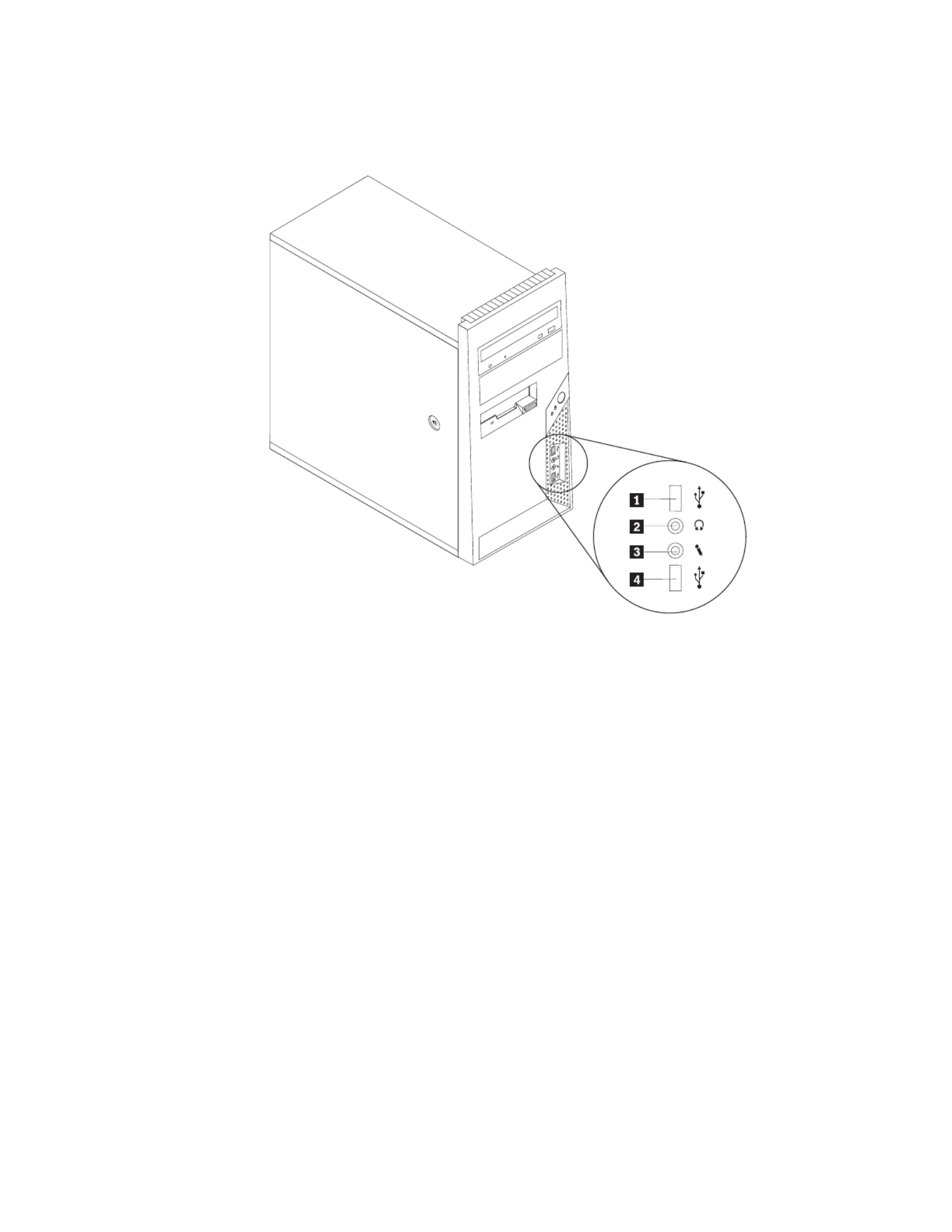
Locating the connectors on the front of your computer
The following illustration shows the locations of the connectors on the front of the
computer.
1 3 USB connector Microphone connector
2 4 Headphone connector USB connector
Chapter 3. Installing options 17

Locating the connectors on the rear of your computer
The following illustration shows the locations of the connectors on the rear of the
computer.
1 Power supply diagnostic
LEDs
10 Ethernet connector
2 Voltage selection switch
(some models)
11 USB connectors (2)
3 12 Power connector Microphone connector
4 13 Standard mouse connector Audio line out connector
5 Standard keyboard connector Audio line in connector 14
6 15 Serial connector PCI Express x1 or PCI Express x16 graphics
adapter connector
7 16 Parallel connector PCI Express x1 or PCI Express x16 graphics
adapter connector
8 17 VGA monitor connector PCI Adapter connector
9 USB connectors (2)
Note: Some connectors on the rear of the computer are color-coded to help you
determine where to connect the cables on your computer.
18 User Guide

Connector Description
Mouse connector Used to attach a mouse, trackball, or other pointing device that
uses a standard mouse connector.
Keyboard connector Used to attach a keyboard that uses a standard keyboard
connector.
Serial connector Used to attach an external modem, serial printer, or other
devices that use a 9-pin serial connector.
Parallel connector Used to attach a parallel printer, parallel scanner, or other
devices that use a 25-pin parallel connector.
USB connectors Used to attach a device that requires a Universal Serial Bus
(USB) connection, such as a USB scanner or USB printer. If you
have more than six USB devices, you can purchase a USB hub,
which you can use to connect additional USB devices.
Ethernet connector Used to attach an Ethernet cable for a local area network
(LAN).
Note: To operate the computer within FCC Class B limits, use
a Category 5 Ethernet cable.
Microphone connector Used to attach a microphone to your computer when you want
to record voice or other sounds on the hard disk if you use
speech-recognition software.
Audio line out connector Used to send audio signals from the computer to external
devices, such as powered stereo speakers (speakers with
built-in amplifiers), headphones, multimedia keyboards, or the
audio line in connector on a stereo system or other external
recording device.
Audio line in connector Used to receive audio signals from an external audio device,
such as a stereo system. When you attach an external audio
device, a cable is connected between the audio line out
connector of the device and the audio line in connector of the
computer.
Obtaining device drivers
You can obtain device drivers for operating systems that are not preinstalled at
http://www.lenovo.com/support/ on the World Wide Web. Installation
instructions are provided in README files with the device-driver files.
Chapter 3. Installing options 19

Locating components
The following illustration will help you locate the various components in your
computer.
1 Microprocessor fan and heat sink PCI Express and PCI adapter 4
connectors
2 5 Memory modules System fan
3 6 PCI adapter card Power supply
Chapter 3. Installing options 21

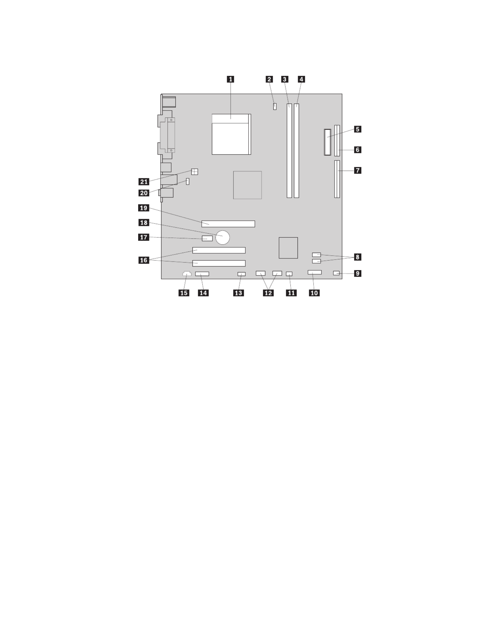
Identifying parts on the system board
The system board (sometimes called the or ) is the main circuit planar motherboard
board in your computer. It provides basic computer functions and supports a
variety of devices that are factory-installed or that you can install later.
The following illustration shows the locations of parts on the system board (some
models).
1 Microprocessor fan connector Front panel connector 12
2 Microprocessor and heat sink IDE connectors (2) 13 SATA
3 14 Memory connector 1 Front panel USB connectors (2)
4 15 Memory connector 2 SATA IDE connector (2)
5 16 Clear CMOS/Recovery jumper PCI adapter connectors
6 17 Power connector Front audio connector
7 18 Diskette drive connector CD-IN connector
8 19 IDE connector 1 PCI Express x16 graphics adapter
connector
9 20 IDE connector 2 PCI Express x1 adapter connector
10 21 Battery System fan connector
11 22 Power fan connector 12v power connector
22 User Guide
The following illustration shows the locations of parts on the system board (some
models).
1 Microprocessor and heat sink Front USB connectors (2) 12
2 Microprocessor fan connector Serial (COM) connector 13
3 14 Memory connector 1 Front audio connector
4 15 Memory connector 2 CD-IN connector
5 16 Power connector PCI adapter connectors (2)
6 17 Diskette drive connector PCI Express x1 adapter connector
7 18 IDE connector Battery
8 19 SATA IDE connectors (2) PCI Express x16 graphics adapter
connector
9 20 Power fan connector System fan connector
10 21 Front panel connector 12v power connector
11 Clear CMOS/Recovery jumper
Chapter 3. Installing options 23

The following illustration shows the locations of parts on the system board (some
models).
1 Microprocessor and heat sink Front panel connector 12
2 Microprocessor fan connector Front panel USB connectors (2) 13
3 14 Memory connector 1 Front audio connector
4 15 Memory connector 2 CD-IN connector
5 16 Diskette drive connector PCI adapter connectors
6 17 Power connector PCI Express x1 adapter connector
7 18 IDE connector 1 Battery
8 19 IDE connector 2 PCI Express x16 graphics adapter
connector
9 20 Power fan connector System fan connector
10 21 SATA IDE connector (2) 12v power connector
11 Clear CMOS/Recovery jumper
24 User Guide

Installing memory
Your computer has two connectors for installing dual inline memory modules
(DIMMs) that provide up to a maximum of 4.0 GB of system memory.
When installing memory modules, the following rules apply:
v Use 1.8 240-pin double data rate 2 synchronous dynamic random access V,
memory (DDR2 SDRAM).
v Use 256 MB, 512 MB, 1.0 GB, or 2.0 GB memory modules in any combination up
to a maximum of 4.0 GB.
To install a memory module:
1. Remove the computer cover. See “Removing the cover” on page 20.
2. Locate the memory connectors. See “Identifying parts on the system board” on
page 22.
3. Open the retaining clips.
4. Make sure that the notch 1 on the memory module aligns correctly with the
connector key on the system board. Push the memory module straight 2
down into the connector until the retaining clips close.
What to do next:
v To work with another option, go to the appropriate section.
v To complete the installation, go to “Replacing the cover and connecting the
cables” on page 37.
Chapter 3. Installing options 25
Installing adapters
This section provides information and instructions for installing and removing
adapters. Your computer has two expansion connectors for PCI adapters and one
for a PCI Express x1 adapter.
To install an adapter:
1. Remove the computer cover. See “Removing the cover” on page 20.
2. At the rear of the computer, press the release button to open the adapter 1
latch and remove the slot cover.2
3. Remove the adapter from its static-protective package.
4. Install the adapter into the appropriate connector on the system board.
26 User Guide

5. Pivot the adapter latch to the closed position to secure the adapters.
What to do next
v To work with another option, go to the appropriate section.
v To complete the installation, go to “Replacing the cover and connecting the
cables” on page 37.
Chapter 3. Installing options 27

Installing internal drives
This section provides information and instructions for installing and removing
internal drives.
Internal drives are devices that your computer uses to read and store data. can You
add drives to your computer to increase storage capacity and to enable your
computer to read other types of media. Some of the different drives that are
available for your computer are:
v Serial hard disk drives ATA
v Parallel hard disk drives ATA
v Optical drives, such as CD drives or DVD drives
v Removable media drives
Note: These different drives are also referred to as integrated drive electronics
(IDE) drives.
Internal drives are installed in . In this book, the bays are referred to as bay 1, bays
bay 2, and so on.
When you install an internal drive, it is important to note what type and size of
drive that you can install in each bay. Also, it is important to correctly connect the
internal drive cables to the installed drive.
Drive specifications
Your computer comes with the following factory-installed drives:
v An optical drive in bay 1 (some models)
v A 3.5-inch diskette disk drive in bay 3 (some models)
v A 3.5-inch hard drive in bay 4
Any bay that does not have a drive installed has a static shield and bay panel
installed.
28 User Guide

The following illustration shows the locations of the drive bays.
The following list describes the types and size of drives you can install in each
bay:
1Bay 1 - Maximum height: 43.0 mm (1.7 in.) Optical drive such as CD drive or DVD v
drive (preinstalled in some models)
v 5.25-inch hard disk drive
v 3.5-inch hard disk drive (requires a
Universal Adapter Bracket, 5.25 to
3.5-inch)*
2Bay 2 - Maximum height: 43.0 mm (1.7 in.) Optical drive such as CD drive or DVD v
drive
v 5.25-inch removable media drive
v 3.5-inch hard disk drive (requires a
Universal Adapter Bracket, 5.25 to
3.5-inch)*
3Bay 3 - Maximum height: 25.8 mm (1.0 in.) 3.5-inch diskette drive (some models
preinstalled)
4Bay 4 - Maximum height: 25.8 mm (1.0 in.) 3.5-inch hard disk drive SATA
(preinstalled)
5Bay 5 - Maximum height: 25.8 mm (1.0 in.) 3.5-inch hard disk drive SATA
* can obtain a Universal Adapter Bracket, 5.25 to 3.5-inch from a local You
computer retailer or by contacting the Customer Support Center.
Chapter 3. Installing options 29

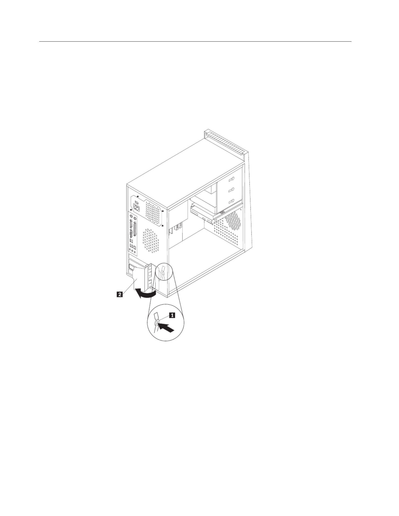
Installing a drive in bay 1 or bay 2
To install a drive in bay 1 or bay 2, follow these steps:
1. Remove the computer cover. See “Removing the cover” on page 20.
2. Remove the front bezel by releasing the three plastic tabs on the left side and
pivoting the bezel outward. Carefully set the bezel to the side without
disconnecting the power switch and LED assembly cable.
Note: Notice the spare retainer bracket attached to the side of the upper 1
drive cage.
3. Remove the metal static shield from the drive bay using your fingers to pull it
outward.
4. If you are installing a drive with accessible media, such as an optical drive,
remove the plastic panel in the bezel for bay 2 by squeezing the plastic tabs
that secure the panel on the inside of the bezel.
5. If you are installing any type of drive other than a serial ATA hard drive,
make sure the drive that you are installing is set correctly as either a master
or a slave device.
Note: A serial hard disk drive does not need to be set as either a master ATA
or a slave device.
If you are installing an optical drive or a parallel hard disk drive, set it as ATA
a master device. Refer to the documentation that comes with your drive for
master/slave jumper information.
6. Remove the retainer bracket from the upper driver cage by sliding it
downward.
30 User Guide

7. For a 5.25-inch drive, install a retainer bracket on the side of the drive.
8. For a 3.5-inch drive, you must use a Universal Adapter Bracket, 5.25 to
3.5-inch. can obtain a Universal Adapter Bracket, 5.25 to 3.5-inch from a You
local computer retailer or by contacting the Customer Support Center. Install a
retainer bracket on the side of the Universal adapter bracket.
9. Install the 5.25-inch drive or the adapter bracket and 3.5-inch drive into the
bay.
10. To reinstall the bezel, align the plastic tabs on the right side of the bezel with
the corresponding holes in the chassis, then pivot it inward until it snaps into
position on the left side.
11. Continue at “Connecting drives” on page 32.
Chapter 3. Installing options 31

Connecting drives
The steps to connect a drive are different depending on the type of drive. Use one
of the following procedures for your drive connection.
Connecting the first optical drive
1. The drive requires two cables; a power cable that connects to the power supply
and a signal cable that connects to the system board.
2. Locate the three-connector signal cable that comes with your computer or with
the new drive.
3. Locate the IDE connector on the system board. See “Identifying parts on the
system board” on page 22.
4. Connect one end of the signal cable to the drive and the other to the IDE
connector on the system board. reduce electronic noise, use the connectors at To
the end of the cable only.
5. Locate the extra four-wire power connector labelled P4 and connect it to the
drive.
Connecting an additional optical drive, or parallel hard ATA
disk drive
1. Locate the extra connector on the three-connector signal cable that is attached
to the IDE connector on the system board. See “Identifying parts on the system
board” on page 22.
2. Connect the extra connector on the signal cable to the new drive.
3. Locate the extra four-wire power connector and connect it to the drive.
32 User Guide

Connecting a serial hard disk drive ATA
A serial hard disk drive can be connected to any available connector. SATA
1. Locate the signal cable that comes with the new drive.
2. Locate an available SATA connector on the system board. See “Identifying parts
on the system board” on page 22.
3. Connect one end of the signal cable to the drive and the other to an available
SATA connector on the system board.
4. Locate one of the extra five-wire power connectors and connect it to the drive.
What to do next
v To work with another option, go to the appropriate section.
v To complete the installation, go to “Replacing the cover and connecting the
cables” on page 37.
Installing security features
To help prevent hardware theft and unauthorized access to your computer, several
security lock options are available. In addition to physical locks, unauthorized use
of your computer can be prevented by a software lock that locks the keyboard
until a correct password is typed in.
Make sure that any security cables you install do not interfere with other computer
cables.
Chapter 3. Installing options 33

Integrated cable lock
With an integrated cable lock (sometimes referred to as the Kensington lock), you
can secure your computer to a desk, table, or other non-permanent fixture. The
cable lock attaches to a security slot at the rear of your computer and is operated
with a key. The cable lock also locks the buttons used to open the computer cover.
This is the same type of lock used with many laptop computers. can order a You
security cable directly from Lenovo. Go to http://www.lenovo.com/support/ and
search on . Kensington
34 User Guide

To change the battery:
1. Turn off the computer and all attached devices.
2. Remove the computer cover. See “Removing the cover” on page 20.
3. Locate the battery. See “Identifying parts on the system board” on page 22.
4. Remove the old battery.
5. Install the new battery.
6. Replace the computer cover, and plug in the power cord. See “Replacing the
cover and connecting the cables” on page 37.
Note: When the computer is turned on for the first time after battery
replacement, an error message might be displayed. This is normal after
replacing the battery.
7. Turn on the computer and all attached devices.
8. Use the Setup Utility program to set the date and time and any passwords. See
Chapter 5, “Using the Setup Utility,” on page 47.
Erasing a lost or forgotten password (clearing CMOS)
This section applies to lost or forgotten passwords. For more information about
lost or forgotten passwords, see the ThinkVantage Productivity Center program on
your desktop.
To erase a forgotten password:
1. Turn off the computer and all attached devices.
2. Remove the computer cover. See “Removing the cover” on page 20.
3. Locate the Clear CMOS/Recovery jumper on the system board. See
“Identifying parts on the system board” on page 22.
4. Move the jumper from the standard position (pins 1 and 2) to the maintenance
or configure position (pins 2 and 3).
5. Replace the computer cover and connect the power cord. See “Replacing the
cover and connecting the cables” on page 37.
6. Restart the computer, leave it on for approximately ten seconds. Turn off the
computer by holding the power switch for approximately five seconds. The
computer will turn off.
7. Repeat steps 2 through 4 on page 36.
36 User Guide

8. Move the jumper back to the standard (pins 1 and 2).
9. Replace the computer cover and connect the power cord. See “Replacing the
cover and connecting the cables.”
Replacing the cover and connecting the cables
After working with options, you need to install any removed parts, replace the
computer cover, and reconnect any cables, including telephone lines and power
cords. Also, depending on the option that is installed, you might need to confirm
the updated information in the Setup Utility program.
To replace the computer cover and connect cables to your computer:
1. Ensure that all components have been reassembled correctly and that no tools
or loose screws are left inside your computer.
2. Clear any cables that might impede the replacement of the computer cover.
3. Position the computer cover on the chassis so that the rail guides on the bottom
of the cover engage the rails and push the cover closed until it latches.
4. Install any thumbscrews that were removed when removing the cover.
5. Install any cover locking devices as necessary.
6. Reconnect the external cables and power cords to the computer. See “Installing
external options” on page 16.
7. To update the configuration, see Chapter 5, “Using the Setup Utility,” on page
47.
Chapter 3. Installing options 37

38 User Guide

Chapter 4. Recovering software
There are a variety of methods to choose from when considering how to recover
software in the event of a software or hardware-related problem. Some methods
vary depending on the type of operating system you have.
This chapter will help you become familiar with recovery solutions provided by
Lenovo. This chapter explains how and when to use the following recovery
methods:
v Creating and using Product Recovery discs
v Performing backup and recovery operations
v Using the Rescue and Recovery workspace
v Creating and using rescue media
v Creating and using a Recovery Repair diskette
v Recovering or installing device drivers
v Setting a rescue device in the startup sequence
v Solving recovery problems
Refer to the Access Help online help system for additional information about the
Rescue and Recovery program provided by Lenovo. For information on how to
access the online help system, see “Access Help” on page 60.
Creating and using the Product Recovery disc
If your computer is equipped with a recordable CD or DVD drive, you can create a
set of Product Recovery discs that enables you to restore the contents of the hard
disk to the same state as when the computer was originally shipped from the
factory. Product Recovery discs are useful if you transfer the computer to another
area, sell the computer, recycle the computer, or as a last resort put the computer
in an operational state after all other methods of recovery have failed. As a
precautionary measure, it is important to create a set of Product Recovery discs as
soon as possible.
Note: The recovery operations you can perform using Product Recovery discs vary
depending on the operating system from which they were created. Your
Microsoft Windows license permits you to create only one set of Product
Recovery discs, so it is important that you store the discs in a safe place
after you make them.
To create Product Recovery discs, do the following:
1. From the Windows desktop, open the Start menu, select , select All Programs
ThinkVantage Create Recovery Media, click .
2. In the Recovery Discs section, select Create a set of Recovery Discs now.
3. Follow the instructions on the screen.
The following list explains how Product Recovery discs are used on different
operating systems:
v Windows XP: Use Product Recovery discs to restore your computer to the
original factory contents, perform a custom factory recovery, or to perform other
rescue and recovery operations such as rescuing individual files.
© Lenovo 2006, 2007. Portions © IBM Corp. 2005. 39
Produktspezifikationen
| Marke: | Lenovo |
| Kategorie: | Desktop |
| Modell: | ThinkCentre M720s |
Brauchst du Hilfe?
Wenn Sie Hilfe mit Lenovo ThinkCentre M720s benötigen, stellen Sie unten eine Frage und andere Benutzer werden Ihnen antworten
Bedienungsanleitung Desktop Lenovo

14 Oktober 2024
11 Oktober 2024
30 September 2024
24 September 2024
18 September 2024
11 September 2024
9 September 2024
25 August 2024
25 August 2024
25 August 2024
Bedienungsanleitung Desktop
- Desktop Samsung
- Desktop Acer
- Desktop Apple
- Desktop Asus
- Desktop BenQ
- Desktop Gigabyte
- Desktop HP
- Desktop Medion
- Desktop Microsoft
- Desktop Sharkoon
- Desktop Sony
- Desktop LG
- Desktop Sharp
- Desktop WOOOD
- Desktop Haier
- Desktop TrekStor
- Desktop Optoma
- Desktop PEAQ
- Desktop Toshiba
- Desktop Mio
- Desktop ViewSonic
- Desktop Dell
- Desktop LC-Power
- Desktop MSI
- Desktop JYSK
- Desktop Tripp Lite
- Desktop Razer
- Desktop ELO
- Desktop Targa
- Desktop Xoro
- Desktop Vtech
- Desktop Parisot
- Desktop Wehkamp
- Desktop Supermicro
- Desktop Faytech
- Desktop InFocus
- Desktop NEC
- Desktop Seagate
- Desktop Fujitsu
- Desktop Maxdata
- Desktop Packard Bell
- Desktop Kogan
- Desktop ZTE
- Desktop Atari
- Desktop Kramer
- Desktop Asrock
- Desktop ECS
- Desktop Promethean
- Desktop Vorago
- Desktop Emachines
- Desktop Ibm
- Desktop MP
- Desktop ONYX
- Desktop Alienware
- Desktop Zotac
- Desktop Intel
- Desktop Moxa
- Desktop VXL
- Desktop Planar
- Desktop Shuttle
- Desktop Altra
- Desktop Axis
- Desktop Advantech
- Desktop Elitegroup
- Desktop BDI
- Desktop Bestar
- Desktop Pelco
- Desktop Foxconn
- Desktop System76
- Desktop NComputing
- Desktop Cybernet
- Desktop Aopen
- Desktop Smart Things
- Desktop Zoostorm
- Desktop Dell Wyse
- Desktop MvixUSA
- Desktop AIS
- Desktop Wyse
Neueste Bedienungsanleitung für -Kategorien-

30 November 2024

15 Oktober 2024
12 Oktober 2024

9 Oktober 2024

9 Oktober 2024

7 Oktober 2024
4 Oktober 2024
4 Oktober 2024

4 Oktober 2024
3 Oktober 2024