JVC ProHD GY-HM600 Bedienungsanleitung
Lesen Sie kostenlos die 📖 deutsche Bedienungsanleitung für JVC ProHD GY-HM600 (136 Seiten) in der Kategorie Camcorder. Dieser Bedienungsanleitung war für 24 Personen hilfreich und wurde von 2 Benutzern mit durchschnittlich 4.5 Sternen bewertet
Seite 1/136

.
HD MEMORY CARD CAMERA RECORDER
GY-HM600U/GY-HM600E
INSTRUCTIONS
.
TIME CO DE
The specifications and appearance of this product are subject to changes for further improvement
without prior notice.
Please check the latest version of the INSTRUCTIONS from the following Mobile User Guide, or
download the PDF from the URL below.
Mobile User Guide
When you are outside, you can refer to the instructions from your Android phone or
iPhone.
http://manual3.jvckenwood.com/pro/mobile/global/
You can view the Mobile User Guide using the browser on your Android phone or
iPhone.
.
Thank you for purchasing this JVC product.
Before operating this unit, please read the
instructions carefully to ensure the best
possible performance.
In this manual, each model number is
described without the last letter (U/E) which
means the shipping destination.
(U: for USA and Canada, E: for Europe)
Only “U” models (GY-HM600U) have been
evaluated by UL.
Please read the following before getting started:
For Customer Use:
Model No. GY-HM600U
Serial No.
Enter below the Serial No. which is located
on the body.
Retain this information for future reference.
Ver. 3.00

.
1. Read these instructions.
2. Keep these instructions.
IMPORTANT SAFEGUARDS
4. Follow all instructions.
5.
Do not use this apparatus near water.
6. Clean only with dry cloth.
7.
Do not block any ventilation openings. Install in accordance with the manufacturer’s
instructions.
8. Do not install near any heat sources such as radiators, heat registers, stoves, or
other apparatus (including amplifiers) that produce heat.
These are general IMPORTANT SAFEGUARDS and certain items may not
apply to all appliances.
3. Heed all warnings.
FOR USA
9.
Protect the power cord from being walked on or pinched particularly at plugs,
convenience receptacles, and the point where they exit from the apparatus.
10. Only use attachments/accessories specified by the manufacturer.
11. Use only with the cart, stand, tripod, bracket, or table
specified by the manufacturer, or sold with the apparatus.
When a cart is used, use caution when moving the
cart/apparatus combination to avoid injury from tip-over.
12. Unplug this apparatus during lightning storms or when
unused for long periods of time.
13. Refer all servicing to qualified service personnel.
Servicing is required when the apparatus has been damaged in any way, such as
power-supply cord or plug is damaged, liquid has been spilled or objects have
fallen into the apparatus, the apparatus has been exposed to rain or moisture,
does not operate normally, or has been dropped.
INFORMATION (FOR CANADA)
RENSEIGNEMENT (POUR CANADA)
This Class A digital apparatus complies with Canadian ICES-003.
Cet appareil numérique de la classe A est conforme à la norme NMB-003 du Canada.
For USA-California Only
This product contains a CR Coin Cell Lithium Battery which contains Perchlorate
Material – special handling may apply.
See www.dtsc.ca.gov/hazardouswaste/perchlorate
2

Safety Precautions
.
CAUTION
FOR USA AND CANADA
CAUTION:
TO REDUCE THE RISK OF
ELECTRIC SHOCK.
DO NOT REMOVE COVER (OR
BACK).
NO USER-SERVICEABLE PARTS
INSIDE. REFER SERVICING TO
QUALIFIED SERVICE
PERSONNEL.
The lightning flash with
arrowhead symbol, within
an equilateral triangle is
intended to alert the user to
the presence of uninsulated
“dangerous voltage” within
the product’s enclosure that
may be of sufficient
magnitude to constitute a
risk of electric shock to
persons.
The exclamation point within
an equilateral triangle is
intended to alert the user to
the presence of important
operating and maintenance
(servicing) instructions in
the literature accompanying
the appliance.
RISK OF ELECTRIC
SHOCK
DO NOT OPEN
.
This device complies with Part 15 of
FCC Rules. Operation is subject to the
following two conditions: (1) This
device may not cause harmful
interference, and (2) this device must
accept any interference received,
including interference that may cause
undesired operation.
Changes or modifications not
approved by JVC could void the
user’s authority to operate the
equipment. This equipment has been
tested and found to comply with the
limits for a Class A digital device,
pursuant to Part 15 of the FCC Rules.
These limits are designed to provide
reasonable protection against harmful
interference when the equipment is
operated in a commercial
environment.
This equipment generates, uses, and
can radiate radio frequency energy
and, if not installed and used in
accordance with the instructions, may
cause harmful interference to radio
communications. Operation of this
equipment in a residential area is
likely to cause harmful interference in
which case the user will be required
to correct the interference at his own
expense.
3

.
POUR CANADA
RISQUE
D’ELECTROCUTION
NE PAS OUVRIR
CAUTION:
The mains plug shall remain readily
operable.
Remove the mains plug immediately if
the camera functions abnormally.
WARNING:
The battery pack, the camera with
battery installed, and the remote control
with battery installed should not be
exposed to excessive heat such as direct
sunlight, fire or the like.
ATTENTION:
POUR EVITER TOUT RISQUE
D’ELECTROCUTION NE PAS
OUVRIR LE BOITER. AUCUNE
PIECE INTERIEURE N’EST A
REGLER PAR L’UTILISATEUR. SE
REFERER A UN AGENT QUALIFIE
EN CAS DE PROBLEME.
ATTENTION
Le symbole de l’éclair à
l’intérieur d’un triangle
équilatéral est destiné à
alerter l’utilisateur sur la
présence d’une “tension
dangereuse” non isolée dans
le boîtier du produit. Cette
tension est suffisante pour
provoquer l’électrocution de
personnes.
Le point d’exclamation à
l’intérieur d’un triangle
équilatéral est destiné à
alerter l’utilisateur sur la
présence d’opérations
d’entretien importantes au
sujet desquelles des
renseignements se trouvent
dans le manuel
d’instructions.
Ces symboles ne sont
utilisés qu’aux Etats-Unis.
.
WARNING: TO PREVENT FIRE OR
SHOCK HAZARD, DO NOT
EXPOSE THIS UNIT TO RAIN OR
MOISTURE.
AVERTISSEMENT : POUR EVITER
LES RISQUES D’INCENDIE OU
D’ELECTROCUTION, NE PAS
EXPOSER L’APPAREIL A LA
PLUIE NI A L’HUMIDITE.
NOTES:
The rating plate and safety caution are
on the bottom and/or the back of the
main unit.
The serial number plate is on the
bottom of the unit.
The rating information and safety
caution of the AC adapter are on its
upper and lower sides.
REMARQUES :
La plaque d’identification et
l’avertissement de sécurité se trouvent
sous l’appareil et/ou au dos.
La plaque du numéro de série est
située sur la partie inférieure de
l’appareil.
Les informations d’identification et
l’avertissement de sécurité de
l’adaptateur secteur sont situés sur ses
côtés supérieur et inférieur.
Caution on Replaceable lithium
battery
The battery used in this device may
present a fire or chemical burn hazard if
mistreated.
Do not recharge, disassemble, heat
above 100°C (212°F) or incinerate.
Replace battery with Panasonic, Sanyo,
Sony or Maxell CR2025.
Danger of explosion or risk of fire if the
battery is incorrectly replaced.
Dispose of used battery promptly.
Keep away from children.
Do not disassemble and do not dispose
of in fire.
4
Introduction

.
When the equipment is installed in a
cabinet or on a shelf, make sure that it
has sufficient space on all sides to allow
for ventilation (10 cm (3-15/16 ) or more "
on both sides, on top and at the rear).
Do not block the ventilation holes.
(If the ventilation holes are blocked by a
newspaper, or cloth etc. the heat may not
be able to get out.)
No naked flame sources, such as lighted
candles, should be placed on the
apparatus.
When discarding batteries,
environmental problems must be
considered and the local rules or laws
governing the disposal of these batteries
must be followed strictly.
The apparatus shall not be exposed to
dripping or splashing.
Do not use this equipment in a bathroom
or places with water.
Also do not place any containers filled
with water or liquids (such as cosmetics
or medicines, flower vases, potted
plants, cups etc.) on top of this unit.
(If water or liquid is allowed to enter this
equipment, fire or electric shock may be
caused.)
Do not point the lens directly into the
sun. This can cause eye injuries, as well
as lead to the malfunctioning of internal
circuitry. There is also a risk of fire or
electric shock.
CAUTION!
The following notes concern possible
physical damage to this unit and to the
user.
Carrying or holding this unit by the LCD
monitor can result in dropping the unit,
or in a malfunction.
Do not use a tripod on unsteady or
unlevel surfaces. It could tip over,
causing serious damage to the unit.
CAUTION!
Connecting cables (Audio/Video, etc.) to
this unit and leaving it on top of the TV is
not recommended, as tripping on the
cables will cause the unit to fall, resulting
in damage.
.
When using the AC adapter in
areas other than the USA
The provided AC adapter features
automatic voltage selection in the AC
range from 110 V to 240 V.
USING HOUSEHOLD AC PLUG
ADAPTER
In case of connecting the unit’s power
cord to an AC wall outlet other than
American National Standard C73 series
type, use an AC plug adapter called a
“Siemens Plug” as shown.
For this AC plug adapter, consult your
nearest JVC dealer.
Remove the AC adapter from the AC
wall outlet when not in use.
Do not leave dust or metal objects
adhered to the AC wall outlet or AC
adapter (power/DC plug).
Plug Adapter
5
Introduction

.
IMPORTANT (for owners in the
U.K.)
Connection to the mains supply in
the United Kingdom.
DO NOT cut off the mains plug
from this equipment.
If the plug fitted is not suitable for the
power points in your home or the cable is
too short to reach a power point, then
obtain an appropriate safety approved
extension lead or consult your dealer.
BE SURE to replace the fuse only with
an identical approved type, as originally
fitted, and to replace the fuse cover.
If nonetheless the mains plug is cut off
be sure to remove the fuse and dispose
of the plug immediately, to avoid possible
shock hazard by inadvertent connection
to the mains supply.
If this product is not supplied fitted with a
mains plug then follow the instructions
given below:
DO NOT make any connection to the
Larger Terminal coded E or Green.
The wires in the mains lead are coloured
in accordance with the following code:
If these colours do not correspond with
the terminal identifications of your plug,
connect as follows:
Blue wire to terminal coded N (Neutral)
or coloured black.
Brown wire to terminal coded L (Live) or
coloured Red.
If in doubt consult a competent —
electrician.
CAUTIONS:
To prevent shock, do not open the
cabinet. No user serviceable parts
inside.
Refer servicing to qualified personnel.
When you are not using the AC
adapter for a long period of time, it is
recommended that you disconnect the
power cord from AC outlet.
Blue to N
(Neutral) or Black
Brown to L (Live)
or Red
.
Dear Customer,
This apparatus is in conformance with
the valid European directives and
standards regarding electromagnetic
compatibility and electrical safety.
European representative of
JVC KENWOOD Corporation is:
JVC Technical Services Europe GmbH
Postfach 10 05 04
61145 Friedberg
Germany
Sehr geehrter Kunde, sehr
geehrte Kundin,
dieses Gerät stimmt mit den gültigen
europäischen Richtlinien und Normen
bezüglich elektromagnetischer
Verträglichkeit und elektrischer
Sicherheit überein.
Die europäische Vertretung für die
JVC KENWOOD Corporation ist:
JVC Technical Services Europe GmbH
Postfach 10 05 04
61145 Friedberg
Deutschland
WARNING
This is a Class A product. In a domestic
environment this product may cause
radio interference in which case the user
may be required to take adequate
measures.
CAUTION:
To avoid electric
shock or damage to
the unit, first firmly
insert the small end
of the power cord into the AC Adapter
until it is no longer wobbly, and then plug
the larger end of the power cord in to an
AC outlet.
FOR EUROPEAN
6
Introduction

.
Information for Users on Disposal
of Old Equipment and Batteries
[European Union]
These symbols indicate that the electrical
and electronic equipment and the battery
with this symbol should not be disposed of
as general household waste at its
end-of-life.
Instead, the products should be handed
over to the applicable collection points for
the recycling of electrical and electronic
equipment as well as batteries for proper
treatment, recovery and recycling in
accordance with your national legislation
and the Directive 2002/96/EC and
2006/66/EC.
By disposing of these products correctly,
you will help to conserve natural resources
and will help to prevent potential negative
effects on the environment and human
health which could otherwise be caused by
inappropriate waste handling of these
products.
For more information about collection
points and recycling of these products,
please contact your local municipal office,
your household waste disposal service or
the shop where you purchased the
product.
Penalties may be applicable for incorrect
disposal of this waste, in accordance with
national legislation.
(Business users)
If you wish to dispose of this product,
please visit our web page
http://www.jvc.eu to obtain information
about the take-back of the product.
[Other Countries outside the
European Union]
These symbols are only valid in the
European Union.
If you wish to dispose of these items,
please do so in accordance with applicable
national legislation or other rules in your
country for the treatment of old electrical
and electronic equipment and batteries.
Products
Battery
The sign Pb below the
symbol for batteries indicates
that this battery contains lead.
Notice:
.
Battery Pack
The supplied battery pack is a lithium-ion
battery. Before using the supplied battery
pack or an optional battery pack, be sure
to read the following cautions:
To avoid hazards
... do not burn.
When transporting, carry the battery in
a plastic bag.
... do not modify or disassemble.
... do not expose the battery to
temperatures exceeding 60 C (140 F), ° °
as this may cause the battery to
overheat, explode or catch fire.
... use only specified chargers.
To prevent damage and prolong
service life
... do not subject to unnecessary shock.
... charge within the temperature range
of 10 C to 35 C (50 F to 95 F). Cooler ° ° ° °
temperatures require longer charging
time, or in some cases stop charging
at all. Warmer temperatures prevent
complete charging, or in some cases
stop charging at all.
... store in a cool, dry place. Extended
exposure to high temperatures will
increase natural discharge and
shorten service life.
... keep a 30% battery level if the
battery pack is not to be used for a
long period of time.
In addition, fully charge and then fully
discharge the battery pack every 6
months, then continue to store it at a
30% battery level .
... remove from charger or powered unit
when not in use, as some machines
use current even when switched off.
... do not drop or subject to strong
impact.
... do not short-circuit the
terminals. Keep it away
from metallic objects
when not in use.
Terminals
7
Introduction

Contents
Introduction
Safety Precautions ............................................ 3
Contents ............................................................ 8
Main Features ................................................. 10
Precautions for Proper Use ............................. 12
Operation Modes ............................................. 16
Names of Parts ................................................ 18
Side Control Panel ....................................... 20
SD Slot ......................................................... 21
Rear Terminal .............................................. 21
LCD Monitor ................................................ 22
Lens Section ................................................ 23
Basic System Diagram .................................... 24
Preparations
Settings and Adjustments Before Use ............. 25
Adjusting the Grip Belt ................................. 25
Attaching an External Microphone ............... 25
Attaching the Tripod ..................................... 25
Attaching the Large Eyecup ......................... 25
Opening/Closing the Lens Cover ................. 26
Attaching/Detaching the Hood ..................... 26
Power Supply .................................................. 26
Using a Battery Pack .................................... 26
Using AC Power (DC IN Power) ................... 28
Power Status Display ...................................... 28
Turning On/Off the Power ................................ 29
Initial Settings .................................................. 30
Displays on the LCD Monitor and Viewfinder .. 32
Display Screen ............................................. 32
Status Screen .............................................. 33
USB Mode Screen ....................................... 33
Warning Display ........................................... 33
Adjusting the LCD Monitor and Viewfinder ...... 34
Adjusting the LCD Monitor ........................... 34
Adjusting the Viewfinder .............................. 35
Assigning Functions to User Buttons ............... 36
Tally Lamp ....................................................... 36
SD Card ........................................................... 37
Usable Cards ............................................... 37
Formatting (Initializing) SD Cards ................ 39
Restoring the SD Card ................................. 40
Clips Recorded to SD Cards ........................ 41
Shooting
Basic Shooting Procedures ............................. 42
Selecting System Definition, File Format and Video
Format ............................................................. 43
Zoom Operation .............................................. 44
Focus Operation .............................................. 45
Adjusting the Focusing by Face Detection ...... 46
Adjusting the Brightness .................................. 48
Adjusting the Iris .............................................. 49
Setting the Gain ............................................... 50
Setting the Electronic Shutter .......................... 51
Setting the ND Filter ........................................ 53
Adjusting the White Balance ............................ 53
Adjusting the Camera Image ........................... 56
Using the Image Stabilizer ............................... 56
Audio Recording .............................................. 57
Monitoring Audio Sound During Recording Using a
Headphone ...................................................... 59
Time Code and User’s Bit ................................ 60
Setting Time Code Generator .......................... 61
Synchronizing Time Code on Another Camera
......................................................................... 64
Setting Zebra Pattern ...................................... 65
Setting Spot Meter ........................................... 66
Viewing Recorded Videos Immediately (Clip
Review) ........................................................... 68
Splitting the Clips Freely (Clip Cutter Trig) ....... 68
Dual Rec .......................................................... 69
Backup Rec ..................................................... 71
Special Recording ........................................... 73
Pre Rec ........................................................ 73
Clip Continuous Rec .................................... 73
Frame Rec ................................................... 75
Interval Rec .................................................. 76
Variable Frame Rec ..................................... 77
Playback
Playing Recorded Clips ................................... 78
Thumbnail Screen ........................................ 78
Actions ......................................................... 80
Playing back ................................................ 81
Deleting Clips .................................................. 82
Appending/Deleting OK Mark .......................... 83
Selecting and Performing Operations on Multiple
Clips ................................................................ 84
Selecting Multiple Clips Randomly ............... 84
Selecting Multiple Clips Consecutively ........ 84
Menu Display and Detailed Settings
Basic Operations in Menu Screen ................... 86
Display and Description of the Menu Screen
..................................................................... 87
Text Input with Software Keyboard .............. 88
Menu Screen Hierarchical Chart ..................... 89
Camera Function Menu ................................... 90
User Switch Set Item .................................... 91
Camera Process Menu .................................... 92
Detail/Adjust Item ......................................... 95
White Balance Item ...................................... 96
TC/UB Menu ................................................... 96
LCD/VF Menu .................................................. 97
Shooting Assist Item .................................... 98
Marker Settings Item .................................... 99
8
Introduction

Display Settings Item ................................... 99
A/V Set Menu ................................................ 101
Video Set Item ........................................... 101
Audio Set Item ........................................... 102
System Menu ................................................ 104
Record Set Item ......................................... 105
Adding/Editing Frequently Used Menu Items
(Favorites Menu) ........................................... 108
Adding Menu Items to Favorites Menu ...... 108
Editing Favorites Menu .............................. 109
Display/Status Screen
Display Screen in Camera Mode ................... 112
Display Screen in Media Mode ...................... 116
Status Screen ................................................ 118
Camera Features
Marker and Safety Zone Displays (Camera Mode
Only) .............................................................. 119
Smoothening the Skin Color (Skin Detail
Function) ....................................................... 119
Color Bar Output ........................................... 119
Adjusting Color Matrix ................................... 120
Configuring Setup Files ................................. 121
Saving Setup Files ..................................... 121
Loading a Setup File .................................. 122
Deleting Setup Files ................................... 123
Connecting External Devices
Managing/Editing Clips on a PC .................... 124
Connecting External Monitor ......................... 126
Connecting the Headphone ........................... 127
Connecting Wired Remote Control ................ 127
Others
Error Messages and Actions ......................... 128
Tally Lamp ................................................. 130
Warning Tone ............................................ 130
Troubleshooting ............................................ 130
Specifications ................................................ 132
Index ............................................................. 135
.
9
Introduction

Main Features
F11 Sensitivity, 1/3-inch Full HD 3CMOS
Sensors
This camera recorder is equipped with three 1/3-
inch 2.07M pixels full HD CMOS sensors.
It delivers high image quality, high color resolution
through processing of individual R, G, B color
signals. 12-bit signal processing and the new 2D
DNR removes dark current and optical shot noise
without losing S/N and high resolution, thereby
achieving high F11 sensitivity.
New Fujinon 23x Zoom Lens
It ensures high magnification of 29 mm at wide
ends, and provides high sensitivity across all
regions with F1.6-3.0.
The zoom ring with zoom ring pin enables zooming
from the wide end to the tele end in 90 degrees.
Focus and iris control are also possible using
separate rings.
Small, Lightweight, Stylish, and
Ergonomic Design
The camera recorder is only 2.4 k in operationg
mode.
It is light and easy to use. Its ergonomic design
takes into consideration portability and operability
and is easy on the hand during shooting.
JVC’s Proprietary FALCONBRID High-
Quality Imaging Engine
The FALCONBRID high-quality imaging engine
omits unnecessary processing through
incorporating camera processing and image
compression on a single chip. Images from
imaging devices are compressed and processed
without any loss thereby achieving high-quality
images.
MPEG2 and H.264 Codec
FALCONBRID allows users to select MPEG-2 and
AVCHD, the most commonly used codec for
professional video, as the recording format.
Variable Frame Rec
Enables beautiful slow motion and quick motion
image recording such as overcrank and
undercrank.
QuickTime (MPEG-2 HD/H.264 SD)/MP4
(MPEG-2 HD)/AVCHD File Format
By inheriting the concept in ProHD memory
camera recorder, this camera recorder can support
various file formats, such as AVCHD and
QuickTime (H.264 SD) files, as well as QuickTime
(MPEG-2 HD) files that can be directly edited on
Apple Final Cut Pro and MP4 files that are most
suitable for XDCAM EX Nonlinear Editing
Workflow.
Two SDHC/SDXC Card Slots for Dual,
Backup and Series Recording
The most common SDHC/SDXC card recording
system is used as the memory card.
This ensures reliability and operation at low running
cost.
Various user friendly recording systems are also
available. These include dual recording of the
same file to two cards, and using REC/STBY to
break up video clips in one card while performing
backup recording to the other card.
SDI/HDMI Simultaneous Output
Equipped with both [HD/SD SDI] and [HDMI]
terminals as digital output.
Non-compressed full HD video signals and audio
signals can be output to the [HD/SD SDI] and
[HDMI] terminals at the same time.
Auto Focus/Optical Image Stabilizer
The camera recorder is equipped with a face
detection auto focus function that covers the entire
screen.
It can switch to manual focus as well.
A built-in optical image stabilizer feature is also
available.
Professional Switch Layout and Various
Video Parameter Settings
Switches for Gain and White Balance are available
on the side panel to enable quick switchings
according to the shooting scene.
Image parameters such as gamma and color
matrixes are also available in the menu for
adjusting preferred tones.
10
Introduction

4-position ND Filter
This camera recorder incorporates three types of
ND filters.
Adjust the amount of light according to the
brightness during shooting by switching the 4-
position ND filter (OFF, 1/4, 1/16, 1/64).
0.45-inch 1.22M Pixel Color Viewfinder,
3.5-inch 920K Pixel LCD Display
(Equipped with Focus Assist Function)
Built-in Stereo Microphone, 2-channel
XLR Audio Input (Microphone/Line
Switch, Phantom Power Supply) and
Mini Jack Input Terminal for Wireless
Microphone Receiver
Pre Rec Function (Up to 15 Seconds)
and Interval Rec Function
Supports Wired Remote Control
Application Software Provided
The [JVC ProHD Clip Manager] application
software is provided for you to copy recorded clips
to Windows or Macintosh computers and for
checking the video images. (For MP4 file format)
The CD-ROM provided with this camera
recorder comes with [JVC ProHD Clip
Manager] and other application software as well
as their user guides.
* For details, refer to the user guides for each
application software.
How to use this manual
Symbols used
Caution : Describes precautions concerning the
operation of this product.
Memo : Describes reference information, such
as functions and usage restrictions of
this product.
A: Indicates the reference page numbers
and reference items.
Content of this manual
0Illustrated designs, specifications and other
contents of this manual are subject to change
for improvement without prior notice.
0AVCHD and the AVCHD logo are trademarks
of Panasonic Corporation and Sony
Corporation.
0SDXC and SDHC logos are trademarks of
SD-3C, LLC.
0HDMI (High-Definition Multimedia Interface)
and are trademarks of HDMI1
Licensing, LLC.
0QuickTime, Final Pro Cut and iPhone are
trademarks of Apple Inc., registered in the U.S.
and other countries.
0Android is a trademark and/or registered
trademark of Google Inc.
0QR Code is a registered trademark of Denso
Wave Incorporated.
0Dolby and the double-D symbol are
trademarks of Dolby Laboratories.
0Microsoft, Windows, Windows Vista, and
Windows 7 are either registered trademarks or
trademarks of Microsoft Corporation in the
United States and/or other countries.
0Other product and company names included
in this instruction manual are trademarks and/
or registered trademarks of their respective
companies. Marks such as ™ and ® have
been omitted in this manual.
11
Introduction

Precautions for Proper
Use
Storage and Usage Locations
o Allowable ambient temperature and humidity
Be sure to use this unit within the allowable
temperature range of 0 °C to 40 °C (32 °F to 104°F)
and a relative humidity of 30 % to 80 %. Using this
unit at a temperature or humidity outside the
allowable ranges could result not only in
malfunction but also serious impact on the CMOS
elements as small white spots may be generated.
Please exercise care during use.
o Strong electromagnetic waves or magnetism
Noise may appear in the picture or audio and/or the
colors may be incorrect if this unit is used near a
radio or television transmitting antenna, in places
where strong magnetic fields are generated by
transformers, motors, etc., or near devices emitting
radio waves, such as transceivers or cellular
phones.
o Use of wireless microphone near this unit
When a wireless microphone or wireless
microphone tuner is used near this unit during
recording, the tuner could pick up noise.
o Avoid using or placing this unit in the following
places.
0Places subject to extreme heat or cold
0Places with excessive dirt or dust
0Places with high humidity or moisture
0Places subject to smoke or vapor such as near
a cooking stove
0Places subject to strong vibrations or unstable
surfaces
0In a parked car under direct sunlight or near a
heater for long hours
o Do not place this unit at places that are subject
to radiation or X-rays, or where corrosive gases
occur.
o Protect this unit from being splashed with water.
(Especially when shooting in the rain)
o Protect this unit from getting wet when shooting
on a beach. In addition, salt and sand may adhere
to the body. Be sure to clean the unit after use.
o Protect this unit against penetration of dust when
using it in a place subject to sandy dust.
Transportation
Do not drop or hit this unit against a hard object
when transporting.
Power Saving
When this unit is not in use, be sure to set the
[POWER ON/OFF(CHG)] switch to “OFF(CHG)” in
order to reduce power consumption.
Maintenance
o Turn off the power before performing any
maintenance.
o Wipe the external cabinet of the unit with a soft
cloth. Do not wipe the body with benzene or thinner.
Doing so may cause the surface to melt or turn
cloudy. When it is extremely dirty, soak the cloth in
a solution of neutral detergent, wipe the body with
it, and then use a clean cloth to remove the
detergent.
Rechargeable Battery
o Be sure to use only the specified batteries.
We do not guarantee the safety and performance
of this device if an unspecified battery is used.
o The battery is not charged when purchased.
o When using the battery in a low temperature
environment (10°C/50 °F or below), the operating
time may be shortened, or it may not function
properly. When using the device outdoors in the
winter weather, warm the battery, such as by
placing it in the pocket, before attaching it.
o Do not expose the battery to excessive heat,
such as direct sunlight or fire.
o If the battery is not to be used for a long time
0Use up the charge completely and detach it from
the camera to prevent deterioration. (Wait for the
battery to run out by itself such as through
continuous shooting or playback.)
0Charge the battery once every half a year, and
store it again after using up the charge.
o Store the removed battery in a dry place between
15 °C and 25 °C (59 °F and 77 °F).
o
o
o
oo ATTENTION:
The product you have purchased
is powered by a rechargeable
battery that is recyclable.
Please call 1-800-8-BATTERY for
information on how to recycle this
battery.
12
Introduction

Regular Inspection (Maintenance)
Under normal environment, dust will accumulate
on the camera recorder when it is used over a long
period. Dust may enter the camera recorder
especially if it is used outdoors. This may affect the
image and sound quality of the camera recorder.
Check and replace the fan after every 9000 hours
(suggested guideline).
You can check the usage time of the fan in the
[System] menu [System Information] [FanB B
Hour].
( P105 [ Fan Hour ] )A
If the fan is used for more than 9000 hours without
replacement, “FAN MAINTENANCE REQUIRED”
will be displayed every time you turn on the power.
SDHC/SDXC Cards
o SDHC/SDXC card is referred to as “SD card” in
this manual.
o This camera recorder saves the recorded
images and audio sound on the SD card (sold
separately) in the card slot.
o Use an SD card (4 GB to 128 GB) with Class 6
or higher performance, formatted using this
camera recorder.
o Depending on the recording format, SD card with
Class 4 or higher performance can also be used.
( P43 [Selecting System Definition, FileA
Format and Video Format] )
* Using cards other than those from Panasonic,
TOSHIBA or SanDisk may result in recording
failure or data loss.
o If the SD card contains files recorded by devices
other than this camera recorder or files that are
saved from a PC, the recordable time may be
shorter or data may not be properly recorded. In
addition, the remaining space on the card may not
increase even when files are deleted using a PC.
Handling of SD Cards
o The status indicator lights up in red when data
on the SD card is being accessed.
Do not remove the SD card during data access
(such as recording, playback, or formatting). Do not
turn off the power or remove the battery and AC
adapter during access either.
o Do not use or store the SD card in a place that is
subject to static electricity or electrical noise.
o Do not place the SD card near locations that are
exposed to strong magnetic fields or radio waves.
o Inserting the SD card incorrectly may result in
damage of this unit or the SD card.
o We are not liable for any accidental loss of data
stored on the SD card. Please back up any
important data.
o Make use of the SD card within the prescribed
conditions of use.
Do not use it at the following locations.
Places that are subject to direct sunlight, high
humidity or corrosion, places near thermal
equipment, sandy or dusty places, or in a car under
the sun with the doors and windows closed.
o Do not bend or drop the SD card, or subject it to
strong impact or vibration.
o Do not splash the SD card with water.
o Do not dismantle or modify the SD card.
o Do not touch the terminals with your hands or
with a metal object.
o Do not allow dust, dirt, water, or foreign objects
to adhere to the terminals.
o Do not remove the labels or stick other labels or
stickers on the SD cards.
o Do not use pencils or ballpoint pens to write on
the SD cards. Always use oil-based pens.
o If you format (initialize) the SD card, all data
recorded on the card, including video data and
setup files, will be deleted.
o You are recommended to use cards that are
formatted (initialized) on this camera recorder.
0The SD card may be damaged if the camera
recorder is not operated correctly. Formatting
(Initializing) the SD card may allow it to operate
correctly.
0SD cards that have been formatted (initialized)
on other cameras, computers or peripheral
equipment may not operate correctly. In this
case, format (initialize) the SD card on this
camera recorder.
o If you want to wipe out all information by
completely erasing the data, we recommend either
using commercially available software that is
specially designed for that purpose, or by
physically destroying the SD card with a hammer,
etc. When formatting or erasing data using the
camera recorder, only the file administration
information is changed. The data is not completely
erased from the SD card.
o Some commercially available SD cards may be
harder to be removed from this unit. Remove them
by hooking onto the groove on the cards.
0It will be easier to remove the cards after several
times.
0Do not stick any stickers on the cards.
.
Groove
o The SD card may pop out when it is being
removed. Be careful not to lose the card.
13
Introduction

Others
o Do not insert objects other than the memory card
into the card slot.
o Do not block the vent on the unit.
Blocking of the vent causes internal heating and
may lead to burns and fires.
o Do not turn off the [POWER ON/OFF(CHG)]
switch or remove the power cable during recording
or playback.
o The camera recorder may not show stable
pictures for a few seconds immediately after the
power is turned on, but this is not a malfunction.
o When the video signal output terminals are not
in use, put on the covers to prevent damage to the
terminals.
o Do not drop this unit or subject it to strong impact
or vibration as it is a precision equipment.
o Optical performance of lens
Due to the optical performance of the lens, color
divergence phenomena (magnification chromatic
aberration) may occur at the periphery of the
image. This is not a camera malfunction.
o Noise may appear in the image when switching
modes.
o If placed on its side, heat release efficiency will
deteriorate.
o Use the supplied AC adapter as the power
supply. Do not use the supplied AC adapter on
other devices.
o When the connectors that come with connector
covers are not in use, put on the covers to prevent
damage to the connectors.
LCD Monitor and Viewfinder
o The LCD monitor and viewfinder screen are
manufactured using high-precision technology.
Black spots may appear on the LCD monitor and
viewfinder screen, or red, blue, and/or white spots
may not disappear. However, this is not a
malfunction and these spots are not recorded on
the SD card.
o If you use this unit continuously for a long period
of time, the characters displayed in the viewfinder
may temporarily remain on the screen. This is not
recorded on the SD card. They will not appear after
you turn the power off and then on again.
o If you use this unit in a cold place, the images
may appear to lag on the screen, but this is not a
malfunction. Retained images are not recorded on
the SD card.
o Do not press against the surface with force or
subject it to strong impact. Doing so may damage
or break the screens.
o Noise may appear in the viewfinder when
switching between the live video and playback
images.
o Due to the characteristic of the viewfinder display
device, colors may appear on the images when you
blink your eyes. It does not affect the recorded
images, SDI output, or HDMI output.
Copyright
Any recordings made on this camera recorder that
are played back for profit or public preview may
infringe on the rights of the owner of the recordings.
Do not use the recordings for purpose other than
personal enjoyment without prior consent from the
owner.
14
Introduction

License Notices
o MPEGLA AVC
THIS PRODUCT IS LICENSED UNDER THE AVC
PATENT PORTFOLIO LICENSE FOR THE
PERSONAL USE OF A CONSUMER OR OTHER
USES IN WHICH IT DOES NOT RECEIVE
REMUNERATION TO (i) ENCODE VIDEO IN
COMPLIANCE WITH THE AVC STANDARD
(“AVC VIDEO”) AND/OR (ii) DECODE AVC VIDEO
THAT WAS ENCODED BY A CONSUMER
ENGAGED IN A PERSONAL ACTIVITY AND/OR
WAS OBTAINED FROM A VIDEO PROVIDER
LICENSED TO PROVIDE AVC VIDEO. NO
LICENSE IS GRANTED OR SHALL BE IMPLIED
FOR ANY OTHER USE. ADDITIONAL
INFORMATION MAY BE OBTAINED FROM
MPEG LA, L.L.C. SEE
HTTP://WWW.MPEGLA.COM
o MPEGLA MPEG-2 Patent
ANY USE OF THIS PRODUCT IN ANY MANNER
OTHER THAN PERSONAL USE THAT
COMPLIES WITH THE MPEG-2 STANDARD FOR
ENCODING VIDEO INFORMATION FOR
PACKAGED MEDIA IS EXPRESSLY
PROHIBITED WITHOUT A LICENSE UNDER
APPLICABLE PATENTS IN THE MPEG-2
PATENT PORTFOLIO, WHICH LICENSE IS
AVAILABLE FROM MPEG LA, LLC, 6312 S.
Fiddlers Green circle, Suite 400E, Greenwood
Village, Colorado 80111 U.S.A.
15
Introduction
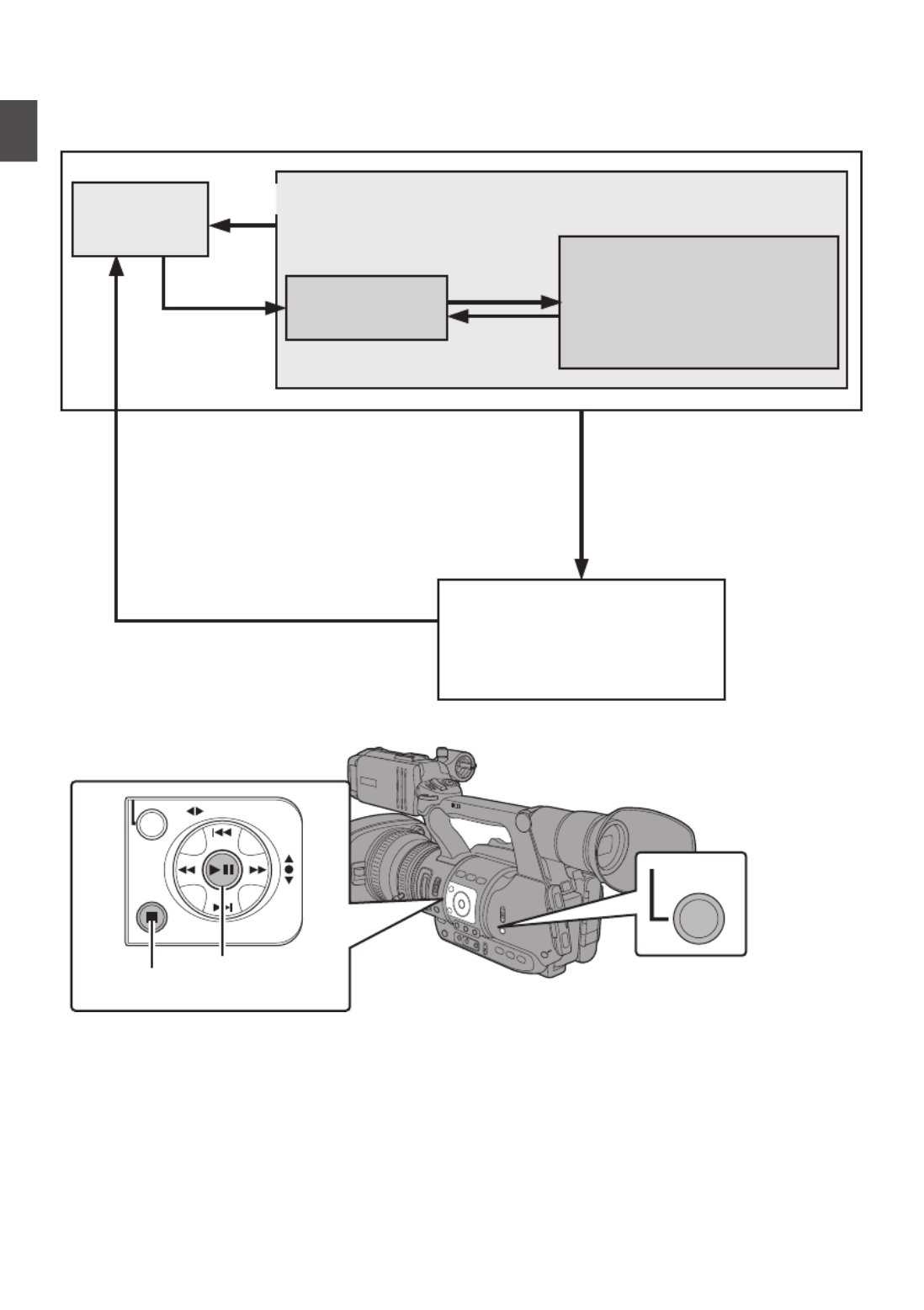
Operation Modes
This camera recorder has three operation modes - Camera mode, Media mode, and USB mode.
.
AE LEVEL
MENU/THUMB
CANCEL
MODE
Media Mode
Thumbnail
Display
(Playback/Pause/
Frame-by-Frame/
Fast Forward/Rewind/
Clip Jump)
Playback
USB Connection (When the
confirmation to change to
USB mode appears and
[Change] is selected)
(USB Mass Storage Class)
USB Mode
Stop Button
Stop
Button
Playback Button
Playback
Button
Connection disabled on PC
Press and hold
[MODE] button
[MODE] Button
Camera
Mode
16
Introduction

Operation Mode Description
Camera Mode 0This is the camera shooting mode. The camera recorder starts up in Camera
mode when the power is turned on.
0Camera images are output on the viewfinder and LCD monitor. When a
recordable SD card is inserted, the camera recorder enters the recording
standby mode. “STBY” appears on the operation mode display area of the
LCD monitor and viewfinder.
0Press the [REC] trigger button to start recording.
Memo :
0Playback of SD card is not possible in Camera mode. However, you can
check the most recently recorded video clip.
( P68 [Viewing Recorded Videos Immediately (Clip Review)] )A
Media Mode 0This mode allows you to play back or delete clips recorded on the SD card.
0When a playable SD card is inserted, the thumbnail or playback screen is
displayed on the viewfinder and LCD monitor.
0Press the [MODE] selection button to enter Media mode when you are not
shooting in Camera mode. Once the camera recorder is in Media mode,
thumbnails of the selected media slot are displayed.
USB Mode 0This mode allows you to connect to a PC and transfer the files on an SD card
to the PC.
0When the camera recorder is connected to a USB cable, the message
“Change to USB Mode?” appears.
Select [Change] and press the Set button to switch to USB mode.
( P124 [Managing/Editing Clips on a PC] )A
0In USB mode, the camera recorder is recognized by the connected PC as a
peripheral drive. (USB mass storage class only)
Disable the connection on the PC and remove the USB cable from the camera
recorder to switch to Camera mode.
( P124 [Managing/Editing Clips on a PC] )A
Memo :
0When a USB cable is connected during recording, the message appears after
recording stops.
0If playback is in progress, the message appears once the files are closed
automatically, such as when playback stops.
0Files on the PC cannot be written to the SD card.
17
Introduction

Names of Parts
.
SERVO MANUAL
ZOOM
REC
H
E
IJ
GDA CB
K
F
FIX VAR OFF
F
OCU S A S
SIS
T/1
O
IS /2 LO L
UX
/3
MENU/THUMB
AE LEVEL
FOCUS
ND FILTER
1/64
1/1 6
1/4
OFF
P
OW
E
R
MAR KER/6
ZEBRA/5
AE LOCK/4
SHUTTER
WHT BAL
CANCEL
P
USH
A U
TO
IR
IS
GAIN
FULL AUTO
PUSH AUTO
PRESET
B
L
M
HA
ON
O
FF
ON
MANU
∞
MODE
OFF
(CHG)
SLO T
A/B
TIME CODE
AUTO
Bottom
ABuilt-in Microphone
( P57 [Audio Recording] )A
BTally Lamp
( P36 [Tally Lamp] )A
( P130 [Tally Lamp] )A
CMicrophone Holder
( P25 [Attaching an External Microphone] )A
DMicrophone Holder Lock Knob
( P25 [Attaching an External Microphone] )A
EShoe
For mounting separately sold lights and
accessories.
F[FIX/VAR/OFF] Zoom Speed Switch
( P44 [Zoom Operation] )A
For switching the zoom speed of the zoom lever
a at the handle.
GAccessory Mounting Screw Hole
HTripod Mounting Hole
( P25 [Attaching the Tripod] )A
I[REC] Record Trigger Button
Starts/stops recording.
Memo :
0This button is interlocked with the [REC] button
R on the grip and the [REC/HOLD] button atZ
the top of the handle.
J[ZOOM SERVO/MANUAL] Zoom Operation
Servo/Manual Switch
Set to “SERVO” when using the zoom lever at
the grip or the zoom lever at the handle .j a
( P44 [Zoom Operation] )A
KMonitor Speaker
( P81 [Audio Output during Playback] )A
LViewfinder
( P34 [Adjusting the LCD Monitor andA
Viewfinder] )
MVisibility Adjustment Lever
( P34 [Adjusting the LCD Monitor andA
Viewfinder] )
NEyecup
Prevents external light from entering the
viewfinder screen and cameraman’s vision.
( P25 [Attaching the Large Eyecup] )A
OBattery
( P26 [Using a Battery Pack] )A
P[ ] Headphone Jack (Φ3.5 mm)x
( P59 [Monitoring Audio Sound DuringA
Recording Using a Headphone] )
Q[AUX] AUX Input Terminal (Φ3.5 mm)
For connecting to receiver such as wireless
microphone.
18
Introduction
.
A
UX
INPUT2 INPUT1
DEVICE
AV
A
BATT.RELEASE
POWER
/C
HG
B
HDMI
REMOTE
DC
HD/SD
SDI
REC
W
T
REC
HOLD
IN OUT
TC
L
M
N
O
d
R S T
X
Zabc
Q
P
U
V
Y
W
R[REC] Record Trigger Button
Starts/stops recording.
Memo :
0This button is interlocked with the [REC] button
I at the bottom of the lens and the [REC/
HOLD] button at the top of the handle.Z
S[C.REVIEW/7] Clip Review/User 7 Button
For checking the most recently captured
images.
( P68 [Viewing Recorded VideosA
Immediately (Clip Review)] )
You can also use it as a user button by assigning
a specific feature in the menu setting to this
button.
( P36 [Assigning Functions to UserA
Buttons] )
TZoom Lever at the Grip
To operate zoom servo with the zoom lever at
the grip, set the [ZOOM SERVO/MANUAL]
switch to “SERVO”.0
( P44 [Using the Zoom Lever at the Grip] )A
U[TC] TC Input/Output Terminal
( P60 [Time Code and User’s Bit] )A
V[IN/OUT] TC IN/OUT Selection Switch
( P64 [Synchronizing Time Code onA
Another Camera] )
WHood Release Button
( P26 [Attaching/Detaching the Hood] )A
XExternal Microphone Cable Clamp
( P25 [Attaching an External Microphone] )A
Y[INPUT1/INPUT2] Audio Input Terminal 1, 2
(XLR 3-pin x 2)
( P25 [Attaching an External Microphone] )A
Z[REC/HOLD] Record Trigger Button/Lock
Switch
Starts/stops recording.
Set the switch to [HOLD] to lock the [REC]
Trigger button.
Memo :
0This button is interlocked with the [REC] button
R I on the grip and the [REC] button at the
bottom of the lens.
0The [REC] button on the grip and the [REC]R
button at the bottom of the lens will not beI
locked.
aZoom lever at the Handle
( P44 [Using the Zoom Lever at theA
Handle] )
bShoulder Belt Mount (x2)
For mounting a shoulder belt (sold separately).
Caution :
0Be sure to use a shoulder belt with the strength
to withstand the weight of this camera recorder.
0If the shoulder belt is not properly attached, the
camera recorder may fall and cause injuries.
0Check the instruction manual provided with the
shoulder belt before using.
c[POWER/CHG] Power/Charging Display Lamp
( P26 [Using a Battery Pack] )A
d[BATT. RELEASE] Battery Lock Release Button
( P27 [Removing the Battery] )A
19
Introduction

Side Control Panel
.
ND FILTER FOCUS
AE LEVEL
MANU
PUSH AUTO
MENU/THUMB
FOCUS ASSIST/1 OIS / 2 LOLUX / 3
1/64
1/16
1/4
OFF
PRESET
IRIS
GAIN
CANCEL
L
M
H
B
A
WHT BAL SHUTTER
FULL AUTO
MODE
POWER
ON
OFF
(CHG)
ON
OFF
AE LOCK/4 ZEBRA/5 MARKER/6
PUSH AUTO
TIME CODE
AUTO
A
B
C
E
S R Q
O
N
MLKJ
T
D
P
H
I
U
F G
A[FOCUS AUTO/MANU/∞] Focus Switch
( P45 [Focus Operation] )A
B[ND FILTER] ND Filter Switch
( P53 [Setting the ND Filter] )A
C[PUSH AUTO] Focus Push Auto Button
( P46 [One Push Auto Focus] )A
D[IRIS] Iris Auto/Manual Selection Button
( P49 [Adjusting the Iris] )A
E[PUSH AUTO] Iris Push Auto Button
( P49 [Adjusting the Iris] )A
F[GAIN] Gain Auto/Manual Selection Button / [L/
M /H] Sensitivity Selection Switch
( P50 [Setting the Gain] )A
G[WHT BAL] White Balance Auto/Manual
Selection Button / [B/A/PRESET] Selection
Switch
( P53 [Adjusting the White Balance] )A
H[SHUTTER] Shutter Speed Auto/Manual
Selection Button
( P51 [Setting the Electronic Shutter] )A
I[ ] One Push Auto White Balance Buttony
J[FULL AUTO ON/OFF] Full Auto Switch
( P48 [Adjusting the BrightnessA
Automatically] )
( P56 [Automatic White Balance ModeA
(FAW: Fulltime Auto White balance)] )
K[AE LOCK/4] AE Lock/User 4 Button
When Gain, Iris, and Shutter are set to “AUTO”,
their respective values and the value of white
balance are locked when the [AE LOCK/4] button
is pressed.
You can also use it as a user button by assigning
a specific feature in the menu setting to this
button.
( P36 [Assigning Functions to UserA
Buttons] )
L
[ZEBRA/5] Zebra/User 5 Button
( P65 [Setting Zebra Pattern] )A
You can also use it as a user button by assigning
a specific feature in the menu setting to this
button.
( P36 [Assigning Functions to UserA
Buttons] )
M[MARKER/6] Marker/User 6 Button
This button toggles ON/OFF the marker, safety
zone, and center mark displays.
You can also use it as a user button by assigning
a specific feature in the menu setting to this
button.
( P36 [Assigning Functions to UserA
Buttons] )
N[MODE] Camera/Media Mode Selection Button
( P16 [Operation Modes] )A
O[POWER ON/OFF(CHG)] Lock Power ON/OFF
Switch
Turns ON/OFF the power.
0Hold down the lock button (blue) in the center
to toggle ON/OFF.
0When the power is turning OFF, “P.OFF”
appears on the LCD monitor and viewfinder.
0Wait for 5 seconds or more to turn on the
power again.
PCross-Shaped Button ( )/Set Button ( )JKHI R
The function changes according to the
operation status of the camera recorder.
o During menu operation (all modes)
( P86 [Basic Operations in Menu Screen] )A
Center Set button ( ) : Confirms menu itemsR
and setting values
Cross-shaped button
( )JK
: Selects menu items
and setting values
o During Camera mode
Shutter operation:
Center Set button ( ) : Shutter ON/OFFR
Cross-shaped button
( )JK
: Switches shutter
speed when shutter
is ON
AE level operation : Cross-shaped button
( )HI
Memo :
0When [Camera Function] menu [AE LEVELB
SW] is set to “AE LEVEL/VFR”, the cross-
shaped button ( ) is used to set the number ofHI
frames during Variable Frame Rec.
( P77 [Variable Frame Rec] )A
( P91 [ AE LEVEL SW ] )A
Q[LOLUX/3] Low-light Shooting/User 3 Button
For switching the low-light shooting mode ON
or OFF.
You can also use it as a user button by assigning
a specific feature in the menu setting to this
button.
( P36 [Assigning Functions to UserA
Buttons] )
20
Introduction
R
[OIS/2] Optical Image Stabilizer/User 2 Button
For switching the image stabilizer feature mode
ON or OFF.
You can also use it as a user button by assigning
a specific feature in the menu setting to this
button.
( P36 [Assigning Functions to UserA
Buttons] )
S[FOCUS ASSIST/1] Focus Assist/User 1 Button
For switching the focus assist function ON or
OFF.
( P46 [Focus Assist Function] )A
You can also use it as a user button by assigning
a specific feature in the menu setting to this
button.
( P36 [Assigning Functions to UserA
Buttons] )
T[MENU/THUMB] Menu/Thumbnail Button
0Displays the menu screen during Camera
mode.
( P86 [Basic Operations in Menu Screen] )A
0Displays the menu screen when the button
is pressed during thumbnail display in the
Media mode.
0Stops playback and displays the thumbnail
screen when the button is pressed during
playback screen display in the Media mode.
U[CANCEL] Cancel Button
Cancels various settings and stops playback.
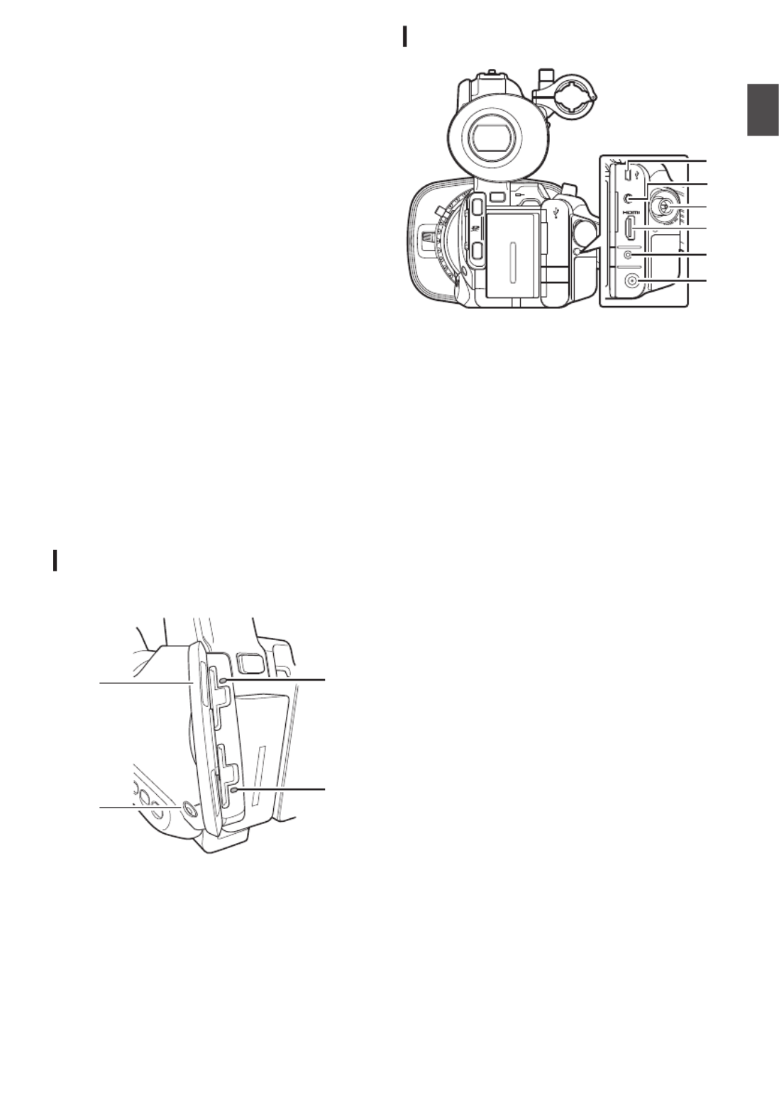
SD Slot
( P37 [SD Card] )A
.
A
B
C
D
ASD Card Cover
B[SLOT A/B] Card Slot Selection Button
For switching the active card slot during
shooting and playback.
CCard Slot B Status Indicator
DCard Slot A Status Indicator
Rear Terminal
.
DEVICE
AV
HDMI
REMOTE
DC
HD/SD
SDI
POWER
/CHG
BATT.RELEASE
A
B
OPEN
CLOSE
AV
DEVICE
DC
REMOTE
C
D
E
F
B
A
A[DEVICE] USB Mini Terminal
( P124 [Managing/Editing Clips on a PC] )A
B[AV] AV Output Terminal
( P126 [Connecting External Monitor] )A
C[HD/SD SDI] SDI Output Terminal (BNC)
( P126 [Connecting External Monitor] )A
D[HDMI] HDMI Output Terminal
( P126 [Connecting External Monitor] )A
E[REMOTE] Remote Terminal
( P127 [Connecting Wired Remote Control] )A
F[DC] DC Input Terminal
Input terminal for DC 12 V power supply.
Connects with the bundled AC adapter.
( P28 [Using AC Power (DC IN Power)] )A
21
Introduction

LCD Monitor
.
MENU/THUMB
CANCEL
CH1
INT
INPUT1
INPUT2
AUTO
MANUAL
CH2
INPUT2
MONITOR
DISPLAY STATUS
INPUT1
PEAKINGLCD BRIGHT
CH2CH1
LINE
MIC
MIC
+48V
CH1
BOTH
CH2
B
C
H I
A
D
FGE
JKLN M
ALCD Monitor
( P34 [Adjusting the LCD Monitor andA
Viewfinder] )
B[MENU/THUMB] Menu/Thumbnail Button
0Displays the menu screen during Camera
mode.
( P86 [Basic Operations in Menu Screen] )A
0Displays the menu screen when the button
is pressed during thumbnail display in the
Media mode.
0Stops playback and displays the thumbnail
screen when the button is pressed during
playback screen display in the Media mode.
CLCD Cross-Shaped Button ( )/Set ButtonJKHI
( )R
The function changes according to the
operation status of the camera recorder.
0During menu operation (all modes)
( P86 [Basic Operations in Menu Screen] )A
Center Set button ( ) : Confirms menuR
items and setting
values
Cross-shaped button
( )JK
: Selects menu
items and setting
values
0During Camera mode
You can also use it as a user button by assigning
a specific feature in the menu setting to this
button.
( P36 [Assigning Functions to UserA
Buttons] )
D[CANCEL] Cancel Button
Cancels various settings and stops playback.
E[CH1/CH2] CH1/CH2 Recording Level
Adjustment Knob
( P57 [Audio Recording] )A
F
[LCD BRIGHT +/-] LCD Display Brightness
Adjustment Button
( P34 [Adjusting the Brightness] )A
G[PEAKING +/-] LCD/VF Contour Adjustment
Button
( P35 [Adjusting the Contour (LCD)] )A
( P35 [Adjusting the Contour (Viewfinder)] )A
H[DISPLAY] Display Button
0Press the [DISPLAY] button to switch to the
display screen during normal screen display
(when the menu screen is not displayed).
( P32 [Display Screen] )A
0Switches between [Main Menu] and
[Favorites Menu] when the [DISPLAY]
button is pressed while the menu screen is
displayed.
( P86 [Basic Operations in Menu Screen] )A
I[STATUS] Status Screen Display Button
Press the [STATUS] button to display the status
screen on the viewfinder and LCD monitor
during normal screen display (when the menu
screen is not displayed).
( P33 [Status Screen] )A
J[MONITOR]/[+/-] Audio Monitor Selection
Switch/Volume Adjustment Button
Switches the audio monitor and adjusts the
monitor speaker/headphone.
( P59 [Monitoring Audio Sound DuringA
Recording Using a Headphone] )
K[INPUT1/INPUT2] Audio Input Signal Selection
Switch
( P57 [Audio Recording] )A
L[CH2] CH2 Audio Input Signal Selection Switch
Select the audio input terminal to record to CH2.
( P57 [Audio Recording] )A
M[CH1] CH1 Audio Input Signal Selection Switch
( P57 [Audio Recording] )A
N[CH1/CH2 AUTO/MANUAL] CH1/CH2 Audio
Recording Mode Switch
( P58 [Adjusting Audio Recording Level] )A
22
Introduction

Lens Section
.
E
C DA B
AFilter Built-In Screw
0Transparent or UV filter for lens protection,
or filters for various effects can be installed.
0Installable filter types: Φ72mmP0.75
Memo :
0Remove the lens hood when installing the filter.
( P26 [Attaching/Detaching the Hood] )A
BLens Cover Open/Close Switch
( P26 [Opening/Closing the Lens Cover] )A
CFocus Ring
( P45 [Focus Operation] )A
DZoom Ring
( P44 [Zoom Operation] )A
To operate zoom with this ring, set the [ZOOM
SERVO/MANUAL] switch to “MANUAL”.
EIris Ring
( P49 [Adjusting the Iris] )A
To operate auto iris, press the [IRIS] button on
the side control panel.
( mark appears on the screen)a
23
Introduction
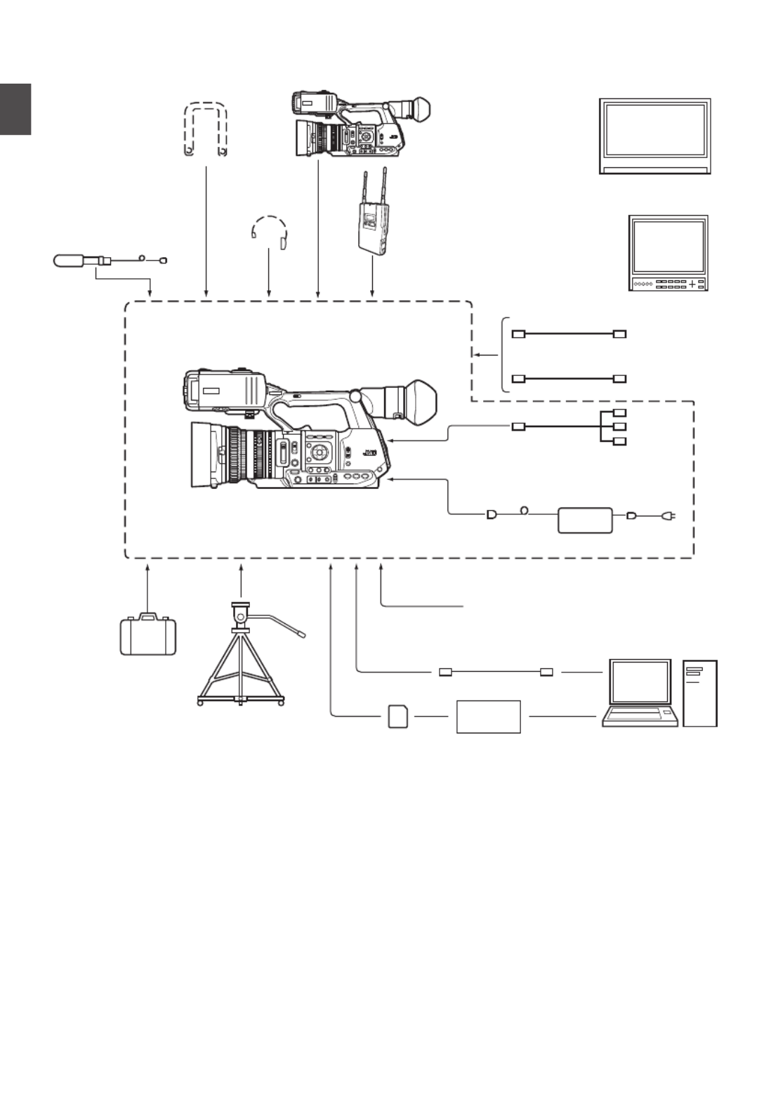
Basic System Diagram
.
Wireless Microphone
Receiver
RCA pin
AV Cable
HDMI Cable
[AUX]
[TC]
Carrying Case
Tripod
SDHC/SDXC
Memory Card
SDHC/SDXC
Card Reader
USB Cable
Battery
AC Adapter
Remote Control Unit
Non-linear Editing
System
GY-HM600
Microphone
Monitor
Monitor
SDI Cable
BNC
Earphone
Shoulder Belt GY-HM600
24
Introduction

Settings and Adjustments
Before Use
.
Adjusting the Grip Belt
Open the pad and adjust the position of the grip belt
accordingly.
.
AU X
INPUT2 INPUT1
DE VIC E
A
V
A
BA
TT .RE LEA S
E
PO W
ER
/C HG
B
HDM I
REM OTE
D
C
HD/SD
SDI
REC
Caution :
0If the grip is loose, the camera recorder may fall
off resulting in injuries or malfunction.
Attaching an External Microphone
You can attach a separately sold microphone to the
microphone holder.
.
4
5
1, 3
2
1Turn the knob on the microphone holder
anticlockwise to loosen and open the
microphone holder.
2Place the microphone in the microphone
holder.
3Turn the knob on the microphone holder
clockwise to secure the microphone.
4Connect the microphone cable to the [INPUT1]
or [INPUT2] terminal.
5Pin the microphone cable to the clamp.
6Perform the settings for the microphone
correctly.
( P57 [Audio Recording] )A
Attaching the Tripod
Use the screw hole at the bottom of this camera
recorder.
(3/8×16UNC, 1/4×20UNC)
Use the screw hole that suits the tripod.
To prevent the camera recorder from falling off,
which may result in injuries or damages, read the
instruction manual of the tripod to be used and
make sure that it is securely attached.
.
o Bottom
Caution :
0Use the tripod on a stable surface.
0To prevent the camera recorder from falling,
attach securely using the rotation prevention
hole.
0Use screws with screw length 5 mm and below.
Attaching the Large Eyecup
0Attach the large eyecup to prevent external light
from entering the viewfinder screen and
cameraman’s vision.
0Align and attach to the groove of the eyecup
mounted on the camera recorder.
0The large eyecup can be attached in any
direction.
.
Large Eyecup (supplied)
Eyecup
Memo :
0Do not remove the eyecup that is premounted
on the camera recorder.
25
Preparations

Opening/Closing the Lens Cover
Use the lens cover open/close switch to open or
close the lens cover.
Before shooting, open the lens cover.
When this camera recorder is not in use, close the
lens cover to protect the lens.
.
Caution :
0Do not press against the lens cover with force.
Doing so may damage the lens or the cover.
Attaching/Detaching the Hood
Attaching the Hood
Align the markings on the camera recorder and
hood; turn the hood in the direction of the arrow until
it is locked.
.
Detaching the Hood
0Remove the hood when attaching a filter,
teleconverter or wide converter to the front of the
lens.
0While pressing the hood release button, turn the
hood in the anti-clockwise direction to remove it.
.
Power Supply
To use this camera recorder, you can attach a
battery pack or connect an AC adapter to it.
( P26 [Using a Battery Pack] )A
( P28 [Using AC Power (DC IN Power)] )A
Caution :
0Set the [POWER ON/OFF(CHG)] switch to
“OFF(CHG)” before changing the power supply
that operates this camera recorder.
Using a Battery Pack
Charging the Battery
Charge the battery immediately after purchase or
when the battery power is running low.
* The battery is not charged when purchased.
.
1
2
3
4
4
POWER
/CHG
MODE
POWER
ON
OFF
(CHG)
26
Preparations

1
Hold down the lock button (blue) at the center of
the [POWER ON/OFF(CHG)] switch to set to
“OFF(CHG)”.
2Attach the supplied battery.
Slide it in until you hear a click.
3Connect the supplied AC adapter to the [DC]
terminal.
4Connect the AC adapter to a power outlet.
0The [POWER/CHG] lamp blinks during
charging and will go out after charging is
complete.
0Remove the AC adapter after charging is
complete.
Memo :
0Blinking of the [POWER/CHG] lamp during
charging indicates the charge level.
[POWER/CHG] Lamp Charge Level
Orange blinking (4 times per
second)
Less than 25%
Orange blinking (3 times per
second)
Less than 50%
Orange blinking (2 times per
second)
Less than 75%
Orange blinking (1 time per
second)
Less than 100%
Light goes out Fully charged
Removing the Battery
.
1
2
MODE
POWER
ON
OFF
(CHG)
1
Hold down the lock button (blue) at the center of
the [POWER ON/OFF(CHG)] switch to set to
“OFF(CHG)”.
2While pressing and holding the [BATT.
RELEASE] button, push up and remove the
battery in the direction of the arrow.
Caution :
0Do not remove the battery when the [POWER
ON/OFF(CHG)] switch is “ON”.
0Do not insert or remove the DC cable when the
battery is in use.
0Leaving the camera recorder unused with the
battery inside will deplete the battery power
even if you set the [POWER ON/OFF(CHG)]
switch to “OFF(CHG)”. Remove the battery if
you are not using the camera recorder.
Estimated Charging and Continuous
Recording Times
o Charging Time (supplied SSL-JVC50 battery
pack)
Approx. 4 h
Memo :
0Use up the charge completely before you
charge the battery. If the battery is not fully
discharged before charging, the battery
capacity may drop after repeated cycles.
0If the battery capacity drops due to repetitive
shallow charging and discharging, it may be
recovered by using up the charge completely
and then fully charging the battery again.
0If you charge the battery immediately after using
while the battery is still warm, it may not be fully
charged.
0It is recommended that you charge the battery
in an environment between 10 °C and 35 °C
(50 °F and 95 °F). The battery may not be fully
charged or the charging time may be prolonged
if charged under low temperatures (below 10 °C/
50 °F).
o Continuous Operating Time (supplied SSL-
JVC50 battery pack)
Approx. 2 hrs 45 mins
Memo :
0Actual operating times may differ depending on
the age of the battery, charging condition, and
operating environment.
0Operating time is shortened in cold
environment.
0The operating time may shorten when power
zoom is used, accessories are connected, or
when the LCD monitor is frequently used.
0For purchase of spare batteries and battery
charger, consult your nearest JVC dealer.
Precautions for Batteries
0Store the battery in a cool and dry place when
not in use. Do not expose the battery to high
temperatures (such as in a car under direct
sunlight). This will cause battery leakage and
shorten the battery life.
0If the operating time shortens drastically even
after charging, the battery may be reaching the
end of its life. Replace the battery with a new
one.
27
Preparations

Using AC Power (DC IN Power)
Use the supplied AC adapter to operate the camera
recorder with AC power.
.
1
MODE
POWER
ON
OFF
(CHG)
2
1Connect the DC cable of the AC adapter to the
[DC] terminal of the camera recorder.
0Check that the power switch of the camera
recorder is set to “OFF(CHG)”.
0Open the cover of the [DC] terminal and
connect as shown in the diagram.
2
Hold down the lock button (blue) at the center of
the [POWER ON/OFF(CHG)] switch to set to
“ON”.
Power will be supplied to the camera recorder.
Caution :
0Do not insert or remove the DC cable during
recording.
0Do not use power supply of high voltage
fluctuation, containing noise such as ripple, or
with insufficient capacity.
Charging the Built-In Battery
0The date/time and time code data are stored
using the built-in rechargeable battery.
0When power is connected to the camera
recorder, the built-in battery always gets
charged. When the power is disconnected, the
battery gradually discharges.
0The battery will be totally discharged if left
unused for 3 months and the date/time and time
code data will be reset. When this happens, set
the [POWER ON/OFF(CHG)] switch to “ON” to
display the [Initial Setting] screen, then set the
date/time.
( P30 [Initial Settings] )A
Power Status Display
Viewfinder Screen and LCD Monitor
The power status is displayed on the display and
menu screens.
Display Description
B 7.4V
B 100min
C 30%
E
Currently powered by a battery.
When the battery power runs out,
the battery mark appears hollow,
and “RES” (yellow) is displayed.
Memo :
0The display can be set using
[Battery] of [Display Settings]
in the [LCD/VF] menu.
( P100 [ Battery ] )A
GCurrently powered by an AC
adapter.
Memo :
0If the supplied battery (or equivalent battery sold
separately) is not used, the battery mark which
indicates the battery level may not appear.
Display Screen
( P112 [Display Screen in Camera Mode] )A
( P116 [Display Screen in Media Mode] )A
.
100min
50min
282min
P13000K 1/ 100
F1.6
0dB
AE+6
ND 1 /64
5 . 6 f t
12 :34 :56
Jan 24, 2012
00: 00:00.00
1920x1080
60 i HQ
4030 20 10 0
Menu Screen
( P87 [Display and Description of the MenuA
Screen] )
.
28
Preparations

Warnings by Lamp and Warning Tone
Warning status is indicated by tally lamp and
warning tone.
0The tally lamp blinks.
0The warning tone is output from the monitor
speaker or [ ] terminal.x
Memo :
0If you continue to use the camera recorder while
the power warning is displayed, the camera
recorder will stop automatically when the battery
or supplied voltage from the AC adapter
becomes lower.
Caution :
0The remaining battery power and time are
displayed as they are from the battery
information. Accurate data may not be displayed
depending on the battery condition. Replace the
battery as soon as possible when the remaining
battery power and time are low.
Turning On/Off the Power
Turning On the Power
1
Hold down the lock button (blue) at the center of
the [POWER ON/OFF(CHG)] switch to set to
“ON”.
The camera recorder starts up in Camera mode
and is ready for shooting.
Memo :
0The camera recorder always start up in Camera
mode when the [POWER ON/OFF(CHG)]
switch is set to “ON”. Use the [MODE] button at
the side of the camera recorder to switch mode.
( P16 [Operation Modes] )A
.
MODE
POWER
ON
OFF
(CHG)
Turning Off the Power
Sets the camera recorder to the recording standby
or stop mode.
1
Hold down the lock button (blue) at the center of
the [POWER ON/OFF(CHG)] switch to set to
“OFF(CHG)”.
2Remove the battery and the power to the [DC]
terminal (when not in use for a long time).
Auto Power Off function
When [Auto Power Off] in the [System] menu is set
to “On”, the power turns off automatically when the
camera recorder is not operated for 5 minutes or
longer while running on battery.
( P104 [ Auto Power Off ] )A
Memo :
0When both the battery and AC adapter are
connected, power from the AC adapter
connection will be used. As such, the [Auto
Power Off] function will not have any effect.
Caution :
0Do not set the [POWER ON/OFF(CHG)] switch
to “OFF(CHG)” during recording. Check that the
operation mode display is “STBY” or “STOP”
before you turn off the power.
0If you have mistakenly set the [POWER ON/
OFF(CHG)] switch to “OFF(CHG)” during
recording, wait for 5 seconds or more before you
turn on the power again.
0When turning off the power, first set the
[POWER ON/OFF(CHG)] switch of the camera
recorder to “OFF(CHG)”. Do not remove the
battery or turn off the AC power while the
[POWER ON/OFF(CHG)] switch is set to “ON”.
29
Preparations

Initial Settings
When the power is first turned on, the Initial Setting
screen for performing the initial settings in the
camera recorder appears.
Set the date/time of the built-in clock in the [Initial
Setting] screen.
All operations are disabled until initial settings are
complete.
.
MODE
POWER
ON
OFF
(CHG)
AE LEVEL
MENU/THUMB
CANCEL
MENU/THUMB
CAN CEL
Memo :
0It is recommended to use the AC adapter as the
power supply.
0Be sure to close the lens cover.
1
Hold down the lock button (blue) at the center of
the [POWER ON/OFF(CHG)] switch to set to
“ON”.
The Initial Setting screen appears.
.
2Ensure that the lens cover is closed, and press
the Set button ( ).R
0Self-diagnosis starts.
0A progress bar appears, and “Complete
Diagnosis” appears when the diagnosis is
complete.
.
Memo :
0It takes about 6 minutes to complete the
diagnosis. During the diagnosis, do not operate
or turn off the camera recorder.
3Press the Set button ( ) after confirming the exitR
screen.
The [Initial Setting] screen appears.
0For GY-HM600U
.
0For GY-HM600E
.
30
Preparations

Memo :
0The [Initial Setting] screen appears when the
power is turned on for the first time and when the
power is turned on after the built-in battery is fully
discharged.
0The configured date/time data is saved in the
built-in rechargeable battery even if the power is
turned off.
4Set the time zone and date/time.
AMove the cursor with the cross-shaped button
( ) and select the setting item.HI
BChange the values with the cross-shaped
button ( ).JK
5Press the Set button ( ) after setting isR
complete.
The clock is set to 0 seconds of the input date/
time.
Memo :
0The configured date/time data can be displayed
on the LCD monitor and viewfinder and be
recorded to the SD card.
0The value of the year can be set in the range of
“2000” to “2099”.
Changing the Time after Initial Setting
Setting the Date/Time
( P105 [ Date/Time ] )A
1Select [System] menu [Date/Time].B
The [Date/Time] screen appears.
2Set the date and time.
AMove the cursor with the cross-shaped button
( ) and select the setting item.HI
BChange the values with the cross-shaped
button ( ).JK
3Press the Set button ( ) after setting isR
complete.
The clock is set to 0 seconds of the input date/
time.
Changing the Display Style
You can change the display style of the date/time
on the menu.
Setting the Date Display (Date Style)
( P100 [ Date Style ] )A
The date display can be changed in the [LCD/VF]
menu [Display Settings] menu [Date Style]B B
item.
Setting the Time Display (Time Style)
( P100 [ Time Style ] )A
The time display can be changed in the [LCD/VF]
menu [Display Settings] menu [Time Style]B B
item.
Date/Time Display in Each Operation
Mode
During Camera mode:
Date/time of the built-in clock is displayed.
During Media mode:
Shooting date/time of the clip being played back is
displayed.
31
Preparations

Displays on the LCD
Monitor and Viewfinder
You can display the camera status, media
information, zebra pattern, and various markers in
the video image on the LCD monitor and viewfinder
screen during shooting.
Memo :
0When [Main Menu] [A/V Set] menu [Video B B
Set] B [Display On TV] is set to “On”, the display
screen and menu screen are also displayed in
the video image of the video signal output
terminal.
( P101 [ Display On TV ] )A
Display Screen
Display Screen in Camera Mode
0The display switches between three screen
types with every press of the [DISPLAY] button.
(Display 0 1 2 0)BBB
0Press the [STATUS] button to switch to the
status screen.
.
Display 2 screen
Display 1 screen
Display 0 screen
100min
50min
282min
P13000K 1/ 100
F1.6
0dB
AE+6
ND 1 /64
12 :34 :56
Jan 24, 2012
00: 00:00.00
1920x1080
60 i HQ
4030 20 10 0
5 . 6 f t
P13000K 1/ 100
F1.6
0dB
AE+6
ND 1 /64
12 :34 :56
Jan 24, 2012
00: 00:00.00
4030 20 10 0
5 . 6 f t
Display Screen (VF/LCD) in Media Mode
( P116 [Display Screen in Media Mode] )A
0This is the screen display during clip playback in
Media Mode.
0The display switches between three screen
types with every press of the [DISPLAY] button.
(Display 0 1 2 0)BBB
.
1000/2000
12 :34 :56
Jan 24, 2012
00: 00:00.00
1920x1080
60 i HQ
4030 20 10 0
1000/2000
282min
12 :34 :56
Jan 24, 2012
00: 00:00.00
1920x1080
60 i HQ
4030 20 10 0
1000/2000
x5
SELECT
x5
INFO
Display 2 screen
Display 1 screen
Display 0 screen
32
Preparations

Status Screen
0This screen allows you to check the current
settings.
0To display the status screen, press the
[STATUS] button in the normal screen.
0The status display differs according to the
operation mode (two types).
( P16 [Operation Modes] )A
0Press the [STATUS] button to switch to the
display screen.
0Press the [MENU] button at each status screen
(other than the [Camera Information] screen) to
enter the setting screen.
0Use the cross-shaped button ( ) to switchHI
screens as follows:
.
USB Mode Screen
This screen displays the USB mode.
.
Warning Display
0Warning display is displayed in the display
screen (Camera mode, Media mode).
0If error occurs during status screen display, the
display will return to the display screen to display
the warning.
( P128 [Error Messages and Actions] )A
.
P13000K 1/ 100
F1. 6
0dB
AE+6
ND 1 /64
5 . 6 f t
12 :34 :56
Jan 24 ,2012
00 : 00 : 00.00
4030 20 10 0
Warning Display Area
33
Preparations

Adjusting the LCD Monitor
and Viewfinder
You can monitor video images on this camera
recorder using the viewfinder, LCD monitor, or
both.
.
DISPLAY
Normal LCD
Inverted
LCD
Displays on the LCD Monitor and
Viewfinder Screen (VF)
When [LCD + VF] in the [LCD/VF] Menu is Set
to “Off”
( P97 [ LCD + VF ] )A
LCD Monitor Status LCD Display VF Display
LCD closed Normal LCD OFF ON
Inverted LCD ON OFF *
LCD opened Normal LCD ON OFF *
Inverted LCD ON OFF *
* Turns ON when [LCD + VF] in the [LCD/VF] menu
is set to “On”.
Memo :
0
Press and hold the [DISPLAY] button for 2 seconds
to turn ON/OFF the LCD monitor.
0
The function to switch between LCD monitor and
viewfinder displays by pressing the [DISPLAY]
button can be canceled by opening/closing or
rotating the LCD monitor.
0
The viewfinder screen is always displayed when
[LCD + VF] in the [LCD/VF] menu is set to “On”.
0
You can display both the LCD monitor and
viewfinder screen at the same time by setting [LCD
+ VF] in the [LCD/VF] menu to “On”.
( P97 [ LCD + VF ] )A
Adjusting the LCD Monitor
.
2
1
PEAKINGLCD BRIGHT
3
Tilt 90 degrees
downward
Tilt 180 degrees
upward
1Open the LCD cover.
2Incline the LCD cover to a position that enables
easy viewing.
Rotate the LCD monitor to adjust the angle.
0While the LCD monitor is open, you can
rotate it 180 degrees upward or 90 degrees
downward.
0Rotating the LCD monitor 180 degrees
upward enables you to see the screen from
the lens side. To display the image when it is
viewed from the opposite direction (mirror
image), perform setting as follows.
Set [Main Menu] [LCD/VF] menu [LCD B B
Mirror] to “Mirror” B press the Set button ( )R
( P98 [ LCD Mirror ] )A
3Adjust the brightness, contour, and contrast of
the LCD monitor.
You can change the angle and brightness of the
LCD monitor according to your usage condition.
Changing the brightness of the screen will not
affect the recorded images.
Adjusting the Brightness
Use the [LCD BRIGHT +/ ] button to adjust the-
brightness of the LCD monitor.
0The [+] button brightens the monitor and the
[ ] button darkens it.-
0Press the [+] and [ ] buttons simultaneously-
to return to standard settings.
0During adjustment, the brightness level is
displayed on the LCD monitor.
.
P13000K 1 / 10000
F1.8
18dB
AE+6
ND 1/ 64
4030 20 10 0
LCD BRIGHT -10
34
Preparations
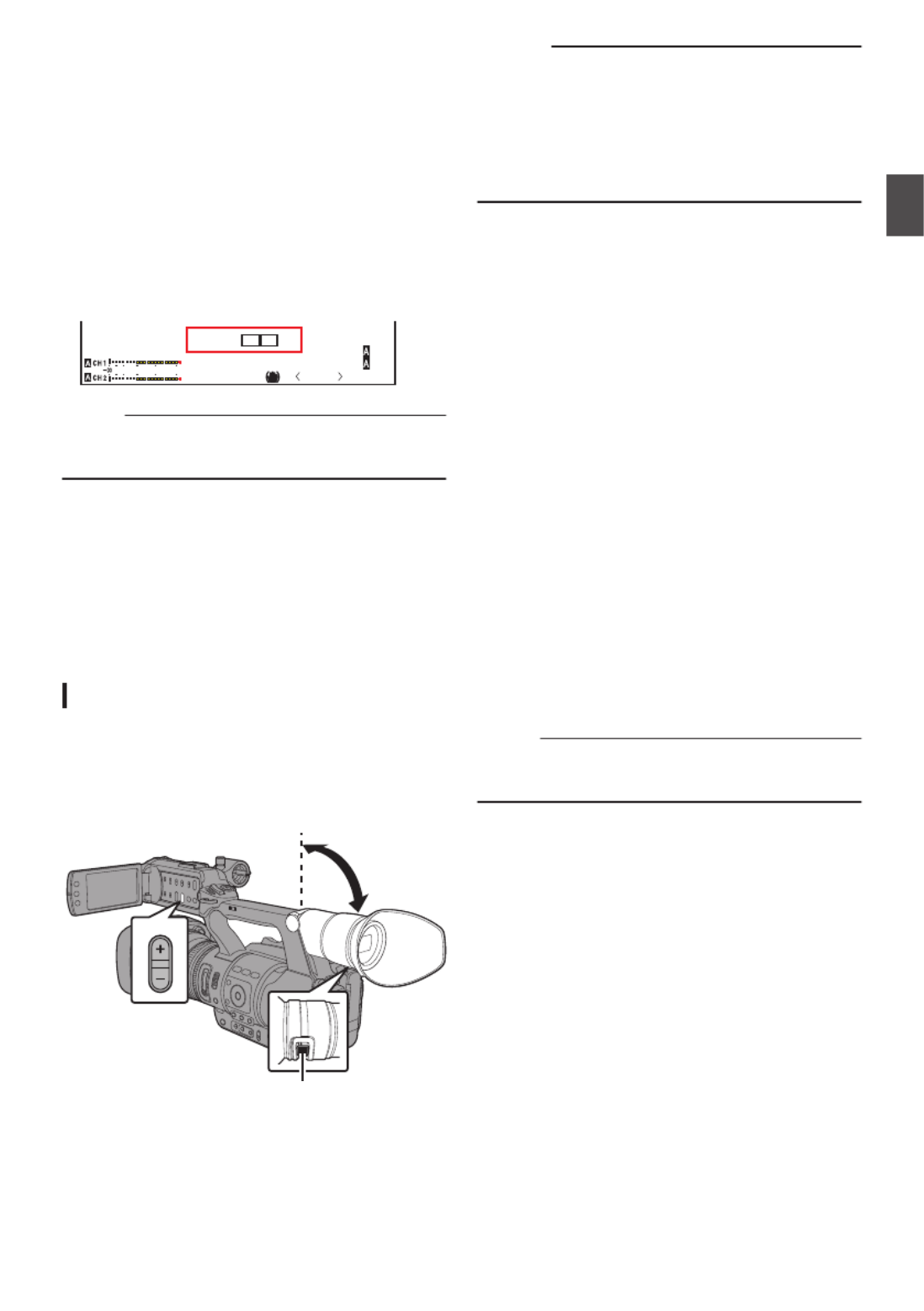
Adjusting the Contour
Use the [PEAKING +/ ] button to adjust the-
contour of the LCD monitor.
(The contour of the viewfinder screen will also
be adjusted at the same time.)
0The [+] button increases contour correction
and the [ ] button decreases contour-
correction.
0Press the [+] and [-] buttons simultaneously
to return to standard settings.
0During adjustment, the contour level is
displayed on the LCD monitor.
.
P13000K 1/ 100
F1.6
0dB
AE+6
ND 1 /64
4030 20 10 0
PEAKING 0
Memo :
0The [PEAKING +/-] operation is disabled in the
Media mode, and its value is fixed at “-10”.
Adjusting the Contrast
Use the [LCD Contrast] menu to adjust the
contrast of the LCD monitor.
0
Select [Main Menu] menu
B
[LCD/VF] menu
B
[LCD Contrast] to adjust.
0
Increasing the value increases the contrast.
[Setting Values: +10 to -10] (Default value: 0)
Adjusting the Viewfinder
You can change the brightness and peaking of the
viewfinder screen according to your usage
conditions.
Changing the brightness of the screen will not
affect the recorded images.
.
PEAKING
1
2
Caution :
0A high-definition viewfinder is used on this
camera recorder in order to provide an accurate
focusing environment. Due to the characteristic
of the display device, colors may appear on the
images when you blink your eyes. This is not a
malfunction. It does not affect the recorded
images, SDI output, AV output, or HDMI output.
1Incline the viewfinder vertically to a position that
enables easy viewing.
2Turn the visibility adjustment lever to adjust the
visibility.
Turn the visibility adjustment lever to sharpen
the image on the viewfinder screen.
3Adjust the brightness, contour, and contrast of
the viewfinder screen.
Adjusting the Brightness
Use the [VF Bright] menu to adjust the
brightness of the viewfinder screen.
0Adjust using [Main Menu] B [LCD/VF] B[VF
Bright].
0Increasing the value increases the
brightness. [Setting Values: +10 to -10]
(Default value: 0)
Adjusting the Contour
Use the [PEAKING +/-] button to adjust the
contour of the viewfinder screen.
The contour of the LCD monitor will also be
adjusted at the same time.
( P35 [Adjusting the Contour] )A
Memo :
0The [PEAKING +/-] operation is disabled in the
Media mode, and its value is fixed at “-10”.
Adjusting the Contrast
Use the [VF Contrast] menu to adjust the
contrast of the viewfinder screen.
0Adjust using [Main Menu] B [LCD/VF] B[VF
Contrast].
0Increasing the value increases the contrast.
[Setting Values: +10 to -10] (Default value:
0)
Displaying in Black and White
You can display the viewfinder screen in black
and white.
0[Main Menu] [LCD/VF] [VF Color] item B B
B B B Press Set button ( ) R Select “Off”
Press Set button ( ).R
( P97 [ VF Color ] )A
35
Preparations
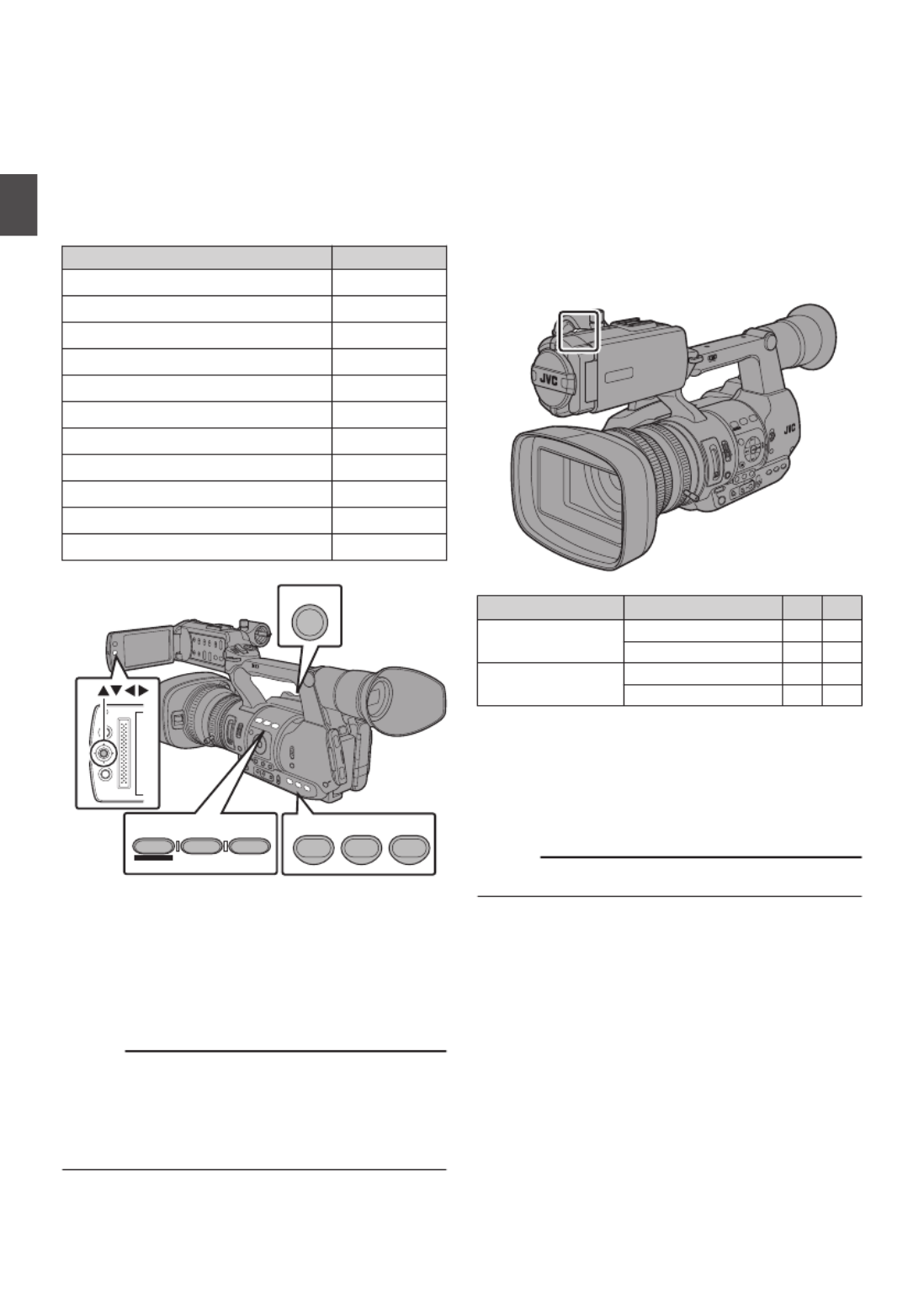
Assigning Functions to
User Buttons
You can assign functions to the following buttons
and use them as user buttons.
By assigning functions to the buttons, the usability
of the camera recorder is enhanced.
Perform settings in the menu items corresponding
to each button.
Button Menu Item
[FOCUS ASSIST/1] Button [USER1]
[OIS/2] Button [USER2]
[LOLUX/3] Button [USER3]
[AE LOCK/4] Button [USER4]
[ZEBRA/5] Button [USER5]
[MARKER/6] Button [USER6]
[C.REVIEW/7] Button [USER7]
LCD Cross-Shaped Button ( ) [LCD KEY▲]J
LCD Cross-Shaped Button ( ) [LCD KEY▼]K
LCD Cross-Shaped Button ( ) [LCD KEY◀]H
LCD Cross-Shaped Button ( ) [LCD KEY▶]I
.
MENU/THUMB
CAN CEL
AE LOCK/4 ZEBRA/5 MARKER/6
FOCUS ASSIST/1 OIS / 2 LOLUX / 3
TIME CODE
C.REVIEW/7
1Assign functions to the buttons from the menu.
Set items in [Main Menu] [Camera B
Function] [User Switch Set] [USER1]- B B
[USER7], [LCD KEY▲], [LCD KEY▶], [LCD
KEY▼], [LCD KEY◀].
( P91 [User Switch Set Item] )A
Memo :
0Operations of the user buttons are interlocked
with the menu settings.
0When the menu screen is displayed, these
buttons function as the menu operation buttons.
( P86 [Basic Operations in Menu Screen] )A
Tally Lamp
This is the indicator lamp for recording and
warning.
The operation changes according to the menu
settings.
The lamp blinks when the battery or remaining
space on the SD card is low. (Camera mode only)
* Set using [Tally Lamp] in the [Main Menu] B
[System] menu.
( P104 [ Tally Lamp ] )A
.
TI ME CO
DE
Menu setting [Tally Lamp] Off On
Functional
information
Warning - J
Caution - o
Recording status Recording - R
Special recording * - R
R: Lights up
J: Blinks four times in 1 second
o: Blinks once in 1 second
* Paused state during special recording ([Clip
Continuous]).
( P73 [Clip Continuous Rec] )A
Memo :
0Blinking takes priority over lighting up.
36
Preparations

SD Card
This camera recorder saves the recorded images
and audio sound on the SD card (sold separately)
in the card slot.
Usable Cards
Use a Class 6/10 SD card.
Memo :
0Depending on the recording format, SD card
with Class 4 or higher performance can also be
used.
( P43 [Selecting System Definition, FileA
Format and Video Format] )
Caution :
0Using cards other than those from Panasonic,
TOSHIBA or SanDisk may result in recording
failure or data loss.
Estimated Recordable Time of SD Cards
The estimated recordable time is only a guide.
Differences may occur depending on the SD card
in use and the battery condition.
( P105 [ Resolution ] )A
( P106 [ Frame & Bit Rate ] )A
QuickTime/MP4 AVCHD
QuickTime
MPEG2/HD
H.264/SD
SP HQ SP HQ SD
720p 1080i 720p/
1080i/
1080p
1080i 1080i 480i/576i
4GB 22 17 12 25 19 47
8GB 45 35 25 50 39 95
16 GB 90 70 50 100 78 190
32 GB 180 140 100 200 156 380
64 GB
(SDXC)
360 280 200 400 312 760
128 GB
(SDXC)
720 560 400 800 624 1520
(Unit: minute)
Memo :
0If the SD card contains files recorded by devices
other than this camera recorder or files that are
saved from a PC, the recordable time may be
shorter or data may not be properly recorded.
0Up to 600 clips per [Format] can be recorded to
one SD card on this camera recorder. When 600
clips are recorded to one card, the remaining
space is displayed as 0 min regardless of the
estimated recordable time, and no further
recording can be performed.
0When [Format] in the [Main Menu] B
[System] [Record Set] [Record Format] B B
menu is set to “AVCHD”, up to 4000 clips can be
recorded to one SD card.
Write-Protect Switch on the SD Card
ASlide the write-protect switch upward to enable
writing or deleting.
BSlide the write-protect switch downward to
prevent writing or deleting. (Images in the card
are protected.)
.
A B
Write/Delete Enabled Write/Delete Disabled
Write-Protect Switch
37
Preparations
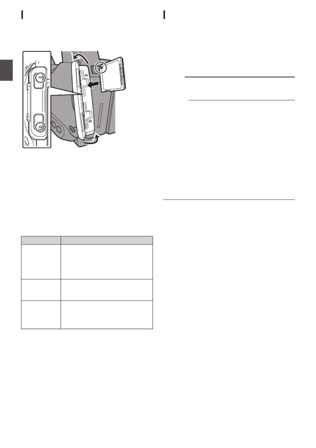
Inserting an SD Card
This camera recorder comes with two card slots
(Slot A and B) for video/audio recording and
playback.
.
1
1
1
11
2
3
1
A
B
2
1Open the SD card cover.
2Insert an SD card with the notched corner
pointing up.
The status indicator of the card slot to which the
card was inserted lights up in red.
3Close the SD card cover.
Card Slot Status Indicator
The following table shows the respective states of
slot A and B.
Lamp Slot Status
Lights up in
red
The inserted SD card is being
accessed. (writing/reading data)
Do not turn off the power of the
camera recorder or remove the SD
card.
Lights up in
green
On standby. The inserted SD card
can be used for recording or
playback.
Light goes out 0SD card is not inserted.
0An unusable card is inserted.
0An SD card is inserted but a
different slot is selected.
Removing the SD Card
1Check that the SD card to be removed is not
being accessed (status indicator of the card slot
lights up in red).
2Open the SD card cover.
3Push the SD card and remove it from the slot.
4Close the SD card cover.
Memo :
0When both slots are inserted with usable SD
cards, the previously selected slot is used.
Caution :
0Data may be lost if you turn off the power of the
camera recorder or remove the SD card when it
is being accessed. All data recorded on the
card, including the file that is being accessed,
may be corrupted. Be sure to check whether the
status indicator is lighted in green or not before
you turn off the power or remove the SD card.
0If you mistakenly remove the card when it is
being accessed, reinsert the card only after the
status indicator goes off.
0The SD card may not be recognized if you insert
and remove the card within a short time. When
this happens, remove the card and wait for a few
seconds before you reinsert.
38
Preparations
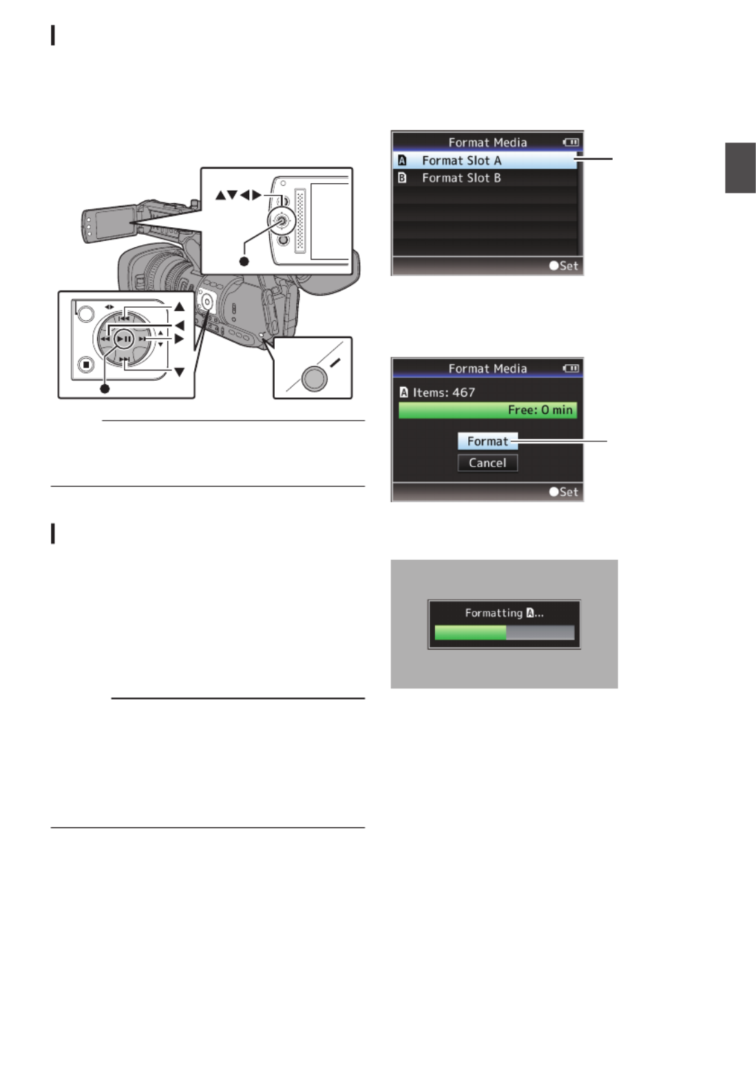
Switching the SD cards
When both card slots are inserted with SD cards,
you can use the [SLOT A/B] button to switch the
card to use.
When the memory on an SD card is full during
recording, data recording automatically switches to
the other card.
.
AE LEVEL
MENU/THUMB
CANCEL
MENU/THUMB
CANCEL
SLOT
A/B
Memo :
0The [SLOT A/B] button is disabled during
recording or playback. Cards will not be
switched even if you press the button.
Formatting (Initializing) SD Cards
When the following cards are inserted, [!FORMAT]
appears at the remaining media display area.
Format the card using the camera recorder menu.
0Unformatted SD cards
0SD cards formatted under different
specifications
* For details of the menu operation, refer to “[Basic
Operations in Menu Screen] P 86”.
Caution :
0Be sure to format the SD card on this camera
recorder. SD cards formatted on a PC and other
peripheral equipment cannot be used on this
camera recorder.
0[!RESTORE] appears at the remaining media
display area when an SD card that requires
restoring is inserted.
1Select [System] [Media] [Format Media]. B B
( P104 [ Format Media ] )A
2Select the slot of the SD card to be formatted
and press the Set button ( ).R
.
2
3The status of the selected SD card appears.
4Select [Format] and press the Set button ( ).R
.
4
5Formatting starts.
.
39
Preparations

6Formatting is complete.
When formatting is complete, “Complete” appears
and the camera recorder returns to the [Format
Media] screen.
Memo :
0During formatting, menu operation is
unavailable but you can start recording.
However, this is only available when a
recordable SD card is inserted in the other slot.
0Formatting cannot be performed in the following
cases.
0Recording is in progress on the SD card to be
formatted.
0SD card is not inserted.
0Write-protect switch of the SD card is set (z
is displayed).
Caution :
0If you format the SD card, all data recorded on
the card, including video data and setup files,
will be deleted.
Restoring the SD Card
It is necessary to restore the SD card if an
abnormality occurs to the data in the card due to
some reasons.
Memo :
0[!RESTORE] appears at the remaining media
display area when an SD card that requires
restoring is inserted.
1Select [System] [Media] [Restore Media]. B B
( P104 [ Restore Media ] )A
2Select the SD card to be restored and press the
Set button ( ).R
.
2
3Restoring starts.
.
4Restoring is complete.
0When restoring is complete, “Complete”
appears and the camera recorder returns to the
[Restore Media] screen.
0When no media that requires restoring is
inserted, the camera recorder returns to the
[Media] menu screen.
Caution :
0[Restore Media] can only be selected in Camera
mode. However, it cannot be selected while the
camera recorder is recording. Select [Restore
Media] in Camera mode when the camera
recorder is not recording.
0[Restore Media] does not restore the SD card to
its original states completely. If restoring fails,
replace or format the SD card. Take note that
formatting erases all the information inside the
SD card.
0Restoring cannot be performed in the following
cases.
0Camera recorder is recording in progress.
0SD card is not inserted.
0Write-protect switch of the SD card is set (z
is displayed).
0Restoring is not required.
40
Preparations

Clips Recorded to SD Cards
Folders in the SD Card
Images captured are recorded to the [PRIVATE]
folder inside the SD card.
Images recorded are sorted into the respective
folders according to the menu settings below.
System Setting Format Setting Record Folder
HD MOV JVC/CQAV
HD MP4 JVC/BPAV
HD AVCHD AVCHD
SD MOV JVC/CQAVC
Memo :
0By formatting (initializing) the SD card from the
[Format Media] menu on the camera recorder,
folders required for recording in the current
[System] settings and [QuickTime(MPEG2)]
settings will be generated.
0When the [System] settings and
[QuickTime(MPEG2)] settings are changed,
folders required for recording in those settings
will be automatically generated.
Caution :
0When a clip inside the folder is moved or deleted
using the Explorer (Windows) or Finder (Mac),
recording to the SD card may fail if formatting
(initializing) of the card is not performed.
Clip (Recorded Data) and Clip Name
0When recording is stopped, the images, audio
and accompanying data which are recorded
from start to stop are recorded as one “clip” on
the SD card.
0An 8-character clip name is automatically
generated for the recorded clip. (“Clip Name
Prefix” + “Clip Number”)
0When [Format] in the [Main Menu] B
[System] [Record Set] [Record Format] B B
menu is set to “AVCHD”, the clip name
generated consists only the Clip Number (5-digit
number).
( P105 [ Format ] )A
Example: In the case of QuickTime/MP4
.
AB CG0 001
This is set to “xxxG” (“xxx” denotes the last 3
digits of the serial number) by default.
Clip Name Prefix (any four alphanumeric characters)
The Clip Number can be reset in
the menu.*
A number in automatic
ascending order is assigned in
the recording order.
Clip Number
* [Clip Set] [Reset Clip Number]B
( P107 [ Reset Clip Number ] )A
Memo :
0Before recording starts, you can set any
characters for the clip name prefix by using
[Main Menu] [System] [Record Set] menuB B
B B[Clip Set] [Clip Name Prefix].
( P107 [ Clip Name Prefix ] )A
0Changes cannot be made after recording.
Recorded Clips
0The recorded materials may be split into several
files but they can be played back continuously
on the camera recorder.
0Clips may be recorded across the two SD cards
in card slots A and B depending on the recording
time of the clip.
0When copying videos in MP4 file format to a
HDD using a PC, it is recommended to use [JVC
ProHD Clip Manager Software], which is found
in the bundled CD-ROM, to maintain continuity.
Caution :
0A clip recorded across several cards cannot be
played back continuously. Continuous playback
is only possible when the recording is made on
one card.
41
Preparations

Basic Shooting
Procedures
Preparations
.
31
MODE
POWER
ON
OFF
(CHG)
4
24
1Supply battery or AC adapter power to the
camera recorder.
( P26 [Power Supply] )A
2Insert an SD card.
( P37 [SD Card] )A
3Turn on the power of the camera recorder.
Hold down the lock button (blue) at the center of
the [POWER ON/OFF(CHG)] switch to set to
“ON”. The camera recorder starts up in Camera
mode and is ready for recording.
4Adjust the angle of the LCD monitor and
viewfinder.
( P34 [Adjusting the LCD Monitor andA
Viewfinder] )
Shooting
1Configure the video and audio input settings.
You have to configure video settings such as
brightness adjustment (iris, gain, shutter) and
white balance adjustment in order to start
shooting. You also have to adjust the audio
input settings and audio recording level for
audio recording.
0Adjusting the Brightness
( P48 [Adjusting the Brightness] )A
0Adjusting the White Balance
( P53 [Adjusting the White Balance] )A
0Adjusting Audio Input Settings and
Recording Level
( P57 [Audio Recording] )A
2Press the [REC] button to start recording to the
SD card.
This camera recorder has three [REC] buttons.
Any of the [REC] buttons can be used to start/
stop recording by default.
The tally lamp lights up in red during recording.
0Zoom Operation
( P44 [Zoom Operation] )A
0Adjusting the Focus Manually
( P45 [Focus Operation] )A
Memo :
0If both the slots are loaded with recordable cards
in the factory default, pressing the [REC] button
starts recording only to the media in the selected
slot. When [Slot Mode] in the [Main Menu] B
[System] [Record Set] menu is set to “Dual”, B
recording can be performed simultaneously to
the cards in both the slots.
( P69 [Dual Rec] )A
0The tally lamp can be turned off with [Tally
Lamp] in the [System] menu.
( P104 [ Tally Lamp ] )A
3Check the most recently captured images.
0Press the [C.REVIEW/7] button on the lens
to activate the Clip Review function. The
most recently captured images are played
back on the LCD monitor and viewfinder
screen.
0After playback, the camera recorder returns
to standby mode (STBY).
( P68 [Viewing Recorded VideosA
Immediately (Clip Review)] )
Memo :
0[Clip Review] is assigned to [C.REVIEW/7]
button in factory default.
0[Clip Review] can also be assigned to other user
buttons.
( P36 [Assigning Functions to User Buttons] )A
42
Shooting

Selecting System
Definition, File Format and
Video Format
You can select the system definition (HD or SD),
file format for recording/playback and the record
format for video images on this camera recorder.
Memo :
0Make a selection in [Main Menu] [Record B
Format] menu.
Selecting a System Definition
Select the system definition in [System].
There are two different definitions for selection.
0HD:
Records in HD (High Definition) quality.
0SD:
Records in SD (Standard Definition) quality.
Selecting a File Format
Select a file format in [Format].
There are three file formats for selection.
0QuickTime(MPEG2):
QuickTime file format (.MOV)
0MP4(MPEG2):
MP4 file format
0AVCHD:
AVCHD file format
Memo :
0The available options vary as follows depending
on the [System] setting.
0For “HD”:
QuickTime(MPEG2), MP4(MPEG2),
AVCHD
0For “SD”:
QuickTime(H.264)
Selecting a Video Format
0Select a [Record Format] from the list of formats.
The selectable [Frame & Bit Rate] changes
according to the settings of [System], [Format],
and [Resolution].
0The recording bit rate (video) is 35 Mbps VBR in
“HQ” mode, and 18.3 Mbps (1080i is 25 Mbps)
CBR in “SP” mode.
0If [Format] is set to “AVCHD”, the recording bit
rate (system rate) is 24 Mbps VBR in “HQ”
mode, and 17 Mbps VBR in “SP” mode.
List of Formats
The following is a list of file formats and video
formats that can be selected on this camera
recorder.
0When [System] is set to “HD”
Record Format
Remarks
Format Resolution Frame &
Bit Rate
QuickTime
/MP4
1920x1080 60i(HQ)
30p(HQ)
50i(HQ)
25p(HQ)
24p(HQ)
1440x1080 60i(HQ)
50i(HQ)
60i(SP)
HDV
compatible
50i(SP)
HDV
compatible
1280x720 60p(HQ)
30p(HQ)
50p(HQ)
25p(HQ)
24p(HQ)
60p(SP)
HDV
compatible
50p(SP)
HDV
compatible
AVCHD 1920x1080 60i(HQ)
Recordable
using Class 4
50i(HQ)
60i(SP)
50i(SP)
0When [System] is set to “SD”
When [System] is set to “SD”, the video format is
fixed as follows for the different models.
Record Format
Remarks
Format Resolution Frame &
Bit Rate
QuickTime
720 x 480 60i (U
model)
Recordable
using Class 4
720 x 576 50i (E
model)
43
Shooting

Selecting the Aspect Ratio of SD Videos
Select an aspect ratio for the images.
The available options vary as follows depending on
the [System] setting.
0For “HD”: Fixed at 16:9
0For “SD”: Can select 16:9 or 4:3
Setting the Record Format Menu
1Display the [Main Menu] [Record Format] B
menu.
2Set each of the items.
3After setting is complete for all items, press the
[FOCUS ASSIST/1] button.
0The record format is switched.
0A “Please Wait...” message appears on the
screen during switching.
Zoom Operation
Adjusts the angle of view.
Zoom ratio: 1x to 23x (optical zoom only)
Zooming can be operated using any of the three
levers/rings below.
0Zoom Lever at the Grip
0Zoom Lever at the Handle
0Zoom Ring at the Lens Section:
Functions as a zoom ring when the [ZOOM
SERVO/MANUAL] switch is set to “MANUAL”.
.
W
T
REC
HOLD
REC
FIX VAR OFF
SERV O MANUAL
ZOOM
Using the Zoom Lever at the Grip
1Set the [ZOOM SERVO/MANUAL] switch to
“SERVO”.
2Press the zoom lever to zoom.
0The zoom speed changes according to the
extent the zoom lever is being pushed.
0Zooms into wide angle and increases the
angle of view when “W” is pressed.
0Zooms into telephoto and decreases the
angle of view when “T” is pressed.
0A zoom bar appears during zoom operation
.
12 .5
12 .5
12 .5
12 .512 .5/
/
/
//30
30
30
3030f
f
f
ff ps
ps
ps
ps
ps
P 13000K
P 13000K
P 13000K
P 13000K
P 13000K 1/100
1/100
1/100
1/100
1/100
F1.6
F1.6
F1.6
F1.6
F1.6
0dB
0dB
0dB
0dB
0dB
AE+6
AE+6
AE+6
AE+6
AE+6
ND 1/64
ND 1/64
ND 1/64
ND 1/64
ND 1/64
12:34:56
12:34:56
12:34:56
12:34:56
12:34:56
Jan 24,2012
Jan 24,2012
Jan 24,2012
Jan 24,2012
Jan 24,2012
00:00:00.00
00:00:00.00
00:00:00.00
00:00:00.00
00:00:00.00
40
40
40
40
4030
30
30
30
30 20
20
20
20
20 10
10
10
10
10 0
0
0
00
5.
5.
5.
5.
5.6
6
6
66f t
f t
f t
f tf t
12 .5
12 .5
12 .5
12 .512 .5/
/
/
//30
30
30
3030f
f
f
ff ps
ps
ps
ps
ps
P 13000K
P 13000K
P 13000K
P 13000K
P 13000K 1/100
1/100
1/100
1/100
1/100
F1.6
F1.6
F1.6
F1.6
F1.6
0dB
0dB
0dB
0dB
0dB
AE+6
AE+6
AE+6
AE+6
AE+6
ND 1/64
ND 1/64
ND 1/64
ND 1/64
ND 1/64
12:34:56
12:34:56
12:34:56
12:34:56
12:34:56
Jan 24,2012
Jan 24,2012
Jan 24,2012
Jan 24,2012
Jan 24,2012
00:00:00.00
00:00:00.00
00:00:00.00
00:00:00.00
00:00:00.00
40
40
40
40
4030
30
30
30
30 20
20
20
20
20 10
10
10
10
10 0
0
0
00
5.
5.
5.
5.
5.6
6
6
66f t
f t
f t
f tf t
Using the Zoom Lever at the Handle
1Set the [ZOOM SERVO/MANUAL] switch to
“SERVO”.
2Set the [FIX/VAR/OFF] zoom speed switch to
“FIX” or “VAR”.
Memo :
0Setting to “FIX” will allow the zoom operation to
move at the speed set in [Handle Zoom Speed].
0Set the zoom speed using [Main Menu] B
[Camera Function] B [Handle Zoom Speed].
( P91 [ Handle Zoom Speed ] )A
0Setting to “VAR” will change the zoom speed
according to the pressure applied on the lever.
3Press the zoom lever at the handle to zoom.
Memo :
0When the [FIX/VAR/OFF] zoom speed switch is
set to “OFF”, the zoom lever at the handle
section cannot be used.
44
Shooting

Using Zoom Ring at the Lens Section
1Set the [ZOOM SERVO/MANUAL] switch to
“MANUAL”.
You can adjust the preferred angle of view by
turning the zoom ring.
Saving/Recalling Current Zoom
Position (Preset Zoom)
This allows you to register up to three zoom
positions.
1Assign the “Preset Zoom1”, “Preset Zoom2”, or
“Preset Zoom3” function to any of the user
buttons.
( P36 [Assigning Functions to User Buttons] )A
( P91 [USER1 - USER7, LCD KEY▲/LCDA
KEY▶/LCD KEY▼/LCD KEY◀] )
2Save the current zoom position.
0Press any of the buttons assigned with the
“Preset Zoom1”, “Preset Zoom2”, or “Preset
Zoom3” function for more than 1 second.
0The current zoom position will be stored.
3Recall the stored zoom position.
0Press any of the buttons assigned with the
“Preset Zoom1”, “Preset Zoom2”, or “Preset
Zoom3” function and release within 1
second.
0The camera recorder zooms to the stored
zoom position.
Memo :
0To recall the stored zoom position, set the
[ZOOM SERVO/MANUAL] switch to “SERVO”.
0The zoom speed to the zoom position can be set
with [Main Menu] [Camera Function] B B
[Preset Zoom Speed].
( P92 [ Preset Zoom Speed ] )A
0Operating other zoom maneuvers during a
zoom position recall will cancel the recall.
Focus Operation
Adjusting Focus Manually
.
FOCUS
MANU
PUSH AUTO
FOCUS ASSIST/1
TIME CODE
AUTO
1Set the [FOCUS AUTO/MANU/∞] switch to
“MANU”.
The manual focus icon appears on thed
screen.
.
P13000K 1/ 100
F1.6
0dB
AE+6
ND 1 /64
12 :34 :56
Jan 24, 2012
00: 00:00.00
4030 20 10 0
5 . 6 f t
Memo :
0If [Main Menu] [LCD/VF] [Display B B
Settings] B [Focus] is set to “Off”, the d icon will
not appear.
( P99 [ Focus ] )A
2Turn the focus ring to adjust the focus.
Memo :
0Using the Focus Assist function makes it easier
to focus.
( P46 [Focus Assist Function] )A
45
Shooting
Produktspezifikationen
| Marke: | JVC |
| Kategorie: | Camcorder |
| Modell: | ProHD GY-HM600 |
Brauchst du Hilfe?
Wenn Sie Hilfe mit JVC ProHD GY-HM600 benötigen, stellen Sie unten eine Frage und andere Benutzer werden Ihnen antworten
Bedienungsanleitung Camcorder JVC

17 September 2024
31 August 2024
25 August 2024
25 August 2024
23 August 2024
22 August 2024
20 August 2024
14 August 2024
13 August 2024
9 August 2024
Bedienungsanleitung Camcorder
- Camcorder Samsung
- Camcorder 3M
- Camcorder Sanyo
- Camcorder BenQ
- Camcorder Gembird
- Camcorder Genius
- Camcorder Hama
- Camcorder HP
- Camcorder Lexibook
- Camcorder Macally
- Camcorder Medion
- Camcorder Nedis
- Camcorder Philips
- Camcorder SilverCrest
- Camcorder Sony
- Camcorder T'nB
- Camcorder Trust
- Camcorder Panasonic
- Camcorder OK
- Camcorder Canon
- Camcorder Linksys
- Camcorder Maginon
- Camcorder Bresser
- Camcorder Denver
- Camcorder Intenso
- Camcorder König
- Camcorder National Geographic
- Camcorder Renkforce
- Camcorder Trevi
- Camcorder Braun
- Camcorder Kenwood
- Camcorder Sharp
- Camcorder Pyle
- Camcorder Salora
- Camcorder Aiptek
- Camcorder Coby
- Camcorder Lenco
- Camcorder Mpman
- Camcorder Nilox
- Camcorder Polaroid
- Camcorder Jay-Tech
- Camcorder Xiaomi
- Camcorder Hitachi
- Camcorder Hyundai
- Camcorder Toshiba
- Camcorder Olympus
- Camcorder Zoom
- Camcorder Garmin
- Camcorder GOCLEVER
- Camcorder Lamax
- Camcorder Prixton
- Camcorder Mio
- Camcorder Sencor
- Camcorder ViewSonic
- Camcorder Marshall
- Camcorder Nikkei
- Camcorder Samson
- Camcorder SBS
- Camcorder Fujifilm
- Camcorder MINOX
- Camcorder Nikon
- Camcorder Ricoh
- Camcorder DJI
- Camcorder Dragon Touch
- Camcorder EnVivo
- Camcorder Midland
- Camcorder Vtech
- Camcorder Kodak
- Camcorder Agfa
- Camcorder Easypix
- Camcorder Konica-Minolta
- Camcorder Leica
- Camcorder Minolta
- Camcorder Praktica
- Camcorder Rollei
- Camcorder SeaLife
- Camcorder Traveler
- Camcorder IGet
- Camcorder Contax
- Camcorder Mamiya
- Camcorder Voigtländer
- Camcorder Yashica
- Camcorder Bauer
- Camcorder Overmax
- Camcorder Airis
- Camcorder Akaso
- Camcorder Uniden
- Camcorder Kitvision
- Camcorder Kogan
- Camcorder Elmo
- Camcorder Energy Sistem
- Camcorder Jobo
- Camcorder Soundmaster
- Camcorder Bolex
- Camcorder Magellan
- Camcorder TomTom
- Camcorder Kyocera
- Camcorder Cobra
- Camcorder AEE
- Camcorder CamOne
- Camcorder Contour
- Camcorder EVOLVEO
- Camcorder GoPro
- Camcorder Quintezz
- Camcorder ION
- Camcorder DNT
- Camcorder Insignia
- Camcorder Swann
- Camcorder DataVideo
- Camcorder Aida
- Camcorder Prestigio
- Camcorder Mediacom
- Camcorder Tracer
- Camcorder Cisco
- Camcorder RCA
- Camcorder ARRI
- Camcorder Transcend
- Camcorder Oregon Scientific
- Camcorder Blackmagic Design
- Camcorder Insta360
- Camcorder Zorki
- Camcorder DOD
- Camcorder Drift
- Camcorder Ematic
- Camcorder FHD 1080P
- Camcorder Flip
- Camcorder ISAW
- Camcorder Leotec
- Camcorder MMTC
- Camcorder Mobius
- Camcorder Naxa
- Camcorder Replay
- Camcorder Sakar
- Camcorder SJCAM
- Camcorder Spypoint
- Camcorder Storex
- Camcorder TacTic
- Camcorder Veho
- Camcorder Vivitar
- Camcorder YI
- Camcorder Zagg
- Camcorder Best Buy
- Camcorder AgfaPhoto
- Camcorder Vupoint Solutions
- Camcorder Kaiser Baas
- Camcorder Microtek
- Camcorder Runcam
- Camcorder Activeon
- Camcorder BlackVue
- Camcorder Braun Phototechnik
- Camcorder Hamlet
- Camcorder RSC
- Camcorder Kobian
- Camcorder Hamilton Buhl
- Camcorder Contour Design
- Camcorder Curve
- Camcorder Beaulieu
- Camcorder Qoltec
- Camcorder Stealth Cam
- Camcorder DXG
- Camcorder GoXtreme
- Camcorder ATN
- Camcorder Whistler
- Camcorder Aqua-Vu
Neueste Bedienungsanleitung für -Kategorien-

25 November 2024
25 November 2024
24 November 2024
12 Oktober 2024

12 Oktober 2024

8 Oktober 2024

7 Oktober 2024
3 Oktober 2024
28 September 2024
24 September 2024