JVC JY-HM360E Bedienungsanleitung
Lesen Sie kostenlos die 📖 deutsche Bedienungsanleitung für JVC JY-HM360E (140 Seiten) in der Kategorie Camcorder. Dieser Bedienungsanleitung war für 5 Personen hilfreich und wurde von 2 Benutzern mit durchschnittlich 4.5 Sternen bewertet
Seite 1/140

.
HD MEMORY CARD CAMERA RECORDER
JY-HM360E
INSTRUCTIONS
.
TIME CODE
The specifications and appearance of this product are subject to changes for further improvement
without prior notice.
Please check the latest version of the INSTRUCTIONS from the following Mobile User Guide. You can
also download the PDF from the Mobile User Guide.
Mobile User Guide
When you are outside, you can refer to the instructions from your Android phone or iPhone.
http://manual3.jvckenwood.com/pro/mobile/global/
You can view the Mobile User Guide using the browser on your Android phone or iPhone.
Thank you for purchasing this product.
Before operating this unit, please read the
instructions carefully to ensure the best
possible performance.
Please read the following before getting started:
IM 1.01 B5A-1915-00
2

Safety Precautions
.
CAUTION:
The mains plug shall remain readily
operable.
Remove the mains plug immediately if
the camera functions abnormally.
WARNING:
The battery pack, the camera with
battery installed, and the remote control
with battery installed should not be
exposed to excessive heat such as direct
sunlight, fire or the like.
WARNING: TO PREVENT FIRE OR
SHOCK HAZARD, DO NOT
EXPOSE THIS UNIT TO RAIN OR
MOISTURE.
NOTES:
The rating plate and safety caution are
on the bottom and/or the back of the
main unit.
The serial number plate is on the
bottom of the unit.
The rating information and safety
caution of the AC adapter are on its
upper and lower sides.
Caution on Replaceable lithium
battery
The battery used in this device may
present a fire or chemical burn hazard if
mistreated.
Do not recharge, disassemble, heat
above 100°C or incinerate.
Replace battery with Panasonic, Sanyo,
Sony or Maxell CR2025.
Danger of explosion or risk of fire if the
battery is incorrectly replaced.
Dispose of used battery promptly.
Keep away from children.
Do not disassemble and do not dispose
of in fire.
.
When the equipment is installed in a
cabinet or on a shelf, make sure that it
has sufficient space on all sides to allow
for ventilation (10 cm or more on both
sides, on top and at the rear).
Do not block the ventilation holes.
(If the ventilation holes are blocked by a
newspaper, or cloth etc. the heat may not
be able to get out.)
No naked flame sources, such as lighted
candles, should be placed on the
apparatus.
When discarding batteries,
environmental problems must be
considered and the local rules or laws
governing the disposal of these batteries
must be followed strictly.
The apparatus shall not be exposed to
dripping or splashing and that no objects
filled with liquids, such as vases, shall be
placed on the apparatus.
Do not point the lens directly into the
sun. This can cause eye injuries, as well
as lead to the malfunctioning of internal
circuitry. There is also a risk of fire or
electric shock.
CAUTION!
The following notes concern possible
physical damage to this unit and to the
user.
Carrying or holding this unit by the LCD
monitor can result in dropping the unit,
or in a malfunction.
Do not use a tripod on unsteady or
unlevel surfaces. It could tip over,
causing serious damage to the unit.
CAUTION!
Connecting cables (Audio/Video, etc.) to
this unit and leaving it on top of the TV is
not recommended, as tripping on the
cables will cause the unit to fall, resulting
in damage.
Safety Precautions 3
Introduction

.
IMPORTANT (for owners in the U.K.)
Connection to the mains supply in
the United Kingdom.
DO NOT cut off the mains plug from
this equipment.
If the plug fitted is not suitable for the
power points in your home or the cable is
too short to reach a power point, then
obtain an appropriate safety approved
extension lead or contact the local
dealers in your area.
BE SURE to replace the fuse only with
an identical approved type, as originally
fitted, and to replace the fuse cover.
If nonetheless the mains plug is cut off
be sure to remove the fuse and dispose
of the plug immediately, to avoid possible
shock hazard by inadvertent connection
to the mains supply.
If this product is not supplied fitted with a
mains plug then follow the instructions
given below:
DO NOT make any connection to the
Larger Terminal coded E or Green.
The wires in the mains lead are coloured
in accordance with the following code:
If these colours do not correspond with
the terminal identifications of your plug,
connect as follows:
Blue wire to terminal coded N (Neutral)
or coloured black.
Brown wire to terminal coded L (Live) or
coloured Red.
If in doubt — consult a competent
electrician.
CAUTIONS:
To prevent shock, do not open the
cabinet. No user serviceable parts
inside.
Refer servicing to qualified personnel.
When you are not using the AC
adapter for a long period of time, it is
recommended that you disconnect the
power cord from AC outlet.
Blue to N
(Neutral) or Black
Brown to L (Live)
or Red
.
FOR EUROPE
This equipment is in conformity with the
provisions and protection requirements of
the corresponding European Directives.
This equipment is designed for professional
video appliances and can be used in the
following environments:
Controlled EMC environment (for
example, purpose-built broadcasting or
recording studio), and rural outdoors
environments.
In order to keep the best performance and
furthermore for electromagnetic
compatibility we recommend to use cables
not exceeding the following lengths:
The inrush current of this apparatus is
1.5 A.
Exclusive
Cable
Exclusive
Cable
Exclusive
Cable
Exclusive
Cable
Shielded
Cable
Shielded
Cable
Shielded
Cable
Shielded
Cable
Shielded
Cable
DC 1.8 m
1.4 m
1.2 m
3 m
2 m
3 m
2 m
1 m
1 m
USB Mini
AV OUT
HDMI
REMOTE
AUX
TC
HEADPHONE
AUDIO INPUT 1/2
Port Cable Length
CAUTION:
Where there are strong electromagnetic
waves or magnetism, for example near a
radio or TV transmitter, transformer,
motor, etc., the picture and the sound
may be disturbed. In such case, please
keep the apparatus away from the
sources of the disturbance.
4Safety Precautions
Introduction

.
WARNING
This is a Class A product. In a domestic
environment this product may cause
radio interference in which case the user
may be required to take adequate
measures.
CAUTION:
To avoid electric
shock or damage to
the unit, first firmly
insert the small end
of the power cord into the AC Adapter
until it is no longer wobbly, and then plug
the larger end of the power cord in to an
AC outlet.
FOR EUROPEAN
Dear Customer
This apparatus is in conformance with
the valid European directives and
standards regarding electromagnetic
compatibility and electrical safety.
European representative of
JVC KENWOOD Corporation is:
JVC Technical Services Europe GmbH
Konrad-Adenauer-Allee 1-11
61118 Bad Vilbel
GERMANY
Sehr geehrter Kunde, sehr geehrte
Kundin, dieses Gerät stimmt mit den
gültigen europäischen Richtlinien und
Normen bezüglich elektromagnetischer
Verträglichkeit und elektrischer
Sicherheit überein.
Die europäische Vertretung für die
JVC KENWOOD Corporation ist:
JVC Technical Services Europe GmbH
Konrad-Adenauer-Allee 1-11
61118 Bad Vilbel
DEUTSCHLAND
.
The plastics packaging bags may cause
suffocation when they are covered over the
head. Tear them open, and keep them away
from the reach of infants and children by
ensuring that they are disposed of properly.
.
Battery Pack
The battery pack is a lithium-ion battery.
Before using the battery pack, be sure to
read the following cautions:
To avoid hazards
... do not burn.
... do not short-circuit the
terminals. Keep it away
from metallic objects
when not in use.
When transporting, carry the battery in
a plastic bag.
... do not modify or disassemble.
... do not expose the battery to
temperatures exceeding 60°C, as this
may cause the battery to overheat,
explode or catch fire.
... use only specified chargers.
Terminals
To prevent damage and prolong
service life
... do not subject to unnecessary shock.
... charge within the temperature range
of 10°C to 30°C. Cooler temperatures
require longer charging time, or in
some cases stop charging at all.
Warmer temperatures prevent
complete charging, or in some cases
stop charging at all.
... store in a cool, dry place. Extended
exposure to high temperatures will
increase natural discharge and
shorten service life.
... keep a 30% battery level if the
battery pack is not to be used for a
long period of time.
... remove from charger or powered unit
when not in use, as some machines
use current even when switched off.
... do not drop or subject to strong
impact.
.
If this symbol is shown, it is only
valid in the European Union.
Safety Precautions 5
Introduction

.
Para Brasil
Informação sobre eliminação de
baterias
Este produto não deverá ser eliminado
como lixo doméstico em geral.
Devolva a bateria velha ao comerciante
ou para a rede autorizada, para que seja
devolvida ao fabricante ou importador.
A reciclagem e eliminação de lixo em
uma maneira adequada, ajudarão para
preservar recursos, prevenindo, ao
mesmo tempo, contra efeitos prejudiciais
sobre a nossa saúde e o meio ambiente.
o
Para Retirar a Bateria Recarregável
Pressione botão e puxe a bateria para fora.
.
6Safety Precautions
Introduction

Contents
Introduction
Safety Precautions ............................................ 3
Contents ............................................................ 7
Main Features ................................................... 9
Precautions for Proper Use ............................. 11
Operation Modes ............................................. 14
Names of Parts ................................................ 16
Side Control Panel ....................................... 18
SD Slot ......................................................... 19
Rear Terminal .............................................. 19
LCD Monitor ................................................ 20
Lens Section ................................................ 21
Basic System Diagram .................................... 22
Preparations
Settings and Adjustments Before Use ............. 23
Adjusting the Grip Belt ................................. 23
Attaching an External Microphone ............... 23
Attaching the Tripod ..................................... 23
Opening/Closing the Lens Cover ................. 23
Attaching/Detaching the Hood ..................... 24
Power Supply .................................................. 24
Using a Battery Pack .................................... 24
Using AC Power (DC IN Power) ................... 26
Power Status Display ...................................... 26
Turning On/Off the Power ................................ 27
Initial Settings .................................................. 28
Displays on the LCD Monitor and Viewfinder .. 30
Display Screen ............................................. 30
Status Screen .............................................. 31
USB Mode Screen ....................................... 31
Warning Display ........................................... 31
Adjusting the LCD Monitor and Viewfinder ...... 32
Adjusting the LCD Monitor ........................... 32
Adjusting the Viewfinder .............................. 33
Assignment of Functions to User Buttons ........ 34
Tally Lamp ....................................................... 34
SD Card ........................................................... 35
Usable Cards ............................................... 35
Formatting (Initializing) SD Cards ................ 37
Restoring the SD Card ................................. 38
Clips Recorded to SD Cards ........................ 39
Operation Lock Feature ................................... 40
Shooting
Basic Shooting Procedures ............................. 41
Selecting System Definition, File Format and Video
Format ............................................................. 42
Zoom Operation .............................................. 43
Focus Operation .............................................. 44
Adjusting the Focusing by Face Detection ...... 46
Using Scene Select ......................................... 48
Adjusting the Brightness .................................. 50
Adjusting the Iris .............................................. 50
Setting the Gain ............................................... 51
Setting the Electronic Shutter .......................... 52
Adjusting the White Balance ............................ 53
Adjusting the Camera Image ........................... 56
Using the Image Stabilizer ............................... 57
Audio Recording .............................................. 57
Monitoring Audio Sound During Recording Using a
Headphone ...................................................... 59
Time Code and User’s Bit ................................ 60
Setting Time Code Generator .......................... 61
Setting the User’s Bit ....................................... 63
Synchronizing Time Code on Another Camera
......................................................................... 64
Setting Zebra Pattern ...................................... 65
Viewing Recorded Videos Immediately (Clip
Review) ........................................................... 66
Splitting the Clips Freely (Clip Cutter Trig) ....... 67
Series Rec ....................................................... 67
Dual Rec .......................................................... 68
Backup Rec ..................................................... 69
Special Recording ........................................... 71
Pre Rec ........................................................ 71
Clip Continuous Rec .................................... 72
Frame Rec ................................................... 73
Interval Rec .................................................. 74
Playback
Playing Recorded Clips ................................... 76
Thumbnail Screen ........................................ 76
Actions ......................................................... 78
Playing back ................................................ 79
Deleting Clips .................................................. 80
Appending/Deleting OK Mark .......................... 81
Selecting and Performing Operations on Multiple
Clips ................................................................ 82
Selecting Multiple Clips Randomly ............... 82
Selecting Multiple Clips Consecutively ........ 82
Trimming Recorded Clips ................................ 83
Contents 7
Introduction

Menu Display and Detailed Settings
Basic Operations in Menu Screen ................... 85
Display and Description of the Menu Screen
..................................................................... 86
Text Input with Software Keyboard .............. 87
Menu Screen Hierarchical Chart ..................... 88
Camera Function Menu ................................... 89
User Switch Set Item .................................... 90
Camera Process Menu .................................... 92
Detail/Adjust Item ......................................... 94
White Balance Item ...................................... 94
TC/UB Menu ................................................... 95
LCD/VF Menu .................................................. 96
Shooting Assist Item .................................... 97
Marker Settings Item .................................... 97
Display Settings Item ................................... 98
A/V Set Menu ................................................ 100
Video Set Item ........................................... 100
Audio Set Item ........................................... 101
System Menu ................................................ 103
Record Set Item ......................................... 104
Adding/Editing Frequently Used Menu Items
(Favorites Menu) ........................................... 108
Adding Menu Items to Favorites Menu ...... 108
Editing Favorites Menu .............................. 109
Display/Status Screen
Display Screen in Camera Mode ................... 112
Display Screen in Media Mode ...................... 116
Status Screen ................................................ 118
Camera Features
Marker and Safety Zone Displays (Camera Mode
Only) .............................................................. 119
Beautifying the Skin Tone (Beautiful Skin Mode)
....................................................................... 119
Color Bar Output ........................................... 119
Adjusting Color Matrix ................................... 120
Configuring Setup Files ................................. 121
Saving Setup Files ..................................... 121
Loading a Setup File .................................. 122
Deleting Setup Files ................................... 123
Connecting External Devices
Loading Clips to the PC ................................. 124
Connecting External Monitor ......................... 125
Connecting the Headphone ........................... 126
Connecting Wired Remote Control ................ 126
Others
Error Messages and Actions ......................... 127
Blinking of the Tally Lamp .......................... 128
Warning Tone ............................................ 128
Troubleshooting ............................................ 129
Specifications ................................................ 131
Index ............................................................. 134
Software License Agreement ........................ 135
Important Notice concerning the Software ..... 136
.
8Contents
Introduction

Content of this Manual
Symbols used
Caution : Describes precautions concerning the
operation of this product.
Memo : Describes reference information, such as
functions and usage restrictions of this
product.
A
: Indicates the reference page numbers and
reference items.
Content of this manual
0All rights reserved by JVC KENWOOD Corporation.
Unauthorized duplication or reprinting of this
manual, in whole or in part, is strictly prohibited.
0Illustrated designs, specifications and other
contents of this manual are subject to change for
improvement without prior notice.
0AVCHD Progressive and the AVCHD Progressive
logo are trademarks of Panasonic Corporation and
Sony Corporation.
0XDCAM EX is a trademark of Sony Corporation.
0SDXC and SDHC logos are trademarks of SD-3C,
LLC.
0HDMI (High-Definition Multimedia Interface) and
1
are trademarks of HDMI Licensing,
LLC.
0QuickTime, Final Cut Pro, iPhone, iPad, iPod touch,
iOS, Mac OS and Safari are trademarks of Apple
Inc., registered in the U.S. and other countries.
0Android, Google Chrome and Nexus are
trademarks and/or registered trademarks of Google
Inc.
0QR Code is a registered trademark of Denso Wave
Incorporated.
0Dolby and the double-D symbol are trademarks of
Dolby Laboratories.
0Microsoft, Windows, Windows Vista, and Internet
Explorer are either registered trademarks or
trademarks of Microsoft Corporation in the United
States and/or other countries.
0The company name of Fontworks, Fontworks, and
the name of the fonts are registered trademarks of
Fontworks Inc.
0Other product and company names included in this
instruction manual are trademarks and/or
registered trademarks of their respective
companies. Marks such as ™ and ® have been
omitted in this manual.
Main Features
1/2.3-Inch Backlit CMOS Sensor with
18.91M Pixels and Bright “F1.2 Lens”
This camera recorder is equipped with a backlit
CMOS sensor with 18.91M pixels. Together with
the bright “F1.2 JVC GT Lens”, high-sensitivity
shooting is achieved, capturing videos of high
resolution and 3D appearance. Clear and bright
videos of higher definition can be recorded with
less noise even in indoor and dark scenes.
One-Touch “Scene Select” Function to
Set Appropriate Shooting Mode
According to the Shooting Situation
This camera recorder comes with a one-touch
button for selecting an appropriate mode to reduce
poor shooting integrity such as lighting difference
in indoor and outdoor scenes, backlight, and
overexposure. This is a great help for bridal or
important event shootings where there is no room
for poor quality or failed shooting.
Stylish and Ergonomic Design
This handheld compact HD camera recorder has a
well-designed sense of balance and is highly
mobile. Parts on the camera recorder, such as the
“REC button” and “Grip Zoom Lever” on the handle
grip, “Camera Adjust/Set button”, and “card slot”,
are “easily accessible during shooting”. Input and
output terminals are also strategically located with
easy cable connection access. In addition, you can
also customize and preset frequently used
functions in any of the 7 operation buttons.
JVC’s Proprietary FALCONBRID High-
Quality Imaging Engine
The FALCONBRID high-quality imaging engine
omits unnecessary processing through
incorporating camera processing and image
compression on a single chip. Images from
imaging devices are compressed and processed
without any loss thereby achieving high-quality
images.
Content of this manual 9
Introduction

Supports Multiple Coding and File
Formats
This camera recorder supports major file formats
such as FinalCutPro™ native “MOV”,
XDCAMEX™ compatible “MP4”, and AVCHD-
compatible “MTS”. It also supports high-definition
picture quality of 35 Mbps in MPEG-2 and 28 Mbps
in AVCHD. In addition, for H.264, the “High
Definition” mode (50 Mbps) captures fast-moving
subjects vividly in almost block noise-free high
resolution.
Flexible Dual SD Card Slot
Two card slots for the economic and operable
“SDHC/SDXC memory cards” are available for
your recording media. With the dual SD card slots,
you can perform seamless and continuous
recording for long hours with “Relay Recording”,
create clips of the same content at the same time
with “Dual Recording”, and take stills on one card
while pressing start/stop during simultaneous
recording with “Backup Recording”.
The mobile and efficient workflow supports various
situations and allows you to record memorable
moments from ENG (Electronic News Gathering)
to bridal and events shooting.
Continuous Clip Recording Convenient
for File Management and Editing
Several footage shootings from “the start till the end
of recording” can be consolidated and recorded
under one file in the SD card. This reduces the
amount of workload taken to edit wedding
ceremonies and other long-hour event shootings.
Auto Focus and Other Various Shooting
Assist Functions
When using auto focus and expanded focus, the
Focus/Zoom ring can be forcibly set to Focus mode
to further enhance assistance during shooting.
Professional Switch Layout and Various
Video Parameter Settings
Switches for Gain and White Balance are available
on the side panel to enable quick switching
according to the shooting scene.
Image parameters such as gamma and color
matrixes are also available in the menu for
adjusting preferred tones.
Equipped with 0.24-inch 1.56M Pixel
Color Viewfinder, 3.5-inch 920K Pixel
LCD Display
The standard high-performance viewfinder allows
you to capture subjects more accurately according
to the shooting purpose and concept. In addition,
the 3.5-inch 920K pixel LCD monitor further
heightens the shooting function. The backlight
adjustment position on the LCD monitor can be set
to 3 steps to increase the luminance, thus
improving the visibility.
Built-in Stereo Microphone, 2-channel
XLR Audio Input (Microphone/Line
Switch, Phantom Power Supply) and
Mini Jack Input Terminal for Wireless
Microphone Receiver
This camera recorder is equipped with high-
performance analog circuits. With the wide
dynamic range, soft sounds and loud sounds can
be recorded without distortion compared to
previous models.
10 Main Features
Introduction

Precautions for Proper
Use
Storage and Usage Locations
oAllowable ambient temperature and humidity
Be sure to use this unit within the allowable
temperature range of 0 °C to 40 °C and a relative
humidity of 30 % to 80 %. Using this unit at a
temperature or humidity outside the allowable
ranges could result not only in malfunction but
also serious impact on the CMOS elements as
small white spots may be generated. Please
exercise care during use.
oStrong electromagnetic waves or magnetism
Noise may appear in the picture or audio and/or
the colors may be incorrect if this unit is used
near a radio or television transmitting antenna,
in places where strong magnetic fields are
generated by transformers, motors, etc., or near
devices emitting radio waves, such as
transceivers or cellular phones.
oUse of wireless microphone near this unit
When a wireless microphone or wireless
microphone tuner is used near this unit during
recording, the tuner could pick up noise.
oAvoid using or placing this unit in the following
places.
0Places subject to extreme heat or cold
0Places with excessive dirt or dust
0Places with high humidity or moisture
0Places subject to smoke or vapor such as near
a cooking stove
0Places subject to strong vibrations or unstable
surfaces
0In a parked car under direct sunlight or near a
heater for long hours
oDo not place this unit at places that are subject
to radiation or X-rays, or where corrosive gases
occur.
oProtect this unit from being splashed with water.
(Especially when shooting in the rain)
oProtect this unit from getting wet when shooting
on a beach. In addition, salt and sand may
adhere to the body. Be sure to clean the unit after
use.
oProtect this unit against penetration of dust
when using it in a place subject to sandy dust.
Carrying the Camera
oDo not drop or hit this unit against a hard object
when transporting.
Power Saving
oWhen this unit is not in use, be sure to set the
[POWER ON/OFF] switch to “OFF” in order to
reduce power consumption.
Maintenance
oTurn off the power before performing any
maintenance.
oWipe the external cabinet of the unit with a soft
cloth. Do not wipe the body with benzene or
thinner. Doing so may cause the surface to melt
or turn cloudy. When it is extremely dirty, soak
the cloth in a solution of neutral detergent, wipe
the body with it, and then use a clean cloth to
remove the detergent.
Rechargeable Battery
oBe sure to use only the specified batteries.
We do not guarantee the safety and
performance of this device if an unspecified
battery is used.
oFor details, refer to the “INSTRUCTIONS” of the
battery.
LCD Monitor and Viewfinder
oThe LCD monitor and viewfinder screen are
manufactured using high-precision technology.
Black spots may appear on the LCD monitor and
viewfinder screen, or red, blue, and/or white
spots may not disappear. However, this is not a
malfunction and these spots are not recorded on
the SD card.
oIf you use this unit continuously for a long period
of time, the characters displayed in the
viewfinder may temporarily remain on the
screen. This is not recorded on the SD card.
They will not appear after you turn the power off
and then on again.
oIf you use this unit in a cold place, the images
may appear to lag on the screen, but this is not
a malfunction. Retained images are not
recorded on the SD card.
oDo not press against the surface with force or
subject it to strong impact. Doing so may
damage or break the screens.
oNoise may appear in the viewfinder when
switching between the live video and playback
images.
oDue to the characteristic of the viewfinder
display device, colors may appear on the
images when you blink your eyes. It does not
affect the recorded images or HDMI output.
Precautions for Proper Use 11
Introduction

SDHC/SDXC Cards
oSDHC/SDXC card is referred to as SD card in
this manual.
oThis camera recorder saves the recorded
images and audio sound on the SD card (sold
separately) in the card slot.
oIf the SD card contains files recorded by devices
other than this camera recorder or files that are
saved from a PC, the recordable time may be
shorter or data may not be properly recorded. In
addition, the remaining space on the card may
not increase even when files are deleted using
a PC.
oFor details on the combinations of usable SD
card and format setting, refer to the following.
(A P35 [Usable Cards] )
* Using cards other than those from Panasonic,
TOSHIBA or SanDisk may result in recording
failure or data loss.
Handling of SD Cards
oThe status indicator lights up in red when data
on the SD card is being accessed.
Do not remove the SD card during data access
(such as recording, playback, or formatting). Do
not turn off the power or remove the battery and
AC adapter during access either.
oDo not use or store the SD card in a place that
is subject to static electricity or electrical noise.
oDo not place the SD card near locations that are
exposed to strong magnetic fields or radio
waves.
oInserting the SD card incorrectly may result in
damage of this unit or the SD card.
oWe are not liable for any accidental loss of data
stored on the SD card. Please back up any
important data.
oMake use of the SD card within the prescribed
conditions of use.
Do not use it at the following locations.
Places that are subject to direct sunlight, high
humidity or corrosion, places near thermal
equipment, sandy or dusty places, or in a car
under the sun with the doors and windows
closed.
oDo not bend or drop the SD card, or subject it to
strong impact or vibration.
oDo not splash the SD card with water.
oDo not dismantle or modify the SD card.
oDo not touch the terminals with your hands or
with a metal object.
oDo not allow dust, dirt, water, or foreign objects
to adhere to the terminals.
oDo not remove the labels or stick other labels or
stickers on the SD cards.
oDo not use pencils or ballpoint pens to write on
the SD cards. Always use oil-based pens.
oIf you format (initialize) the SD card, all data
recorded on the card, including video data and
setup files, will be deleted.
oYou are recommended to use cards that are
formatted (initialized) on this camera recorder.
0The SD card may be damaged if the camera
recorder is not operated correctly. Formatting
(Initializing) the SD card may allow it to
operate correctly.
0SD cards that have been formatted
(initialized) on other cameras, computers or
peripheral equipment may not operate
correctly. In this case, format (initialize) the SD
card on this camera recorder.
oIf you want to wipe out all information by
completely erasing the data, we recommend
either using commercially available software
that is specially designed for that purpose, or by
physically destroying the SD card with a
hammer, etc. When formatting or erasing data
using the camera recorder, only the file
administration information is changed. The data
is not completely erased from the SD card.
oSome commercially available SD cards may be
harder to be removed from this unit. Remove
them by hooking onto the groove on the cards.
0It will be easier to remove the cards after
several times.
0Do not stick any stickers on the cards.
.
Groove
oThe SD card may pop out when it is being
removed. Be careful not to lose the card.
12 Precautions for Proper Use
Introduction

License Notices
oMPEG LA AVC
THIS PRODUCT IS LICENSED UNDER THE
AVC PATENT PORTFOLIO LICENSE FOR
THE PERSONAL USE OF A CONSUMER OR
OTHER USES IN WHICH IT DOES NOT
RECEIVE REMUNERATION TO
(i) ENCODE VIDEO IN COMPLIANCE WITH
THE AVC STANDARD (“AVC VIDEO”) AND/OR
(ii) DECODE AVC VIDEO THAT WAS
ENCODED BY A CONSUMER ENGAGED IN A
PERSONAL ACTIVITY AND/OR WAS
OBTAINED FROM A VIDEO PROVIDER
LICENSED TO PROVIDE AVC VIDEO.
NO LICENSE IS GRANTED OR SHALL BE
IMPLIED FOR ANY OTHER USE. ADDITIONAL
INFORMATION MAY BE OBTAINED FROM
MPEG LA, L.L.C. SEE
HTTP://WWW.MPEGLA.COM
oMPEG LA MPEG-2 Patent
ANY USE OF THIS UNIT IN ANY MANNER
OTHER THAN PERSONAL USE THAT
COMPLIES WITH THE MPEG-2 STANDARD
FOR ENCODING VIDEO INFORMATION FOR
PACKAGED MEDIA IS EXPRESSLY
PROHIBITED WITHOUT A LICENSE UNDER
APPLICABLE PATENTS IN THE MPEG-2
PATENT PORTFOLIO, WHICH LICENSE IS
AVAILABLE FROM MPEG LA, LLC, 6312 S.
WHICH LICENSE IS AVAILABLE FROM MPEG
LA, LLC, 6312 S. Fiddlers Green circle, Suite
400E, Greenwood Village, Colorado 80111
U.S.A.
Copyright
oAny recordings made on this camera recorder
that are played back for profit or public preview
may infringe on the rights of the owner of the
recordings.
Do not use the recordings for purpose other than
personal enjoyment without prior consent from
the owner.
Others
oDo not insert objects other than the memory card
into the card slot.
oDo not block the vent on the unit.
Blocking of the vent causes internal heating and
may lead to burns and fires.
oDo not put anything into the camera unit.
Metal and flammable items entering from the
vent and connectors can result in fire or electric
shock.
oDo not turn off the [POWER ON/OFF] switch or
remove the power cable during recording or
playback.
oThe camera recorder may not show stable
pictures for a few seconds immediately after the
power is turned on, but this is not a malfunction.
oWhen the video signal output terminals are not
in use, put on the covers to prevent damage to
the terminals.
oDo not drop this unit or subject it to strong impact
or vibration as it is a precision equipment.
oOptical performance of lens
Due to the optical performance of the lens, color
divergence phenomena (magnification
chromatic aberration) may occur at the
periphery of the image. This is not a camera
malfunction.
oNoise may appear in the image when switching
modes.
oIf placed on its side, heat release efficiency will
deteriorate.
oUse the supplied AC adapter as the power
supply. Do not use the supplied AC adapter on
other devices.
oWhen the connectors that come with connector
covers are not in use, put on the covers to
prevent damage to the connectors.
oThis camera recorder makes use of fonts by
Fontworks Inc.
oThis camera recorder makes use of M+FONTS.
Precautions for Proper Use 13
Introduction
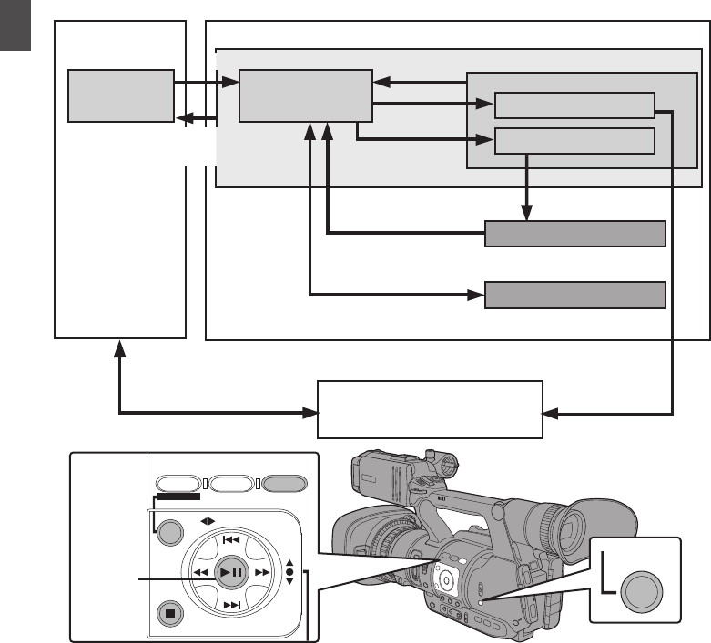
Operation Modes
This camera recorder has three operation modes - Camera mode, Media mode, and USB mode.
.
AE LEVEL
MENU/THUMB
FOCUS ASSIST/1 OIS / 2 LOLUX / 3
CANCEL
TIME CODE
MODE
Playback
Button
Trimming Playback
Normal Playback
[CANCEL]/[MENU/THUMB] Button
Camera Input
Connection to PC with
USB Cable
Press and hold [MODE]
[MODE]
Button
(Actions)
Execute [Delete Clips] File Deletion in Progress
Exit/Cancel File Delete Operation (Successful/Failed/Stopped)
Trimming in Progress
Exit Trimming Operation
(Successful/Failed/Stopped)
[LOLUX/3] Button
Execute
[Trim This Clip]
Media Mode
Thumbnail Display
USB Connection (When the confirmation to change
to USB mode appears and [Change] is selected)
(USB Mass Storage Class)
USB Mode
Playback
Button
Connection disabled on PC
Camera Mode
Playback
14 Operation Modes
Introduction

Operation Mode Description
Camera Mode 0This is the camera shooting mode. The camera recorder starts up in Camera mode
when the power is turned on.
0Camera images are output on the viewfinder and LCD monitor. When a recordable
SD card is inserted, the camera recorder enters the recording standby mode.
“STBY” appears on the operation mode display area of the LCD monitor and
viewfinder.
0Press the [REC] trigger button to start recording.
Memo :
0Playback of SD card is not possible in Camera mode. However, you can check the
most recently recorded video clip.
(A P66 [Viewing Recorded Videos Immediately (Clip Review)] )
Media Mode 0This mode allows you to play back or delete clips recorded on the SD card.
0When a playable SD card is inserted, the thumbnail or playback screen is displayed
on the viewfinder and LCD monitor.
0Press the [MODE] selection button to enter Media mode when you are not shooting
in Camera mode. Once the camera recorder is in Media mode, thumbnails of the
selected media slot are displayed.
USB Mode 0This mode allows you to connect to a PC and transfer the files on an SD card to
the PC.
0When the camera recorder is connected to a USB cable, the message “Change to
USB Mode?” appears.
Select [Change] and press the Set button to switch to USB mode.
(A P124 [Loading Clips to the PC] )
0In USB mode, the camera recorder is recognized by the connected PC as a
peripheral drive. (USB mass storage class only)
Disable the connection on the PC and remove the USB cable from the camera
recorder to switch to Camera mode.
(A P124 [Loading Clips to the PC] )
Memo :
0When a USB cable is connected during recording, the message appears after
recording stops.
0If playback is in progress, the message appears once the files are closed
automatically, such as when playback stops.
0Files on the PC cannot be written to the SD card.
Operation Modes 15
Introduction

Names of Parts
.
FOCUS ZOOM
REC
H
E
IJ
G
DACB
K
F
FIX VAR OFF
FOCUS ASSIST/1
OIS/2 LOLUX/3
MENU/THUMB
AE LEVEL
FOCUS
SCENE SELECT
B
A
OFF
POWER
MARKER/6
ZEBRA/5
AE LOCK/4
SHUTTER
WHT BAL
CANCEL
LOCK
IRIS
GAIN
FULL AUTO
PUSH AUTO
REC
PRESET
B
L
M
H
A
ON
OFF
ON
MANU
∞
MODE
OFF
SLOT
A/B
TIME CODE
AUTO
Bottom
ABuilt-in Microphone
(A P57 [Audio Recording] )
BTally Lamp
(A P34 [Tally Lamp] )
(A P128 [Blinking of the Tally Lamp] )
CMicrophone Holder
(A P23 [Attaching an External Microphone] )
DMicrophone Holder Lock Knob
(A P23 [Attaching an External Microphone] )
EShoe
For mounting separately sold lights and
accessories.
F[FIX/VAR/OFF] Zoom Speed Switch
(A P43 [Zoom Operation] )
For switching the zoom speed of the zoom lever
a at the handle.
GAccessory Mounting Screw Hole
HTripod Mounting Hole
(A P23 [Attaching the Tripod] )
I[REC] Record Trigger Button
Starts/stops recording.
You can also change its function in the menu.
(A P90 [ Front REC ] )
Memo :
0This button is interlocked with the [REC] button
R on the grip and the [REC/HOLD] button Z at
the top of the handle.
J[FOCUS/ZOOM] Operation Switch
For focus operation using the Focus/Zoom ring,
set the [FOCUS/ZOOM] operation switch to
“FOCUS”. For zoom operation, set it to
“ZOOM”.
(A P43 [Zoom Operation] )
(A P45 [Focus Operation] )
KMonitor Speaker
(A P79 [Audio Output during Playback] )
LViewfinder
(A P32 [Adjusting the LCD Monitor and
Viewfinder] )
MVisibility Adjustment Lever
(A P32 [Adjusting the LCD Monitor and
Viewfinder] )
NEyecup
Prevents external light from entering the
viewfinder screen and cameraman’s vision.
OBattery
(A P24 [Using a Battery Pack] )
P[x] Headphone Jack (Φ3.5 mm)
(A P59 [Monitoring Audio Sound During
Recording Using a Headphone] )
Q[AUX] AUX Input Terminal (Φ3.5 mm)
For connecting to receiver such as wireless
microphone.
16 Names of Parts
Introduction

.
AUX
INPUT2 INPUT1
DEVICE
AV
A
BATT.RELEASE
POWER
/CHG
B
HDMI
REMOTE
DC
REC
W
T
REC
HOLD
IN OUT
TC
L
M
N
O
d
RS T
X
Za
b
c
Q
P
U
V
Y
W
R[REC] Record Trigger Button
Starts/stops recording.
Memo :
0This button is interlocked with the [REC] button
I at the bottom of the lens and the [REC/
HOLD] button Z at the top of the handle.
S[C.REVIEW/7] Clip Review/User 7 Button
For checking the most recently captured
images.
(A P66 [Viewing Recorded Videos
Immediately (Clip Review)] )
You can also use it as a user button by assigning
a specific feature in the menu setting to this
button.
(A P34 [Assignment of Functions to User
Buttons] )
TZoom Lever at the Grip
(A P43 [Using the Zoom Lever at the Grip] )
U[TC] TC Input/Output Terminal
(A P60 [Time Code and User’s Bit] )
V[IN/OUT] TC IN/OUT Selection Switch
(A P64 [Synchronizing Time Code on
Another Camera] )
WHood Release Button
(A P24 [Attaching/Detaching the Hood] )
XExternal Microphone Cable Clamp
(A P23 [Attaching an External Microphone] )
Y[INPUT1/INPUT2] Audio Input Terminal 1, 2
(XLR 3-pin x 2)
(A P23 [Attaching an External Microphone] )
Z[REC/HOLD] Record Trigger Button/Lock
Switch
Starts/stops recording.
Set the switch to [HOLD] to lock the [REC]
Trigger button.
Memo :
0This button is interlocked with the [REC] button
R on the grip and the [REC] button I at the
bottom of the lens.
0The [REC] button R on the grip and the [REC]
button I at the bottom of the lens will not be
locked.
aZoom lever at the Handle
(A P43 [Using the Zoom Lever at the
Handle] )
bShoulder Belt Mount (x2)
For mounting a shoulder belt (sold separately).
Caution :
0Be sure to use a shoulder belt with the strength
to withstand the weight of this camera recorder.
0If the shoulder belt is not properly attached, the
camera recorder may fall and cause injuries.
Check the instruction manual provided with the
shoulder belt before using.
c[POWER/CHG] Power/Charging Display Lamp
(A P24 [Using a Battery Pack] )
d[BATT. RELEASE] Battery Lock Release Button
(A P25 [Removing the Battery] )
Names of Parts 17
Introduction
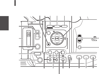
Side Control Panel
.
SCENE SELECT
FOCUS
LOCK
AE LEVEL
MANU
AUTO
MENU/THUMB
FOCUS ASSIST/1 OIS / 2 LOLUX / 3
B
A
OFF
PRESET
IRIS
GAIN
CANCEL
L
M
H
B
A
WHT BAL SHUTTER
FULL AUTO
MODE
POWER
ON
OFF
ON
OFF
AE LOCK/4 ZEBRA/5 MARKER/6
PUSH AUTO
TIME CODE
AUTO
A
B
C
E
S R Q
O
N
MLKJ
T
D
P
H
I
U
F G
A[FOCUS AUTO / MANU / BAUTO] Focus
Switch
(A P45 [Focus Operation] )
B[SCENE SELECT] Scene Selection Switch
(A P48 [Using Scene Select] )
C[LOCK] Auto Focus Lock Button
D[IRIS] Iris Auto/Manual Selection Button
(A P50 [Adjusting the Iris] )
E[PUSH AUTO] Iris Push Auto Button
(A P50 [Adjusting the Iris] )
F[GAIN] Gain Auto/Manual Selection Button / [L/
M/H] Sensitivity Selection Switch
(A P51 [Setting the Gain] )
G[WHT BAL] White Balance Auto/Manual
Selection Button / [B/A/PRESET] Selection
Switch
(A P53 [Adjusting the White Balance] )
H[SHUTTER] Shutter Speed Auto/Manual
Selection Button
(A P52 [Setting the Electronic Shutter] )
I[y] One Push Auto White Balance Button
J[FULL AUTO ON/OFF] Full Auto Switch
For switching the Full Auto mode to ON/OFF.
Full Auto mode adjusts the Iris, Gain, Shutter
and White Balance automatically.
(A P50 [Adjusting the Brightness
Automatically] )
(A P50 [Auto Iris (Automatic Adjustment)
Mode] )
(A P51 [Automatic Gain Mode (Automatic
Gain Adjustment)] )
(A P52 [Automatic Shutter Mode (Automatic
Shutter Adjustment)] )
(A P53 [Automatic White Balance Mode
(FAW: Fulltime Auto White balance)] )
K[AE LOCK/4] AE Lock/User 4 Button
When Gain, Iris, and Shutter are set to “AUTO”,
their respective values and the value of white
balance are locked when the [AE LOCK/4] button
is pressed.
You can also use it as a user button by assigning
a specific feature in the menu setting to this
button.
(A P34 [Assignment of Functions to User
Buttons] )
L[ZEBRA/5] Zebra/User 5 Button
(A P65 [Setting Zebra Pattern] )
You can also use it as a user button by assigning
a specific feature in the menu setting to this
button.
(A P34 [Assignment of Functions to User
Buttons] )
M[MARKER/6] Marker/User 6 Button
This button toggles ON/OFF the marker, safety
zone, and center mark displays.
You can also use it as a user button by assigning
a specific feature in the menu setting to this
button.
(A P34 [Assignment of Functions to User
Buttons] )
N[MODE] Camera/Media Mode Selection Button
(A P14 [Operation Modes] )
O[POWER ON/OFF] Lock Power ON/OFF Switch
Turns ON/OFF the power.
0Hold down the lock button (blue) in the center
to toggle ON/OFF.
0When the power is turning OFF, “P.OFF”
appears on the LCD monitor and viewfinder.
0Wait for 5 seconds or more to turn on the
power again.
PCross-Shaped Button (JKHI)/Set Button (R)
The function changes according to the
operation status of the camera recorder.
oDuring menu operation (all modes)
(A P85 [Basic Operations in Menu Screen] )
Set Button (R):Confirms menu items
and setting values
Cross-shaped Button
(JK)
:Selects menu items
and setting values
oDuring Camera mode
Shutter operation:
Set Button (R):Shutter ON/OFF
Cross-shaped Button
(JK)
:Switches shutter
speed when shutter
is ON
Cross-Shaped Button
(HI)
:AE level operation
Q[LOLUX/3] Low-light Shooting/User 3 Button
For switching the low-light shooting mode ON
or OFF.
You can also use it as a user button by assigning
a specific feature in the menu setting to this
button.
(A P34 [Assignment of Functions to User
Buttons] )
18 Names of Parts
Introduction

R[OIS/2] Optical Image Stabilizer/User 2 Button
For switching the image stabilizer feature mode
ON or OFF.
You can also use it as a user button by assigning
a specific feature in the menu setting to this
button.
(A P34 [Assignment of Functions to User
Buttons] )
S[FOCUS ASSIST/1] Focus Assist/User 1 Button
For switching the focus assist function ON or
OFF.
(A P46 [Focus Assist Function] )
You can also use it as a user button by assigning
a specific feature in the menu setting to this
button.
(A P34 [Assignment of Functions to User
Buttons] )
T[MENU/THUMB] Menu/Thumbnail Button
0Displays the menu screen during Camera
mode.
0Switches between [Main Menu] and
[Favorites Menu] when the [MENU/THUMB]
button is pressed and held down while the
menu screen is displayed.
(A P85 [Basic Operations in Menu Screen] )
0Displays the menu screen when the button is
pressed during thumbnail display in the
Media mode.
0Stops playback and displays the thumbnail
screen when the button is pressed during
playback screen display in the Media mode.
U[CANCEL] Cancel Button
Cancels various settings and stops playback.
SD Slot
(A P35 [SD Card] )
.
A
B
C
D
ASD Card Cover
B[SLOT A/B] Card Slot Selection Button
For switching the active card slot during
shooting and playback.
CCard Slot B Status Indicator
DCard Slot A Status Indicator
Rear Terminal
.
DEVICE
AV
HDMI
REMOTE
DC
POWER
/CHG
BATT.RELEASE
A
B
OPEN
CLOSE
AV
DEVICE
DC
REMOTE
C
B
A
D
E
A[DEVICE] USB Mini Terminal
(A P124 [Loading Clips to the PC] )
B[AV] AV Output Terminal
(A P125 [Connecting External Monitor] )
C[HDMI] HDMI Output Terminal
(A P125 [Connecting External Monitor] )
D[REMOTE] Remote Terminal
(A P126 [Connecting Wired Remote Control] )
E[DC] DC Input Terminal
Input terminal for DC 12 V power supply. For
connecting with the supplied AC adapter.
(A P26 [Using AC Power (DC IN Power)] )
Names of Parts 19
Introduction
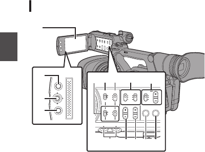
LCD Monitor
.
MENU/THUMB
CANCEL
CH1
INT
INPUT1
INPUT2
AUTO
MANUAL
CH2
INPUT2
MONITOR
DISPLAY STATUS
INPUT1
PEAKINGLCD BRIGHT
CH2CH1
LINE
MIC
MIC
+48V
CH1
BOTH
CH2
B
C
H I
A
D
FG
E
JKL
NM
ALCD Monitor
(A P32 [Adjusting the LCD Monitor and
Viewfinder] )
B[MENU/THUMB] Menu/Thumbnail Button
0Displays the menu screen during Camera
mode.
0Switches between [Main Menu] and
[Favorites Menu] when the [MENU/THUMB]
button is pressed and held down while the
menu screen is displayed.
(A P85 [Basic Operations in Menu Screen] )
0Displays the menu screen when the button is
pressed during thumbnail display in the
Media mode.
0Stops playback and displays the thumbnail
screen when the button is pressed during
playback screen display in the Media mode.
CLCD Cross-Shaped Button (JKHI)/Set Button
(R)
The function changes according to the
operation status of the camera recorder.
0During menu operation (all modes)
(A P85 [Basic Operations in Menu Screen] )
Set Button (R) : Confirms menu
items and setting
values
Cross-shaped Button
(JK)
: Selects menu
items and setting
values
0During Camera mode
You can also use it as a user button by assigning
a specific feature in the menu setting to this
button.
(A P34 [Assignment of Functions to User
Buttons] )
D[CANCEL] Cancel Button
Cancels various settings and stops playback.
E[CH1/CH2] CH1/CH2 Recording Level
Adjustment Knob
(A P57 [Audio Recording] )
F[LCD BRIGHT +/-] LCD Display Brightness
Adjustment Button
(A P32 [Adjusting the Brightness] )
G[PEAKING +/-] LCD/VF Contour Adjustment
Button
(A P33 [Adjusting the Contour (LCD)] )
(A P33 [Adjusting the Contour (Viewfinder)] )
H[DISPLAY] Display Button
0Press the [DISPLAY] button to switch to the
display screen during normal screen display
(when the menu screen is not displayed).
(A P30 [Display Screen] )
0Switches between [Main Menu] and
[Favorites Menu] when the [DISPLAY] button
is pressed while the menu screen is
displayed.
(A P85 [Basic Operations in Menu Screen] )
I[STATUS] Status Screen Display Button
Press the [STATUS] button to display the status
screen on the viewfinder and LCD monitor
during normal screen display (when the menu
screen is not displayed).
(A P31 [Status Screen] )
J[MONITOR]/[+/-] Audio Monitor Selection
Switch/Volume Adjustment Button
Switches the audio monitor and adjusts the
monitor speaker/headphone.
(A P59 [Monitoring Audio Sound During
Recording Using a Headphone] )
K[INPUT1/INPUT2] Audio Input Signal Selection
Switch
(A P57 [Audio Recording] )
L[CH2] CH2 Audio Input Signal Selection Switch
Select the audio input terminal to record to CH2.
(A P57 [Audio Recording] )
M[CH1] CH1 Audio Input Signal Selection Switch
(A P57 [Audio Recording] )
N[CH1/CH2 AUTO/MANUAL] CH1/CH2 Audio
Recording Mode Switch
(A P58 [Adjusting Audio Recording Level] )
20 Names of Parts
Introduction

Lens Section
.
D
C
A
B
AFilter Built-In Screw
0Transparent or UV filter for lens protection, or
filters for various effects can be installed.
0Installable filter types: φ46mmP0.75
Memo :
0Remove the lens hood when installing the filter.
(A P24 [Attaching/Detaching the Hood] )
BLens Cover Open/Close Switch
(A P23 [Opening/Closing the Lens Cover] )
CFocus/Zoom Ring
(A P45 [Focus Operation] )
(A P43 [Zoom Operation] )
For focus operation using the Focus/Zoom ring,
set the [FOCUS/ZOOM] operation switch to
“FOCUS”. For zoom operation, set it to
“ZOOM”.
DIris Dial
(A P50 [Adjusting the Iris] )
To operate auto iris, press the [IRIS] button on
the side control panel.
(a mark appears on the screen)
Names of Parts 21
Introduction
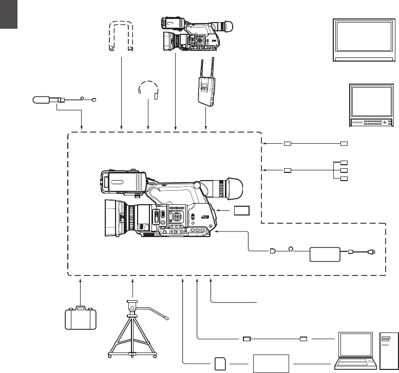
Basic System Diagram
.
Wireless Microphone Receiver
RCA pin
AV Cabl e
HDMI Cable
Carrying Case
Tr i p o d
SDHC/SDXC
Memory Card
SDHC/SDXC
Card Reader
USB Cable
Battery
AC Adapter
Remote Control Unit
Non-linear Editing
System
JY-HM360
Microphone
Monitor
Monitor
Headphone
Shoulder Belt JY-HM360
Standard Package
[AUX]
[INPUT1]/
[INPUT2] [TC]
[HDMI]
[AV]
[DC]
[x]
22 Basic System Diagram
Introduction

Settings and Adjustments
Before Use
.
Adjusting the Grip Belt
Open the pad and adjust the position of the grip belt
accordingly.
.
AUX
INPUT2 INPUT1
DEVICE
AV
A
BATT.RELEASE
POWER
/CHG
B
HDMI
REMOTE
DC
REC
Caution :
0If the grip is loose, the camera recorder may fall
off resulting in injuries or malfunction.
Attaching an External Microphone
You can attach a separately sold microphone to the
microphone holder.
.
4
5
1, 3
2
1Turn the knob on the microphone holder
counterclockwise to loosen and open the
microphone holder.
2Place the microphone in the microphone
holder.
3Turn the knob on the microphone holder
clockwise to secure the microphone.
4Connect the microphone cable to the
[INPUT1] or [INPUT2] terminal.
5Pin the microphone cable to the clamp.
6Perform the settings for the microphone
correctly.
(A P57 [Audio Recording] )
Attaching the Tripod
Use the screw hole at the bottom of this camera
recorder.
(3/8×16UNC, 1/4×20UNC)
Use the screw hole that suits the tripod.
To prevent the camera recorder from falling off,
which may result in injuries or damages, read the
“INSTRUCTIONS” of the tripod to be used and
make sure that it is securely attached.
.
o Bottom
Caution :
0If the camera recorder exceeds the weight limit
of the tripod, do not mount it on the tripod.
0Use the tripod on a stable surface.
0To prevent the camera recorder from falling,
attach securely using the rotation prevention
hole.
0Use screws with screw length 5 mm and below.
Opening/Closing the Lens Cover
Use the lens cover open/close switch to open or
close the lens cover.
Before shooting, open the lens cover.
When this camera recorder is not in use, close the
lens cover to protect the lens.
.
Caution :
0Do not press against the lens cover with force.
Doing so may damage the lens or the cover.
Settings and Adjustments Before Use 23
Preparations
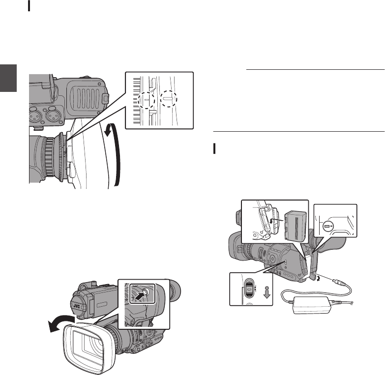
Attaching/Detaching the Hood
Attaching the Hood
Align the markings on the camera recorder and
hood; turn the hood in the direction of the arrow until
it is locked.
.
Detaching the Hood
0Remove the hood when attaching a filter,
teleconverter or wide converter to the front of the
lens.
0While pressing the hood release button, turn the
hood in the direction of the arrow (anti-
clockwise) to remove it.
.
TIME CODE
Power Supply
To use this camera recorder, you can attach a
battery pack or connect an AC adapter to it.
(A P24 [Using a Battery Pack] )
(A P26 [Using AC Power (DC IN Power)] )
Caution :
0Set the [POWER ON/OFF] switch to “OFF”
before changing the power supply that operates
this camera recorder.
0This product does not come with a battery pack.
When using a battery, please purchase the
recommended battery pack (SSL-JVC50).
Using a Battery Pack
Charging the Battery
Charge the battery immediately after purchase or
when the battery power is running low.
.
1
2
3
4
4
POWER
/CHG
MODE
POWER
ON
OFF
1
Hold down the lock button (blue) at the
center of the [POWER ON/OFF] switch to set
to “OFF”.
2Attach the battery.
Slide it in until you hear a click.
3Connect the supplied AC adapter to the
[DC] terminal.
Open the cover of the [DC] terminal and connect
as shown in the diagram.
4Connect the AC adapter to a power outlet.
0The [POWER/CHG] lamp blinks during
charging and will go out after charging is
complete.
0Remove the AC adapter after charging is
complete.
24 Settings and Adjustments Before Use
Preparations

Memo :
0Blinking of the [POWER/CHG] lamp during
charging indicates the charge level.
[POWER/CHG] Lamp Charge Level
Orange blinking
(4 times per second)
Less than 25 %
Orange blinking
(3 times per second)
Less than 50 %
Orange blinking
(2 times per second)
Less than 75 %
Orange blinking
(1 time per second)
Less than 100 %
Light goes out Fully charged
0You can charge the battery even when operating
the camera recorder using the AC adapter.
Removing the Battery
.
1
2
MODE
POWER
ON
OFF
1
Hold down the lock button (blue) at the
center of the [POWER ON/OFF] switch to set
to “OFF”.
2While pressing and holding the [BATT.
RELEASE] button, push up and remove the
battery in the direction of the arrow.
Caution :
0Do not remove the battery when the [POWER
ON/OFF] switch is “ON”.
0Do not insert or remove the DC cable when the
battery is in use.
0Leaving the camera recorder unused with the
battery inside will deplete the battery power
even if you set the [POWER ON/OFF] switch to
“OFF”. Remove the battery if you are not using
the camera recorder.
Estimated Charging and Continuous
Operating Times
oCharging time
Approx. 4 hrs (SSL-JVC50)
* When the [POWER ON/OFF] switch is set to
“OFF”
Memo :
0If you charge the battery immediately after using
while the battery is still warm, it may not be fully
charged.
0For details, refer to the “INSTRUCTIONS” of the
battery.
oContinuous operating time
Approx. 6 hrs (SSL-JVC50)
Memo :
0Actual operating times may differ depending on
the age of the battery, charging condition, and
operating environment.
0Operating time is shortened in cold
environment.
0The operating time may shorten when power
zoom is used, accessories are connected, or
when the LCD monitor is frequently used.
0For purchase of spare batteries and battery
charger, please contact the local dealers in your
area.
Precautions for Batteries
0Store the battery in a cool and dry place when
not in use. Do not expose the battery to high
temperatures (such as in a car under direct
sunlight). Failure to do so not only shortens the
battery life but also damages the battery.
0If the operating time shortens drastically even
after charging, the battery may be reaching the
end of its life. Replace the battery with a new
one.
Power Supply 25
Preparations
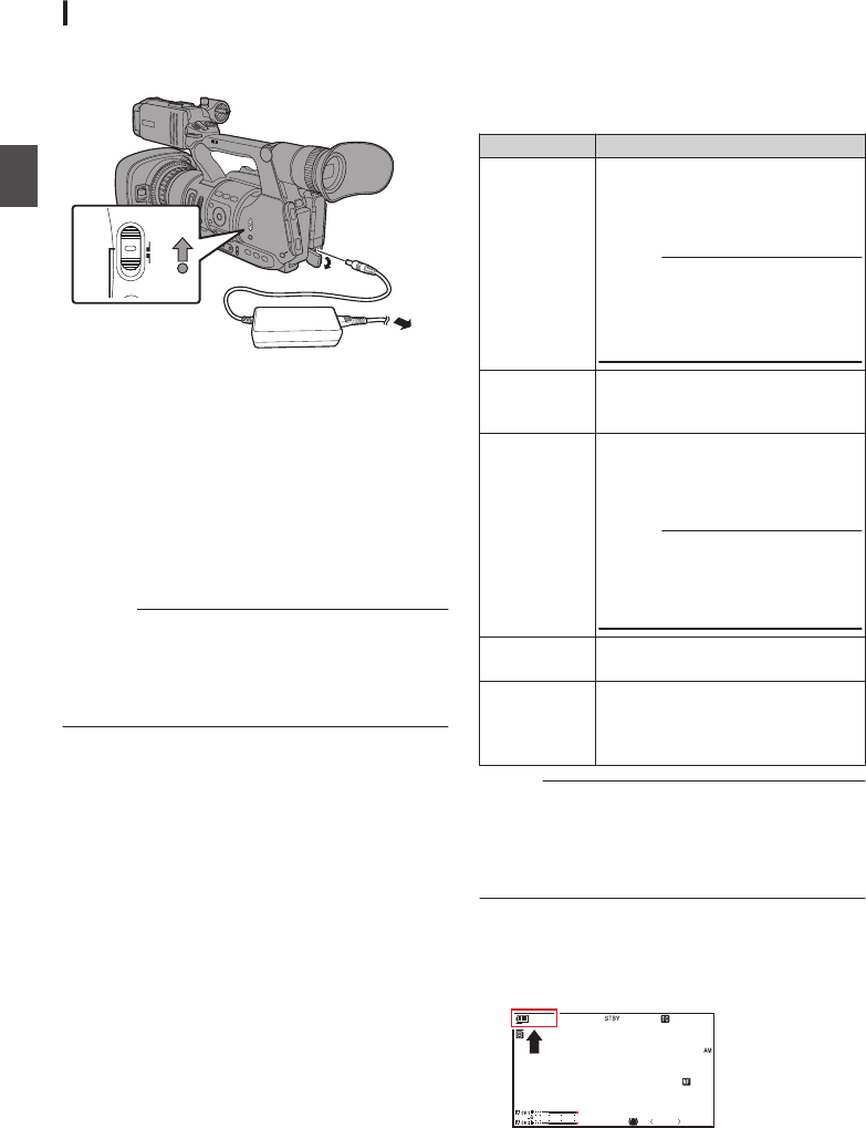
Using AC Power (DC IN Power)
Use the supplied AC adapter to operate the camera
recorder with AC power.
.
1
MODE
POWER
ON
OFF
2
1Connect the DC cable of the AC adapter to
the [DC] terminal of the camera recorder.
0Check that the power switch of the camera
recorder is set to “OFF”.
0Open the cover of the [DC] terminal and
connect as shown in the diagram.
2
Hold down the lock button (blue) at the
center of the [POWER ON/OFF] switch to set
to “ON”.
Power will be supplied to the camera recorder.
Caution :
0Do not insert or remove the DC cable during
recording.
0Do not use power supply of high voltage
fluctuation, containing noise such as ripple, or
with insufficient capacity.
Charging the Built-In Battery
0The date/time and time code data are stored
using the built-in rechargeable battery.
0When power is connected to the camera
recorder, the built-in battery always gets
charged. When the power is disconnected, the
battery gradually discharges.
0The battery will be totally discharged if left
unused for 3 months and the date/time and time
code data will be reset. When this happens, set
the [POWER ON/OFF] switch to “ON” to display
the [Initial Setting] screen, then set the date/
time.
(A P28 [Initial Settings] )
Power Status Display
Viewfinder Screen and LCD Monitor
The power status is displayed on the display and
menu screens.
Display Description
B 7.4V
B 100min
C 30%
4 RES
Currently powered by a battery.
When the battery power runs out,
the battery mark appears hollow,
and “RES” (yellow) is displayed.
Memo :
0You can set the display using
[LCD/VF] B [Display Settings]
B [Battery].
(A P99 [ Battery ] )
FAcquisition of battery information
may fail if a recommended battery
is not used.
TAn error has occurred during
battery charging; the charging
function is not working or charging
has been interrupted.
Memo :
0If the error appears, turn off the
power and remove the battery
then reinsert the battery and
turn the power on again.
GCurrently powered by an AC
adapter.
P
Q
R
S
Camera recorder battery charging
in progress.
(A P99 [Details on charging
condition] )
Memo :
0If the battery in use is not a recommended one,
the battery mark which indicates the battery
level may not appear.
0The charging function may not work depending
on the usage condition.
Display Screen
(A P112 [Display Screen in Camera Mode] )
(A P116 [Display Screen in Media Mode] )
.
100min
50min
282min
P13000K 1/ 100
F1 . 6
0dB
AE+6
5 . 6 f t
12 : 34 : 56
Jan 1 2, 2016
00: 00 : 00.00
1920x1080
60 i HQ
4030 20 10 0
26 Power Supply
Preparations

Menu Screen
(A P86 [Display and Description of the Menu
Screen] )
.
Warnings by Lamp and Warning Tone
Warning status is indicated by tally lamp and
warning tone.
0The tally lamp blinks.
0The warning tone is output from the monitor
speaker or [x] terminal.
Memo :
0You can specify whether to turn on the warning
tone as well as setting the volume in [A/V Set] B
[Audio Set] B [Alarm Level].
(A P103 [ Alarm Level ] )
0If you continue to use the camera recorder while
the power warning is displayed, the camera
recorder will stop automatically when the battery
or supplied voltage from the AC adapter
becomes lower.
Caution :
0The remaining battery power and time are
displayed as they are from the battery
information. Accurate data may not be displayed
depending on the battery condition. Replace the
battery as soon as possible when the remaining
battery power and time are low.
Turning On/Off the Power
Turning On the Power
1
Hold down the lock button (blue) at the
center of the [POWER ON/OFF] switch to set
to “ON”.
The camera recorder starts up in Camera mode
and is ready for shooting.
Memo :
0The camera recorder always start up in Camera
mode when the [POWER ON/OFF] switch is set
to “ON”. Use the [MODE] button at the side of
the camera recorder to switch mode.
(A P14 [Operation Modes] )
.
TIME CODE
MODE
POWER
ON
OFF
Turning Off the Power
Sets the camera recorder to the recording standby
or stop mode.
1
Hold down the lock button (blue) at the
center of the [POWER ON/OFF] switch to set
to “OFF”.
2Remove the battery and the power to the
[DC] terminal (when not in use for a long
time).
Auto Power Off function
When [System] B [Auto Power Off] is set to “On”,
the power turns off automatically when the camera
recorder is not operated for 5 minutes or longer
while running on battery.
(A P104 [ Auto Power Off ] )
Memo :
0When both the battery and AC adapter are
connected, power from the AC adapter
connection will be used. As such, the [Auto
Power Off] function will not have any effect.
Caution :
0Do not set the [POWER ON/OFF] switch to
“OFF” during recording. Check that the
operation mode display is “STBY” or “STOP”
before you turn off the power.
0If you have mistakenly set the [POWER ON/
OFF] switch to “OFF” during recording, wait for
5 seconds or more before you turn on the power
again.
0When turning off the power, first set the
[POWER ON/OFF] switch of the camera
recorder to “OFF”. Do not remove the battery or
turn off the AC power while the [POWER
ON/OFF] switch is set to “ON”.
Power Status Display 27
Preparations
Initial Settings
When the power is first turned on, the Initial Setting
screen for performing the initial settings in the
camera recorder appears.
Set the date/time of the built-in clock in the [Initial
Setting] screen.
All operations are disabled until initial settings are
complete.
.
TIME CODE
MODE
POWER
ON
OFF
AE LEVEL
MENU/THUMB
CANCEL
MENU/THUMB
CANCEL
Memo :
0It is recommended to use the AC adapter as the
power supply.
0Be sure to close the lens cover.
1
Hold down the lock button (blue) at the
center of the [POWER ON/OFF] switch to set
to “ON”.
A language selection screen appears.
.
Memo :
0The menus and messages on the screen of the
LCD monitor or viewfinder are displayed in the
selected language.
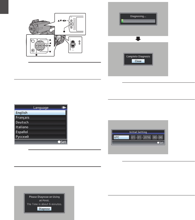
2Select a language using the cross-shaped
button (JK), and press the Set button (R).
The Initial Setting screen appears.
.
3Ensure that the lens cover is closed, and
press the Set button (R).
0Self-diagnosis starts.
0A progress bar appears, and “Complete
Diagnosis” appears when the diagnosis is
complete.
.
Memo :
0It takes about 6 minutes to complete the
diagnosis. During the diagnosis, do not operate
or turn off the camera recorder.
4Press the Set button (R) after confirming
the exit screen.
The [Initial Setting] screen appears.
.
Memo :
0The [Initial Setting] screen appears when the
power is turned on for the first time and when the
power is turned on after the built-in battery is fully
discharged.
0The configured date/time data is saved in the
built-in rechargeable battery even if the power is
turned off.
28 Initial Settings
Preparations

5Set the time zone and date/time.
AMove the cursor with the cross-shaped button
(HI) and select the setting item.
BChange the values with the cross-shaped
button (JK).
6Press the Set button (R) after setting is
complete.
The clock is set to 0 seconds of the input date/
time.
Memo :
0The configured date/time data can be displayed
on the LCD monitor and viewfinder and be
recorded to the SD card.
0The value of the year can be set in the range of
“2000” to “2099”.
Changing the Time after Initial Setting
Setting the Date/Time
(A P104 [ Date/Time ] )
1Select [System] B [Date/Time].
The [Date/Time] screen appears.
2Set the date and time.
AMove the cursor with the cross-shaped button
(HI) and select the setting item.
BChange the values with the cross-shaped
button (JK).
3Press the Set button (R) after setting is
complete.
The clock is set to 0 seconds of the input date/
time.
Changing the Display Style
You can change the display style of the date/time
on the menu.
Setting the Date Display (Date Style)
(A P99 [ Date Style ] )
The date display can be changed in [LCD/VF] B
[Display Settings] B [Date Style].
Setting the Time Display (Time Style)
(A P99 [ Time Style ] )
The time display can be changed in [LCD/VF] B
[Display Settings] B [Time Style].
Date/Time Display in Each Operation
Mode
During Camera mode:
Date/time of the built-in clock is displayed.
During Media mode:
Shooting date/time of the clip being played back is
displayed.
Initial Settings 29
Preparations

Displays on the LCD
Monitor and Viewfinder
You can display the camera status, media
information, zebra pattern, and various markers in
the video image on the LCD monitor and viewfinder
screen during shooting.
Memo :
0When [Main Menu] B [A/V Set] B [Video Set]
B [Display On TV] is set to “On”, the display
screen and menu screen are also displayed in
the video image from the video signal output
terminal.
(A P100 [ Display On TV ] )
Display Screen
Display Screen (VF/LCD) in Camera Mode
(A P112 [Display Screen in Camera Mode] )
0The display switches between three screen
types with every press of the [DISPLAY] button.
(Display 0 B 1 B 2 B 0)
0Press the [STATUS] button to switch to the
status screen.
.
Display 2 screen
Display 1 screen
Display 0 screen
100min
50min
282min
P13000K 1/100
F1 . 6
0dB
AE+6
12 : 34 : 56
Jan 12, 2016
00:00:00.00
1920x1080
60 i HQ
4030 20 10 0
5 . 6 f t
P13000K 1/100
F1 . 6
0dB
AE+6
12 : 34 : 56
Jan 12, 2016
00:00:00.00
4030 20 10 0
5 . 6 f t
Display Screen (VF/LCD) in Media Mode
(A P116 [Display Screen in Media Mode] )
0This is the screen display during clip playback in
Media Mode.
0The display switches between three screen
types with every press of the [DISPLAY] button.
(Display 0 B 1 B 2 B 0)
.
1000/ 2000
12 : 34 : 56
Jan 12,2016
00: 00: 00.00
1920x1080
60 i HQ
4030 20 10 0
1000/ 2000
282min
12 : 34 : 56
Jan 1 2,2016
00: 00: 00.00
1920x1080
60 i HQ
4030 20 10 0
1000/ 2000
x5
SELECT
x5
Display 2 screen
Display 1 screen
Display 0 screen
30 Displays on the LCD Monitor and Viewfinder
Preparations
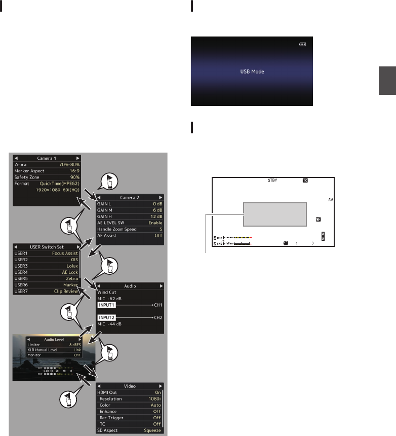
Status Screen
0This screen allows you to check the current
settings.
0To display the status screen, press the
[STATUS] button in the normal screen.
0The status display differs according to the
operation mode (two types).
(A P14 [Operation Modes] )
0Press the [STATUS] button to switch to the
display screen.
0Press the [MENU/THUMB] button at each status
screen (other than the [Camera 1]/[Camera 2]
screen) to enter the setting screen.
0Use the cross-shaped button (HI) to switch
screens as follows:
.
* These are screen examples. The contents
displayed are different depending on the
settings.
USB Mode Screen
This screen displays the USB mode.
.
Warning Display
Warning display is displayed in the display screen
(Camera mode, Media mode).
(A P127 [Error Messages and Actions] )
.
P13000K 1/100
F1. 6
0dB
AE+6
5 . 6 f t
12 : 34 : 56
Jan 12, 2016
00:00: 00.00
4030 20 10 0
Warning Display Area
Displays on the LCD Monitor and Viewfinder 31
Preparations

Adjusting the LCD Monitor
and Viewfinder
You can monitor video images on this camera
recorder using the viewfinder, LCD monitor, or
both.
.
DISPLAY
Normal LCD
Inverted
LCD
Displays on the LCD Monitor and
Viewfinder Screen (VF)
When [LCD/VF] B [LCD + VF] is set to “Off”
(A P96 [ LCD + VF ] )
LCD Monitor Status LCD Display VF Display
LCD closed Normal LCD OFF ON
Inverted LCD ON OFF *
LCD opened Normal LCD ON OFF *
Inverted LCD ON OFF *
* Turns on when [LCD/VF] B [LCD + VF] is set to
“On”.
Memo :
0
Press and hold the [DISPLAY] button for 2 seconds
to turn ON/OFF the LCD monitor.
0
The function to switch between LCD monitor and
viewfinder displays by pressing the [DISPLAY]
button can be canceled by opening/closing or
rotating the LCD monitor.
0
The viewfinder screen is always displayed when
[LCD/VF]
B
[LCD + VF] is set to “On”.
0
You can display both the LCD monitor and
viewfinder screens at the same time by setting
[LCD/VF]
B
[LCD + VF] to “On”.
(A P96 [ LCD + VF ] )
Adjusting the LCD Monitor
.
2
1
PEAKINGLCD BRIGHT
3
Tilt 90 degrees
downward
Tilt 180 degrees
upward
1Open the LCD cover.
2Incline the LCD monitor to a position that
enables easy viewing.
Rotate the LCD monitor to adjust the angle.
0While the LCD monitor is open, you can
rotate it 180 degrees upward or 90 degrees
downward.
0Rotating the LCD monitor 180 degrees
upward enables you to see the screen from
the lens side. To display the image when it is
viewed from the opposite direction (mirror
image), perform setting as follows.
Set [Main Menu] B [LCD/VF] B [LCD
Mirror] to “Mirror” B Set button (R)
(A P96 [ LCD Mirror ] )
3Adjust the brightness, contour, and
contrast of the LCD monitor.
You can change the angle and brightness of the
LCD monitor according to your usage condition.
Changing the brightness of the screen will not
affect the recorded images.
Adjusting the Brightness
Use the [LCD BRIGHT +/-] button to adjust the
brightness of the LCD monitor.
0The [+] button brightens the monitor and the
[-] button darkens it.
0Press the [+] and [-] buttons simultaneously
to return to standard settings.
0During adjustment, the brightness level is
displayed on the LCD monitor.
.
P13000K 1/100
F1. 6
0dB
AE+6
4030 20 10 0
LCD BRIGHT -10
32 Adjusting the LCD Monitor and Viewfinder
Preparations
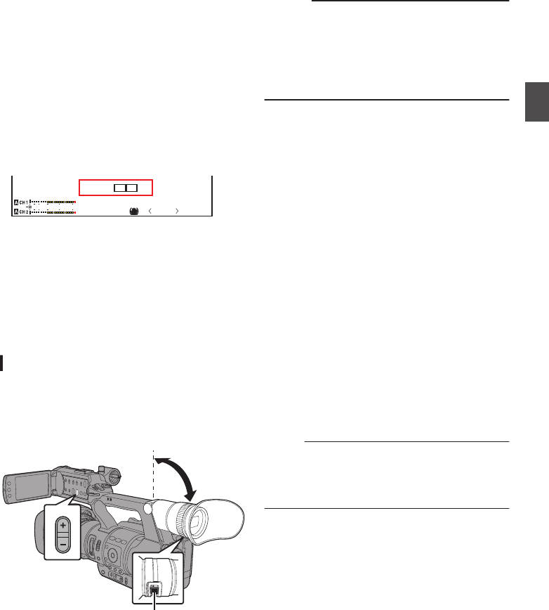
Adjusting the Contour
Use the [PEAKING +/-] button to adjust the
contour of the LCD monitor.
(The contour of the viewfinder screen will also
be adjusted at the same time.)
0The [+] button increases contour correction
and the [-] button decreases contour
correction.
0Press the [+] and [-] buttons simultaneously
to return to standard settings.
0During adjustment, the contour level is
displayed on the LCD monitor.
.
P13000K 1/100
F1. 6
0dB
AE+6
4030 20 10 0
PEAKING 0
Adjusting the Contrast
Use the [LCD Contrast] menu to adjust the
contrast of the LCD monitor.
0Adjust using [Main Menu] B [LCD/VF] B
[LCD Contrast].
0Increasing the value increases the contrast.
[Setting Values: +10 to -10] (Default value: 0)
Adjusting the Viewfinder
You can change the brightness and peaking of the
viewfinder screen according to your usage
conditions.
Changing the brightness of the screen will not
affect the recorded images.
.
PEAKING
1
2
Caution :
0A high-definition viewfinder is used on this
camera recorder in order to provide an accurate
focusing environment. Due to the characteristic
of the display device, colors may appear on the
images when you blink your eyes. This is not a
malfunction. It does not affect the recorded
images, VIDEO output, or HDMI output.
1Incline the viewfinder vertically to a
position that enables easy viewing.
2Turn the visibility adjustment lever to
adjust the visibility.
Turn the visibility adjustment lever to sharpen
the image on the viewfinder screen.
3Adjust the brightness, contour, and
contrast of the viewfinder screen.
Adjusting the Brightness
Use the [VF Bright] menu to adjust the
brightness of the viewfinder screen.
0Adjust using [Main Menu] B [LCD/VF] B [VF
Bright].
0Increasing the value increases the
brightness. [Setting Values: +10 to -10]
(Default value: 0)
Adjusting the Contour
Use the [PEAKING +/-] button to adjust the
contour of the viewfinder screen.
The contour of the LCD monitor will also be
adjusted at the same time.
(A P33 [Adjusting the Contour] )
Memo :
0When [Main Menu] B [LCD/VF] B [LCD + VF] is
set to “Off”, operate after switching to the
viewfinder display by pressing the [DISPLAY]
button for 2 seconds or longer.
Adjusting the Contrast
Use the [VF Contrast] menu to adjust the
contrast of the viewfinder screen.
0Adjust using [Main Menu] B [LCD/VF] B [VF
Contrast].
0Increasing the value increases the contrast.
[Setting Values: +10 to -10] (Default value: 0)
Adjusting the LCD Monitor and Viewfinder 33
Preparations
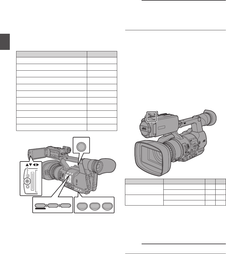
Assignment of Functions
to User Buttons
You can assign functions to the following buttons
and use them as user buttons.
By assigning functions to the buttons, the usability
of the camera recorder can be enhanced.
Perform settings in the menu items corresponding
to each button.
Button Menu Item
[FOCUS ASSIST/1] Button [USER1]
[OIS/2] Button [USER2]
[LOLUX/3] Button [USER3]
[AE LOCK/4] Button [USER4]
[ZEBRA/5] Button [USER5]
[MARKER/6] Button [USER6]
[C.REVIEW/7] Button [USER7]
LCD Cross-Shaped Button (J) [LCD KEY▲]
LCD Cross-Shaped Button (K) [LCD KEY▼]
LCD Cross-Shaped Button (H) [LCD KEY◀]
LCD Cross-Shaped Button (I) [LCD KEY▶]
.
MENU/THUMB
CANCEL
AE LOCK/4 ZEBRA/5 MARKER/6
FOCUS ASSIST/1 OIS / 2 LOLUX / 3
TIME CODE
C.REVIEW/7
1Assign functions to the buttons from the
menu.
Set items in [Main Menu] B [Camera
Function] B [User Switch Set] B [USER1]-
[USER7], [LCD KEY▲], [LCD KEY▶], [LCD
KEY▼], [LCD KEY◀].
(A P90 [User Switch Set Item] )
Memo :
0Operations of the user buttons are interlocked
with the menu settings.
0When the menu screen is displayed, these
buttons function as the menu operation buttons.
(A P85 [Basic Operations in Menu Screen] )
Tally Lamp
This is the indicator lamp for recording and
warning.
The operation changes according to the menu
settings.
The lamp blinks when the battery or remaining
space on the SD card is low. (Camera mode only)
* Set using [Main Menu] B [System] B [Tally
Lamp].
(A P104 [ Tally Lamp ] )
.
TIME CODE
Menu Setting Tally Lamp Off On
Functional
information
Warning - J
Caution - o
Recording status Recording - R
Special recording * - R
R:Lights up
J:Blinks four times in 1 second
o:Blinks once in 1 second
* Paused state during special recording ([Clip
Continuous]).
(A P72 [Clip Continuous Rec] )
Memo :
0Blinking takes priority over lighting up.
34 Assignment of Functions to User Buttons
Preparations

SD Card
This camera recorder saves the recorded images
and audio sound on the SD card (sold separately)
in the card slot.
Usable Cards
Use a Class 6/10 SD card.
Memo :
0Depending on the recording format, SD card
with Class 4 or higher performance can also be
used.
(A P42 [Selecting System Definition, File
Format and Video Format] )
0To use an SDHC card, set [4GB File
Spanning(SDXC)] to “On”.
(A P107 [ 4GB File Spanning(SDXC) ] )
Caution :
0Using cards other than those from Panasonic,
TOSHIBA or SanDisk may result in recording
failure or data loss.
Estimated Recordable Time of SD Cards
The estimated recordable time is only a guide.
Differences may occur depending on the SD card
in use and the battery condition.
(A P105 [ Resolution ] )
(A P105 [ Frame & Bit Rate ] )
QuickTime/MP4
MPEG2/HD
SP HQ
1080i 720p/1080i
4 GB 17 12
8 GB 35 25
16 GB 70 50
32 GB 140 100
64 GB
(SDXC)
280 200
128 GB
(SDXC)
560 400
(Unit: minute)
AVCHD
HQ HQ SP LP EP
1080p 1080i
4 GB 16 19 25 46 82
8 GB 33 39 50 95 168
16 GB 67 78 100 190 336
32 GB 135 156 200 380 672
64 GB
(SDXC)
270 312 400 760 1344
128 GB
(SDXC)
540 624 800 1520 2688
(Unit: minute)
QuickTime
H.264/HD H.264/SD
XHQ UHQ -
1080i/1080p 1080i 576i
4 GB 9 12 47
8 GB 18 25 95
16 GB 36 50 190
32 GB 72 100 380
64 GB
(SDXC)
145 200 760
128 GB
(SDXC)
290 400 1520
(Unit: minute)
Memo :
0If the SD card contains files recorded by devices
other than this camera recorder or files that are
saved from a PC, the recordable time may be
shorter or data may not be properly recorded.
0The number of clips that can be recorded to one
SD card on this camera recorder for each file
format is restricted.
Up to 600 clips can be recorded for the
“QuickTime” file format and 4000 clips for the
“AVCHD” file format. When the maximum
number of clips is reached, the remaining space
is displayed as “0 min” regardless of the
estimated recordable time, and no further
recording can be made.
Write-Protect Switch on the SD Card
ASlide the write-protect switch upward to enable
writing or deleting.
BSlide the write-protect switch downward to
prevent writing or deleting. (Images in the card
are protected.)
.
AB
Write/Delete Enabled Write/Delete Disabled
Write-Protect Switch
SD Card 35
Preparations

Inserting an SD Card
This camera recorder comes with two card slots
(Slot A and B) for video/audio recording and
playback.
.
1
2
3
1
A
B
2
1Open the SD card cover.
2Insert an SD card with the notched corner
pointing up.
The status indicator of the card slot to which the
card was inserted lights up in red.
3Close the SD card cover.
Card Slot Status Indicator
The following table shows the respective states of
slot A and B.
Lamp Slot Status
Lights up in
red
The inserted SD card is being
accessed. (writing/reading data)
Do not turn off the power of the
camera recorder or remove the SD
card.
Lights up in
green
On standby. The inserted SD card
can be used for recording or
playback.
Light goes out 0SD card is not inserted.
0An unusable card is inserted.
0An SD card is inserted but a
different slot is selected.
Removing the SD Card
1Check that the SD card to be removed is not
being accessed (status indicator of the
card slot lights up in red).
2Open the SD card cover.
3Push the SD card and remove it from the
slot.
4Close the SD card cover.
Memo :
0When both slots are inserted with usable SD
cards, the previously selected slot is used.
Caution :
0Data may be lost if you turn off the power of the
camera recorder or remove the SD card when it
is being accessed. All data recorded on the
card, including the file that is being accessed,
may be corrupted. Be sure to check whether the
status indicator is lit in green or turned off before
you turn off the power or remove the SD card.
0If you mistakenly remove the card when it is
being accessed, reinsert the card only after the
status indicator goes off.
0The SD card may not be recognized if you insert
and remove the card within a short time. When
this happens, remove the card and wait for a few
seconds before you reinsert.
36 SD Card
Preparations

Switching the SD cards
When both card slots are inserted with SD cards,
you can use the [SLOT A/B] button to switch the
card to use.
When the memory on an SD card is full during
recording, data recording automatically switches to
the other card.
.
AE LEVEL
MENU/THUMB
CANCEL
MENU/THUMB
CANCEL
SLOT
A/B
Memo :
0The [SLOT A/B] button is disabled during
recording or playback. Cards will not be
switched even if you press the button.
Formatting (Initializing) SD Cards
When the following cards are inserted, [!FORMAT]
appears at the remaining media display area.
Format the card using the camera recorder menu.
0Unformatted SD cards
0SD cards formatted under different
specifications
* For details of the menu operation, refer to
“[Basic Operations in Menu Screen]
(A P 85)”.
Caution :
0Be sure to format the SD card on this camera
recorder. SD cards formatted on a PC and other
peripheral equipment cannot be used on this
camera recorder.
0[!RESTORE] appears at the remaining media
display area when an SD card that requires
restoring is inserted.
1Select [System] B [Media] B [Format
Media].
(A P103 [ Format Media ] )
2Select the slot of the SD card to be
formatted and press the Set button (R).
.
2
3The status of the selected SD card appears.
4Select [Format] and press the Set button
(R).
.
4
5Formatting starts.
.
SD Card 37
Preparations

6Formatting is complete.
When formatting is complete, “Complete” appears
and the camera recorder returns to the [Format
Media] screen.
Memo :
0During formatting, menu operation is
unavailable but you can start recording.
However, this is only available when a
recordable SD card is inserted in the other slot.
0Formatting cannot be performed in the following
cases.
0Recording is in progress on the SD card to be
formatted.
0SD card is not inserted.
0Write-protect switch of the SD card is set (z
is displayed).
Caution :
0If you format the SD card, all data recorded on
the card, including video data and setup files,
will be deleted.
Restoring the SD Card
It is necessary to restore the SD card if an
abnormality occurs to the data in the card due to
some reasons.
Memo :
0[!RESTORE] appears at the remaining media
display area when an SD card that requires
restoring is inserted.
1Select [System] B [Media] B [Restore
Media].
(A P103 [ Restore Media ] )
2Select the SD card to be restored and press
the Set button (R).
.
2
3Restoring starts.
.
4Restoring is complete.
0When restoring is complete, “Complete”
appears and the camera recorder returns to the
[Restore Media] screen.
0When no media that requires restoring is
inserted, the camera recorder returns to the
[Media] menu screen.
Caution :
0[Restore Media] can only be selected in Camera
mode. However, it cannot be selected while the
camera recorder is recording. Select [Restore
Media] in Camera mode when the camera
recorder is not recording.
0[Restore Media] does not restore the SD card to
its original states completely. If restoring fails,
replace or format the SD card. Take note that
formatting erases all the information inside the
SD card.
0Restoring cannot be performed in the following
cases.
0Camera recorder is recording in progress.
0SD card is not inserted.
0Write-protect switch of the SD card is set (z
is displayed).
38 SD Card
Preparations

Clips Recorded to SD Cards
Folders in the SD Card
Images recorded are sorted into the respective
folders according to the menu settings below.
* Select which folder to record to from the menu.
(A P107 [ Recording in DCIM Folder ] )
System Format Record Folder
HD QuickTime
(MPEG2)
DCIM or PRIVATE/JVC/
CQAV*
MP4(MPEG2) PRIVATE/JVC/BPAV
AVCHD PRIVATE/AVCHD
HD/SD
QuickTime(H.264)
DCIM or PRIVATE/JVC/
CQAVC*
Memo :
0By formatting (initializing) the SD card from the
[Format Media] menu on the camera recorder,
folders required for recording in the current
[System] settings will be generated.
0When the [System] settings and
[QuickTime(MPEG2)] settings are changed,
folders required for recording in those settings
will be automatically generated.
Caution :
0When a clip inside the folder is moved or deleted
using the Explorer (Windows) or Finder (Mac),
recording to the SD card may fail if formatting
(initializing) of the card is not performed.
Clip (Recorded Data) and Clip Name
0When recording is stopped, the images, audio
and accompanying data which are recorded
from start to stop are recorded as one “clip” on
the SD card.
0An 8-character clip name is automatically
generated for the recorded clip.
(“Clip Name Prefix” + “Clip Number”)
0When [Main Menu] B [System] B [Record
Set] B [Record Format] B [Format] is set to
“AVCHD”, the clip name generated consists of
only the Clip Number (5-digit number).
(A P105 [ Format ] )
Example: In the case of QuickTime/MP4
.
ABCG0001
This is set to “xxxG” (“xxx” denotes the last 3
digits of the serial number) by default.
Clip Name Prefix (any four alphanumeric characters)
The Clip Number can be reset in
the menu.*
A number in automatic
ascending order is assigned in
the recording order.
Clip Number
* [Clip Set] B [Reset Clip Number]
(A P107 [ Reset Clip Number ] )
Memo :
0Before recording starts, you can set any
characters for the clip name prefix by using
[Main Menu] B [System] B [Record Set] B [Clip
Set] B [Clip Name Prefix].
(A P107 [ Clip Name Prefix ] )
0Changes cannot be made after recording.
Recorded Clips
0The recorded materials may be split into several
files but they can be played back continuously
on the camera recorder.
0Clips may be recorded across the two SD cards
in card slots A and B depending on the recording
time of the clip.
Caution :
0A clip recorded across several cards cannot be
played back continuously. Continuous playback
is only possible when the recording is made on
one card.
SD Card 39
Preparations

Operation Lock Feature
You can use this feature to prevent erroneous
camera operation.
.
AE LEVEL
MENU/THUMB
CANCEL
1While in the Camera mode (when the
display screen appears), press and hold
the [CANCEL] button for 5 seconds or
longer.
0The operation lock turns on, and an operation
lock icon (r) appears on the display
screen.
.
P 13000K 1/100
F1. 6
0dB
AE+6
00:00: 00.00
4030 20 10 0
0Press the [CANCEL] button again for 5
seconds or longer to turn off the operation
lock.
Memo :
0The operation lock feature is only valid in the
Camera mode.
(A P14 [Operation Modes] )
0The power turns off and the operation lock is
disengaged.
0The [CANCEL] button on the LCD monitor
section cannot be used to turn on/off (“On/Off”)
the operation lock feature.
0The following remote operations are possible
even when the operation lock feature is turned
on (“On”).
0Remote operation from the wired remote
control connected to the [REMOTE] terminal.
0Remote operation of the camera through
access via a browser on devices such as a
smartphone, tablet terminal, or PC.
Operation lock does not apply to the following
buttons and switches.
0[POWER ON/OFF] switch
0TC [IN/OUT] selection switch
0All switches inside the LCD monitor door
(however, the operation of the [CH1/CH2]
adjustment knob will be locked.)
0Zoom Lever at the Grip
0Zoom Lever at the Handle
0Focus/Zoom Ring
0[FOCUS/ZOOM] Operation Switch
0[FIX/VAR/OFF] zoom speed switch
0Iris Dial
0[REC] button (at the top of the handle, on the grip
and at the bottom of the lens)
Memo :
0The operation lock will also not apply to the
[REC] button at the bottom of the lens if [Camera
Function] B [User Switch Set] B [Front REC] is
set to “Rec”.
40 Operation Lock Feature
Preparations
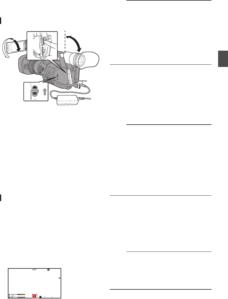
Basic Shooting
Procedures
Preparations
.
31
MODE
POWER
ON
OFF
4
24
1Supply battery or AC adapter power to the
camera recorder.
(A P24 [Power Supply] )
2Insert an SD card.
(A P35 [SD Card] )
3Turn on the power of the camera recorder.
Hold down the lock button (blue) at the center of
the [POWER ON/OFF] switch to set to “ON”. The
camera recorder starts up in Camera mode and
is ready for recording.
4Adjust the angle of the LCD monitor and
viewfinder.
(A P32 [Adjusting the LCD Monitor and
Viewfinder] )
Shooting
1Configure the video and audio input
settings.
0Set the [FULL AUTO ON/OFF] switch to “ON”
to enter Full Auto mode. This mode adjusts
the Iris, Gain, Shutter and White Balance
automatically.
0The audio recording level is also set to Auto,
and audio from the built-in microphone is
recorded in the Full Auto mode.
0The a icon appears at the lower center area
of the LCD in the Full Auto mode.
.
AE+6
12 : 34 : 56
Jan 12, 2016
00: 00 : 00.00
4030 20 10 0P13000K
Memo :
0To set each individual video setting item
automatically or manually, and to carry out the
audio input settings and the audio recording
level adjustment, refer to the following.
0[Adjusting the Brightness] (A P 50)
0[Adjusting the Iris] (A P 50)
0[Setting the Gain] (A P 51)
0[Setting the Electronic Shutter] (A P 52)
0[Adjusting the White Balance] (A P 53)
0[Adjusting Audio Recording Level]
(A P 58)
2Press the [REC] button to start recording to
the SD card.
This camera recorder has three [REC] buttons.
Any of the [REC] buttons can be used to start/
stop recording by default.
The tally lamp lights up in red during recording.
0Zoom Operation
(A P43 [Zoom Operation] )
0Adjusting the Focus
(A P45 [Focus Operation] )
Memo :
0If both the slots are loaded with recordable cards
in the factory default, pressing the [REC] button
starts recording only to the media in the selected
slot.
When [Main Menu] B [System] B [Record Set]
B [Slot Mode] is set to “Dual”, recording can be
performed simultaneously to the cards in both
the slots.
(A P68 [Dual Rec] )
0The tally lamp can be turned off in [System] B
[Tally Lamp].
(A P104 [ Tally Lamp ] )
3Check the most recently captured images.
0Press the [C.REVIEW/7] button on the lens to
activate the Clip Review function. The most
recently captured images are played back on
the LCD monitor and viewfinder screen.
0After playback, the camera recorder returns
to standby mode (STBY).
(A P66 [Viewing Recorded Videos
Immediately (Clip Review)] )
Memo :
0[Clip Review] is assigned to [C.REVIEW/7]
button in factory default.
0[Clip Review] can also be assigned to other user
buttons.
(A P34 [Assignment of Functions to User
Buttons] )
Basic Shooting Procedures 41
Shooting

Selecting System
Definition, File Format and
Video Format
You can select the system definition (HD or SD),
file format for recording/playback and the record
format for video images on this camera recorder.
Memo :
0Make a selection in [Main Menu] B [Record
Format].
Selecting a System Definition
The following definitions are available for selection.
0HD:
Records in HD (High Definition) quality.
0SD:
Records in SD (Standard Definition) quality.
You can select a definition for the recorded images
from the following items under [System].
0HD:
Records in HD quality for both slots A and B.
0SD:
Records in SD quality for both slots A and B.
Selecting a File Format
Select a file format in [Format].
The following file formats are available for
selection.
0QuickTime(MPEG2):
QuickTime file format (.MOV)
0MP4(MPEG2):
MP4 file format
0AVCHD:
AVCHD file format
0QuickTime(H.264):
QuickTime format (.MOV)
Memo :
0The available options vary as follows depending
on the [System] setting.
0For “HD”:
QuickTime(MPEG2), MP4(MPEG2),
AVCHD,QuickTime(H.264)
0For “SD”:
QuickTime(H.264)
Selecting a Video Format
0Select a [Record Format] from the list of formats.
The selectable [Frame & Bit Rate] changes
according to the settings of [System], [Format],
and [Resolution].
0The recording bit rate (video) is 50 Mbps in
“XHQ”, 35 Mbps VBR in “UHQ” and “HQ”, and
18.3 Mbps (25 Mbps in the case of 1080i) CBR
in “SP”.
0The recording bit rate (system rate) is as follows
when [Format] is set to “AVCHD”.
0“HQ” (60p/50p): 28 Mbps VBR
0“HQ” (60i/50i): 24 Mbps VBR
0“SP”: 18 Mbps VBR
0“LP”: 9 Mbps VBR
0“EP”: 5 Mbps VBR
List of Formats
The following is a list of file formats and video
formats that can be selected on this camera
recorder.
0When [System] is set to “HD”
Record Format
Format
Resolution
Frame & Bit
Rate
MP4 (MPEG2)
QuickTime (MPEG2)
1920x
1080
60i (HQ)
50i (HQ)
1440x
1080
60i (HQ),
60i (SP) (*1)
50i (HQ),
50i (SP) (*1)
1280x
720
60p (HQ)
50p (HQ)
AVCHD
(*2)
1920x
1080
60p (HQ),
50p (HQ)
60i (HQ),
60i (SP)
50i (HQ),
50i (SP)
1440x
1080
60i (LP),
60i (EP)
50i (LP),
50i (EP)
QuickTime
(H.264)
1920x
1080
60p (XHQ),
50p (XHQ)
60i (XHQ),
60i (UHQ)
50i (XHQ),
50i (UHQ)
*1 HDV compatible
*2 Recordable using Class 4
0When [System] is set to “SD”
The video format is fixed as follows.
Record Format
Remarks
Format Resolution Frame &
Bit Rate
QuickTime
(H.264) 720 x 576 50i Recordable
using Class 4
42 Selecting System Definition, File Format and Video Format
Shooting
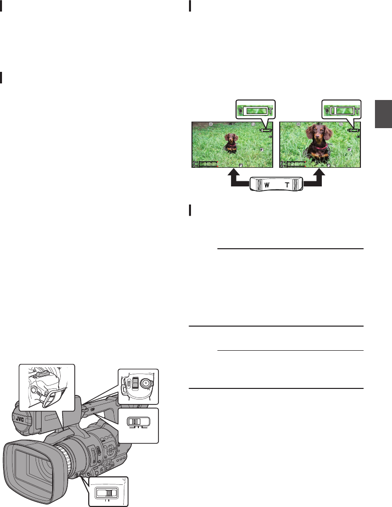
Selecting the Aspect Ratio of SD Videos
Select an aspect ratio for the images.
The available options vary as follows depending on
the [System] setting.
0For “HD”: Fixed at 16:9
0For “SD”: Can select 16:9 or 4:3
Setting the Record Format Menu
1Display the [Main Menu] B [Record
Format] menu.
2Set each of the items.
3After setting is complete for all items, press
the [FOCUS ASSIST/1] button.
0The recording format is switched.
0A “Please Wait...” message appears on the
screen during switching.
Zoom Operation
Adjusts the angle of view.
Optical zoom is 10 times.
Enable the dynamic zoom function to zoom up to
19 times.
Set the dynamic zoom “On”/“Off” in [Main Menu] B
[Camera Function] B [Dynamic Zoom].
(A P89 [ Dynamic Zoom ] )
Zooming can be operated using any of the three
levers/rings below.
0Zoom Lever at the Grip
0Zoom Lever at the Handle
0Focus/Zoom Ring:
To zoom in and out using the Focus/Zoom Ring,
set to “ZOOM”.
.
TIME CODE
W
T
REC
HOLD
REC
FIX VAR OFF
FOCUS ZOOM
Using the Zoom Lever at the Grip
1Press the zoom lever to zoom.
0The zoom speed changes according to the
extent the zoom lever is being pushed.
0Zooms into wide angle and increases the
angle of view when “W” is pressed.
0Zooms into telephoto and decreases the
angle of view when “T” is pressed.
0A zoom bar appears during zoom operation
.
P 13000K
P 13000K
1/100
1/100
F1.6
F1.6
0dB
0dB
AE+6
AE+6
12:34:56
12:34:56
Jan 12,2016
Jan 12,2016
00:00:00.00
00:00:00.00
40
40
30
30
20
20
10
10 0
5.
5.6 f t
P 13000K
P 13000K
1/100
1/100
F1.6
F1.6
0dB
0dB
AE+6
AE+6
12:34:56
12:34:56
Jan 12,2016
Jan 12,2016
00:00:00.00
00:00:00.00
40
40
30
30
20
20
10
10 0
5.
5.6 f t
Using the Zoom Lever at the Handle
1Set the [FIX/VAR/OFF] zoom speed switch
to “FIX” or “VAR”.
Memo :
0Setting to “FIX” will allow the zoom operation to
move at the speed set in [Handle Zoom Speed].
0Set the zoom speed using [Main Menu] B
[Camera Function] B [Handle Zoom Speed].
(A P89 [ Handle Zoom Speed ] )
0Setting to “VAR” will change the zoom speed
according to the pressure applied on the lever.
2Press the zoom lever at the handle to zoom.
Memo :
0When the [FIX/VAR/OFF] zoom speed switch is
set to “OFF”, the zoom lever at the handle
section cannot be used.
Selecting System Definition, File Format and Video Format 43
Shooting

Using the Focus/Zoom Ring
1Set the [FOCUS/ZOOM] operation switch to
“ZOOM”.
You can adjust the preferred angle of view by
turning the focus/zoom ring.
Saving/Recalling Current Zoom
Position (Preset Zoom)
This allows you to register up to three zoom
positions.
1Assign the “Preset Zoom1”, “Preset
Zoom2”, or “Preset Zoom3” function to any
of the user buttons.
(A P34 [Assignment of Functions to User
Buttons] )
(A P90 [USER1 to USER7, LCD KEY▲, LCD
KEY▶, LCD KEY▼, LCD KEY◀] )
2Save the current zoom position.
0Press any of the buttons assigned with the
“Preset Zoom1”, “Preset Zoom2”, or “Preset
Zoom3” function for more than 1 second.
0The current zoom position will be stored.
3Recall the stored zoom position.
0Press any of the buttons assigned with the
“Preset Zoom1”, “Preset Zoom2”, or “Preset
Zoom3” function and release within 1
second.
0The camera recorder zooms to the stored
zoom position.
Memo :
0The speed to zoom to the zoom position can be
set in [Main Menu] B [Camera Function] B [User
Switch Set] B [Preset Zoom Speed].
(A P91 [ Preset Zoom Speed ] )
0Operating other zoom maneuvers during a
zoom position recall will cancel the recall.
Focus Operation
.
TIME CODE
FOCUS
MANU
LOCK
FOCUS ASSIST/1
TIME CODE
AUTO
AUTO
ZOOMFOCUS
Adjusting Focus Automatically
Set the [FOCUS AUTO / MANU / BAUTO] focus
switch to “AUTO”.
There is no icon display in Auto Focus mode.
Memo :
0If [Main Menu] B [Camera Function] B [AF
Assist] is set to “Area” or “Far/Near”, you can turn
the focus/zoom ring to shift the auto focus point
while in the automatic focus adjustment mode.
(A P90 [ AF Assist ] )
0When face detection is enabled, the Auto Focus
icon e appears with the face mark.
(A P98 [ Focus ] )
One Push Auto Focus
While in the Manual Focus mode, pressing the
[FOCUS AUTO / MANU / BAUTO] focus switch to
“BAUTO” (within 1 minute) makes the camera
recorder focus on the center of the frame
automatically.
Memo :
0Face detection does not work during One Push
Auto Focus.
0AF Assist does not function.
0When the operation is complete, the camera
recorder returns to the Manual Focus mode
automatically.
0One Push Auto Focus functions with emphasis
on the focusing speed. This function is not
suitable during recording.
44 Zoom Operation
Shooting

Setting to Auto Focus Temporarily
(Push Auto Focus)
0The camera recorder will shift to Auto Focus
mode temporarily and automatically adjusts
focus when the [FOCUS AUTO / MANU /
BAUTO] focus switch is pressed to “BAUTO”
during shooting in Manual Focus mode.
0Release your finger from the [FOCUS AUTO /
MANU / BAUTO] focus switch to return to
Manual Focus mode.
Memo :
0Face detection does not work during Push Auto
Focus.
Locking the Auto Focus
The focus is locked at the current focus point during
auto focus when you press the [LOCK] Auto Focus
Lock button or the user button assigned with the
[Push AF/AF Lock] function.
d appears on the screen while auto focus is
locked.
Memo :
0Performing any focusing operation when the
focus is locked disengages the focus lock.
Adjusting Focus Manually
1Set the [FOCUS AUTO / MANU / BAUTO]
focus switch to “MANU”.
The manual focus icon d appears on the
screen.
.
P13000K 1/100
F1 . 6
0dB
AE+6
12 : 34 : 56
Jan 12, 2016
00:00:00.00
4030 20 10 0
5 . 6 f t
Memo :
0The d icon appears even when [Main Menu] B
[LCD/VF] B [Display Settings] B [Focus] is set
to “Off”.
(A P98 [ Focus ] )
2Set the [FOCUS/ZOOM] operation switch to
“FOCUS”.
3Turn the focus/zoom ring to adjust the
focus.
Memo :
0Using the Focus Assist or Expanded Focus
function makes it easier to focus.
(A P46 [Focus Assist Function] )
(A P46 [Expanded Focus Function] )
0While in Manual Focus mode, pressing the
[FOCUS AUTO / MANU / BAUTO] focus switch
to “BAUTO” will shift the camera recorder to the
One Push Auto Focus mode. Continue to hold
down to “BAUTO” to enter the Push Auto Focus
mode.
(A P44 [One Push Auto Focus] )
(A P45 [Setting to Auto Focus Temporarily
(Push Auto Focus)] )
AF Assist Function
During auto focus, you can shift the auto focus
point.
Set the [FOCUS/ZOOM] operation switch to
“FOCUS” and turn the focus/zoom ring to set the
focus point to the left, center, right, or near and far
directions.
0Set [Main Menu] B [Camera Function] B [AF
Assist].
0Far/Near:
This option allows you to shift the auto focus
point to near and far directions by turning the
focus/zoom ring during AF.
Focus is automatically adjusted to a focus
point near the position where the focus/zoom
ring stops turning.
0Area:
Selecting this option displays the icon in
the area.
Turning the focus/zoom ring during AF
displays the focus area on the left, center, and
right side for about 2 seconds. Turning the
focus/zoom ring within 2 seconds allows you
to move the orange frame to select the focus
area.
After selecting the area, focus is
automatically adjusted to a focus point near
the selected area.
.
P 13000K 1/100
F1 . 6
0
dB
00: 00: 00.00
4030 20 10 0
* The icons ( , , and ) change in
conjunction with the orange frame in the focus
area.
Memo :
0When [Face Detect] is set, “Area” is not
selectable.
Focus Operation 45
Shooting

Focus Assist Function
0When the [FOCUS ASSIST/1] button is pressed
during shooting, the focused area is displayed
in color. This enables easy and accurate
focusing.
0Select the color (blue, red or green) in the menu.
Memo :
0To adjust focus with the focus/zoom ring while
the Focus Assist function is in operation, set the
[FOCUS/ZOOM] operation switch to “FOCUS”,
or set [Main Menu] B [Camera Function] B [AF
Assist] B [Ring] to “Focus”.
(A P97 [ Ring ] )
0Select the display color in [Main Menu] B [LCD/
VF] B [Shooting Assist] B [Focus Assist] B
[Color].
(A P97 [ Color ] )
0If you use the zebra function and the Focus
Assist function at the same time, it may be
difficult to see the effect of the Focus Assist. In
this case, turn off the zebra function.
Setting Focus Assist Function to a User Button
You can assign the “Focus Assist” function to a user
button.
(A P34 [Assignment of Functions to User
Buttons] )
Expanded Focus Function
Magnifies the image at the center. Doing so
enables precise focus to be established easily.
1Assign the “Expanded Focus” function to
any of the user buttons.
(A P34 [Assignment of Functions to User
Buttons] )
(A P90 [USER1 to USER7, LCD KEY▲, LCD
KEY▶, LCD KEY▼, LCD KEY◀] )
2Press the user button that is assigned with
the “Expanded Focus” function.
0“EXPANDED” (yellow color) appears on the
screen, and the center part of the image is
enlarged.
0Pressing the user button again restores the
image to the original size.
.
P13000K 1/100
F1 . 6
0dB
AE+6
12 : 34 : 56
Jan 24,2012
00: 00: 00.00
4030 20 10 0
5 . 6 f t
EXPANDED
EXPANDED
EXPANDED
EXPANDED
Memo :
0To set the operation when the button is pressed,
go to [Main Menu] B [Camera Function] B [User
Switch Set] B [Expanded Focus].
(A P92 [ Expanded Focus ] )
0To adjust focus with the focus/zoom ring while
the Expanded Focus function is in operation, set
the [FOCUS/ZOOM] operation switch to
“FOCUS”, or set [Main Menu] B [Camera
Function] B [User Switch Set] B [Expanded
Focus] B [Ring] to “Focus”.
(A P92 [ Ring ] )
0This function can be used together with the
Focus Assist function. When the functions are
used together, the focus can be adjusted using
the focus/zoom ring in the Focus Assist or
Expanded Focus function.
0The magnification ratio varies with the format of
the record signals.
0Magnifying an image does not alter the size of
the recorded image.
0This function is unavailable when [Main Menu]
B [System] B [Record Set] B [Record Format]
B [System] is set to “SD”.
Adjusting the Focusing by
Face Detection
This function detects human faces and
automatically adjusts focus during Auto Focus.
It can also track moving objects.
When several faces are detected, you can select
one to focus on.
Memo :
0This function can also adjust the brightness
automatically according to the brightness of the
face detected.
(A P91 [ Face Detect ] )
.
AE LEVEL
MENU/THUMB
CANCEL
MENU/THUMB
CANCEL
46 Focus Operation
Shooting

1Assign the “Face Detect” function to any of
the user buttons.
(A P34 [Assignment of Functions to User
Buttons] )
2Focus the camera recorder on a person and
press the user button that is assigned with
“Face Detect”.
0When Face detection is enabled, the face
detection icon (q) appears.
0When [Main Menu] B [Camera Function]
B [User Switch Set] B [Face Detect] is set
to “AF”, “q e” appears.
0When [Main Menu] B [Camera Function]
B [User Switch Set] B [Face Detect] is set
to “AF&AE”, “q” appears on the left of the
AE level setting value. When the camera
recorder is in the Scene Select mode,
“q AE” appears.
0If you select the person nearest to the center
of the screen, an orange frame will appear on
his face.
0Focus will be automatically adjusted for the
selected person.
.
Detection Frame (Orange)
AE
AE
Memo :
0If the detection frame does not appear, make
sure that the [FOCUS AUTO / MANU / BAUTO]
focus switch is set to “AUTO”. Also, if [Face
Detect] is set to “AF&AE”, set at least one of the
iris, gain, and electronic shutter control items to
the automatic adjustment mode.
(A P50 [Adjusting the Brightness
Automatically] )
(A P50 [Auto Iris (Automatic Adjustment)
Mode] )
(A P51 [Automatic Gain Mode (Automatic
Gain Adjustment)] )
(A P52 [Automatic Shutter Mode (Automatic
Shutter Adjustment)] )
Selecting Specific Person from Several
Persons
1Hold down the user button that is assigned
with “Face Detect”.
0The camera recorder will enter face selection
mode and the face detection icon (q) will
blink.
0An orange frame will appear on the face of
the person nearest to the center of the
screen. Blue frames will appear on the faces
of others.
.
Detection Frame (Blue)
Detection Frame (Orange)
Blinking
2Select a specific person.
0Use the cross-shaped button (HIJK) to
select a person.
0An orange frame will appear on the face of
the selected person and focus will be
automatically adjusted.
.
Detection Frame (Blue)
Detection Frame (Orange)
3Press the Set button (R) to confirm the
person for face detection.
Memo :
0Press the [CANCEL] button to cancel the
selection.
0You can specify the detection sensitivity and the
operation speed after losing sight of the face
using [Main Menu] B [Camera Function] B
[User Switch Set] B [Face Detect] B [Sensitivity]
and [Hysteresis].
(A P91 [ Sensitivity ] )
(A P91 [ Hysteresis ] )
Adjusting the Focusing by Face Detection 47
Shooting

Using Scene Select
Changing Scene Select
Use the [SCENE SELECT] switch to change
camera settings easily and promptly according to
specific scenarios.
Set the [SCENE SELECT] switch to “A” or “B” to
enter the Scene Select mode. This allows the
camera recorder to enter a preset shooting mode.
.
SCENE SELECT
B
A
OFF
When the camera recorder is in the Scene Select
mode, “SCN A” or “SCN B” appears on the screen.
.
1/100
F1 . 6
0dB
AE+6
12 : 34 : 56
Jan 12, 2016
00: 00: 00.00
4030 20 10 0
5 . 6 f t
P13000K
Setting Scene Select
You can set different shooting modes for “A” and
“B” of the [SCENE SELECT] switch.
1Set the [SCENE SELECT] switch to “A” or
“B”.
The camera recorder switches to the desired
set position (“A” or “B”).
2Press the [MENU/THUMB] button.
The Scene Select setting menu appears.
.
Cursor
(Orange Frame)
Check Mark
3Select a shooting mode.
0Use the cross-shaped button (JKH I) to
move the orange cursor. Select icons for the
shooting mode and press the Set button (R).
0Icons being selected are indicated by a check
mark (P). Press the Set button again to
remove the check mark.
0When a check mark appears beside an icon,
select i (Adjust) and press the Set button to
display the Adjust screen. You can adjust the
selected shooting mode.
(A P49 [Detailed Settings for Shooting
Mode] )
4Press the [MENU/THUMB] button.
Returns to the normal screen.
Memo :
0The Scene Select mode operates regardless of
the [FULL AUTO ON/OFF] switch setting.
However, Full Auto mode will be “ON”.
0The status of the selected shooting mode can
be saved in both “A” and “B” of the [SCENE
SELECT] switch.
0If a check mark does not appear for “Bright”,
“Dark”, “Hi Contrast”, “Vivid” or “Sharp”, the
Adjust screen will not appear.
0When the Scene Select setting menu is
displayed, changing the [SCENE SELECT]
switch to “OFF” will close the Scene Select
setting menu and return to the normal screen.
0When the [SCENE SELECT] switch is set to “A”
or “B”, items in [Main Menu] B [Camera
Function] cannot be set.
0Settings for [AE Level] are disabled during the
Scene Select mode.
0Settings for [Camera Process] are disabled
during the Scene Select mode.
48 Using Scene Select
Shooting
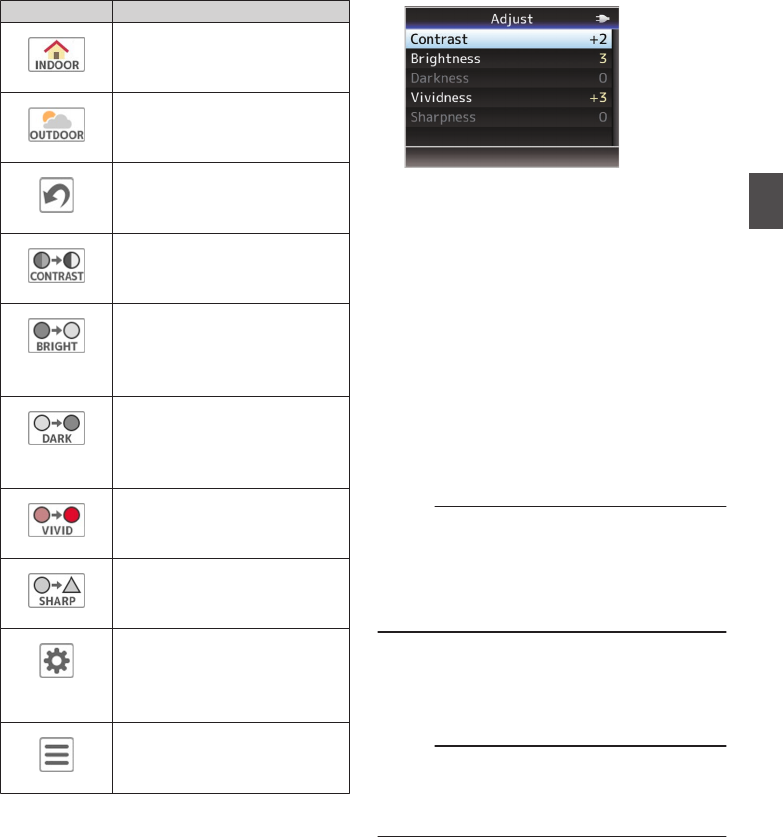
List of Shooting Modes (Icon)
Icon Description
.
Indoor (*1)
Select for indoor shooting.
.
Outdoor (*1)
Select for outdoor shooting.
.
(Reset)
Returns all current setting values
for the [SCENE SELECT] switch
(“A” or “B”) to default.
.
Hi Contrast
Select to add contrast and
differentiate brightness and
darkness.
.
Bright (*2)
Select when the background is
bright and the subject appears
dark against the backlight. Adjust
when the subject becomes darker
than necessary in Auto Iris mode.
.
Dark (*2)
Select when the background is
dark and the subject is too bright.
Adjust when the subject becomes
brighter than necessary in Auto
Iris mode.
.
Vivid
Select for shooting vivid and
colorful subjects.
.
Sharp
Select to emphasize the contour
of the subject.
.
(Adjust)
Displays the adjustment screen.
Details for each setting value can
be configured.
(A P49 [Detailed Settings for
Shooting Mode] )
.
(Menu)
Displays the menu screen.
(A P85 [Basic Operations in
Menu Screen] )
*1 “Indoor” and “Outdoor” cannot be selected at
the same time.
*2 “Bright” and “Dark” cannot be selected at the
same time.
Detailed Settings for Shooting Mode
.
1Adjust the setting values.
ASelect the item to adjust.
Select the item to adjust using the cross-
shaped button (JK), and press the Set
button (R).
BSelect the setting value.
Change the setting value using the cross-
shaped button (JK), and press the Set
button (R).
The settable items and their values are as
follows.
Contrast :-3 to +3 (Default value: +2)
Brightness : 0 to 6 (Default value: 3)
Darkness : 0 to 6 (Default value: 3)
Vividness : -5 to +5 (Default value: +3)
Sharpness : -3 to +3 (Default value: +2)
Memo :
0The default value is the one with the check mark
beside the icon in the Scene Select setting
menu.
0For items without a check mark beside the icons
in the Scene Select setting menu, the setting
values are fixed at “0” and cannot be changed.
2Press the crossed-shaped button (H) or
[CANCEL] button.
0Returns to the Scene Select setting menu.
0Press the [MENU/THUMB] button to return to
the normal screen.
Memo :
0When the Adjust screen is displayed, changing
the [SCENE SELECT] switch to “OFF” will close
the Adjust screen and return to the normal
screen.
Using Scene Select 49
Shooting
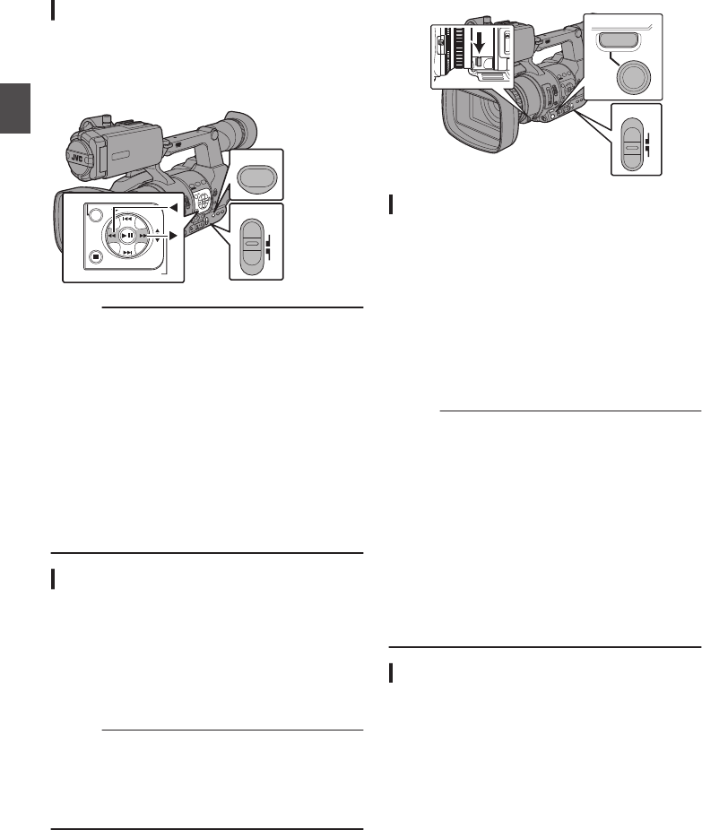
Adjusting the Brightness
Adjust the brightness using Iris, Gain and Shutter
speed according to the brightness of the object.
Adjusting the Brightness Automatically
When the [FULL AUTO ON/OFF] switch is set to
“ON”, Iris, Gain, Shutter speed and ND filter are
automatically adjusted according to the brightness
of the object to maintain optimum brightness.
.
FIX VAR OFF
AE LEVEL
LOCK
IRIS
∞
TIME CODE
FULL AUTO
ON
OFF
AE LEVEL
MENU/THUMB
GAIN
CANCEL
WHT BAL SHUTTER
AE LOCK/4
Memo :
0You can use the cross-shaped button (HI) on
the side of the camera recorder to set the target
level (brighter/darker) to maintain optimum
brightness during automatic adjustment.
(A P89 [ AE Level ] )
0The convergence speed of the automatic
adjustment for gain, shutter and iris can be set
in the menu.
(A P89 [ AE Speed ] )
0If one or more of the items (Gain, Iris and
Shutter) have been set to “Auto”, the value of the
corresponding items when the user button that
is assigned “AE Lock” is pressed can be fixed.
(A P91 [ AE Lock ] )
Adjusting the Brightness Manually
When the [FULL AUTO ON/OFF] switch is set to
“OFF” and [SCENE SELECT] switch is set to
“OFF”, some or all of the items (Iris, Gain and
Shutter Speed) can be manually adjusted.
(A P50 [Adjusting the Iris] )
(A P51 [Setting the Gain] )
(A P52 [Setting the Electronic Shutter] )
Memo :
0If Iris, Gain and Shutter Speed are manually
adjusted, the [AE Level] setting is temporarily
disabled.
0Settings for [AE Level] are disabled during the
Scene Select mode.
Adjusting the Iris
You can adjust the aperture of the lens iris manually
or automatically according to the brightness of the
object.
.
TIME CODE
IRIS
PUSH AUTO
FULL AUTO
ON
OFF
Auto Iris (Automatic Adjustment) Mode
1Set the [FULL AUTO ON/OFF] switch to
“OFF” to turn off the Full Auto mode.
2Set the [SCENE SELECT] switch to “OFF” to
turn off the Scene Select mode.
3Press the [IRIS] button to set to the Auto Iris
mode.
The iris is automatically adjusted according to
the brightness of the object.
The lens aperture value (F-number) is not
displayed in the Auto Iris mode.
Memo :
0Setting the [FULL AUTO ON/OFF] switch to
“ON” to enter Full Auto mode also activates the
Auto Iris mode. In this case, the Gain, Shutter
and White Balance also enter into Auto mode
forcibly.
The switching operation of the [IRIS] switch is
disabled in the Full Auto mode.
0You can use the cross-shaped button (HI) on
the side control panel to set the target level
(brighter/darker) of the auto iris.
(A P89 [ AE Level ] )
0The convergence speed of the auto iris can be
set in the menu.
(A P89 [ AE Speed ] )
Manual Iris (Manual Adjustment) Mode
The aperture value (F-number) of the lens can be
set manually.
1Set the [FULL AUTO ON/OFF] switch to
“OFF” to turn off the Full Auto mode.
2Set the [SCENE SELECT] switch to “OFF” to
turn off the Scene Select mode.
3Press the [IRIS] button to set to the Manual
Iris mode.
The lens aperture value (F-number) is
displayed.
50 Adjusting the Brightness
Shooting
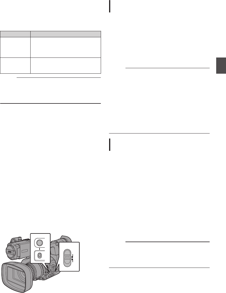
4Turn the iris dial to adjust the iris manually.
The open F-number of the aperture varies
according to the zoom position.
Wide [W] end : F1.2
Tele [T] end : F2.8
F-number Description
Decrease The subject appears brighter.
The focused range becomes
sharper, while the background is
blurred to produce a soft image.
Increase The subject appears darker.
Background of image becomes
focused as well.
Memo :
0Pressing the [PUSH AUTO] button during
Manual Iris mode activates One Push Auto Iris
mode. And holding down the [PUSH AUTO]
button activates Push Auto Iris mode.
One Push Auto Iris
When the camera recorder is in Manual Iris mode,
press the [PUSH AUTO] button to adjust the iris
according to the brightness of the object.
Push Auto Iris
When the camera recorder is in Manual Iris mode,
hold down the [PUSH AUTO] button to change to
Auto Iris mode temporarily. The iris will be
automatically adjusted according to the brightness
of the object.
Setting the Gain
This function electrically boosts the light sensitivity
when there is insufficient illumination on the object.
You can set the gain of the video amplifier
according to the brightness of the object. Select the
setting mode according to your shooting
conditions.
.
TIME CODE
GAIN
L
M
H
FULL AUTO
ON
OFF
Automatic Gain Mode (Automatic Gain
Adjustment)
1Set the [FULL AUTO ON/OFF] switch to
“OFF” to turn off the Full Auto mode.
2Set the [SCENE SELECT] switch to “OFF” to
turn off the Scene Select mode.
3Press the [GAIN] button to set to the
Automatic Gain mode.
The sensitivity value (in dB) will not be displayed
in the Auto Gain mode.
Memo :
0Set the [FULL AUTO ON/OFF] switch on the
camera recorder to “ON” to enter the Automatic
Gain mode ([AGC] fixed). The gain of the video
amplifier is automatically set according to the
brightness of the object.
In this case, the [GAIN] switch on the camera
recorder is disabled.
0The upper limit of the gain setting value during
AGC operation can be set in [Main Menu] B
[Camera Function] B [AGC Limit].
(A P89 [ AGC Limit ] )
Manual Gain Mode (Manual Gain
Switching)
1Set the [FULL AUTO ON/OFF] switch to
“OFF” to turn off the Full Auto mode.
2Set the [SCENE SELECT] switch to “OFF” to
turn off the Scene Select mode.
3Press the [GAIN] button to set to the Manual
Gain mode.
0Use the [L/M/H] switch to set the gain of the
selected video amplifier.
0The gain level appears on the screen.
0The default positions of the switch are as
follows.
[L] : 0dB
[M] : 6dB
[H] : 12dB
Memo :
0You can change the gain value of each position
in the menu. Increasing the sensitivity causes
the screen to appear grainier.
(A P89 [GAIN L, GAIN M, GAIN H] )
Adjusting the Iris 51
Shooting

Setting the Electronic
Shutter
You can change the shutter speed (time for each
shooting frame) using the electronic shutter
function. Electronic shutter can be adjusted
manually or automatically.
.
FIX VAR OFF
AE LEVEL
LOCK
IRIS
∞
TIME CODE
AE LEVEL
MENU/THUMB
GAIN
CANCEL
WHT BAL SHUTTER
FULL AUTO
ON
OFF
Automatic Shutter Mode (Automatic
Shutter Adjustment)
1Set the [FULL AUTO ON/OFF] switch to
“OFF” to turn off the Full Auto mode.
2Set the [SCENE SELECT] switch to “OFF” to
turn off the Scene Select mode.
3Press the [SHUTTER] button to set to the
Automatic Shutter mode.
0The shutter speed will not be displayed.
0The camera recorder enters the Automatic
Shutter mode. The shutter speed is
automatically adjusted according to the
brightness of the object.
Memo :
0Switching of shutter speed with the cross-
shaped button (JK) and switching of shutter
mode with the Set button (R) are disabled.
Manual Shutter Mode (Manual Shutter
Switching)
1Set the [FULL AUTO ON/OFF] switch to
“OFF” to turn off the Full Auto mode.
2Set the [SCENE SELECT] switch to “OFF” to
turn off the Scene Select mode.
3Press the [SHUTTER] button to set to the
Manual Shutter mode.
0The shutter speed appears on the screen.
0Use the Set button (R) to switch between the
shutter modes and the cross-shaped button
(JK) to switch between the speeds.
Switching Shutter Mode
Press the Set button (center of the cross-shaped
button) to turn ON/OFF the shutter.
Memo :
0When the shutter is ON, “Step” or “Variable” may
be selected in [Camera Function] B [Shutter].
“Step” is the factory default.
(A P89 [ Shutter ] )
Switching Shutter Speed
When Manual Shutter is activated, use the cross-
shaped button (JK) to set the shutter speed. The
settable shutter speed range differs according to
the video format setting.
.
60p
60i
50p
50i
J
1/500
1/120
1/100
1/50
K
1/25
1/12.5
1/6.25
1/60
1/30
1/15
1/7.5
J
~
1/50.001/60.00
~
K1/30.00 1/25.00
1/9934 1/10014
1/10000
1/250
1/1000
1/2000
1/4000
1/500
1/100
1/10000
1/250
1/120
1/1000
1/2000
1/4000
(Lower limit)
(Upper limit)
(Standard)
(Standard)
(Variable)
(Step)
Shutter
Frame Rate
Memo :
0The operations of the cross-shaped button
(JK) and Set button (R) are disabled in the
following cases.
0During clip preview
0During display of the USB switching
confirmation screen
0During display of the formatting confirmation
screen
0When selecting a face using face detection
52 Setting the Electronic Shutter
Shooting

Adjusting the White
Balance
Adjust the white balance according to the color
temperature of the lighting. You can select the
adjustment mode according to the shooting
conditions.
As the color of the light (color temperature) varies
according to the light source, it is necessary to
readjust the white balance when the main light
source illuminating the subject changes.
.
FULL AUTO
ON
OFF
PRESET
B
A
WHT BAL SHUTTER
Automatic White Balance Mode (FAW:
Fulltime Auto White balance)
0Press the [WHT BAL] button on the side control
panel to enter into Automatic White Balance
mode.
0Set the [FULL AUTO ON/OFF] switch on the
camera recorder to “ON” to enter Automatic
White Balance mode. An appropriate white
balance is automatically adjusted according to
the color temperature of the lighting on the
object.
0White balance switching with the [WHT BAL
B/A/PRESET] selection switch is disabled.
Caution :
0The accuracy of [FAW] is inferior to that of Auto
White Balance.
0When the power of the camera recorder is
turned on with the [FAW] mode selected, it takes
about 15 seconds for the colors to stabilize.
Memo :
0
When [Main Menu]
B
[Camera Function]
B
[User
Switch Set]
B
[AE Lock] is set to “AE/WB”, the
white balance when the user button that is
assigned [AE Lock] is pressed can be fixed.
(A P91 [ AE Lock ] )
0If [White Balance] has been assigned to the user
button, pressing the assigned user button will
display the FAW Paint Adjustment screen.
(A P34 [Assignment of Functions to User
Buttons] )
FAW Paint Adjustment
You can fine-adjust the white balance that was
automatically adjusted.
1Select [Main Menu] B [Camera Process] B
[White Balance] B [FAW Paint] and press
the Set button (R).
The FAW Paint Adjustment screen appears.
.
1
2Adjust the R and B values.
Use the cross-shaped button (JK) to adjust R
value and (HI) to adjust B value.
.
Adjusting the White Balance 53
Shooting

3Press the Set button (R).
Returns to the [White Balance] screen.
.
B Value
R Value
Manual White Balance Mode (Manual
Switching)
1Set the [FULL AUTO ON/OFF] switch to
“OFF” to turn off the Full Auto mode.
2Set the [SCENE SELECT] switch to “OFF” to
turn off the Scene Select mode.
3Press the [WHT BAL] button to set to
Manual White Balance mode.
0You can select the white balance with the
[WHT BAL B/A/PRESET] selection switch.
0Use the [WHT BAL B/A/PRESET] selection
switch to select “PRESET” (preset mode), “A”
(memory A mode), or “B” (memory B mode).
0The value assigned to the switch appears on
the screen.
Memo :
0This is fixed at “FAW” when the [FULL AUTO
ON/OFF] switch of the camera recorder is set to
“ON”.
Preset Mode (PRESET)
0Two different color temperature settings are
registered on this camera recorder. You can
switch between them using the [y] button.
(Default setting: “3200K” 1 “5600K”)
0Press the [y] button to switch to a different
color temperature.
(“Preset Temp.” 1 “Alternative Temp.”)
1Set the [WHT BAL B/A/PRESET] switch to
“PRESET”.
2Press the [y] button.
Setting the [Preset Temp.] or [Alternative
Temp.] Values
You can change both the color temperature
settings in the Preset mode in the menu.
1Open the [Preset Temp.] or [Alternative
Temp.] menu.
0
Select [Main Menu]
B
[Camera Process]
B
[White Balance]
B
[Preset Temp.] and
[Alternative Temp.], and press the Set button
(
R
).
0The Color Temperature setting screen
appears.
.
Color Temperature
Detailed Selection
Screen
Color Temperature Selection Screen
2Select the color temperature.
0When selecting from a setting value (Color
Temperature Selection screen), use the
cross-shaped button (JK) to select the color
temperature.
[Setting Values: 7500K, 6500K, 5600K,
5200K, 4800K, 4200K, R3200K, 3000K,
2800K]
0To select detailed values (Color
Temperature Detailed Selection screen)
0Press the cross-shaped button (I) to
display the Color Temperature Detailed
Selection screen.
0Use the cross-shaped button (JK) to
select a color temperature.
[Setting Values: 2300K to 15000K (in
100K increments)]
Memo :
0Use the cross-shaped button (I) to switch
between the Color Temperature Selection
screen and the Color Temperature Detailed
Selection screen.
0If [White Balance] has been assigned to the user
button, pressing the assigned user button will
display the Color Temperature Selection
screen.
(A P34 [Assignment of Functions to User
Buttons] )
54 Adjusting the White Balance
Shooting
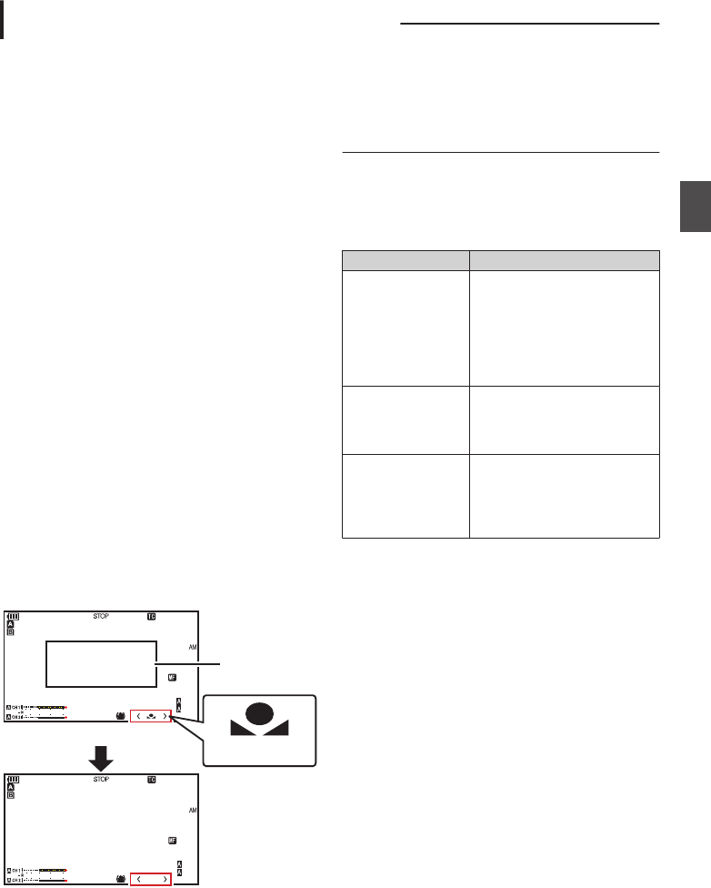
Memory A Mode (A), Memory B Mode
(B)
0Set to the white balance saved in Memory A or
Memory B.
0When the [WHT BAL B/A/PRESET] selection
switch is set to “A” or “B”, press the [y] button
to execute white balance. The white balance will
be automatically adjusted and the adjusted
value will be saved in Memory A or Memory B.
1Prepare the camera recorder.
ASet the [POWER ON/OFF] switch to “ON”.
BSet the [FULL AUTO ON/OFF] switch to “OFF” to
turn off the Full Auto mode.
CSet the [SCENE SELECT] switch to “OFF” to turn
off the Scene Select mode.
DPress the [IRIS] button to set to the Auto mode.
2Set the [WHT BAL B/A/PRESET] selection
switch to “A” or “B”.
3Locate a place with similar lighting conditions
as the object to be shot, place a white object
near the center of the screen and zoom in to
fill the screen with white.
4Press the [
y
] (Auto White Balance) button.
0The white detection frame appears when Auto
White Balance is activated. Fill the frame with
white completely.
0While Auto White Balance is starting up,
“A<
y
>” or “B<
y
>” appears on the screen.
(
y
mark appears blinking)
0After the correct white balance is obtained, an
estimated value of the current color
temperature is displayed.
.
100min
50min
282min
A 1/100
F1 . 6
0dB
AE+6
5 . 6 f t
12 : 34 : 56
Jan 12, 2016
00: 00: 00.00
1920x1080
60 i HQ
4030 20 10 0
100min
50min
282min
A 1/100
F1 . 6
0dB
AE+6
5 . 6 f t
12 : 34 : 56
Jan 12, 2016
00: 00: 00.00
1920x1080
60 i HQ
4030 20 10 03700K
Result Display
[AWB] Activating
White Detection
Frame
Blinking
Caution :
0Do not use highly reflective objects, such as
metals. Doing so may result in improper white
balance adjustment.
0The Auto White Balance function cannot provide
optimum white balance with an object outside the
adjustment range, for example when it contains
only a single color or not enough white color.
Error Message
If the Auto White Balance adjustment is not
correctly completed, one of the following
messages will appear for about 3 seconds.
Message Status
Auto White * NG:
Object
(*A or B)
Displayed when there is not
enough white color on the
object, or when the color
temperature is not suitable.
Use another white object and
adjust the white balance
again.
Auto White * Error:
Low Light
(*A or B)
Displayed when the lighting is
dark. Increase the lighting
and adjust the white balance
again.
Auto White * Error:
Over Light
(*A or B)
Excessive illumination.
Displayed when the lighting is
too bright. Decrease the
lighting and adjust the white
balance again.
Adjusting the White Balance 55
Shooting

White Paint Adjustment
You can fine-tune the white balance saved in
Memory A or Memory B.
1Select [Main Menu] B [Camera Process] B
[White Balance] B [AWB Paint] and press
the Set button (R).
The White Paint Adjustment screen appears.
.
1
2Adjust the R and B values.
Use the cross-shaped button (JK) to adjust R
value and (HI) to adjust B value.
.
3Press the Set button (R).
Returns to the [White Balance] screen.
.
B Value
R Value
Memo :
0Selecting [y] will usually clear the White Paint
Adjustment value. But when [Main Menu] B
[Camera Process] B [White Balance] B [Clear
Paint After AWB] is set to “Off”, values will not
be cleared even when [y] is selected.
(A P94 [ Clear Paint After AWB ] )
0If [White Balance] has been assigned to the user
button, pressing the assigned user button will
display the AWB Paint Adjustment screen.
(A P34 [Assignment of Functions to User
Buttons] )
Adjusting the Camera
Image
The picture quality of the camera can be set using
the [Camera Process] menu.
As the adjustments are shown on the screen, you
can adjust the values while checking the picture
quality on the camera.
0[Detail]
0[Master Black]
0[Black Toe]
0[White Clip]
0[Gamma]
0[White Balance]
0[Color Matrix]
0[Color Gain]
Memo :
0For details of the respective items, see the
[Camera Process] menu.
(A P92 [Camera Process Menu] )
0During Scene Select mode, use the Scene
Select setting menu to set the picture quality.
56 Adjusting the White Balance
Shooting

Using the Image Stabilizer
Reduces blurring of images due to camera shake.
1Check whether the image stabilizer feature
is turned ON or OFF.
If the image stabilizer icon (i/j) does not
appear on the screen display, the image
stabilizer function is OFF.
.
P13000K 1/100
F1 . 6
0dB
AE+6
ND 1 /64
12 : 34 : 56
Jan 12, 2016
00:00:00.00
4030 20 10 0
5 . 6 f t
2Press the [OIS/2] button to turn ON the
image stabilizer feature (when image
stabilizer feature is OFF).
The image stabilizer feature switches between
ON and OFF with every press of the [OIS/2]
button.
0OFF:
Use this setting when the camera recorder is
secured, such as when using a tripod.
0ON:
Reduces blurring of images due to camera
shake.
Memo :
0Select [Main Menu] B [Camera Function] B
[OIS] B [Level] to set the correction level.
(A P89 [ Level ] )
0Correction by this feature may not be sufficient
when camera shake is too strong.
0“OIS” is assigned to [OIS/2] button in factory
default.
0“OIS” can also be assigned to other user
buttons.
(A P34 [Assignment of Functions to User
Buttons] )
0The angle of view becomes narrower at the wide
angle end when the image stabilizer function is
turned ON (High).
Audio Recording
You can record audio from the two channels (CH1/
CH2) in synchronization with video images on this
camera recorder.
Select from the four options below to record the
audio.
0Built-in Microphone
0Microphone connected to [AUX] terminal
0Microphone connected to [INPUT1] terminal
0Microphone connected to [INPUT2] terminal
.
FULL AUTO
ON
OFF
CH1
INT
INPUT1
INPUT2
AUTO
MANUAL
CH2
INPUT2INPUT1
PEAKINGLCD BRIGHT
CH2CH1
LINE
MIC
MIC
+48V
INPUT2 INPUT1
AUX
POWER
/CHG
Selecting Audio to Be Recorded in Each
Channel
Select the audio to be recorded in CH1/CH2.
- Switch Setting Connected Devices
CH1 INT 0Built-in Microphone
0Microphone connected to
[AUX] terminal
INPUT1 Microphone connected to
[INPUT1] terminal
CH2 INT 0Built-in Microphone
0Microphone connected to
[AUX] terminal
INPUT1 Microphone connected to
[INPUT1] terminal
INPUT2 Microphone connected to
[INPUT2] terminal
Memo :
0When “INT” is set, the built-in microphone is
disabled if a microphone is connected to the
[AUX] terminal; audio from the microphone
connected to the [AUX] is recorded.
0When “INT” is selected, set the reference input
level in [Main Menu] B [A/V Set] B [Audio Set]
B [Int. Mic Gain]/[AUX Gain].
(A P101 [ Int. Mic Gain ] )
(A P101 [ AUX Gain ] )
Using the Image Stabilizer 57
Shooting

Setting Input Channel to [INPUT1]/[INPUT2]
Select the audio to input to [INPUT1] and [INPUT2]
terminals with the [INPUT1]/[INPUT2] mode
switch.
Setting Description
[LINE] Use this setting when connecting to
an audio device or other equipment.
The reference input level is +4 dBu.
[MIC] Use this setting when connecting to
a dynamic microphone.
[MIC+48V] Use this setting when connecting to
a microphone (phantom
microphone) that requires a +48 V
power supply.
Memo :
0When “MIC” or “MIC+48V” is selected, set the
reference input level in [Main Menu] B [A/V
Set] B [Audio Set] B [Input1 Mic Ref.]/[Input2
Mic Ref.].
(A P101 [ Input1 Mic Ref. ] )
(A P101 [ Input2 Mic Ref. ] )
Caution :
0When connecting a device that does not require
a +48 V power supply, make sure that it is not
set to the “MIC+48V” position.
0When the [INPUT1]/[INPUT2] mode switch is
set to “MIC”, make sure that a microphone is
connected to the [INPUT1]/[INPUT2] terminal. If
you increase the recording level when a
microphone is not connected, noise from the
input terminal may be recorded.
0When a microphone is not connected to the
[INPUT1]/[INPUT2] terminal, set the [INPUT1]/
[INPUT2] mode switch to “LINE” or adjust the
volume with the [CH1]/[CH2] recording level
adjustment knob.
Adjusting Audio Recording Level
You can select to adjust the audio recording levels
for the two channels (CH1/CH2) manually or
automatically.
.
FULL AUTO
ON
OFF
CH1
INT
INPUT1
INPUT2
AUTO
MANUAL
CH2
L
C
CH2CH1
Manual Adjustment Mode (Manual
Adjustment)
0Set the [CH1/CH2 AUTO/MANUAL] switch on
the camera recorder to “MANUAL” to enter the
manual adjustment mode, and use the [CH1]/
[CH2] recording level adjustment knob to set the
recording level.
0You can adjust the level manually during the
recording, recording standby, and stop modes.
oWhen the input channel is set to “INPUT1”/
“INPUT2”
1Set the [CH1/CH2 AUTO/MANUAL]
selection switch to “MANUAL” for the
channel to be adjusted manually.
2Turn the corresponding [CH1]/[CH2]
recording level adjustment knob to adjust
the level.
When [Audio Set] B [Limiter] is set to “Off”,
adjust such that the audio level meter does not
light up at -2 dB even for loud sounds.
(A P101 [ Limiter ] )
.
P13000K 1/100
F1 . 6
0dB
AE+6
12 : 34 : 56
Jan 12, 2016
00: 00: 00.00
4030 20 10 0
5 . 6 f t
4030 20 10 0
-2dB
58 Audio Recording
Shooting
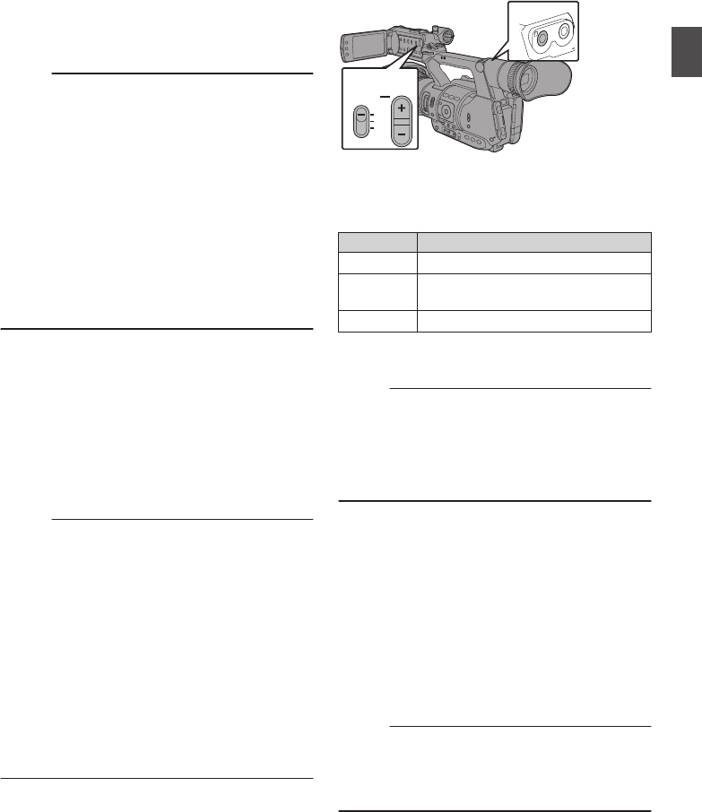
oWhen the input channel is set to “INT” for both
[CH1] and [CH2]
1Set the [CH1 AUTO/MANUAL] selection
switch to “MANUAL”.
2Turn the [CH1] recording level adjustment
knob to adjust the level.
When the built-in microphone and the [AUX]
input terminal are used, the recording levels of
[CH1] and [CH2] are interlocked.
This is also effective when the [CH1 AUTO/
MANUAL] selection switch is set to [CH2].
Memo :
0Select [Limiter], [AGC Response], [AGC Mode],
or [Int. Mic Separation] in the menu to set the
recording audio.
0If [Limiter] is set to other than “Off”, the limiter
operates according to the value set.
(A P101 [ Limiter ] )
0For the reference level to be recorded to an SD
card, set [Main Menu] B [A/V Set] B [Audio
Set] B [Ref. Level] to “-20dB”, “-18dB”, or
“-12dB”. (common for CH1/CH2)
(A P101 [ Ref. Level ] )
0The operations of the [CH2] recording level
adjustment knob and [CH2 AUTO/MANUAL]
selection switch are disabled.
Automatic Adjustment Mode
0
Set the [CH1/CH2 AUTO/MANUAL] selection
switch to “AUTO” or the [FULL AUTO ON/OFF]
switch to “ON” to enter Automatic Adjustment
mode. The audio recording level is set
automatically according to the input level.
0When the [FULL AUTO ON/OFF] switch is set to
“ON”, mode switching with the [CH1/CH2
AUTO/MANUAL] selection switch is disabled.
Memo :
0When [Main Menu] B [A/V Set] B [Audio Set] B
[Limiter] is set to “Off” while in the automatic
adjustment mode, the limiter operates at
-5 dBFS.
0If [Limiter] is set to other than “Off”, the limiter
operates according to the value set.
(A P101 [ Limiter ] )
0When [A/V Set] B [Audio Set] B [Audio On FULL
AUTO] is set to “SW Set”, you can switch the
audio recording mode with the [CH1/CH2
AUTO/MANUAL] selection switch on the
camera recorder even when the [FULL AUTO
ON/OFF] switch is set to “ON”.
(A P103 [ Audio On FULL AUTO ] )
Monitoring Audio Sound
During Recording Using a
Headphone
You can check the recorded audio using
headphone.
.
AUX
MONITOR
CH1
BOTH
CH2
3
1
2
1Connect the headphone.
2Select the channel to monitor with the
[MONITOR] selection switch.
Setting Description
[CH1] Outputs the audio recorded in [CH1].
[BOTH] Outputs the audio recorded in
[CH1/CH2].
[CH2] Outputs the audio recorded in [CH2].
3Use the [MONITOR +/-] button to adjust the
monitor volume.
Memo :
0Audio during recording is not output from the
monitor speaker.
0Warning tone is output when there is an
abnormality in the camera recorder or when the
battery is low.
(A P128 [Warning Tone] )
Selecting Audio Output Method When the
[MONITOR] Selection Switch Is Set to “BOTH”
When a stereo type earphone jack is connected,
perform the following setting to output stereo
sound.
1
Set the [MONITOR] selection switch to
“BOTH”.
2Set [Main Menu] B [A/V Set] B [Audio Set]
B [Monitor] to “Stereo”.
(A P103 [ Monitor ] )
Memo :
0You can set the volume of the warning tone in
[Main Menu] B [A/V Set] B [Audio Set] B [Alarm
Level]. (“Off”/“Low”/“Middle”/“High”)
(A P103 [ Alarm Level ] )
Audio Recording 59
Shooting

Setting Time Code
Generator
Presetting the Time Code
Time code and user’s bit data generated from the
internal time code generator are recorded.
This section describes how to set [TC/UB] B [TC
Preset].
(A P95 [ TC Preset ] )
Memo :
0When [Main Menu] B [System] B [Record Set]
B [Record Format] B [Frame & Bit Rate] is set
to “50p” or “50i”, “Drop” cannot be selected.
(A P105 [ Frame & Bit Rate ] )
0You can configure the setting without accessing
the [TC/UB] menu screen.
(A P62 [Setting Time Code without Opening
the Menu] )
Required Settings Before Preset
1Set [TC/UB] B [TC Generator] to “Rec
Run” or “Free Run”.
(A P95 [ TC Generator ] )
0[Rec Run]:
Preset data in the time code generator
operates in run mode during recording mode.
Set this when recording continuous time
code in connecting frames.
0[Free Run]:
Time code starts to operate in run mode from
the preset time in the time code generator.
2Select the framing mode for the time code
generator (only when the frame rate setting
is “60”).
Set using [Main Menu] B [TC/UB] B [Drop
Frame].
(A P95 [ Drop Frame ] )
0[Drop]:
Sets the run mode of the time code generator
to drop frame mode. Use this setting when
placing emphasis on the recording time.
0[Non Drop]:
Sets the run mode of the time code generator
to non-drop frame mode. Use this setting
when placing emphasis on the number of
frames.
Memo :
Drop frame/non-drop frame mode
0When the frame rate setting of [Main Menu] B
[System] B [Record Set] B [Record Format] B
[Frame & Bit Rate] is set to “60p” or “60i”, the
actual number of frames per second is
approximately 59.94. However, the time code
processing standard is “60p” or “60i” frames. To
make up for the frame number discrepancy, the
drop frame mode (Drop) drops the 00 frame and
01 frame every minute except for minutes that
are multiples of 10. However, in the case of
“60p”, the 00, 01, 02 and 03 frame are dropped.
0The non-drop frame mode (Non Drop) does not
drop frames and ignores the discrepancy with
the actual time.
Setting Time Code
.
OIS / 2 LOLUX / 3
AE LEVEL
MENU/THUMB
CANCEL
MENU/THUMB
CANCEL
Setting Time Code Generator 61
Shooting

1Select [Main Menu] B [TC/UB] B [TC
Preset] and press the Set button (R).
(A P95 [ TC Preset ] )
The [TC Preset] screen appears.
.
1
Memo :
0When [TC/UB] B [TC Generator] is set to
“Regen”, the parameter is displayed as “Regen”
and cannot be selected.
(A P95 [ TC Generator ] )
2Set the time code (hour, minute, second,
frame).
Use the cross-shaped button (HI) to place the
cursor at the item to set, then use the cross-
shaped button (JK) to change the values.
.
During drop frame
During non-drop
frame
Cursor
Memo :
0
Press the [OIS/2] button to reset each digit to “0”.
The cursor moves to the time digit (left).
3Check the values and press the Set button
(R).
0The time code is set and the screen returns
to [TC/UB].
0To cancel the setting, press the [CANCEL]
button.
4Press the [MENU/THUMB] button.
Returns to the normal screen.
Setting Time Code without Opening the
Menu
.
AE LEVEL
MENU/THUMB
CANCEL
MENU/THUMB
CANCEL
FOCUS ASSIST/1 OIS / 2
TIME CODE
Memo :
0Settings cannot be made in the following cases.
0[TC/UB] B [TC Generator] has been set to
“Regen”.
0Menu screen is displayed.
0The camera recorder is not in the Camera
mode.
Setting Time Code
1Set [TC/UB] B [TC Generator] to a value
other than “Regen”.
(A P95 [ TC Generator ] )
2Hold down the [MENU/THUMB] button and
press the [FOCUS ASSIST/1] button.
The [TC Preset] setting screen appears.
.
During drop frame
During non-drop frame
Cursor
3Set the time code (hour, minute, second,
frame).
Use the cross-shaped button (HI) to place the
cursor at the item to set, then use the cross-
shaped button (JK) to change the values.
Memo :
0
Press the [OIS/2] button to reset each digit to “0”.
The cursor moves to the time digit (left).
62 Setting Time Code Generator
Shooting

4Check the values and press the Set button
(R).
0The time code is set and the screen returns
to the normal screen.
0To cancel the setting, press the [CANCEL]
button.
Caution :
0When the camera recorder is switched to Media
mode during editing, editing will be canceled
and the screen will close.
0When editing the time code, operation of the
[FOCUS ASSIST/1] and [OIS/2] buttons that are
set in [Main Menu] B [Camera Function] B [User
Switch Set] is disabled. [OIS/2] functions as the
number reset button.
(A P90 [User Switch Set Item] )
Recording Time Code in Continuation of
the Recorded Time Code on SD Card
This camera recorder is equipped with the time
code reader.
1Set [TC/UB] B [TC Generator] to “Regen”.
0When the camera recorder enters from
recording standby mode to recording mode,
it reads the time code already recorded on
the SD card and records the new time code
in continuation of that value.
0The same data as the user’s bit already
recorded on the SD card is recorded.
Memo :
0When [TC/UB] B [TC Generator] is set to
“Regen”, the framing mode of the time code
follows the setting in [TC/UB] B [Drop Frame]
instead of the clip settings.
(A P95 [ Drop Frame ] )
Setting the User’s Bit
You can add the date, time or an 8-digit
hexadecimal number as the user’s bit to the
recorded image.
.
OIS / 2 LOLUX / 3
AE LEVEL
MENU/THUMB
CANCEL
MENU/THUMB
CANCEL
Selecting a Recording Mode
Recording date/time information to the user’s
bit
1Set [Main Menu] B [TC/UB] B [UB Mode] to
“Date” or “Time”, and press the Set button
(R).
(A P95 [ UB Mode ] )
The date or time information is recorded to the
user’s bit.
Memo :
0When “Date” or “Time” is set, [Preset] appears
as “-” and cannot be set.
0“Time” is displayed in the 24-hour format.
Presetting the User’s Bit
Recording arbitrary information (8-digit
hexadecimal) to the user’s bit
Setting Time Code Generator 63
Shooting
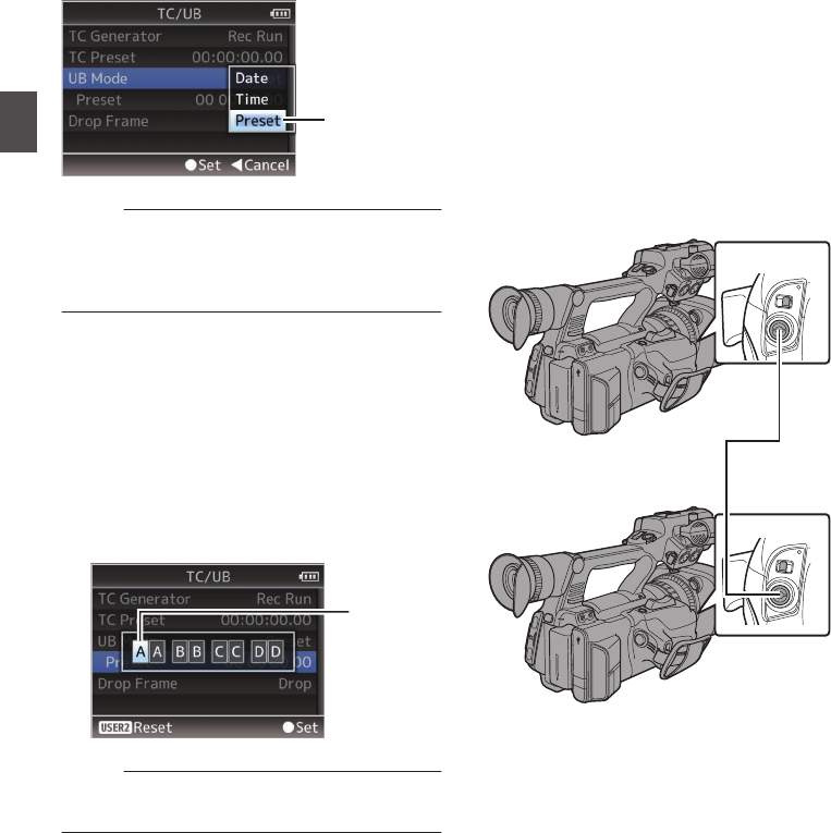
1Set [Main Menu] B [TC/UB] B [UB Mode] to
“Preset”, and press the Set button (R).
(A P95 [ UB Mode ] )
The [UB Mode] setting screen appears.
.
1
Memo :
0When [TC/UB] B [TC Generator] is set to
“Regen”, the parameter is displayed as “Regen”
and cannot be selected.
(A P95 [ TC Generator ] )
2Select [Main Menu] B [TC/UB] B “Preset”
and press the Set button (R).
The [Preset] setting screen appears.
3Use the cross-shaped button (HI) to place
the cursor at the item to set, then use the
cross-shaped button (JK) to change the
values.
Numbers between 0 and 9 or alphabets
between A and F can be specified for the user’s
bit.
.
Cursor
Memo :
0
Press the [OIS/2] button to reset each digit to “0”.
The cursor moves to the left.
4Check the values and press the Set button
(R).
0The user’s bit is set and the screen returns to
[TC/UB].
0To cancel the setting, press the [CANCEL]
button.
5Press the [MENU/THUMB] button.
Returns to the normal screen.
Synchronizing Time Code
on Another Camera
This camera recorder is equipped with a time code
input/output terminal ([TC] terminal).
Connect another camera recorder to the [TC]
terminal and synchronize to the time code.
1Connect the [TC] terminal of the master
device with the [TC] terminal of the slave
device.
Set the [TC IN/OUT] switch of the master device
to “OUT”, and the [TC IN/OUT] switch of the
slave device to “IN”.
.
AUX
INPUT2 INPUT1
DEVICE
AV
A
BATT.RELEASE
POWER
/CHG
B
HDMI
REMOTE
DC
REC
AUX
INPUT2 INPUT1
DEVICE
AV
A
BATT.RELEASE
POWER
/CHG
B
HDMI
REMOTE
DC
REC
IN OUT
TC
IN OUT
TC
[IN]
Slave Device (This Camera Recorder)
[OUT]
Master Device
64 Setting the User’s Bit
Shooting

Settings and Operation of the Camera
Recorder
1Set to Camera mode.
(A P14 [Operation Modes] )
2Set [TC/UB] B [TC Generator] as follows.
0Slave device:
Select “Free Run(Ext)”.
0Master device:
Select “Free Run”.
3Set LCD monitor or viewfinder to Display 1
screen.
4Set the master device and run the time
code.
0When the built-in time code generator is
synchronized with the external time code
data input, the Z icon on Display 1 screen
lights up.
0When time code is not synchronized or time
code input is not available, the Z icon goes
out.
.
P13000K 1/100
F1. 6
0dB
AE+6
12 : 34 : 56
Jan 24 , 2012
00:00: 00.00
4030 20 10 0
5 . 6 f t
Memo :
0The built-in time code generator will continue
operation even when the master device is
disconnected after synchronization.
0User’s bit will become data in the master device.
0While the [TC] terminal is connected, the time
code may be out of synchronization when the
[A/V Set] B [Video Set] B [HDMI out] setting of
the Master device and Slave device is being
changed.
(A P100 [ HDMI out ] )
Setting Zebra Pattern
When the luminance level range for displaying
zebra patterns is specified, diagonal lines (zebra
pattern) are displayed at areas with the specified
luminance levels during shooting.
.
FIX VAR OFF
AE LEVEL
LOCK
IRIS
∞
TIME CODE
ZEBRA/5
1Set the zebra display pattern.
Select the display pattern in [LCD/VF] B
[Shooting Assist] B [Zebra].
2Specify the brightness (luminance) level
range for displaying zebra pattern.
Specify the upper and lower limits of the
luminance level in [LCD/VF] B [Shooting
Assist] B [Zebra] B [Top] and [Bottom].
Item Settings Options
Top Upper luminance
limit for displaying
[Zebra]
5% - 95% (in 5 %
increments), 98%,
100%, Over
Bottom Lower luminance
limit for displaying
[Zebra]
0% - 95% (in 5 %
increments), 98%,
100%
3Display the zebra pattern.
Press the [ZEBRA/5] button to display the zebra
pattern in the specified range.
.
During zebra pattern display, (zebra icon)
is displayed on the display screen in Camera
mode.
Memo :
0“Zebra” is assigned to [ZEBRA/5] button in
factory default.
0“Zebra” can also be assigned to other user
buttons.
(A P34 [Assignment of Functions to User
Buttons] )
Synchronizing Time Code on Another Camera 65
Shooting

Viewing Recorded Videos
Immediately (Clip Review)
You can check (review) the last recorded video clip
on the screen.
However, the video clip cannot be played back if
the settings of the camera recorder are different
from the video format (Resolution/Frame & Bit
Rate/SD Aspect) of the clip.
(A P105 [ Resolution ] )
(A P105 [ Frame & Bit Rate ] )
(A P105 [ SD Aspect ] )
Memo :
0To use this function, assign “Clip Review” to any
of the user buttons. “Clip Review” is assigned to
[C.REVIEW/7] button in factory default.
0“Clip Review” can also be assigned to other user
buttons.
(A P34 [Assignment of Functions to User
Buttons] )
.
AUX
INPUT2 INPUT1
DEVICE
AV
A
BATT.RELEASE
POWER
/CHG
B
HDMI
REMOTE
DC
REC
C.REVIEW/7
1Press the button assigned with the “Clip
Review” function during standby (“STBY”
is displayed).
Playback of the configured section starts.
Memo :
0The video clip is played back according to the
setting in [Main Menu] B [Camera Function] B
[User Switch Set] B [Clip Review]. By default
setting (Last 5sec), the last 5 seconds of the clip
is played back.
(A P90 [ Clip Review ] )
0When playback is complete, the camera
recorder exits Clip Review and returns to
“STBY” (recording standby) mode.
Caution :
0During Clip Review, only the [CANCEL] and
[REC] buttons are enabled.
Press the [CANCEL] button to cancel clip review
and return to “STBY” (recording standby) mode.
Press the [REC] button to cancel clip review and
enter recording mode. It will take some time to
start recording after the button is pressed.
0When the last clip is less than 5 seconds, the
whole clip is played back.
0Only video clips in the currently selected slot can
be reviewed.
0When there are no clips in the selected slot, Clip
Review function is disabled.
0Clip Review is unavailable when Clip
Continuous Rec is paused (“STBYC”, yellow
text). To operate Clip Review, use the
[CANCEL] button to set to “STBYC” (white text)
first.
(A P72 [Clip Continuous Rec] )
0Clip Review is unavailable when the camera
recorder is connected to an external equipment
and the equipment is in recording state.
0Clip Review does not function while the record
trigger is in the REC state.
66 Viewing Recorded Videos Immediately (Clip Review)
Shooting

Dual Rec
0If both the slots are loaded with recordable cards
in the Dual Rec mode ([Slot Mode] is set to
“Dual”), pressing the [REC] button starts
recording simultaneously to the media in both
the slots.
0The clips recorded to the media in both the slots
are identical, and two clips of the same content
can be created only on this camera recorder.
(A P106 [ Slot Mode ] )
.
AUX
INPUT2 INPUT1
DEVICE
AV
A
BATT.RELEASE
POWER
/CHG
B
HDMI
REMOTE
DC
REC
REC
REC
HOLD
REC
A
B
Setting to Dual Rec Mode
1Set [Main Menu] B [System] B [Record
Set] B [Slot Mode] to “Dual”.
(A P106 [ Slot Mode ] )
“DUAL” appears on the display screen.
.
P13000K 1/100
F1. 6
0dB
AE+6
12 : 34 : 56
Jan 12, 2016
00:00: 00.00
4030 20 10 0
5 . 6 f t
DUAL
2Start recording.
0Insert recordable media in both slots, and
press the [REC] button.
0In the Dual Rec mode, recording to the media
in both slots starts at the same time.
0Both the card slot marks turn red, and the
status indicators of both the card slots also
light up in red.
.
P13000K 1/100
F1. 6
0dB
AE+6
12 : 34 : 56
Jan 1 2,2016
00:00: 00.00
4030 20 10 0
5 . 6 f t
100min
50min
REC
Lit in red
3Stop recording.
0Press the [REC] button again.
0Recording to both slots stops, and both the
card slot marks turn white.
0The same clips are recorded to both cards.
.
P13000K 1/100
F1. 6
0dB
AE+6
12 : 34 : 56
Jan 1 2,2016
00:00: 00.00
4030 20 10 0
5 . 6 f t
100min
50min
White
Memo :
0During recording in the Dual Rec mode, both the
card slot marks light up in red.
0During recording in the Dual Rec mode to two
cards with a different amount of remaining
space, if the space of one card runs out,
recording to both slots will stop automatically.
After recording stops, recording automatically
resumes for the card with remaining space.
Although the clips are separated in this case, the
clips can be seamlessly joined by arranging
them on the timeline of the editing software since
they are recorded seamlessly.
0
If the last clip on the cards that are inserted in the
two slots are different from each other, and the
time code operating mode is set to “Regen”, the
Regen mode for the selected card slot will be
enabled in the next recording.
68 Dual Rec
Shooting

Caution :
0To perform recording in the Dual Rec mode, it is
recommended that you start recording by
making use of two cards with the same capacity
and from the formatted state.
0You can combine the use of the Dual Rec mode
with a special recording mode. While in the Dual
Rec mode, you can also set [Rec Mode] to
“Normal”, “Pre Rec”, “Interval Rec”, or “Frame
Rec”.
(A P71 [Special Recording] )
0When both slots are inserted with recordable
cards, the Dual Rec (simultaneous recording)
operation can be performed. If a recordable
media is only inserted in one of the slots, you can
also start recording with one card.
0In the Dual Rec mode, continuous recording by
switching from one slot to another cannot be
performed. Continuous recording will not be
performed if a recordable media is inserted in a
slot after recording to the other slot has started.
0When recording to one slot is in progress with
the recorder set to the Dual Rec mode, inserting
a recordable media to the other slot does not
enable the Dual Rec operation. To perform the
Dual Rec operation, stop recording temporarily
(excluding pausing recording in the Clip
Continuous Rec mode), and start again.
0When one of the cards is accidentally removed
while recording is in progress in the Dual Rec
mode, recording to the card in the other slot will
continue. However, repair of the accidentally
removed card by the recovery function may fail.
0If an error occurs on one of the cards while
recording is in progress in the Dual Rec mode,
recording of the erroneous card stops, while that
of the other card continues.
0Operations on clips recorded in the Dual Rec
mode, such as clip deletion in the Media mode
or appending of OK marks, can only be
performed on the card in the selected slot.
Backup Rec
0The Backup Rec mode allows you to make use
of the media in slot B for backup recording by
controlling the starting and stopping of recording
in slot B without using the [REC] button.
0Start or stop the recording using [Main Menu] B
[System] B [Record Set] B [Slot Mode] B
[Backup Rec] or press the user button that is
assigned with “Backup Trig”.
(A P106 [ Slot Mode ] )
(A P90 [User Switch Set Item] )
.
Slot B
Slot A
Clip 3
Clip 2
Clip 1
Clip 2
Slot B stops
recording
Slot A stops
recording
Slot A starts
recording
Slot B starts
recording
Memo :
0During the Backup Rec mode (when [Slot
Mode] is set to “Backup”), you can control
recording to the 2 slots at different timings, and
backup recording can only be performed on this
camera recorder.
(A P106 [ Slot Mode ] )
0You can record without worrying about missing
the important scenes by setting slot B to be
always recording (backup recording) and using
the [REC] button to start/stop recording of only
the required scenes in slot A.
0It is recommended to use a media with high
capacity in slot B.
Dual Rec 69
Shooting

1Set [Main Menu] B [System] B [Record
Set] B [Slot Mode] to “Backup”.
(A P106 [ Slot Mode ] )
“BACKUP” appears on the display screen.
.
P13000K 1/100
F1. 6
0dB
AE+6
12 : 34 : 56
Jan 12, 2016
00:00: 00.00
5 . 6 f t
4030 20 10 0
BACKUP
2Start backup recording. (Backup recording
into slot B)
0Select “REC” in [Main Menu] B [System] B
[Record Set] B [Slot Mode] B [Backup Rec]
and press the Set button (R).
(A P106 [ Slot Mode ] )
0You can also press the user button that is
assigned with “Backup Trig”.
(A P90 [User Switch Set Item] )
0Backup recording into slot B starts. (The
characters “BACKUP” appear in red.)
0The card slot mark of slot B turns red
(selected state), and the status indicator of
slot B also blinks in red.
.
P13000K 1/100
F1. 6
0dB
AE+6
12 : 34 : 56
Jan 12, 2016
00:00: 00.00
4030 20 10 0
5 . 6 f t
100min
50min
100min
50min
Red (selected)
Red
3Start normal recording (normal recording
into slot A)
0Press any of the [REC] buttons.
0Recording into the media in slot A starts.
(The characters “RREC” appear in red.)
0The card icon of slot A turns red (unselected
state), and the status indicator of slot A blinks
in red.
.
P13000K 1/100
F1. 6
0dB
AE+6
12 : 34 : 56
Jan 12, 2016
00:00: 00.00
4030 20 10 0
5 . 6 f t
100min
50min
100min
50min
Red (not selected)
4Stop normal recording.
0Press any of the [REC] buttons again.
0Recording to slot A stops, and the card slot
mark of slot A turns white (unselected state).
0The characters “RREC” (red) changes back
to “STBY” (white).
0The status indicator of slot A goes out.
.
P13000K 1/100
F1. 6
0dB
AE+6
12 : 34 : 56
Jan 12, 2016
00:00: 00.00
4030 20 10 0
5 . 6 f t
100min
50min
100min
50min
White (not selected)
70 Backup Rec
Shooting

5Stop backup recording.
0Select [STBY] in [Main Menu] B [System] B
[Record Set] B [Slot Mode] B [Backup Rec]
and press the Set button (R).
(A P106 [ Slot Mode ] )
0You can also press the user button that is
assigned with “Backup Trig”.
(A P90 [User Switch Set Item] )
0Recording to slot B stops, and the card slot
mark of slot B turns white (unselected state).
0The characters “BACKUP” changes back to
white.
0The status indicator of slot B lights up in
green.
.
P13000K 1/100
F1. 6
0dB
AE+6
12 : 34 : 56
Jan 12, 2016
00:00: 00.00
4030 20 10 0
5 . 6 f t
100min
50min
100min
50min
White
Memo :
0During backup recording, if the space of one
card runs out, recording stops only for the card
that is full.
0When recording to both slots is stopped,
recording in the Regen mode will be enabled for
the card slot in which recording started.
0When recording is started in the other slot while
recording to one slot, the clip being recorded is
split and simultaneous recording to the other
card starts.
0When recording is stopped for either slot A or B
while recording to both slots, the clip on the slot
which is still recording is split.
0Although the clips are separated during
recording the clips can be seamlessly joined by
arranging them on the timeline of the editing
software since they are recorded seamlessly.
0Clip Cutter Trig cannot be performed during
backup recording.
(A P67 [Splitting the Clips Freely (Clip Cutter
Trig)] )
0When [Slot Mode] is set to “Backup”, [Rec
Mode] can only be set to “Normal”.
(A P106 [ Rec Mode ] )
Special Recording
Besides the normal recording mode, four special
recording methods are available in this camera
recorder. They are Pre Rec, Clip Continuous,
Frame Rec and Interval Rec.
Memo :
0Set using [Main Menu] B [System] B [Record
Set] B [Rec Mode].
(A P106 [ Rec Mode ] )
Pre Rec
0By setting the number of seconds in the [Pre Rec
Time], you can start recording video and audio
before actual recording starts based on the [Pre
Rec Time] setting.
0When starting actual recording while the camera
recorder is in Recording Standby (STBYP)
mode, you can start recording a few seconds
earlier based on the [Pre Rec Time] setting.
0Using Pre Rec allows you to record a complete
event without missing the initial scenes even if
you start the recording late.
Memo :
0Pre Rec Time can be set to “5sec”, “10sec”, or
“15sec” in [Main Menu] B [System] B [Record
Set] B [Rec Mode] B [Pre Rec Time].
0When the frame rate setting in [Main Menu] B
[System] B [Record Set] B [Record Format] B
[Frame & Bit Rate] is set to “XHQ”, “15sec”
cannot be selected.
(A P106 [ Pre Rec Time ] )
.
(Recording stops)
Press [REC]
(Recording starts)
Press [REC]
Recording starts a
number of seconds
earlier based on the
[Pre Rec Time] setting
(Recorded video and audio)
Completed Clip
Backup Rec 71
Shooting

1Set [Rec Mode] to “Pre Rec”.
(A P106 [ Rec Mode ] )
0Set [Main Menu] B [System] B [Record
Set] B [Rec Mode] to “Pre Rec”.
0The display changes (“STBY” B “STBYP”).
2Press the [REC] button to start recording in
Pre Rec mode.
0The display changes (“STBYP” B
“RRECP”) and the card slot status indicator
lights up in red.
0Press the [REC] button again to pause
recording. The display changes (“RRECP”
B “STBYP”) and the card slot status
indicator lights up in green.
Caution :
0When the interval between start and stop
recording is short, “STBYP” may not be
displayed immediately after recording is
complete.
“RRECP” B “STBYP” (“STBY” blinks in red) B
“STBYP” is displayed.
0When the SD card becomes full during
recording, recording stops and “STOP” is
displayed.
0Video and audio before the above mentioned
time may not be recorded after recording starts
in the following cases.
0Immediately after power on
0Immediately after recording stops
0Immediately after switching from Media
mode to Camera mode
0Immediately after setting [Rec Mode]
0Immediately after the end of Clip Review
0Immediately after changing file format
0Immediately after changing video format
Clip Continuous Rec
0In normal recording, when the recording stops,
the image, audio, and accompanying data from
the start till the end of the recording are recorded
as one “clip” on the SD card.
0This mode allows you to consolidate several
rounds of “startstop recording” into one clip.
Example:
In normal recording, three clips are generated as
Recording 1, Recording 2, and Recording 3.
However, recording in this mode generates only
one clip.
.
(Recorded video and audio)
Completed Clip
Recording 3
Recording 2
Recording 1
Recording 3
Recording 2
Recording 1
(Recording stops)
Press and hold [REC]
(Recording pauses)
Press [REC]
(Recording pauses)
Press [REC]
(Recording resumes)
Press [REC]
(Recording resumes)
Press [REC]
(Recording starts)
Press [REC]
1Set “Rec Mode” to “Clip Continuous”.
(A P106 [ Rec Mode ] )
0Set [Main Menu] B [System] B [Record
Set] B [Rec Mode] to “Clip Continuous”.
0The display changes (“STBY” B “STBYC”).
2Start recording. (Recording 1)
0Press the [REC] button to start recording in
Clip Continuous mode.
0The display changes (“STBYC” B
“RRECC”) and the card slot status indicator
lights up in red.
3Pause recording.
0Press the [REC] button again to pause
recording. The display changes (“RRECC”
B “STBYC” (yellow text)).
0The card slot status indicator remains lighted
in red.
Memo :
0When the [CANCEL] button is pressed while the
camera recorder is paused (STBYC), the
display changes (“STBYC” (yellow text) B
“STBYC” (blinking yellow text) B “STBYC”
(white text)), and a “clip” is generated. The card
slot status indicator lights up in green.
4Resume recording. (Recording 2)
0Press the [REC] button again to resume
recording. The display changes (“STBYC”
(yellow text) B “RRECC”).
0The card slot status indicator remains lighted
in red.
72 Special Recording
Shooting

5Pause recording.
0Press the [REC] button again to pause
recording. The display changes (“RRECC”
B “STBYC” (yellow text)).
0The card slot status indicator remains lighted
in red.
6Resume recording. (Recording 3)
0Press the [REC] button again to resume
recording. The display changes (“STBYC”
(yellow text) B “RRECC”).
0The card slot status indicator remains lighted
in red.
7Press and hold the [REC] button.
0Recording stops and the display changes
(“RRECC” B “STBYC”). A “clip” is
generated.
0The card slot status indicator lights up in
green.
8Press the [REC] button again.
0The display changes (“STBYC” B
“RRECC”) and the card slot status indicator
lights up in red.
0A new “clip” is generated from here.
Memo :
0The following operations cannot be performed
while recording is paused (STBYC, yellow text).
0Clip Review operation
(A P66 [Viewing Recorded Videos
Immediately (Clip Review)] )
0Switching SD card slots
0Switching operation mode
(A P14 [Operation Modes] )
Caution :
0Do not remove the SD card during recording
(RRECC, red text) or recording pause
(STBYC, yellow text).
0To remove the SD card in the “Clip
Continuous” mode, press the [CANCEL] button,
check that “STBYC” (white text) is displayed
and the card slot status indicator lights up in
green before you remove the card.
0When the SD card becomes full during
recording, recording stops and “STOP” is
displayed.
0When the [POWER ON/OFF] switch is turned off
during recording or recording pause, recording
stops and power is cut off after a clip is
generated.
Caution :
0If the power is cut off due to low battery power,
a proper clip may not be generated.
Frame Rec
In normal recording, when the recording stops, the
image and accompanying data from the start till the
end of the recording are recorded as one “clip” on
the SD card.
In this mode, recording starts with every press of
the [REC] button, and only the specified number of
frames is recorded.
The recording can be written to the media as a
single clip until it is stopped.
Memo :
0Audio will not be recorded.
0Until a specified amount of recordings is
accumulated, the file cannot be written to the
media.
0If the specified amount is not reached when
recording is stopped, normal recording is
performed and frames are added to the ending
of the clip until the amount is reached. (Padding)
0After the specified number of frames is recorded
and written to the media, recording will be
performed until the same number is
accumulated again.
.
Specific amount of data
Actual clips recorded to the media
Records number of frames specified in [Rec Frames]
(Padding data)
Normal recording
PausePausePause
Recording resumes
Recording resumes
Press [REC]Press [REC]
(Frame Rec stops)(Frame Rec starts)
Press and hold [REC]Press [REC]
Special Recording 73
Shooting

Playing Recorded Clips
To play back clips recorded on SD cards, switch to
the Media mode.
Press and hold the [MODE] selection button in
Camera mode to enter Media mode. A thumbnail
screen of the clips recorded on the SD card is
displayed.
You can play back the selected clip on the
thumbnail screen.
Memo :
0When an SD card without any clips is inserted,
“No Clips” is displayed.
Operation Buttons
Use the operation buttons, on the side control
panel of the camera recorder or the LCD monitor,
to operate the thumbnail screen.
.
AE LEVEL
MENU/THUMB
CANCEL
MENU/THUMB
CANCEL
FOCUS ASSIST/1 OIS / 2 LOLUX / 3
TIME CODE
DISPLAY STATUS
A
D
B
C
A
B
C
D
E F G
I H
A[MENU/THUMB] Button
0Displays the menu.
0Press this button to close the menu screen
during menu display and return to the
thumbnail screen.
B[CANCEL] (Stop) Button
Cancels settings and returns to the previous
screen.
CSet (Play) Button
0Sets the values and items. (Confirm)
0Plays back the selected clip.
DCross-Shaped Button (JKHI)
Moves the cursor.
E[FOCUS ASSIST/1] Button
0Switches the OK mark of the clip selected by
the cursor.
0If an OK mark has been appended, it will be
deleted. Otherwise, an OK mark will be
appended.
F[OIS/2] Button
0Switches the selection status of the clip
selected by the cursor.
0Clips being selected are displayed with
check mark.
G[LOLUX/3] Button
Enters the action selection screen.
H[DISPLAY] Button
Switches between the “Standard Screen” and
“Detailed Screen”.
I[STATUS] Button
Displays the media information screen.
Thumbnail Screen
0“Standard Screen” and “Detailed Screen” are
available.
Use the [DISPLAY] button to switch between the
screens.
0Thumbnails are displayed in order of recording
from the oldest to most recent.
Standard screen
.
00000357 2016-01-02 02:40:41
AJ
H
C
B
G
E
D
F
I
K
ASD Card Information
0Displays the status of the inserted SD card,
selected SD card, write-protect switch, and
the need for restoring.
0Use the [SLOT A/B] switch to switch slots.
Clips in slot A and B cannot be displayed at
the same time.
W z:Write-protect switch of the SD card
in slot A is set.
S:SD card in slot B needs to be
restored or formatted, or is an
unsupported SD card.
BClip Mark
Displays the clip information (properties).
.
A
BD
E
C
AOK Mark
Clip is appended with OK mark.
76 Playing Recorded Clips
Playback

Memo :
0Clips appended with OK marks cannot be
deleted on the camera recorder.
0When [Main Menu] B [System] B [Record
Set] B [Record Format] B [Format] is set to
“AVCHD”, the OK mark indicates that the clip is
protected.
(A P105 [ Format ] )
BContinued From Mark
This mark indicates that the current clip is
continued from another SD card when
recording is divided and made on several SD
cards.
CUneditable Mark
0This mark indicates that an OK mark cannot
be appended to or deleted from the clip, and
the clip cannot be deleted.
0When [Main Menu] B [System] B [Record
Set] B [Record Format] B [Format] is set to
“AVCHD”, clips that are not recorded on this
camera recorder cannot be edited.
DContinue Mark
This mark indicates that recording of the current
clip is continued to another SD card when
recording is divided and made on several SD
cards.
ECheck Mark
0A green check mark is displayed when the
clip is selected.
0Magenta and gray check marks are
displayed in multiple selection mode.
(A P82 [Selecting and Performing
Operations on Multiple Clips] )
CCursor
Clip to be worked on. Use the cross-shaped
button (JKHI) to move the cursor.
DThumbnail Substitution Display
.
A B
AA clip with corrupted management information.
It cannot be played back even if you press the
Set (Play) button.
BA clip that cannot be played back nor displayed
in thumbnail with the current video format
settings.
It cannot be played back even if you press the
Set (Play) button.
Memo :
0Depends on the [Main Menu] B [System] B
[Record Set] B [Record Format] B [System],
[Resolution] and [Frame & Bit Rate] settings.
(A P105 [ System ] )
(A P105 [ Frame & Bit Rate ] )
0When [Record Format] B [Format] is set to
“AVCHD”, you may not be able to play back files
recorded on a camera recorder other than the
JY-HM360 series.
If a file cannot be played back, the above
thumbnail substitution display 2 is displayed.
EClip Name
The file name (clip number) of the selected clip
is displayed.
FOperation Guide
0Displays a guide for the current operation
buttons.
0The action selection screen is displayed
when the User 3 ([LOLUX/3]) button is
pressed.
(A P78 [Actions] )
GRecording Start Time
Displays the recording start time of the clip.
Memo :
0The date/time display is dependent on the [LCD/
VF] B [Display Settings] B [Date Style]/[Time
Style] settings in the [Main Menu] screen.
(A P99 [ Date Style ] )
(A P99 [ Time Style ] )
HScroll Bar
0Indicates the scroll position.
0Black space below the scroll bar (white)
indicates that there are more pages.
0When the scroll bar (white) is at the bottom,
this indicates the last page.
IRemaining Battery Power
(A P26 [Power Status Display] )
JNumber of Clips
0If none of the clips are selected, the “running
number/total number of clips” of the clip to be
displayed appears.
0Even if only one clip is selected, the number
of selected clips in the current slot is
displayed.
Playing Recorded Clips 77
Playback

Detailed screen
* Items that are common with the Standard screen
will not be described. Refer to “[Standard
screen] (A P 76)”.
.
Jan 1, 2016 00:00:19
C
B
A
AThumbnail
Thumbnail of the clip selected by the cursor.
Use the cross-shaped button (HI) to move the
cursor.
BScroll Mark (DE)
0If there are previous clips, D appears on the
left.
0If there are more clips, E appears on the right.
0The marks will not be displayed if there are
no clips before and after the current clip.
CMetadata
Metadata of the clip pointed by the cursor.
You can use the cross-shaped button (JK) to
scroll.
Actions
The action selection screen is displayed when the
User 3 ([LOLUX/3]) button is pressed.
You can perform the following operations.
Item Description
Select All Clips Selects all clips.
Select OK
Marked
Selects all clips appended with
OK mark.
Select Range Specifies the range when
selecting multiple clips.
(A P82 [Selecting Multiple
Clips Randomly] )
Deselect All Clears all clip selections.
Item Description
Add OK Mark Appends an OK mark.
0This Clip:
Appends an OK mark to the
clip pointed by the cursor.
0Selected Clips:
Appends an OK mark to the
clips selected (appended
with check mark).
0All Clips:
Appends an OK mark to all
clips.
Delete OK Mark Deletes the OK mark.
0This Clip:
Deletes the OK mark of the
clip pointed by the cursor.
0Selected Clips:
Deletes the OK mark of the
clips selected (appended
with check mark).
0All Clips:
Deletes the OK mark of all
clips.
Delete Clips Deletes clip. However, clips with
OK mark cannot be deleted.
0This Clip:
Deletes the clip pointed by
the cursor.
0Selected Clips:
Deletes the clips selected
(appended with check
mark).
0All Clips:
Deletes all clips.
Trim This Clip Trims the clip pointed by the
cursor.
78 Playing Recorded Clips
Playback
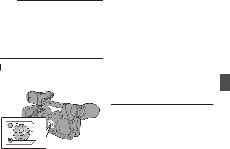
Memo :
0The object of action is the clip of the current slot
being displayed.
0[Selected Clips] cannot be performed if there are
no selected (appended with check mark) clips.
0[This Clip] cannot be performed if there are more
than one selected (appended with check mark)
clips.
0If the write-protect switch of an SD card is set,
OK mark cannot be appended or deleted, and
the clips cannot be deleted.
Playing back
Use the operation buttons on the side control panel
of the camera recorder to play back.
.
AE LEVEL
MENU/THUMB
CANCEL
A
C
B
AIW Button
0Plays back/pauses the clip pointed by the
cursor.
0You can press the cross-shaped button (HI)
to perform frame-by-frame forward playback
during pause mode.
BS/T Button
Skips in the reverse or forward direction.
O/N Button
During Playback:
Fast forwards in the reverse or forward
direction.
While paused:
Frame-by-frame playback in the reverse or
forward direction.
Co Button
Stops playback.
1In the thumbnail screen, move the cursor to
the clip to be played back.
Move the cursor to the clip to be played back
using the cross-shaped button (JKH I).
2Press the playback/pause button.
Playback of the selected clip starts.
Audio Output during Playback
0You can confirm the playback sound from the
monitor speaker, or the headphone connected
to the [x] terminal. When a headphone is
connected to the [x] terminal, sound cannot be
output from the monitor speaker.
(A P126 [Connecting the Headphone] )
0Adjust the volume of the monitor speaker and
headphone using the [MONITOR +/-] volume
adjustment button on the LCD monitor section
of the camera recorder.
Time Code Playback
Time code or user’s bit recorded on an SD card can
be displayed on the LCD monitor and viewfinder.
Memo :
0If a section without time code is played back, the
time code will stop. However, playback will
continue.
Playing Recorded Clips 79
Playback
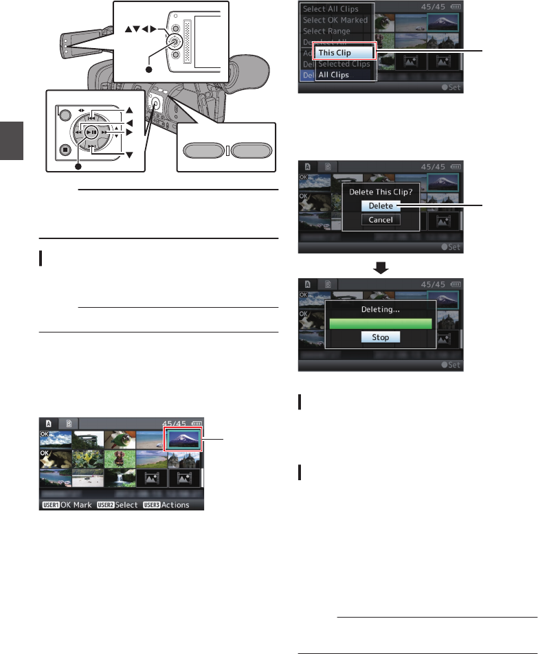
Deleting Clips
Delete clip.
.
OIS / 2 LOLUX / 3
AE LEVEL
MENU/THUMB
CANCEL
MENU/THUMB
CANCEL
Memo :
0Clips appended with OK marks cannot be
deleted on the camera recorder.
0Read-only clips can be deleted on a PC.
Deleting One Clip
Delete the clip (one clip) pointed by the cursor in
[Delete Clips] B [This Clip] in the menu.
Memo :
0Clips with OK mark cannot be deleted.
During Thumbnail Screen
1Move the cursor to the clip to be deleted.
Move the cursor to the clip to be deleted using
the cross-shaped button (JKH I).
.
1
2Press the [LOLUX/3] button.
The action selection screen is displayed.
3Select [Delete Clips] B [This Clip] and press
the Set button (R).
A screen to confirm deletion appears.
.
3
4Select [Delete] using the cross-shaped
button (JK), and press the Set button (R).
Deleting starts.
.
4
Selecting and Deleting Multiple Clips
To select and delete multiple clips, refer to
“[Selecting and Performing Operations on Multiple
Clips] (A P 82)”.
Deleting All Clips
Delete all clips that are displayed.
1Press the [LOLUX/3] button.
The action selection screen is displayed.
2Select [Delete Clips] B [All Clips].
A screen to confirm deletion appears.
3Select [Delete] and press the Set button
(R).
Deleting starts.
Memo :
0The time taken to delete clips depends on the
number of clips to be deleted.
80 Deleting Clips
Playback

Appending/Deleting OK
Mark
0You can append OK marks to the clips for
important scenes.
0Clips appended with OK marks cannot be
deleted, thus protecting the important clips.
0When the camera recorder is in Media mode,
you can delete the OK marks appended during
recording, or append/delete OK marks after
shooting.
.
AE LEVEL
MENU/THUMB
CANCEL
MENU/THUMB
CANCEL
LOLUX / 3FOCUS ASSIST/1
During Thumbnail Screen
1Press the [FOCUS ASSIST/1] button.
0If the clip does not have an OK mark, an OK
mark will be appended.
0If the clip is appended with an OK mark, the
OK mark will be deleted.
.
OK Mark
During Playback or Pause Screen
1Press [FOCUS ASSIST/1] button during clip
playback.
0If the clip does not have an OK mark, an OK
mark will be appended.
0If the clip is appended with an OK mark, the
OK mark will be deleted.
.
1000/2000
12:34:56
12:34:56
Jan 12,2016
Jan 12,2016
00:00:00.00
00:00:00.00
40
40
30
30
20
20
10
10 0
282min
282min
1920x1080
1920x1080
60i HQ
60i HQ
1000/2000
1000/2000
OK Mark
Memo :
0The clip pauses when an OK mark is appended
or deleted during playback.
Appending/Deleting OK Mark of
Multiple Clips
To select and append/delete OK mark for multiple
clips, refer to “[Selecting and Performing
Operations on Multiple Clips] (A P 82)”.
Appending/Deleting OK Mark 81
Playback

Selecting and Performing
Operations on Multiple
Clips
0Multiple clips can be selected during thumbnail
screen or playback screen display.
0After selecting multiple clips, perform
appending/deleting of OK mark, deleting of clips
using the action selection screen.
0After selecting multiple clips, the selections will
be canceled by the following operations.
0When [Deselect All] in the action menu is
selected
0When exiting Media mode from the thumbnail
screen
0When removing the SD card
0When switching the slot in use
Selecting Multiple Clips Randomly
1Move the cursor to a clip without check
mark, and press the [OIS/2] button.
A green check mark appears on the clip.
.
1
2Repeat Step 1 to select multiple clips.
0Multiple clips can be selected.
0Press the [LOLUX/3] button while the
multiple clips are selected.
0Appends OK mark together:
[Add OK Mark] B [Selected Clips]
0Deletes OK mark together:
[Delete OK Mark] B [Selected Clips]
0Deletes selected clips together:
[Delete Clips] B [Selected Clips]
Memo :
0Selecting clips appended with check mark and
pressing the [OIS/2] button will cancel the
selection.
0If the operation is performed on multiple clips at
the same time, a progress bar appears. You can
stop the operation by pressing the Set button (R)
while the operation is in progress. However, it is
not possible to undo operations that are
completed.
Selecting Multiple Clips Consecutively
1Press the [LOLUX/3] button.
2Select “Select Range” in the action
selection screen, and press the Set button
(R).
.
2
3Move the cursor to the beginning (or end)
of the range for multiple selection, and
press the Set button (R).
4Move the cursor to the other end of the
range.
0Magenta check marks appear on the clips
within the range. (Including clips that were
already selected.)
0Gray check marks appear on selected clips
that are outside the range.
.
3
4
82 Selecting and Performing Operations on Multiple Clips
Playback

CTrimming information
W or Y:Indicates the available space
in the storage media (W or Y)
7: Indicates the time code of the
in point
8: Indicates the time code of the
out point
9: Indicates the duration from the
in point to the out point
Memo :
0The trimmed clip will be saved to the same card
slot as that of the original clip.
0[Duration] appears in yellow if the duration is 10
minutes or longer. Trimming cannot be
performed in this case.
0[Duration] appears in yellow if the duration is
longer than the recordable time on the storage
media. Trimming cannot be performed in this
case.
0When trimming starts, the display switches to
the Media Display 2 screen.
5Specify the in point.
0Operate buttons such as O/N or S/T
to move the video to the in point.
(A P79 [Playing back] )
0Press the [USER1] button at the point you
want to start trimming to specify the in point.
6Specify the out point.
0Operate buttons such as O/N or S/T
to move the video to the out point.
(A P79 [Playing back] )
0Press the [USER2] button at the point you
want to end trimming to specify the out point.
7Perform trimming.
Press the [USER3] button to perform trimming.
Memo :
0While trimming is in progress, you can press the
[CANCEL] button to return to the thumbnail
screen.
0While trimming is in progress, you can press the
[DISPLAY] button to switch the display, but the
trimming information is displayed at all times.
0When trimming the in and out point, the in point
trimmed may be up to one second before the
specified in point and the out point trimmed may
be up to one second behind the specified out
point.
84 Trimming Recorded Clips
Playback
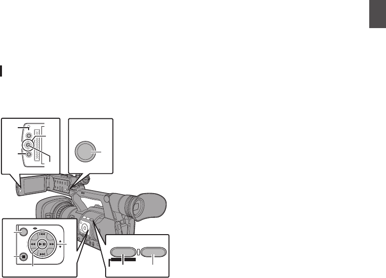
Basic Operations in Menu
Screen
0Press the [MENU/THUMB] button on the side
control panel of the camera recorder or on the
LCD monitor to display the menu screen on the
LCD monitor and viewfinder.
0Various settings for shooting and playback can
be configured on the menu screen.
0There are two types of menu screens - [Main
Menu] and [Favorites Menu].
0[Main Menu] contains all the setting items of the
camera recorder, classified according to
functions and uses, while [Favorites Menu]
allows users to customize the menu items freely.
(A P108 [Adding/Editing Frequently Used
Menu Items (Favorites Menu)] )
0The operating procedures and main screen
displays are the same for both menus.
0The menu screen can also be displayed on
external monitors connected to the video signal
output terminal.
(A P100 [ Display On TV ] )
Operation Buttons
Use the operation buttons on the side control panel
of the camera recorder or the buttons on the LCD
monitor to operate the menu.
.
AE LEVEL
MENU/THUMB
CANCEL
FOCUS ASSIST/1 OIS / 2
TIME CODE
MENU/THUMB
CANCEL
DISPLAY
A
D
B
C
A
B
C
D
E F
G
A[MENU/THUMB] Button
0Displays the menu screen. The [Main
Menu] screen is displayed by default.
0During normal usage, [Main Menu] is
displayed if the previous menu operation
ended at [Main Menu], and [Favorites
Menu] if the previous menu operation ended
at [Favorites Menu].
0Press this button to close the menu screen
during menu display and return to the normal
screen.
0Pressing and holding down the button while
the menu is displayed switches the [Main
Menu] screen to the [Favorites Menu] or vice
versa.
B[CANCEL] Button
Cancels settings and returns to the previous
screen.
CSet Button (R)
Sets the values and items.
DCross-shaped Button (JKH I)
J: Moves the cursor upward.
K: Moves the cursor downward.
H: Moves back to the previous item.
I: Moves forward to the next item.
E[FOCUS ASSIST/1] Button
Adds the selected menu or submenu item to the
[Favorites Menu].
(A P108 [Adding/Editing Frequently Used
Menu Items (Favorites Menu)] )
F[OIS/2] Button
Resets settings in the [TC Preset] or [UB
Preset] setting screen. This button is disabled
in other screens.
G[DISPLAY] Button
Switches between the [Main Menu] and
[Favorites Menu] screens.
Basic Operations in Menu Screen 85
Menu Display and Detailed Settings
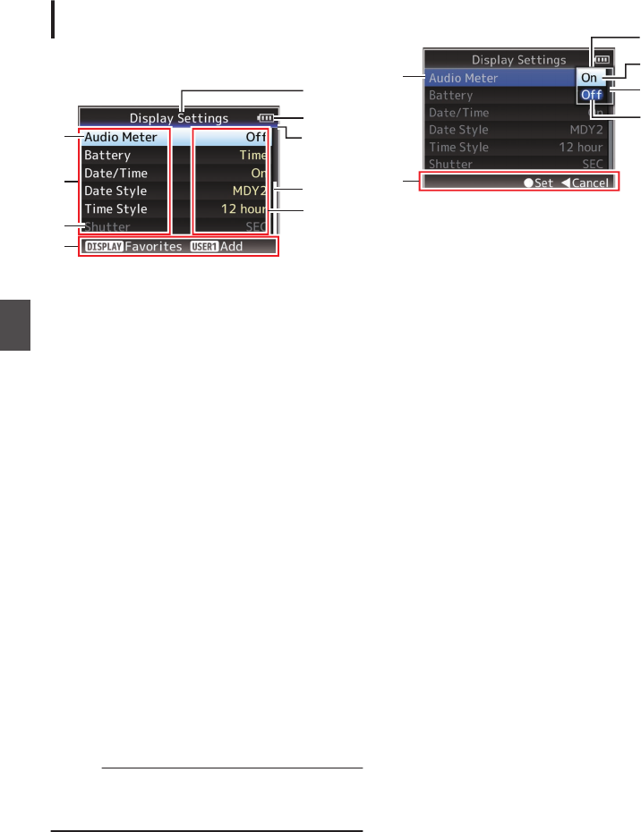
Display and Description of the Menu
Screen
Selecting Menu Items
.
H
I
F
E
B
D
G
A
C
ACursor
Indicates the selected item. Use the cross-
shaped button (JK) to move the cursor
BMenu Item
0Displays the names of the menu item and
sub-menu.
0Menu items with [...] after them indicates that
there is a sub-menu to access.
CFixed Item
Items that cannot be changed are displayed in
gray and cannot be selected.
DOperation Guide
Guide for the current operation buttons.
ESetting Value
Setting values for the menu items.
For menus with sub-menus, values are not
displayed.
FScroll Bar
Indicates the scroll position.
GHeader
Indicates the current menu type with the line
color.
Blue : [Main Menu] Screen
Green : [Favorites Menu] (Operation
screen)
Magenta : [Favorites Menu] (Editing screen)
HRemaining Battery Power
(A P26 [Power Status Display] )
Memo :
0If the battery in use is not a recommended one,
the battery mark which indicates the battery
level may not appear.
IMenu Title
Title of the currently displayed menu.
Changing Setting Values
.
D
F
A
C
B
E
AMenu Item to Change
Menu item to be changed.
A list of setting values F appears in a pop-up.
BOperation Guide
Guide for the current operation buttons.
CSetting Values Before Change
Setting values before changing. The
background of the item is displayed in blue.
DScroll Bar
Indicates the scroll position.
ECursor
Indicates the selected item. Use the cross-
shaped button (JK) to move the cursor
FList of Setting Values
0A pop-up displaying a list of setting values for
selection.
0The height of the pop-up depends on the
number of settings available. Use the scroll
bar D to confirm the current display status.
86 Basic Operations in Menu Screen
Menu Display and Detailed Settings

Text Input with Software Keyboard
Use the software keyboard to enter the [Setup
File] subname and [Clip Name Prefix].
Entering a subname
(A P121 [Configuring Setup Files] )
.
G
A
E
H
C
B
D
F
Entering the [Clip Name Prefix]
(A P107 [ Clip Name Prefix ] )
.
A
E
H
C
B
D
ACharacter Entry Field
0Field for entering the title.
0You can enter up to 8 characters for the
[Setup File] subname or up to 4 characters
for the [Clip Name Prefix].
BCharacter Cursor
Select a character using the key cursor D, and
press the Set button (R) to input the selected
character at the position of the character cursor.
The character cursor moves to the next position
on the right each time a character is input.
The cursor can be moved using the arrow keys
H.
CCharacter Keys
Use the cross-shaped button (JKHI) to move
the key cursor D to the character you want to
enter.
DKey Cursor
Indicates the currently selected character or
item. Use the cross-shaped button (JKHI) to
move the cursor.
EConfirmation Buttons
0Select [Set]/[Store] and press the Set button
(R) to confirm the title.
0Select [Cancel] and press the Set button (R)
on the side control panel of the camera
recorder to abort character input and return
to the previous screen.
F[SP] Space Key
Select [SP] and press the Set button (R) on the
side control panel of the camera recorder to
enter a space at the current position of the
character cursor B.
G[3 ] Backspace Key
Select [3 ] and press the Set button (R) on the
side control panel of the camera recorder to
delete the character on the left of the character
cursor B.
HArrow Keys
Moves the position of the character cursor B.
ICharacter Switch Button
Switches the character buttons C to the upper
case, lower case, and symbols.
Basic Operations in Menu Screen 87
Menu Display and Detailed Settings

Menu Screen Hierarchical
Chart
Main Menu... ......................................... (A P 88)
- Camera Function... ............................ (A P 89)
- Bars ............................................... (A P 89)
- OIS ................................................ (A P 89)
- Flicker Correction .......................... (A P 89)
- Shutter ........................................... (A P 89)
- AE Level ........................................ (A P 89)
- AE Speed ...................................... (A P 89)
- AGC Limit ...................................... (A P 89)
- Smooth Trans ................................ (A P 89)
- GAIN L ........................................... (A P 89)
- GAIN M .......................................... (A P 89)
- GAIN H .......................................... (A P 89)
- AE LEVEL SW ............................... (A P 89)
- Dynamic Zoom .............................. (A P 89)
- Handle Zoom Speed ..................... (A P 89)
- AF Speed ...................................... (A P 90)
- AF Assist ....................................... (A P 90)
- User Switch Set... .......................... (A P 90)
- Camera Process... ............................ (A P 92)
- Detail ............................................. (A P 92)
- Adjust... ................................... (A P 94)
- Master Black ................................. (A P 92)
- Black Toe ...................................... (A P 92)
- White Clip ...................................... (A P 93)
- Gamma ......................................... (A P 93)
- White Balance... ............................ (A P 93)
- Color Matrix ................................... (A P 93)
- Adjust... ................................... (A P 93)
- Color Gain ..................................... (A P 93)
- Reset Process ............................... (A P 93)
- TC/UB... ............................................ (A P 95)
- TC Generator ................................ (A P 95)
- TC Preset ...................................... (A P 95)
- UB Mode ....................................... (A P 95)
- Drop Frame ................................... (A P 95)
- LCD/VF... .......................................... (A P 96)
- Shooting Assist... ........................... (A P 97)
- Marker Settings... .......................... (A P 97)
- Display Settings... .......................... (A P 98)
- LCD + VF ....................................... (A P 96)
- VF Bright ....................................... (A P 96)
- VF Contrast ................................... (A P 96)
- LCD Contrast ................................. (A P 96)
- LCD Backlight ............................... (A P 96)
- LCD Mirror ..................................... (A P 96)
- A/V Set... ......................................... (A P 100)
- Video Set... .................................. (A P 100)
- Audio Set... .................................. (A P 101)
- System... ......................................... (A P 103)
- Record Set... ............................... (A P 104)
- Media... ....................................... (A P 103)
- Setup File... ................................. (A P 103)
- Auto Power Off ............................ (A P 104)
- Tally Lamp ................................... (A P 104)
- Language .................................... (A P 104)
- Reset All ...................................... (A P 104)
- Date/Time .................................... (A P 104)
- Time Zone ................................... (A P 104)
- Reserved ..................................... (A P 104)
- System Information ...................... (A P 104)
Memo :
0Some menus cannot be set depending on the operating mode or status of the camera recorder. These
items are displayed in gray, and they cannot be selected.
0Setting value with the R mark is the factory default.
88 Menu Screen Hierarchical Chart
Menu Display and Detailed Settings

Camera Function Menu
Menu screen for specifying operation settings
during shooting.
This item can only be selected in the Camera
mode.
Bars
For setting whether to output color bars.
[Setting Values: On, ROff]
Memo :
0The audio test signals (1 kHz) can be output
simultaneously with the color bar output.
(A P102 [ Test Tone ] )
OIS
For setting whether to enable image stabilizer.
When “On” is selected, set the Level.
[Setting Values: On, ROff]
9Level
For setting the level of the image stabilizer.
[Setting Values: High, RNormal]
Memo :
0When “High” is selected, correcting severe
camera shake may cause the area surrounding
the image to darken.
0When “High” is selected, the angle of view
becomes narrower at the wide angle end.
Flicker Correction
For setting whether to adjust image flicker that
occurs under a fluorescent light.
[Setting Values: On, ROff]
Shutter
For specifying shutter-related settings.
Use this item to set to “Step” (fixed value) or
“Variable” when operating with the cross-shaped
button (JK) on the right side.
0Variable:
Sets to variable scan. Use this setting such as
when shooting a PC monitor.
0Step:
Sets to step shutter, which switches the shutter
speed by a fixed value.
[Setting Values: Variable, RStep]
AE Level
For setting the convergence level during AE (Auto
Exposure).
This can also be adjusted using the cross-shaped
button (HI) on the right side.
[Setting Values: -6 to +6 (R0)]
AE Speed
For setting the convergence speed during AE (Auto
Exposure).
[Setting Values: RFast, Middle, Slow]
AGC Limit
For setting the maximum gain value of “AGC”,
which electrically boosts the sensitivity level
according to the brightness automatically.
[Setting Values: R24dB, 18dB]
Smooth Trans
For setting the shock reduction function, which
slows down the sudden change when switching
with the [GAIN] or [WHT BAL] selection switch.
[Setting Values: Fast, Middle, Slow, ROff]
Memo :
0This function is disabled when the [FULL AUTO
ON/OFF] switch is set to “ON” or when Scene
Select mode is activated.
GAIN L, GAIN M, GAIN H
For setting the gain value of each position on the
[GAIN] selection switch.
When the [FULL AUTO ON/OFF] switch is set to
“ON” or when Scene Select mode is activated, the
setting is fixed at “AGC”.
[Setting Values: 24dB, 21dB, 18dB, 15dB, 12dB,
9dB, 6dB, 3dB, 0dB]
(Default values GAIN L: 0dB, GAIN M: 6dB, GAIN
H: 12dB)
AE LEVEL SW
For specifying the operation of the cross-shaped
button (HI) on the right side.
0Enable:
Enables the button.
0Disable:
Disables the button.
[Setting Values: Enable, RDisable]
Dynamic Zoom
For setting whether to enable the dynamic zoom
function.
[Setting Values: On, ROff]
Handle Zoom Speed
This function allows you to set the zoom speed of
the zoom lever at the handle when the [ZOOM FIX/
VAR/OFF] switch is set to “FIX”.
[Setting Values: 1 to 8 (R 5)]
Camera Function Menu 89
Menu Display and Detailed Settings

AF Speed
For setting the AF operation speed.
[Setting Values: Fast, RMiddle, Slow]
AF Assist
For setting whether to shift the auto focus point
when the focus/zoom ring is turned during Auto
Focus (AF).
0Area:
This option allows you to shift the auto focus
point to the left, center, right, or near and far
directions by turning the focus/zoom ring during
AF.
Selecting this option displays the icon in
the area.
0Far/Near:
This option allows you to shift the auto focus
point to near and far directions by turning the
focus/zoom ring during AF.
0Off:
Sets the AF Assist function to “Off”.
[Setting Values: Area, Far/Near, ROff]
(A P45 [AF Assist Function] )
Memo :
0This setting is effective only when the [FOCUS]
switch is set to “AUTO”.
0The manual focus adjustment mode is
temporarily activated by turning the focus/zoom
ring in the AF mode. If the focus ring is not
operated for a certain time, the camera recorder
returns to the AF mode.
0When the [FOCUS/ZOOM] operation switch is
set to “ZOOM”, [AF Assist] is fixed at “Off”.
User Switch Set...
For specifying user button related settings.
(A P90 [User Switch Set Item] )
User Switch Set Item
USER1 to USER7, LCD KEY▲, LCD KEY▶,
LCD KEY▼, LCD KEY◀
By assigning one of the following functions to each
of the [FOCUS ASSIST/1], [OIS/2], [LOLUX/3], [AE
LOCK/4], [ZEBRA/5], [MARKER/6], [C.REVIEW/7]
buttons or the cross-shaped buttons on the LCD
monitor, these buttons can be used to control the
assigned function (on/off, start, switch).
Set according to the shooting conditions. Usable
only in the Camera mode.
[Setting Values: None, Bars, Lolux, AE Lock,
Beautiful Skin, Face Detect, OIS, One Push Iris,
Push AF/AF Lock, Preset Zoom1, Preset Zoom2,
Preset Zoom3, White Balance, Zebra, Marker,
Focus Assist, Expanded Focus, LCD Backlight,
Backup Trig, Clip Cutter Trig, OK Mark, Clip
Review, Load Picture File]
Front REC
For setting the function of the [REC] button located
below the lens at the front of the unit.
0REC:
Functions as a record button for starting/ending
recording.
0AWB:
When the [WHT BAL B/A/PRESET] selection
switch is set to “A” or “B” in the Manual White
Balance mode, it functions as an AWB startup
button. If the [WHT BAL B/A/PRESET] selection
switch is set to “PRESET”, it functions as a
button for switching between two color
temperature settings.
(A P54 [Manual White Balance Mode (Manual
Switching)] )
0None:
Disabled.
[Setting Values: RREC, AWB, None]
Clip Review
For specifying the operation when any of the
[USER1]-[USER7], [LCD KEY▲], [LCD KEY▶],
[LCD KEY▼], or [LCD KEY◀] items is set to “Clip
Review”.
0Last 5sec:
Views about 5 seconds of the clip from the
ending.
0Top 5sec:
Views about 5 seconds of the clip from the
beginning.
0Clip:
Views the entire clip.
[Setting Values: RLast 5sec, Top 5sec, Clip]
90 Camera Function Menu
Menu Display and Detailed Settings

Expanded Focus
For specifying the operation when any of the
[USER1]-[USER7], [LCD KEY▲], [LCD KEY▶],
[LCD KEY▼], or [LCD KEY◀] items is set to
“Expanded Focus”.
0Toggle:
Pressing the button assigned with “Expanded
Focus” each time switches the “Expanded
Focus” function to on or off.
0Momentary:
The “Expanded Focus” function is enabled
during the interval while the button assigned with
“Expanded Focus” is pressed.
0Limited Time:
Activates the timer.
During autofocus, the [Expanded Focus] feature
turns off about 3 seconds after it is turned on.
During manual focus, the [Expanded Focus]
feature turns off about 3 seconds after you stop
operating the focus/zoom ring.
[Setting Values: RToggle, Momentary, Limited
Time]
9Ring
For setting the focus/zoom ring operation.
0SW Set:
This follows the settings of the [FOCUS/
ZOOM] operation switch.
0Focus:
When the Expanded Focus function is activated,
focusing operation is possible regardless of the
settings of the [FOCUS/ZOOM] operation
switch.
[Setting Values: RSW Set, Focus]
Camera Process Menu
Menu screen for adjusting the quality of camera
images.
This item cannot be selected in the Media mode
and Scene Select mode.
Detail
For adjusting the contour (detail) enhancement
level.
Increasing the value increases the sharpness of
the contour.
[Setting Values: -10 to +10, Off (R0)]
9Adjust...
For specifying the detailed settings of the contour
(detail).
(A P94 [Detail/Adjust Item] )
Memo :
0This item cannot be selected when [Detail] is set
to “Off”.
Master Black
For adjusting the pedestal level (master black) that
serves as the reference black.
Increasing the value increases the pedestal.
[Setting Values: -50 to +50 (R0)]
Black Toe
Process the dark areas according to the balance of
bright and dark areas in the image to adjust the
overall balance of contrast.
For altering the gain of dark areas. Adjust this item
according to the condition of the captured video
signals.
0Stretch:
Increases the gain of dark areas in an image to
stretch the signals of these areas only, thereby
showing the contrast between bright and dark
areas more clearly.
Specify the amount of stretch with [Stretch
Level].
0Normal:
Normal condition.
0Compress:
Compresses the gain of dark areas to increase
the contrast when the entire image appears
bright and contrast is weak. Specify the
compression amount with [Compress Level].
[Setting Values: Stretch, RNormal, Compress]
92 Camera Function Menu
Menu Display and Detailed Settings

Detail/Adjust Item
V/H Balance
For setting the H/V balance to enhance contour
(detail) in the horizontal (H) or vertical (V) direction.
0H+1 to H+4:
Increasing the value enhances contour in the
horizontal direction.
0V+1 to V+4:
Increasing the value enhances contour in the
vertical direction.
[Setting Values: H+1 to H+4, RNormal, V+1 to V+4]
Memo :
0When [System] under [Record Format] is set to
“SD”, this item is fixed at “Normal”.
White Balance Item
Preset Temp.
For setting the color temperature when the [WHT
BAL] switch is set to “PRESET”.
For details, refer to “[Adjusting the White Balance]
(A P 53)”.
Alternative Temp.
For setting the alternative color temperature in the
Preset mode.
When the [WHT BAL] switch is set to “PRESET”,
pressing the [y] button each time switches the
color temperature setting in the Preset mode.
([Preset Temp.] 1 [Alternative Temp.])
For details, refer to “[Adjusting the White Balance]
(A P 53)”.
AWB Paint
For adjusting the R (red)/B (blue) component in the
AWB (Auto White Balance) mode.
For details, refer to “[Adjusting the White Balance]
(A P 53)”.
0Increase the number:
Strengthens the red/blue.
0Decrease the number:
Weakens the red/blue.
[Setting Values: -32 to +32 (R 0)]
Memo :
0This item is selectable when the [WHT BAL]
switch on the right of the camera recorder is set
to “A” or “B”. When “PRESET” is set, this item
appears as “---” and cannot be selected.
0
Different values can be specified for “A” and “B”.
0After the [y] (Auto White Balance) button is
pressed to readjust the white balance while
[Clear Paint After AWB] is set to “On”, R and B
values switch automatically to “0”.
Clear Paint After AWB
For specifying whether to clear the [AWB Paint] (R
value and B value) settings after executing AWB
(Auto White Balance).
0On:
Sets the [AWB Paint] (R value and B value)
settings to “0” after executing AWB (Auto White
Balance).
0Off:
Does not change the [AWB Paint] (R value and
B value) settings after executing AWB (Auto
White Balance).
[Setting Values: ROn, Off]
FAW Paint
For adjusting the R (red)/B (blue) component
during FAW (Full Auto White Balance) mode.
0Increase the number:
Strengthens the red/blue.
0Decrease the number:
Weakens the red/blue.
[Setting Values: -32 to +32 (R 0)]
94 Camera Process Menu
Menu Display and Detailed Settings

LCD/VF Menu
Item for specifying settings related to the LCD
monitor or viewfinder screen.
This menu screen can be used to specify settings
related to the Focus Assist mode, zebra pattern
display, screen size, marker, and safety zone. In
addition, it is also used for selecting whether to
display characters on the LCD monitor or
viewfinder screen, as well as for adjusting the
picture quality of the LCD monitor.
Shooting Assist...
Menu for setting the Shooting Assist function.
(A P97 [Shooting Assist Item] )
Marker Settings...
For setting items such as the safety zone and
center mark.
(A P97 [Marker Settings Item] )
Display Settings...
For specifying display-related settings.
(A P98 [Display Settings Item] )
LCD + VF
For selecting a method to switch between the LCD
monitor and viewfinder screen displays.
(A P32 [Adjusting the LCD Monitor and
Viewfinder] )
0On:
Displays images on the viewfinder at all times.
0Off:
Turns off the viewfinder screen display when the
LCD monitor is turned on.
[Setting Values: On, ROff]
VF Bright
For setting the brightness of the viewfinder screen.
Increasing the value increases the brightness.
[Setting Values: -10 to +10 (R 0)]
VF Contrast
For setting the difference in luminance between the
darkest and brightness areas in the viewfinder
screen.
Increasing the value increases the contrast.
[Setting Values: -10 to +10 (R 0)]
LCD Contrast
For setting the difference in luminance between the
darkest and brightness areas in the LCD monitor.
Increasing the value increases the contrast.
[Setting Values: -10 to +10 (R 0)]
LCD Backlight
For setting the brightness of the LCD monitor
backlight.
Increasing the value increases the brightness.
[Setting Values: -1, 0, R +1]
LCD Mirror
For specifying the image display method when
facing the LCD monitor.
Select “Mirror” to display the image after laterally
inverting it. (Mirror display)
(A P32 [Adjusting the LCD Monitor and
Viewfinder] )
[Setting Values: Mirror, RNormal]
Memo :
0The setting of this item is valid only in Camera
mode.
0During color bar, menu screen and status
screen display, the “Mirror” setting is disabled.
(A P119 [Color Bar Output] )
96 LCD/VF Menu
Menu Display and Detailed Settings

Shooting Assist Item
Focus Assist
For setting whether to add color to the contour of
the focused image upon switching the image to
black-and-white.
[Setting Values: On, ROff]
9Ring
For setting the focus/zoom ring operation.
0SW Set:
This follows the settings of the [FOCUS/
ZOOM] operation switch.
0Focus:
When the Focus Assist function is activated,
focusing operation is possible regardless of the
settings of the [FOCUS/ZOOM] operation
switch.
[Setting Values: RSW Set, Focus]
9Color
For setting the display color of the focused area
when Focus Assist is activated.
[Setting Values: RBlue, Green, Red]
Zebra
For selecting whether to display zebra patterns at
the bright areas of the subject.
Select “On” to display zebra patterns or “Off” to
hide.
[Setting Values: On, ROff]
9Top
For setting the maximum luminance level for the
zebra pattern display.
[Setting Values: Over, 100%, 98%, 95% to 5% (in
5% increments)] (R80%)
9Bottom
For setting the minimum luminance level for the
zebra pattern display.
[Setting Values: 100%, 98%, 95% to 0% (in 5%
increments)] (R70%)
Memo :
0The relation between Top and Bottom is such
that Top>Bottom always holds. To maintain this
relation during setting, the setting value is
automatically corrected.
Focus Assist & Zebra
For selecting the operation when [Focus Assist]
and [Zebra] are used simultaneously.
0Standard: The focus assist outlines will
overlapped the zebra pattern.
0ALT: The focus assist outlines will not
overlapped the zebra pattern, however, flicker
may occur on the zebra area.
[Setting Values: Standard, RALT]
Marker Settings Item
For setting the marker and safety zone, which are
useful in helping you determine the angle of view
for the image according to the shooting purpose.
(A P119 [Marker and Safety Zone Displays
(Camera Mode Only)] )
Memo :
0During Clip Review or when in the Media mode,
the markers do not appear regardless of the
setting.
Marker
For setting whether to display marker, safety zone,
and center marks on the screen.
[Setting Values: On, ROff]
9Grid Marker
For setting whether to display a 3x3 grid on the
screen.
[Setting Values: On, ROff]
Memo :
0When [Grid Marker] is set to “On”, [Aspect
Ratio], [Aspect Marker], and [Safety Zone] do
not function.
9Aspect Ratio
For selecting the final image aspect ratio to be used
from the overall angle of view.
[Setting Values: 16:9(+4:3), 2.35:1, 1.85:1, R16:9,
1.75:1, 1.66:1, 14:9, 13:9, 4:3, 2.35:1 Center,
2.35:1 Top, 1.85:1 Center, 1.85:1 Top]
Memo :
0When [System] B [Record Set] B [Record
Format] B [SD Aspect] is set to “4:3”, this item
is fixed at “4:3” and cannot be selected.
(A P105 [ SD Aspect ] )
LCD/VF Menu 97
Menu Display and Detailed Settings

9Aspect Marker
For specifying how boundary markers are to be
used to indicate the parts of an image that are
beyond the range of the aspect ratio selected in
[Aspect Ratio].
0Line+Halftone:
Displays the boundary using lines, and areas
outside the boundary in halftone.
0Halftone:
Displays areas outside the boundary in halftone.
0Line:
Displays the boundary using lines.
0Off:
Hides the boundary markers.
[Setting Values: Line+Halftone, Halftone, Line,
ROff]
Memo :
0When [Aspect Ratio] is set to “16:9” or
“16:9(+4:3)”, this item is fixed at “Off” and cannot
be selected.
9Safety Zone
For setting the percentage of area that is to be
deemed as valid area (Safety Zone) within the
boundary of the aspect ratio selected in [Aspect
Ratio].
[Setting Values: 95%, 93%, 90%, 88%, 80%, ROff]
9Center Mark
For specifying whether to display a mark to indicate
the screen center within the aspect ratio selected
in [Aspect Ratio].
[Setting Values: ROn, Off]
Display Settings Item
This menu is used to set the displays on the LCD
monitor and viewfinder screen.
Zoom
For setting the display method of the zoom
position.
0Number:
Displays the zoom position in numbers (0-99).
0Bar:
Displays the zoom position in a bar.
0Off:
Does not display the zoom position.
[Setting Values: Number, RBar, Off]
Focus
For setting the display method of the approximate
distance to the subject in focus during manual
focus.
0Feet:
Displays the focus in feet.
0Meter:
Displays the focus in meters.
0Off:
Does not display the focal length during focus.
[Setting Values: Feet, RMeter, Off]
Record Format
For setting whether to display the video format
during recording or playback.
[Setting Values: ROn, Off]
Media Remain
For setting whether to display the remaining space
of the recording SD card.
[Setting Values: ROn, Off]
Memo :
0When the remaining space warning is
displayed, the information appears even when
“Off” is selected.
0The displayed time is an estimate.
TC/UB
For specifying whether to display the time code
(TC) or user’s bit (UB) rate in the display on the LCD
monitor and viewfinder screen.
[Setting Values: UB, RTC, Off]
98 LCD/VF Menu
Menu Display and Detailed Settings

Audio Meter
For specifying whether to display the audio level
meter on the LCD monitor and viewfinder screen.
[Setting Values: ROn, Off]
Battery
For setting the display of the remaining battery
power in the display on the LCD monitor and
viewfinder screen.
The battery information appears only on the
Display 2 screen in Camera mode.
(A P112 [Display 2 screen] )
0Time:
Displays the remaining battery power in
minutes. (min)
0Capacity%:
Displays the remaining battery power in
percentage. (%)
0Voltage:
Displays the current battery voltage in units of
0.1 V. (V)
0Off:
The remaining battery power is not displayed.
[Setting Values: RTime, Capacity%, Voltage, Off]
Memo :
0
The battery mark that appears before the “Time”,
“Capacity%” or “Voltage” value changes
according to the remaining battery power.
In addition, the plug mark is added during
charging.
4 S: 10 % and below
D R: 11 % to 30 %
C Q: 31% to 70 %
B P: 71 % to 100 %
0When the remaining battery power is low, “RES”
instead of the value is displayed.
Replace the battery as soon as possible.
0The remaining battery power and remaining
time are intended as reference values for the
shooting duration.
0The time, capacity or voltage will not be
displayed during charging.
Date/Time
For specifying whether to display the date and time
in the display on the LCD monitor and viewfinder
screen.
[Setting Values: ROn, Off]
Date Style
For setting the date display sequence for display
on the LCD monitor and viewfinder screen as well
as for time stamp recording.
Display examples of the setting values are as
follows.
0DMY2: 30 Jun 2016
0DMY1: 30-06-2016
0MDY2: Jun 30, 2016
0MDY1: 06-30-2016
0YMD: 2016-06-30
[Setting Values: DMY2, RDMY1, MDY2, MDY1,
YMD]
Time Style
For setting the time display for display on the LCD
monitor and viewfinder screen as well as for time
stamp recording.
[Setting Values: R24hour, 12hour]
LCD/VF Menu 99
Menu Display and Detailed Settings

A/V Set Menu
Menu screen for video output and audio.
Video Set...
For specifying video output-related settings.
(A P100 [Video Set Item] )
Audio Set...
For specifying audio-related settings.
(A P101 [Audio Set Item] )
Video Set Item
Display On TV
For setting whether to display the display and menu
characters on the external monitor.
[Setting Values: On, ROff]
HDMI out
For setting the terminal to output the video.
[Setting Values: On, ROff]
9Resolution
For selecting the resolution of video output from the
[HDMI] terminal according to the monitor to be
connected.
[Setting Values: 576i, 576p, 480i, 480p, 720p,
R1080i, 1080p]
Memo :
0The selectable options vary according to the
setting in [System]/[Resolution]/[Frame & Bit
Rate] of [System] B [Record Set] B [Record
Format].
0Cross conversion output is not possible.
9Color
0For setting the color format of HDMI signals.
0This item can be set only when [HDMI out] is set
to “On”.
[Setting Values: RGB, RAuto]
9Enhance
0For setting the color range of HDMI signals.
When connecting to a PC monitor, set this to
“On”.
0This item can be set only when [HDMI out] is set
to “On”.
[Setting Values: On, ROff]
9Rec Trigger
For setting whether to superimpose trigger signals
in tandem with the [HDMI] terminal as well as the
[REC] button on the camera body.
When a compatible device is connected,
recording/stop control signals are output in tandem
with the operation of the [REC] button.
The record trigger output status to the connected
device is indicated by REC B/STBYB on the
display screen.
0On:
Superimposes the trigger signals in tandem with
the [HDMI] terminal as well as the [REC] button
on the camera body and outputs the recording/
stop control signals to the compatible device.
0Off:
Does not superimpose the trigger signals.
[Setting Values: On, ROff]
Memo :
0Even if REC B/STBYB is displayed on the
display screen, the compatible device may not
necessarily be recording.
0When [Main Menu] B [A/V Set] B [Video Set] B
[HDMI out] is set to “Off”, [Rec Trigger] is fixed
at “Off” and cannot be selected.
0When [Main Menu] B [System] B [Record Set]
B [Rec Mode] is set to “Interval Rec” or “Frame
Rec”, [Rec Trigger] is fixed at “Off” and cannot
be selected.
0Set to “Off” if connecting to a device that does
not support record trigger.
9TC
For setting whether to superimpose time code to
the [HDMI] terminal.
[Setting Values: On, ROff]
Memo :
0Set to “Off” if connecting to a device that does
not support HDMI TC.
100 A/V Set Menu
Menu Display and Detailed Settings

SD Aspect
For setting the style of displaying down-converted
images on a 4:3 aspect ratio screen.
0Side Cut:
Displays image with the left and right sides cut
off.
0Letter:
Displays as a wide image with the top and
bottom blackened.
0Squeeze:
Displays image that is squeezed horizontally.
[Setting Values: Side Cut, Letter, RSqueeze]
Memo :
0When [Record Format] B [System] is set to
“SD”, and when [SD Aspect] is set to “4:3”, this
item appears as “---” and cannot be selected.
(A P105 [ System ] )
SD Set Up
For selecting whether to add a setup signal to the
video signal output from the [AV] output terminal.
Setup signals are added when “7.5%” is selected.
[Setting Values: 7.5%, R0.0%]
Memo :
0Depending on the menu settings of the camera
recorder and the condition of the cable
connected to it, the setup signal setting may be
fixed at “0.0%”. “0.0%” is displayed in gray in this
case.
0When [Main Menu] B [System] B [Record Set]
B [Record Format]B[Frame & Bit Rate] is set to
“50p” or “50i”, “---” is displayed and selection is
disabled.
Audio Set Item
Input1 Mic Ref.
For setting the reference input level when the
[INPUT1] selection switch is set to “MIC” or “MIC
+48V”.
[Setting Values: -62dB, -56dB, R-50dB, -44dB,
-38dB, -32dB]
Input2 Mic Ref.
For setting the reference input level when the
[INPUT2] selection switch is set to “MIC” or “MIC
+48V”.
[Setting Values: -62dB, -56dB, R-50dB, -44dB,
-38dB, -32dB]
Int. Mic Gain
For setting the sensitivity of the built-in microphone.
[Setting Values: +12dB, +6dB, R0dB]
AUX Gain
For setting the sensitivity of the [AUX] terminal
input.
[Setting Values: +12dB, +6dB, R0dB]
Ref. Level
For setting the audio reference level to be recorded
to the SD card. (Applies to both [CH1/CH2].)
[Setting Values: -12dB, -18dB, R-20dB]
Limiter
For setting the limiter operation.
0Ref. Level:
Sets “Ref. Level” to the maximum recording
level.
0-8dBFS, -5dBFS:
Sets “-8dBFS” or “-5dBFS” to the maximum
recording level.
0Off:
Depending on the settings of the [CH1/CH2
AUTO/MANUAL] selection switches, the
operation may be different as described below.
0The limiter does not function when
“MANUAL” is set.
0The limiter functions at -5 dBFS when
“AUTO” is set.
[Setting Values: Ref. Level, -8dBFS, R-5dBFS, Off]
AGC Response
9Attack Time
Sets the time to activate the limiter.
[Setting Values: Fast, RMiddle, Slow]
9Decay Time
Sets the time to deactivate the limiter operation.
[Setting Values: Fast, RMiddle, Slow]
A/V Set Menu 101
Menu Display and Detailed Settings

AGC Mode
For setting whether to link the limiter operation of
[CH1] and [CH2].
Select “Link” to link or “Separate” to separate.
[Setting Values: Link, RSeparate]
Memo :
0Enabled only when both the [AUX] input terminal
and [INPUT1/INPUT2] input terminal are set to
“LINE” or “MIC”, and CH1/CH2 of the [CH1/CH2
AUTO/MANUAL] switch is set to “AUTO”.
XLR Manual Level
For setting whether to link manual audio
adjustment operation between [INPUT1] and
[INPUT2] terminals.
Select “Link” to link or “Separate” to separate.
When this item is set to “Link”, adjust the recording
level using the [CH1] recording level adjustment
knob.
[Setting Values: Link, RSeparate]
Memo :
0Enabled only when both the [INPUT1/INPUT2]
input terminals are set to “LINE” or “MIC”, and
both [CH1]/[CH2] of the [CH1/CH2 AUTO/
MANUAL] selection switches are set to
“MANUAL”.
0When this item is set to “Link”, [CH2] recording
level adjustment knob is disabled.
Int. Mic Separation
For setting the enhancement level of the stereo
effect of the built-in microphone.
01 to 4:
Enhances the stereo effect. Increasing the value
increases the stereo effect.
0Effect off:
Does not enhance the stereo effect.
0Mono:
Sets the built-in microphone to monaural.
[Setting Values: 1 to 4, Effect off, Mono (R2)]
Memo :
0When any value from 1 to 4 is selected, the
sound quality changes slightly due to the
process of enhancing the stereo effect. This is
normal.
0This menu is enabled when the [CH1]/[CH2]
selection switch is set to “INT”.
Test Tone
For specifying whether to output the audio test
signals (1 kHz) during color bar output.
[Setting Values: On, ROff]
INPUT1/2 Wind Cut
For selecting whether to cut the low frequencies of
the audio input signals (low-cut) when the [INPUT1/
INPUT2] switch is set to “MIC” or “MIC+48V”.
Set this item to reduce wind noise from the
microphone.
0Both:
Enables low-cut on both the [INPUT1] and
[INPUT2] terminals.
0INPUT2:
Enables low-cut on the audio of the [INPUT2]
terminal only.
0INPUT1:
Enables low-cut on the audio of the [INPUT1]
terminal only.
0Off:
Disables low-cut.
[Setting Values: Both, INPUT2, INPUT1, ROff]
Int. Mic Wind Cut
For selecting whether to cut the low frequencies of
the audio input signals (low-cut) from the built-in
microphone. Set this item to “On” to reduce wind
noise from the microphone.
[Setting Values: On, ROff]
Equalizer
You can correct the characteristic and enhance the
sound of the connected microphone using this
equalizer setting.
For setting the audio frequency from a 5-band
equalizer.
0Frequency:
100Hz, 330Hz, 1kHz, 3.3kHz, 10kHz
0Variable level:
± 6dB (1dB step)
Memo :
0Audio will be recorded in the characteristic set
in the equalizer.
0Set all bands to “0dB” to bypass the equalizer.
0When the equalizer level is set to the + side, the
audio may be distorted. In this case, reduce the
recording level in Manual mode.
0If the values of multiple frequencies are
changed, the specified levels and the actual
levels may be different due to interference
between the frequency bands.
0
This function is enabled only when both
[INPUT1/2 Wind Cut] and [Int. Mic Wind Cut] are
set to “Off”.
102 A/V Set Menu
Menu Display and Detailed Settings

Monitor
For setting the audio sound of the [x] terminal to
stereo or mixed sound when the [MONITOR]
selection switch on the LCD monitor is set to
“BOTH”.
0Mix:
Outputs mixed sound (mixed sound of CH1 and
CH2) to both L and R.
0Stereo:
Outputs stereo sound (outputs audio sound of
CH1 to L, and CH2 to R).
[Setting Values: RMix, Stereo]
Memo :
0If both CH1 and CH2 are built-in microphones,
stereo sound is output from the [x] terminal
regardless of the [Monitor] setting.
Alarm Level
For selecting whether to turn on the warning tone
as well as setting the volume.
The warning tone is output from the monitor
speaker or [x] terminal.
[Setting Values: RHigh, Middle, Low, Off]
Audio On FULL AUTO
For setting whether to enable Auto mode for audio
when the [FULL AUTO ON/OFF] switch is set to
“ON”, or when Scene Select mode is activated.
0SW Set:
Sets the audio recording mode following the
[CH1/CH2 AUTO/MANUAL] selection switch
setting.
0Auto:
Sets audio recording mode to the forced auto
mode.
[Setting Values: SW Set, RAuto]
System Menu
This menu screen allows system-related settings.
For specifying recording settings, formatting and
restoring of SD card, tally lamp setting, date/time,
time zone, and other settings.
It can also be used to reset the menu settings to
their default values.
Record Set...
For specifying recorded video-related settings.
(A P104 [Record Set Item] )
Media
9Format Media
For formatting (initializing) an SD card.
Select a card slot (A or B), select [Format] from
[Cancel]/[Format], and press the Set button (R) to
format (initialize) the card.
(A P37 [Formatting (Initializing) SD Cards] )
9Restore Media
For restoring an SD card.
Select a card slot (A or B), and press the Set button
(R) to restore the SD card.
(A P38 [Restoring the SD Card] )
Memo :
0This item appears only when the SD card needs
to be restored. However, it is not selectable
when recording in Camera mode and during Clip
Review.
Setup File
This allows you to save the menu settings as well
as the performance results of shutter speed and
AWB.
It is useful to save settings according to different
shooting conditions.
9Load File...
Loads the settings.
(A P122 [Loading a Setup File] )
9Store File...
Saves the settings.
(A P121 [Saving Setup Files] )
9Delete File...
Deletes the configured file.
(A P123 [Deleting Setup Files] )
A/V Set Menu 103
Menu Display and Detailed Settings

Auto Power Off
For setting whether to turn off the power
automatically when the camera recorder is not
operated for more than 5 minutes when the battery
is used. This function is valid only when the battery
is used.
[Setting Values: On, ROff]
Memo :
0When both the battery and AC adapter are
connected, power from the AC adapter
connection will be used. As such, this function
will not have any effect.
Tally Lamp
For setting whether to light up the tally lamp during
recording, or when the remaining space warning is
displayed.
0On:
Turns on the indicator, indicator blinks.
0Off:
Turns off the indicator, indicator does not blink.
[Setting Values: ROn, Off]
Memo :
0The blinking warning display, such as when the
remaining battery level is low, is enabled in a
setting other than “Off”.
Language
Switches between languages in the menu screen.
[Setting Values: REnglish, Français, Deutsch,
Italiano, Español, Pусский]
Reset All
Resets all menu settings.
Memo :
0[Date/Time] and [Time Zone] cannot be reset.
(A P104 [ Date/Time ] )
(A P104 [ Time Zone ] )
0This item is not selectable when recording in
Camera mode, during Clip Review, and in Media
mode.
Date/Time
For setting the year, month, day, hour, and minute.
Memo :
0The display order of the date (year, month, day)
follows the setting in [Display Settings] B [Date
Style]. However, the 24-hour format is used for
the hour display regardless of the [Time Style]
setting.
(A P99 [ Date Style ] )
Time Zone
For setting the UTC time difference in units of 30
minutes.
[Setting Values: UTC-12:00-UTC-00:30, UTC,
UTC+00:30-UTC+14:00 (in 30 min increments)]
(RUTC)
Memo :
0If [Date/Time] is already set, the [Date/Time]
item is automatically adjusted when [Time
Zone] is altered.
Reserved
For setting the additional function to “On” or “Off”.
9Reserved 1 to Reserved 16
Normally set to “Off”.
[Setting Values: On, ROff]
System Information
9Version
Displays information on the firmware version.
9Open Source License
Displays the license for the open source software
used by this camera recorder.
Record Set Item
Record Format
After setting of all items in the [Record Format]
menu is complete, select [Set] at the bottom of the
screen to apply the new settings on the camera
recorder and switch the recording format. A
“Please Wait...” message appears during
switching.
104 System Menu
Menu Display and Detailed Settings

9System
For selecting a system definition.
0HD:
Records in “HD” (high definition) quality
0SD:
Records in “SD” (standard definition) quality
[Setting Values: RHD, SD]
Caution :
0The selectable options for the [Format],
[Resolution], and [Frame & Bit Rate] settings
vary depending on the setting of this item.
9Format
For selecting the format of the file to be recorded to
the SD card in slot A.
[Setting Values: RQuickTime(MPEG2),
MP4(MPEG2), AVCHD, QuickTime(H.264)]
Memo :
0When [System] is set to “HD” or “SD”, the
recording file format will be the same for both SD
cards in slots A and B.
0When [System] is set to “SD”, this item is fixed
at “QuickTime(H.264)”.
9Resolution
For setting the size of the recorded image when
[System] is set to “HD”. (Horizontal x vertical)
The available options vary according to the
[Format] and [System] settings.
0When MP4(MPEG2) or QuickTime(MPEG2) is
selected:
[Setting Values: R1920x1080, 1440x1080,
1280x720]
0When AVCHD is selected:
[Setting Values: R1920x1080, 1440x1080]
0When QuickTime(H.264) is selected:
Fixed at “1920x1080”
Memo :
0When [System] is set to “HD” or “SD”, the
recording definition will be the same for both SD
cards in slots A and B.
0When [System] is set to “SD”, this item is fixed
at “720x576”.
0The selectable values of [Frame & Bit Rate] vary
according to the setting of this item.
9Frame & Bit Rate
For selecting the recording frame rate and encoding
bit rate for the SD card inserted into slot A.
The selectable options vary according to the settings
of the following items.
Resolution Format Frame & Bit Rate
1920x1080 AVCHD [Setting Values:
60p(HQ), 60i(HQ),
50p(HQ), R50i(HQ),
60i(SP), 50i(SP)]
QuickTime(H.
264)
[Setting Values:
60p(XHQ), 60i(XHQ),
50p(XHQ), 50i(XHQ),
60i(UHQ),
R50i(UHQ)]
Other than
AVCHD and
QuickTime(H.
264)
[Setting Values:
60i(HQ), R50i(HQ)]
1440x1080 AVCHD [Setting Values:
60i(LP), R50i(LP),
60i(EP), 50i(EP)]
Other than
AVCHD
[Setting Values:
60i(HQ), R50i(HQ),
60i(SP), 50i(SP)]
1280x720
MP4(MPEG2)
or
QuickTime(
MPEG2)
[Setting Values:
60p(HQ), R50p(HQ)]
Memo :
0For details on the combinations of usable
[Record Format], refer to the following.
(A P42 [List of Formats] )
0When [System] is set to “SD”, this item is fixed
at “50i”.
0When [System] is set to “HD” or “SD”, the frame
rate and encoding bit rate for recording to the SD
cards in slots A and B will be the same.
9SD Aspect
For setting the aspect ratio of the recorded image
when [System] is set to “SD”.
[Setting Values: R16:9, 4:3]
Memo :
0When [System] is set to “HD”, this item is fixed
at “16:9”.
System Menu 105
Menu Display and Detailed Settings

Rec Mode
For selecting the record mode for recording to the
SD card.
(A P71 [Special Recording] )
[Setting Values: RNormal, Pre Rec, Clip
Continuous, Frame Rec, Interval Rec]
Memo :
0When [Slot Mode] is set to “Backup”, this item is
fixed at “Normal”.
9Pre Rec Time
For setting the pre-recording time when [Rec
Mode] is set to “Pre Rec”.
[Setting Values: R5sec, 10sec, 15sec]
Memo :
0When the frame rate setting in [Main Menu] B
[System] B [Record Set] B [Record Format] B
[Frame & Bit Rate] is set to “XHQ”, “15sec”
cannot be selected.
9Rec Frames
For setting the number of frames to record when
[Rec Mode] is set to “Frame Rec” or “Interval Rec”.
[Setting Values: R1frame, 3frames, 6frames]
9Rec Interval
For setting the recording time interval when [Rec
Mode] is set to “Interval Rec”.
[Setting Values: R1sec, 2sec, 5sec, 10sec, 30sec,
1min, 2min, 5min, 10min, 30min, 1hour]
Slot Mode
For setting the operation of the card slot.
0Series:
Mode that activates the two slots sequentially.
0Dual:
Mode that activates the two slots at the same
time.
(A P68 [Dual Rec] )
0Backup:
Mode that enables recording to slot B without
using the [REC] button. This item is selectable
only when [Rec Mode] is set to “Normal”.
Start or stop the recording using the [Backup
Rec] menu or press the [USER1] to [USER7],
[LCD KEY▲], [LCD KEY▶], [LCD KEY▼], [LCD
KEY◀] button that is assigned with “Backup
Trig”.
(A P69 [Backup Rec] )
Memo :
0When this is set to “Series”, and recordable
media are inserted in both slots, pressing the
[REC] button starts recording only to the card in
the selected slot (active slot).
0When “Series” is selected, and [Record
Format] B [Format] is set to “AVCHD”, the clips
are recorded over the slots seamlessly without
interruption in the video.
0When this is set to “Dual”, and recordable media
are inserted in both slots, pressing the [REC]
button starts simultaneous recording to the
cards in both slots.
9Backup Rec
For starting/stopping backup recording with [REC]/
[STBY].
This item is selectable only when [Slot Mode] is set
to “Backup”.
Memo :
0When recording is stopped due to no remaining
space on the media, etc., this item is fixed at
“STOP” and cannot be selected.
106 System Menu
Menu Display and Detailed Settings

4GB File Spanning(SDXC)
A recording file is automatically split when the size
exceeds 4 GB, but if an SDXC card is used, you
can record clips larger than 4 GB by setting this
option to “Off”. (Up to a maximum of 64 GB or 4
hours)
0On:
Splits a file when it exceeds 4 GB or 30 minutes.
0Off:
Splits a file when it exceeds 64 GB or 4 hours.
[Setting Values: ROn, Off]
Memo :
0To use an SDHC card, set [4GB File
Spanning(SDXC)] to “On”.
0This option is only valid if the SD card used for
recording is of the SDXC format.
0During simultaneous recording, such as Dual
Rec and backup recording, this option is valid
only when the SD cards in both slots are of the
SDXC format.
0This option is valid only when [Record Format]
B [Format] is set to “QuickTime(MPEG2)” or
“QuickTime(H.264)”.
(A P105 [ Format ] )
Recording in DCIM Folder
When “On” is selected, files are recorded to the
DCIM folder of the SD card during MOV recording.
[Setting Values: ROn, Off]
Memo :
0When “Off” is selected, folders containing
recorded clips may not be detectable in the MAC
OS environment.
0To import clips to a Blu-ray disc & HDD recorder
produced by our company, set this item to “Off”
before recording.
LPCM (QuickTime)
For setting the audio recording format of
QuickTime.
[Setting Values: Dual Mono, RStereo]
Time Stamp
For setting whether to display shooting date/time
information in the recorded video.
[Setting Values: On, ROff]
Memo :
0The date/time display style can be changed in
[LCD/VF] B [Display Settings] B [Date Style]/
[Time Style].
(A P99 [ Date Style ] )
(A P99 [ Time Style ] )
0When the date/time is hidden while the menu
screen, status screen or other screen is
displayed, the date/time during this period will
not be recorded to the video. A confirmation
screen appears if you try to display the menu
screen or status screen during recording.
Clip Set
9Clip Name Prefix
For setting the first four characters of the name of
the clip file to be recorded to the SD card.
Enter any of the 38 characters including alphabets
(upper case), numbers (0 to 9), “_” (underscore),
and “-” (hyphen) using the software keyboard.
(A P87 [Text Input with Software Keyboard] )
[Setting Values: xxxG] (The default value of xxx is
the last three digits of the serial number.)
Memo :
0When [Main Menu] B [System] B [Record Set]
B [Record Format] B [Format] is set to
“AVCHD”, this setting is not reflected in the file
name of the clip.
However, it is recorded as the display name of
the clip in the thumbnail display.
0“-” (hyphen) in the [Clip Name Prefix] will be
replaced with “_” (underscore) only when
recording clips to the DCIM folder.
9Reset Clip Number
For assigning a new number (Clip Number) by
resetting it (0001).
Select [Reset] and press the Set button (R) to reset
the number.
When [Format] is set to “AVCHD”, the clip number
is reset to “00000”.
When other clips exist on the SD card, the smallest
available number is used after reset.
0Example:
If the [Clip Name Prefix] is “ABCD”, and
“ABCD0001” already exists on the SD card,
“ABCD0002” will be assigned.
System Menu 107
Menu Display and Detailed Settings

Adding/Editing
Frequently Used Menu
Items (Favorites Menu)
You can select and add/edit frequently used menu
items freely to create a personal menu screen
(Favorites Menu).
Memo :
0[Favorites Menu] is only enabled in the Camera
mode. [Favorites Menu] remains unchanged
even when the recording format changes.
0Up to 20 menu items can be added.
0Added items in [Favorites Menu] will not be reset
even when [Main Menu] B [Reset All] is
executed.
0Long descriptive names may be displayed for
the menu items in [Favorites Menu] to enable
better understanding.
.
AE LEVEL
MENU/THUMB
CANCEL
FOCUS ASSIST/1 OIS / 2
TIME CODE
MENU/THUMB
CANCEL
DISPLAY
Adding Menu Items to Favorites Menu
1Press the [MENU/THUMB] button to open
the [Main Menu] screen.
2Select the menu or submenu item to add.
.
2
Memo :
0
Adding items to [Favorites Menu] cannot be
performed in the following cases. [USER1 Add]
is displayed in gray in the operation guide.
0Selected item is already added to [Favorites
Menu].
0Number of menu items that can be added (20
items) is exceeded.
3Press the [FOCUS ASSIST/1] button.
A screen to confirm the addition appears.
4Select [Add] and press the Set button (R).
The selected menu item is added to [Favorites
Menu].
.
4
108 Adding/Editing Frequently Used Menu Items (Favorites Menu)
Menu Display and Detailed Settings

Editing Favorites Menu
You can delete or change the order of the items
added to [Favorites Menu].
Deleting Items from [Favorites Menu]
1Open the [Favorites Menu] screen.
APress the [MENU/THUMB] button to
open the [Main Menu] screen.
BPress the [DISPLAY] button or press and
hold down the [MENU/THUMB] button to
open the [Favorites Menu] screen.
2Select [Edit Favorites] and press the Set
button (R) or crossed-shaped button (I).
The header turns magenta and the editing
mode is activated.
.
2
Header
(Magenta)
3Select the menu or submenu item to delete.
.
3
4Press the [OIS/2] button.
A delete mark (b) appears at the beginning of
the menu item.
.
Memo :
0When the [OIS/2] button is pressed again while
the menu item with the delete mark (b) is
selected, the menu item will be excluded from
the items to be deleted and the delete mark (b)
disappears.
5Press the [FOCUS ASSIST/1] button.
The option menu to exit the [Favorites Menu]
editing mode appears.
6Select [Save & Exit] and press the Set
button (R).
.
6
Memo :
0Deletion is not complete until the changes are
saved with [Save & Exit].
0To exit the editing mode without deleting any
items, select [Exit without Saving].
0To return to the editing mode, select [Cancel].
Adding/Editing Frequently Used Menu Items (Favorites Menu) 109
Menu Display and Detailed Settings

Changing the Order of Items in [Favorites
Menu]
.
AE LEVEL
MENU/THUMB
CANCEL
FOCUS ASSIST/1 OIS / 2
TIME CODE
MENU/THUMB
CANCEL
DISPLAY
1Open the [Favorites Menu] screen.
Press the [MENU/THUMB] button to open the
[Favorites Menu] screen.
2Select [Edit Favorites] and press the Set
button (R) or crossed-shaped button (I).
The header turns magenta and the editing
mode is activated.
.
2
Header
(Magenta)
3Select the menu or submenu item to move
and press the Set button (R).
The moving mode is activated and a position
selection bar for the move appears.
.
3
Position
Selection Bar
4Select the position to move to with the
cross-shaped button (JK).
Move the position selection bar with the cross-
shaped button (JK) and select a position to
move to.
5Press the Set button (R).
The selected item moves to the new position.
.
5
4
110 Adding/Editing Frequently Used Menu Items (Favorites Menu)
Menu Display and Detailed Settings

6Press the [FOCUS ASSIST/1] button.
The option menu to exit the [Favorites Menu]
editing mode appears.
7Select [Save & Exit] and press the Set
button (R).
.
7
Memo :
0Moving is not complete until the changes are
saved with [Save & Exit].
0To exit the editing mode without saving any
changes, select [Exit without Saving].
0To return to the editing mode, select [Cancel].
Adding/Editing Frequently Used Menu Items (Favorites Menu) 111
Menu Display and Detailed Settings

Display Screen in Camera
Mode
Display 0 screen
This screen displays the event. It is also used to
display warnings only.
.
100min
50min
282min
0
P13000K 1/100
F1. 6
0dB
AE+6
5 . 6 f t
100mi
n
5
0m
i
n
2
82
m
i
n
P13000
K
1
/
1
00
F
1
.
6
0
d
B
AE
+
6
5
.
6
f
t
※2
※1
Y
G
X
A
ca
b
*1 Appears only during warnings
*2 Appears only during operation
Display 1 screen
.
100min
50min
282min
0
P13000K 1/100
F1. 6
0dB
AE+6
12 : 34 : 56
Jan 12, 2016
00:00:00.00
4030 20 10 0
5 . 6 f t
G H I
100mi
n
5
0m
i
n
2
82
m
in
※
A
F
K
J L M
O
Q
R
S
U
T
VWb a
N
P
X
Yc
* Appears only during warnings
Display 2 screen
.
100min
50min
282min
0
P13000K 1/100
F1. 6
0dB
AE+6
12 : 34 : 56
Jan 12, 2016
00:00:00.00
1920x1080
50p HQ
4030 20 10 0
5 . 6 f t P
c
C
F
KG JH I L M
O
Q
R
S
U
T
V
ZX
D
E
B
N
Wb a
YA
AOK Mark
Displayed when OK mark has been appended.
(A P81 [Appending/Deleting OK Mark] )
BVoltage/Battery Power
Displays the current status of the power supply
in use.
(A P26 [Power Status Display] )
Memo :
0Displayed in the Display 0 and Display 1 screens
during warnings only.
CRemaining Space on Media
Displays the remaining recording time of the SD
cards in slot A and slot B separately.
W: Currently selected slot. (White card)
W z: Write-protect switch of SD card is set.
W!INVALID : SD card cannot be read or
written to, or restored.
W!FORMAT : SD card requires
formatting.
W!RESTORE : SD card requires restoring.
W
!INCORRECT
:
0When Record Set is set to other than
“AVCHD”/“SD” with a Class 4 SD card
inserted.
0When the SD card is not supported.
0When an SD card lower than Class 10 is
inserted while in the XHQ mode.
W!REC INH :
0When attempting to record in 50i(HQ)/
50i(SP) to an SD card recorded in
AVCHD60i(HQ)/60i(SP) (or vice versa).
0When an SDHC card is inserted while
[4GB File Spanning(SDXC)] is set to “Off”.
(A P107 [ 4GB File Spanning(SDXC) ] )
Memo :
0This item is not displayed when [Main Menu] B
[LCD/VF] B [Display Settings] B [Media
Remain] is set to “Off”. However, warnings will
be displayed.
(A P98 [ Media Remain ] )
0Displayed on the Display 0 and Display 1
screens only in the case of warnings. (When the
remaining time is shorter than 3 minutes)
The icons appear on all display screens in the
following cases.
0When recording is performed to only one
of the slots while [Main Menu] B [System]
B [Record Set] B [Slot Mode] is set to
“Dual”.
(A P106 [ Slot Mode ] )
0The displayed time is an estimate.
112 Display Screen in Camera Mode
Display/Status Screen
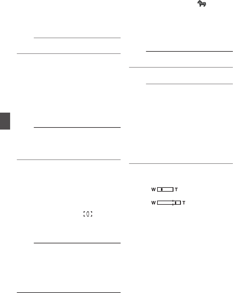
MIris F-Number
Displays F-number of the lens iris.
NGain
0Displays the gain value when in the Manual
Gain mode.
0“LUX30” is displayed when in the low-light
shooting mode.
Memo :
0Displayed in the Display 0 screen only when
there is a change.
OAE Level
0Displayed when the AE function is activated.
0When operated while manual operation is
disabled, “AE” blinks for about 5 seconds.
0When face detection is enabled and [Face
Detect] is set to “AF&AE”, q appears on the
left side of “AE”.
(A P46 [Adjusting the Focusing by Face
Detection] )
PBeautiful Skin
e appears when Beautiful Skin is in
operation.
Memo :
0If [Beautiful Skin] is turned off while the Display
0 screen is displayed, f appears for 3
seconds.
0Displayed in the Display 0 screen only when
there is a change.
QFocus Display
0Displays the approximate distance to the
subject in focus during manual focus.
0When face detection is enabled, q appears
on the left side of e.
(A P46 [Adjusting the Focusing by Face
Detection] )
(A P91 [ Face Detect ] )
0If [Main Menu] B [Camera Function] B [AF
Assist] is set to “Area”, the icon appears
on the left side of e.
(A P90 [ AF Assist ] )
0d appears on the screen while auto focus
is locked.
Memo :
0You can specify the display method (Feet/
Meter) in [Main Menu] B [LCD/VF] B [Display
Settings] B [Focus].
This item will not be displayed when “Off” is
selected.
(A P98 [ Focus ] )
0Displayed in the Display 0 screen only when
there is a change.
RZebra pattern
During zebra pattern display, (zebra icon)
is displayed on the display screen in Camera
mode.
(A P65 [Setting Zebra Pattern] )
SFocus Assist
0“FOCUS” is displayed when auto focus is
activated.
(A P97 [ Focus Assist ] )
Memo :
0Displayed in the Display 0 screen only when
there is a change.
TDate/Time Display
Displays the current date and time.
Memo :
0The date/time display style can be specified in
[Main Menu] B [LCD/VF] B [Display Settings] B
[Date Style]/[Time Style].
(A P99 [ Date Style ] )
(A P99 [ Time Style ] )
0This item is not displayed when [Main Menu] B
[LCD/VF] B [Display Settings] B [Date/Time] is
set to “Off”.
(A P99 [ Date/Time ] )
0When [Main Menu] B [System] B [Record Set]
B [Time Stamp] is set to “On”, this item is not
displayed.
(A P107 [ Time Stamp ] )
UZoom Display
0Displays the zoom position. (Zoom bar or
value)
Dynamic Zoom Off:
.
Dynamic Zoom On:
.
0The zoom bar will only be displayed for 3
seconds after the zoom operation is
activated.
0The value will always be displayed.
0If [Main Menu] B [Camera Function] B
[OIS] B [OIS] is set to “Off”, or [Level] is set
to “Normal”:
Dynamic Zoom Off : Z00 to 99
Dynamic Zoom On : Z00 to 149
0If [Main Menu] B [Camera Function] B
[OIS] B [Level] is set to “High”:
Dynamic Zoom Off : Z09 to 99
Dynamic Zoom On :Z09 to 149
114 Display Screen in Camera Mode
Display/Status Screen

Memo :
0You can specify the display method (Number/
Bar) in [LCD/VF] B [Display Settings] B “Zoom”.
This item will not be displayed when “Off” is
selected.
(A P98 [ Zoom ] )
0Displayed in the Display 0 screen only when
there is a change.
VTime Code (I)/User’s Bit (J) Display
0Displays the time code (hour: minute:
second: frame) or user’s bit data recorded in
the SD card being played back.
0Example of time code display:
.
00:00:00:00
※
* Colon (:) denotes non-drop frames and dot (.)
denotes drop frames.
0Example of user’s bit display:
.
FF EE DD 20
Memo :
0You can specify whether to display the time
code, user’s bit, or turn off the display in
[LCD/VF] B [Display Settings] B [TC/UB].
This item will not be displayed when “Off” is
selected.
(A P98 [ TC/UB ] )
WTime Code Lock Indicator
When the built-in time code generator is
synchronized to the external time code data
input during the synchronization of time code
with another camera recorder, Z lights up.
(A P64 [Synchronizing Time Code on Another
Camera] )
XEvent/Warning Display Area
Displays error messages.
(A P127 [Error Messages and Actions] )
YMedia Status
---- : No card found in the selected
slot
STBY : Recording standby
RREC : Recording
REVIEW : Clip Review
(A P66 [Viewing Recorded Videos Immediately
(Clip Review)] )
STBY P: Pre Rec recording standby
(A P71 [Pre Rec] )
RRECP: Pre Rec recording
(A P71 [Pre Rec] )
STBY C: Clip Continuous Rec recording
standby
(A P72 [Clip Continuous Rec] )
RRECC: Clip Continuous Rec recording
(A P72 [Clip Continuous Rec] )
STBYC
(displayed in
yellow)
: Clip Continuous Rec recording
pause
(A P72 [Clip Continuous Rec] )
STBY N: Interval Rec recording standby
(A P74 [Interval Rec] )
STBYN
(displayed in
red)
: Interval recording pause
RRECN: Interval Rec recording
(A P74 [Interval Rec] )
STBY M: Frame Rec recording standby
(A P73 [Frame Rec] )
RRECM: Frame Rec recording
(A P73 [Frame Rec] )
STBYM
(displayed in
yellow)
: Frame Rec recording pause
(A P73 [Frame Rec] )
STOP : Unable to record to the card in
the slot
P.OFF : Power OFF
ZDual Rec/Backup Rec Display
“DUAL” is displayed in the Dual Rec mode and
“BACKUP” is displayed in the Backup Rec
mode.
(A P106 [ Slot Mode ] )
Memo :
0This item is not displayed when [Slot Mode] is
set to “Series”.
0This item is not displayed when [Main Menu] B
[LCD/VF] B [Display Settings] B [Media
Remain] is set to “Off”. However, warnings will
be displayed.
(A P98 [ Media Remain ] )
0Displayed in the Display 0 and Display 1 screens
during warnings only. (When the remaining time
is shorter than 3 minutes)
aRecord Trigger
STBY B: When [Rec Trigger] is set to “On”
and recording is stopped
REC B: When [Rec Trigger] is set to “On”
and recording is in progress
bExpanded focus
“EXPANDED” (yellow) is displayed during
expanded focus.
cOperation lock
The r icon appears during operation lock.
(A P40 [Operation Lock Feature] )
Display Screen in Camera Mode 115
Display/Status Screen

Display Screen in Media
Mode
Media Display 0 Screen
This screen displays the media status or event. It
is also used to display warnings only.
.
282min
+5
1000/ 2000
A
G
L
OM
NK
2
82
m
i
n
※
* Appears only during warnings
Media Display 1 Screen
.
282min
0
12 : 34 : 56
Jan 12, 2016
00:00:00.00
1920x1080
50 p HQ
4030 20 10 0
1000/ 2000
A
F
G
I
JL
OM
C
D
NK
B
Media Display 2 Screen
.
282min
0
12 : 34 : 56
Jan 12, 2016
00:00:00.00
1920x1080
50 p HQ
4030 20 10 0
1000/ 2000
B
A
F
G
I
JL
OM
C
D
N
E
K
H
AMedia
0Displays the media slot (A or B) of the
currently played clip.
0z appears when the write-protect switch of
the SD card is set.
BVoltage/Battery Power
Displays the current status of the power supply
in use.
(A P26 [Power Status Display] )
Memo :
0Displayed in the Media Display 0 screen during
warnings only.
CResolution
Displays the video image resolution.
DFrame Rate/Bit Rate
Displays the frame rate and bit rate in pairs.
EOperation Guide
Displays a guide for the current operation
buttons.
FAudio Level Meter
Displays the audio levels of CH1 and CH2.
.
4030 20 10 0
Memo :
0This item is not displayed when [Main Menu] B
[LCD/VF] B [Display Settings] B [Audio Meter]
is set to “Off”.
(A P99 [ Audio Meter ] )
GVolume Operation Indicator
Displayed when there are changes made to the
volume of the headphone, speaker (0 to 15),
and the value of LCD BRIGHT (-10 to +10).
(A P113 [Volume Operation Indicator] )
HPosition bar
Displays the current position in the video.
During trimming, the position bar appears in
green, and icons for the in and out points are
displayed.
6: Current position of the video
7: Position to start trimming
(In point)
8: Position to end trimming
(Out point)
116 Display Screen in Media Mode
Display/Status Screen

IDate/Time Display
Displays the date/time that is recorded on the
currently played SD card.
Memo :
0The date/time display style can be specified in
[LCD/VF] B [Display Settings] B [Date Style]/
[Time Style].
(A P99 [ Date Style ] )
(A P99 [ Time Style ] )
JTime Code (I)/User’s Bit (J) Display
0Displays the time code (hour: minute:
second: frame) or user’s bit data recorded in
the SD card being played back.
0Example of time code display:
.
00:00:00:00
※
* Colon (:) denotes non-drop frames and dot (.)
denotes drop frames.
0Example of user’s bit display:
.
FF EE DD 20
Memo :
0You can specify whether to display the time
code, user’s bit, or turn off the display in [TC/UB]
of [Main Menu] B [LCD/VF] B [Display
Settings].
(A P98 [ TC/UB ] )
KEvent/Warning Display Area
Displays error messages.
(A P127 [Error Messages and Actions] )
LMedia Status
PLAY : Playing
STILL : Still picture playback mode
FWD * : High-speed playback in the
forward direction (* playback
speed: 5x, 15x, 60x, or 360x)
REV * : High-speed playback in the
reverse direction (* reverse
playback speed: 5x, 15x, 60x, or
360x)
STOP : Stop mode
P.OFF : Power OFF
MCheck Mark
Displayed when the currently played clip is
selected.
NOK Mark
Displayed when OK mark has been appended.
(A P81 [Appending/Deleting OK Mark] )
OClip Information
Displays current clip number/total number of
clips.
Display Screen in Media Mode 117
Display/Status Screen

Status Screen
For checking the settings of the camera recorder.
Camera 1 Screen/Camera 2 Screen
For checking information related to shooting using
the camera recorder.
.
USER Switch Set Screen
For checking the status (functions assigned) of the
user buttons.
(A P34 [Assignment of Functions to User
Buttons] )
.
Audio Screen
For checking the settings related to audio input.
(A P101 [Audio Set Item] )
.
Audio Level Screen
For checking audio related information such as
microphone volume level.
(A P57 [Audio Recording] )
.
Video Screen
For checking the settings related to video output.
(A P100 [Video Set Item] )
.
118 Status Screen
Display/Status Screen

Marker and Safety Zone
Displays (Camera Mode
Only)
The marker and safety zone displays are useful in
helping you determine the angle of view for the
image according to the shooting purpose.
The marker is displayed only in the Camera mode.
Displaying the Grid Marker
1Set [LCD/VF] B [Marker Settings] B [Grid
Marker] to “On”.
(A P97 [ Grid Marker ] )
A grid that divides the screen into 3x3 is
displayed.
.
Memo :
0When [Grid Marker] is set to “On”, [Aspect
Ratio], [Aspect Marker], and [Safety Zone] do
not function.
0
Example of display when [Aspect Ratio] = “4:3”,
[Aspect Marker] = “Line+Halftone”, and [Center
Mark] = “On”
.
Aspect Marker
Center MarkSafety Zone
Memo :
0You can turn On/Off the safety zone and center
mark displays using [LCD/VF] B [Marker
Settings] B [Aspect Ratio], [Safety Zone], and
[Center Mark].
(A P98 [ Safety Zone ] )
Beautifying the Skin Tone
(Beautiful Skin Mode)
With Beautiful Skin mode, you can beautify the skin
tone to make it look dewy and smooth.
1Assign the “Beautiful Skin” function to any
of the user buttons.
(A P34 [Assignment of Functions to User
Buttons] )
2Press the user button that is assigned with
the “Beautiful Skin” function.
0e appears when Beautiful Skin is in
operation.
The Beautiful Skin mode toggles On and Off
each time the button is pressed.
Color Bar Output
Color bars can be output on this camera recorder.
Memo :
0The audio test signals (1 kHz) can be output
simultaneously with the color bar output.
(A P102 [ Test Tone ] )
To Output the Color Bar Using the Menu
To output color bars, follow the setting procedure
below.
1Set [Camera Function] B [Bars] to “On”.
(A P89 [ Bars ] )
Color bars are output.
To Output the Color Bar Using the User Button
1Assign the “Bars” function to any of the
user buttons.
(A P34 [Assignment of Functions to User
Buttons] )
2Press the user button that is assigned with
“Bars”.
Color bars are output.
Marker and Safety Zone Displays (Camera Mode Only) 119
Camera Features

Adjusting Color Matrix
0The color matrix of the camera recorder can be
adjusted to a color of the user’s preference.
0When shooting is performed using multiple
cameras, the colors of the different cameras can
be adjusted, and a color of the user’s preference
can be set on this camera recorder.
0The Saturation, Hue and Lightness of the
primary and complementary colors (6 colors in
total) can be set individually.
0Adjust the color on the vector scope and
waveform monitor using the DSC color chart.
* The adjusted values of “Standard”, “Cinema
Vivid”, and “Cinema Subdued” in [Color Matrix]
can be stored individually.
(A P93 [ Color Matrix ] )
1Select [Camera Process] B [Color Matrix]/
[Adjust].
(A P93 [ Adjust ] )
2Adjust Hue.
0Select the color using the cross-shaped
button (JK) and confirm using the cross-
shaped button (I). (The cursor moves to
Hue.)
0Pressing the cross-shaped button (J)
rotates the hue in the clockwise direction on
the vector scope.
0Pressing the cross-shaped button (K)
rotates the hue in the anti-clockwise direction
on the vector scope.
.
R
Cy
B
G
Y
IMg R
Cy
B
G
Y
IMg
R
Cy
B
G
Y
IMg R
Cy
B
G
Y
IMg
R
Cy
B
G
Y
IMg R
Cy
B
G
Y
IMg
Magenta
Green
BlueYe l l o w
CyanRed
3Adjust Saturation.
0Press the cross-shaped button (I) to move
the cursor to Saturation.
0Each of the colors changes in the direction
indicated by the arrow on the vector scope.
0Pressing the cross-shaped button (J) moves
the color outward from the center of the circle
on the vector scope.
0Pressing the cross-shaped button (K) moves
the color toward to the center of the circle on
the vector scope.
.
R
Cy
B
G
Y
IMg R
Cy
B
G
Y
IMg
R
Cy
B
G
Y
IMg R
Cy
B
G
Y
IMg
R
Cy
B
G
Y
IMg R
Cy
B
G
YI
IMg
Magenta
Green
BlueYe l l o w
CyanRed
4Adjust Lightness.
0Pressing the cross-shaped button (J)
lightens; and pressing the cross-shaped
button (K) darkens.
0Press the cross-shaped button (I) to return
the cursor to Hue.
120 Adjusting Color Matrix
Camera Features

Configuring Setup Files
The menu settings can be stored on the camera
recorder or an SD card by saving them as a setup
file.
Loading a saved setup file enables you to
reproduce the appropriate setup state speedily.
The following types of setup files are available.
oPicture File:
File that contains image creation settings in
accordance to the shooting conditions ([Camera
Process] menu items).
oAll File:
File that contains all menu settings, ranging from
video format settings to image creation settings
such as device settings and shooting
conditions, as well as the contents of the
[Favorites Menu].
oUser File:
File that contains settings from All File that are
not included in the [Camera Process] menu
items.
(A P92 [Camera Process Menu] )
Memo :
0Make use of the [Setup File] menu to save or
load a setup file.
0The following operations can be performed on
the [Setup File] menu.
0[Saving Setup Files] (A P 121)
0[Loading a Setup File] (A P 122)
0[Deleting Setup Files] (A P 123)
Number of Storable Setup Files
oPicture File
Camera recorder : [CAM1] to [CAM4]
SD slot A : [ W 1 ] to [ W 8 ]
SD slot B : [ Y 1 ] to [ Y 8 ]
oUser File/All File
Camera recorder : [CAM1] to [CAM2]
SD slot A : [ W 1 ] to [ W 8 ]
SD slot B : [ Y 1 ] to [ Y 8 ]
Saving Setup Files
1Display the [Setup File] menu.
Select [Main Menu] B [System] B [Setup File]
and press the Set button (R).
(A P103 [ Setup File ] )
2Select [Store File] and press the Set button
(R).
3Select [Picture File], [User File] or [All File],
and press the Set button (R).
The existing files are displayed.
4Select the file to be newly saved (or
overwritten) using the cross-shaped
button (JK), and press the Set button (R).
.
4
Memo :
0Files cannot be written in the following cases.
(Displayed in gray, selection disabled)
0
When the inserted SD card is not supported or
not formatted. (File name appears as “---”.)
0When a write-protected SD card is inserted
(a z mark appears beside the SD card icon).
5Name the file.
0Enter the subname using the software
keyboard.
(A P87 [Text Input with Software Keyboard] )
0You can enter up to 8 characters for the
[Store File]/[Picture File] subname.
Memo :
0When overwriting an existing file, the subname
of the existing file is displayed.
0Select [Cancel] and press the Set button (R), or
press the [CANCEL] button to return to the
previous screen.
Configuring Setup Files 121
Camera Features

6Select [Store] and press the Set button (R).
.
6
5
7Save the file.
0A confirmation screen appears when you
choose to overwrite.
Select [Overwrite] on the confirmation
screen, and press the Set button (R). Saving
starts, and “Storing...” appears on the screen.
.
7
0Saving starts, and “Storing...” appears on the
screen when the file is newly saved.
.
8Saving is complete.
After saving of the file is complete, “Complete”
appears on the screen, and the menu screen
closes automatically.
Loading a Setup File
1Display the [Setup File] menu.
Select [Main Menu] B [System] B [Setup File]
and press the Set button (R).
(A P103 [ Setup File ] )
2Select [Load File] and press the Set button
(R).
3Select [Picture File], [User File] or [All File],
and press the Set button (R).
The existing files are displayed.
4Select the file to load using the cross-
shaped button (JK), and press the Set
button (R).
.
4
Memo :
0When the write-protect switch of the inserted SD
card is set, a z mark appears beside the SD
card icon. Setup files can be loaded from an SD
card even if the write-protect switch is set.
0Setup files that are completely incompatible will
not be displayed.
(A P121 [Configuring Setup Files] )
5Select [Load] on the confirmation screen,
and press the Set button (R).
Loading starts, and “Loading...” appears on the
screen.
.
5
6Reading is complete.
After reading of the file is complete, “Complete”
appears on the screen, and the menu screen
closes automatically.
122 Configuring Setup Files
Camera Features
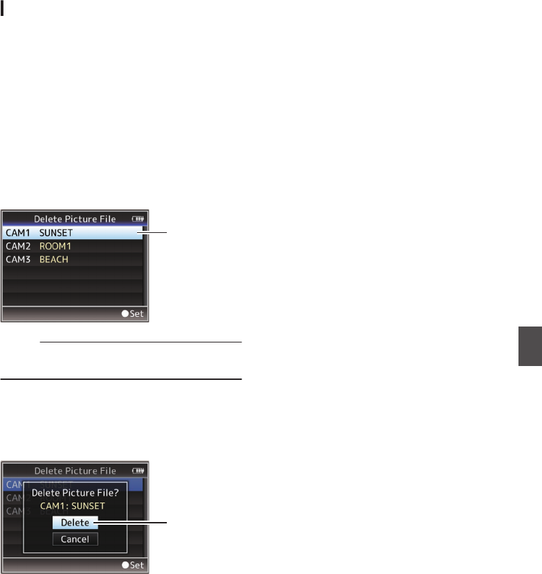
Deleting Setup Files
1Display the [Setup File] menu.
Select [Main Menu] B [System] B [Setup File]
and press the Set button (R).
(A P103 [ Setup File ] )
2Select [Delete File] and press the Set button
(R).
3Select [Picture File], [User File] or [All File],
and press the Set button (R).
The existing files are displayed.
4Select the file to delete using the cross-
shaped button (JK), and press the Set
button (R).
.
4
Memo :
0User File saved on the SD card cannot be
deleted.
5Select [Delete] on the confirmation screen,
and press the Set button (R).
Deletion starts, and “Deleting...” appears on the
screen.
.
5
6Deletion is complete.
After file deletion is complete, “Complete”
appears on the screen.
Configuring Setup Files 123
Camera Features

Loading Clips to the PC
0You can load clips to a PC by connecting the
camera recorder to the PC via the USB port.
Doing so enables clips stored in the SD card to
be managed and edited on the PC.
0Files on the SD card can be managed/edited on
the connected PC in this mode only for USB
mass storage class devices that are recognized
by the said PC as a peripheral drive.
Memo :
0Files cannot be written to the SD card.
1Connect the camera recorder to the PC
using a USB cable.
A confirmation message “Change to USB
Mode?” to enable the USB connection appears.
.
AUX
INPUT2 INPUT1
DEVICE
AV
A
BATT.RELEASE
POWER
/CHG
B
HDMI
REMOTE
DC
REC
AV
DEVICE
PC
2Select [Change] using the cross-shaped
button (JK), and press the Set button (R).
The camera recorder switches to USB mode.
.
2
Memo :
0If recording is in progress, the “Change to USB
Mode?” message appears after recording
stops.
0If playback is in progress, the camera recorder
switches to USB mode after the file closes
automatically, such as when playback stops.
Disconnecting
0Disable the connection on the PC, then remove
the USB cable from the camera recorder.
0Doing so exits the USB mode and switches the
camera recorder to Camera mode.
Memo :
0The procedure for disabling the USB connection
varies according to the PC in use. For details,
refer to the “INSTRUCTIONS” of the PC.
When your PC cannot recognize the SD
card
Confirm and update the OS of your PC.
OS Description
Windows Vista Necessary to update to SP1
or higher.
Windows Vista SP1/
Windows Vista SP2
Necessary to download the
update software.
(KB975823)
032 bit version
http://
www.microsoft.com/
downloads/en/
details.aspx?
FamilyID=2d1abe01-
0942-4f8aabb2-
2ad529de00a1
064 bit version
http://
www.microsoft.com/
downloads/en/
details.aspx?
FamilyID=7d54c53f-017c
-4ea5-
ae08-34c3452ba315
Windows 7 Necessary to download the
update software.
(KB976422)
032 bit version
http://
www.microsoft.com/
downloads/en/
details.aspx?
FamilyID=3ee91fc2-
a9bc-4ee1-
aca3-2a9aff5915ea
064 bit version
http://
www.microsoft.com/
downloads/en/
details.aspx?
FamilyID=73f766dd-
7127-4445-
b860-47084587155f
124 Loading Clips to the PC
Connecting External Devices

Connecting External
Monitor
0
To output live or playback video images and audio
sound to an external monitor, select the output signals
from the camera recorder, and connect using an
appropriate cable according to the monitor to be used.
0
Choose the most suitable terminal according to the
monitor in use.
0
[AV] terminal:
Outputs composite video and audio signals.
0
[HDMI] terminal:
Outputs HDMI signals.
Configure the settings in the [A/V Set] menu to match
the monitor to be connected.
(A P100 [ HDMI out ] )
Memo :
0
If the [HDMI] terminal is connected, configure the
settings in the [A/V Set] menu according to the monitor
to be connected.
(A P100 [ HDMI out ] )
.
AUX
INPUT2 INPUT1
DEVICE
AV
A
BATT.RELEASE
POWER
/CHG
B
HDMI
REMOTE
DC
REC
AV
DEVICE
DC
REMOTE
Audio (Lch)
Audio (Rch)
Video
GND
HDMI
AV input
* Select the output signal in [A/V Set]
B
[HDMI out].
(A P100 [ HDMI out ] )
* To display the menu screen or display screen on an
external monitor, set [A/V Set]
B
[Video Set]
B
[Display On TV] to “On”.
(A P100 [ Display On TV ] )
Setting the Aspect
0
For setting the mode to convert images with a 16:9
aspect ratio to display on a 4:3 aspect ratio screen.
0
Set using [A/V Set]
B
[Video Set]
B
[SD Aspect].
0
The available modes include “Side Cut”, “Letter”
(blackened at the top and bottom), and “Squeeze” (full
size, compressed at the left and right).
(A P105 [ SD Aspect ] )
Memo :
0
When [Record Format]
B
[System] is set to “SD”,
and [SD Aspect] is set to “4:3”, this item cannot be
selected.
(A P105 [ System ] )
(A P105 [ SD Aspect ] )
Connecting External Monitor 125
Connecting External Devices

Connecting the
Headphone
0Audio output from the [x] terminal can be
selected using the [A/V Set] B [Monitor] item or
the [MONITOR] selection switch on the camera
recorder.
(A P103 [ Monitor ] )
0The different combinations of settings that are
output from the [x] terminal and monitor
speaker are as follows.
[MONITOR]
Selection
Switch Setting
[Monitor]
Setting
[x]
Terminal Speaker *
L R
[CH1] - CH1 CH1
[BOTH] [Mix] CH1+CH2 CH1+CH2
[Stereo] CH1 CH2
[CH2] - CH2 CH2
* Audio is output from the speaker only in Media
mode. Does not output in the Camera mode.
.
AUX
INPUT2 INPUT1
DEVICE
AV
A
BATT.RELEASE
POWER
/CHG
B
HDMI
REMOTE
DC
REC
AUX
POWER
/CHG
Memo :
0If both CH1 and CH2 are set to built-in
microphone and the [MONITOR] selection
switch has been set to “BOTH”, stereo sound is
output from the [x] terminal regardless of the
[Monitor] setting.
Connecting Wired Remote
Control
You can operate the functions of this unit with a
wired remote control.
Memo :
0When the switches of the camera recorder and
remote control unit are operated at the same
time, the switch operation of the remote control
unit takes priority over that of the camera
recorder.
1Connect a wired remote control to the
camera recorder.
Connect the wired remote control (sold
separately) to the [REMOTE] terminal of this
camera recorder.
.
AUX
INPUT2 INPUT1
DEVICE
AV
A
BATT.RELEASE
POWER
/CHG
B
HDMI
REMOTE
DC
REC
REMOTE
Connect the wired
remote control
Caution :
0Turn off the power of the camera recorder when
connecting a wired remote control.
2Turn on the power of the camera recorder.
126 Connecting the Headphone
Connecting External Devices

Error Messages and Actions
Warning display on the LCD monitor and viewfinder screen, tally lamp indication and warning tone are as
follows according to the error status.
Memo :
0This camera recorder makes use of a microcomputer. Noise interference from external sources may
prevent it from functioning properly. When this occurs, turn off and on the power of the camera recorder
again.
Error Message Status Action
Turn Power Off Turn Back On
Later
System error.
* The warning tone sounds and
the tally lamp blinks twice every
second.
Turn off the power, and turn it on
again.
If the error persists, please contact
the local dealers in your area.
Getting Overheated. Please
Turn Power Off.
0The battery has exceeded the
specified temperature.
0The power turns off
automatically after about 15
second.
0Wait until the temperature drops
or replace the battery.
0If the error persists, please
contact the local dealers in your
area.
Rec Inhibited [REC] button is pressed when the
write-protect switch of the SD card
is set.
Turn off the write-protect switch of
the SD card, or insert a recordable
SD card.
(A P35 [SD Card] )
Lost Media Info * 0Card is removed while recording
is in progress.
0Card is removed while
formatting is in progress.
0Card is removed while restoring
is in progress.
0Card is removed while adding
the OK mark.
0Card is removed while writing a
setup file.
0Card is removed while deleting a
clip.
(*: A, B)
Restore the card using this camera
recorder.
(A P38 [Restoring the SD Card] )
Record Format Incorrect 0Video format of the file for Clip
Review is different from the
[Frame & Bit Rate] setting of the
camera recorder.
Set [Resolution] and [Frame & Bit
Rate] correctly.
(A P105 [ Resolution ] )
(A P105 [ Frame & Bit Rate ] )
Media Full 0[REC] button is pressed when
the media in use has no
remaining space.
0Remaining space ran out during
recording.
Replace the SD card with a new
one.
Error Messages and Actions 127
Others

Error Message Status Action
No Clips No viewable clips are found on the
card for Clip Review.
Insert an SD card that contains clips
that can be reviewed.
(A P35 [SD Card] )
(A P66 [Viewing Recorded
Videos Immediately (Clip
Review)] )
No Media [REC] button is pressed when an SD
card is not inserted.
Insert an SD card.
(A P35 [SD Card] )
No Media No SD card is found in Media mode
or when the thumbnail screen is
displayed.
Insert an SD card.
(A P35 [SD Card] )
No Clips No clips are found on the inserted
SD card in Media mode or when the
thumbnail screen is displayed.
Insert an SD card that contains
playable clips.
(A P35 [SD Card] )
(A P76 [Playing Recorded
Clips] )
12h Continuation Record The continuous recording time in
AVCHD mode exceeds 12 hours
and recording stops automatically.
To continue recording, press the
[REC] button again.
Blinking of the Tally Lamp
The tally lamp start blinking when the remaining space on the SD card is running out during recording, or
when the battery power is running low.
Blinking Mode Remaining Battery Power/SD Card Space
Blinks slowly
(once every second)
0Battery power is low
0Remaining recording time on SD card is less than 3 minutes (during
recording)
Blinks quickly
(2 times per second)
0Remaining battery power is almost zero
0Remaining recording time on SD card is zero (during recording)
0Error on the camera recorder
Warning Tone
0Warning tone is output from the monitor speaker and [x] terminal when the battery level is low.
Warning tone is also output when an error occurs in the camera recorder.
Memo :
0You can specify whether to turn on the warning tone as well as setting the volume in [A/V Set] B [Audio
Set] B [Alarm Level].
(A P103 [ Alarm Level ] )
128 Error Messages and Actions
Others

Troubleshooting
Symptom Action
Power does not turn on. 0Is the AC adapter properly connected?
0Is the battery charged?
0Is the power turned on immediately after it is turned off?
Make sure to wait for an interval of at least 5 seconds before turning
on the power again.
Unable to start recording. 0Is the record trigger button/lock switch on the handle turned on?
0Is the write-protect switch of the SD card turned on?
Make sure that the write-protect switch is turned off.
(A P35 [Write-Protect Switch on the SD Card] )
0Is the camera recorder set to the Camera mode?
Use the [MODE] selection button to switch to the Camera mode.
(A P14 [Operation Modes] )
0Is the SD card inserted compatible with the recording format?
(A P42 [Selecting a Video Format] )
(A P107 [ 4GB File Spanning(SDXC) ] )
Camera image is not output on
the LCD monitor and
viewfinder screen.
0Is the camera recorder set to the Camera mode?
Use the [MODE] selection button to switch to the Camera mode.
(A P14 [Operation Modes] )
Playback does not start after
selecting a clip thumbnail and
pressing the Set button (R).
0Is the selected clip a playable clip?
Playback is not possible if the clip has a different video format setting.
Images on the LCD monitor
and viewfinder screen appear
dark or blurred.
0Readjust the brightness of the LCD monitor and viewfinder.
0Is the iris closed?
0Is the shutter speed setting too high?
0Is the amount of peaking too little? Use the [PEAKING +/-] button to
adjust the contour for the LCD monitor and the viewfinder screen.
(A P32 [Adjusting the LCD Monitor] )
(A P33 [Adjusting the Viewfinder] )
The [CH1/CH2] recording level
adjustment knob does not
work.
0Is the [CH1/CH2 AUTO/MANUAL] switch set to “AUTO”?
0Is the [FULL AUTO ON/OFF] switch set to “ON”?
Is the [FULL AUTO ON/OFF] switch set to “ON”, and [A/V Set] B
[Audio Set] B [Audio On FULL AUTO] set to “Auto”?
(A P103 [ Audio On FULL AUTO ] )
SD card cannot be initialized
(formatted).
0Is the write-protect switch of the SD card turned on?
Make sure that the write-protect switch is turned off.
(A P35 [Write-Protect Switch on the SD Card] )
Battery alarm appears even
after loading a charged
battery.
0Is the battery too old?
Troubleshooting 129
Others

Symptom Action
The time code and user’s bit
are not displayed.
0Even in Camera mode or Media mode, the time code and user’s bit
may not be displayed depending to the type of display.
0Is [LCD/VF] B [Display Settings] B [TC/UB] set to “Off”? To display
the time code or user’s bit, set it to “TC” or “UB”.
(A P98 [ TC/UB ] )
The date and time are not
displayed.
0The date and time are only displayed on the Display 1 and Display 2
screens in the Camera mode (during shooting).
(A P112 [Display Screen in Camera Mode] )
0Is [System] B [Record Set] B [Time Stamp] set to “On”? To display
the date and time, set it to “Off”.
(A P107 [ Time Stamp ] )
Incorrect display on the
viewfinder.
0
Is the LCD monitor used with [LCD/VF]
B
[LCD + VF] set to “Off”?
(A P96 [ LCD + VF ] )
The actual recording time is
shorter than the estimated
time.
0The recordable time may be shorter depending on the shooting
conditions or the subject.
The two camera recorders are
not synchronized even though
the time codes have been
synchronized. (Z on the Slave
device is not displayed.)
0Is the [TC IN/OUT] switch correctly set?
(A P64 [Synchronizing Time Code on Another Camera] )
0Set [System] B [Record Set] B [Record Format] B [Frame & Bit
Rate] such that the two camera recorders have the same frame rate.
(A P105 [ Frame & Bit Rate ] )
130 Troubleshooting
Others

Specifications
General
Item Description
Power DC 12 V
Power
consumption
Approx. 6 W
(When recording in the factory
default settings using the
viewfinder.)
Mass Approx. 1.9 kg (with battery)
Allowable
operating
temperature
0 °C to 40 °C
Allowable
operating
humidity
30 %RH to 80 %RH
Allowable
storage
temperature
-20 °C to 50 °C
Dimensions (W
× H × D)
177.5 mm × 197 mm × 416 mm
Terminal Section
Item Description
[HDMI] output
terminal (Type A)
V1.4-compliant
[INPUT1/INPUT2] terminal
[MIC] -50 dBu, 3 kK, XLR (balanced),
+48 V output (phantom power
supply)
[LINE] +4 dBu, 10 kK, XLR (balanced)
[AUX] terminal -22 dBu, 10 kK, 3.5 mm stereo
mini jack (unbalanced)
[AV] terminal Φ3.5 mm 4-pin mini jack
Video signal 1.0 V (p-p)
Audio signal -8 dBu (during reference level
input), 1 kK (unbalanced)
[x] terminal Φ3.5 mm mini jack (stereo)
[REMOTE]
terminal
Φ2.5 mm mini jack (stereo)
[U] terminal
[DEVICE] Mini USB-B type, USB 2.0,
slave function (mass storage
class) only
[TC] terminal
[IN] 1.0 V (p-p) to 4.0 V (p-p) high
impedance
[OUT] 2.0 ± 1.0 V (p-p) low impedance
[DC] terminal DC jack (for the supplied AC
adapter)
Lens Section
Item Description
Lens F1.2, f=3.76 mm to 37.6 mm
(Conversion to 35 mm camera
format: f = 29.9 mm to 586 mm:
dynamic zoom)
Filter diameter Φ46 mm
Camera Section
Item Description
Image pickup
device
1/2.3-inch Progressive CMOS
Gain 0dB, 3dB, 6dB, 9dB, 12dB,
15dB, 18dB, 21dB, 24dB, Lolux,
AGC
Electronic
shutter
1/6.25 to 1/10000, EEI
LCD monitor 3.5-inch LCD, 16:9, 920K pixels
Viewfinder 0.24-inch LCOS, 16:9, 1.56M
pixels
Storage Section
Item Description
Supported
media
SDHC/SDXC
Slots x 2
Specifications 131
Others

Video/Audio
Item Description
Recording time Approx. 25 minutes (8 GB SD
card, 35 Mbps, VBR mode)
HD mode (MOV/MP4: MPEG-2)
Video
recording file
format
QuickTime File Format (For
Final Cut Pro)/MP4 File Format
Video
HQ mode MPEG-2 Long GOP VBR, 35
Mbps (Max) MP@HL,
1920x1080/59.94i, 50i
1440x1080/59.94i, 50i
1280x720/59.94p, 50p
SP mode MPEG-2 Long GOP CBR 25
Mbps MP@H14
1440x1080/59.94i, 50i
Audio LPCM 2ch, 48 kHz/16 Bit
HD mode (AVCHD)
Recording file
format
AVCHD File Format
Video MPEG-4 AVC/H.264
Audio Dolby Digital 2ch, 48 kHz/16 Bit,
256 kbps
HQ Mode
(Progressive)
1920x1080/59.94p, 50p
28 Mbps (Max)
HQ mode 1920x1080/59.94i, 50i
24 Mbps (Max)
SP mode 1920x1080/59.94i, 50i
18 Mbps (Max)
LP mode 1440x1080/59.94i, 50i
9 Mbps
EP mode 1440x1080/59.94i, 50i
5 Mbps
HD mode (MOV: H.264)
Video
recording file
format
QuickTime File Format
Video
XHQ Mode
MPEG-4 AVC/H.264, 50 Mbps (Max)
1920×1080/59.94p, 59.94i, 50p, 50i
UHQ Mode
MPEG-4 AVC/H.264, 35 Mbps (Max)
1920x1080/59.94i, 50i
Audio LPCM 2ch, 48 kHz/16 Bit
Item Description
SD mode (MOV: H.264)
Video
recording file
format
QuickTime File Format
Video MPEG-4 AVC/H.264, 8 Mbps
720x576/50i
Audio LPCM 2ch, 48 kHz/16 Bit
Accessories
Accessories
INSTRUCTIONS (BASIC) 1
AC Adapter 1
Power Cord 2
Battery 1
132 Specifications
Others
Produktspezifikationen
| Marke: | JVC |
| Kategorie: | Camcorder |
| Modell: | JY-HM360E |
Brauchst du Hilfe?
Wenn Sie Hilfe mit JVC JY-HM360E benötigen, stellen Sie unten eine Frage und andere Benutzer werden Ihnen antworten
Bedienungsanleitung Camcorder JVC

17 September 2024
31 August 2024
25 August 2024
25 August 2024
23 August 2024
22 August 2024
20 August 2024
14 August 2024
13 August 2024
9 August 2024
Bedienungsanleitung Camcorder
- Camcorder Samsung
- Camcorder 3M
- Camcorder Sanyo
- Camcorder BenQ
- Camcorder Gembird
- Camcorder Genius
- Camcorder Hama
- Camcorder HP
- Camcorder Lexibook
- Camcorder Macally
- Camcorder Medion
- Camcorder Nedis
- Camcorder Philips
- Camcorder SilverCrest
- Camcorder Sony
- Camcorder T'nB
- Camcorder Trust
- Camcorder Panasonic
- Camcorder OK
- Camcorder Canon
- Camcorder Linksys
- Camcorder Maginon
- Camcorder Bresser
- Camcorder Denver
- Camcorder Intenso
- Camcorder König
- Camcorder National Geographic
- Camcorder Renkforce
- Camcorder Trevi
- Camcorder Braun
- Camcorder Kenwood
- Camcorder Sharp
- Camcorder Pyle
- Camcorder Salora
- Camcorder Aiptek
- Camcorder Coby
- Camcorder Lenco
- Camcorder Mpman
- Camcorder Nilox
- Camcorder Polaroid
- Camcorder Jay-Tech
- Camcorder Xiaomi
- Camcorder Hitachi
- Camcorder Hyundai
- Camcorder Toshiba
- Camcorder Olympus
- Camcorder Zoom
- Camcorder Garmin
- Camcorder GOCLEVER
- Camcorder Lamax
- Camcorder Prixton
- Camcorder Mio
- Camcorder Sencor
- Camcorder ViewSonic
- Camcorder Marshall
- Camcorder Nikkei
- Camcorder Samson
- Camcorder SBS
- Camcorder Fujifilm
- Camcorder MINOX
- Camcorder Nikon
- Camcorder Ricoh
- Camcorder DJI
- Camcorder Dragon Touch
- Camcorder EnVivo
- Camcorder Midland
- Camcorder Vtech
- Camcorder Kodak
- Camcorder Agfa
- Camcorder Easypix
- Camcorder Konica-Minolta
- Camcorder Leica
- Camcorder Minolta
- Camcorder Praktica
- Camcorder Rollei
- Camcorder SeaLife
- Camcorder Traveler
- Camcorder IGet
- Camcorder Contax
- Camcorder Mamiya
- Camcorder Voigtländer
- Camcorder Yashica
- Camcorder Bauer
- Camcorder Overmax
- Camcorder Airis
- Camcorder Akaso
- Camcorder Uniden
- Camcorder Kitvision
- Camcorder Kogan
- Camcorder Elmo
- Camcorder Energy Sistem
- Camcorder Jobo
- Camcorder Soundmaster
- Camcorder Bolex
- Camcorder Magellan
- Camcorder TomTom
- Camcorder Kyocera
- Camcorder Cobra
- Camcorder AEE
- Camcorder CamOne
- Camcorder Contour
- Camcorder EVOLVEO
- Camcorder GoPro
- Camcorder Quintezz
- Camcorder ION
- Camcorder DNT
- Camcorder Insignia
- Camcorder Swann
- Camcorder DataVideo
- Camcorder Aida
- Camcorder Prestigio
- Camcorder Mediacom
- Camcorder Tracer
- Camcorder Cisco
- Camcorder RCA
- Camcorder ARRI
- Camcorder Transcend
- Camcorder Oregon Scientific
- Camcorder Blackmagic Design
- Camcorder Insta360
- Camcorder Zorki
- Camcorder DOD
- Camcorder Drift
- Camcorder Ematic
- Camcorder FHD 1080P
- Camcorder Flip
- Camcorder ISAW
- Camcorder Leotec
- Camcorder MMTC
- Camcorder Mobius
- Camcorder Naxa
- Camcorder Replay
- Camcorder Sakar
- Camcorder SJCAM
- Camcorder Spypoint
- Camcorder Storex
- Camcorder TacTic
- Camcorder Veho
- Camcorder Vivitar
- Camcorder YI
- Camcorder Zagg
- Camcorder Best Buy
- Camcorder AgfaPhoto
- Camcorder Vupoint Solutions
- Camcorder Kaiser Baas
- Camcorder Microtek
- Camcorder Runcam
- Camcorder Activeon
- Camcorder BlackVue
- Camcorder Braun Phototechnik
- Camcorder Hamlet
- Camcorder RSC
- Camcorder Kobian
- Camcorder Hamilton Buhl
- Camcorder Contour Design
- Camcorder Curve
- Camcorder Beaulieu
- Camcorder Qoltec
- Camcorder Stealth Cam
- Camcorder DXG
- Camcorder GoXtreme
- Camcorder ATN
- Camcorder Whistler
- Camcorder Aqua-Vu
Neueste Bedienungsanleitung für -Kategorien-

25 November 2024
25 November 2024
24 November 2024
12 Oktober 2024

12 Oktober 2024

8 Oktober 2024

7 Oktober 2024
3 Oktober 2024
28 September 2024
24 September 2024