HP EliteDesk 705 G2 Bedienungsanleitung
Lesen Sie kostenlos die 📖 deutsche Bedienungsanleitung für HP EliteDesk 705 G2 (153 Seiten) in der Kategorie Desktop. Dieser Bedienungsanleitung war für 12 Personen hilfreich und wurde von 2 Benutzern mit durchschnittlich 4.5 Sternen bewertet
Seite 1/153

Maintenance and Service Guide
HP EliteDesk 705 G2 Small Form Factor

© Copyright 2015 HP Development Company,
L.P.
AMD is a trademark of Advanced Micro Devices,
Inc. Bluetooth is a trademark owned by its
proprietor and used by Hewlett-Packard
Company under license. Intel, Celeron, and
Pentium are trademarks of Intel Corporation in
the U.S. and other countries. Microsoft and
Windows are trademarks of the Microsoft
group of companies.
The information contained herein is subject to
change without notice. The only warranties for
HP products and services are set forth in the
express warranty statements accompanying
such products and services. Nothing herein
should be construed as constituting an
additional warranty. HP shall not be liable for
technical or editorial errors or omissions
contained herein.
First Edition (September 2015)
Document Part Number: 822866-001
Product notice
This user guide describes features that are
common to most models. Some features may
not be available on your computer.
Not all features are available in all editions of
Windows. This computer may require upgraded
and/or separately purchased hardware, drivers
and/or software to take full advantage of
Windows functionality. Go to
http://www.microsoft.com for details.
Software terms
By installing, copying, downloading, or
otherwise using any software product
preinstalled on this computer, you agree to be
bound by the terms of the HP End User License
Agreement (EULA). If you do not accept these
license terms, your sole remedy is to return the
entire unused product (hardware and software)
within 14 days for a full refund subject to the
refund policy of your seller.
For any further information or to request a full
refund of the price of the computer, please
contact your seller.

Safety warning notice
WARNING! To reduce the possibility of heat-related injuries or of overheating the device, do not place
the device directly on your lap or obstruct the device air vents. Use the device only on a hard, surface. Do at
not allow another hard surface, such as an adjoining optional printer, or a soft surface, such as pillows or rugs
or clothing, to block Also, do not allow the AC adapter to contact the skin or a soft surface, such as airow.
pillows or rugs or clothing, during operation. The device and the AC adapter comply with the user-accessible
surface temperature limits by the International Standard for Safety of Information Technology dened
Equipment (IEC 60950).
iii

iv Safety warning notice

Table of contents
1 Product features ........................................................................................................................................... 1
Standard features ........................................................................................................................... 1conguration
Front panel components ........................................................................................................................................ 2
Rear panel components ......................................................................................................................................... 3
Serial number location .......................................................................................................................................... 4
2 Illustrated parts catalog ................................................................................................................................ 5
Small Form Factor (SFF) chassis spare parts ........................................................................................................ 5
Computer major components ............................................................................................................. 5
Misc parts ............................................................................................................................................. 7
Drives ................................................................................................................................................... 9
3 Routine care, SATA drive guidelines, and disassembly preparation .................................................................. 11
Electrostatic discharge information .................................................................................................................... 11
Generating static ............................................................................................................................... 11
Preventing electrostatic damage to equipment ............................................................................... 12
Personal grounding methods and equipment .................................................................................. 12
Grounding the work area ................................................................................................................... 12
Recommended materials and equipment ........................................................................................ 13
Operating guidelines ........................................................................................................................................... 13
Routine care ......................................................................................................................................................... 14
General cleaning safety precautions ................................................................................................ 14
Cleaning the Computer Case ............................................................................................................. 14
Cleaning the keyboard ....................................................................................................................... 14
Cleaning the monitor ......................................................................................................................... 15
Cleaning the mouse ........................................................................................................................... 15
Service considerations ......................................................................................................................................... 15
Power supply fan ............................................................................................................................... 15
Tools and software Requirements .................................................................................................... 15
Screws ............................................................................................................................................... 16
Cables and connectors ...................................................................................................................... 16
Hard Drives ........................................................................................................................................ 16
Lithium coin cell battery .................................................................................................................... 16
SATA hard drives .................................................................................................................................................. 17
SATA hard drive cables ......................................................................................................................................... 17
SATA data cable ................................................................................................................................. 17
v

SMART ATA drives ................................................................................................................................................ 17
Cable management .............................................................................................................................................. 18
4 Removal and replacement procedures – small form factor (SFF) chassis .......................................................... 19
Preparation for disassembly ............................................................................................................................... 19
Access panel ......................................................................................................................................................... 20
Front bezel ........................................................................................................................................................... 20
Front bezel security ............................................................................................................................................. 21
Slim optical drive bezel blank .............................................................................................................................. 22
Memory ................................................................................................................................................................ 23
DIMMs ................................................................................................................................................ 23
DDR3/DDR3L-SDRAM DIMMs ............................................................................................................. 23
Populating DIMM sockets .................................................................................................................. 23
Installing DIMMs ................................................................................................................................ 24
Expansion card ..................................................................................................................................................... 26
Drives ................................................................................................................................................................... 30
System board connections ................................................................................................................ 31
Drive positions ................................................................................................................................... 32
Installing and Removing Drives ........................................................................................................ 32
Removing a 9.5mm slim optical drive ............................................................................ 34
Installing a 9.5mm slim optical drive ............................................................................. 35
Removing and replacing a primary 3.5-inch hard drive ................................................. 36
Removing a secondary 3.5-inch hard drive .................................................................... 39
Installing a secondary 3.5-inch hard drive ..................................................................... 40
Removing a 2.5-inch hard drive ...................................................................................... 42
Installing a 2.5-inch hard drive ....................................................................................... 43
Drive power cable ................................................................................................................................................ 46
Small .......................................................................................................................................................... 47bae
Fan ............................................................................................................................................................. 48bae
Hood lock ............................................................................................................................................................. 49
Front I/O assembly ............................................................................................................................................... 51
Power switch ........................................................................................................................................................ 53
Speaker ................................................................................................................................................................ 54
Fan sink ................................................................................................................................................................ 55
Processor ............................................................................................................................................................. 56
Power supply ....................................................................................................................................................... 58
System board ....................................................................................................................................................... 60
System board callouts ....................................................................................................................... 61
Using the Small Form Factor Computer in a Tower Orientation ......................................................................... 62
vi

5 Computer Setup (F10) Utility ........................................................................................................................ 63
Computer Setup (F10) Utilities ............................................................................................................................ 63
Using Computer Setup (F10) Utilities ................................................................................................ 63
Computer Setup–Main ....................................................................................................................... 65
Computer Setup—Security ............................................................................................................... 67
Computer Setup—Advanced ............................................................................................................. 69
Recovering the Settings ............................................................................................................... 73Conguration
6 Troubleshooting without diagnostics ............................................................................................................ 74
Safety and comfort .............................................................................................................................................. 74
Before you call for technical support .................................................................................................................. 74
Helpful hints ........................................................................................................................................................ 75
Solving general problems .................................................................................................................................... 76
Solving power problems ...................................................................................................................................... 80
Solving hard drive problems ................................................................................................................................ 81
Solving media card reader problems ................................................................................................................... 83
Solving display problems .................................................................................................................................... 84
Solving audio problems ....................................................................................................................................... 89
Solving printer problems ..................................................................................................................................... 91
Solving keyboard and mouse problems .............................................................................................................. 92
Solving Hardware Installation Problems ............................................................................................................. 94
Solving Network Problems .................................................................................................................................. 95
Solving memory problems .................................................................................................................................. 98
Solving CD-ROM and DVD problems .................................................................................................................. 100
Solving USB drive problems ..................................................................................................................... 102ash
Solving front panel component problems ........................................................................................................ 103
Solving Internet access problems ..................................................................................................................... 103
Solving software problems ............................................................................................................................... 105
7 POST error messages and diagnostic front panel LEDs and audible codes ....................................................... 106
POST numeric codes and text messages .......................................................................................................... 106
Interpreting system validation diagnostic front panel LEDs and audible codes .............................................. 111
8 Password security and resetting CMOS ........................................................................................................ 113
Resetting the password jumper ........................................................................................................................ 113
Changing a Setup or Power-On password ......................................................................................................... 114
Deleting a Setup or Power-On password .......................................................................................................... 115
Clearing and resetting the CMOS ....................................................................................................................... 115
vii

9 HP PC Hardware Diagnostics ....................................................................................................................... 117
Why run HP PC Hardware Diagnostics ............................................................................................................... 117
How to access and run HP PC Hardware Diagnostics ........................................................................................ 117
Downloading HP PC Hardware Diagnostics (UEFI) to a USB device .................................................................. 117
10 System backup and recovery ..................................................................................................................... 119
Backing up, restoring, and recovering in Windows 10 ...................................................................................... 119
Creating recovery media and backups ............................................................................................ 119
Creating HP Recovery media (select products only) .................................................... 119
Using Windows tools ....................................................................................................................... 121
Restore and recovery ...................................................................................................................... 121
Recovering using HP Recovery Manager ...................................................................... 121
What you need to know before you get started ........................................ 121
Using the HP Recovery partition (select products only) ............................ 122
Using HP Recovery media to recover ......................................................... 122
Changing the computer boot order ............................................................ 123
Removing the HP Recovery partition (select products only) ..................... 123
Backing up, restoring, and recovering in Windows 8.1 or Windows 8 .............................................................. 123
Creating recovery media and backups ............................................................................................ 123
Restoring and recovering using Windows tools ............................................................................. 124
Using Reset when the system is not responding ......................................................... 124
Recovery using the Windows recovery USB drive ............................................... 125ash
Recovery using Windows operating system media (purchased separately) ............... 125
Backing up, restoring, and recovering in Windows 7 ........................................................................................ 125
Creating recovery media ................................................................................................................. 126
Creating recovery media using HP Recovery Manager (select models only) ............... 126
Creating recovery discs with HP Recovery Disc Creator (select models only) ............. 127
Creating recovery discs .............................................................................. 128
Backing up your information ........................................................................................ 128
System Restore ............................................................................................................................... 129
System Recovery ............................................................................................................................. 129
System Recovery when Windows is responding .......................................................... 129
System Recovery when Windows is not responding .................................................... 130
System Recovery using recovery media (select models only) ..................................... 130
Using HP Recovery Disc operating system discs (select models only) ........................ 131
Appendix A Battery replacement ................................................................................................................... 133
Appendix B Power Cord Set Requirements ...................................................................................................... 136
General Requirements ....................................................................................................................................... 136
viii

Japanese Power Cord Requirements ................................................................................................................. 136
Country-Specic Requirements ........................................................................................................................ 137
Appendix C Statement of Volatility ................................................................................................................ 138
Appendix D ............................................................................................................................. 140Specications
SFF .............................................................................................................................................. 140Specications
Index ........................................................................................................................................................... 141
ix

x

1 Product features
Standard featuresconguration
Features may vary depending on the model. For support assistance and to learn more about the hardware
and software installed on your computer model, run the HP Support Assistant utility.
NOTE: This computer model can be used in a tower orientation or a desktop orientation.
Standard features 1conguration

Front panel components
Drive may vary by model. Some models have a bezel blank covering the slim optical drive bay.conguration
1 Slim Optical Drive (optional) 6 Headphone Connector
2 USB 2.0 Charging (powered) Port (black) 7 Dual-State Power Button
3 USB 2.0 Port (black) 8 Hard Drive Activity Light
4 USB 3.0 Ports (blue) 9 SD Card Reader (optional)
5 Microphone/Headphone Connector
NOTE: When a device is plugged into the Microphone/Headphone Connector, a dialog box will pop up asking if you want to
use the connector for a microphone line-In device or a headphone. You can the connector at any time by recongure
double-clicking the Audio Manager icon in the Windows taskbar.
NOTE: The USB 2.0 Charging Port also provides current to charge a device such as a Smart Phone. The charging current is
available whenever the power cord is plugged into the system, even when the system is o.
NOTE: The Power On Light is normally white when the power is on. If it is red, there is a problem with the ashing
computer and it is displaying a diagnostic code.
2 Chapter 1 Product features

Rear panel components
1 PS/2 Mouse Connector (green) 7 PS/2 Keyboard Connector (purple)
2 Serial Connector 8 DisplayPort Monitor Connectors
3 RJ-45 Network Connector 9 VGA Monitor Connector
4 USB 2.0 Ports with Wake from S4 feature (black) 10 USB 3.0 Ports (blue)
5 Line-In Audio Connector (blue) 11 USB 2.0 Ports (black)
6 Power Cord Connector 12 Line-Out Connector for powered audio
devices (green)
NOTE: An optional second serial port and an optional parallel port are available from HP.
If using a USB keyboard, HP recommends connecting the keyboard to one of the USB 2.0 ports with the wake from S4 feature.
The wake from S4 feature is also supported on the PS/2 connectors if enabled in BIOS F10 Setup.
When a device is plugged into the blue Line-In Audio Connector, a dialog box will pop up asking if you want to use the
connector for a line-in device or a microphone. You can the connector at any time by double-clicking the Audio recongure
Manager icon in the Windows taskbar.
When a graphics card is installed in one of the system board slots, the video connectors on the graphics card and the
integrated graphics on the system board may be used at the same time. However, for such a only the display conguration,
connected to the discrete graphics card will display POST messages.
The system board graphics can be disabled by changing settings in Computer Setup.
Rear panel components 3

Serial number location
Each computer has a unique serial number and a product ID number that are located on the exterior of the
computer. Keep these numbers available for use when contacting customer service for assistance.
4 Chapter 1 Product features

2 Illustrated parts catalog
Small Form Factor (SFF) chassis spare parts
Computer major components
NOTE: HP continually improves and changes product parts. For complete and current information on
supported parts for your computer, go to http://partsurfer.hp.com, select your country or region, and then
follow the on-screen instructions.
Item Description
(1) Access panel
(2) Front bezel
*Bezel blank
(3) System board (includes replacement thermal material)
Small Form Factor (SFF) chassis spare parts 5

Item Description
(4) Power supply
200W, 92% ecient
200W, 85% ecient
200W, standard
(5) Fan sink (includes replacement thermal material)
(PC3-12800, 1600-MHz)Memory modules
8-GB
4-GB
2-GB
(include replacement thermal material)Processors
AMD A10-8850B, 3.9 GHz
AMD A10-8750B, 3.6 GHz
AMD A10-7800B, 3.57 GHz
AMD A8-8650B, 3.2 GHz
AMD A8-7600B, 3.1 GHz
AMD A6-8550B, 3.7 GHz
AMD A6-8350B, 3.5 GHz
AMD A4-7300B, 3.8 GHz
6 Chapter 2 Illustrated parts catalog
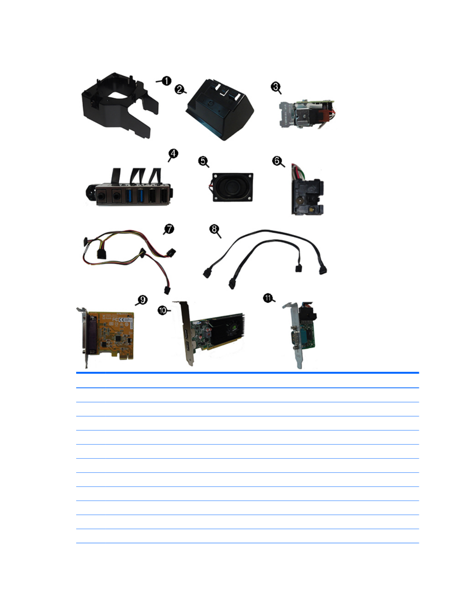
Misc parts
Item Description
(1) Fan bae
(2) Rear bae
(3) Solenoid lock
(4) Front I/O assembly
(5) Speaker
(6) Power switch
(7) SATA drive power cable
(8) SATA data cable, 14 inch, 1 straight end, 1 angled end
(9) Printer port, PCI card
(10) nVIDIA GT730 Grayling 2 GB DDR3 PCIex8
(11) Serial port, PCI card
Small Form Factor (SFF) chassis spare parts 7

Item Description
*Chassis stand
*Center strip kit
*M.2 USB cable
*SATA SS power extension, 20 inch cable
*Slim optical drive bezel blank
* Hard drive conversion bracket, 2.5-inch to 3.5-inch
* Hood sensor
* HP Business PC Security Lock
*Rubber foot
*Secure Digital (SD) card reader
*Keyed cable lock
*Grommet, hard drive isolation, blue
*DisplayPort cable
* USB 3.1 Type Cx1 PCIe p18-x1 card
* PCIe to M.2 adapter
* WLAN module caddy card + Bluetooth
* Wireless antenna for use with WLAN modules
*Adapters
2.5-inch for card reader
DisplayPort to HDMI 1.4
DisplayPort to VGA
DisplayPort to DVI
DVI to VGA
DVI-I to VGA
USB-C to USB 3.0
*Mouse
PS2, optical
USB, laser
USB, optical
Antimicrobial
Washable
Wireless
HP USB Hardened
*Keyboards
8 Chapter 2 Illustrated parts catalog

Item Description
PS/2
PS/2 slim
USB
HP USB slim
HP USB Conferencing
Wireless keyboard, mouse, and dongle
USB/PS2 Washable
Smart card
Drives
Description
Hard drives/Solid-state drives
2-TB, 7200-rpm
1-TB, 7200-rpm, 3.5-inch
1-TB, 7200-rpm, 2.5-inch
1-TB, hybrid SSD, 3.5-inch or 2.5-inch
500-GB, 7200-rpm, 2.5-inch, SED
500 GB, 7200 rpm, 3.5-inch or 2.5-inch
500-GB, 7200-rpm, 2.5-inch, OPAL2, self-encrypting drive (SED)
500-GB, 5400-rpm, 2.5-inch, FIPS
500-GB, hybrid SSD, 2.5-inch or 2.5-inch
500-GB, 5400-rpm, 2.5-inch, 5 mm
512 GB Solid-state Drive (SSD)
512-GB Solid-state Drive (SSD), M.2, 2280SS, PCIe
256-GB Solid-state Drive (SSD), self-encrypting (SED)
256-GB Solid-state Drive (SSD)
256-GB Solid-state Drive (SSD), TLC
256-GB Solid-state Drive (SSD), M.2, 2280SS, PCIe
180 GB Solid-state Drive (SSD)
180 GB Solid-state Drive (SSD), OPAL2, MLC
128-GB Solid-state Drive (SSD), self-encrypting drive (SED)
128-GB Solid-state Drive (SSD)
128-GB Solid-state Drive (SSD), TLC
Small Form Factor (SFF) chassis spare parts 9

Description
128-GB Solid-state Drive (SSD), M.2, 2280SS, PCIe
120-GB Solid-state Drive (SSD)
120-GB Solid-state Drive (SSD), OPAL2, MLC
Optical drives
Blu-ray BD-Writer XL Drive
DVD±RW drive
DVD-ROM drive
Grommet, hard drive isolation, blue
10 Chapter 2 Illustrated parts catalog

3 Routine care, SATA drive guidelines, and
disassembly preparation
This chapter provides general service information for the computer. Adherence to the procedures and
precautions described in this chapter is essential for proper service.
CAUTION: When the computer is plugged into an AC power source, voltage is always applied to the system
board. You must disconnect the power cord from the power source before opening the computer to prevent
system board or component damage.
Electrostatic discharge information
A sudden discharge of static electricity from your or other conductor can destroy static-sensitive nger
devices or microcircuitry. Often the spark is neither felt nor heard, but damage occurs. An electronic device
exposed to electrostatic discharge (ESD) may not appear to be at all and can work perfectly aected
throughout a normal cycle. The device may function normally for a while, but it has been degraded in the
internal layers, reducing its life expectancy.
Networks built into many integrated circuits provide some protection, but in many cases, the discharge
contains enough power to alter device parameters or melt silicon junctions.
Generating static
The following table shows that:
●Dierent activities generate amounts of static electricity.dierent
●Static electricity increases as humidity decreases.
Relative Humidity
Event 55% 40% 10%
Walking across carpet
Walking across vinyl oor
Motions of bench worker
Removing DIPs from plastic tube
7,500 V
3,000 V
400 V
400 V
15,000 V
5,000 V
800 V
700 V
35,000 V
12,000 V
6,000 V
2,000 V
Removing DIPs from vinyl tray
Removing DIPs from Styrofoam
Removing bubble pack from PCB
Packing PCBs in foam-lined box
2,000 V
3,500 V
7,000 V
5,000 V
4,000 V
5,000 V
20,000 V
11,000 V
11,500 V
14,500 V
26,500 V
21,000 V
These are then multi-packaged inside plastic tubes, trays, or Styrofoam.
NOTE: 700 volts can degrade a product.
Electrostatic discharge information 11

Preventing electrostatic damage to equipment
Many electronic components are sensitive to ESD. Circuitry design and structure determine the degree of
sensitivity. The following packaging and grounding precautions are necessary to prevent damage to electric
components and accessories.
●To avoid hand contact, transport products in static-safe containers such as tubes, bags, or boxes.
●Protect all electrostatic parts and assemblies with conductive or approved containers or packaging.
●Keep electrostatic sensitive parts in their containers until they arrive at static-free stations.
●Place items on a grounded surface before removing them from their container.
●Always be properly grounded when touching a sensitive component or assembly.
●Avoid contact with pins, leads, or circuitry.
●Place reusable electrostatic-sensitive parts from assemblies in protective packaging or conductive
foam.
Personal grounding methods and equipment
Use the following equipment to prevent static electricity damage to equipment:
●Wrist straps are straps with a maximum of one-megohm ± 10% resistance in the ground cords. exible
To provide proper ground, a strap must be worn snug against bare skin. The ground cord must be
connected and snugly into the banana plug connector on the grounding mat or workstation.t
●Heel straps/Toe straps/Boot straps can be used at standing workstations and are compatible with
most types of shoes or boots. On conductive or dissipative mats, use them on both feet with oors oor
a maximum of one-megohm ± 10% resistance between the operator and ground.
Static Shielding Protection Levels
Method Voltage
Antistatic plastic
Carbon-loaded plastic
Metallized laminate
1,500
7,500
15,000
Grounding the work area
To prevent static damage at the work area, use the following precautions:
●Cover the work surface with approved static-dissipative material. Provide a wrist strap connected to the
work surface and properly grounded tools and equipment.
●Use static-dissipative mats, foot straps, or air ionizers to give added protection.
●Handle electrostatic sensitive components, parts, and assemblies by the case or PCB laminate. Handle
them only at static-free work areas.
●Turn power and input signals before inserting and removing connectors or test equipment.o
●Use made of static-safe materials when must directly contact dissipative surfaces.xtures xtures
●Keep work area free of nonconductive materials such as ordinary plastic assembly aids and Styrofoam.
●Use service tools, such as cutters, screwdrivers, and vacuums, that are conductive.eld
12 Chapter 3 Routine care, SATA drive guidelines, and disassembly preparation

Recommended materials and equipment
Materials and equipment that are recommended for use in preventing static electricity include:
●Antistatic tape
●Antistatic smocks, aprons, or sleeve protectors
●Conductive bins and other assembly or soldering aids
●Conductive foam
●Conductive tabletop workstations with ground cord of one-megohm +/- 10% resistance
●Static-dissipative table or mats with hard tie to groundoor
●Field service kits
●Static awareness labels
●Wrist straps and footwear straps providing one-megohm +/- 10% resistance
●Material handling packages
●Conductive plastic bags
●Conductive plastic tubes
●Conductive tote boxes
●Opaque shielding bags
●Transparent metallized shielding bags
●Transparent shielding tubes
Operating guidelines
To prevent overheating and to help prolong the life of the computer:
●Keep the computer away from excessive moisture, direct sunlight, and extremes of heat and cold.
●Operate the computer on a sturdy, level surface. Leave a 10.2-cm (4-inch) clearance on all vented sides
of the computer and above the monitor to permit the required airow.
●Never restrict the into the computer by blocking any vents or air intakes. Do not place the airow
keyboard, with the keyboard feet down, directly against the front of the desktop unit as this also
restricts airow.
●Occasionally clean the air vents on all vented sides of the computer. Lint, dust, and other foreign matter
can block the vents and limit the Be sure to unplug the computer before cleaning the air vents.airow.
●Never operate the computer with the cover or side panel removed.
●Do not stack computers on top of each other or place computers so near each other that they are subject
to each other’s re-circulated or preheated air.
●If the computer is to be operated within a separate enclosure, intake and exhaust ventilation must be
provided on the enclosure, and the same operating guidelines listed above will still apply.
●Keep liquids away from the computer and keyboard.
Operating guidelines 13

●Never cover the ventilation slots on the monitor with any type of material.
●Install or enable power management functions of the operating system or other software, including
sleep states.
Routine care
General cleaning safety precautions
1. Never use solvents or ammable solutions to clean the computer.
2. Never immerse any parts in water or cleaning solutions; apply any liquids to a clean cloth and then use
the cloth on the component.
3. Always unplug the computer when cleaning with liquids or damp cloths.
4. Always unplug the computer before cleaning the keyboard, mouse, or air vents.
5. Disconnect the keyboard before cleaning it.
6. Wear safety glasses equipped with side shields when cleaning the keyboard.
Cleaning the Computer Case
Follow all safety precautions in General cleaning safety precautions on page 14 before cleaning the computer.
To clean the computer case, follow the procedures described below:
●To remove light stains or dirt, use plain water with a clean, lint-free cloth or swab.
●For stronger stains, use a mild dishwashing liquid diluted with water. Rinse well by wiping it with a cloth
or swab dampened with clear water.
●For stubborn stains, use isopropyl (rubbing) alcohol. No rinsing is needed as the alcohol will evaporate
quickly and not leave a residue.
●After cleaning, always wipe the unit with a clean, lint-free cloth.
●Occasionally clean the air vents on the computer. Lint and other foreign matter can block the vents and
limit the airow.
Cleaning the keyboard
Follow all safety precautions in General cleaning safety precautions on page 14 before cleaning the keyboard.
To clean the tops of the keys or the keyboard body, follow the procedures described in Cleaning the Computer
Case on page 14.
When cleaning debris from under the keys, review all rules in General cleaning safety precautions on page 14
before following these procedures:
CAUTION: Use safety glasses equipped with side shields before attempting to clean debris from under the
keys.
●Visible debris underneath or between the keys may be removed by vacuuming or shaking.
●Canned, pressurized air may be used to clean debris from under the keys. Caution should be used as too
much air pressure can dislodge lubricants applied under the wide keys.
14 Chapter 3 Routine care, SATA drive guidelines, and disassembly preparation

●If you remove a key, use a specially designed key puller to prevent damage to the keys. This tool is
available through many electronic supply outlets.
CAUTION: Never remove a wide leveled key (like the space bar) from the keyboard. If these keys are
improperly removed or installed, the keyboard may not function properly.
●Cleaning under a key may be done with a swab moistened with isopropyl alcohol and squeezed out. Be
careful not to wipe away lubricants necessary for proper key functions. Use tweezers to remove any
bers conned or dirt in areas. Allow the parts to air dry before reassembly.
Cleaning the monitor
●Wipe the monitor screen with a clean cloth moistened with water or with a towelette designed for
cleaning monitors. Do not use sprays or aerosols directly on the screen; the liquid may seep into the
housing and damage a component. Never use solvents or liquids on the monitor.ammable
●To clean the monitor body follow the procedures in Cleaning the Computer Case on page 14.
Cleaning the mouse
Before cleaning the mouse, ensure that the power to the computer is turned o.
●Clean the mouse ball by removing the retaining plate and the ball from the housing. Pull out any rst
debris from the ball socket and wipe the ball with a clean, dry cloth before reassembly.
●To clean the mouse body, follow the procedures in Cleaning the Computer Case on page 14.
Service considerations
Listed below are some of the considerations that you should keep in mind during the disassembly and
assembly of the computer.
Power supply fan
The power supply fan is a variable-speed fan based on the temperature in the power supply.
CAUTION: The cooling fan is always on when the computer is in the “On” mode. The cooling fan is when o
the computer is in “Standby,” “Suspend,” or modes. “O”
You must disconnect the power cord from the power source before opening the computer to prevent system
board or component damage.
Tools and software Requirements
To service the computer, you need the following:
●Torx T-15 screwdriver
●Torx T-15 screwdriver with small diameter shank (for certain front bezel removal)
●Flat-bladed screwdriver (may sometimes be used in place of the Torx screwdriver)
●Phillips #2 screwdriver
●Diagnostics software
●Tamper-resistant T-15 wrench
Service considerations 15

Screws
The screws used in the computer are not interchangeable. They may have standard or metric threads and may
be of lengths. If an incorrect screw is used during the reassembly process, it can damage the unit. HP dierent
strongly recommends that all screws removed during disassembly be kept with the part that was removed,
then returned to their proper locations.
CAUTION: Metric screws have a black U.S. screws have a silver and are used on hard drives only.nish. nish
CAUTION: As each subassembly is removed from the computer, it should be placed away from the work area
to prevent damage.
Cables and connectors
Most cables used throughout the unit are cables. These cables must be handled with care to at, exible
avoid damage. Apply only the tension required to seat or unseat the cables during insertion or removal from
the connector. Handle cables by the connector whenever possible. In all cases, avoid bending or twisting the
cables, and ensure that the cables are routed in such a way that they cannot be caught or snagged by parts
being removed or replaced.
CAUTION: When servicing this computer, ensure that cables are placed in their proper location during the
reassembly process. Improper cable placement can damage the computer.
Hard Drives
Handle hard drives as delicate, precision components, avoiding all physical shock and vibration. This applies
to failed drives as well as replacement spares.
●If a drive must be mailed, place the drive in a bubble-pack mailer or other suitable protective packaging
and label the package “Fragile: Handle With Care.”
●Do not remove hard drives from the shipping package for storage. Keep hard drives in their protective
packaging until they are actually mounted in the computer.
●Avoid dropping drives from any height onto any surface.
●If you are inserting or removing a hard drive, turn the computer. Do not remove a hard drive while the o
computer is on or in standby mode.
●Before handling a drive, ensure that you are discharged of static electricity. While handling a drive, avoid
touching the connector.
●Do not use excessive force when inserting a drive.
●Avoid exposing a hard drive to liquids, temperature extremes, or products that have magnetic elds
such as monitors or speakers.
Lithium coin cell battery
The battery that comes with the computer provides power to the real-time clock and has a minimum lifetime
of about three years.
See the appropriate removal and replacement chapter for the chassis you are working on in this guide for
instructions on the replacement procedures.
WARNING! This computer contains a lithium battery. There is a risk of and chemical burn if the battery is re
handled improperly. Do not disassemble, crush, puncture, short external contacts, dispose in water or or re,
expose it to temperatures higher than 140ºF (60ºC). Do not attempt to recharge the battery.
16 Chapter 3 Routine care, SATA drive guidelines, and disassembly preparation

NOTE: Batteries, battery packs, and accumulators should not be disposed of together with the general
household waste. In order to forward them to recycling or proper disposal, please use the public collection
system or return them to HP, their authorized partners, or their agents.
SATA hard drives
Serial ATA Hard Drive Characteristics
Number of pins/conductors in data cable 7/7
Number of pins in power cable 15
Maximum data cable length 39.37 in (100 cm)
Data interface voltage 400-700 mVdierential
Drive voltages 3.3 V, 5 V, 12 V
Jumpers for drive N/Aconguring
Data transfer rate 6.0 Gb/s
SATA hard drive cables
SATA data cable
Always use an HP approved SATA 6.0 Gb/s cable as it is fully backwards compatible with the SATA 1.5 Gb/s
drives.
Current HP desktop products ship with SATA 6.0 Gb/s hard drives.
SATA data cables are susceptible to damage if Never crease a SATA data cable and never bend it overexed.
tighter than a 30 mm (1.18 in) radius.
The SATA data cable is a thin, 7-pin cable designed to transmit data for only a single drive.
SMART ATA drives
The Self Monitoring Analysis and Recording Technology (SMART) ATA drives for the HP Personal Computers
have built-in drive failure prediction that warns the user or network administrator of an impending failure or
crash of the hard drive. The SMART drive tracks fault prediction and failure indication parameters such as
reallocated sector count, spin retry count, and calibration retry count. If the drive determines that a failure is
imminent, it generates a fault alert.
SATA hard drives 17

Cable management
Always follow good cable management practices when working inside the computer.
●Keep cables away from major heat sources like the heat sink.
●Do not jam cables on top of expansion cards or memory modules. Printed circuit cards like these are not
designed to take excessive pressure on them.
●Keep cables clear of sliding or moveable parts to prevent them from being cut or crimped when the parts
are moved.
●When folding a ribbon cable, never fold to a sharp crease. Sharp creases may damage the wires.at
●Some ribbon cables come prefolded. Never change the folds on these cables.at
●Do not bend any cable sharply. A sharp bend can break the internal wires.
●Never bend a SATA data cable tighter than a 30 mm (1.18 in) radius.
●Never crease a SATA data cable.
●Do not rely on components like the drive cage, power supply, or computer cover to push cables down
into the chassis. Always position the cables to lay properly by themselves.
18 Chapter 3 Routine care, SATA drive guidelines, and disassembly preparation

4 Removal and replacement procedures –
small form factor (SFF) chassis
Adherence to the procedures and precautions described in this chapter is essential for proper service. After
completing all necessary removal and replacement procedures, run the Diagnostics utility to verify that all
components operate properly.
NOTE: Not all features listed in this guide are available on all computers.
Preparation for disassembly
See Routine care, SATA drive guidelines, and disassembly preparation on page 11 for initial safety procedures.
1. Remove/disengage any security devices that prohibit opening the computer.
2. Close any open software applications.
3. Exit the operating system.
4. Remove any compact disc or media card from the computer.
5. Turn the computer and any peripheral devices that are connected to it.o
CAUTION: Turn the computer before disconnecting any cables.o
Regardless of the power-on state, voltage is always present on the system board as long as the system
is plugged into an active AC outlet. In some systems the cooling fan is on even when the computer is in
the “Standby,” or “Suspend” modes. The power cord should always be disconnected before servicing a
unit.
6. Disconnect the power cord from the electrical outlet and then from the computer.
7. Disconnect all peripheral device cables from the computer.
NOTE: During disassembly, label each cable as you remove it, noting its position and routing. Keep all
screws with the units removed.
CAUTION: The screws used in the computer are of thread sizes and lengths; using the wrong dierent
screw in an application may damage the unit.
8. If the computer is on a stand, remove the computer from the stand.
Preparation for disassembly 19

Access panel
1. Prepare the computer for disassembly (Preparation for disassembly on page 19).
2. Pull up the access panel handle (1), and then lift the panel the computer (2).o
To install the access panel, reverse the removal procedure.
Front bezel
1. Prepare the computer for disassembly (Preparation for disassembly on page 19).
2. Remove the access panel (Access panel on page 20).
3. Lift up the three tabs on the side of the bezel (1), and then rotate the bezel the chassis (2).o
To install the front bezel, reverse the removal procedure.
20 Chapter 4 Removal and replacement procedures – small form factor (SFF) chassis

Front bezel security
The front bezel can be locked in place by installing a security screw provided by HP. To install the security
screw:
1. Prepare the computer for disassembly (Preparation for disassembly on page 19).
2. Remove the access panel (Access panel on page 20).
3. If you do not have a 6-32 standard screw, remove one of the four silver 6-32 standard screws located on
top of the drive cage. Refer to Installing and Removing Drives on page 32 for an illustration of the 6-32
standard screw locations.
4. Install the 6-32 security screw through the middle front bezel release tab to secure the front bezel in
place.
5. Replace the computer access panel.
6. If the computer was on a stand, replace the stand.
7. Reconnect the power cord and any external devices, and then turn on the computer.
8. Lock any security devices that were disengaged when the access panel was removed.
Front bezel security 21

Slim optical drive bezel blank
On some models, there is a bezel blank covering the slim optical drive bay. Remove the bezel blank before
installing an optical drive. To remove the bezel blank:
1. Remove the access panel (Access panel on page 20).
2. Remove the front bezel (Front bezel on page 20).
3. To remove the slim optical drive bezel blank, press inward on the three retaining tabs that hold the bezel
blank in place (1), and then rotate the bezel blank the front bezel (2).o
NOTE: After removing the slim optical drive bezel blank and installing a slim optical drive, you can install an
optional bezel trim piece (available from HP) that surrounds the front of the slim optical drive.
22 Chapter 4 Removal and replacement procedures – small form factor (SFF) chassis

Memory
Description
8-GB, PC3-12800
4-GB, PC3-12800
2-GB, PC3-12800
The computer comes with low power double data rate 3 synchronous dynamic random access memory
(DDR3L-SDRAM) dual inline memory modules (DIMMs). It also supports standard DDR3-SDRAM DIMMS.
DIMMs
The memory sockets on the system board can be populated with up to four industry-standard DIMMs. These
memory sockets are populated with at least one preinstalled DIMM. To achieve the maximum memory
support, you can populate the system board with up to 32-GB of memory in a high-performing congured
dual channel mode.
DDR3/DDR3L-SDRAM DIMMs
For proper system operation, the DIMMs must be:
●industry-standard 240-pin
●unbuered non-ECC PC3-12800 DDR3/DDR3L-1600 MHz-compliant
●1.5 volt DDR3-SDRAM DIMMs or 1.35 volt DDR3L-SDRAM (Low Power) DIMMs
The DIMMs must also:
●support CAS latency 11 DDR3/DDR3L 1600 MHz (11-11-11 timing)
●contain the mandatory JEDEC SPD information
In addition, the computer supports:
●512-Mbit, 1-Gbit, and 2-Gbit non-ECC memory technologies
●single-sided and double-sided DIMMs
●DIMMs constructed with x8 and x16 DDR devices; DIMMs constructed with p33-x4 SDRAM are not supported
NOTE: The system will not operate properly if you install unsupported DIMMs.
Populating DIMM sockets
There are four DIMM sockets on the system board, with two sockets per channel. The sockets are labeled
DIMM1, DIMM2, DIMM3, and DIMM4. Sockets DIMM1 and DIMM2 operate in memory channel B. Sockets DIMM3
and DIMM4 operate in memory channel A.
The system will automatically operate in single channel mode, dual channel mode, or mode, depending ex
on how the DIMMs are installed.
NOTE: Single channel and unbalanced dual channel memory will result in inferior graphics congurations
performance.
Memory 23

●The system will operate in single channel mode if the DIMM sockets are populated in one channel only.
●The system will operate in a higher-performing dual channel mode if the total memory capacity of the
DIMMs in Channel A is equal to the total memory capacity of the DIMMs in Channel B. The technology and
device width can vary between the channels. For example, if Channel A is populated with two 1-GB
DIMMs and Channel B is populated with one 2-GB DIMM, the system will operate in dual channel mode.
●The system will operate in mode if the total memory capacity of the DIMMs in Channel A is not equal ex
to the total memory capacity of the DIMMs in Channel B. In mode, the channel populated with the ex
least amount of memory describes the total amount of memory assigned to dual channel and the
remainder is assigned to single channel. For optimal speed, the channels should be balanced so that the
largest amount of memory is spread between the two channels. If one channel will have more memory
than the other, the larger amount should be assigned to Channel A. For example, if you are populating
the sockets with one 2-GB DIMM, and three 1-GB DIMMs, Channel A should be populated with the 2-GB
DIMM and one 1-GB DIMM, and Channel B should be populated with the other two 1-GB DIMMs. With this
conguration, 4-GB will run as dual channel and 1-GB will run as single channel.
●In any mode, the maximum operational speed is determined by the slowest DIMM in the system.
Installing DIMMs
CAUTION: You must disconnect the power cord and wait approximately 30 seconds for the power to drain
before adding or removing memory modules. Regardless of the power-on state, voltage is always supplied to
the memory modules as long as the computer is plugged into an active AC outlet. Adding or removing
memory modules while voltage is present may cause irreparable damage to the memory modules or system
board.
The memory module sockets have gold-plated metal contacts. When upgrading the memory, it is important
to use memory modules with gold-plated metal contacts to prevent corrosion and/or oxidation resulting from
having incompatible metals in contact with each other.
Static electricity can damage the electronic components of the computer or optional cards. Before beginning
these procedures, ensure that you are discharged of static electricity by briey touching a grounded metal
object.
When handling a memory module, be careful not to touch any of the contacts. Doing so may damage the
module.
1. Prepare the computer for disassembly (Preparation for disassembly on page 19).
2. Remove the access panel (Access panel on page 20).
3. Rotate up the internal drive bay housing to access the memory module sockets on the system board.
24 Chapter 4 Removal and replacement procedures – small form factor (SFF) chassis
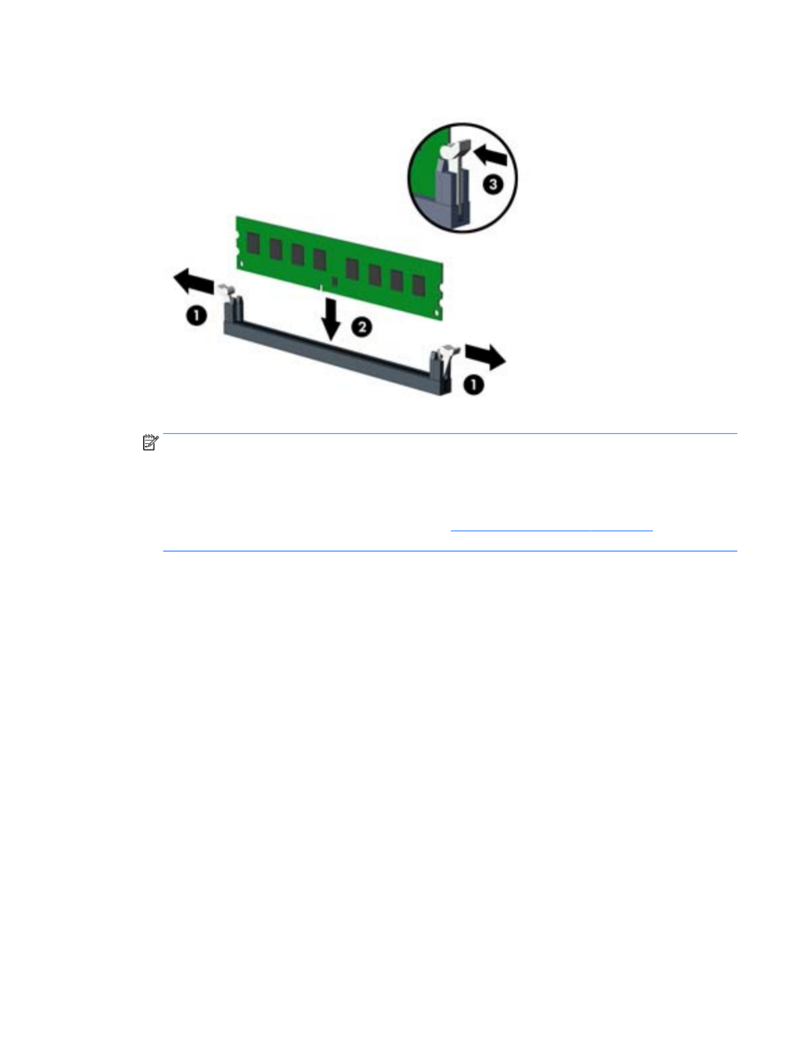
4. Open both latches of the memory module socket , and insert the memory module into the socket .(1) (2)
NOTE: A memory module can be installed in only one way. Match the notch on the module with the tab
on the memory socket.
Populate the black DIMM sockets before the white DIMM sockets.
For maximum performance, populate the sockets so that the memory capacity is spread as equally as
possible between Channel A and Channel B. Refer to Populating DIMM sockets on page 23 for more
information.
5. Push the module down into the socket, ensuring that the module is fully inserted and properly seated.
Make sure the latches are in the closed position .(3)
6. Repeat steps 4 and 5 to install any additional modules.
7. Replace the access panel.
8. If the computer was on a stand, replace the stand.
9. Reconnect the power cord and turn on the computer.
10. Lock any security devices that were disengaged when the access panel was removed.
The computer should automatically recognize the additional memory the next time you turn on the computer.
Memory 25

Expansion card
Description
nVIDIA GT730 Grayling 2 GB DDR3 PCIex8
USB 3.1 Type Cx1 PCIe p36-x1 card
Printer port, PCI card
Serial port, PCI card
PCIe to M.2 adapter
Intel PRO/1000 NIC
WLAN 802.11 a/b/g/n + Bluetooth 4.0 module
WLAN 802.11 (7265NV) a/b/g/n 2x2 + Bluetooth 4.0 module
WLAN 802.11 (7265AN) a/b/g/n 2x2
WLAN module caddy card + Bluetooth
M.2 USB cable
Wireless antenna for use with WLAN modules
The computer has two PCI Express p36-x1 expansion sockets, one PCI Express x16 expansion socket, and one PCI
Express x16 expansion socket that is downshifted to a p36-x4 socket.
NOTE: The PCI Express sockets support only low cards.prole
You can install a PCI Express x1, x4, x8, or x16 expansion card in the PCI Express x16 socket.
For dual graphics card the (primary) card must be installed in the PCI Express x16 socket congurations, rst
that is NOT downshifted to a x4.
To remove, replace, or add an expansion card:
1. Prepare the computer for disassembly (Preparation for disassembly on page 19).
2. Remove the access panel (Access panel on page 20).
3. Locate the correct vacant expansion socket on the system board and the corresponding expansion slot
on the back of the computer chassis.
26 Chapter 4 Removal and replacement procedures – small form factor (SFF) chassis

4. Release the slot cover retention latch that secures the slot covers by lifting the tab on the latch and
rotating the latch to the open position.
5. Before installing an expansion card, remove the expansion slot cover or the existing expansion card.
NOTE: Before removing an installed expansion card, disconnect any cables that may be attached to
the expansion card.
a. If you are installing an expansion card in a vacant socket, remove the appropriate expansion slot
cover on the back of the chassis. Pull the slot cover straight up then away from the inside of the
chassis.
Expansion card 27

b. If you are removing a PCI Express p38-x1 card, hold the card at each end, and carefully rock it back and
forth until the connectors pull free from the socket. Pull the expansion card straight up from the
socket (1) then away from the inside of the chassis to release it from the chassis frame (2). Be sure
not to scrape the card against the other components.
c. If you are removing a PCI Express x16 card, pull the retention arm on the back of the expansion
socket away from the card and carefully rock the card back and forth until the connectors pull free
from the socket. Pull the expansion card straight up from the socket then away from the inside of
the chassis to release it from the chassis frame. Be sure not to scrape the card against the other
components.
6. Store the removed card in anti-static packaging.
7. If you are not installing a new expansion card, install an expansion slot cover to close the open slot.
CAUTION: After removing an expansion card, you must replace it with a new card or expansion slot
cover for proper cooling of internal components during operation.
28 Chapter 4 Removal and replacement procedures – small form factor (SFF) chassis

8. To install a new expansion card, hold the card just above the expansion socket on the system board then
move the card toward the rear of the chassis (1) so that the bracket on the card is aligned with the open
slot on the rear of the chassis. Press the card straight down into the expansion socket on the system
board (2).
NOTE: When installing an expansion card, press on the card so that the whole connector seats rmly
properly in the expansion card socket.
9. Rotate the slot cover retention latch back in place to secure the expansion card.
10. Connect external cables to the installed card, if needed. Connect internal cables to the system board, if
needed.
11. Replace the computer access panel.
12. If the computer was on a stand, replace the stand.
13. Reconnect the power cord and any external devices, and then turn on the computer.
Expansion card 29

14. Lock any security devices that were disengaged when the access panel was removed.
15. Recongure the computer, if necessary.
Drives
Description
Hard drives/Solid-state drives
2-TB, 7200-rpm
1-TB, 7200-rpm, 3.5-inch
1-TB, 7200-rpm, 2.5-inch
1-TB, hybrid SSD, 3.5-inch or 2.5-inch
500-GB, 7200-rpm, 2.5-inch, SED
500 GB, 7200 rpm, 3.5-inch or 2.5-inch
500-GB, 7200-rpm, 2.5-inch, OPAL2, self-encrypting drive (SED)
500-GB, 5400-rpm, 2.5-inch, FIPS
500-GB, hybrid SSD, 2.5-inch or 2.5-inch
500-GB, 5400-rpm, 2.5-inch, 5 mm
512 GB Solid-state Drive (SSD)
512-GB Solid-state Drive (SSD), M.2, 2280SS, PCIe
256-GB Solid-state Drive (SSD), self-encrypting (SED)
256-GB Solid-state Drive (SSD)
256-GB Solid-state Drive (SSD), TLC
256-GB Solid-state Drive (SSD), M.2, 2280SS, PCIe
180 GB Solid-state Drive (SSD)
180 GB Solid-state Drive (SSD), OPAL2, MLC
128-GB Solid-state Drive (SSD), self-encrypting drive (SED)
128-GB Solid-state Drive (SSD)
128-GB Solid-state Drive (SSD), TLC
128-GB Solid-state Drive (SSD), M.2, 2280SS, PCIe
120-GB Solid-state Drive (SSD)
120-GB Solid-state Drive (SSD), OPAL2, MLC
Optical drives
DVD±RW drive
DVD-ROM drive
Blu-ray BD-Writer XL Drive
30 Chapter 4 Removal and replacement procedures – small form factor (SFF) chassis
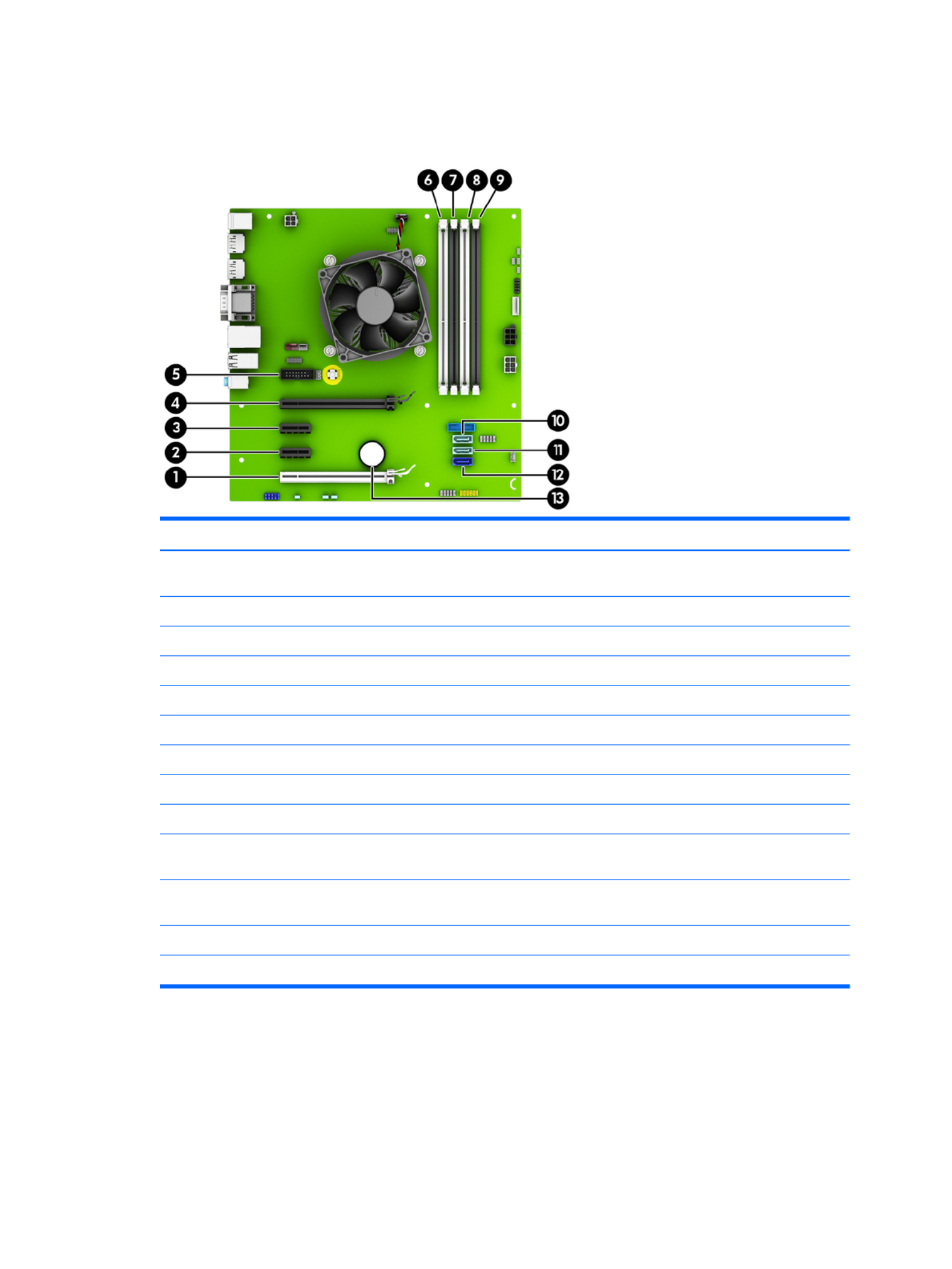
System board connections
Refer to the following illustration and table to identify the system board connectors for your model.
No. System Board Connector System Board Label Color Component
1 PCI Express x16 Gen 2
downshifted to a x4
X4PCIEXP white Expansion Card
2 PCI Express p41-x1 Gen 2 X1PCIEXP2 black Expansion Card
3 PCI Express p41-x1 Gen 2 X1PCIEXP1 black Expansion Card
4 PCI Express x16 Gen 3 X16PCIEXP black Expansion Card
5 Serial Port COMB black Optional Second Serial Port
6 DIMM4 (Channel A) DIMM4 white Memory Module
7 DIMM3 (Channel A) DIMM3 black Memory Module
8 DIMM2 (Channel B) DIMM2 white Memory Module
9 DIMM1 (Channel B) DIMM1 black Memory Module
10 SATA 3.0 SATA2 light blue Any SATA Device other than the Primary
Hard Drive
11 SATA 3.0 SATA1 light blue Any SATA Device other than the Primary
Hard Drive
12 SATA 3.0 SATA0 dark blue Primary Hard Drive
13 Battery BAT black Battery
Drives 31

Drive positions
1 9.5mm slim optical drive bay
2 3.5-inch primary hard drive bay
3 3.5-inch secondary hard drive bay
4 2.5-inch hard drive bay
NOTE: The drive on your computer may be than the drive conguration dierent
conguration shown above.
To verify the type and size of the storage devices installed in the computer, run Computer Setup.
Installing and Removing Drives
When installing drives, follow these guidelines:
●The primary Serial ATA (SATA) hard drive must be connected to the dark blue primary SATA connector on
the system board labeled SATA0.
●Connect secondary hard drives and optical drives to one of the light blue SATA connectors on the system
board (labeled SATA1 and SATA2).
32 Chapter 4 Removal and replacement procedures – small form factor (SFF) chassis
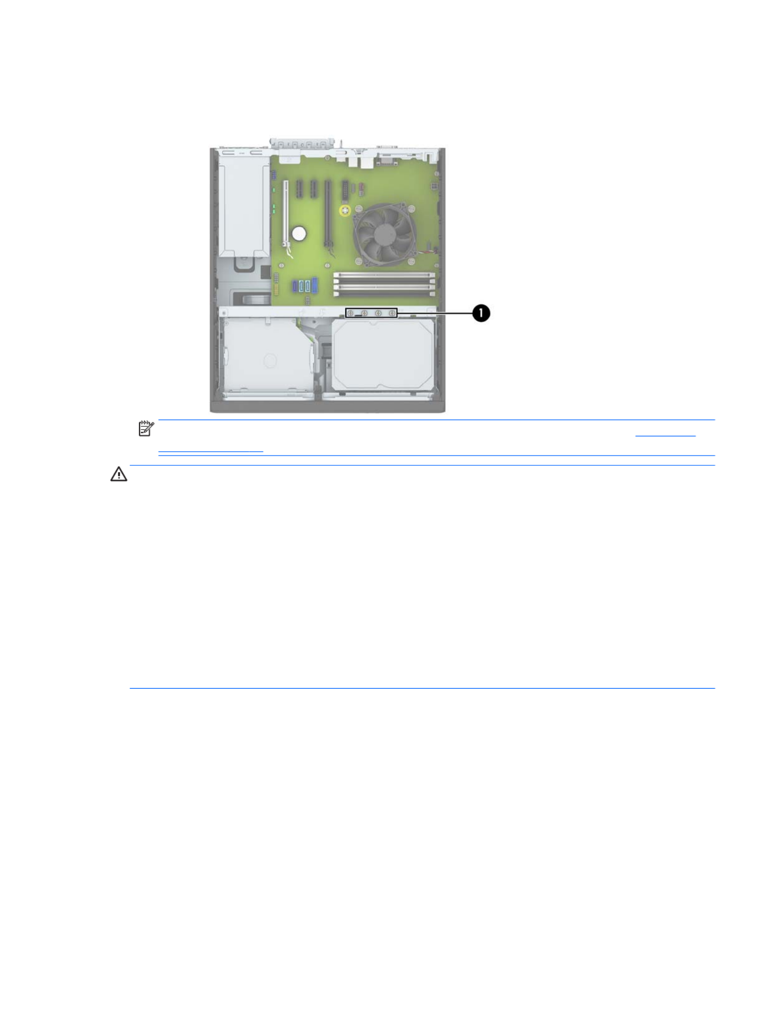
●HP has provided extra 6-32 hard drive mounting screws installed on the top of the hard drive cage (1) for
installing a hard drive into the 3.5-inch secondary hard drive bay. If you are replacing a hard drive,
remove the mounting screws from the old drive and install them in the new drive.
NOTE: You can also use one of the extra mounting screws to secure the front bezel (see Front bezel
security on page 21 for more information).
CAUTION: To prevent loss of work and damage to the computer or drive:
If you are inserting or removing a drive, shut down the operating system properly, turn the computer, and o
unplug the power cord. Do not remove a drive while the computer is on or in standby mode.
Before handling a drive, ensure that you are discharged of static electricity. While handling a drive, avoid
touching the connector.
Handle a drive carefully; do not drop it.
Do not use excessive force when inserting a drive.
Avoid exposing a hard drive to liquids, temperature extremes, or products that have magnetic such as elds
monitors or speakers.
If a drive must be mailed, place the drive in a bubble-pack mailer or other protective packaging and label the
package “Fragile: Handle With Care.”
Drives 33

Removing a 9.5mm slim optical drive
CAUTION: All removable media should be taken out of a drive before removing the drive from the computer.
1. Prepare the computer for disassembly (Preparation for disassembly on page 19).
2. Remove the access panel (Access panel on page 20).
3. Disconnect the power cable (1) and data cable (2) from the rear of the optical drive, push the green
release latch on the right rear side of the drive toward the center of the drive (3), and then slide the drive
forward and out of the bay through the front bezel (4).
CAUTION: When removing the cables, pull the tab or connector instead of the cable itself to avoid
damaging the cable.
34 Chapter 4 Removal and replacement procedures – small form factor (SFF) chassis

Installing a 9.5mm slim optical drive
1. Prepare the computer for disassembly (Preparation for disassembly on page 19).
2. Remove the access panel (Access panel on page 20).
3. Remove the front bezel if you are installing a drive in a bay covered by a bezel blank, then remove the
bezel blank. See Front bezel on page 20 for more information.
4. Align the small pin on the release latch with the small hole on the side of the drive and press the latch
rmly onto the drive.
5. Slide the optical drive through the front of the chassis all the way into the bay so that it locks in place
(1), and then connect the power cable (2) and data cable (3) to the rear of the drive.
6. Connect the opposite end of the data cable to one of the light blue SATA connectors on the system
board.
NOTE: Refer to System board connections on page 31 for an illustration of the system board drive
connectors.
Drives 35

7. Replace the front bezel if it was removed.
8. Replace the computer access panel.
9. If the computer was on a stand, replace the stand.
10. Reconnect the power cord and any external devices, and then turn on the computer.
11. Lock any security devices that were disengaged when the access panel was removed.
Removing and replacing a primary 3.5-inch hard drive
NOTE: Before you remove the old hard drive, be sure to back up the data from the old hard drive so that you
can transfer the data to the new hard drive.
1. Prepare the computer for disassembly (Preparation for disassembly on page 19).
2. Remove the access panel (Access panel on page 20).
3. Disconnect the power cable (1) and data cable (2) from the back of the hard drive.
36 Chapter 4 Removal and replacement procedures – small form factor (SFF) chassis
4. Pull the release lever next to the rear of the hard drive outward (1). While pulling the release lever out,
slide the drive back until it stops, and then lift the drive up and out of the bay (2).
5. To install a hard drive, you must transfer the mounting screws from the old hard drive to the new hard
drive.
Drives 37
6. Align the mounting screws with the slots on the chassis drive cage, press the hard drive down into the
bay, and then slide it forward until it stops and locks in place.
7. Connect the power cable (1) and data cable (2) to the back of the hard drive.
NOTE: The data cable for the primary hard drive must be connected to the dark blue connector on the
system board labeled SATA0 to avoid any hard drive performance problems.
8. Replace the computer access panel.
9. If the computer was on a stand, replace the stand.
10. Reconnect the power cord and any external devices, and then turn on the computer.
11. Lock any security devices that were disengaged when the access panel was removed.
38 Chapter 4 Removal and replacement procedures – small form factor (SFF) chassis

Removing a secondary 3.5-inch hard drive
1. Prepare the computer for disassembly (Preparation for disassembly on page 19).
2. Remove the access panel (Access panel on page 20).
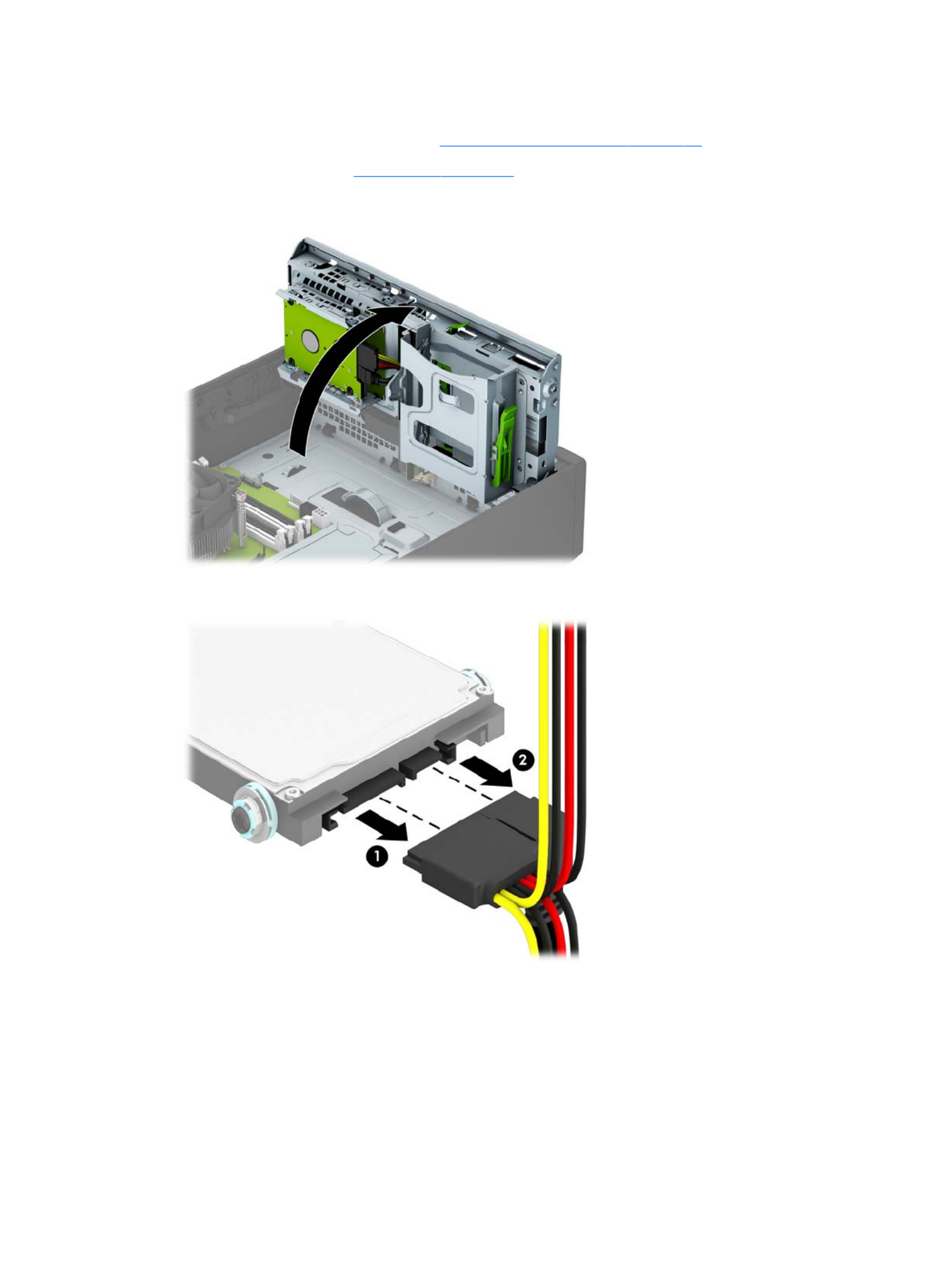
3. Rotate the drive cage to its upright position.
4. Disconnect the power cable (1) and data cable (2) from the rear of the hard drive. Press the latch on the
side of the drive cage (3), and then slide the drive out of the drive bay (4).
5. If you are installing a new drive, refer to Installing a secondary 3.5-inch hard drive on page 40. If you
are not installing a new drive, rotate the drive cage down and replace the access panel.
Drives 39

Installing a secondary 3.5-inch hard drive
1. Prepare the computer for disassembly (Preparation for disassembly on page 19).
2. Remove the access panel (Access panel on page 20).
3. Install four silver 6-32 mounting screws on the sides of the drive (two on each side).
NOTE: HP has supplied four extra silver 6-32 mounting screws installed on the chassis next to the
primary 3.5-inch hard drive bay. Refer to Installing and Removing Drives on page 32 for an illustration of
the location of the extra mounting screws.
When replacing a drive, transfer the four mounting screws from the old drive to the new drive.
4. Rotate the drive cage to its upright position.
40 Chapter 4 Removal and replacement procedures – small form factor (SFF) chassis

5. Slide the drive into the drive bay (1), and then connect the power cable (2) and data cable (3) to the rear
of the hard drive.
NOTE: If the drive is a secondary hard drive, connect the other end of data cable to one of the light
blue SATA connectors on the system board. If the drive is the primary hard drive, connect the other end
of the data cable to the dark blue SATA connector on the system board.
6. Rotate the drive cage back down to its normal position.
CAUTION: Be careful not to pinch any cables or wires when rotating the drive cage down.
7. Replace the computer access panel.
8. If the computer was on a stand, replace the stand.
9. Reconnect the power cord and any external devices, and then turn on the computer.
10. Lock any security devices that were disengaged when the access panel was removed.
Drives 41
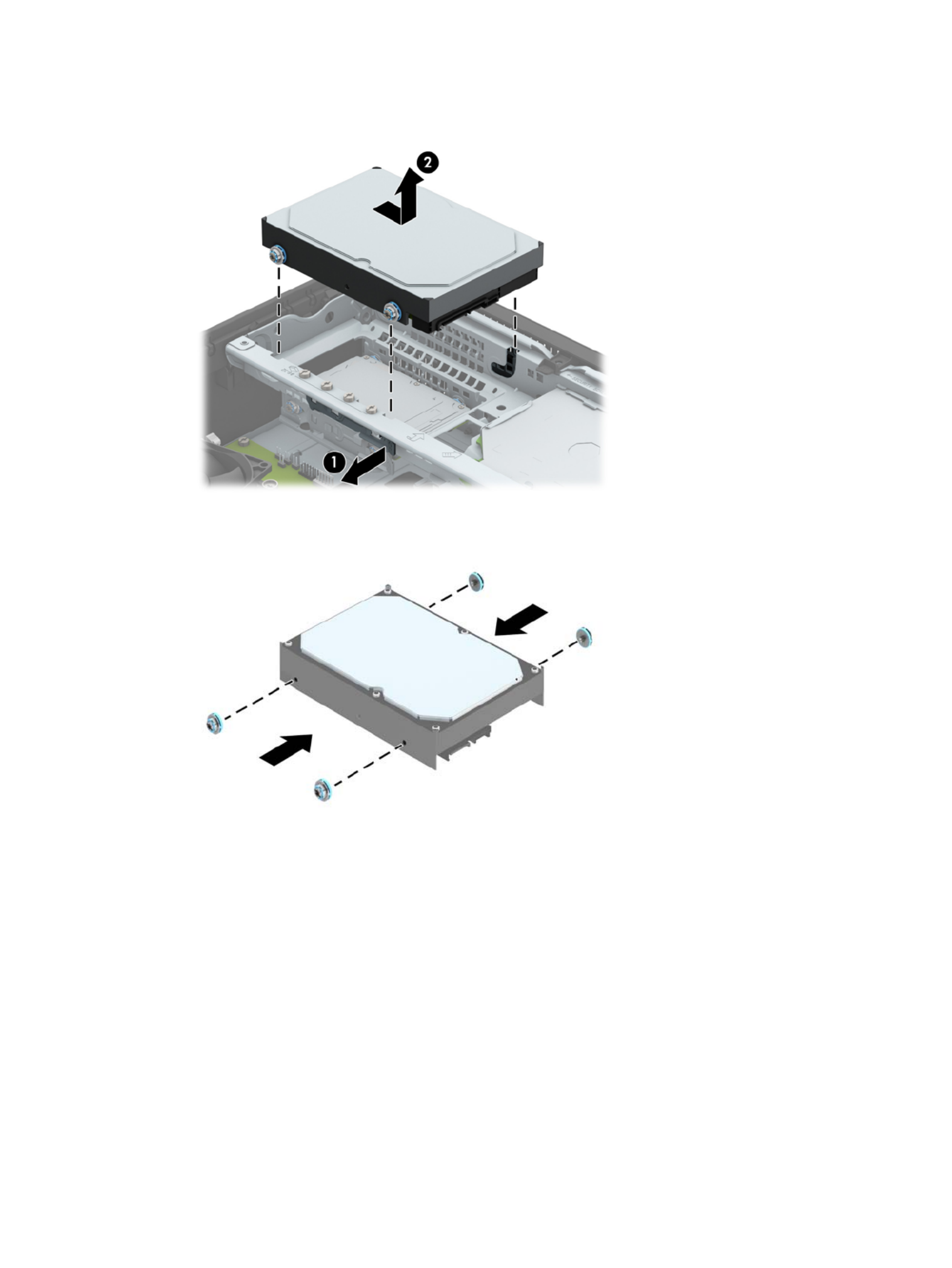
Removing a 2.5-inch hard drive
1. Prepare the computer for disassembly (Preparation for disassembly on page 19).
2. Remove the access panel (Access panel on page 20).
3. Rotate the drive cage to its upright position.
4. Disconnect the power cable (1) and data cable (2) from the back of the hard drive.
42 Chapter 4 Removal and replacement procedures – small form factor (SFF) chassis

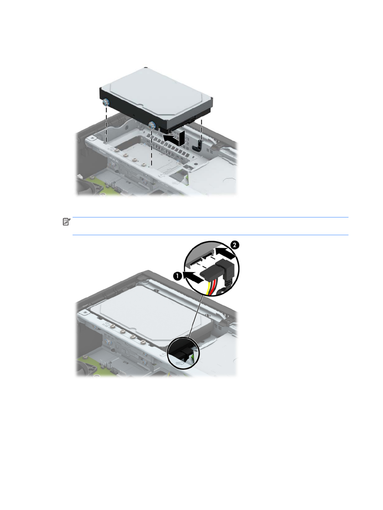
4. Rotate the drive cage to its upright position.
5. Align the mounting screws on the drive with the J-slots on the sides of the drive bay. Press the drive up
into the drive bay then slide it forward until it locks in place.
44 Chapter 4 Removal and replacement procedures – small form factor (SFF) chassis

6. Connect the power cable (1) and data cable (2) to the back of the hard drive.
NOTE: If the 2.5-inch hard drive is the primary drive, connect the other end of the data cable to the
dark blue SATA connector on the system board labeled SATA0 . If it is a secondary hard drive, connect the
other end of the data cable to one of the light blue SATA connectors on the system board.
7. Rotate the drive cage back down to its normal position.
CAUTION: Be careful not to pinch any cables or wires when rotating the drive cage down.
8. Replace the computer access panel.
9. If the computer was on a stand, replace the stand.
10. Reconnect the power cord and any external devices, and then turn on the computer.
11. Lock any security devices that were disengaged when the access panel was removed.
Drives 45

Drive power cable
1. Prepare the computer for disassembly (Preparation for disassembly on page 19).
2. Remove the access panel (Access panel on page 20).
3. Rotate the drive cage to its upright position.
4. Disconnect the cable from the system board connector labeled SATAPWR0.
5. Disconnect the cable from the hard drive and the optical drive.
6. Remove the cable from the clips on the base pan and on the drive cage, and then remove the drive
power cable from the computer.
To reinstall the drive power cable, reverse the removal procedure.
46 Chapter 4 Removal and replacement procedures – small form factor (SFF) chassis

Small bae
The small sits between the fan sink and the rear of the computer.bae
1. Prepare the computer for disassembly (Preparation for disassembly on page 19).
2. Remove the access panel (Access panel on page 20).
3. Rotate the upward.bae
4. Pull the away from the rear of the computer to disengage the clips on the from the rear of bae bae
the computer.
Small 47bae

To install the small reverse the removal procedure.bae,
Fan bae
The fan sits on top of the fan sink.bae
1. Prepare the computer for disassembly (Preparation for disassembly on page 19).
2. Remove the access panel (Access panel on page 20).
3. Remove the power cable from the clips on top of the bae.
4. Lift the the fan sink and out of the computer.bae o
To install the fan reverse the removal procedure.bae,
48 Chapter 4 Removal and replacement procedures – small form factor (SFF) chassis
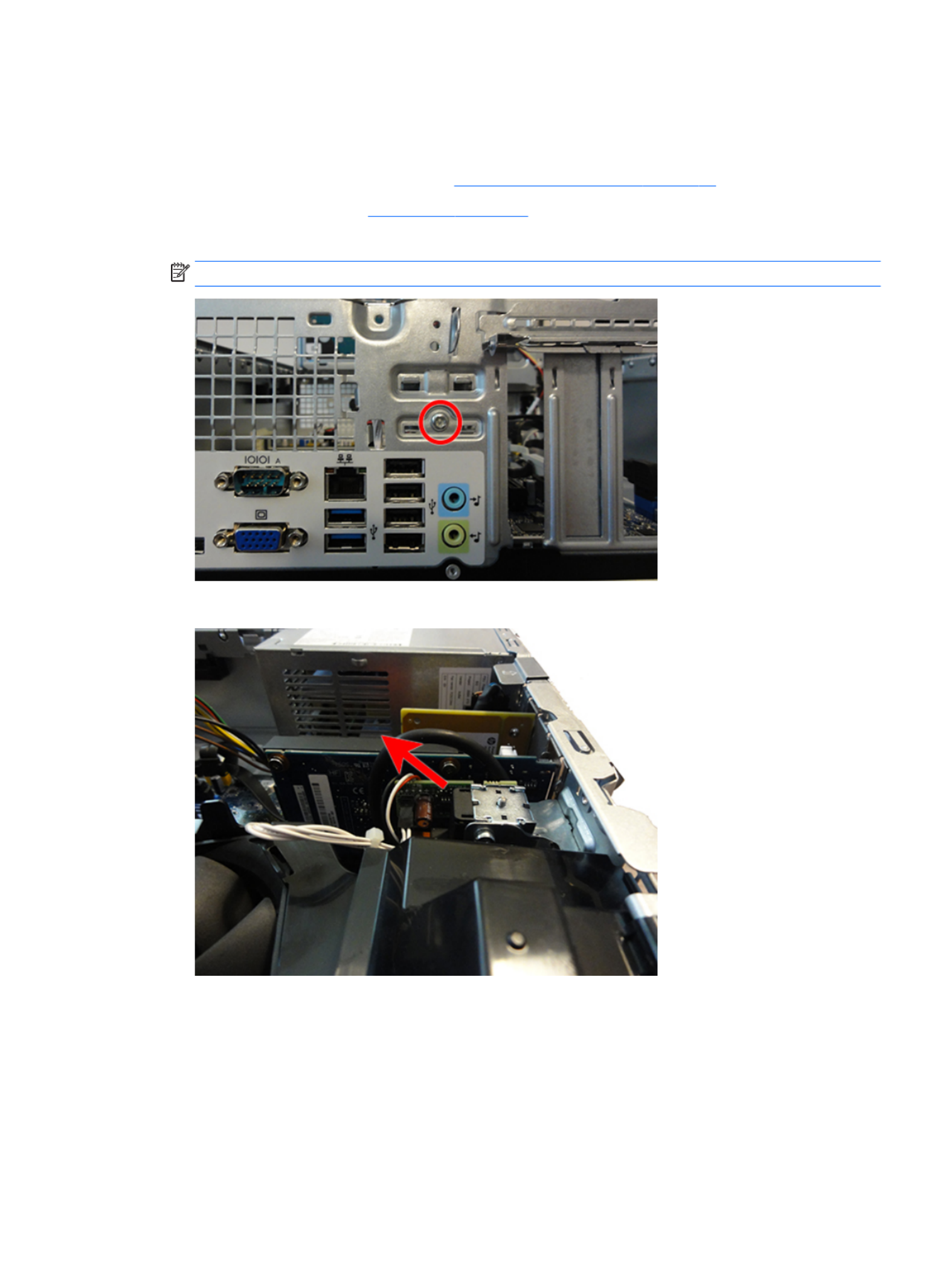
Hood lock
The hood lock is attached to the rear of the chassis.
1. Prepare the computer for disassembly (Preparation for disassembly on page 19).
2. Remove the access panel (Access panel on page 20).
3. On the rear of the computer, remove the security screw that secures the lock.
NOTE: The security screw requires a special security wrench to remove.
4. From the inside of the computer, lift the hood lock out of the computer..
To install the hood lock, reverse the removal procedure.
When installing the hood lock, on the inside rear of the computer, insert the clips on the back of the lock into
the slots on the computer rear panel , and then rotate the lock down into place .(1) (2)
Hood lock 49

50 Chapter 4 Removal and replacement procedures – small form factor (SFF) chassis
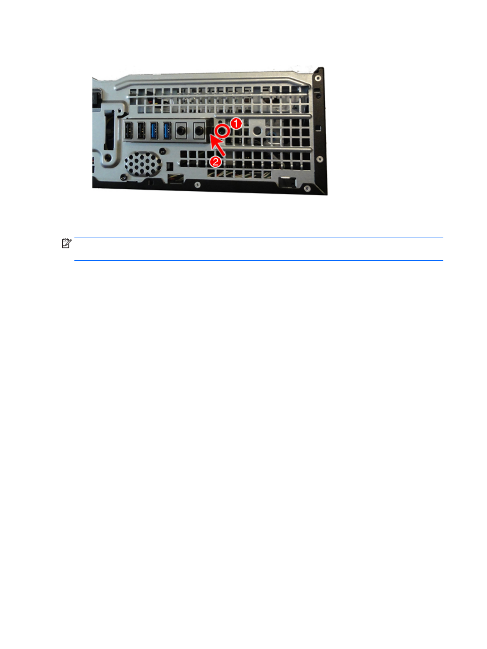
8. Press the tab on the right side of the assembly , and then push the assembly into the computer.(2)
9. Remove the front I/O assembly from the inside of the computer.
To install the front I/O assembly, reverse the removal procedure.
NOTE: Be sure to correctly route the cables beneath the drive cage when reinstalling the assembly. Proper
cable routing prevents damage to the cables and allows the drive cage to close properly.
52 Chapter 4 Removal and replacement procedures – small form factor (SFF) chassis

Power switch
The power switch is attached to the left, front of the chassis.
1. Prepare the computer for disassembly (Preparation for disassembly on page 19).
2. Remove the access panel (Access panel on page 20).
3. Remove the front bezel (Front bezel on page 20).
4. Rotate the drive cage to its upright position.
5. From the inside of the front of the chassis, press the tab at the top of the power switch and push the (1)
top of the power switch away from the front of the chassis .(2)
6. Remove the cable from the clips built into the bottom of the chassis, then and disconnect the power
switch cable from the system board connector labeled PB/LED.
7. Remove the power switch assembly from the inside of the computer.
Power switch 53

To install the power switch, reverse the removal procedures.
Speaker
The speaker is attached to the front of the chassis under the rotating drive cage.
1. Prepare the computer for disassembly (Preparation for disassembly on page 19).
2. Remove the access panel (Access panel on page 20).
3. Remove the front bezel (Front bezel on page 20).
4. Rotate the drive cage to its upright position.
5. From the outside, front of the chassis, remove the two Torx T15 screws that secure the speaker.
6. From the inside of the chassis, disconnect the speaker cable from the white system board labeled SPKR,
and the remove the speaker from the chassis.
To install the speaker, reverse the removal procedures.
54 Chapter 4 Removal and replacement procedures – small form factor (SFF) chassis

Fan sink
CAUTION: The bond between the fan sink and the processor may be very tight.
If the computer will power on, before removing the fan sink, turn on the computer until it warms the fan sink.
Warming the heat sink lessens the bond between the fan sink and the processor, thereby making separating
them easier.
Make sure not to pull the processor out of the socket when you lift the fan sink, especially if you cannot warm
the fan sink prior to removal. Inadvertently removing the processor can damage the pins.
The fan sink is secured atop the processor with four captive Torx screws. The fan sink does not include a fan.
1. Prepare the computer for disassembly (Preparation for disassembly on page 19).
2. Remove the access panel (Access panel on page 20).
3. Rotate the drive cage to its upright position.
4. Rotate the small into the upright position (bae Small on page 47bae ).
5. Remove the fan (bae Fan on page 48bae ).
6. Disconnect the fan cable from the system board connector labeled CPUFAN , and then loosen the four (1)
captive screws that secure the fan sink to the system board tray.(2)
CAUTION: Fan sink retaining screws should be removed in diagonally opposite pairs (as in an X) to even
the downward forces on the processor. This is especially important as the pins on the socket are very
fragile and any damage to them may require replacing the system board.
7. Lift the fan sink from atop the processor and set it on its side to keep from contaminating the work (3)
area with thermal grease.
When reinstalling the fan sink, make sure that its bottom has been cleaned with an alcohol wipe and fresh
thermal grease has been applied to the top of the processor.
Fan sink 55

CAUTION: Fan sink retaining screws should be tightened in diagonally opposite pairs (as in an X) to evenly
seat the fan sink on the processor to avoid damage that could require replacing the system board.
Failure to install the may cause the computer to overheat.bae
Processor
Description
AMD A10-8850B, 3.9 GHz
AMD A10-8750B, 3.6 GHz
AMD A10-7800B, 3.57 GHz
AMD A8-8650B, 3.2 GHz
AMD A8-7600B, 3.1 GHz
AMD A6-8550B, 3.7 GHz
AMD A6-8350B, 3.5 GHz
AMD A4-7300B, 3.8 GHz
1. Prepare the computer for disassembly (Preparation for disassembly on page 19).
2. Remove the access panel (Access panel on page 20).
3. Rotate the drive cage to its upright position.
4. Rotate the small into the upright position (bae Small on page 47bae ).
5. Remove the fan (bae Fan on page 48bae ).
6. Remove the heat sink (Fan sink on page 55).
7. Rotate the locking lever to its full open position .(1)
56 Chapter 4 Removal and replacement procedures – small form factor (SFF) chassis
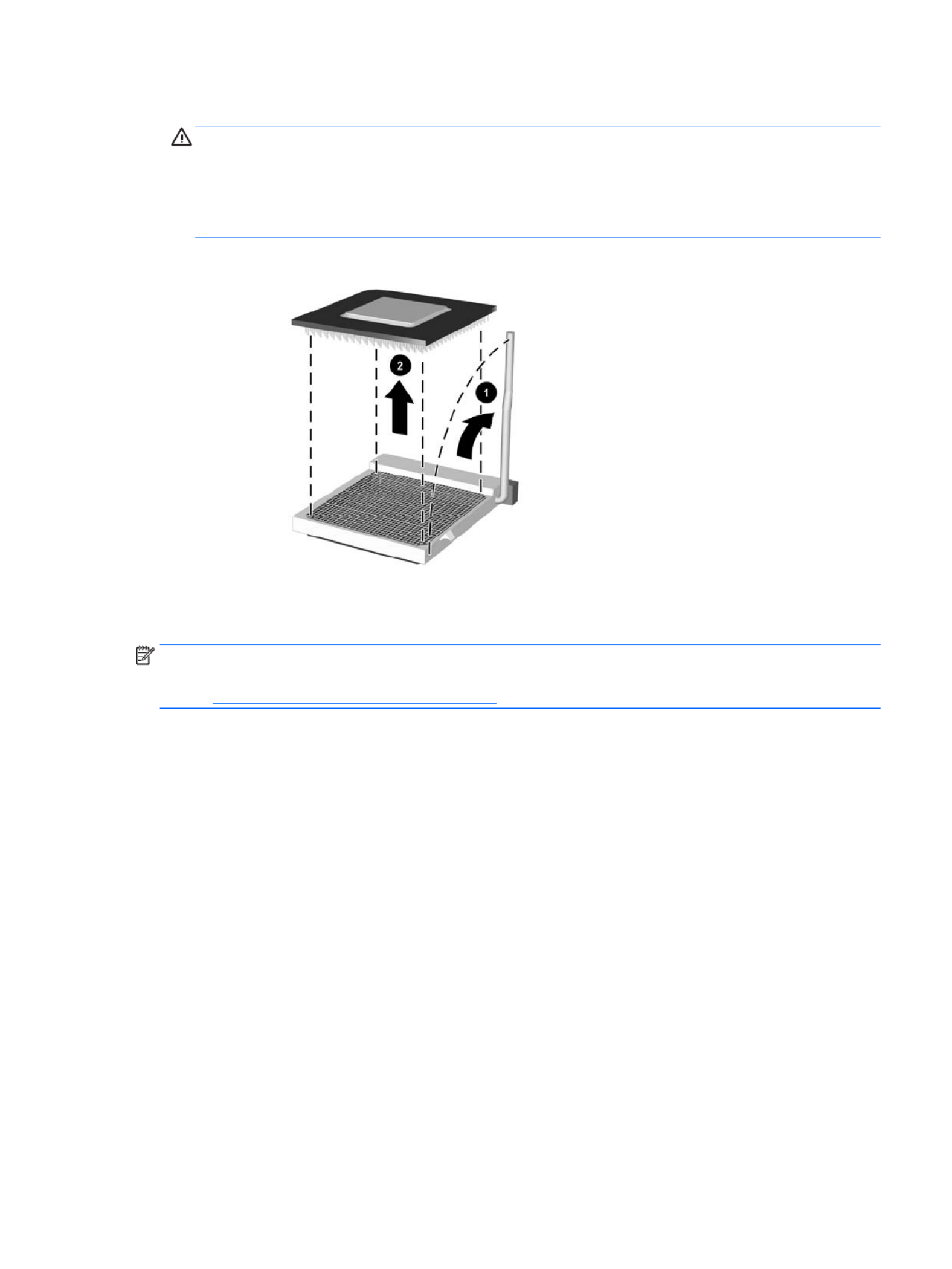
8. Carefully lift the processor from the socket .(2)
CAUTION: Do NOT handle the pins in the processor socket. These pins are very fragile and handling
them could cause irreparable damage. Once pins are damaged it may be necessary to replace the
system board.
The heat sink must be installed within 24 hours of installing the processor to prevent damage to the
processor’s solder connections.
To replace the processor, reverse the removal procedures.
NOTE: After installing a new processor onto the system board, always update the system ROM to ensure
that the latest version of the BIOS is being used on the computer. The latest system BIOS can be found on the
Web at: http://h18000.www1.hp.com/support/les.
Processor 57

Power supply
Description
Power supply, 200W, 92% ecient
Power supply, 200W, 85% ecient
Power supply, 200W, standard
WARNING! To reduce potential safety issues, only the power supply provided with the computer, a
replacement power supply provided by HP, or a power supply purchased as an accessory from HP should be
used with the computer.
WARNING! Voltage is always present on the system board when the computer is plugged into an active AC
outlet. To avoid possible personal injury and damage to the equipment the power cord should be
disconnected from the computer and/or the AC outlet before opening the computer.
1. Prepare the computer for disassembly (Preparation for disassembly on page 19).
2. Remove the access panel (Access panel on page 20).
3. Rotate the drive cage up.
4. Disconnect all power cables from the system board as follows:
●(1): PWR
●(2): PWRCMD
●(3): PWRCPU
58 Chapter 4 Removal and replacement procedures – small form factor (SFF) chassis

5. From the outside, rear of the chassis, remove the three Torx T15 that secure the power supply to the
back of the chassis.
6. From the inside of the chassis, push the release lever at the front of the power supply , slide the (1)
power supply forward, and then remove it from the chassis .(2)
To install the power supply, reverse the removal procedure.
CAUTION: When installing the power supply cables, make sure they are properly positioned so they are not
cut by the drive cage and are not pinched by the rotating power supply.
Power supply 59

System board
NOTE: All system board spare part kits include replacement thermal material.
NOTE: System board appearance may vary.
1. Prepare the computer for disassembly (Preparation for disassembly on page 19).
2. Remove the access panel (Access panel on page 20).
3. Rotate the small into the upright position (bae Small on page 47bae ).
4. Remove the fan (bae Fan on page 48bae ).
5. Rotate the drive cage to its upright position.
6. When replacing the system board, make sure the following components are removed from the defective
system board and installed on the replacement system board:
●Memory modules ( )Memory on page 23
●Expansion cards (Expansion card on page 26)
●Heat sink (Fan sink on page 55)
●Processor (Processor on page 56)
7. Disconnect all cables connected to the system board, noting their location for reinstallation.
8. Remove the eight Torx T15 screws that secure the system board to the chassis.
9. Slide the system board toward the front of the computer to disengage the I/O panel, and then lift the
system board out of the computer.
When reinstalling the system board, insert the I/O panel back into the slots in the rear of the chassis, and rst
then align the board with the chassis screw holes.
NOTE: When replacing the system board, you must change the chassis serial number in the BIOS.
60 Chapter 4 Removal and replacement procedures – small form factor (SFF) chassis

System board callouts
Sys Bd Label Color Component Sys Bd Label Color Component
PWRCPU White 4-pin processor power SATA2 Light blue Any SATA Device other
than primary hard drive
CPU Black Processor SATA1 Light blue Any SATA Device other
than primary hard drive
CPUFAN White Processor fan SPKR White Speaker
DIMM1 Black Memory module SATA0 Dark blue Hard drive
DIMM2 White Memory module FRONT USB Yellow Front I/O
DIMM3 Black Memory module BATTERY Black RTC battery
DIMM4 White Memory module FRONT AUD Blue Front I/O
PSWD Green Clear system passwords X4PCIEXP Black Expansion card
PB/LED Black Front I/O/power switch X1PCIEXP2 Black Expansion card
PWRCMD White Power supply X1PCIEXP1 Black Expansion card
SATAPWR0 Black Drives X16PCIEXP White Expansion card
PWR White 6-pin main power HLCK Black Hood lock
CMOS Yellow Reset CMOS COMB Black Optional second serial port
FRONT USB3.0 Blue Front I/O/power switch HSENSE White Hood sensor
System board 61

Using the Small Form Factor Computer in a Tower Orientation
The Small Form Factor computer can be used in a tower orientation. The HP logo plate on the front bezel is
adjustable for either desktop or tower orientation.
1. Prepare the computer for disassembly (Preparation for disassembly on page 19).
2. Orient the computer so that its right side is facing down and place the computer in the optional stand.
NOTE: To stabilize the computer in a tower orientation, HP recommends the use of the optional tower
stand.
3. Reconnect the power cord and any external devices, and then turn on the computer.
NOTE: Ensure at least 10.2 centimeters (4 inches) of space on all sides of the computer remains clear
and free of obstructions.
4. Lock any security devices that were disengaged when the access panel was removed.
62 Chapter 4 Removal and replacement procedures – small form factor (SFF) chassis

5 Computer Setup (F10) Utility
Computer Setup (F10) Utilities
Use Computer Setup (F10) Utility to do the following:
●Change factory default settings.
●View the system including settings for processor, graphics, memory, audio, storage, conguration,
communications, and input devices.
●Modify the boot order of bootable devices such as hard drives, optical drives, or USB media devices.ash
●Select Post Messages Enabled or Disabled to change the display status of Power-On Self-Test (POST)
messages. Post Messages Disabled suppresses most POST messages, such as memory count, product
name, and other non-error text messages. If a POST error occurs, the error is displayed regardless of the
mode selected. To manually switch to Post Messages Enabled during POST, press any key (except F1
through ).F12
●Establish an Ownership Tag, the text of which is displayed each time the system is turned on or
restarted.
●Enter the Asset Tag or property number assigned by the company to this computer.identication
●Enable the power-on password prompt during system restarts (warm boots) as well as during power-on.
●Establish a setup password that controls access to the Computer Setup (F10) Utility and the settings
described in this section.
●Secure integrated I/O functionality, including the serial, USB, or parallel ports, audio, or embedded NIC,
so that they cannot be used until they are unsecured.
●Enable or disable removable media boot ability.
●Solve system errors detected but not automatically during the Power-On Self-Test conguration xed
(POST).
●Replicate the system setup by saving system information on a USB device and restoring it conguration
on one or more computers.
●Enable or disable DriveLock security (when supported by drive).
Using Computer Setup (F10) Utilities
Computer Setup can be accessed only by turning the computer on or restarting the system. To access the
Computer Setup Utilities menu, complete the following steps:
1. Turn on or restart the computer.
2. Repeatedly press when the monitor light turns green to access the utility.F10
You can also press to a menu that allows you to access options available at startup, Esc dierent
including the Computer Setup utility.
NOTE: If you do not press at the appropriate time, you must restart the computer and again F10
repeatedly press when the monitor light turns green to access the utility.F10
Computer Setup (F10) Utilities 63

3. A choice of four headings appears in the Computer Setup Utilities menu: Main, Security, Advanced, and
UEFI Drivers.
NOTE: Selecting UEFI Drivers restarts the computer into the 3rd party option ROM management
application. You can access this application directly by pressing during startup.F3
4. Use the arrow (left and right) keys to select the appropriate heading. Use the arrow (up and down) keys
to select the option you want, then press Enter. To return to the Computer Setup Utilities menu, press
Esc.
5. To apply and save changes, select > .Main Save Changes and Exit
●If you have made changes that you do not want applied, select .Ignore Changes and Exit
●To reset to factory settings or previously saved default settings (some models), select Apply
Factory Defaults and Exit. This option will restore the original factory system defaults.
NOTE: Not all settings shown in the following sections are available for all models
CAUTION: Do NOT turn the computer power OFF while the BIOS is saving the Computer Setup (F10) changes
because the CMOS could become corrupted. It is safe to turn the computer only after exiting the F10 Setup o
screen.
64 Chapter 5 Computer Setup (F10) Utility

Computer Setup–Main
NOTE: Support for Computer Setup options may vary depending on the hardware specic conguration.
Table 5-1 Computer Setup—Main
Option Description
System Information Lists all information in following list if Advanced System Information is selected. Lists smaller subset if
Basic System Information is selected.
●Product name
●Installed memory size
●Processor type
●Processor cache size (L1/L2/L3)
●Processor speed
●MicroCode Revision
●Processor Stepping
●DIMM size (for each installed module)
●System BIOS version
●Integrated Video BiOS Revision
●Born On Date
●Serial Number
●SKU number
●UUID (Universally Unique Identier)
●Asset Tracking Number
●Feature Byte
●Build ID
●Product Family
●System Board ID
●System Board CT
●Integrated MAC Address
System Diagnostics Starts HP PC Hardware Diagnostics UEFI.
Lets you perform the following functions:
●Memory Test
●Hard Drive Check
●Language
Update System BIOS Lets you update the system BIOS. BIOS update binary (BIN) must be located on the system hard drive les
or on a removable USB drive under the “Hewlett-Packard\BIOS\New” folder or under the “EFI\HP\BIOS
\New” folder.
Set Machine Unique Data Lets you update the following values:
●Feature Byte
●Build ID
Computer Setup (F10) Utilities 65

Table 5-1 Computer Setup—Main (continued)
●Serial Number
●SKU Number
●Product Family
●System Board CT
●Product Name
System IDs Lets you clear the following values:
●Asset Tracking Number
●Ownership Tag
Replicated Setup Backup current settings to USB device
Saves system to a formatted USB media device.conguration ash
Restore current settings from USB device
Restores system from a USB media device.conguration ash
Save Custom Defaults Saves the current system settings as the default.conguration
Apply Custom Defaults
and Exit
Applies the currently selected default settings and clears any established passwords.
Apply Factory Defaults
and Exit
Restores the factory system settings as the default.conguration
Ignore Changes and Exit Exits Computer Setup without applying or saving any changes.
Save Changes and Exit Saves changes to system or default settings and exits Computer Setup.conguration
Suppress POST Errors Suppresses most system messages during POST (Power On Self Test).
POST error messages are displayed on the display during the Power On Self Test if the BIOS encounters a
problem while starting the computer. A POST error message will only display on screen if the computer is
capable of booting this far. If the POST detects an error before this point, a beep code is generated
instead.
66 Chapter 5 Computer Setup (F10) Utility

Table 5-2 Computer Setup—Security (continued)
CAUTION: Clearing the TPM resets it to factory defaults and turns it You will lose all created keys and o.
data protected by those keys.
Set Up BIOS Power-On
Password
Lets you set and enable a BIOS power-on password. The power-on password prompt appears after a
power cycle or reboot. If the user does not enter the correct power-on password, the unit will not boot.
Change BIOS Power-On
Password
(This selection is active
only if a BIOS power-on
password is set.)
Lets you change the BIOS power-on password.
You must know the current password to be able to change it.
DriveLock Allows you to assign or modify a master or user password for hard drives. When this feature is enabled,
the user is prompted to provide one of the DriveLock passwords during POST. If neither is successfully
entered, the hard drive will remain inaccessible until one of the passwords is successfully provided during
a subsequent cold-boot sequence.
NOTE: This selection will only appear when at least one drive that supports the DriveLock feature is
attached to the system.
CAUTION: Be aware that these settings take place immediately. A save is not necessary.
CAUTION: Be sure to document the DriveLock password. Losing a DriveLock password will render a drive
permanently locked.
After you select a drive, the following options are available:
Set DriveLock Master Password. Sets the drive’s master password but does not enable DriveLock.
Enable DriveLock. Sets the drive’s user password and enables DriveLock.
Secure Erase Lets you select a hard drive to completely erase.
Once a hard drive has been erased with a program that utilizes Secure Erase commands, no rmware le
recovery program, partition recovery program, or other data recovery method will be able to extract data
from the drive.
Save/Restore MBR of the
system hard drive
Enabling this feature will save the Master Boot Record (MBR) of the system hard drive. If the MBR gets
changed, the user will be prompted to restore the MBR. Default is disabled.
The MBR contains information needed to successfully boot from a disk and to access the data stored on
the disk. Master Boot Record Security may prevent unintentional or malicious changes to the MBR, such as
those caused by some viruses or by the incorrect use of certain disk utilities. It also allows you to recover
the "last known good" MBR, should changes to the MBR be detected when the system is restarted.
When MBR Security is enabled, the BIOS prevents any changes being made to the MBR of the current
bootable disk while in MS-DOS or Windows Safe Mode.
NOTE: Most operating systems control access to the MBR of the current bootable disk; the BIOS cannot
prevent changes that may occur while the operating system is running.
Restores the backup Master Boot Record to the current bootable disk. Default is disabled.
Only appears if all of the following conditions are true:
●MBR security is enabled
●A backup copy of the MBR has been previously saved
●The current bootable disk is the same disk from which the backup copy was saved
CAUTION: Restoring a previously saved MBR after a disk utility or operating system has the modied
MBR, may cause the data on the disk to become inaccessible. Only restore a previously saved MBR if you
are that the current bootable disk's MBR has been corrupted or infected with a virus.condent
Smart Cover Cover Lock (Lock/Unlock)
Default is ‘Unlock’.
68 Chapter 5 Computer Setup (F10) Utility

Table 5-2 Computer Setup—Security (continued)
Cover Removal Sensor (Disabled/Notify user/Administrator password)
Lets you disable the cover sensor or what action is taken if the computer cover was removed. congure
Default is ‘Disabled’.
NOTE: Notify user alerts the user that the sensor has detected that the cover has been removed.
Administrator Password requires that the password be entered to boot the computer if the sensor
detects that the cover has been removed.
System Management
Command
Allows authorized personnel to reset security settings during a service event. Default is enabled.
Restore Security
Settings to Default
Restoring settings to default requires the BIOS Administrator password.
Computer Setup—Advanced
NOTE: Support for Computer Setup options may vary depending on the hardware specic conguration.
Table 5-3 Computer Setup—Advanced (for advanced users)
Option Heading
Select Language Lets you select the language of the menus in F10 Setup.
Select Keyboard Layout Lets you select language for the keyboard.
Boot Options Startup Menu Delay(sec)
Enabling this feature will add a delay to the POST process. This delay is sometimes needed user-specied
for hard disks on some PCI cards that spin up very slowly, so slowly that they are not ready to boot by the
time POST is The POST delay also gives you more time to select to enter Computer (F10) nished. F10
Setup. Default is ‘0’.
Select the devices that the computer can boot from, as well as other options, including:
●Fast Boot. Default is disabled.
●CD-ROM Boot. Default is enabled.
●Network (PXE) Boot. Default is enabled.
●SD Boot. Default is enabled.
●Netclone BIOS Boot. Default is disabled.
●Prompt on Memory Size Change. Default is enabled.
●Prompt on Fixed Storage Change. Default is disabled.
●Display Diagnostic URL. Default is enabled.
●UEFI Boot Order. Default is enabled.
●Specify the order in which UEFI boot sources (such as a internal hard drive, USB hard drive, USB
optical drive, or internal optical drive) are checked for a bootable operating system image. Each
device on the list may be individually excluded from or included for consideration as a bootable
operating system source.
UEFI boot sources always have precedence over legacy boot sources.
●Legacy Boot Order
Specify the order in which legacy boot sources (such as a network interface card, internal hard drive,
USB optical drive, or internal optical drive) are checked for a bootable operating system image. Each
Computer Setup (F10) Utilities 69

Table 5-3 Computer Setup—Advanced (for advanced users) (continued)
device on the list may be individually excluded from or included for consideration as a bootable
operating system source.
Specify the order of attached hard drives. The hard drive in the order will have priority in the rst
boot sequence and will be recognized as drive C (if any devices are attached).
NOTE: To drag a device to a preferred place, press Enter. To remove the device from consideration as a
bootable device, press .F5
You can use to disable individual boot items, as well as disable UEFI boot and/or legacy boot.F5
NOTE: MS-DOS drive lettering assignments may not apply after a non-MS-DOS operating system has
started.
Shortcut to Temporarily Override Boot Order
To boot from a device other than the default device in Boot Order, restart the computer one time specied
and press (to access the boot menu) and then (Boot Order), or only (skipping the boot menu) Esc F9 F9
when the monitor light turns green. After POST is completed, a list of bootable devices is displayed. Use
the arrow keys to select the preferred bootable device and press Enter. The computer then boots from the
selected non-default device for this one time.
Secure Boot
Conguration
Congure Legacy Support and Secure Boot
Legacy Support – Lets you turn all legacy support on the computer, including booting to DOS, running o
legacy graphics cards, booting to legacy devices, and so on.
Secure Boot – Lets you make sure an operating system is legitimate before booting to it, making Windows
resistant to malicious from preboot to full OS booting, preventing attacks. UEFI and modication rmware
Windows Secure Boot only allow code signed by pre-approved digital to run during the certicates
rmware and OS boot process.
Default is ‘Legacy Support Enable and Secure Boot Disable’.
Secure Boot Key Management
Lets you manage the custom key settings.
Clear Secure Boot Keys
Lets you delete any previously loaded custom boot keys. Clearing keys will disable secure boot. Default is
disabled.
Reset Security Boot keys to factory defaults
Default is disabled.
System Options Onboard RAID (enable/disable)
Lets you enable onboard RAID. Default is disabled.
Max SATA Speed (6.0 Gbps/3.0Gbps)
Lets you set the maximum SATA drive speed to either 3.0 Gbps or 6.0 Gbps. The default is ‘6.0 Gbps’.
USB 3.0 (XHCI) (enable/disable)
Lets you enable the eXtensible Host Controller Interface (xHCI). If enabled, the USB 3.0 ports are routed to
the xHCI controller before booting to OS. If disabled, the USB 3.0 ports are routed to the EHCI controller
before booting to OS. The default is disabled.
After Power Loss state). Default is Power Setting this option to:(o/on/previous o.
●Power the computer to remain powered when power is restored.o—causes o
●Power on—causes the computer to power on automatically as soon as power is restored.
●Previous state—causes the computer to power on automatically as soon as power is restored, if it
was on when power was lost.
SVM CPU VIrtualization (enable/disable)
70 Chapter 5 Computer Setup (F10) Utility
Produktspezifikationen
| Marke: | HP |
| Kategorie: | Desktop |
| Modell: | EliteDesk 705 G2 |
| Breite: | 338 mm |
| Tiefe: | 380 mm |
| Gewicht: | 6600 g |
| Produkttyp: | PC Barebone |
| Produktfarbe: | Schwarz |
| Höhe: | 100 mm |
| Kopfhörerausgänge: | 1 |
| Anzahl USB 2.0 Anschlüsse: | 4 |
| Eingebauter Ethernet-Anschluss: | Ja |
| Schnellstartübersicht: | Ja |
| Zertifizierung: | EPEAT Gold |
| Anzahl Ethernet-LAN-Anschlüsse (RJ-45): | 1 |
| Stromversorgung: | 200 W |
| Audio-System: | Realtek ALC221 |
| Ein-/Ausschalter: | Ja |
| Mikrofon-Eingang: | Ja |
| Netzteiltyp: | Interne Stromversorgungseinheit |
| Prozessorfamilie: | AMD |
| Kompatible Betriebssysteme: | - Windows 10 Pro 64 bit, Windows 10 Home 64 bit, Windows 8.1 Pro 64 bit, Windows 8.1 64 bit, Windows 7 Professional 64 bit, Windows 7 Professional 32 bit, Windows 7 Professional 64 bit, Windows 7 Professional 32 bit\n- NeoKylin Linux 64\n- FreeDOS 2.0 |
| Unterstützte Speicherlaufwerke: | HDD & SSD |
| USB 3.2 Gen 1 (3.1 Gen 1) Anzahl der Anschlüsse vom Typ A: | 6 |
| Gehäusetyp: | SFF |
| Tastatur enthalten: | Ja |
| Anzahl VGA (D-Sub) Anschlüsse: | 1 |
| Kompatible Prozessoren: | AMD A |
| Motherboard Chipsatz: | AMD A58 |
| Anzahl der Speichersteckplätze: | 4 |
| Arbeitsspeicher Typ: | DIMM |
| RAM-Speicher maximal: | 32 GB |
| Anzahl PS/2 Anschlüsse: | 11 |
| Nachhaltigkeitszertifikate: | ENERGY STAR |
| Eingebauter Prozessor: | Nein |
| Anzahl serielle Anschlüsse: | 1 |
| Eingebaute Grafikadapter: | Ja |
| Optisches Laufwerk - Typ: | DVD Super Multi |
| Anzahl DisplayPort Anschlüsse: | 2 |
| Grafikkarte-Familie: | AMD |
| Trusted Platform Module (TPM): | Ja |
| PCI-Express x16-Slots: | 1 |
| PCI-Express x1-Slots: | 2 |
| Intel HD-Audio-Technik: | Ja |
| Anzahl von Stromversorgungseinheiten: | 1 |
| unterstützte Speicherlaufwerksgrößen: | 2.5,3.5 Zoll |
| Trusted Platform Module (TPM) Version: | 1.2 |
Brauchst du Hilfe?
Wenn Sie Hilfe mit HP EliteDesk 705 G2 benötigen, stellen Sie unten eine Frage und andere Benutzer werden Ihnen antworten
Bedienungsanleitung Desktop HP

29 September 2024
15 September 2024
10 September 2024
4 September 2024
2 September 2024
28 August 2024
26 August 2024
24 August 2024
22 August 2024
21 August 2024
Bedienungsanleitung Desktop
- Desktop Samsung
- Desktop Acer
- Desktop Apple
- Desktop Asus
- Desktop BenQ
- Desktop Gigabyte
- Desktop Medion
- Desktop Microsoft
- Desktop Sharkoon
- Desktop Sony
- Desktop LG
- Desktop Sharp
- Desktop WOOOD
- Desktop Haier
- Desktop TrekStor
- Desktop Optoma
- Desktop PEAQ
- Desktop Toshiba
- Desktop Mio
- Desktop ViewSonic
- Desktop Dell
- Desktop LC-Power
- Desktop Lenovo
- Desktop MSI
- Desktop JYSK
- Desktop Tripp Lite
- Desktop Razer
- Desktop ELO
- Desktop Targa
- Desktop Xoro
- Desktop Vtech
- Desktop Parisot
- Desktop Wehkamp
- Desktop Supermicro
- Desktop Faytech
- Desktop InFocus
- Desktop NEC
- Desktop Seagate
- Desktop Fujitsu
- Desktop Maxdata
- Desktop Packard Bell
- Desktop Kogan
- Desktop ZTE
- Desktop Atari
- Desktop Kramer
- Desktop Asrock
- Desktop ECS
- Desktop Promethean
- Desktop Vorago
- Desktop Emachines
- Desktop Ibm
- Desktop MP
- Desktop ONYX
- Desktop Alienware
- Desktop Zotac
- Desktop Intel
- Desktop Moxa
- Desktop VXL
- Desktop Planar
- Desktop Shuttle
- Desktop Altra
- Desktop Axis
- Desktop Advantech
- Desktop Elitegroup
- Desktop BDI
- Desktop Bestar
- Desktop Pelco
- Desktop Foxconn
- Desktop System76
- Desktop NComputing
- Desktop Cybernet
- Desktop Aopen
- Desktop Smart Things
- Desktop Zoostorm
- Desktop Dell Wyse
- Desktop MvixUSA
- Desktop AIS
- Desktop Wyse
Neueste Bedienungsanleitung für -Kategorien-

30 November 2024

15 Oktober 2024

14 Oktober 2024
12 Oktober 2024
11 Oktober 2024

9 Oktober 2024

9 Oktober 2024

7 Oktober 2024
4 Oktober 2024
4 Oktober 2024