HP CQ58-104SR Bedienungsanleitung
Lesen Sie kostenlos die 📖 deutsche Bedienungsanleitung für HP CQ58-104SR (104 Seiten) in der Kategorie Laptop. Dieser Bedienungsanleitung war für 13 Personen hilfreich und wurde von 2 Benutzern mit durchschnittlich 4.5 Sternen bewertet
Seite 1/104

Compaq Presario CQ58
Maintenance and Service Guide

© Copyright 2012 Hewlett-Packard
Development Company, L.P.
AMD, the AMD Arrow logo, and
combinations thereof, are trademarks of
Advanced Micro Devices, Inc. Bluetooth is a
trademark owned by its proprietor and used
by Hewlett-Packard Company under license.
Microsoft, Windows, and Windows Vista
are U.S. registered trademarks of Microsoft
Corporation. SD Logo is a trademark of
its proprietor.
The information contained herein is subject
to change without notice. The only
warranties for HP products and services are
set forth in the express warranty statements
accompanying such products and services.
Nothing herein should be construed as
constituting an additional warranty. HP shall
not be liable for technical or editorial errors
or omissions contained herein.
First Edition: May 2012
Document Part Number: 679370-001

Safety warning notice
WARNING! To reduce the possibility of heat-related injuries or of overheating the device, do not
place the device directly on your lap or obstruct the device air vents. Use the device only on a hard, flat
surface. Do not allow another hard surface, such as an adjoining optional printer, or a soft surface,
such as pillows or rugs or clothing, to block airflow. Also, do not allow the AC adapter to contact the
skin or a soft surface, such as pillows or rugs or clothing, during operation. The device and the AC
adapter comply with the user-accessible surface temperature limits defined by the International
Standard for Safety of Information Technology Equipment (IEC 60950).
iii

iv Safety warning notice

Table of contents
1 Product description ........................................................................................................... 1
2 External component identification ..................................................................................... 5
Finding your hardware and software information ......................................................................... 5
Display ................................................................................................................................... 5
Button ..................................................................................................................................... 7
Keys ....................................................................................................................................... 8
Lights ...................................................................................................................................... 9
TouchPad .............................................................................................................................. 10
Front ..................................................................................................................................... 10
Left side ................................................................................................................................ 11
Right side .............................................................................................................................. 13
Bottom .................................................................................................................................. 14
3 Illustrated parts catalog .................................................................................................. 15
Service tag ............................................................................................................................ 16
Computer major components ................................................................................................... 17
Display assembly subcomponents ............................................................................................. 20
Mass storage devices ............................................................................................................. 22
Miscellaneous parts ................................................................................................................ 23
Sequential part number listing .................................................................................................. 24
4 Removal and replacement procedures ............................................................................ 27
Preliminary replacement requirements ....................................................................................... 27
Tools required ......................................................................................................... 27
Service considerations ............................................................................................. 27
Plastic parts ............................................................................................. 27
Cables and connectors ............................................................................. 27
Drive handling ......................................................................................... 28
Grounding guidelines .............................................................................................. 28
Electrostatic discharge damage .................................................................. 28
v

Packaging and transporting guidelines ........................................ 30
Component replacement procedures ........................................................................................ 32
Service tag ............................................................................................................. 32
Computer feet ......................................................................................................... 33
Battery ................................................................................................................... 34
Memory module ...................................................................................................... 35
WLAN module ........................................................................................................ 36
Keyboard ............................................................................................................... 38
Optical drive .......................................................................................................... 42
Hard drive ............................................................................................................. 44
RTC battery ............................................................................................................ 47
Top cover ............................................................................................................... 48
Power button board ................................................................................................. 51
TouchPad button board ............................................................................................ 52
Optical drive connector cable ................................................................................... 55
Speakers ................................................................................................................ 57
USB board ............................................................................................................. 59
System board ......................................................................................................... 61
Fan/heat sink assembly ........................................................................................... 63
Display assembly .................................................................................................... 66
Power connector cable ............................................................................................ 75
5 Using Setup Utility (BIOS) and System Diagnostics ........................................................... 77
Starting Setup Utility (BIOS) ..................................................................................................... 77
Updating the BIOS ................................................................................................................. 77
Determining the BIOS version ................................................................................... 78
Downloading a BIOS update .................................................................................... 78
Using System Diagnostics ........................................................................................................ 79
6 Specifications ................................................................................................................. 80
Computer specifications .......................................................................................................... 80
15.6-in, SVA, display panel display specifications ..................................................................... 81
Hard drive specifications ........................................................................................................ 82
7 Backup and recovery ...................................................................................................... 83
Restore ................................................................................................................................. 83
Creating recovering media ...................................................................................................... 84
Performing a system restore ..................................................................................................... 85
Restoring using the dedicated recovery partition (select models only) ............................. 85
Restoring using the recovery media ........................................................................... 86
vi

Changing the computer boot order ............................................................................ 86
Backing up and recovering your information ............................................................................. 87
Using Windows Backup and Restore ......................................................................... 88
Using Windows system restore points ........................................................................ 88
When to create restore points .................................................................... 88
Create a system restore point ..................................................................... 88
Restore to a previous date and time ............................................................ 89
8 Power cord set requirements .......................................................................................... 90
Requirements for all countries .................................................................................................. 90
Requirements for specific countries and regions ......................................................................... 91
9 Recycling ........................................................................................................................ 92
Index ................................................................................................................................. 93
vii

viii

1 Product description
Category Description
Product Name Compaq Presario CQ58
Processors ●AMD® E2-1800 processor (1.70-GHz, 1333-MHz, 18 W, dual core; not
supported on computer models equipped with Windows® 7 Starter 32-bit
operating systems)
●AMD E1-1200 processor (1.40-GHz, 1066-MHz, 18 W, dual core; not
supported on computer models equipped with Windows 7 Starter 32-bit
operating systems)
●AMD E-300 processor (1.30-GHz, 1066-MHz, 18 W, dual core)
Processor is soldered to the system board
Chipset AMD A68M fusion controller hub (FCH)
Graphics Internal graphics:
●AMD Radeon™ 7340 Series Graphics on computer models equipped with an
AMD E2-1800 processor
●AMD Radeon 7310 Series Graphics on computer models equipped with an AMD
E1-1200 processor
●AMD Radeon HD 6310M Discrete-Class Graphics on computer models equipped
with an AMD E-300 processor
Supports HD decode, DX11, and HDMI
Panel 15.6-in, light-emitting diode (LED), SVA, HD, BrightView (1366×768) display; typical
brightness: 200 nits
All display assemblies include one or two wireless local area network (WLAN)
antenna cables
Supports low voltage differential signalling (LVDS)
1

Category Description
Memory Two customer-accessible/upgradable memory module slots
DDR3-1333-MHz single channel support (DDR3-1600 downgrade to DDR3-1333) on
computer models equipped with an AMD E2-1800 processor
DDR3-1066-MHz single channel support (DDR3-1600 downgrade to DDR3-1066) on
computer models equipped with an AMD E1-1200 or E-300 processor
Supports 8192-MB of system RAM in the following configurations:
●8192-MB (4096-MB×2; not supported on computer models equipped with a 32-
bit operating system)
●6144-MB (4096-MB+2048×1; not supported on computer models equipped with
a 32-bit operating system)
●4086-MB (4096-MB×1 or 2048×2; not supported on computer models equipped
with Windows 7, 32-bit operating system)
●2048-MB (2048×1; not supported on computer models equipped with Windows
7, 32-bit operating system)
Hard drive Supports 6.35-cm (2.5-in) hard drives in 9.5-mm (.37-in) and 7.0-mm (.28-in)
thicknesses (all hard drives use the same bracket)
Customer-accessible
Serial ATA
Supports the following hard drives:
●750-GB, 5400-rpm, 9.5-mm
●640-GB, 5400-rpm, 9.5-mm
●500-GB, 5400-rpm, 9.5-mm
●320-GB, 5400-rpm, 9.5-mm
Optical drive Fixed
Serial ATA
12.7-mm tray load
Supports DVD±RW Double-Layer with SuperMulti Drive
Supports zero power optical drive
Audio and video Two Altec-Lansing speakers
HD audio
Supports Microsoft premium requirements
VGA webcamera (fixed, no tilt with activity LED; 640×480 by 24 frames per second)
One digital microphone
Ethernet Integrated 10/100 network interface card (NIC)
Wireless Integrated wireless local area network (WLAN) options by way of wireless module
2 Chapter 1 Product description

Category Description
One or two WLAN antennas built into display assembly, varying by computer model
Support for the following WLAN formats:
●Atheros AR9565 802.11b/g/n 1×1 WiFi + BT4.0 Combo Adapter
●Atheros HB125 802.11b/g/n 1×1 WLAN module
●Atheros 9485GN 802.11b/g/n 1×1 WiFi and 3012 Bluetooth 4.0
Combo Adapter
●Broadcom 4313GN 802.11b/g/n 1×1 WiFi and 20702 Bluetooth 4.0
Combo Adapter
●Ralink RT5390F 802.11b/g/n 1×1 WLAN module
●Ralink RT5390R 802.11bg/n 1×1 WiFi Adapter
●Ralink RT3290LE 802.11b/g/n 1×1 WiFi and Bluetooth 4.0 Combo Adapter
External media cards HP Multi-Format Digital Media reader with push-push technology, supporting:
●Secure Digital (SD) Memory Card
●Secure Digital Extended Capacity (SDxC) Memory Card
●Secure Digital High Capacity (SDHC) Memory Card
●MultiMediaCard (MMC)
Ports ●Audio-in (mono microphone)
●Audio-out (stereo headphone)
●HDMI v1.4 supporting: up to 1920×1200 @ 60Hz
●HP Smart AC adapter
●RJ-45 (Ethernet Gigabit support with LED indicators)
●USB 2.0 ports on computer: 3 (2 on one side, 1 on other; USB port allocation: 3
for the computer, 1 for camera 1 for MiniCard)
●VGA (Dsub 15 pin) supporting: 2048×1536 external resolution @ 60 Hz, hot
plug and unplug and autodetection for correct output to wide-aspect vs. standard
aspect video
Keyboard/pointing devices Full-size (15.6-in.), textured, pocket keyboard, no numeric keypad
Gesture support: MultiTouch gestures enabled, two-finger scrolling, and pinch-zoom
as default
Taps enabled by default
Power requirements 65W RC, V, EM, 3-wire HP Smart AC adapter with localized cable plug support (3-
wire plug with ground pin, supports 3-pin DC connector)
Supports the following batteries:
●6-cell, 55-Wh, 2.55-Ah, Li-ion battery
●6-cell, 47-Wh, 2.20-Ah, Li-ion battery
3

Category Description
Security Supports security cable lock
Operating system Preinstalled:
●Windows® 7 Home Basic 64-bit
●Windows 7 Home Premium 64-bit
●Windows 7 Starter 32-bit (not supported on computer models equipped with a
750-, 640-, or 500-GB hard drive)
●FreeDOS
Serviceability End user replaceable parts:
●AC adapter
●Battery
●Hard drive
●Memory module
●Optical drive
●WLAN module
4 Chapter 1 Product description
2 External component identification
Finding your hardware and software information
▲Select Start > Computer.
A list displays all the devices installed in your computer, including hard drive, optical drives, solid-state
drives (SSD), or a secondary hard drive.
To find out what software is included on your computer, select Start > All Programs.
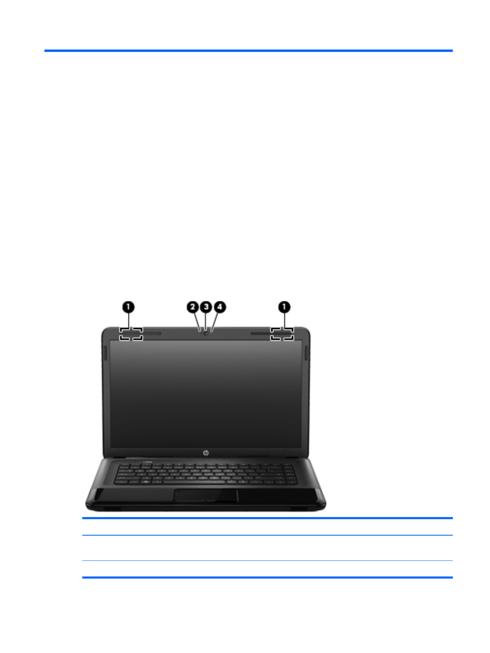
Display
Item Component Description
(1) WLAN antennas (2)* Send and receive wireless signals to communicate
with WLANs.
(2) Internal microphone Records sound.
Finding your hardware and software information 5

Item Component Description
(3) Webcam Records video, captures still photographs, and allows
video conferences and online chat by means of
streaming video.
To use the webcam, select Start > All Programs >
Communication and Chat > CyberLink YouCam.
(4) Webcam light On: The webcam is in use.
*The antennas are not visible from the outside of the computer. For optimal transmission, keep the areas immediately around
the antennas free from obstructions. For wireless regulatory notices, see the section of the Regulatory, Safety, and
Environmental Notices that applies to your country or region. These notices are located in Help and Support.
6 Chapter 2 External component identification
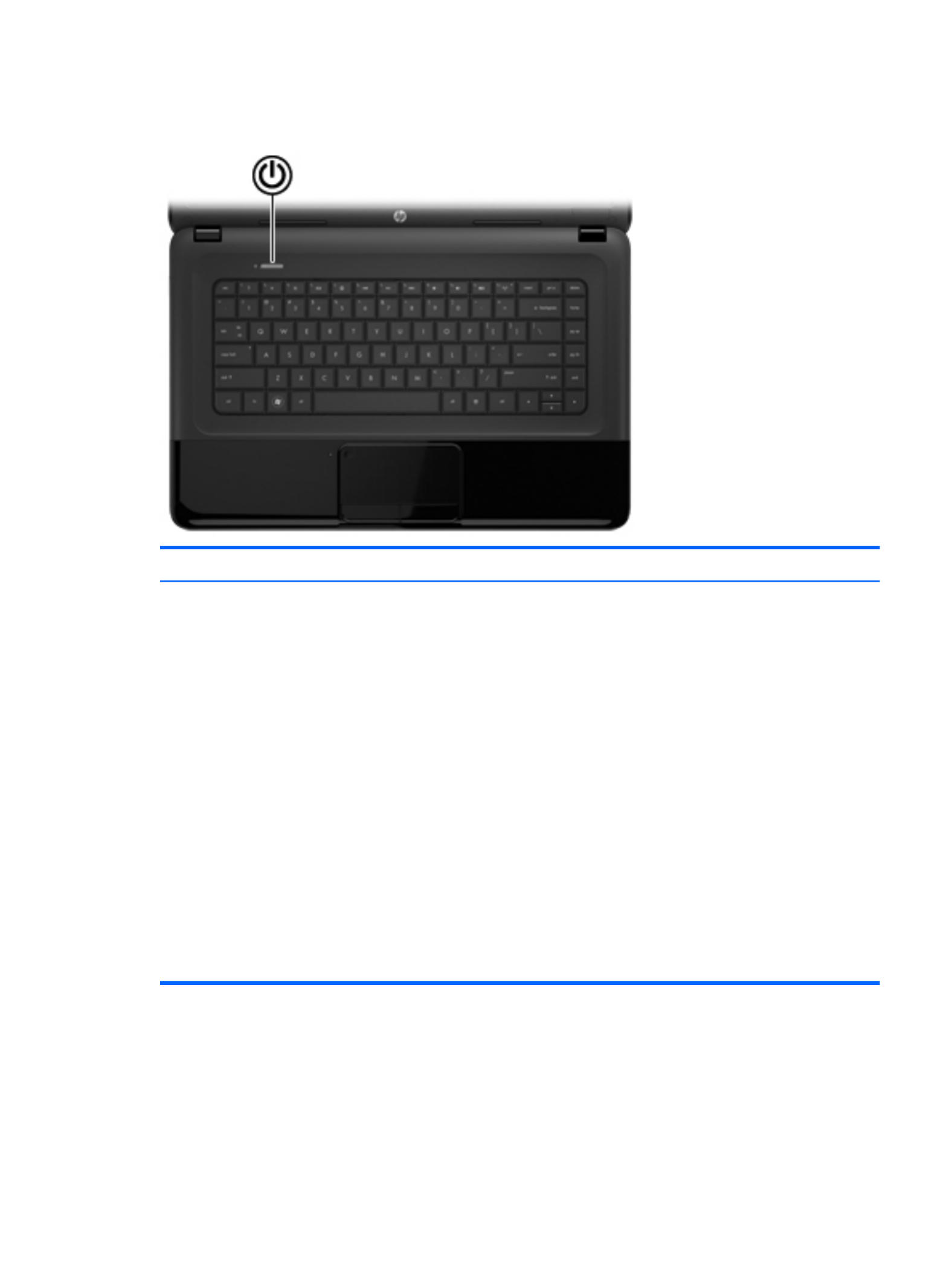
Button
Component Description
Power button ●When the computer is off, press the button to turn on
the computer.
●When the computer is on, press the button briefly to
initiate Sleep.
●When the computer is in the Sleep state, press
the button briefly to exit Sleep.
●When the computer is in Hibernation, press
the button briefly to exit Hibernation.
CAUTION: Pressing and holding down the power
button will result in the loss of unsaved information.
If the computer has stopped responding and Microsoft
Windows shutdown procedures are ineffective, press and
hold the power button down for at least 5 seconds to turn
off the computer.
To learn more about your power settings, select Start >
Control Panel > System and Security > Power
Options.
Button 7

Keys
Item Component Description
(1) esc key Displays system information when pressed in combination
with the fn key.
(2) fn key Used in conjunction with hotkeys.
(3) Windows logo key Displays the Windows Start menu.
(4) Action keys Execute frequently used system functions.
(5) Windows applications key Displays a shortcut menu for items beneath the pointer.
8 Chapter 2 External component identification

Lights
Item Component Description
(1) Caps lock light On: Caps lock is on, which switches the keys to all
capital letters.
(2) Power light ●White: The computer is on.
●Blinking white: The computer is in the Sleep state,
which is an energy-saving mode. The computer
shuts off power to the display and other
unneeded components.
●Off: The computer is off or in Hibernation.
Hibernation is an energy-saving mode that uses the
least amount of power.
(3) Wireless light ●White: An integrated wireless device, such as a
WLAN device and/or a Bluetooth device, is on.
●Amber: All wireless devices are off.
Lights 9

Left side
Item Component Description
(1) External monitor port Connects an external VGA monitor or projector.
(2) Vents (2) Enable airflow to cool internal components.
NOTE: The computer fan starts up automatically to cool
internal components and prevent overheating. It is
normal for the internal fan to cycle on and off during
routine operation.
(3) RJ-45 (network) jack Connects a network cable.
(4) HDMI port Connects an optional video or audio device, such as a
high-definition television, any compatible digital or
audio device.
(5) USB port Connects an optional USB device.
(6) Audio-in (microphone) jack Connects an optional computer headset microphone,
stereo array microphone, or monaural microphone.
(7) Audio-out (headphone) jack Connects optional powered stereo speakers,
headphones, earbuds, a headset, or a television
audio cable.
WARNING! To reduce the risk of personal injury,
adjust the volume before putting on headphones,
earbuds, or a headset. For additional safety information,
refer to the Regulatory, Safety, and Environmental
Notices.
NOTE: When a device is connected to the jack,
the computer speakers are disabled.
Left side 11

Item Component Description
(8) Digital Media slot Supports the following digital card formats:
●Secure Digital (SD) Memory Card
●Secure Digital Extended Capacity (SDxC)
Memory Card
●Secure Digital High Capacity (SDHC) Memory Card
●MultiMediaCard (MMC)
(9) Hard drive light Blinking white: The hard drive is being accessed.
(10) Power light ●White: The computer is on.
●Blinking white: The computer is in the Sleep state,
which is an energy-saving mode. The computer shuts
off power to the display and other
unneeded components.
12 Chapter 2 External component identification

Right side
Item Component Description
(1) Optical drive Reads and writes (select models only) to an optical disk.
(2) Optical drive light ●Green: The optical drive is being accessed.
●Off: The optical drive is idle.
(3) Optical drive eject button Releases the disc tray.
(4) USB port Connects an optional USB device.
CAUTION: While there are multiple USB ports on the
same side, only one USB port will able to support a high
power device at a time.
(5) AC adapter light ●White: The AC adapter is connected and the battery
is charged.
●Amber: The AC adapter is connected and the
battery is charging.
●Off: The computer is using DC power.
(6) Power connector Connects an AC adapter.
(7) Security cable slot Attaches an optional security cable to the computer.
NOTE: The security cable is designed to act as a
deterrent, but it may not prevent the computer from being
mishandled or stolen.
Right side 13

Bottom
Item Component Description
(1) Battery bay Holds the battery.
(2) Vents (4) Enable airflow to cool internal components.
NOTE: The computer fan starts up automatically to cool
internal components and prevent overheating. It is
normal for the internal fan to cycle on and off during
routine operation.
(3) Battery release latch Releases the battery from the battery bay.
(4) Memory module/wireless module
compartment cover
The memory module/wireless module compartment cover
provides access to the memory module compartment,
wireless module compartment, keyboard retention screw,
and optical drive bay.
CAUTION: To prevent an unresponsive system, replace
the wireless module only with a wireless module
authorized for use in the computer by the governmental
agency that regulates wireless devices in your country or
region. If you replace the module and then receive a
warning message, remove the module to restore
computer functionality, and then contact customer support
through Help and Support.
(5) Hard drive compartment cover The hard drive compartment cover provides access to the
hard drive bay and the RTC battery.
14 Chapter 2 External component identification

3 Illustrated parts catalog
15

Computer major components
Item Component Spare part number
(1) Display assembly: The display assembly is spared at the subcomponent level only. For more display assembly
spare part information, see Display assembly subcomponents on page 20.
Computer major components 17

Item Component Spare part number
(2) Keyboard (includes keyboard cable):
For use in Belgium 646125-A41
For use in Bulgaria 646125-261
For use in the Czech Republic 646125-221
For use in Denmark, Finland, and Norway 646125-DH1
For use in France 646125-051
For use in Germany 646125-041
For use in Greece 646125-DJ1
For use in Hungary 646125-211
For use in Israel 646125-BB1
For use in Italy 646125-061
For use in the Netherlands 646125-B31
For use in Portugal 646125-131
For use in Romania 646125-271
For use in Russia 646125-251
For use in Saudi Arabia 646125-171
For use in Slovenia 646125-BA1
For use in Spain 646125-071
For use in Switzerland 646125-BG1
For use in Turkey 646125-141
For use in the United Kingdom and Singapore 646125-031
(3) Top cover (includes the TouchPad board) 686283-001
(4) Power button board (includes cable) 686270-001
(5) TouchPad button board (includes bracket, TouchPad button board cable, and
TouchPad cable)
686271-001
(6) Speakers (include speaker cables) 686279-001
(7) Optical drive connector cable (includes bracket) 686257-001
(8) USB board (includes cable) 686269-001
(9) System board (includes processor and replacement thermal material):
For use on computer models equipped with an AMD E2-1800 processor (1.70-GHz,
1333-MHz, 18 W, dual core, UMA graphics subsystem memory)
688304-001
For use on computer models equipped with an AMD E1-1200 processor (1.40-GHz,
1066-MHz, 18 W, dual core, UMA graphics subsystem memory)
688303-001
18 Chapter 3 Illustrated parts catalog

Display assembly subcomponents
Item Component Spare part number
(1) Display bezel 686255-001
(2) Webcam/microphone module (includes double-sided adhesive) 686285-001
(3) 15.6-in, LED, SVA, HD, BrightView display panel 686273-001
Display Hinge Kit, includes: 686262-001
(4) Left and right display hinge covers
(5) Left and right display hinges and vertical support brackets
20 Chapter 3 Illustrated parts catalog

Mass storage devices
Item Component Spare part number
(1) Hard drive (does not include hard drive bracket, hard drive connector cable, or screws):
640-GB, 5400-rpm, 9.5-mm 669300-001
500-GB, 5400-rpm, 9.5-mm 669299-001
320-GB, 5400-rpm, 9.5-mm 622643-001
Hard Drive Hardware Kit, includes: 686261-001
(2a) Hard drive bracket
(2b) Hard drive connector cable
Hard drive bracket screws (not illustrated)
(3) DVD±RW Double-Layer with SuperMulti Drive (includes optical drive bezel
and optical drive bracket)
686268-001
22 Chapter 3 Illustrated parts catalog

Miscellaneous parts
Component Spare part number
65-W HP Smart AC adapter (RC, V, 3-wire) 609939-001
Power cord (3-pin, black, 1.83-m):
For use in Denmark 490371-081
For use in Europe 490371-021
For use in Israel 490371-BB1
For use in Italy 490371-061
For use in North America 490371-001
For use in South Africa 490371-AR1
For use in Switzerland 490371-111
For use in the United Kingdom and Singapore 490371-031
Screw Kit 686278-001
Miscellaneous parts 23

Sequential part number listing
Spare part number Description
490371-001 Power cord for use in North America (3-pin, black, 1.83-m)
490371-021 Power cord for use in Europe (3-pin, black, 1.83-m)
490371-031 Power cord for use in the United Kingdom and Singapore (3-pin, black, 1.83-m)
490371-061 Power cord for use in Italy (3-pin, black, 1.83-m)
490371-081 Power cord for use in Denmark (3-pin, black, 1.83-m)
490371-111 Power cord for use in Switzerland (3-pin, black, 1.83-m)
490371-AR1 Power cord for use in South Africa (3-pin, black, 1.83-m)
490371-BB1 Power cord for use in Israel (3-pin, black, 1.83-m)
593553-001 6-cell, 47-Wh, 2.20-Ah, Li-ion battery
593554-001 6-cell, 55-Wh, 2.55-Ah, Li-ion battery
609939-001 65-W HP Smart AC adapter (RC, V, 3-wire)
622643-001 320-GB, 5400-rpm, 9.5-mm hard drive (does not include hard drive bracket, hard drive connector
cable, or screws)
NOTE: The hard drive bracket, hard drive connector included in the Hardcable, and screws are
Drive Hardware Kit, spare part number 686261-001.
641369-001 4-GB memory module (PC3, 12800, 1600-MHz)
646125-031 Keyboard for use in the United Kingdom and Singapore (includes keyboard cable)
646125-041 Keyboard for use in Germany (includes keyboard cable)
646125-051 Keyboard for use in France (includes keyboard cable)
646125-061 Keyboard for use in Italy (includes keyboard cable)
646125-071 Keyboard for use in Spain (includes keyboard cable)
646125-131 Keyboard for use in Portugal (includes keyboard cable)
646125-141 Keyboard for use in Turkey (includes keyboard cable)
646125-171 Keyboard for use in Saudi Arabia (includes keyboard cable)
646125-211 Keyboard for use in Hungary (includes keyboard cable)
646125-221 Keyboard for use in the Czech Republic (includes keyboard cable)
646125-251 Keyboard for use in Russia (includes keyboard cable)
646125-261 Keyboard for use in Bulgaria (includes keyboard cable)
646125-271 Keyboard for use in Romania (includes keyboard cable)
646125-A41 Keyboard for use in Belgium (includes keyboard cable)
646125-B31 Keyboard for use in the Netherlands (includes keyboard cable)
24 Chapter 3 Illustrated parts catalog

Spare part number Description
686273-001 15.6-in, LED, SVA, HD, BrightView display panel
686274-001 RTC battery
686276-001 Rubber Kit (includes front and rear rubber feet, display bezel rubber bumpers, and display bezel
rubber screw covers)
686278-001 Screw Kit
686279-001 Speakers (include speaker cables
686283-001 Top cover (includes the TouchPad board)
686285-001 Webcam/microphone module (includes double-sided adhesive)
688303-001 System board for use on computer models equipped with an AMD E1-1200 processor (1.40-GHz,
1066-MHz, 18 W, dual core, UMA graphics subsystem memory; includes processor and
replacement thermal material)
688304-001 System board for use on computer models equipped with an AMD E2-1800 processor (1.70-GHz,
1333-MHz, 18 W, dual core, UMA graphics subsystem memory; includes processor and
replacement thermal material)
688305-001 System board for use on computer models equipped with an AMD E-300 processor (1.30-GHz,
1066-MHz, 18 W, dual core, UMA graphics subsystem memory; includes processor and
replacement thermal material)
688306-001 Fan/heat sink assembly (includes replacement thermal material)
690019-001 Atheros AR9565 802.11b/g/n 1×1 WiFi + Bluetooth 4.0 Combo Adapter
690020-001 Ralink RT3290LE 802.11b/g/n 1×1 WiFi and Bluetooth 4.0 Combo Adapter
691415-001 Ralink RT5390R 802.11bg/n 1×1 WiFi Adapter
26 Chapter 3 Illustrated parts catalog

4 Removal and replacement
procedures
Preliminary replacement requirements
Tools required
You will need the following tools to complete the removal and replacement procedures:
●Flat-bladed screwdriver
●Magnetic screwdriver
●Phillips P0 and P1 screwdrivers
Service considerations
The following sections include some of the considerations that you must keep in mind during
disassembly and assembly procedures.
NOTE: As you remove each subassembly from the computer, place the subassembly (and all
accompanying screws) away from the work area to prevent damage.
Plastic parts
CAUTION: Using excessive force during disassembly and reassembly can damage plastic parts. Use
care when handling the plastic parts. Apply pressure only at the points designated in
the maintenance instructions.
Cables and connectors
CAUTION: When servicing the computer, be sure that cables are placed in their proper locations
during the reassembly process. Improper cable placement can damage the computer.
Cables must be handled with extreme care to avoid damage. Apply only the tension required to unseat
or seat the cables during removal and insertion. Handle cables by the connector whenever possible. In
all cases, avoid bending, twisting, or tearing cables. Be sure that cables are routed in such a way that
they cannot be caught or snagged by parts being removed or replaced. Handle flex cables with
extreme care; these cables tear easily.
Preliminary replacement requirements 27

Drive handling
CAUTION: Drives are fragile components that must be handled with care. To prevent damage to
the computer, damage to a drive, or loss of information, observe these precautions:
Before removing or inserting a hard drive, shut down the computer. If you are unsure whether
the computer is off or in Hibernation, turn the computer on, and then shut it down through
the operating system.
Before handling a drive, be sure that you are discharged of static electricity. While handling a drive,
avoid touching the connector.
Before removing a diskette drive or optical drive, be sure that a diskette or disc is not in the drive and
be sure that the optical drive tray is closed.
Handle drives on surfaces covered with at least one inch of shock-proof foam.
Avoid dropping drives from any height onto any surface.
After removing a hard drive, an optical drive, or a diskette drive, place it in a static-proof bag.
Avoid exposing an internal hard drive to products that have magnetic fields, such as monitors
or speakers.
Avoid exposing a drive to temperature extremes or liquids.
If a drive must be mailed, place the drive in a bubble pack mailer or other suitable form of protective
packaging and label the package “FRAGILE.”
Grounding guidelines
Electrostatic discharge damage
Electronic components are sensitive to electrostatic discharge (ESD). Circuitry design and structure
determine the degree of sensitivity. Networks built into many integrated circuits provide some
protection, but in many cases, ESD contains enough power to alter device parameters or melt
silicon junctions.
A discharge of static electricity from a finger or other conductor can destroy static-sensitive devices or
microcircuitry. Even if the spark is neither felt nor heard, damage may have occurred.
An electronic device exposed to ESD may not be affected at all and can work perfectly throughout a
normal cycle. Or the device may function normally for a while, then degrade in the internal layers,
reducing its life expectancy.
28 Chapter 4 Removal and replacement procedures

CAUTION: To prevent damage to the computer when you are removing or installing internal
components, observe these precautions:
Keep components in their electrostatic-safe containers until you are ready to install them.
Before touching an electronic component, discharge static electricity by using the guidelines described
in this section.
Avoid touching pins, leads, and circuitry. Handle electronic components as little as possible.
If you remove a component, place it in an electrostatic-safe container.
The following table shows how humidity affects the electrostatic voltage levels generated by
different activities.
CAUTION: A product can be degraded by as little as 700 V.
Typical electrostatic voltage levels
Relative humidity
Event 10% 40% 55%
Walking across carpet 35,000 V 15,000 V 7,500 V
Walking across vinyl floor 12,000 V 5,000 V 3,000 V
Motions of bench worker 6,000 V 800 V 400 V
Removing DIPS from plastic tube 2,000 V 700 V 400 V
Removing DIPS from vinyl tray 11,500 V 4,000 V 2,000 V
Removing DIPS from Styrofoam 14,500 V 5,000 V 3,500 V
Removing bubble pack from PCB 26,500 V 20,000 V 7,000 V
Packing PCBs in foam-lined box 21,000 V 11,000 V 5,000 V
Preliminary replacement requirements 29

Packaging and transporting guidelines
Follow these grounding guidelines when packaging and transporting equipment:
●To avoid hand contact, transport products in static-safe tubes, bags, or boxes.
●Protect ESD-sensitive parts and assemblies with conductive or approved containers or packaging.
●Keep ESD-sensitive parts in their containers until the parts arrive at static-free workstations.
●Place items on a grounded surface before removing items from their containers.
●Always be properly grounded when touching a component or assembly.
●Store reusable ESD-sensitive parts from assemblies in protective packaging or
nonconductive foam.
●Use transporters and conveyors made of antistatic belts and roller bushings. Be sure that
mechanized equipment used for moving materials is wired to ground and that proper materials
are selected to avoid static charging. When grounding is not possible, use an ionizer to dissipate
electric charges.
Workstation guidelines
Follow these grounding workstation guidelines:
●Cover the workstation with approved static-shielding material.
●Use a wrist strap connected to a properly grounded work surface and use properly grounded tools
and equipment.
●Use conductive field service tools, such as cutters, screwdrivers, and vacuums.
●When fixtures must directly contact dissipative surfaces, use fixtures made only of static-
safe materials.
●Keep the work area free of nonconductive materials, such as ordinary plastic assembly aids
and Styrofoam.
●Handle ESD-sensitive components, parts, and assemblies by the case or PCM laminate. Handle
these items only at static-free workstations.
●Avoid contact with pins, leads, or circuitry.
●Turn off power and input signals before inserting or removing connectors or test equipment.
30 Chapter 4 Removal and replacement procedures

Equipment guidelines
Grounding equipment must include either a wrist strap or a foot strap at a grounded workstation.
●When seated, wear a wrist strap connected to a grounded system. Wrist straps are flexible straps
with a minimum of one megohm ±10% resistance in the ground cords. To provide proper ground,
wear a strap snugly against the skin at all times. On grounded mats with banana-plug connectors,
use alligator clips to connect a wrist strap.
●When standing, use foot straps and a grounded floor mat. Foot straps (heel, toe, or boot straps)
can be used at standing workstations and are compatible with most types of shoes or boots. On
conductive floors or dissipative floor mats, use foot straps on both feet with a minimum of one
megohm resistance between the operator and ground. To be effective, the conductive must be
worn in contact with the skin.
The following grounding equipment is recommended to prevent electrostatic damage:
●Antistatic tape
●Antistatic smocks, aprons, and sleeve protectors
●Conductive bins and other assembly or soldering aids
●Nonconductive foam
●Conductive tabletop workstations with ground cords of one megohm resistance
●Static-dissipative tables or floor mats with hard ties to the ground
●Field service kits
●Static awareness labels
●Material-handling packages
●Nonconductive plastic bags, tubes, or boxes
●Metal tote boxes
●Electrostatic voltage levels and protective materials
The following table lists the shielding protection provided by antistatic bags and floor mats.
Material Use Voltage protection level
Antistatic plastics Bags 1,500 V
Carbon-loaded plastic Floor mats 7,500 V
Metallized laminate Floor mats 5,000 V
Preliminary replacement requirements 31

Component replacement procedures
This chapter provides removal and replacement procedures.
There are as many as 72 screws that must be removed, replaced, and/or loosened when servicing
the computer. Make special note of each screw size and location during removal and replacement.
Service tag
When ordering parts or requesting information, provide the computer serial number and model number
provided on the service tag. It is necessary to remove the battery to obtain these numbers. See Battery
on page 34 for battery removal instructions.
Item Component Description
(1) Product name This is the product name affixed to the front of
the computer.
(2) Serial number (s/n) This is an alphanumeric identifier that is unique to
each product.
(3) Part number/Product number (p/n) This number provides specific information about
the product’s hardware components. The part number
helps a service technician determine what components
and parts are needed.
32 Chapter 4 Removal and replacement procedures
Item Component Description
(4) Warranty period This number describes the duration of the warranty
period for the computer.
(5) Model description This is the alphanumeric identifier used to locate
documents, drivers, and support for the computer.
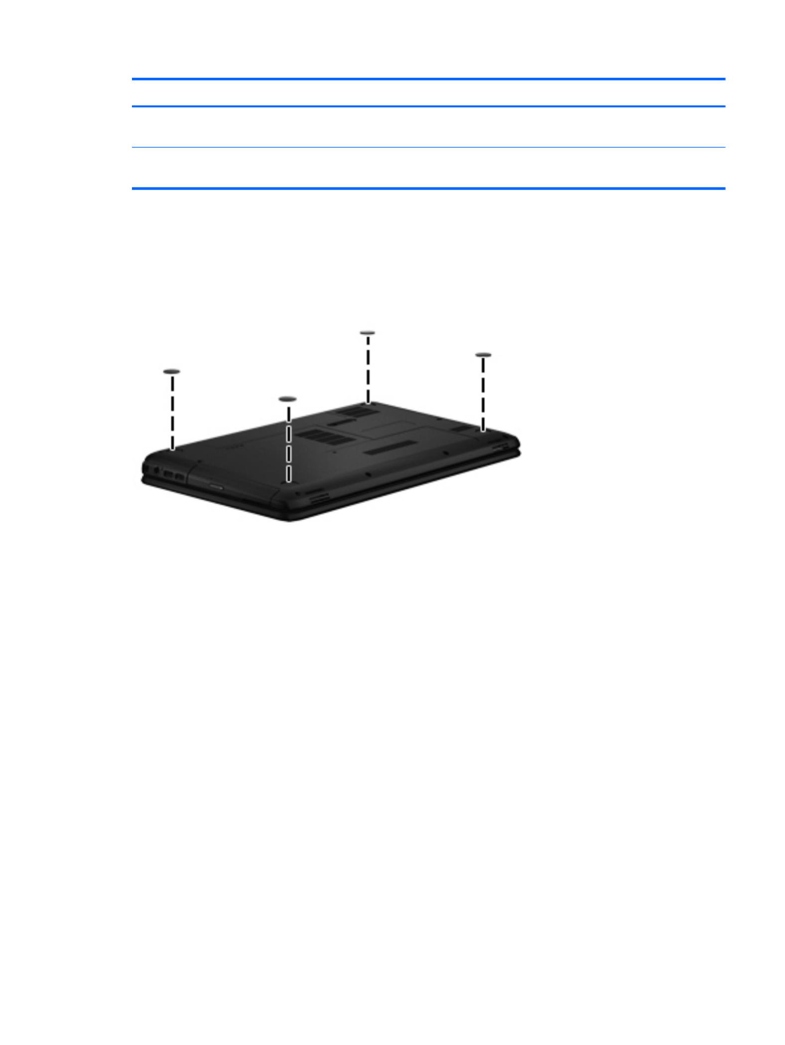
Computer feet
The computer feet are adhesive-backed rubber pads. There are 4 rubber feet that attach to
the base enclosure, as indicated in the illustration below. These rubber feet are available in the Rubber
Kit, spare part number 686276-001.
Component replacement procedures 33

Battery
Description Spare part number
6-cell, 55-Wh, 2.55-Ah, Li-ion battery 593554-001
6-cell, 47-Wh, 2.20-Ah, Li-ion battery 593553-001
IMPORTANT: The customer should not attempt to replace the computer battery, which is installed
and sealed at the factory. A broken battery seal voids the computer and battery warranties. The
computer has an internal rechargeable battery that can be replaced only by an authorized service
provider.
Before disassembling the computer, follow these steps:
1. Turn off the computer. If you are unsure whether the computer is off or in Hibernation, turn
the computer on, and then shut it down through the operating system.
2. Disconnect the power from the computer by unplugging the power cord from the computer.
3. Disconnect all external devices from the computer.
Remove the battery:
1. Turn the computer upside down on a flat surface.
2. Slide the battery release latch (1) to release the battery.
3. Pivot the front edge of the battery (2) up and back.
4. Remove the battery (3) from the computer.
To insert the battery:
1. Align the tabs on the rear edge of the battery with the notches on the rear edge of the battery bay.
2. Pivot the front edge of the battery down into the battery bay until it is seated. (The battery release
latch will automatically lock into place.)
34 Chapter 4 Removal and replacement procedures
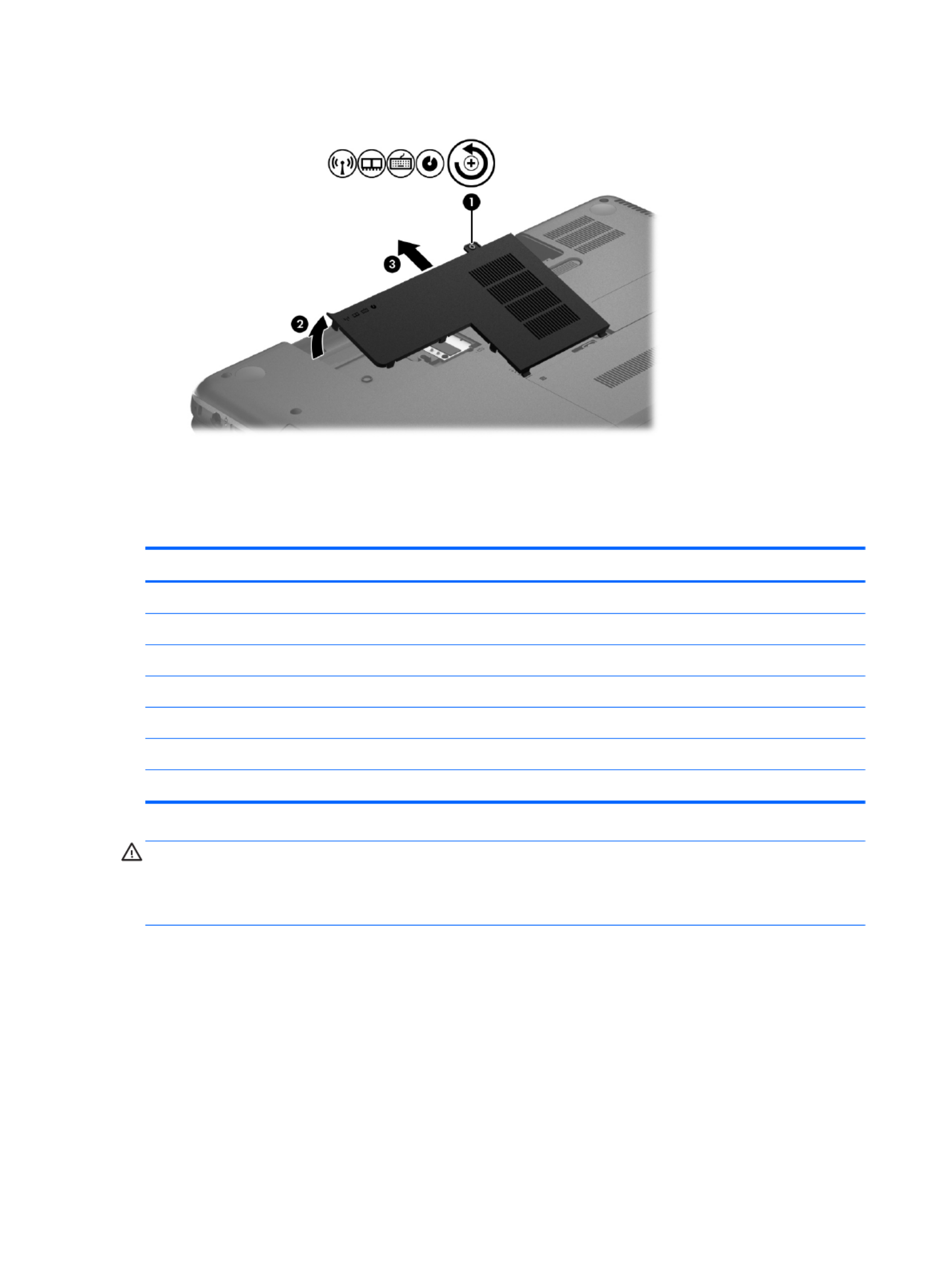
5. Remove the memory module (2) by pulling it away from the slot at an angle.
Reverse this procedure to install a memory module.
WLAN module
Description Spare part number
Atheros AR9565 802.11b/g/n 1×1 WiFi + BT4.0 Combo Adapter 690019-001
Atheros HB125 802.11b/g/n 1×1 WLAN module 675794-001
Atheros 9485GN 802.11b/g/n 1×1 WiFi and 3012 Bluetooth 4.0 Combo Adapter 655795-001
Broadcom 4313GN 802.11b/g/n 1×1 WiFi and 20702 Bluetooth 4.0 Combo Adapter 657325-001
Ralink RT5390F 802.11b/g/n 1×1 WLAN module 670691-001
Ralink RT5390R 802.11bg/n 1×1 WiFi Adapter 691415-001
Ralink RT3290LE 802.11b/g/n 1×1 WiFi and Bluetooth 4.0 Combo Adapter 690020-001
CAUTION: To prevent an unresponsive system, replace the wireless module only with a wireless
module authorized for use in the computer by the governmental agency that regulates wireless devices
in your country or region. If you replace the module and then receive a warning message, remove the
module to restore device functionality, and then contact technical support.
Before removing the WLAN module, follow these steps:
1. Turn off the computer. If you are unsure whether the computer is off or in Hibernation, turn
the computer on, and then shut it down through the operating system.
2. Disconnect the power from the computer by unplugging the power cord from the computer.
3. Disconnect all external devices from the computer.
36 Chapter 4 Removal and replacement procedures

4. Remove the battery (see Battery on page 34).
5. Remove the memory module/wireless module compartment cover (see Memory module
on page 35).
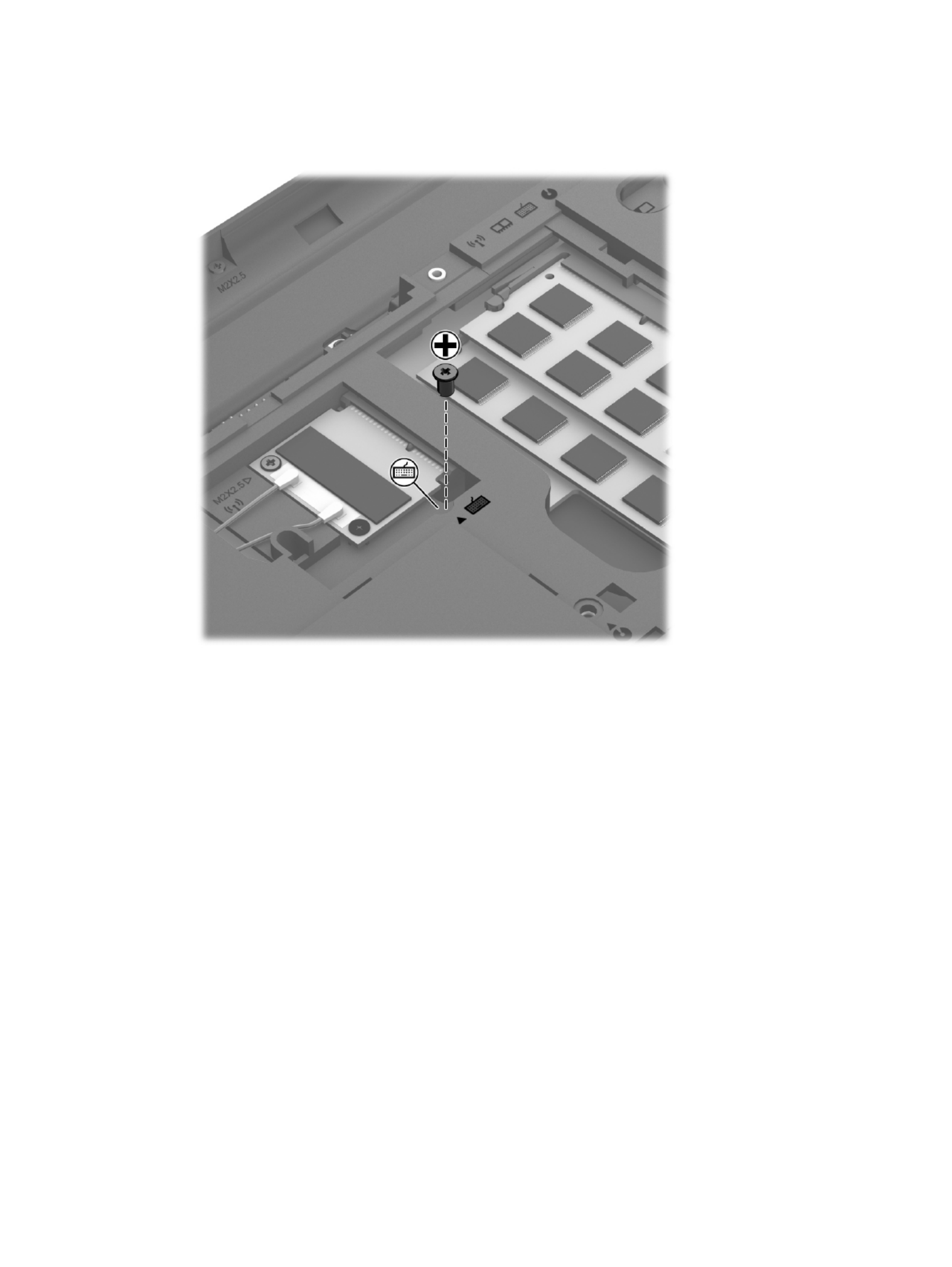
Remove the WLAN module:
1. Disconnect the WLAN antenna cables (1) from the terminals on the WLAN module.
NOTE: The #1 WLAN antenna cable is connected to the WLAN module #1 terminal. The #2
WLAN antenna cable is connected to the WLAN module #2 terminal.
2. Remove the Phillips PM2.0×3.0 screw (2) that secures the WLAN module to the system board.
(The WLAN module tilts up.)
3. Remove the WLAN module by pulling the module away from the slot at an angle (3).
NOTE: If the WLAN antennas are not connected to the terminals on the WLAN module,
the protective sleeves must be installed on the antenna connectors, as shown in the
following illustration.
Component replacement procedures 37

Reverse this procedure to install the WLAN module.
Keyboard
NOTE: The keyboard spare part kit includes the keyboard cable.
For use in country/region Spare part number For use in country/region Spare part number
For use in Belgium 646125-A41 For use in the Netherlands 646125-B31
For use in Bulgaria 646125-261 For use in Portugal 646125-131
For use in the Czech Republic 646125-221 For use in Romania 646125-271
For use in Denmark, Finland,
and Norway
646125-DH1 For use in Russia 646125-251
For use in France 646125-051 For use in Saudi Arabia 646125-171
For use in Germany 646125-041 For use in Slovenia 646125-BA1
For use in Greece 646125-DJ1 For use in Spain 646125-071
For use in Hungary 646125-211 For use in Switzerland 646125-BG1
For use in Israel 646125-BB1 For use in Turkey 646125-141
For use in Italy 646125-061 For use in the United Kingdom
and Singapore
646125-031
Before removing the keyboard, follow these steps:
1. Turn off the computer. If you are unsure whether the computer is off or in Hibernation, turn
the computer on, and then shut it down through the operating system.
2. Disconnect the power from the computer by unplugging the power cord from the computer.
3. Disconnect all external devices from the computer.
4. Remove the battery (see Battery on page 34).
5. Remove the memory module/wireless module compartment cover (see Memory module
on page 35).
38 Chapter 4 Removal and replacement procedures
Remove the keyboard:
1. Remove the Phillips PM2.5×4.0 screw that secures the keyboard to the computer.
2. Rest and secure the computer on its left side.
3. Partially open the computer.
Component replacement procedures 39

4. Insert a screw driver or similar thin tool into the keyboard release hole, and then press on the back
of the keyboard until the keyboard disengages from the computer.
5. Turn the computer right-side up with the front toward you.
6. Lift the rear edge of the keyboard (1) (2), and then swing the keyboard up and forward until it
rests upside down on the palm rest.
40 Chapter 4 Removal and replacement procedures
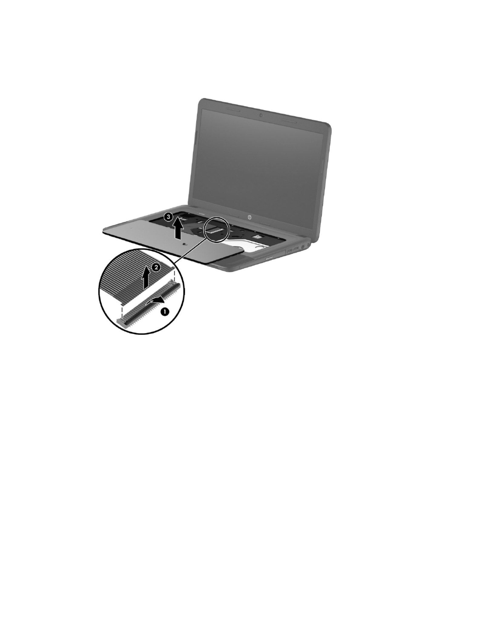
7. Release the zero insertion force (ZIF) connector (1) to which the keyboard cable is attached, and
then disconnect the keyboard cable (2) from the system board.
8. Remove the keyboard (3).
Reverse this procedure to install the keyboard.
Component replacement procedures 41

Optical drive
Description Spare part number
DVD±RW Double-Layer with SuperMulti Drive (includes optical drive bezel and optical
drive bracket)
686268-001
Before removing the optical drive, follow these steps:
1. Turn off the computer. If you are unsure whether the computer is off or in Hibernation, turn
the computer on, and then shut it down through the operating system.
2. Disconnect the power from the computer by unplugging the power cord from the computer.
3. Disconnect all external devices from the computer.
4. Remove the battery (see Battery on page 34).
5. Remove the memory module/wireless module compartment cover (see Memory module
on page 35).
Remove the optical drive:
1. Remove the Phillips PM2.5×4.0 screw (1) that secures the optical drive to the computer.
2. Use a flat-blade screw driver or similar tool to press on the optical drive bracket tab (2) to release
the optical drive.
3. Remove the optical drive (3) from the computer.
42 Chapter 4 Removal and replacement procedures

4. If it is necessary to replace the optical drive bezel, use a thin tool or an unbent paper clip (1) to
release the optical drive tray.
5. Use a flat-blade screw driver or similar tool to press on the optical drive bezel tab (2) to release
the optical drive bezel.
6. Release the left side of the optical drive bezel (3).
7. Remove the optical drive bezel (4).
8. If it is necessary to replace the optical drive bracket, position the optical drive with the rear panel
toward you.
9. Remove the two Phillips PM2.0×3.0 screws (1) that secure the optical drive bracket to the
optical drive.
10. Remove the optical drive bracket (2).
Reverse this procedure to install the optical drive.
Component replacement procedures 43

Hard drive
NOTE: The hard drive spare part kit does not include the hard drive bracket, hard drive connector
cable, or screws.
Description Spare part number
640-GB, 5400-rpm, 9.5-mm 669300-001
500-GB, 5400-rpm, 9.5-mm 669299-001
320-GB, 5400-rpm, 9.5-mm 622643-001
Hard Drive Hardware Kit (includes hard drive bracket, hard drive connector cable, and screws) 686261-001
Before removing the hard drive, follow these steps:
1. Turn off the computer. If you are unsure whether the computer is off or in Hibernation, turn
the computer on, and then shut it down through the operating system.
2. Disconnect the power from the computer by unplugging the power cord from the computer.
3. Disconnect all external devices from the computer.
4. Remove the battery (see Battery on page 34).
5. Remove the memory module/wireless module compartment cover (see Memory module
on page 35).
Remove the hard drive:
1. Loosen the captive screw (1) that secures the hard drive compartment cover to the computer.
2. Lift the rear edge of the hard drive compartment cover (2) up and forward until it rests at
an angle.
44 Chapter 4 Removal and replacement procedures

3. Remove the hard drive compartment cover (3) by sliding it away from the computer at an angle.
The hard drive compartment cover is available in the Cover Kit, spare part number 686272-001.
4. Disconnect the hard drive connector cable (1) from the system board, and then release the cable
from the clip (2) built into the base enclosure.
5. Remove the four Phillips PM2.5×4.0 screws (3) that secure the hard drive to the computer.
6. Remove the hard drive (4) from the hard drive bay.
Component replacement procedures 45
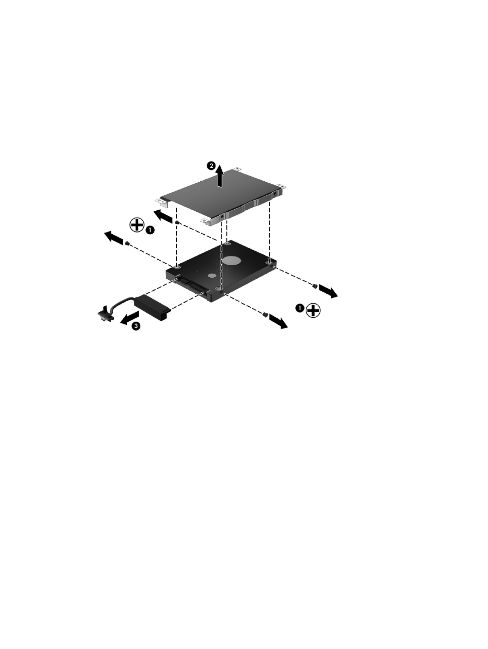
7. If it is necessary to disassemble the hard drive, perform the following steps:
a. Remove the four Phillips PM3.0×3.0 screws (1) that secure the hard drive bracket to the
hard drive.
b. Remove the hard drive bracket (2) from the hard drive.
c. Disconnect the hard drive connector cable (3) from the hard drive. The hard drive bracket,
hard drive connector cable, and screws are available in the Hard Drive Hardware Kit, spare
part number 686261-001.
Reverse this procedure to reassemble and install the hard drive.
46 Chapter 4 Removal and replacement procedures

RTC battery
Description Spare part number
RTC battery 686274-001
Before removing the RTC battery, follow these steps:
1. Turn off the computer. If you are unsure whether the computer is off or in Hibernation, turn
the computer on, and then shut it down through the operating system.
2. Disconnect the power from the computer by unplugging the power cord from the computer.
3. Disconnect all external devices from the computer.
4. Remove the battery (see Battery on page 34).
5. Remove the memory module/wireless module compartment cover (see Memory module
on page 35).
6. Remove the hard drive compartment cover (see Hard drive on page 44).
Remove the RTC battery:
1. Use a flat-bladed, non-metallic tool (1) to release the RTC battery from the socket on the
system board.
2. Remove the RTC battery (2).
Component replacement procedures 47

Reverse this procedure to install the RTC battery. When installing the RTC battery, make sure the “+”
sign faces up.
Top cover
Description Spare part number
Top cover (includes the TouchPad board) 686283-001
Before removing the top cover, follow these steps:
1. Turn off the computer. If you are unsure whether the computer is off or in Hibernation, turn
the computer on, and then shut it down through the operating system.
2. Disconnect the power from the computer by unplugging the power cord from the computer.
3. Disconnect all external devices from the computer.
4. Remove the battery (see Battery on page 34), and then remove the following components:
a. Memory module/wireless module compartment cover (see Memory module on page 35)
b. Keyboard (see Keyboard on page 38)
c. Hard drive (see Hard drive on page 44)
NOTE: When replacing the top cover, be sure to remove the following components from the defective
top cover and install them on the replacement top cover:
●Power button board (see Power button board on page 51)
●TouchPad button board (see TouchPad button board on page 52)
Remove the top cover:
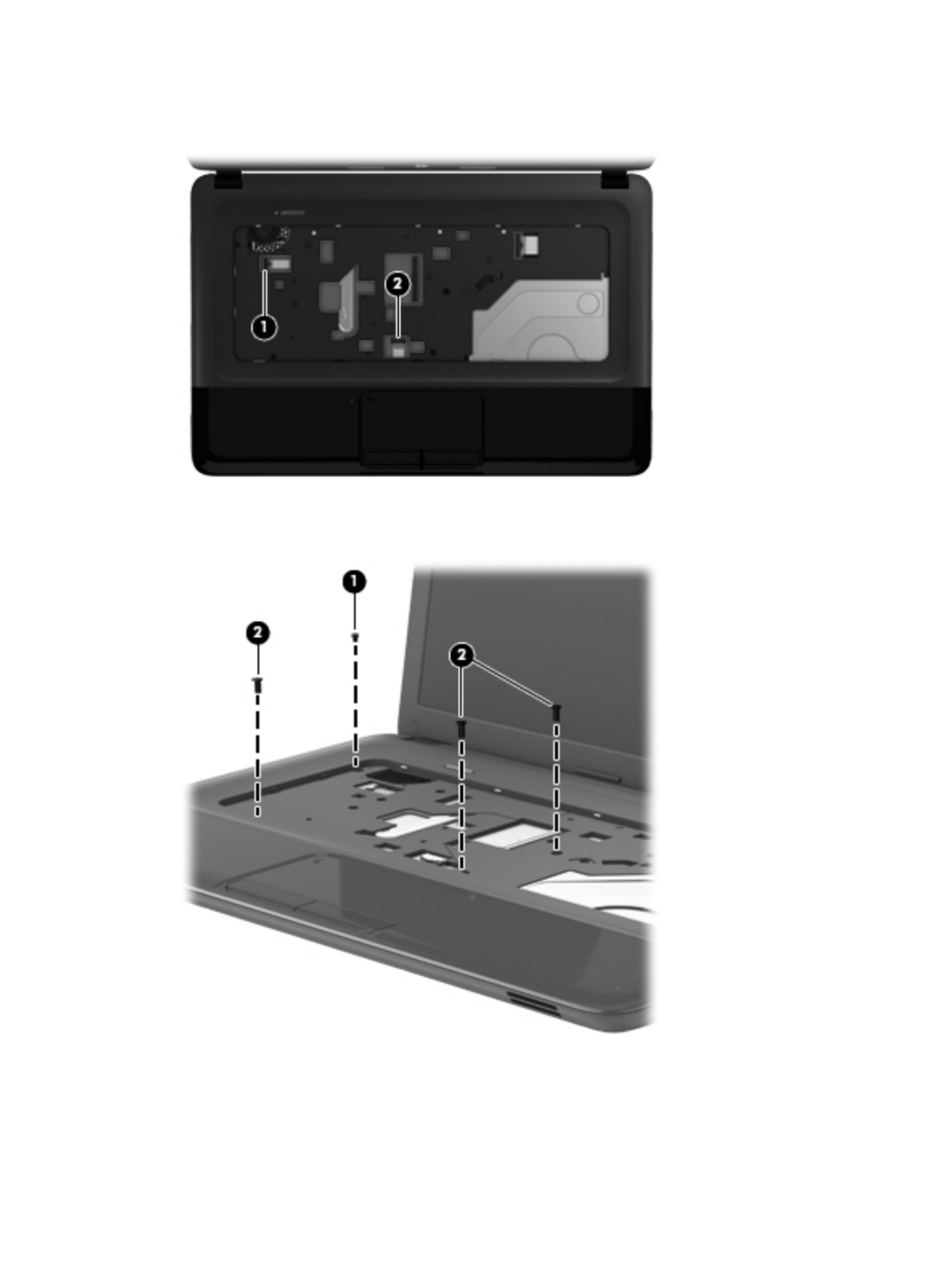
1. Remove the six Phillips PM2.5×6.5 screws (1) (2) and the two Phillips PM2.5×10.0 screws that
secure the top cover to the computer.
48 Chapter 4 Removal and replacement procedures

2. Remove the four Phillips PM2.0×2.5 screws on the rear edge of the battery bay and in the hard
drive bay that secure the top cover to the computer.
3. Remove the four Phillips PM2.5×4.0 screws on the front edge of the battery bay and near the hard
drive connector that secure the top cover to the computer.
4. Turn the computer right side up, with the front toward you.
5. Open the computer.
6. Release the ZIF connector to which the power button board cable is connected, and then
disconnect the power button board cable (1) from the system board.
Component replacement procedures 49
7. Release the ZIF connector to which the TouchPad button board cable is connected, and then
disconnect the TouchPad button board cable (2) from the system board.
8. Remove the Phillips PM2.0×2.5 screw (1) and the three Phillips PM2.5×6.5 screws (2) that secure
the top cover to the computer.
9. Lift the rear edge of the top cover (1) and swing it up and forward until the left and right sides of
the top cover detach from the base enclosure.
50 Chapter 4 Removal and replacement procedures

10. Remove the top cover (2).
Reverse this procedure to install the top cover.
Power button board
Description Spare part number
Power button board (includes cable) 686270-001
Before removing the power button board, follow these steps:
1. Turn off the computer. If you are unsure whether the computer is off or in Hibernation, turn
the computer on, and then shut it down through the operating system.
2. Disconnect the power from the computer by unplugging the power cord from the computer.
3. Disconnect all external devices from the computer.
4. Remove the battery (see Battery on page 34), and then remove the following components:
a. Memory module/wireless module compartment cover (see Memory module on page 35)
b. Keyboard (see Keyboard on page 38)
c. Hard drive (see Hard drive on page 44)
d. Top cover (see Top cover on page 48)
Remove the power button board:
1. Turn the top cover upside down, with the front toward you.
2. Remove the two Phillips PM2.0×3.0 screws (1) that secure the power button board to
the top cover.
Component replacement procedures 51

3. Remove the power button board (2).
Reverse this procedure to install the power button board.
TouchPad button board
Description Spare part number
TouchPad button board (includes bracket, TouchPad button board cable, and TouchPad cable) 686271-001
Before removing the TouchPad button board, follow these steps:
1. Turn off the computer. If you are unsure whether the computer is off or in Hibernation, turn
the computer on, and then shut it down through the operating system.
2. Disconnect the power from the computer by unplugging the power cord from the computer.
3. Disconnect all external devices from the computer.
4. Remove the battery (see Battery on page 34), and then remove the following components:
a. Memory module/wireless module compartment cover (see Memory module on page 35)
b. Keyboard (see Keyboard on page 38)
c. Hard drive (see Hard drive on page 44)
d. Top cover (see Top cover on page 48)
52 Chapter 4 Removal and replacement procedures

Remove the TouchPad button board:
1. Turn the top cover upside down, with the front toward you.
2. Detach the TouchPad button board cable (1) from the TouchPad. (The TouchPad button board
cable is attached to the TouchPad with double-sided tape).
3. Release the ZIF connector to which the TouchPad board cable is connected, and then disconnect
the TouchPad board cable (2) from the TouchPad board.
4. Release the two pieces of shielding tape that cover the left and right sides of the TouchPad button
board (3).
5. Remove the two Phillips PM2.5×4.0 screws (1) that secure the TouchPad button board to the top
cover. Lift the rear edge of the TouchPad button board (2) until it rests at an angle.
Component replacement procedures 53

6. Remove the TouchPad button board (3) by sliding it away from the top cover at an angle.
Reverse this procedure to install the TouchPad button board.
54 Chapter 4 Removal and replacement procedures

Optical drive connector cable
Description Spare part number
Optical drive connector cable 686257-001
Before removing the optical drive connector cable, follow these steps:
1. Turn off the computer. If you are unsure whether the computer is off or in Hibernation, turn
the computer on, and then shut it down through the operating system.
2. Disconnect the power from the computer by unplugging the power cord from the computer.
3. Disconnect all external devices from the computer.
4. Remove the battery (see Battery on page 34), and then remove the following components:
a. Memory module/wireless module compartment cover (see Memory module on page 35)
b. Keyboard (see Keyboard on page 38)
c. Hard drive (see Hard drive on page 44)
d. Top cover (see Top cover on page 48)
Remove the optical drive connector cable:
1. Disconnect the optical drive connector cable (1) from the system board.
2. Release the optical drive connector cable from the clips (2) and routing channel built into
the base enclosure.
3. Remove the two Phillips PM2.0×4.5 screws (3) that secure the optical drive connector to
the base enclosure.
Component replacement procedures 55
4. Remove the optical drive connector cable (4).
Reverse this procedure to install the optical drive connector cable.
56 Chapter 4 Removal and replacement procedures

Speakers
Description Spare part number
Speakers (include speaker cables) 686279-001
Before removing the speakers, follow these steps:
1. Turn off the computer. If you are unsure whether the computer is off or in Hibernation, turn
the computer on, and then shut it down through the operating system.
2. Disconnect the power from the computer by unplugging the power cord from the computer.
3. Disconnect all external devices from the computer.
4. Remove the battery (see Battery on page 34), and then remove the following components:
a. Memory module/wireless module compartment cover (see Memory module on page 35)
b. Keyboard (see Keyboard on page 38)
c. Hard drive (see Hard drive on page 44)
d. Top cover (see Top cover on page 48)
Remove the speakers:
1. Disconnect the speaker cable (1) from the system board.
2. Release the speaker cable from the clips (2) and routing channel built into the base enclosure.
3. Remove the two Phillips PM2.5×4.0 screws (3) that secure the speakers to the base enclosure.
Component replacement procedures 57
4. Remove the speakers (4).
Reverse this procedure to install the speakers.
58 Chapter 4 Removal and replacement procedures

USB board
Description Spare part number
USB board (includes cable) 686269-001
Before removing the USB board, follow these steps:
1. Turn off the computer. If you are unsure whether the computer is off or in Hibernation, turn
the computer on, and then shut it down through the operating system.
2. Disconnect the power from the computer by unplugging the power cord from the computer.
3. Disconnect all external devices from the computer.
4. Remove the battery (see Battery on page 34), and then remove the following components:
a. Memory module/wireless module compartment cover (see Memory module on page 35)
b. Keyboard (see Keyboard on page 38)
c. Hard drive (see Hard drive on page 44)
d. Top cover (see Top cover on page 48)
Remove the USB board:
1. Release the ZIF connector to which the USB board cable is connected, and then disconnect
the USB board cable (1) from the system board.
2. Remove the Phillips PM2.5×6.0 screw (2) that secures the USB board to the base enclosure.
Component replacement procedures 59

3. Remove the USB board (3).
Reverse this procedure to install the USB board.
60 Chapter 4 Removal and replacement procedures

System board
NOTE: The system board spare part kit includes the processor and replacement thermal material.
Description Spare part number
For use on computer models equipped with an AMD E2-1800 processor (1.70-GHz, 1333-MHz,
18 W, dual core, UMA graphics subsystem memory)
688304-001
For use on computer models equipped with an AMD E1-1200 processor (1.40-GHz, 1066-MHz,
18 W, dual core, UMA graphics subsystem memory)
688303-001
For use on computer models equipped with an AMD E-300 processor (1.30-GHz, 1066-MHz, 18
W, dual core, UMA graphics subsystem memory)
688305-001
Before removing the system board, follow these steps:
1. Turn off the computer. If you are unsure whether the computer is off or in Hibernation, turn
the computer on, and then shut it down through the operating system.
2. Disconnect the power from the computer by unplugging the power cord from the computer.
3. Disconnect all external devices from the computer.
4. Remove the battery (see Battery on page 34), and then remove the following components:
a. Memory module/wireless module compartment cover (see Memory module on page 35)
b. WLAN module (see WLAN module on page 36)
c. Keyboard (see Keyboard on page 38)
d. Optical drive (see Optical drive on page 42)
e. Hard drive (see Hard drive on page 44)
f. Top cover (see Top cover on page 48)
When replacing the system board, be sure that the following components are removed from
the defective system board and installed on the replacement system board:
●Memory module (see Memory module on page 35)
●RTC battery (see RTC battery on page 47)
●Fan/heat sink assembly (see Fan/heat sink assembly on page 63)
Component replacement procedures 61
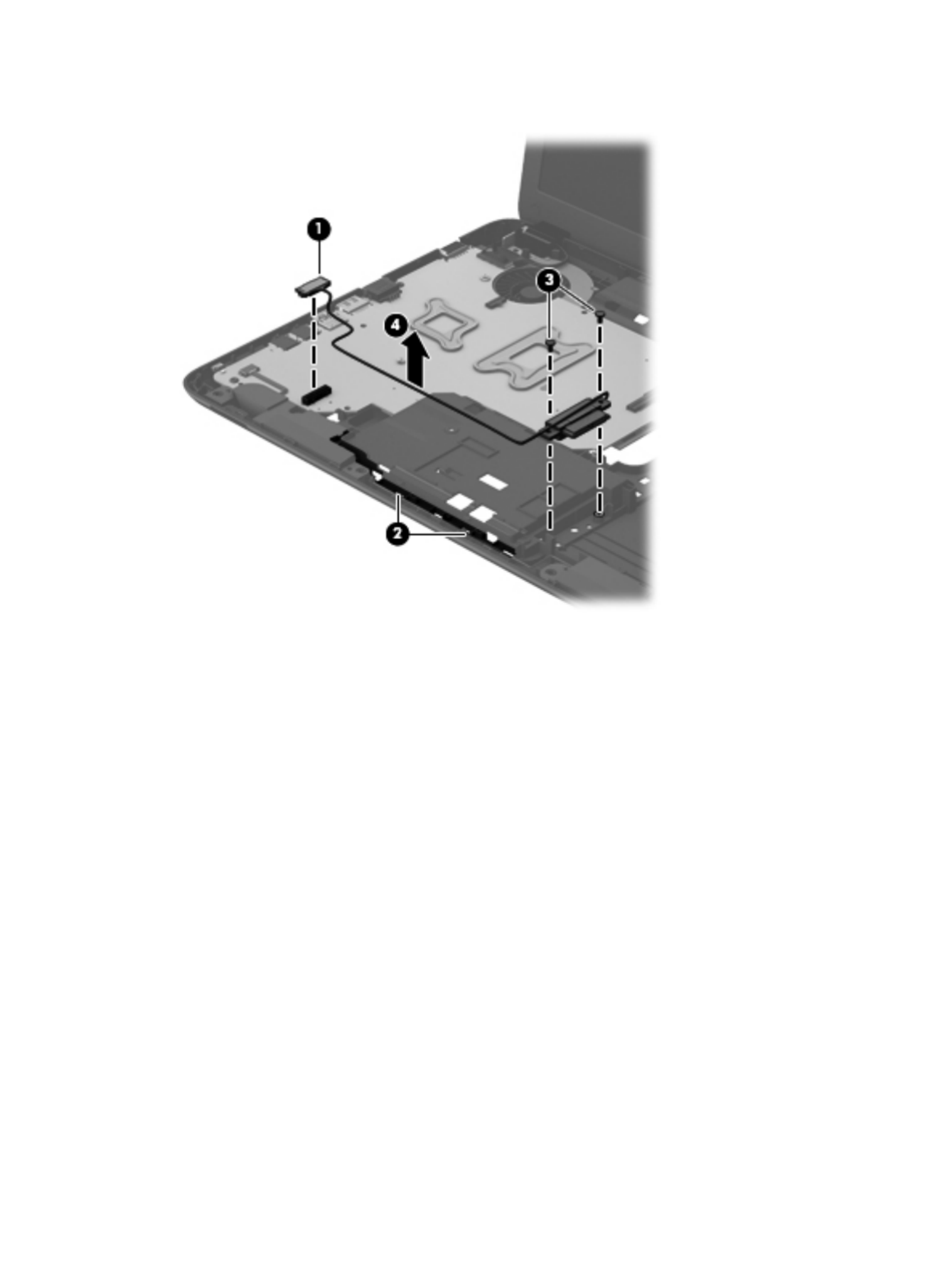
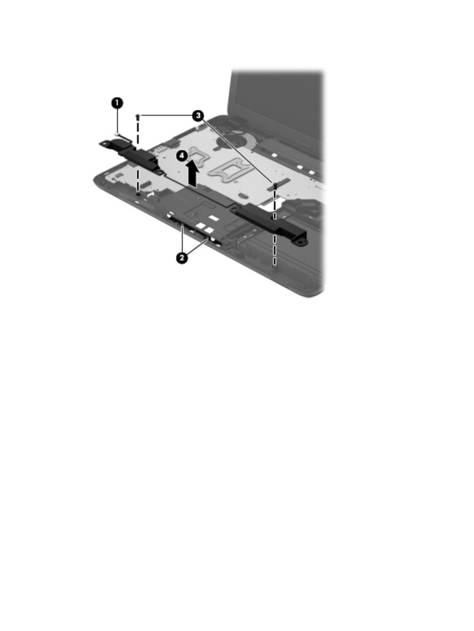
Remove the system board:
1. Disconnect the following cables from the system board.
(1) Speaker cable
(2) Optical drive connector cable
(3) Display panel cable
(4) USB board cable
(5) Power connector cable
2. Remove the three Phillips PM2.5×6.0 screws (1) that secure the system board to
the base enclosure.
3. Lift the right side of the system board (2) until it rests at an angle.
62 Chapter 4 Removal and replacement procedures

4. Remove the system board (3) by sliding it up and to the right at an angle.
Reverse this procedure to install the system board.
Fan/heat sink assembly
Description Spare part number
Fan/heat assembly (includes replacement thermal material) 688306-001
Before removing the fan/heat sink assembly, follow these steps:
1. Turn off the computer. If you are unsure whether the computer is off or in Hibernation, turn
the computer on, and then shut it down through the operating system.
2. Disconnect the power from the computer by unplugging the power cord from the computer.
3. Disconnect all external devices from the computer.
4. Remove the battery (see Battery on page 34), and then remove the following components:
a. Memory module/wireless module compartment cover (see Memory module on page 35)
b. Keyboard (see Keyboard on page 38)
c. Hard drive (see Hard drive on page 44)
Component replacement procedures 63

Reverse this procedure to install the fan/heat sink assembly.
Component replacement procedures 65

Display assembly
NOTE: The display assembly is spared at the subcomponent level only. For more display assembly
spare part information, see the individual removal subsections.
Before removing the display assembly, follow these steps:
1. Turn off the computer. If you are unsure whether the computer is off or in Hibernation, turn
the computer on, and then shut it down through the operating system.
2. Disconnect the power from the computer by unplugging the power cord from the computer.
3. Disconnect all external devices from the computer.
4. Remove the battery (see Battery on page 34).
5. Disconnect the wireless antenna cables from the WLAN module (see Memory module
on page 35).
6. Remove the following components:
a. Keyboard (see Keyboard on page 38)
b. Hard drive (see Hard drive on page 44)
c. Top cover (see Top cover on page 48)
Remove the display assembly:
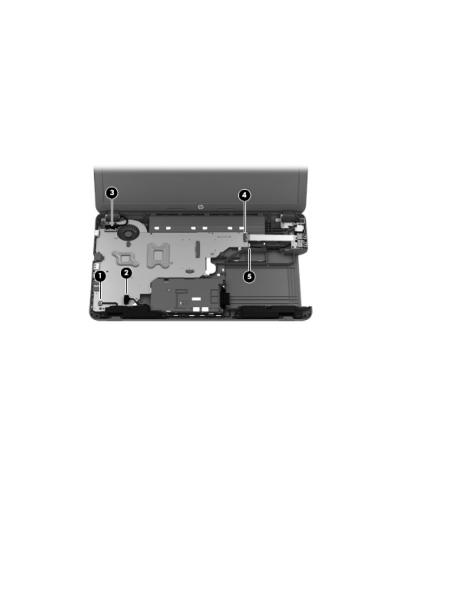
1. Disconnect the display panel cable (1) from the system board.
66 Chapter 4 Removal and replacement procedures

2. Release the wireless antenna cables (2) from the clips and routing channel built into the
base enclosure.
CAUTION: Support the display assembly when removing the following screws. Failure to
support the display assembly can result in damage to the display assembly and other
computer components.
3. Remove the five Phillips PM2.5×6.5 screws (1) that secure the display assembly to
the base enclosure.
Component replacement procedures 67

c. Remove the display bezel (6). The display bezel is available using spare part number
686255-001.
6. If it is necessary to replace the display hinge covers:
a. Remove the two Phillips PM2.5×4.0 screws (1) that secure the display hinge covers to the
display enclosure.
b. Remove the display hinge covers (2). The display hinge covers are available using spare
part number 686262-001.
Component replacement procedures 69

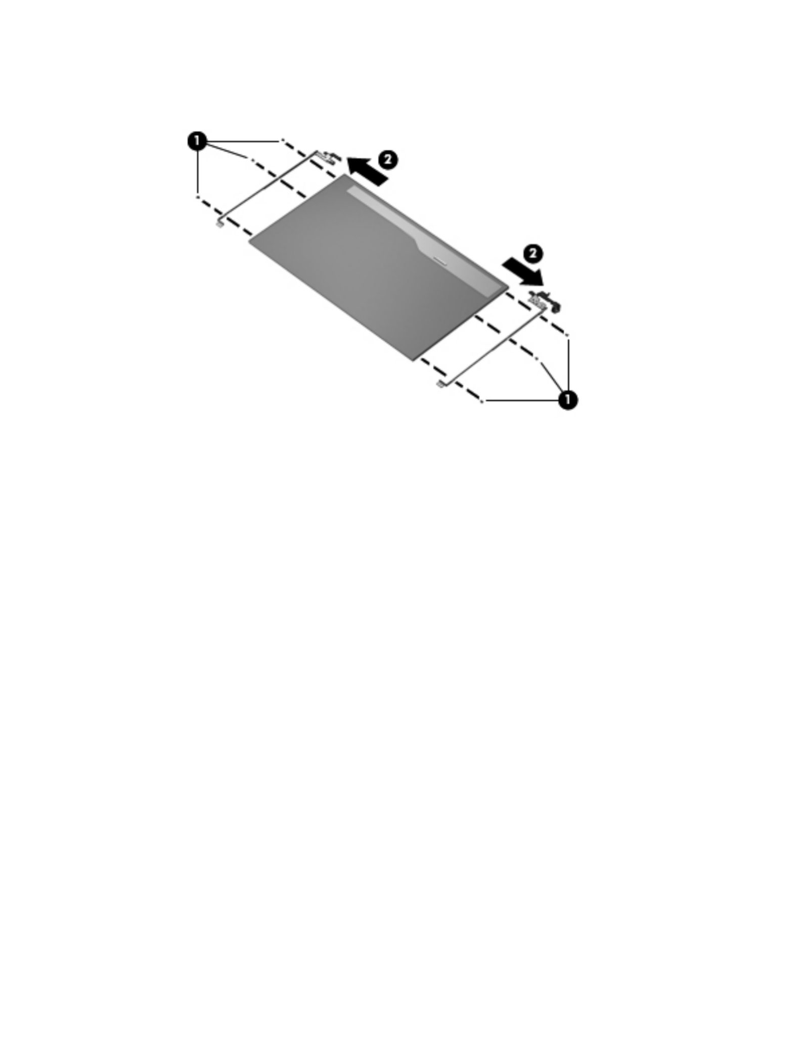
7. If it is necessary to replace the display panel:
a. Release the display panel cable (1) from the clips built into the bottom edge of the
display enclosure.
b. Remove the four Phillips PM2.5×4.0 screws (2) that secure the display panel to the
display enclosure.
c. Lift the top edge of the display panel (3), and then swing it up and forward until it rests
upside down in front of the display enclosure.
d. Release the adhesive support strip (1) that secures the display panel cable to the
display panel.
e. Detach the display panel cable (2) from the display panel. (The display panel cable is
attached to the display panel with double-sided tape.)
70 Chapter 4 Removal and replacement procedures

f. Disconnect the display panel cable (3) from the display panel.
g. Remove the display panel. The display panel is available using spare part number
686273-001.
8. If it is necessary to replace the display hinges:
a. Remove the six Phillips PM2.0×3.5 screws (1) that secure the display hinges to
the display panel.
Component replacement procedures 71
b. Remove the display hinges (2). The display hinges are available using spare part number
686262-001.
9. If it is necessary to replace the display panel cable:
a. Detach the display panel cable (1) from the display enclosure. (The display panel cable is
attached to the display enclosure with double-sided tape in multiple locations.)
b. Disconnect the webcam/microphone cable (2) from the webcam/microphone module.
72 Chapter 4 Removal and replacement procedures

10. If it is necessary to replace the webcam/microphone module, gently detach the webcam/
microphone module from the display enclosure. (The webcam/microphone module is attached to
the display enclosure with double-sided tape.) The webcam/microphone module is available using
spare part number 686285-001.
CAUTION: Due to the thin profile of the webcam/microphone module, it is easily damaged.
Take extra precaution to ensure the webcam/microphone module is not damaged when removing
and replacing the module.
NOTE: Depending on computer model, some computer models may be equipped one or two
sets of wireless antenna cables and transceivers.
11. If it is necessary to replace the wireless antenna cables and transceivers:
a. Detach the wireless antenna transceivers (1) from the display enclosure. (The wireless
antenna transceivers are attached to the display enclosure with double-sided tape.)
b. Release the wireless antenna cables from the clips and routing channels along the left, right,
and bottom edges of the display enclosure (2).
74 Chapter 4 Removal and replacement procedures

c. Remove the wireless antenna cables and transceivers (3). The wireless antenna cables and
transceivers are available using spare part number 686249-001.
Reverse this procedure to install the display assembly.
Power connector cable
Description Spare part number
Power connector cable (includes bracket) 686258-001
Before removing the power connector cable, follow these steps:
1. Turn off the computer. If you are unsure whether the computer is off or in Hibernation, turn
the computer on, and then shut it down through the operating system.
2. Disconnect the power from the computer by unplugging the power cord from the computer.
3. Disconnect all external devices from the computer.
4. Remove the battery (see Battery on page 34), and then remove the following components:
a. Memory module/wireless module compartment cover (see Memory module on page 35)
b. Keyboard (see Keyboard on page 38)
c. Hard drive (see Hard drive on page 44)
d. Top cover (see Top cover on page 48)
e. Display assembly (see Display assembly on page 66)
Remove the power connector cable:
1. Disconnect the power connector cable (1) from the system board.
2. Remove the Phillips PM2.5×6.5 screw (2) that secures the power connector and bracket to
the base enclosure.
Component replacement procedures 75

3. Remove the power connector bracket (3).
4. Remove the power connector cable (4).
Reverse this procedure to install the power connector cable.
76 Chapter 4 Removal and replacement procedures

5 Using Setup Utility (BIOS) and
System Diagnostics
Setup Utility, or Basic Input/Output System (BIOS), controls communication between all the input and
output devices on the system (such as disk drives, display, keyboard, mouse, and printer). Setup Utility
(BIOS) includes settings for the types of devices installed, the startup sequence of the computer, and the
amount of system and extended memory.
Starting Setup Utility (BIOS)
To start Setup Utility (BIOS), follow these steps:
1. Turn on or restart the computer, and then press esc while the “Press the ESC key for Startup Menu”
message is displayed at the bottom of the screen.
2. Press f10 to enter Setup Utility (BIOS).
Information about how to navigate in Setup Utility (BIOS) is located at the bottom of the screen.
NOTE: Use extreme care when making changes in Setup Utility (BIOS). Errors can prevent the
computer from operating properly.
Updating the BIOS
Updated versions of the BIOS may be available on the HP website.
Most BIOS updates on the HP website are packaged in compressed files called SoftPaqs.
Some download packages contain a file named Readme.txt, which contains information regarding
installing and troubleshooting the file.
Starting Setup Utility (BIOS) 77

Determining the BIOS version
To determine whether available BIOS updates contain later BIOS versions than those currently installed
on the computer, you need to know the version of the system BIOS currently installed.
BIOS version information (also known as ROM date and System BIOS) can be displayed by pressing fn
+esc (if you are already in Windows) or by using Setup Utility (BIOS).
1. Start Setup Utility (BIOS).
2. Use the arrow keys to select Main.
3. To exit Setup Utility (BIOS) without saving your changes, use the tab key and the arrow keys to
select Exit > Exit Discarding Changes, and then press enter.
Downloading a BIOS update
CAUTION: To reduce the risk of damage to the computer or an unsuccessful installation, download
and install a BIOS update only when the computer is connected to reliable external power using the AC
adapter. Do not download or install a BIOS update while the computer is running on battery power,
docked in an optional docking de onal power source. During thevice, or connected to an opti
download and installation, follow these instructions:
Do not disconnect power from the computer by unplugging the power cord from the AC outlet.
Do not shut down the computer or initiate Sleep or Hibernation.
Do not insert, remove, connect, or disconnect any device, cable, or cord.
1. Select Start > Help and Support > Maintain.
2. Follow the on-screen instructions to identify your computer and access the BIOS update you want
to download.
3. At the download area, follow these steps:
a. Identify the BIOS update that is later than the BIOS version currently installed on your
computer. Make a note of the date, name, or other identifier. You may need this information
to locate the update later, after it has been downloaded to your hard drive.
b. Follow the on-screen instructions to download your selection to the hard drive. Make a note
of the path to the location on your hard drive where the BIOS update is downloaded. You
will need to access this path when you are ready to install the update.
NOTE: If you connect your computer to a network, consult the network administrator before installing
any software updates, especially system BIOS updates.
BIOS installation procedures vary. Follow any instructions that are displayed on the screen after the
download is complete. If no instructions are displayed, follow these steps:
1. Open Windows Explorer by selecting Start > Computer.
2. Double-click your hard drive designation. The hard drive designation is typically Local Disk (C:).
78 Chapter 5 Using Setup Utility (BIOS) and System Diagnostics

3. Using the hard drive path you recorded earlier, open the folder on your hard drive that contains
the update.
4. Double-click the file that has an .exe extension (for example, filename.exe). The BIOS
installation begins.
5. Complete the installation by following the on-screen instructions.
NOTE: After a message on the screen reports a successful installation, you can delete the
downloaded file from your hard drive.
Using System Diagnostics
System Diagnostics allows you to run diagnostic tests to determine if the computer hardware is
functioning properly.
To start System Diagnostics:
1. Turn on or restart the computer. While the “Press the ESC key for Startup Menu” message is
displayed in the lower-left corner of the screen, press esc. When the Startup Menu is displayed,
press f2.
2. Click the diagnostic test you want to run, and then follow the on-screen instructions.
NOTE: If you need to stop a diagnostics test while it is running, press esc.
Using System Diagnostics 79
Produktspezifikationen
| Marke: | HP |
| Kategorie: | Laptop |
| Modell: | CQ58-104SR |
| Bildschirmauflösung: | 1366 x 768 Pixel |
| Touchscreen: | Nein |
| Bildschirmdiagonale: | 15.6 Zoll |
| Eingebautes Mikrofon: | Ja |
| Installiertes Betriebssystem: | Windows 7 Starter |
| Prozessorhersteller: | AMD |
| Anzahl Prozessorkerne: | 2 |
| WLAN: | Ja |
| WLAN-Standards: | 802.11b,802.11g,Wi-Fi 4 (802.11n) |
| Bluetooth: | Ja |
| Akku-/Batteriebetriebsdauer: | - h |
| Breite: | 376 mm |
| Tiefe: | 247 mm |
| Gewicht: | 2450 g |
| AC-Netzadapter: | Ja |
| Mitgelieferte Kabel: | AC |
| Produkttyp: | Notebook |
| Produktfarbe: | Schwarz |
| Akku-/Batterietechnologie: | Lithium-Ion (Li-Ion) |
| Höhe: | 31.3 mm |
| Anzahl eingebauter Lautsprecher: | 2 |
| Kopfhörerausgänge: | 1 |
| Anzahl USB 2.0 Anschlüsse: | 3 |
| Betriebstemperatur: | 5 - 35 °C |
| Relative Luftfeuchtigkeit in Betrieb: | 10 - 90 % |
| Netzstandard: | IEEE 802.11b,IEEE 802.11g,IEEE 802.11n |
| Eingebauter Ethernet-Anschluss: | Ja |
| Anzahl Ethernet-LAN-Anschlüsse (RJ-45): | 1 |
| Ursprungsland: | China |
| Betriebsanleitung: | Ja |
| Natives Seitenverhältnis: | 16:9 |
| Anzahl HDMI-Anschlüsse: | 1 |
| Ethernet LAN Datentransferraten: | 10,100 Mbit/s |
| Temperaturbereich bei Lagerung: | -20 - 60 °C |
| Luftfeuchtigkeit bei Lagerung: | 5 - 95 % |
| DVI Anschluss: | Nein |
| Mikrofon-Eingang: | Ja |
| Kabelsperre-Slot: | Nein |
| Formfaktor: | Klappgehäuse |
| Prozessor-Taktfrequenz: | 1.3 GHz |
| Prozessorfamilie: | AMD E |
| Prozessor: | E-300 |
| Kompatible Speicherkarten: | MMC,SD |
| RAM-Speicher: | 2 GB |
| Prozessor-Cache: | 1 MB |
| Prozessor Cache Typ: | L2 |
| Prozessor-Threads: | 2 |
| Interner Speichertyp: | DDR3-SDRAM |
| Integrierter Kartenleser: | Ja |
| Anzahl VGA (D-Sub) Anschlüsse: | 1 |
| Motherboard Chipsatz: | AMD A68M |
| RAM-Speicher maximal: | 8 GB |
| Treiber enthalten: | Ja |
| Nachhaltigkeitszertifikate: | EPEAT Silver,ENERGY STAR |
| Verkabelungstechnologie: | 10/100Base-T(X) |
| LED-Hintergrundbeleuchtung: | Ja |
| HDD Kapazität: | 320 GB |
| HDD Geschwindigkeit: | 5400 RPM |
| HDD Größe: | 2.5 Zoll |
| Speichermedien: | HDD |
| Gesamtspeicherkapazität: | 320 GB |
| SmartCard-Slot: | Nein |
| Höhe bei Betrieb: | -15 - 3048 m |
| Intel® Small-Business-Advantage (Intel® SBA): | Nein |
| On-Board Grafikadaptermodell: | AMD Radeon HD 6310 |
| Eingebaute Grafikadapter: | Ja |
| Dediziertes Grafikadaptermodell: | Nicht verfügbar |
| Separater Grafikadapter: | Nein |
| On-Board-Grafikadapterfamilie: | AMD Radeon HD 6000 |
| Speicherkartensteckplätze: | 2x SO-DIMM |
| Speicherlayout: | 1 x 2 GB |
| Anzahl der installierten HDDs: | 1 |
| Optisches Laufwerk - Typ: | DVD Super Multi DL |
| Betriebssystemsarchitektur: | 32-bit |
| S/PDIF-Ausgang: | Nein |
| HDD Schnittstelle: | SATA |
| Netzteilstärke: | 65 W |
| Docking-Connector: | Nein |
| ExpressCard-Slot: | Nein |
| CardBus PCMCIA Slot-Typ: | Nein |
| Typ Ladeanschluss: | DC-Anschluss |
| Eingabegerät: | Touchpad |
| Numerisches Keypad: | Nein |
| Anzahl Batteriezellen: | 6 |
| Memory Formfaktor: | SO-DIMM |
| Lautsprecher Hersteller: | Altec Lansing |
| Windows Tasten: | Ja |
| Full-size Tastatur: | Ja |
| Display-Oberfläche: | Glanz |
| Höhe bei Lagerung: | -15 - 12192 m |
| RAM-Speicher maximal (64-bit): | 8 GB |
| Display-Auflösung: | 1366 x 768 Pixel |
Brauchst du Hilfe?
Wenn Sie Hilfe mit HP CQ58-104SR benötigen, stellen Sie unten eine Frage und andere Benutzer werden Ihnen antworten
Bedienungsanleitung Laptop HP

4 Oktober 2024
3 Oktober 2024
3 Oktober 2024
3 Oktober 2024
2 Oktober 2024
2 Oktober 2024
1 Oktober 2024
30 September 2024
30 September 2024
29 September 2024
Bedienungsanleitung Laptop
- Laptop Samsung
- Laptop Acer
- Laptop Apple
- Laptop Asus
- Laptop Gigabyte
- Laptop Lexibook
- Laptop Medion
- Laptop Microsoft
- Laptop SilverCrest
- Laptop Sony
- Laptop Panasonic
- Laptop LG
- Laptop Denver
- Laptop Thomson
- Laptop BEKO
- Laptop Schneider
- Laptop Pyle
- Laptop Haier
- Laptop Coby
- Laptop Mpman
- Laptop ODYS
- Laptop Jay-Tech
- Laptop PEAQ
- Laptop Xiaomi
- Laptop Hannspree
- Laptop Hyundai
- Laptop Toshiba
- Laptop GOCLEVER
- Laptop Prixton
- Laptop ViewSonic
- Laptop Dell
- Laptop Lenovo
- Laptop MSI
- Laptop Tripp Lite
- Laptop Razer
- Laptop Targa
- Laptop Zebra
- Laptop Honor
- Laptop ADATA
- Laptop NEC
- Laptop Hercules
- Laptop Fellowes
- Laptop Airis
- Laptop Fujitsu
- Laptop Huawei
- Laptop Maxdata
- Laptop Packard Bell
- Laptop Aplic
- Laptop Kogan
- Laptop Sylvania
- Laptop SPC
- Laptop Asrock
- Laptop ECS
- Laptop Hähnel
- Laptop Oregon Scientific
- Laptop Emachines
- Laptop Ematic
- Laptop Evga
- Laptop Ibm
- Laptop Micromax
- Laptop Olidata
- Laptop Vizio
- Laptop Alienware
- Laptop Siig
- Laptop Inovia
- Laptop Getac
- Laptop XPG
- Laptop Atdec
- Laptop Vulcan
- Laptop System76
- Laptop Averatec
- Laptop Hamilton Buhl
- Laptop AORUS
- Laptop CTL
- Laptop Humanscale
- Laptop Compaq
- Laptop General Dynamics Itronix
- Laptop Everex
- Laptop Dynabook
- Laptop TechBite
- Laptop Schenker
Neueste Bedienungsanleitung für -Kategorien-

1 Dezember 2024
1 Dezember 2024
1 Dezember 2024
1 Dezember 2024

30 November 2024

16 Oktober 2024
16 Oktober 2024

15 Oktober 2024

14 Oktober 2024
13 Oktober 2024