Honeywell HRXD9 Bedienungsanleitung
Honeywell
Sicherheitskamera
HRXD9
Lesen Sie kostenlos die 📖 deutsche Bedienungsanleitung für Honeywell HRXD9 (156 Seiten) in der Kategorie Sicherheitskamera. Dieser Bedienungsanleitung war für 10 Personen hilfreich und wurde von 2 Benutzern mit durchschnittlich 4.5 Sternen bewertet
Seite 1/156

Document 900.0856 – Rev B – 02/08
User Guide
HRXD9, HRXD16
9-, 16-Channel Models
Digital Video Recorder

2
Revisions
Issue Date Revisions
1.00 12/06 New document.
2.00 10/07 Manual updated for the latest software release.
3.00 11/07 Minor changes and corrections.
A 01/08 Add DVD-RW to the manual (specifications and other places).
B 02/08 Added a Caution to the "Connecting the Power Cord" section of the
Installation chapter.
Document 900.0856 Rev B 3
02/08
FCC Compliance Statement
INFORMATION TO THE USER: This equipment has been tested and found to comply
with the limits for a Class A digital device, pursuant to part 15 of the FCC rules. These
limits are designed to provide reasonable protection against harmful interference when
the equipment is operated in a commercial environment. This equipment generates,
uses, and can radiate radio frequency energy and, if not installed and used in
accordance with the instruction manual, may cause harmful interference to radio
communications. Operation of this equipment in a residential area is likely to cause
harmful interference in which case the user will be required to correct the interference
at his own expense.
CAUTION: Changes or modifications not expressly approved by the party responsible
for compliance could void the user’s authority to operate the equipment.
This Class A digital apparatus complies with Canadian ICES-003.
Cet appareil numérique de la Classe A est conforme à la norme NMB-003 du Canada.
Explanation of Graphical Symbols
This symbol alerts the user to the presence of uninsulated "dangerous
voltage" within the product's enclosure that may be of sufficient
magnitude to constitute a risk of electric shock.
This symbol alerts the user to the presence of important operating and
maintenance (servicing) instructions in the literature accompanying the
appliance.
RISK OF ELECTRIC SHOCK
DO NOT OPEN
WARNING
WARNING: TO REDUCE THE RISK OF ELECTRIC SHOCK,
DO NOT REMOVE COVER (OR BACK).
NO USER-SERVICEABLE PARTS INSIDE.
REFER SERVICING TO QUALIFIED SERVICE PERSONNEL.

4
Compliance
WEEE (Waste Electrical and Electronic Equipment)
Correct Disposal of this Product (Applicable in the European Union and other
European countries with separate collection systems)
RoHS
This marking shown on the product or its literature, indicates that it
should not be disposed with other household wastes at the end of
its working life. To prevent possible harm to the environment or
human health from uncontrolled waste disposal, please separate
this from other types of wastes and recycle it responsibly to
promote the sustainable reuse of material resources.
Household users should contact either the retailer where they
purchased this product, or their local government office, for details
of where and how they can take this item for environmentally safe
recycling.
Business users should contact their supplier and check the terms
and conditions of the purchase contract. This product should not be
mixed with other commercial wastes for disposal.

Contents
Document 900.0856 Rev B 5
02/08
Contents
FCC Compliance Statement . . . . . . . . . . . . . . . . . . . . . . . . . . . . . . . . . . 3
Explanation of Graphical Symbols . . . . . . . . . . . . . . . . . . . . . . . . . . . . . . . 3
Compliance . . . . . . . . . . . . . . . . . . . . . . . . . . . . . . . . . . . . . . . . . . . 4
About This Document . . . . . . . . . . . . . . . . . . . . . . . . . . . . . . . . . . . . . . 13
Overview of Contents . . . . . . . . . . . . . . . . . . . . . . . . . . . . . . . . . . . . . . 13
Important Safeguards . . . . . . . . . . . . . . . . . . . . . . . . . . . . . . . . . . . . . . 14
1 Introduction . . . . . . . . . . . . . . . . . . . . . . . . . . . . . . . . . . . . . . . . . 17
Features . . . . . . . . . . . . . . . . . . . . . . . . . . . . . . . . . . . . . . . . . . . . . 17
Technical Overview . . . . . . . . . . . . . . . . . . . . . . . . . . . . . . . . . . . . . . . 18
2 Installation . . . . . . . . . . . . . . . . . . . . . . . . . . . . . . . . . . . . . . . . . . 21
Package Contents. . . . . . . . . . . . . . . . . . . . . . . . . . . . . . . . . . . . . . . . 21
Required Installation Tools . . . . . . . . . . . . . . . . . . . . . . . . . . . . . . . . . . . 21
Connecting the Video Input . . . . . . . . . . . . . . . . . . . . . . . . . . . . . . . . . . . 22
Connecting the Loop-Through Video . . . . . . . . . . . . . . . . . . . . . . . . . . . . . . 22
Connecting the Monitor . . . . . . . . . . . . . . . . . . . . . . . . . . . . . . . . . . . . . 23
Connecting a VGA Monitor . . . . . . . . . . . . . . . . . . . . . . . . . . . . . . . . . . . 24
Connecting Audio . . . . . . . . . . . . . . . . . . . . . . . . . . . . . . . . . . . . . . . . 24
Connecting Alarms . . . . . . . . . . . . . . . . . . . . . . . . . . . . . . . . . . . . . . . 25
AI 1 to 16 (Alarm-In) . . . . . . . . . . . . . . . . . . . . . . . . . . . . . . . . . . 25
GND (Ground) . . . . . . . . . . . . . . . . . . . . . . . . . . . . . . . . . . . . . 26
AO 1 to 16 (Alarm-Out) . . . . . . . . . . . . . . . . . . . . . . . . . . . . . . . . 26
ARI (Alarm Reset In) . . . . . . . . . . . . . . . . . . . . . . . . . . . . . . . . . . 26
Connecting to the RS485 Port . . . . . . . . . . . . . . . . . . . . . . . . . . . . . . . . . 27
Connecting to the USB Ports . . . . . . . . . . . . . . . . . . . . . . . . . . . . . . . . . . 27
Connecting to the RS232 Port . . . . . . . . . . . . . . . . . . . . . . . . . . . . . . . . . 28
Connecting to the Ultra Wide SCSI Port . . . . . . . . . . . . . . . . . . . . . . . . . . . . 28
Connecting to the Network Port . . . . . . . . . . . . . . . . . . . . . . . . . . . . . . . . 29
Factory Reset . . . . . . . . . . . . . . . . . . . . . . . . . . . . . . . . . . . . . . . . . . 30
Connecting the Power Cord . . . . . . . . . . . . . . . . . . . . . . . . . . . . . . . . . . 31
3 Configuration . . . . . . . . . . . . . . . . . . . . . . . . . . . . . . . . . . . . . . . . 33
Front Panel Controls . . . . . . . . . . . . . . . . . . . . . . . . . . . . . . . . . . . . . . 33
Turning on the Power . . . . . . . . . . . . . . . . . . . . . . . . . . . . . . . . . . . . . . 37
Initial Unit Setup . . . . . . . . . . . . . . . . . . . . . . . . . . . . . . . . . . . . . . . . . 37
Setup Screen . . . . . . . . . . . . . . . . . . . . . . . . . . . . . . . . . . . . . . . . . . 38
System Information . . . . . . . . . . . . . . . . . . . . . . . . . . . . . . . . . . 39
Date/Time Setup. . . . . . . . . . . . . . . . . . . . . . . . . . . . . . . . . . . . 42
Storage Screen . . . . . . . . . . . . . . . . . . . . . . . . . . . . . . . . . . . . 45
User Setup Screen . . . . . . . . . . . . . . . . . . . . . . . . . . . . . . . . . . 48

Contents
6
Shutdown Screen. . . . . . . . . . . . . . . . . . . . . . . . . . . . . . . . . . . 50
Logout Screen . . . . . . . . . . . . . . . . . . . . . . . . . . . . . . . . . . . . 51
Network and Notification Setup . . . . . . . . . . . . . . . . . . . . . . . . . . . . . . . . 51
Network Screen. . . . . . . . . . . . . . . . . . . . . . . . . . . . . . . . . . . . 51
LAN Setup Screen . . . . . . . . . . . . . . . . . . . . . . . . . . . . . . . . . . 52
Modem Setup. . . . . . . . . . . . . . . . . . . . . . . . . . . . . . . . . . . . . 56
DVRNS Setup . . . . . . . . . . . . . . . . . . . . . . . . . . . . . . . . . . . . . 57
WebGuard Setup . . . . . . . . . . . . . . . . . . . . . . . . . . . . . . . . . . . 58
Notification Setup . . . . . . . . . . . . . . . . . . . . . . . . . . . . . . . . . . . 59
Configuring Devices . . . . . . . . . . . . . . . . . . . . . . . . . . . . . . . . . . . . . . 61
Camera Setup Screen . . . . . . . . . . . . . . . . . . . . . . . . . . . . . . . . 62
Audio Setup Screen . . . . . . . . . . . . . . . . . . . . . . . . . . . . . . . . . 64
Alarm-Out Screen. . . . . . . . . . . . . . . . . . . . . . . . . . . . . . . . . . . 65
Display Screen . . . . . . . . . . . . . . . . . . . . . . . . . . . . . . . . . . . . 66
Remote Control Screen. . . . . . . . . . . . . . . . . . . . . . . . . . . . . . . . 69
Recording Settings . . . . . . . . . . . . . . . . . . . . . . . . . . . . . . . . . . . . . . . 70
Record Screen . . . . . . . . . . . . . . . . . . . . . . . . . . . . . . . . . . . . 70
Schedule Screen . . . . . . . . . . . . . . . . . . . . . . . . . . . . . . . . . . . 71
Pre-Event Screen . . . . . . . . . . . . . . . . . . . . . . . . . . . . . . . . . . . 73
Archive Screen . . . . . . . . . . . . . . . . . . . . . . . . . . . . . . . . . . . . 74
Event Settings . . . . . . . . . . . . . . . . . . . . . . . . . . . . . . . . . . . . . . . . . 75
Alarm-In Screen. . . . . . . . . . . . . . . . . . . . . . . . . . . . . . . . . . . . 76
Motion Detection Screen . . . . . . . . . . . . . . . . . . . . . . . . . . . . . . . 78
Video Loss Screen . . . . . . . . . . . . . . . . . . . . . . . . . . . . . . . . . . 83
Text-In Screen. . . . . . . . . . . . . . . . . . . . . . . . . . . . . . . . . . . . . 85
System Event Screen . . . . . . . . . . . . . . . . . . . . . . . . . . . . . . . . . 89
Event Status Screen . . . . . . . . . . . . . . . . . . . . . . . . . . . . . . . . . 93
4 Operation . . . . . . . . . . . . . . . . . . . . . . . . . . . . . . . . . . . . . . . . . . 95
Turning on the Power. . . . . . . . . . . . . . . . . . . . . . . . . . . . . . . . . . . . . . 95
Live Monitoring . . . . . . . . . . . . . . . . . . . . . . . . . . . . . . . . . . . . . . . . . 96
Active Cameo Mode . . . . . . . . . . . . . . . . . . . . . . . . . . . . . . . . . 97
PIP Mode . . . . . . . . . . . . . . . . . . . . . . . . . . . . . . . . . . . . . . . 97
Zoom Mode . . . . . . . . . . . . . . . . . . . . . . . . . . . . . . . . . . . . . . 97
PTZ Mode . . . . . . . . . . . . . . . . . . . . . . . . . . . . . . . . . . . . . . . 97
Image Adjustment . . . . . . . . . . . . . . . . . . . . . . . . . . . . . . . . . .100
Event Monitoring . . . . . . . . . . . . . . . . . . . . . . . . . . . . . . . . . . . . . . . .100
Covert Camera . . . . . . . . . . . . . . . . . . . . . . . . . . . . . . . . . . . . . . . . .101
Spot Monitoring. . . . . . . . . . . . . . . . . . . . . . . . . . . . . . . . . . . . . . . . .101
Using a Mouse . . . . . . . . . . . . . . . . . . . . . . . . . . . . . . . . . . . . . . . . .103
Recording Video . . . . . . . . . . . . . . . . . . . . . . . . . . . . . . . . . . . . . . . .104
Recording Audio . . . . . . . . . . . . . . . . . . . . . . . . . . . . . . . . . . . . . . . .105
Playing Recorded Video . . . . . . . . . . . . . . . . . . . . . . . . . . . . . . . . . . . .105
RW (Rewind) Button . . . . . . . . . . . . . . . . . . . . . . . . . . . . . . . . .106
FF (Fast Forward) Button . . . . . . . . . . . . . . . . . . . . . . . . . . . . . . .106
BACKWARD Button . . . . . . . . . . . . . . . . . . . . . . . . . . . . . . . . . .106
FORWARD Button . . . . . . . . . . . . . . . . . . . . . . . . . . . . . . . . . .106
SEARCH Button. . . . . . . . . . . . . . . . . . . . . . . . . . . . . . . . . . . .107
Camera Buttons (1 to 16). . . . . . . . . . . . . . . . . . . . . . . . . . . . . . .107
DISPLAY Button. . . . . . . . . . . . . . . . . . . . . . . . . . . . . . . . . . . .107
ZOOM Button . . . . . . . . . . . . . . . . . . . . . . . . . . . . . . . . . . . . .107
Shuttle Ring . . . . . . . . . . . . . . . . . . . . . . . . . . . . . . . . . . . . . .107
Jog Dial . . . . . . . . . . . . . . . . . . . . . . . . . . . . . . . . . . . . . . . .107
Searching Video . . . . . . . . . . . . . . . . . . . . . . . . . . . . . . . . . . . . . . . .108

Contents
Document 900.0856 Rev B 7
02/08
Go to the Date/Time . . . . . . . . . . . . . . . . . . . . . . . . . . . . . . . . . 109
Calendar Search. . . . . . . . . . . . . . . . . . . . . . . . . . . . . . . . . . . 110
Event Log Search . . . . . . . . . . . . . . . . . . . . . . . . . . . . . . . . . . 111
Text-In Search . . . . . . . . . . . . . . . . . . . . . . . . . . . . . . . . . . . . 113
Motion Search . . . . . . . . . . . . . . . . . . . . . . . . . . . . . . . . . . . . 115
Clip-Copy Screen . . . . . . . . . . . . . . . . . . . . . . . . . . . . . . . . . . 117
Print Screen . . . . . . . . . . . . . . . . . . . . . . . . . . . . . . . . . . . . . 120
Appendix A USB Hard Disk Drive Preparation . . . . . . . . . . . . . . . . . . . . . . 121
Preparing the USB-IDE Hard Disk Drive in Windows 2000 . . . . . . . . . . . . . . . . . . 121
Preparing the USB-IDE Hard Disk Drive in Windows 98 . . . . . . . . . . . . . . . . . . . 122
Appendix B Text In Search Examples . . . . . . . . . . . . . . . . . . . . . . . . . . . 123
Search Example 1 . . . . . . . . . . . . . . . . . . . . . . . . . . . . . . . . . . . . . . . 123
Search Example 2 . . . . . . . . . . . . . . . . . . . . . . . . . . . . . . . . . . . . . . . 124
Appendix C Reviewing Video Clips . . . . . . . . . . . . . . . . . . . . . . . . . . . . 127
Appendix D WebGuard . . . . . . . . . . . . . . . . . . . . . . . . . . . . . . . . . . . 131
Web Monitoring Mode . . . . . . . . . . . . . . . . . . . . . . . . . . . . . . . . . . . . 133
Web Search Mode . . . . . . . . . . . . . . . . . . . . . . . . . . . . . . . . . . . . . . 135
Appendix E Time Overlap . . . . . . . . . . . . . . . . . . . . . . . . . . . . . . . . . 139
Appendix F Troubleshooting . . . . . . . . . . . . . . . . . . . . . . . . . . . . . . . 141
Appendix G Connector Pin Outs. . . . . . . . . . . . . . . . . . . . . . . . . . . . . . 143
I/O Connector Pin Outs . . . . . . . . . . . . . . . . . . . . . . . . . . . . . . . . . . . . 143
RS485 Connector Pin Outs . . . . . . . . . . . . . . . . . . . . . . . . . . . . . . . . . . 144
Appendix H Map of Screens . . . . . . . . . . . . . . . . . . . . . . . . . . . . . . . . 145
Appendix I System Log Notices . . . . . . . . . . . . . . . . . . . . . . . . . . . . . 147
Appendix J Error Code Notices . . . . . . . . . . . . . . . . . . . . . . . . . . . . . . 149
Appendix K Specifications . . . . . . . . . . . . . . . . . . . . . . . . . . . . . . . . . 151

Figures
Document 900.0856 Rev B 9
02/08
Figures
Figure 1-1 Typical DVR Installation . . . . . . . . . . . . . . . . . . . . . . . . . . . . . . . 19
Figure 2-1 16-Channel DVR Rear Panel . . . . . . . . . . . . . . . . . . . . . . . . . . . . . 22
Figure 2-2 Video Input Connectors . . . . . . . . . . . . . . . . . . . . . . . . . . . . . . . 22
Figure 2-3 Video Loop-Through Connectors . . . . . . . . . . . . . . . . . . . . . . . . . . 22
Figure 2-4 Video Out Connectors . . . . . . . . . . . . . . . . . . . . . . . . . . . . . . . . 23
Figure 2-5 VGA Connector . . . . . . . . . . . . . . . . . . . . . . . . . . . . . . . . . . . . 24
Figure 2-6 Audio In and Out Connectors . . . . . . . . . . . . . . . . . . . . . . . . . . . . 24
Figure 2-7 Alarm Input Connectors . . . . . . . . . . . . . . . . . . . . . . . . . . . . . . . 25
Figure 2-8 Alarm Output Connectors . . . . . . . . . . . . . . . . . . . . . . . . . . . . . . 26
Figure 2-9 Alarm Reset Input Connectors . . . . . . . . . . . . . . . . . . . . . . . . . . . . 26
Figure 2-10 RS485 Connector. . . . . . . . . . . . . . . . . . . . . . . . . . . . . . . . . . . 27
Figure 2-11 Front USB Connectors . . . . . . . . . . . . . . . . . . . . . . . . . . . . . . . . 27
Figure 2-12 Rear USB Connector . . . . . . . . . . . . . . . . . . . . . . . . . . . . . . . . . 27
Figure 2-13 RS232 Connector. . . . . . . . . . . . . . . . . . . . . . . . . . . . . . . . . . . 28
Figure 2-14 SCSI Connector . . . . . . . . . . . . . . . . . . . . . . . . . . . . . . . . . . . 28
Figure 2-15 Network Connector . . . . . . . . . . . . . . . . . . . . . . . . . . . . . . . . . . 29
Figure 2-16 Factory Reset Switch . . . . . . . . . . . . . . . . . . . . . . . . . . . . . . . . . 30
Figure 2-17 Power Cord Connector . . . . . . . . . . . . . . . . . . . . . . . . . . . . . . . . 31
Figure 3-1 16-Channel DVR Front Panel. . . . . . . . . . . . . . . . . . . . . . . . . . . . . 33
Figure 3-2 Infrared Remote Control . . . . . . . . . . . . . . . . . . . . . . . . . . . . . . . 34
Figure 3-3 Login Screen . . . . . . . . . . . . . . . . . . . . . . . . . . . . . . . . . . . . . 38
Figure 3-4 Setup Screen . . . . . . . . . . . . . . . . . . . . . . . . . . . . . . . . . . . . . 38
Figure 3-5 Virtual Keyboard . . . . . . . . . . . . . . . . . . . . . . . . . . . . . . . . . . . 39
Figure 3-6 Information Screen . . . . . . . . . . . . . . . . . . . . . . . . . . . . . . . . . . 39
Figure 3-7 Upgrade Screen . . . . . . . . . . . . . . . . . . . . . . . . . . . . . . . . . . . 40
Figure 3-8 Setup Import Screen . . . . . . . . . . . . . . . . . . . . . . . . . . . . . . . . . 41
Figure 3-9 Setup Export Screen . . . . . . . . . . . . . . . . . . . . . . . . . . . . . . . . . 41
Figure 3-10 System Log Screen. . . . . . . . . . . . . . . . . . . . . . . . . . . . . . . . . . 42
Figure 3-11 Date/Time Setup Screen . . . . . . . . . . . . . . . . . . . . . . . . . . . . . . . 43
Figure 3-12 Holiday Setup Screen . . . . . . . . . . . . . . . . . . . . . . . . . . . . . . . . 44
Figure 3-13 Time Sync. Screen . . . . . . . . . . . . . . . . . . . . . . . . . . . . . . . . . . 44
Figure 3-14 Storage Information Screen . . . . . . . . . . . . . . . . . . . . . . . . . . . . . 45
Figure 3-15 Device Format Screen . . . . . . . . . . . . . . . . . . . . . . . . . . . . . . . . 46

Figures
10
Figure 3-16 Device Information Screen. . . . . . . . . . . . . . . . . . . . . . . . . . . . . . 46
Figure 3-17 Storage Status Screen. . . . . . . . . . . . . . . . . . . . . . . . . . . . . . . . 47
Figure 3-18 User Setup Screen. . . . . . . . . . . . . . . . . . . . . . . . . . . . . . . . . . 48
Figure 3-19 New Group Setup Screen . . . . . . . . . . . . . . . . . . . . . . . . . . . . . . 49
Figure 3-20 New User Setup Screen . . . . . . . . . . . . . . . . . . . . . . . . . . . . . . . 50
Figure 3-21 Shutdown Screen . . . . . . . . . . . . . . . . . . . . . . . . . . . . . . . . . . 51
Figure 3-22 Logout Screen . . . . . . . . . . . . . . . . . . . . . . . . . . . . . . . . . . . . 51
Figure 3-23 Network Menu . . . . . . . . . . . . . . . . . . . . . . . . . . . . . . . . . . . . 51
Figure 3-24 Network Setup Screen. . . . . . . . . . . . . . . . . . . . . . . . . . . . . . . . 52
Figure 3-25 LAN (Manual) Setup Screen . . . . . . . . . . . . . . . . . . . . . . . . . . . . . 53
Figure 3-26 Port Numbers Setup Screen. . . . . . . . . . . . . . . . . . . . . . . . . . . . . 54
Figure 3-27 LAN (DHCP) Setup Screen . . . . . . . . . . . . . . . . . . . . . . . . . . . . . 55
Figure 3-28 LAN (ADSL) Setup Screen. . . . . . . . . . . . . . . . . . . . . . . . . . . . . . 55
Figure 3-29 Modem Setup Screen . . . . . . . . . . . . . . . . . . . . . . . . . . . . . . . . 56
Figure 3-30 DVRNS Setup Screen . . . . . . . . . . . . . . . . . . . . . . . . . . . . . . . . 57
Figure 3-31 WebGuard Setup Screen . . . . . . . . . . . . . . . . . . . . . . . . . . . . . . 59
Figure 3-32 Notification Mail Setup Screen. . . . . . . . . . . . . . . . . . . . . . . . . . . . 59
Figure 3-33 Authentication Setup Screen . . . . . . . . . . . . . . . . . . . . . . . . . . . . 60
Figure 3-34 Notification Callback Setup Screen . . . . . . . . . . . . . . . . . . . . . . . . . 61
Figure 3-35 Device Menu . . . . . . . . . . . . . . . . . . . . . . . . . . . . . . . . . . . . . 62
Figure 3-36 Camera Setup Screen . . . . . . . . . . . . . . . . . . . . . . . . . . . . . . . . 62
Figure 3-37 Camera PTZ Setup Screen . . . . . . . . . . . . . . . . . . . . . . . . . . . . . 63
Figure 3-38 PTZ Device List . . . . . . . . . . . . . . . . . . . . . . . . . . . . . . . . . . . 63
Figure 3-39 Port Setup Window . . . . . . . . . . . . . . . . . . . . . . . . . . . . . . . . . 64
Figure 3-40 Audio Setup Screen . . . . . . . . . . . . . . . . . . . . . . . . . . . . . . . . . 64
Figure 3-41 Alarm-Out Settings Screen . . . . . . . . . . . . . . . . . . . . . . . . . . . . . 65
Figure 3-42 Alarm-Out Schedule Screen . . . . . . . . . . . . . . . . . . . . . . . . . . . . . 65
Figure 3-43 Display OSD Screen . . . . . . . . . . . . . . . . . . . . . . . . . . . . . . . . . 66
Figure 3-44 OSD Margin Screen . . . . . . . . . . . . . . . . . . . . . . . . . . . . . . . . . 67
Figure 3-45 Main Monitor Screen. . . . . . . . . . . . . . . . . . . . . . . . . . . . . . . . . 68
Figure 3-46 Spot Monitor Screen. . . . . . . . . . . . . . . . . . . . . . . . . . . . . . . . . 69
Figure 3-47 Remote Control Setup Screen. . . . . . . . . . . . . . . . . . . . . . . . . . . . 69
Figure 3-48 Record Menu. . . . . . . . . . . . . . . . . . . . . . . . . . . . . . . . . . . . . 70
Figure 3-49 Record Setup Screen . . . . . . . . . . . . . . . . . . . . . . . . . . . . . . . . 70
Figure 3-50 Schedule Setup Screen . . . . . . . . . . . . . . . . . . . . . . . . . . . . . . . 72
Figure 3-51 Default Setup Screen . . . . . . . . . . . . . . . . . . . . . . . . . . . . . . . . 73
Figure 3-52 Pre-Event Setup Screen . . . . . . . . . . . . . . . . . . . . . . . . . . . . . . . 73
Figure 3-53 Archive Setup Screen . . . . . . . . . . . . . . . . . . . . . . . . . . . . . . . . 74
Figure 3-54 Event Menu . . . . . . . . . . . . . . . . . . . . . . . . . . . . . . . . . . . . . 75
Figure 3-55 Alarm-In Settings Screen . . . . . . . . . . . . . . . . . . . . . . . . . . . . . . 76
Figure 3-56 Alarm-In Actions 1 Screen . . . . . . . . . . . . . . . . . . . . . . . . . . . . . . 76
Figure 3-57 Alarm-In Notify Menu . . . . . . . . . . . . . . . . . . . . . . . . . . . . . . . . 77
Figure 3-58 Alarm-In Actions 2 Screen . . . . . . . . . . . . . . . . . . . . . . . . . . . . . . 78

Figures
12
Figure B-1 Text-In Search Option Example 1 . . . . . . . . . . . . . . . . . . . . . . . . . .124
Figure B-2 Text-In Search Option Example 2 . . . . . . . . . . . . . . . . . . . . . . . . . .125
Figure C-1 Clip Player Screen . . . . . . . . . . . . . . . . . . . . . . . . . . . . . . . . . .127
Figure D-1 WebGuard Login Screen . . . . . . . . . . . . . . . . . . . . . . . . . . . . . .132
Figure D-2 WebGuard Screen . . . . . . . . . . . . . . . . . . . . . . . . . . . . . . . . . .133
Figure D-3 WebSearch Screen . . . . . . . . . . . . . . . . . . . . . . . . . . . . . . . . .135

Document 900.0856 Rev B 13
02/08
About This Document
This document introduces the HRXD Series Digital Video Recorder (DVR) and
describes how to install, configure, and operate the DVR.
This guide covers the 9- and 16-channel HRXD Series DVRs. The DVRs are identical
except for the number of cameras and alarms that can be connected and the number
of cameras that can be displayed. For simplicity, the illustrations and descriptions in this
guide refer to the 16-camera model.
Overview of Contents
This document contains the following chapters and appendixes:
•Chapter 1, Introduction, introduces the HRXD Series DVR, lists the features and
gives a functional overview of its components.
•Chapter 2, Installation, describes how to install the DVR and connect the system
components.
•Chapter 3, Configuration, provides an overview of the front panel controls and
LCD displays and provides instructions for configuring the DVR.
•Chapter 4, Operation, covers live monitoring, recording video and audio, playing
recorded video, and searching for video.
•Appendix A, USB Hard Disk Drive Preparation, shows how to prepare the USB
hard disk drive for computers using Microsoft® Windows® 2000/98 operating
systems.
•Appendix B, Text In Search Examples, provides typical examples of text searches.
•Appendix C, Reviewing Video Clips, describes the Clip Player program and its
features.
•Appendix D, WebGuard, demonstrates using WebGuard to access a remote DVR,
monitor live video and search for recorded video using Internet Explorer.
•Appendix E, Time Overlap, instructs how to search for recorded video when you
have overlapping time segments.
•Appendix F, Troubleshooting, provides answers for common technical issues.
•Appendix G, Connector Pin Outs, describes I/O and RS485 connector pinouts.

14
•Appendix H, Map of Screens, provides a graphical illustration of the menu
screens.
•Appendix I, System Log Notices, lists all of the System Log notices.
•Appendix J, Error Code Notices, lists the system upgrade and clip copy Error
Code notices.
•Appendix K, Specifications, lists the DVR specifications.
Important Safeguards
1. Read Instructions
All the safety and operating instructions should be read before the appliance is
operated.
2. Retain Instructions
The safety and operating instructions should be retained for future reference.
3. Cleaning
Unplug this equipment from the wall outlet before cleaning it. Do not use liquid
aerosol cleaners. Use a damp soft cloth for cleaning.
4. Attachments
Never add any attachments and/or equipment without the approval of the
manufacturer as such additions may result in the risk of fire, electric shock, or
other personal injury.
5. Water and/or Moisture
Do not use this equipment near water or in contact with water.
6. Accessories
Do not place this equipment on an unstable cart, stand, or table. The equipment
may fall, causing serious injury to a child or adult, and serious damage to the
equipment. Wall or shelf mounting should follow the manufacturer’s instructions,
and should use a mounting kit approved by the manufacturer.
This equipment and cart combination should be moved with care. Quick stops,
excessive force, and uneven surfaces may cause the equipment and cart
combination to overturn.
7. Power Sources
This equipment should be operated only from the type of power source indicated
on the marking label. If you are not sure of the type of power, please consult your
equipment dealer or local power company.

16
17. Correct Batteries
WARNING! Risk of explosion if battery is replaced by an incorrect
type. Dispose of used batteries according to the
instructions.
18. Operating Temperature
An operating temperature range is specified (see Appendix K, Specifications) so
that the customer and installer may determine a suitable operating environment
for the equipment.
19. Elevated Operating Ambient Temperature
If installed in a closed or multi-unit rack assembly, the operating ambient
temperature of the rack environment may be greater than room ambient.
Therefore, consideration should be given to installing the equipment in an
environment compatible with the specified operating temperature range.
20. Reduced Air Flow
Installation of the equipment in the rack should be such that the amount of airflow
required for safe operation of the equipment is not compromised.
21. Mechanical Loading
Mounting of the equipment in the rack should be such that a hazardous condition
is not caused by uneven mechanical loading.
22. Circuit Overloading
Consideration should be given to connection of the equipment to supply circuit
and the effect that overloading of circuits might have on over-current protection
and supply wiring. Appropriate consideration of equipment nameplate ratings
should be used when addressing this concern.
23. Reliable Earthing (Grounding)
Reliable grounding of rack mounted equipment should be maintained. Particular
attention should be given to supply connections other than direct connections to
the branch circuit (for example, use of power strips).

Introduction
Document 900.0856 Rev B 17
02/08
1
Introduction
Features
Your color digital video recorder (DVR) provides recording capabilities for nine or 16
camera inputs. It provides exceptional picture quality in both live and playback modes,
and offers the following features:
• 9 or 16 composite video input connectors
• Compatible with color (NTSC or PAL) and B&W (CCIR and EIA-170) video sources
• Auto detection for NTSC and PAL
• Multiple monitor connectors: 1 BNC Video Out, 1 SVHS, 4 Spot, 1 VGA
• Multiple search engines (Date/Time, Calendar, Event)
• Records up to 240/200 images per second (NTSC/PAL)
• “Loop-Through” video connectors
• Continuous recording in Disk Overwrite mode
• Video archiving via Ultra SCSI interface
• 3 USB 2.0 ports
• Continues recording while archiving and transmitting to remote sites during
playback
• User-friendly Graphical User Interface (GUI) menu system
• Multiple recording modes (Time-lapse, Pre-event, Alarm, Motion and Panic)
• 4-Channel audio recording and 1-channel audio playback
• Text input for ATM and POS
• Alarm connections include: Input, Output and Reset Input
• Built-in alarm buzzer
• Live or recorded video access via Ethernet or modem
• Time synchronization using industry standard protocol
• Built-in CD-RW or DVD-RW drive
• Self-diagnostics with automatic notification including hard disk drive S.M.A.R.T.
protocol
• Infrared remote control

Introduction
18
Technical Overview
In addition to replacing both a time-lapse VCR and a multiplexer in a security
installation, your DVR has many features that make it much more powerful and easier
to use than even the most advanced VCR.
The DVR converts analog NTSC or PAL video to digital images and records them on a
hard disk drive. Using a hard disk drive allows you to access recorded video almost
instantaneously; there is no need to rewind tape. The technology also allows you to
view recorded video while the DVR continues recording video.
Digitally recorded video has several advantages over analog video recorded on tape.
There is no need to adjust tracking. You can freeze frames, fast forward, fast reverse,
slow forward and slow reverse without image streaking or tearing. Digital video can be
indexed by time or events, and you can instantly view video after selecting the time or
event.
Your DVR can be set up for event or time-lapse recording. You can define times to
record, and the schedule can change for different days of the week and user-defined
holidays.
The DVR can be set up to alert you when the hard disk drive is full, or it can be set to
record over the oldest video once the disk is full.
Your DVR uses a proprietary encryption scheme making it nearly impossible to alter
video.
You can view video and control your DVR remotely by connecting via modem or
Ethernet. There is a SCSI port that can be used to record or archive video to external
hard disk drives, and there are also three USB ports that can be used to upgrade the
system or copy video clips to external hard disk, CD-RW and flash drives.
Note This manual covers the 9- and 16-channel digital video
recorders. The DVRs are identical except for the number of
cameras and alarms that can be connected and the number of
cameras that can be displayed. For simplicity, the illustrations
and descriptions in this manual refer to the 16-camera model.
Introduction
Document 900.0856 Rev B 19
02/08
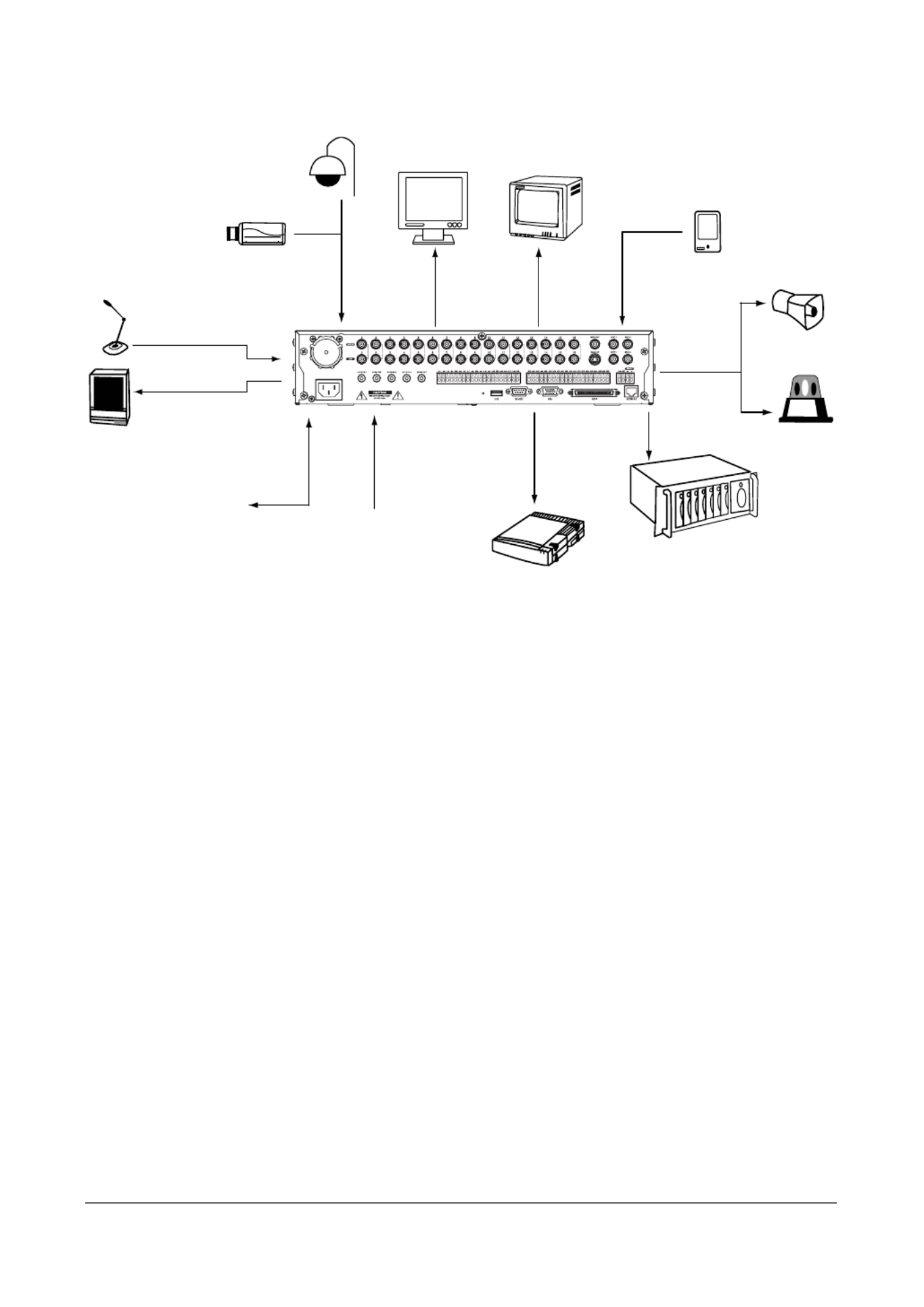
Figure 1-1 Typical DVR Installation
Audio Input x4
Audio Output
LAN or MODEM
Network Connection Internal CD-RW
or DVD-RW
9 or 16 Cameras
Digital Video
Recorder
Computer
Screen (VGA)
Video Out
Spot Monitor x4
USB Device x 3
Sensor 9 or 16
Alarm Input
External SCSI
Hard Disk Drive
Alarm
Output
9 or 16
Siren
Flashing
Light

Introduction
20

Installation
Document 900.0856 Rev B 21
02/08
2
Installation
Package Contents
The package contains the following:
• Digital Video Recorder
• Power cord
• User Guide (this document)
• Multilingual User Guide (RASplus CD-ROM)
• RASplus User Guide
• Multilingual RASplus Software CD and User Guide (RASplus CD-ROM)
• DVRNS Server Software and User Guide (RASplus CD-ROM)
• Rack-mount kit
• Assembly screws guide rails for adding Hard Disk drives
• Screws for attaching SCSI connector
• Infrared remote control
Required Installation Tools
No special tools are required to install the DVR. Refer to the installation manuals for the
other items that make up part of your system.

Installation
22
Figure 2-1 16-Channel DVR Rear Panel
Your DVR can be used with either NTSC or PAL equipment.
Note You cannot mix NTSC and PAL equipment. For example, you
cannot use a PAL camera and an NTSC monitor.
Connecting the Video Input
Figure 2-2 Video Input Connectors
Connect the coaxial cables from the video sources to the BNC Video In connectors.
Connecting the Loop-Through Video
Figure 2-3 Video Loop-Through Connectors
Ethernet PortUSB Port
Alarm Reset In
SCSI Port
Alarm Inputs
Audio In/OutPower Connector
Alarm OutsFactory Reset Switch
RS232 Port
VGA Port
Video In RS485
Spot OutSVHS Out
Video Out

Installation
24
Connecting a VGA Monitor
Figure 2-5 VGA Connector
A VGA connector is provided so that you can use a standard, multi-sync computer
monitor as your main monitor. Use the cable supplied with your monitor to connect it to
the DVR.
Note Pressing and holding DISPLAY on the front panel for 5 seconds
or longer will switch the video output between Video Out (BNC or
SVHS Out) and VGA Out. During clip copy, you cannot switch
the video output between Video Out and VGA Out.
Caution The DVR will NOT record video for about 3 seconds while
switching the video output between Video Out and VGA Out.
Connecting Audio
Note It is the user’s responsibility to determine if local laws and
regulations permit recording audio.
Figure 2-6 Audio In and Out Connectors
Installation
26
GND (Ground)
Note All the connectors marked GND are common.
Connect the ground side of the alarm input and/or alarm output to the GND connector.
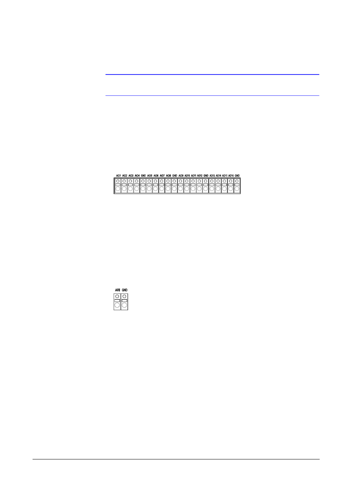
AO 1 to 16 (Alarm-Out)
Figure 2-8 Alarm Output Connectors
The DVR can activate external devices such as buzzers or lights. Connect the device to
the AO (Alarm-Out) and GND (Ground) connectors. AO is an active low open collector
output which sinks 5 mA@12V and 30 mA@5V. See Chapter 3, Configuration for
configuring alarm outputs.
ARI (Alarm Reset In)
Figure 2-9 Alarm Reset Input Connectors
An external signal to the Alarm Reset In can be used to reset both the Alarm Out signal
and the DVR’s internal buzzer. Mechanical or electrical switches can be wired to the ARI
(Alarm Reset In) and GND (Ground) connectors. The threshold voltage is below 0.3V
and should be stable at least 0.5 seconds to be detected. Connect the wires to the ARI
(Alarm Reset In) and GND (Ground) connectors.

Installation
Document 900.0856 Rev B 27
02/08
Connecting to the RS485 Port
Figure 2-10 RS485 Connector
The DVR can be controlled remotely by an external device or control system, such as a
control keyboard, using RS485 half-duplex serial communications signals. The RS485
connector can also be used to control PTZ (pan, tilt, zoom) cameras. Connect RX-/TX-
and RX+/TX+ of the control system to the - and + (respectively) of the DVR. See
Chapter 3, Configuration and the PTZ camera or remote controller manufacturer’s
manual for configuring the RS485 connection.
Connecting to the USB Ports
Figure 2-11 Front USB Connectors
Figure 2-12 Rear USB Connector
Three USB ports are provided to connect external hard disk, CD-RW or flash drives for
video clip copying or system upgrades. One USB port is located on the rear panel and
the other two are on the front panel. Position external drives close enough to the DVR
so that you can make the cable connections, usually less than 6 feet. Use the USB cable
provided with the hard disk drive to connect it to the DVR.
A USB mouse (not supplied) can be connected to one of the ports. You can use the
mouse to navigate through the screens and menus much like you would on a computer.
A PostScript™ USB printer (not supplied) can be connected to one of the ports. You can
print selected images resulting from a search. Refer to Chapter 4, Operation, Searching
Video.
A USB to Serial converter can be connected to the USB port. Multiple text-in devices
can be used with a USB to Serial converter.

Installation
28
Connecting to the RS232 Port
Figure 2-13 RS232 Connector
An RS232 port is provided to connect an external modem for remote monitoring,
configuration and software upgrades, and to connect a remote control keyboard. Use
a modem cable with a DB-9S (female) connector to connect to the DVR. See Chapter 3,
Configuration for configuring the modem.
Note The DVR is not supplied with a modem cable, and many
modems are not supplied with cables. Make certain you have the
correct cable when purchasing the modem.
Connecting to the Ultra Wide SCSI Port
Figure 2-14 SCSI Connector
A SCSI port is provided to connect external storage devices for recording or archiving
video. Connect the external SCSI hard disk drive (RAID) cable to the high-density 68-pin
female UltraWide SCSI port. The length of SCSI cable should not exceed 5 feet (1.5
meters). You can connect up to 8 UltraWide SCSI devices with SCSI IDs set from 0 to
15 except for 7, which is assigned as the Host ID.
Note The SCSI bus must be terminated, otherwise the DVR will not
operate properly.

Installation
30
Factory Reset
Figure 2-16 Factory Reset Switch
The DVR has a Factory Reset switch to the left of the USB port on the rear panel. This
switch will only be used on the rare occasions that you want to return all the settings to
the original factory settings.
Caution When using the Factory Reset, you will lose any settings you have
saved.
To reset the unit, you will need a straightened paperclip:
1. Turn the DVR off.
2. Turn it on again.
3. While the DVR is initializing, the front panel LEDs will blink. When any of the
Camera 1 to 8 LEDs blink, poke the straightened paperclip in the unlabeled hole
to the left of the USB port.
4. Hold the switch until all the LEDs on the front panel are lit.
Note When the DVR successfully resets to factory defaults, all the
LEDs on the front panel will flash five times.
5. Release the reset switch. All of the DVR’s settings are now at the original settings it
had when it left the factory.

Configuration
Document 900.0856 Rev B 33
02/08
3
Configuration
Note Your DVR should be completely installed before proceeding.
Refer to Chapter 2, Installation.
Front Panel Controls
Figure 3-1 16-Channel DVR Front Panel
The front panel looks and operates much like a VCR combined with a multiplexer. Many
of the buttons have multiple functions. The buttons on the infrared remote control, while
laid out differently, perform the same functions as those on the front panel. The
following describes each button and control. Take a few minutes to review the
descriptions. You will use these to initially set up your DVR and for daily operations.
Zoom Jog DialFFForward
Backward
RW
Arrow Buttons
EnterLEDsMenuUSB
Alarm PTZ
Internal CD-RW or DVD-RW
Freeze
Spot
Camera
Panic
Search Play/Pause
Shuttle RingSequenceDisplay
Configuration
34
Note The infrared sensor on the DVR is just to the left of the arrow
buttons. Make certain that nothing blocks the sensor, or the
remote control will not function properly.
Note You can also use a USB mouse (not supplied) to navigate
through the screens and menus much like you would on a
computer.
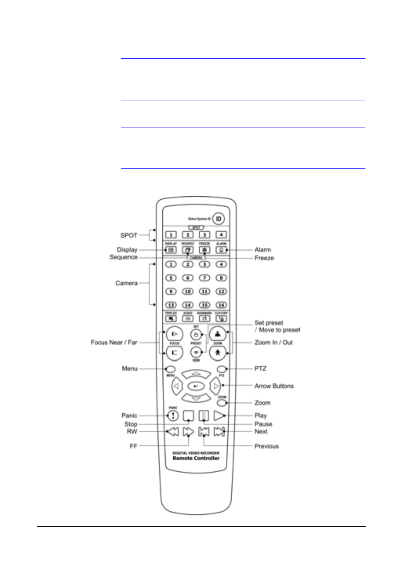
Figure 3-2 Infrared Remote Control

Configuration
Document 900.0856 Rev B 35
02/08
Note Some buttons on the infrared remote control may not be
supported, depending on the DVR model.
Table 3-1 Front Panel Buttons and Controls
Control Description
Camera Buttons
(1 to 16)
Pressing the individual camera buttons will cause the selected camera to
display full screen. Buttons 1 to 9 are also used to enter passwords.
DISPLAY Button The button has two functions. First,DISPLAY it toggles between different
display formats. The available formats are: 4x4, 3x3, 2x2 and PIP. Second,
pressing and holding the button for 5 seconds or longer will switch the video
output between Video Out (BNC or SVHS Out) and VGA Out.
SEQUENCE
Button
When in the live mode, pressing the SEQUENCE button displays live channels
sequentially.
FREEZE Button Pressing the FREEZE button freezes the current live screen.
SPOT Button Pressing the SPOT button allows you to select which cameras will display on
the four Spot monitors. After selecting the monitor you can opt to have that Spot
monitor display a single camera or all cameras sequentially. The infrared
remote control allows you to go directly to the individual Spot monitor menus.
MENU Button Pressing the MENU button enters the Setup screen. You will need to enter the
authorized user name and password to access Setup. Pressing the button also
closes the current menu or setup dialog box. In Playback mode, pressing
MENU displays the Search menu. In Search mode clip-copying can be done
instantly by pressing and holding the button for two or more seconds.
ALARM Button The ALARM button has two functions. First, it will reset the DVR’s outputs
including the internal buzzer during an alarm. Second, it will display the event
log when you are in the live monitoring mode unless there is an active alarm.
This operation can be user password protected.
ZOOM Button Pressing the ZOOM button zooms the current image on the screen. A PIP with
a rectangle temporarily displays showing what area of the screen has been
enlarged. You can use the arrow buttons to move the rectangle to another area.
Pressing (Enter) toggles the zoom size between 2x, 3x and 4x.
PTZ Button Pressing the PTZ button enters the PTZ (Pan/Tilt/Zoom) mode which allows you
to control properly configured cameras.
Up, Down, Left,
Right Arrow
Buttons
These buttons are used to navigate through menus and GUI. You can also use
them to change numbers by highlighting a number in the menu and using the
Up and Down arrow buttons to increase or decrease the number’s value.
The arrow buttons are also used to control Pan and Tilt when in the PTZ mode.
When in the PIP display format, pressing the Up and Down arrow buttons
moves the position of the small screen counter-clockwise and clockwise, and
pressing the Left and Right buttons moves through screen pages.
PANIC Button Pressing the PANIC button starts panic recording of all camera channels, and
displays on the screen. Pressing the button again will stop panic recording.

Configuration
36
HDD LED The HDD LED flickers when the DVR is recording or searching video on the hard
disk drive.
NETWORK LED The NETWORK LED flickers when the unit is connected to a network via either
Ethernet or modem.
POWER LED The POWER LED is lit when the unit is On.
Enter Button The (Enter) button selects a highlighted item or completes an entry that you
have made during system setup.
SEARCH Button Pressing the button enters the Search menu. Pressing the button SEARCH
again exits Search mode. You will need to log into the system as a qualified user
to enter Search mode from Live Monitoring mode. The button on the front panel
is also used to Zoom In while in the PTZ mode.
PLAY/PAUSE
Button
Pressing the PLAY/PAUSE button plays back images at regular speed.
Pressing the button while in Playback mode pauses the video. The screen
displays when the DVR is playing back video and displays when in the
Pause mode. The button on the front panel is also used to Zoom Out while in
the PTZ mode.
RW (Rewind)
Button
Pressing the RW button plays video backward at high speed. Pressing the
button again toggles the playback speed from , and . The
screen displays , and respectively. The button is also used for
Near Focus in the PTZ mode.
FF (Fast Forward)
Button
Pressing the FF button plays video forward at high speed. Pressing the button
again toggles the playback speed from , and . The screen
displays , and respectively. The button is also used for Far
Focus while in the PTZ mode.
FORWARD Button Pressing the FORWARD button goes to the next image. The button on the front
panel is also used to load a Preset View in the PTZ mode.
BACKWARD
Button
Pressing the BACKWARD button goes to the previous image. The button on
the front panel is also used to save Presets while in the PTZ mode.
Shuttle Ring The Shuttle Ring only functions in Playback mode. The Shuttle Ring is spring
loaded and returns to the center position when released. Turning the ring
clockwise plays video forward. Turning the ring counterclockwise plays video
backward. Playback speed varies with the amount the ring is turned. The
playback speeds are , , , x0.5, , , and .
When you release the ring, it snaps back to the center position and the video
pauses.
Table 3-1 Front Panel Buttons and Controls (cont’d)
Control Description
Configuration
Document 900.0856 Rev B 39
02/08
Press MENU to enter the setup screen.
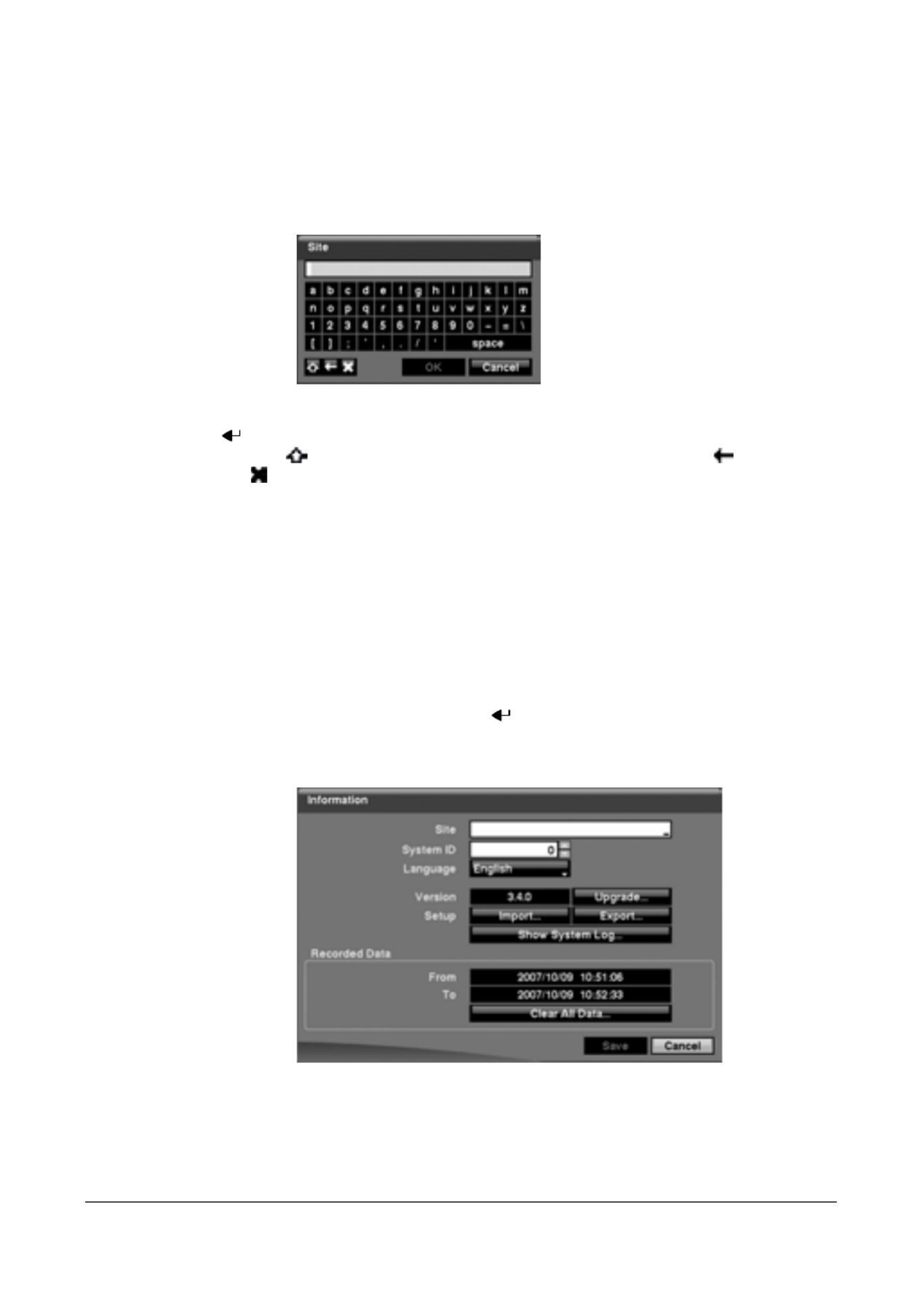
While setting up the DVR, there will be many opportunities to enter names and titles.
When making these entries, a Virtual Keyboard will appear.
Figure 3-5 Virtual Keyboard
Use the arrow keys to highlight the character you want in the name or title and press
. That character appears in the title bar and the cursor moves to the next position.
Pressing toggles between the upper and lower case keyboards, backspaces,
and deletes entered characters. You can use up to 31 characters including spaces
in your title.
Special characters can be created using ^ and a capital letter; for example, ^J for NL
(New Line), ^M for CR (Carriage Return). Special characters are commonly used by
text input devices and will be useful when performing Text-In Searches.
System Information
1. Highlight Information and press . The Information screen (Figure 3-6)
appears.
Figure 3-6 Information Screen
In the Information screen, you can: name the site location, assign a System ID
number, select the language the screens are displayed in, display the software
version number, upgrade the software, show the System Log, display recorded
time data, and clear all data.
Produktspezifikationen
| Marke: | Honeywell |
| Kategorie: | Sicherheitskamera |
| Modell: | HRXD9 |
Brauchst du Hilfe?
Wenn Sie Hilfe mit Honeywell HRXD9 benötigen, stellen Sie unten eine Frage und andere Benutzer werden Ihnen antworten
Bedienungsanleitung Sicherheitskamera Honeywell

2 Mai 2024
27 März 2024
24 März 2024
27 Februar 2024
15 Februar 2024
10 Februar 2024
29 Januar 2024
29 Januar 2024
27 Januar 2024
22 Januar 2024
Bedienungsanleitung Sicherheitskamera
- Sicherheitskamera Samsung
- Sicherheitskamera Anker
- Sicherheitskamera Approx
- Sicherheitskamera Sanyo
- Sicherheitskamera Exibel
- Sicherheitskamera Gembird
- Sicherheitskamera Hama
- Sicherheitskamera LogiLink
- Sicherheitskamera Logitech
- Sicherheitskamera Manhattan
- Sicherheitskamera Nedis
- Sicherheitskamera Sony
- Sicherheitskamera Panasonic
- Sicherheitskamera Clas Ohlson
- Sicherheitskamera Profile
- Sicherheitskamera LG
- Sicherheitskamera Bosch
- Sicherheitskamera Canon
- Sicherheitskamera TechniSat
- Sicherheitskamera Allnet
- Sicherheitskamera Eminent
- Sicherheitskamera Linksys
- Sicherheitskamera Maginon
- Sicherheitskamera Netgear
- Sicherheitskamera Schwaiger
- Sicherheitskamera Technaxx
- Sicherheitskamera Alecto
- Sicherheitskamera Denver
- Sicherheitskamera EMOS
- Sicherheitskamera Gira
- Sicherheitskamera König
- Sicherheitskamera Thomson
- Sicherheitskamera Blaupunkt
- Sicherheitskamera Braun
- Sicherheitskamera Grundig
- Sicherheitskamera Trebs
- Sicherheitskamera Pyle
- Sicherheitskamera Mitsubishi
- Sicherheitskamera Fortinet
- Sicherheitskamera Caliber
- Sicherheitskamera I-Onik
- Sicherheitskamera Jay-Tech
- Sicherheitskamera JVC
- Sicherheitskamera Motorola
- Sicherheitskamera Xiaomi
- Sicherheitskamera Abus
- Sicherheitskamera Avidsen
- Sicherheitskamera Elro
- Sicherheitskamera EZVIZ
- Sicherheitskamera Imou
- Sicherheitskamera INSTAR
- Sicherheitskamera Megasat
- Sicherheitskamera Olympia
- Sicherheitskamera Smartwares
- Sicherheitskamera Switel
- Sicherheitskamera Yale
- Sicherheitskamera Ferguson
- Sicherheitskamera Strong
- Sicherheitskamera Toshiba
- Sicherheitskamera E-Bench
- Sicherheitskamera Withings
- Sicherheitskamera Lindy
- Sicherheitskamera Waeco
- Sicherheitskamera Burg Wächter
- Sicherheitskamera Marmitek
- Sicherheitskamera Marshall
- Sicherheitskamera B/R/K
- Sicherheitskamera Marshall Electronics
- Sicherheitskamera TRENDnet
- Sicherheitskamera MINOX
- Sicherheitskamera Ricoh
- Sicherheitskamera Western Digital
- Sicherheitskamera RADEMACHER
- Sicherheitskamera First Alert
- Sicherheitskamera AVerMedia
- Sicherheitskamera Zebra
- Sicherheitskamera TP-Link
- Sicherheitskamera Humax
- Sicherheitskamera Flamingo
- Sicherheitskamera Kerbl
- Sicherheitskamera Vtech
- Sicherheitskamera Kodak
- Sicherheitskamera Broan
- Sicherheitskamera IGet
- Sicherheitskamera Adj
- Sicherheitskamera Netatmo
- Sicherheitskamera Xavax
- Sicherheitskamera InFocus
- Sicherheitskamera Overmax
- Sicherheitskamera Monacor
- Sicherheitskamera JUNG
- Sicherheitskamera Ednet
- Sicherheitskamera AG Neovo
- Sicherheitskamera Nest
- Sicherheitskamera Edimax
- Sicherheitskamera Aritech
- Sicherheitskamera Uniden
- Sicherheitskamera M-e
- Sicherheitskamera Siedle
- Sicherheitskamera Elmo
- Sicherheitskamera Conceptronic
- Sicherheitskamera D-Link
- Sicherheitskamera Eufy
- Sicherheitskamera Stabo
- Sicherheitskamera Friedland
- Sicherheitskamera EVOLVEO
- Sicherheitskamera ION
- Sicherheitskamera SPC
- Sicherheitskamera Ring
- Sicherheitskamera Digitus
- Sicherheitskamera SereneLife
- Sicherheitskamera Swann
- Sicherheitskamera Vitek
- Sicherheitskamera DataVideo
- Sicherheitskamera LevelOne
- Sicherheitskamera APC
- Sicherheitskamera Cisco
- Sicherheitskamera Grandstream
- Sicherheitskamera EVE
- Sicherheitskamera EasyMaxx
- Sicherheitskamera Tenda
- Sicherheitskamera Boss
- Sicherheitskamera Swisstone
- Sicherheitskamera Foscam
- Sicherheitskamera Ubiquiti Networks
- Sicherheitskamera Extech
- Sicherheitskamera Kramer
- Sicherheitskamera Intellinet
- Sicherheitskamera Reolink
- Sicherheitskamera Hikvision
- Sicherheitskamera FLIR
- Sicherheitskamera Arlo
- Sicherheitskamera Nexxt
- Sicherheitskamera Planet
- Sicherheitskamera EnGenius
- Sicherheitskamera Lorex
- Sicherheitskamera Google
- Sicherheitskamera Comtrend
- Sicherheitskamera Somfy
- Sicherheitskamera Aldi
- Sicherheitskamera Dedicated Micros
- Sicherheitskamera EverFocus
- Sicherheitskamera Ganz
- Sicherheitskamera GeoVision
- Sicherheitskamera Indexa
- Sicherheitskamera Raymarine
- Sicherheitskamera Revo
- Sicherheitskamera SecurityMan
- Sicherheitskamera Sitecom
- Sicherheitskamera Steren
- Sicherheitskamera Vivotek
- Sicherheitskamera Wanscam
- Sicherheitskamera Y-cam
- Sicherheitskamera ACTi
- Sicherheitskamera Epcom
- Sicherheitskamera ZKTeco
- Sicherheitskamera Moxa
- Sicherheitskamera Sonoff
- Sicherheitskamera AirLive
- Sicherheitskamera Mobotix
- Sicherheitskamera Hollyland
- Sicherheitskamera Avanti
- Sicherheitskamera Dahua Technology
- Sicherheitskamera Speco Technologies
- Sicherheitskamera Aluratek
- Sicherheitskamera 3xLOGIC
- Sicherheitskamera Inovonics
- Sicherheitskamera Atlantis Land
- Sicherheitskamera Pentatech
- Sicherheitskamera Surveon
- Sicherheitskamera Avigilon
- Sicherheitskamera Hanwha
- Sicherheitskamera Lupus Electronics
- Sicherheitskamera Joblotron
- Sicherheitskamera Lanberg
- Sicherheitskamera Verint
- Sicherheitskamera Axis
- Sicherheitskamera EtiamPro
- Sicherheitskamera Advantech
- Sicherheitskamera Wisenet
- Sicherheitskamera Chacon
- Sicherheitskamera Alula
- Sicherheitskamera KT&C
- Sicherheitskamera EKO
- Sicherheitskamera IOIO
- Sicherheitskamera KJB Security Products
- Sicherheitskamera BZBGear
- Sicherheitskamera Ansel
- Sicherheitskamera Crestron
- Sicherheitskamera Aigis
- Sicherheitskamera Pelco
- Sicherheitskamera ORNO
- Sicherheitskamera Atlona
- Sicherheitskamera Linear PRO Access
- Sicherheitskamera Laxihub
- Sicherheitskamera Aqara
- Sicherheitskamera Tecno
- Sicherheitskamera Lutec
- Sicherheitskamera Brinno
- Sicherheitskamera Night Owl
- Sicherheitskamera Exacq
- Sicherheitskamera UniView
- Sicherheitskamera Alfatron
- Sicherheitskamera BLOW
- Sicherheitskamera Digimerge
- Sicherheitskamera Milestone Systems
- Sicherheitskamera Inkovideo
- Sicherheitskamera Ecobee
- Sicherheitskamera Infortrend
- Sicherheitskamera Promise Technology
- Sicherheitskamera VideoComm
- Sicherheitskamera Feelworld
- Sicherheitskamera Kwikset
- Sicherheitskamera Kguard
- Sicherheitskamera HiLook
- Sicherheitskamera Mach Power
- Sicherheitskamera Digital Watchdog
- Sicherheitskamera Ernitec
- Sicherheitskamera Channel Vision
- Sicherheitskamera Ikegami
- Sicherheitskamera Gewiss
- Sicherheitskamera Arenti
- Sicherheitskamera Qoltec
- Sicherheitskamera Weldex
- Sicherheitskamera Costar
- Sicherheitskamera American Dynamics
- Sicherheitskamera Sentry360
- Sicherheitskamera Seco-Larm
- Sicherheitskamera ALC
- Sicherheitskamera Spyclops
- Sicherheitskamera Hawking Technologies
- Sicherheitskamera IDIS
- Sicherheitskamera EFB Elektronik
- Sicherheitskamera I3International
- Sicherheitskamera B & S Technology
- Sicherheitskamera Astak
- Sicherheitskamera Qian
- Sicherheitskamera Qolsys
- Sicherheitskamera Wasserstein
- Sicherheitskamera Turing
- Sicherheitskamera Epiphan
Neueste Bedienungsanleitung für -Kategorien-

4 Dezember 2024
4 Dezember 2024
4 Dezember 2024
4 Dezember 2024
4 Dezember 2024
3 Dezember 2024
3 Dezember 2024

2 Dezember 2024
25 November 2024
24 November 2024