Hikvision DS-2CE16C8T-IW3Z Bedienungsanleitung
Hikvision
Überwachungskamera
DS-2CE16C8T-IW3Z
Lesen Sie kostenlos die 📖 deutsche Bedienungsanleitung für Hikvision DS-2CE16C8T-IW3Z (4 Seiten) in der Kategorie Überwachungskamera. Dieser Bedienungsanleitung war für 24 Personen hilfreich und wurde von 2 Benutzern mit durchschnittlich 4.5 Sternen bewertet
Seite 1/4
TURBO HD
HLC HD Bullet Camera
User Manual
Regulatory Information
FCC Information
FCC compliance: This equipment has been
tested and found to comply with the limits for a
digital device, pursuant to part 15 of the FCC
Rules. These limits are designed to provide
reasonable protection against harmful
interference when the equipment is operated in
a commercial environment. This equipment
generates, uses, and can radiate radio
frequency energy and, if not installed and used
in accordance with the instruction manual, may
cause harmful interference to radio
communications. Operation of this equipment in
a residential area is likely to cause harmful
interference in which case the user will be
required to correct the interference at his own
expense.
FCC Conditions
This device complies with part 15 of the FCC
Rules. Operation is subject to the following two
conditions:
1. This device may not cause harmful
interference.
2. This device must accept any interference
received, including interference that may
cause undesired operation.
EU Conformity Statement
upon the purchase of equivalent new equipment,
or dispose of it at designated collection points.
For more information see: www.recyclethis.info.
2006/66/EC (battery directive):This
product contains a battery that cannot
be disposed of as unsorted municipal
waste in the European Union.
See the product documentation for specific
battery information. The battery is marked with
this symbol, which may include lettering to
indicate cadmium (Cd), lead (Pb), or mercury (Hg).
For proper recycling, return the battery to your
supplier or to a designated collection point. For
more information see: www.recyclethis.info.
U D.6L0201D2020A01
2012/19/EU (WEEE directive):
Products marked with this symbol
cannot be disposed of as unsorted
municipal waste in the European
Union. For proper recycling, return
this product to your local supplier
This product and - if applicable - the
supplied accessories too are marked
with "C E" and comply therefore with
the applicable harmonized European
standards listed under the Low Voltage Directive
2006/95/EC, the EMC Directive 2004/108/EC,
the RoHS Directive 2011/65/EU.
This series of camera adopts new generation
sensor with high sensitivity and advanced circuit
design technology It features high resolution,.
low image distortion and low noise, etc , which.
makes it suitable for surveillance system and
image processing system.
lHigh performance 1.37MP CMOS sensor and
high resolution bring high-quality image
OSD menu, parameters are configurable
l
lWhite Light Compensation
l 3D NR
lAuto white balance, auto gain control
lIP 66
1 Introduction
1.1 Product Features
1.2 Overview
Thank you for purchasing our product. If there
are any questions, or requests, please do not
hesitate to contact the dealer.
This manual applies to DS-2CE16C8T-IW3Z
model HLC HD bullet camera.
This manual may contain several technical
incorrect places or printing errors, and the
content is subject to change without notice.
The updates will be added to the new version of
this manual. We will readily improve or update
the products or procedures described in the
manual.
0200001050728
Please refer to the product specification for
camera parameters and functions.
Privacy Notice
Surveillance laws vary by jurisdiction. Check
all relevant laws in your jurisdiction before using
this product for surveillance purposes to ensure
that your use of this product conforms.
Industry Canada ICES-003 Compliance
.
This device meets the CAN ICES-3 (A)/NMB-3(A)
standards requirements.
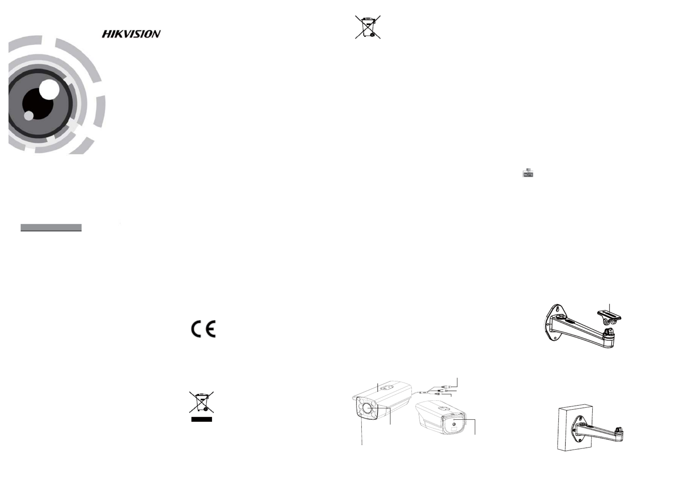
1.2.1 Overview of HLC Bullet Camera
Figure 1-1 Overview of Bullet Camera
Make sure that the wall is strong enough to
withstand at least 4 times the weight of the
camera and the bracket.
2 Installation
Before you start:
l Please make sure that the device in the package
is in good condition and all the assembly parts
are included.
l Make sure that all the related equipment is
power-off during the installation.
l Check the specification of the products for the
installation environment.
l Check whether the power supply is matched
with your power output to avoid damage.
l If the product does not function properly,
please contact your dealer or the nearest
service center. Do not disassemble the camera
for repair or maintenance by yourself.
White Light Compensation
Sun Shield
CVBS Cable
Power Cable
HD Video Cable
Photosensitive Resistor
Motorized Lens
2.1 Wall Mounting
Steps:
1.Depart the tiltable bracket module from the
bracket, as shown in Figure 2-1.
Figure 2-1 Depart the Tiltable Bracket Module
Tiltable Bracket Module
2.Fix the bracket onto the wall with M6 expansion
screws, as sown in the figure 2-2.
Figure 2-2 Fix the Bracket onto the Wall


3 Menu Operation
Figure 3-1 Main Menu
VIDEO SETTING
BRIGHTNESS
EXPOSURE MODE
AGC
SHUTTER
SATURATION
3D NR
AUTO
MANUAL
MOTION
PRIVACY
D-ZOOM
LIGHT
COMPENSATION
CONTRAST
SHARPNESS
MIRROR
You can call the menu and adjust the camera
parameters with the direction button or a coaxial
camera controller (purchase separately). You can
also call the menu with supported DVR.
3.1 VIDEO.OUT
PAL or NTSC is selectable .
3.2 LAN GUAGE
Chinese and English are selectable.
3.3.2 EXPOSURE
EXPOSURE
1. BRIGHTNESS ---|------10
2. EXPOSURE HLC
3. AGC HIGH
4. SHUTTER OFF
Figure 3-2 Exposure
Move the cursor to EX PO SUR E and confirm to enter
the exposure setting interface. You can set the value
of brightness, select the exposure mode, AGC and
enable/disable the shutter.
BRIGHT NESS: You can set the brightness value
from 1 to 10.
Global and HLC mode are selectable.EXPOSURE:
: You can set the A GC as High, Middle, and Low.AGC
: The default value is 1/100. You can setSHUTT ER
a higher shutter value as to improve the image
quality when the vehicle speed is very high.
3.3.3 White Balance (W B)
Move the cursor to White Balance and press left/
right direction key to select the white balance mode
as Manual and Auto.
Select manual mode and enter the white balance
setting interface. You can adjust the value of Red
and Blue.
3.3.4 VIDEO SET TIN GS
Move the cursor to Video Settings and confirm to
enter the video setting interface.
VIDEO SETTING
1. CONTRAST 5
2. SHARPNESS 8
3. SATURATION 6
4. 3D NR OFF
5. MIRROR OFF
6. RETURN 8
Figure 3-5 Special
MOTION
1. SENSITIVITY HIGH
2. AREA 0 8
3. AREA 1 8
4. AREA 2 8
5. AREA 3 8
6. RETURN 8
Figure 3-6 Motion Detection
Motion: Select a MOT IO N area. Set the sensitivity
level as high, middle. or low.
Four areas are selectable for setting the motion
detection.
Privacy: Move the cursor to Privacy and confirm to
enter the video setting interface. You can select the
privacy color as mosaic, white, yellow, green, and
other colors. Up to eight areas can be set.
3.3.8 RESE T
Reset all the settings to the default.
3.3.9 EXIT
Press to exit the menu.OK
Mirror: Central, Vertical, Horizontal, and OF F are
selectable.
Figure 2-3 Attach the Tiltable Bracket Module
4.Route the cables to the cable hole and connect
the corresponding cables.
5.Fix the camera and the tiltable bracket module
to the bracket.
3. Attach the tiltable bracket module to the camera
with the supplied 1/4-20UN C screws.
Figure 2-4 Fix the Camera to the Bracket
6. Adjust the viewing angle.
1). Loosen P-Direction adjusting screw to adjust
the pan position (0 ~ 360 ).° °
2). Loosen T-Direction adjusting screw to adjust
the tilting position(0 ~ 90 ).° °
T-Direction Adjusting Screw
P-Direction Adjusting Screw
Figure 2-5 Image Adjustment
3.3.1 FOCUS
1. Enter the focus interface and adjust the camera
towards the scene.
MANUAL
1. RED 5
2. BLUE 4
3. RETURN
Figure 3-3 White Balance
Figure 3-4 Video Settings
2. Move the cursor to F OC U S+ (-) and click to focus,
and move the cursor to Z OO M+(-) and click to
zoom in and out.
3. After adjusting the camera lens, click Iris+ to save
the settings and exit the focus interface. 3.3.5 SPECIAL
Move the cursor to Special and confirm to enter
the video setting interface. You can set the motion
detection, privacy mask, digital zoom, and light
compensation, as shown in the figure 3-5.
SPECIAL
1. Motion 8
2. Privacy Mask 8
3. D-Zoom --|------ 20
4. Light OFF
5. RETURN 8
Contrast: Adjust the contrast from 1 to 10.
: Adjust the sharpness from 1 to 10.Sharpness
: Adjust the saturation from 1 to 10.Saturation
: Select the 3D NR level from high, middle,3D N R
and low.
3.3.6 DIG ITAL ZOOM
Move the cursor to D-Zoom and s et the zoom ratio
by pressing left/right direction keys. The zoom ratio
range varies from 50 to 100.
3.3.7 LIGH T C OMPE NSATION
Move the cursor to Light Compensation and set the
light mode as ON, OFF, or AU TO.
The light compensation level can be set from 1 to 5.
3.3 SE T UP
2.2 Pendent Mounting
1. Attach the pole bracket to the pole with the
supplied M6*20_3pcs screws.
Figure 2-6 Fix the Bracket onto the Pole
2. Attach the camera to the pole with the supplied
1/4-20UNC screws.
Steps:
Figure 2-7 Attach the Bracket to the Camera
3. Adjust the viewing angle.
1). Loosen P-Direction adjusting screw to adjust
the pan position (0 ~ 360 ).° °
2). Loosen T-Direction adjusting screw to adjust
the tilting position(0 ~ 180 ).° °
Figure 2-8 Image Adjustment
Produktspezifikationen
| Marke: | Hikvision |
| Kategorie: | Überwachungskamera |
| Modell: | DS-2CE16C8T-IW3Z |
Brauchst du Hilfe?
Wenn Sie Hilfe mit Hikvision DS-2CE16C8T-IW3Z benötigen, stellen Sie unten eine Frage und andere Benutzer werden Ihnen antworten
Bedienungsanleitung Überwachungskamera Hikvision

13 Oktober 2024
13 Oktober 2024
13 Oktober 2024
11 Oktober 2024
11 Oktober 2024
11 Oktober 2024
8 Oktober 2024
3 Oktober 2024
3 Oktober 2024
2 Oktober 2024
Bedienungsanleitung Überwachungskamera
- Überwachungskamera Samsung
- Überwachungskamera Approx
- Überwachungskamera Belkin
- Überwachungskamera Sanyo
- Überwachungskamera Exibel
- Überwachungskamera Gembird
- Überwachungskamera Genius
- Überwachungskamera Hama
- Überwachungskamera LogiLink
- Überwachungskamera Logitech
- Überwachungskamera Manhattan
- Überwachungskamera Nedis
- Überwachungskamera Niceboy
- Überwachungskamera Philips
- Überwachungskamera Sony
- Überwachungskamera Trust
- Überwachungskamera Panasonic
- Überwachungskamera Clas Ohlson
- Überwachungskamera Profile
- Überwachungskamera ZyXEL
- Überwachungskamera Bosch
- Überwachungskamera Laserliner
- Überwachungskamera Buffalo
- Überwachungskamera Canon
- Überwachungskamera Velleman
- Überwachungskamera Powerfix
- Überwachungskamera Eminent
- Überwachungskamera Linksys
- Überwachungskamera Maginon
- Überwachungskamera Netgear
- Überwachungskamera Technaxx
- Überwachungskamera Alecto
- Überwachungskamera Denver
- Überwachungskamera EMOS
- Überwachungskamera Gira
- Überwachungskamera König
- Überwachungskamera MarQuant
- Überwachungskamera Renkforce
- Überwachungskamera Thomson
- Überwachungskamera Trevi
- Überwachungskamera Blaupunkt
- Überwachungskamera Schneider
- Überwachungskamera Trebs
- Überwachungskamera Pyle
- Überwachungskamera Topcom
- Überwachungskamera Pioneer
- Überwachungskamera JVC
- Überwachungskamera Motorola
- Überwachungskamera Xiaomi
- Überwachungskamera Abus
- Überwachungskamera Avidsen
- Überwachungskamera Elro
- Überwachungskamera EZVIZ
- Überwachungskamera Imou
- Überwachungskamera INSTAR
- Überwachungskamera Megasat
- Überwachungskamera Olympia
- Überwachungskamera Smartwares
- Überwachungskamera Switel
- Überwachungskamera Yale
- Überwachungskamera Ferguson
- Überwachungskamera Orion
- Überwachungskamera Gigaset
- Überwachungskamera Strong
- Überwachungskamera Toshiba
- Überwachungskamera Garmin
- Überwachungskamera Perel
- Überwachungskamera Netis
- Überwachungskamera Lindy
- Überwachungskamera Fenton
- Überwachungskamera Waeco
- Überwachungskamera Acme
- Überwachungskamera Burg Wächter
- Überwachungskamera Marmitek
- Überwachungskamera Marshall
- Überwachungskamera Honeywell
- Überwachungskamera B/R/K
- Überwachungskamera Marshall Electronics
- Überwachungskamera TRENDnet
- Überwachungskamera Targa
- Überwachungskamera First Alert
- Überwachungskamera AVerMedia
- Überwachungskamera Zebra
- Überwachungskamera TP-Link
- Überwachungskamera Flamingo
- Überwachungskamera Kodak
- Überwachungskamera Rollei
- Überwachungskamera IGet
- Überwachungskamera Adj
- Überwachungskamera Netatmo
- Überwachungskamera Duramaxx
- Überwachungskamera Ebode
- Überwachungskamera Xavax
- Überwachungskamera InFocus
- Überwachungskamera Overmax
- Überwachungskamera Monoprice
- Überwachungskamera Monacor
- Überwachungskamera JUNG
- Überwachungskamera Ednet
- Überwachungskamera AG Neovo
- Überwachungskamera Nest
- Überwachungskamera Edimax
- Überwachungskamera V-TAC
- Überwachungskamera Aritech
- Überwachungskamera Uniden
- Überwachungskamera Kogan
- Überwachungskamera Genie
- Überwachungskamera M-e
- Überwachungskamera Elmo
- Überwachungskamera Lumens
- Überwachungskamera Jablocom
- Überwachungskamera Conceptronic
- Überwachungskamera D-Link
- Überwachungskamera Eufy
- Überwachungskamera Stabo
- Überwachungskamera Friedland
- Überwachungskamera EVOLVEO
- Überwachungskamera SPC
- Überwachungskamera August
- Überwachungskamera Ring
- Überwachungskamera Digitus
- Überwachungskamera SereneLife
- Überwachungskamera Swann
- Überwachungskamera Vitek
- Überwachungskamera DataVideo
- Überwachungskamera LevelOne
- Überwachungskamera Aida
- Überwachungskamera APC
- Überwachungskamera Beafon
- Überwachungskamera Chuango
- Überwachungskamera Cisco
- Überwachungskamera Grandstream
- Überwachungskamera Delta Dore
- Überwachungskamera EVE
- Überwachungskamera Defender
- Überwachungskamera Tenda
- Überwachungskamera Swisstone
- Überwachungskamera Foscam
- Überwachungskamera Ubiquiti Networks
- Überwachungskamera Kramer
- Überwachungskamera Vaddio
- Überwachungskamera Intellinet
- Überwachungskamera Reolink
- Überwachungskamera Swan
- Überwachungskamera FLIR
- Überwachungskamera Furrion
- Überwachungskamera Arlo
- Überwachungskamera Nexxt
- Überwachungskamera Planet
- Überwachungskamera EnGenius
- Überwachungskamera Dörr
- Überwachungskamera Lorex
- Überwachungskamera Ikan
- Überwachungskamera Comtrend
- Überwachungskamera Somfy
- Überwachungskamera Dahua
- Überwachungskamera Dedicated Micros
- Überwachungskamera DIO
- Überwachungskamera EasyN
- Überwachungskamera Escam
- Überwachungskamera EverFocus
- Überwachungskamera Ganz
- Überwachungskamera GeoVision
- Überwachungskamera Hombli
- Überwachungskamera Home Protector
- Überwachungskamera Iiquu
- Überwachungskamera Indexa
- Überwachungskamera Interlogix
- Überwachungskamera KlikaanKlikuit
- Überwachungskamera Kompernass
- Überwachungskamera Mr Safe
- Überwachungskamera Naxa
- Überwachungskamera Nordval
- Überwachungskamera Notifier
- Überwachungskamera Oplink
- Überwachungskamera Provision ISR
- Überwachungskamera Quantum
- Überwachungskamera Raymarine
- Überwachungskamera Revo
- Überwachungskamera SAB
- Überwachungskamera Satel
- Überwachungskamera SecurityMan
- Überwachungskamera Sinji
- Überwachungskamera SMC
- Überwachungskamera Sonic Alert
- Überwachungskamera Sricam
- Überwachungskamera Steren
- Überwachungskamera Storage Options
- Überwachungskamera Tenvis
- Überwachungskamera Hive
- Überwachungskamera Ubiquiti
- Überwachungskamera Vivotek
- Überwachungskamera Woonveilig
- Überwachungskamera Y-cam
- Überwachungskamera ACTi
- Überwachungskamera AVer
- Überwachungskamera Epcom
- Überwachungskamera ZKTeco
- Überwachungskamera AirLive
- Überwachungskamera Mobotix
- Überwachungskamera Dahua Technology
- Überwachungskamera Speco Technologies
- Überwachungskamera 3xLOGIC
- Überwachungskamera Atlantis Land
- Überwachungskamera CRUX
- Überwachungskamera Pentatech
- Überwachungskamera Summer Infant
- Überwachungskamera Illustra
- Überwachungskamera Surveon
- Überwachungskamera Avigilon
- Überwachungskamera Brilliant
- Überwachungskamera Hanwha
- Überwachungskamera Lanberg
- Überwachungskamera Verint
- Überwachungskamera Axis
- Überwachungskamera EtiamPro
- Überwachungskamera MEE Audio
- Überwachungskamera Advantech
- Überwachungskamera Chacon
- Überwachungskamera Alula
- Überwachungskamera EKO
- Überwachungskamera IOIO
- Überwachungskamera KJB Security Products
- Überwachungskamera BZBGear
- Überwachungskamera Adesso
- Überwachungskamera Brickcom
- Überwachungskamera Insteon
- Überwachungskamera Aigis
- Überwachungskamera Pelco
- Überwachungskamera ORNO
- Überwachungskamera Atlona
- Überwachungskamera Linear PRO Access
- Überwachungskamera Laxihub
- Überwachungskamera Valueline
- Überwachungskamera Aqara
- Überwachungskamera Tecno
- Überwachungskamera Lutec
- Überwachungskamera Brinno
- Überwachungskamera Night Owl
- Überwachungskamera WyreStorm
- Überwachungskamera Exacq
- Überwachungskamera Equip
- Überwachungskamera AVMATRIX
- Überwachungskamera UniView
- Überwachungskamera Alfatron
- Überwachungskamera Syscom
- Überwachungskamera BLOW
- Überwachungskamera Videotec
- Überwachungskamera DSC
- Überwachungskamera AViPAS
- Überwachungskamera Milestone Systems
- Überwachungskamera Inkovideo
- Überwachungskamera Hamlet
- Überwachungskamera Mobi
- Überwachungskamera Infortrend
- Überwachungskamera VideoComm
- Überwachungskamera Kguard
- Überwachungskamera Boyo
- Überwachungskamera HiLook
- Überwachungskamera Mach Power
- Überwachungskamera Canyon
- Überwachungskamera Digital Watchdog
- Überwachungskamera Ernitec
- Überwachungskamera Ikegami
- Überwachungskamera Gewiss
- Überwachungskamera Weldex
- Überwachungskamera Costar
- Überwachungskamera Sentry360
- Überwachungskamera ALC
- Überwachungskamera Spyclops
- Überwachungskamera Compro
- Überwachungskamera IDIS
- Überwachungskamera I3International
- Überwachungskamera B & S Technology
- Überwachungskamera Qian
- Überwachungskamera Accsoon
- Überwachungskamera Control4
- Überwachungskamera Petcube
- Überwachungskamera Apeman
- Überwachungskamera ATN
- Überwachungskamera IC Intracom
- Überwachungskamera POSline
- Überwachungskamera Watec
- Überwachungskamera ETiger
- Überwachungskamera Videcon
- Überwachungskamera BirdDog
- Überwachungskamera Topica
- Überwachungskamera Rostra
- Überwachungskamera Caddx
- Überwachungskamera Whistler
- Überwachungskamera ClearView
- Überwachungskamera Beseye
- Überwachungskamera IMILAB
- Überwachungskamera CNB Technology
- Überwachungskamera Tapo
- Überwachungskamera Securetech
- Überwachungskamera NetMedia
- Überwachungskamera Nivian
- Überwachungskamera Guardzilla
- Überwachungskamera Blink
- Überwachungskamera Zavio
- Überwachungskamera Campark
- Überwachungskamera IPX
- Überwachungskamera Annke
- Überwachungskamera AVTech
- Überwachungskamera Vimtag
- Überwachungskamera Security Labs
- Überwachungskamera Seneca
- Überwachungskamera Vosker
- Überwachungskamera Owltron
- Überwachungskamera Enabot
- Überwachungskamera Luis Energy
- Überwachungskamera Sir Gawain
- Überwachungskamera VisorTech
- Überwachungskamera Milesight
- Überwachungskamera GVI Security
- Überwachungskamera Conbrov
- Überwachungskamera HuddleCamHD
- Überwachungskamera Setti+
- Überwachungskamera BIRDFY
- Überwachungskamera I-PRO
- Überwachungskamera DVDO
- Überwachungskamera TCP
Neueste Bedienungsanleitung für -Kategorien-

15 Oktober 2024

15 Oktober 2024
14 Oktober 2024
14 Oktober 2024
10 Oktober 2024
9 Oktober 2024
9 Oktober 2024
8 Oktober 2024
7 Oktober 2024
6 Oktober 2024