Hikvision DS-2CD6426F-50(4MM)(8M) Bedienungsanleitung
Hikvision
Überwachungskamera
DS-2CD6426F-50(4MM)(8M)
Lesen Sie kostenlos die 📖 deutsche Bedienungsanleitung für Hikvision DS-2CD6426F-50(4MM)(8M) (173 Seiten) in der Kategorie Überwachungskamera. Dieser Bedienungsanleitung war für 15 Personen hilfreich und wurde von 2 Benutzern mit durchschnittlich 4.5 Sternen bewertet
Seite 1/173

User Manual of Network Camera
0
User Manual
UD01171B
Network Camera

Network Camera User Manual
1
User Manual
COPYRIGHT ©2016 Hangzhou Hikvision Digital Technology Co., Ltd.
ALL RIGHTS RESERVED.
Any and all information, including, among others, wordings, pictures, graphs are the
properties of Hangzhou Hikvision Digital Technology Co., Ltd. or its subsidiaries
(hereinafter referred to be “Hikvision”). This user manual (hereinafter referred to be
“the Manual”) cannot be reproduced, changed, translated, or distributed, partially or
wholly, by any means, without the prior written permission of Hikvision. Unless
otherwise stipulated, Hikvision does not make any warranties, guarantees or
representations, express or implied, regarding to the Manual.
About this Manual
This Manual is applicable to Network Camera.
The Manual includes instructions for using and managing the product. Pictures, charts,
images and all other information hereinafter are for description and explanation only.
The information contained in the Manual is subject to change, without notice, due to
firmware updates or other reasons. Please find the latest version in the company
website ( ). http://overseas.hikvision.com/en/
Please use this user manual under the guidance of professionals.
Trademarks Acknowledgement
and other Hikvision’s trademarks and logos are the properties of
Hikvision in various jurisdictions. Other trademarks and logos mentioned below are
the properties of their respective owners.
Legal Disclaimer
TO THE MAXIMUM EXTENT PERMITTED BY APPLICABLE LAW, THE
PRODUCT DESCRIBED, WITH ITS HARDWARE, SOFTWARE AND
FIRMWARE, IS PROVIDED “AS IS”, WITH ALL FAULTS AND ERRORS, AND
HIKVISION MAKES NO WARRANTIES, EXPRESS OR IMPLIED, INCLUDING
WITHOUT LIMITATION, MERCHANTABILITY, SATISFACTORY QUALITY,

Network Camera User Manual
2
FITNESS FOR A PARTICULAR PURPOSE, AND NON-INFRINGEMENT OF
THIRD PARTY. IN NO EVENT WILL HIKVISION, ITS DIRECTORS, OFFICERS,
EMPLOYEES, OR AGENTS BE LIABLE TO YOU FOR ANY SPECIAL,
CONSEQUENTIAL, INCIDENTAL, OR INDIRECT DAMAGES, INCLUDING,
AMONG OTHERS, DAMAGES FOR LOSS OF BUSINESS PROFITS, BUSINESS
INTERRUPTION, OR LOSS OF DATA OR DOCUMENTATION, IN
CONNECTION WITH THE USE OF THIS PRODUCT, EVEN IF HIKVISION HAS
BEEN ADVISED OF THE POSSIBILITY OF SUCH DAMAGES.
REGARDING TO THE PRODUCT WITH INTERNET ACCESS, THE USE OF
PRODUCT SHALL BE WHOLLY AT YOUR OWN RISKS. HIKVISION SHALL
NOT TAKE ANY RESPONSIBILITES FOR ABNORMAL OPERATION,
PRIVACY LEAKAGE OR OTHER DAMAGES RESULTING FROM CYBER
ATTACK, HACKER ATTACK, VIRUS INSPECTION, OR OTHER INTERNET
SECURITY RISKS; HOWEVER, HIKVISION WILL PROVIDE TIMELY
TECHNICAL SUPPORT IF REQUIRED.
SURVEILLANCE LAWS VARY BY JURISDICTION. PLEASE CHECK ALL
RELEVANT LAWS IN YOUR JURISDICTION BEFORE USING THIS PRODUCT
IN ORDER TO ENSURE THAT YOUR USE CONFORMS THE APPLICABLE
LAW. HIKVISION SHALL NOT BE LIABLE IN THE EVENT THAT THIS
PRODUCT IS USED WITH ILLEGITIMATE PURPOSES.
IN THE EVENT OF ANY CONFLICTS BETWEEN THIS MANUAL AND THE
APPLICABLE LAW, THE LATER PREVAILS.
Regulatory Information
FCC Information
FCC compliance: This equipment has been tested and found to comply with the
limits for a digital device, pursuant to part 15 of the FCC Rules. These limits are
designed to provide reasonable protection against harmful interference when the
equipment is operated in a commercial environment. This equipment generates, uses,
and can radiate radio frequency energy and, if not installed and used in accordance

Network Camera User Manual
3
with the instruction manual, may cause harmful interference to radio communications.
Operation of this equipment in a residential area is likely to cause harmful
interference in which case the user will be required to correct the interference at his
own expense.
FCC Conditions
This device complies with part 15 of the FCC Rules. Operation is subject to the
following two conditions:
1. This device may not cause harmful interference.
2. This device must accept any interference received, including interference that may
cause undesired operation.
EU Conformity Statement
This product and - if applicable - the supplied accessories too are
marked with "CE" and comply therefore with the applicable
harmonized European standards listed under the EMC Directive
2004/108/EC, the RoHS Directive 2011/65/EU.
2012/19/EU (WEEE directive): Products marked with this symbol
cannot be disposed of as unsorted municipal waste in the European
Union. For proper recycling, return this product to your local
supplier upon the purchase of equivalent new equipment, or dispose
of it at designated collection points. For more information see: www.recyclethis.info.
2006/66/EC (battery directive): This product contains a battery that
cannot be disposed of as unsorted municipal waste in the European
Union. See the product documentation for specific battery
information. The battery is marked with this symbol, which may
include lettering to indicate cadmium (Cd), lead (Pb), or mercury (Hg). For proper
recycling, return the battery to your supplier or to a designated collection point. For
more information see: www.recyclethis.info.
Industry Canada ICES-003 Compliance
This device meets the CAN ICES-3 (A)/NMB- A) standards requirements. 3(
Network Camera User Manual
4
Safety Instruction
These instructions are intended to ensure that the user can use the product correctly to
avoid danger or property loss.
The precaution measure is divided into ‘Warnings’ and ‘Cautions’:
Warnings: Serious injury or death may be caused if any of these warnings are
neglected.
Cautions: Injury or equipment damage may be caused if any of these cautions are
neglected.
Warnings Follow these safeguards to
prevent serious injury or death.
Cautions Follow these precautions to
prevent potential injury or material
damage.
Warnings:
Please adopt the power adapter which can meet the safety extra low voltage
(SELV) standard. And source with 12 V or 24 VDC AC (depending on models)
according to the IEC60950-1 and Limited Power Source standard.
To reduce the risk of fire or electrical shock, do not expose this product to rain or
moisture.
This installation should be made by a qualified service person and should conform
to all the local codes.
Please install blackouts equipment into the power supply circuit for convenient
supply interruption.
Please make sure that the ceiling can support more than 50(N) Newton gravities if
the camera is fixed to the ceiling.
If the product does not work properly, please contact your dealer or the nearest
service center. Never attempt to disassemble the camera yourself. (We shall not

Network Camera User Manual
5
assume any responsibility for problems caused by unauthorized repair or
maintenance.)
Cautions:
Make sure the power supply voltage is correct before using the camera.
Do not drop the camera or subject it to physical shock.
Do not touch sensor modules with fingers. If cleaning is necessary, use a clean
cloth with a bit of ethanol and wipe it gently. If the camera will not be used for an
extended period of time, put on the lens cap to protect the sensor from dirt.
Do not aim the camera lens at the strong light such as sun or incandescent lamp.
The strong light can cause fatal damage to the camera.
The sensor may be burned out by a laser beam, so when any laser equipment is
being used, make sure that the surface of the sensor not be exposed to the laser
beam.
Do not place the camera in extremely hot, cold temperatures (the operating
temperature should be between -30°C to +60°C, or -40°C +60°C if the camera to
model has an “H” in its suffix), dusty or damp environment, and do not expose it
to high electromagnetic radiation.
To avoid heat accumulation, ensure there is good ventilation to the device.
Keep the camera away from water and any liquids.
While shipping, pack the camera in its original, or equivalent, packing materials.
Or packing the same texture.
Improper use or replacement of the battery may result in hazard of explosion.
Please use the manufacturer recommended battery type.
Notes:
For the camera supports IR, you are required to pay attention to the following
precautions to prevent IR reflection:
Dust or grease on the dome cover will cause IR reflection. Please do not remove
the dome cover film until the installation is finished. If there is dust or grease on

Network Camera User Manual
6
the dome cover, clean the dome cover with clean soft cloth and isopropyl alcohol.
Make certain the installation location does not have reflective surfaces of objects
too close to the camera. The IR light from the camera may reflect back into the
lens causing reflection.
The foam ring around the lens must be seated flush against the inner surface of
the bubble to isolate the lens from the IR LEDS. Fasten the dome cover to camera
body so that the foam ring and the dome cover are attached seamlessly.

Network Camera User Manual
7
Table of Contents
Chapter 1 System Requirement .......................................................................... 11
Chapter 2 Network Connection .......................................................................... 12
2.1 Setting the Network Camera over the LAN ...................................................... 12
2.1.1 Wiring over the LAN ....................................................................................................... 12
2.1.2 Activating the Camera .................................................................................................... 13
2.2 Setting the Network Camera over the WAN .................................................... 19
2.2.1 atic IP Connection St ........................................................................................................ 19
2.2.2 Dynamic IP Connection ................................................................................................... 20
Chapter 3 Access to the Network Camera ........................................................... 23
3.1 Accessing by Web Browsers ............................................................................ 23
3.2 Accessing by Client Software .......................................................................... 24
Chapter 4 -Fi Settings Wi ................................................................................... 26
4.1 Configuring Wi-Fi Connection in Manage and Ad-hoc Modes .......................... 26
4.2 Easy Wi-Fi Connection with WPS function ...................................................... 31
4.3 IP Property Settings for Wireless Network Connection .................................... 33
Chapter 5 Live View ..........................................................................................35
5.1 Live View Page ............................................................................................... 35
5.2 Starting Live View .......................................................................................... 36
5.3 Recording and Capturing Pictures Manually .................................................... 37
5.4 Operating PTZ Control .................................................................................... 37
5.4.1 PTZ Control Panel ............................................................................................................ 37
5.4.2 Setting/Calling a Pres et................................................................................................... 38
5.4.3 Setting/Calling a Patrol ................................................................................................... 39
Chapter 6 Network Camera Configuration ........................................................41
6.1 Configuring Local Parameters ......................................................................... 41
6.2 Configure System Settings .............................................................................. 43
6.2.1 Configuring Basic Information ........................................................................................43
6.2.2 Configuring Time Settings ............................................................................................... 44
6.2.3 Configuring RS232 Settings ............................................................................................. 46
6.2.4 Configuring RS485 Settings ............................................................................................. 47
6.2.5 Configuring DST Settings ................................................................................................. 48
6.2.6 Configuring External Devices .......................................................................................... 49
6.2.7 Configuring VCA Resource .............................................................................................. 50
6.3 Maintenance . ................................................................................................ 51
6.3.1 Upgrade & Maintenance ................................................................................................. 51

Network Camera User Manual
9
Chapter 10 Event Settings .............................................................................. 100
10.1 Basic Events ................................................................................................. 100
10.1.1 Configuring Motion Detection ...................................................................................... 100
10.1.2 Configuring Video Tampering Alarm ............................................................................ 106
10.1.3 Configuring Alarm Input ............................................................................................... 108
10.1.4 Configuring Alarm Output ............................................................................................ 109
10.1.5 Handling Exception ....................................................................................................... 110
10.1.6 Configuring Other Alarm ............................................................................................... 110
10.2 Smart Events ................................................................................................ 113
10.2.1 Configuring Audio Exception Detection ........................................................................ 114
10.2.2 Configuring Defocus Detection ..................................................................................... 115
10.2.3 Configuring Scene Change Detection ...........................................................................116
10.2.4 Configuring Face Detection ........................................................................................... 117
10.2.5 Configuring Intrusion Detection ...................................................................................119
10.2.6 Configuring Line Crossing Detection ............................................................................. 120
10.2.7 Configuring Region Entrance Detection ........................................................................ 122
10.2.8 Configuring Region Exiting Detection ........................................................................... 124
10.2.9 Configuring Unattended Baggage Detection ................................................................125
10.2.10 Configuring Object Removal Detection .................................................................... 127
10.3 VCA Configuration ........................................................................................ 128
10.3.1 Behavior Analysis .......................................................................................................... 128
10.3.2 Face Capture ................................................................................................................. 135
10.3.3 People Counting ............................................................................................................ 139
10.3.4 Counting .......................................................................................................................142
10.3.5 Heat Map ...................................................................................................................... 143
10.3.6 Road Traffic ................................................................................................................... 145
Chapter 11 Storage Settings ........................................................................... 148
11.1 Configuring Record Schedule ........................................................................ 148
11.2 Configure Capture Schedule 151 .........................................................................
11.3 Configuring Net HDD .................................................................................... 153
11.4 Memory Card Detection ............................................................................... 155
11.5 Configuring Lite Storage 157 ...............................................................................
Chapter 12 Playback ...................................................................................... 159
Chapter 13 Picture 161........................................................................................
Chapter 14 Application .................................................................................. 162
14.1 Face Capture Statistics 162 ..................................................................................
14.2 People Counting Statistics 162 ............................................................................
14.3 Heat Map Statistics ...................................................................................... 163

Network Camera User Manual
10
14.4 Counting Statistics 164 .......................................................................................
Appendix ........................................................................................................... 166
Appendix 1 SADP Software Introduction 166...............................................................
Appendix 2 Port Mapping 169......................................................................................
0504001060401

Network Camera User Manual
11
Chapter 1 System Requirement
Operating System: Microsoft Windows XP SP1 and above version
CPU: 2.0 GHz or higher
RAM: 1G or higher
Display: 1024×768 resolution or higher
Web Browser: Internet Explorer 8.0 and above version, Apple Safari 5.0.2 and above
version, Mozilla Firefox 5.0 and above version and Google Chrome 18 and above
version.

User Manual of Network Camera
12
Chapter 2 Network Connection
Note:
You shall acknowledge that the use of the product with Internet access might be
under network security risks. For avoidance of any network attacks and
information leakage, please strengthen your own protection. If the product does
not work properly, please contact with your dealer or the nearest service center.
To ensure the network security of the network camera, we recommend you to
have the network camera assessed and maintained termly. You can contact us if
you need such service.
Before you start:
If you want to set the network camera via LAN (Local Area Network), please a
refer to Section 2.1 Setting the Network Camera over the LAN.
If you want to set the network camera via WAN (Wide Area Network), please a
refer to Section 2.2 Setting the Network Camera over the WAN.
2.1 Setting the Network Camera over the LAN
Purpose:
To view and configure the camera via LAN, you need to connect the network a
camera in the same subnet with your computer, and install the SADP or iVMS-4200
software to search and change the IP of the network camera.
Note: For the detailed introduction of SADP, please refer to Appendix 1.
2.1.1 Wiring over the LAN
The following figures show the two ways of cable connection of network camera a
and computer: a
Purpose:
To test the network camera, you can directly connect the network camera to the
computer with a network cable as shown in Figure 2-1.

Network Camera User Manual
13
Refer to the Figure 2-2 to set network camera over the LAN via a switch or a
router.
Network Cable
or
Network Camera
Computer
Figure 2-1 Connecting Directly
Network Cable
Network Cable
or
or
Network Camera Computer
Figure 2-2 Connecting via a Switch or Router a
2.1.2 Activating the Camera
You are required to activate the camera first by setting a strong password for it before
you can use the camera.
Activation via Web Browser, Activation via SADP, and Activation via Client Software
are all supported.
Activation via Web Browser
Steps:
1. Power on the camera, and connect the camera to the network.
2. Input the IP address into the address bar of the web browser, and click Enter to
enter the activation interface.
Notes:
The default IP address of the camera is 192.168.1.64.
For the camera enables the DHCP by default, the IP address is allocated
automatically. And you need to activate the camera via SADP software. Please refer to

Network Camera User Manual
14
the following chapter for Activation via SADP.
Figure 2-3 Activation via Web Browser
3. Create a password and input the password into the password field.
STRONG PASSWORD RECOMMENDED–We highly recommend you
create a strong password of your own choosing (using a minimum of 8
characters, including at least three of the following categories: upper case letters,
lower case letters, numbers, and special characters) in order to increase the
security of your product. And we recommend you reset your password regularly,
especially in the high security system, resetting the password monthly or weekly
can better protect your product.
4. Confirm the password.
5. Click OK to save the password and enter the live view interface.
Activation via SADP Software
SADP software is used for detecting the online device, activating the camera, and
resetting the password.
Get the SADP software from the supplied disk or the official website, and install the
SADP according to the prompts. Follow the steps to activate the camera.
Steps:
1. Run the SADP software to search the online devices.
2. Check the device status from the device list, and select the inactive device.

Network Camera User Manual
15
Figure 2-4 SADP Interface
3. Create a password and input the password in the password field, and confirm the
password.
STRONG PASSWORD RECOMMENDED– We highly recommend
you create a strong password of your own choosing (using a minimum
of 8 characters, including at least three of the following categories:
upper case letters, lower case letters, numbers, and special characters) in
order to increase the security of your product. And we recommend you
reset your password regularly, especially in the high security system,
resetting the password monthly or weekly can better protect your
product.
4. Click to save the password. OK
You can check whether the activation is completed on the popup window. If activation
failed, please make sure that the password meets the requirement and try again.
5. Change the device IP address to the same subnet with your computer by either
modifying the IP address manually or checking the checkbox of Enable DHCP.

Network Camera User Manual
16
Figure 2-5 Modify the IP Address
6. Input the password and click the button to activate your IP address Save
modification.
Activation via Client Software
The client software is versatile video management software for multiple kinds of
devices.
Get the client software from the supplied disk or the official website, and install the
software according to the prompts. Follow the steps to activate the camera.
Steps:
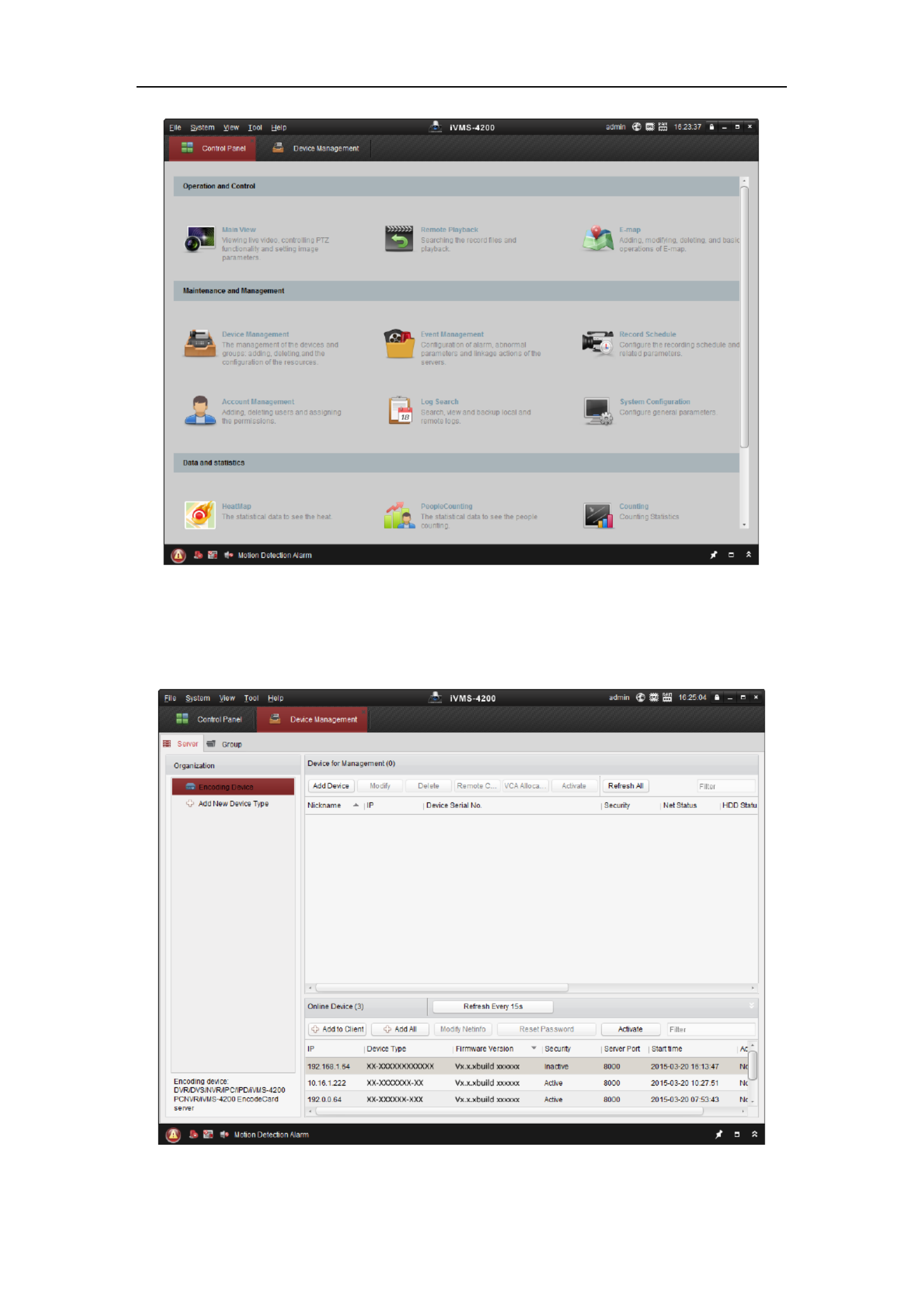
1. Run the client software and the control panel of the software pops up, as shown in
the figure below.
Network Camera User Manual
17
Figure 2-6 Control Panel
2. Click the icon to enter the Device Management interface, as Device Management
shown in the figure below.
Figure 2-7 Device Management Interface
Network Camera User Manual
18
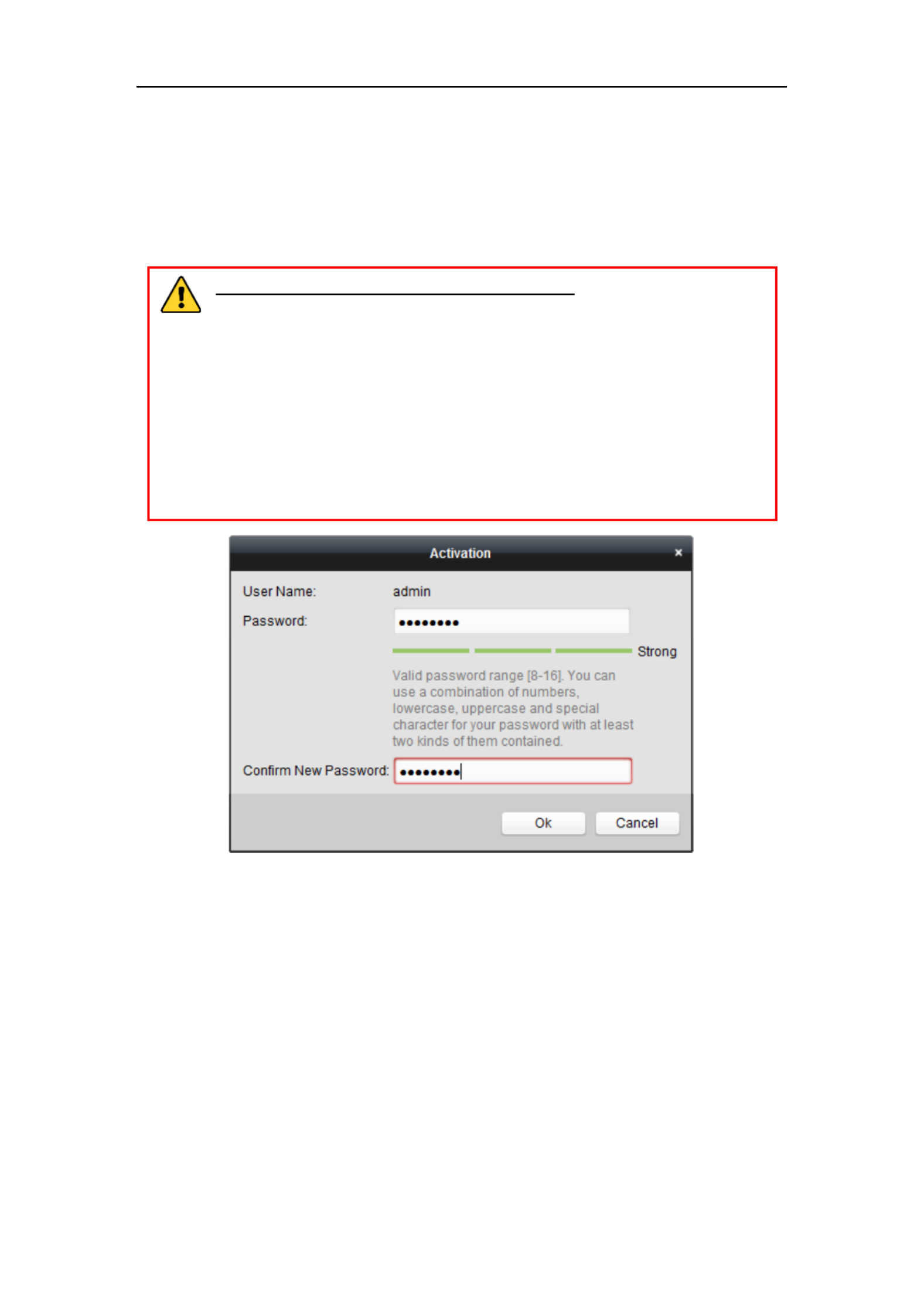
3. Check the device status from the device list, and select an inactive device.
4. Click the button to pop up the Activation interface. Activate
5. Create a password and input the password in the password field, and confirm the
password.
STRONG PASSWORD RECOMMENDED–We highly recommend
you create a strong password of your own choosing (using a minimum of
8 characters, including at least three of the following categories: upper
case letters, lower case letters, numbers, and special characters) in order
to increase the security of your product. We recommend you reset your
password regularly, especially in the high security system, resetting the
password monthly or weekly can better protect your product.
Figure 2-8 Activation Interface (Client Software)
6. Click button to start activation. OK
7. Click the Modify Netinfo button to pop up the Network Parameter Modification
interface, as shown in the figure below.

Network Camera User Manual
19
Figure 2-9 Modifying the Network Parameters
8. Change the device IP address to the same subnet with your computer by either
modifying the IP address manually or checking the checkbox of Enable DHCP.
9. Input the password to activate your IP address modification.
2.2 Setting the Network Camera over the WAN
Purpose:
This section explains how to connect the network camera to the WAN with a static IP
or a dynamic IP.
2.2.1 Static IP Connection
Before you start:
Please apply a static IP from an ISP (Internet Service Provider). With the static IP
address, you can connect the network camera via a router or connect it to the WAN
directly.
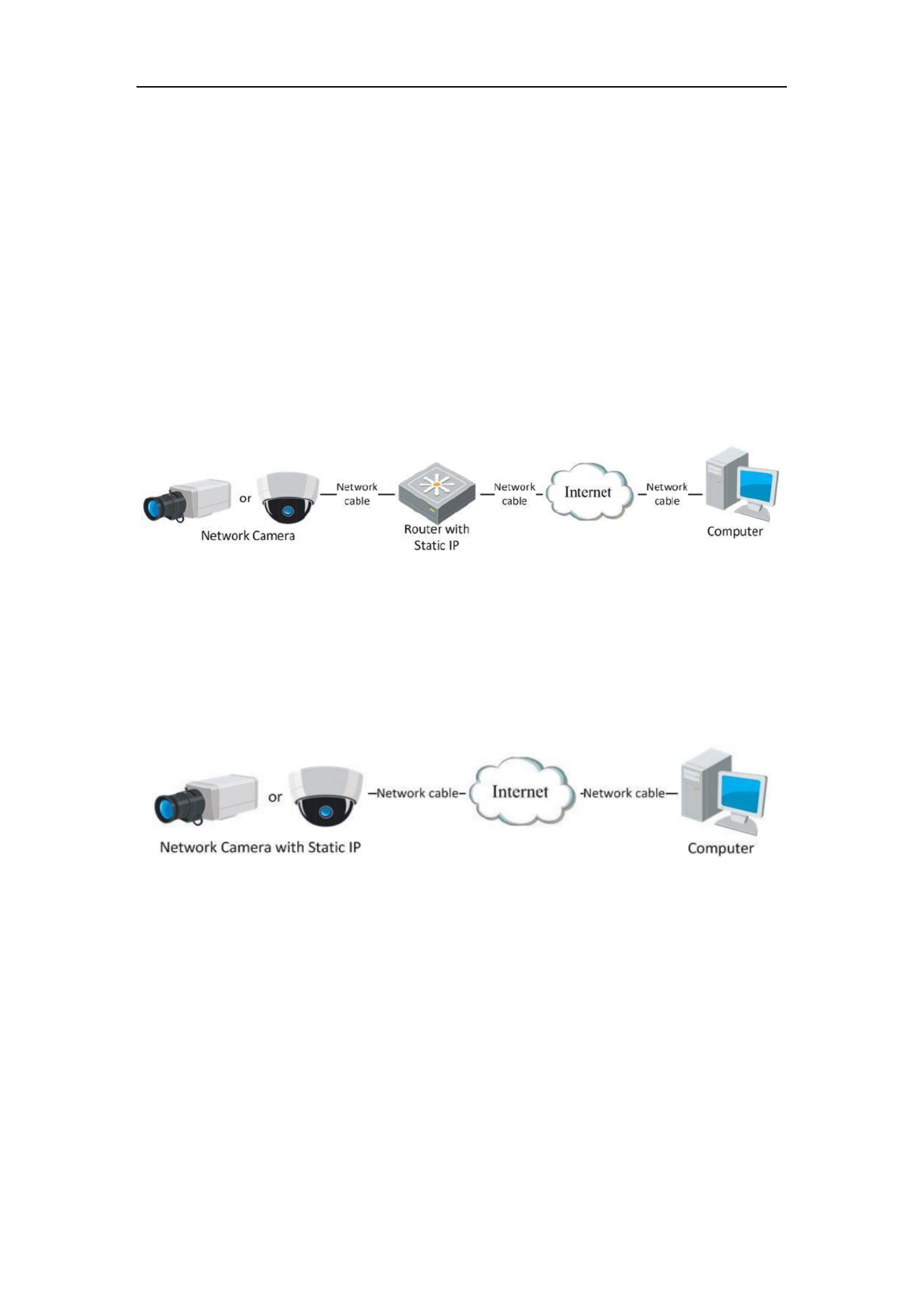
Connecting the network camera via a router
Steps:
1. Connect the network camera to the router.
Network Camera User Manual
20
2. Assign a LAN IP address, the subnet mask and the gateway. Refer to Section 2.1.2
for detailed IP address configuration of the network camera.
3. Save the static IP in the router.
4. Set port mapping, e.g., 80, 8000, and 554 ports. The steps for port mapping vary
according to the different routers. Please call the router manufacturer for
assistance with port mapping.
Note: Refer to Appendix 2 for detailed information about port mapping.
5. Visit the network camera through a web browser or the client software over the
internet.
Figure 2-10 Accessing the Camera through Router with Static IP
Connecting the network camera with static IP directly
You can also save the static IP in the camera and directly connect it to the internet
without using a router. Refer to Section 2.1.2 for detailed IP address configuration of
the network camera.
Figure 2-11 Accessing the Camera with Static IP Directly
2.2.2 Dynamic IP Connection
Before you start:
Please apply a dynamic IP from an ISP. With the dynamic IP address, you can connect
the network camera a modem or a router. to
Connecting the network camera via a router
Steps:

Network Camera User Manual
21
1. Connect the network camera to the router.
2. In the camera, assign a LAN IP address, the subnet mask and the gateway. Refer
to Section 2.1.2 for detailed IP address configuration of the network camera.
3. In the router, set the PPPoE user name, password and confirm the password.
4. Set port mapping. E.g. 80, 8000, and 554 ports. The steps for port mapping vary
depending on different routers. Please call the router manufacturer for assistance
with port mapping.
Note: Refer to Appendix 2 for detailed information about port mapping.
5. Apply a domain name from a domain name provider.
6. Configure the DDNS settings in the setting interface of the router.
7. Visit the camera via the applied domain name.
Connecting the network camera via a modem
Purpose:
This camera supports the PPPoE auto dial-up function. The camera gets a public IP
address by ADSL dial-up after the camera is connected to a modem. You need to
configure the PPPoE parameters of the network camera. Refer to Section 7.1.3
Configuring PPPoE Settings for detailed configuration.
Figure 2-12 Accessing the Camera with Dynamic IP
Note: The obtained IP address is dynamically assigned via PPPoE, so the IP address
always changes after rebooting the camera. To solve the inconvenience of the
dynamic IP, you need to get a domain name from the DDNS provider (E.g.
DynDns.com). Please follow the steps below for normal domain name resolution and
private domain name resolution to solve the problem.
Normal Domain Name Resolution

Network Camera User Manual
22
Figure 2-13 Normal Domain Name Resolution
Steps:
1. Apply a domain name from a domain name provider.
2. Configure the DDNS settings in the interface of the network DDNS Settings
camera. Refer to for detailed Section 7.1.2 Configuring DDNS Settings
configuration.
3. Visit the camera via the applied domain name.
Private Domain Name Resolution
Figure 2-14 Private Domain Name Resolution
Steps:
1. Install and run the IP Server software in a computer with a static IP.
2. Access the network camera through the LAN with web browser or the client a
software.
3. Enable DDNS and select IP Server as the protocol type. Refer to Section 7.1.2
Configuring DDNS Settings for detailed configuration.

User Manual of Network Camera
23
Chapter 3 Access to the Network
Camera
3.1 Accessing by Web Browsers
Steps:
1. Open the web browser.
2. In the browser address bar, input the IP address of the network camera, and press
the key to enter the login interface. Enter
3. Activate the network camera for the first time using, refer to the Section 2.1.2 for
details.
Note:
The default IP address is 192.168.1.64.
If the camera is not activated, please activate the camera first according to
Chapter 2.1.2.
4. Select English as the interface language on the top-right of login interface.
5. Input the user name and password and click . Login
The admin user should configure the device accounts and user/operator permissions
properly. Delete the unnecessary accounts and user/operator permissions.
Note:
The IP address gets locked if the admin user performs 7 failed password attempts
(5 attempts for the user/operator).
Figure 3-1 Login Interface
6. Install the plug-in before viewing the live video and operating the camera. Please
follow the installation prompts to install the plug- . in

Network Camera User Manual
24
Figure 3-2 Download and Install Plug- in
Note: You may have to close the web browser to install the plug-in. Please reopen
the web browser and log in again after installing the plug-in.
3.2 Accessing by Client Software
The product CD contains the iVMS-4200 client software. You can view the live video
and manage the camera with the software.
Follow the installation prompts to install the software. The control panel and live view
interface of iVMS-4200 client software are shown as below.
Figure 3-3 iVMS-4200 Control Panel

Network Camera User Manual
25
Figure 3-4 iVMS-4200 Main View
Network Camera User Manual
26
Chapter 4 -Fi Settings Wi
Purpose:
By connecting to the wireless network, you don’t need to use cable of any kind for
network connection, which is very convenient for the actual surveillance application.
Note: This chapter is only applicable for the cameras with the built-in Wi-Fi module.
4.1 Configuring Wi-Fi Connection in Manage and
Ad-hoc Modes
Purpose:
Two connection modes are supported. Choose a mode as desired and perform the
steps to configure the Wi-Fi.
Wireless Connection in Manage Mode
Steps:
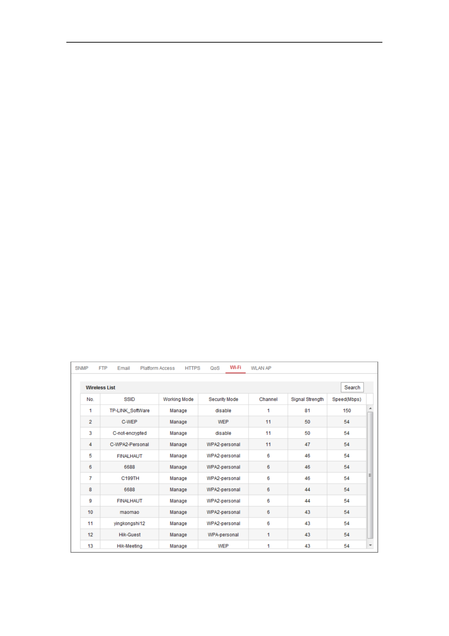
1. Enter the Wi-Fi configuration interface.
Configuration> Network> Advanced Settings> - Wi Fi
2. Click Search to search the online wireless connections.
Figure 4-1 -Fi List Wi

Network Camera User Manual
27
3. Click to choose a wireless connection on the list.
Figure 4-2 -Fi Setting- Manage Mode Wi
4. Check the radio button to select the and the Network mode as Manage,
Security mode of the network is automatically shown when you select the
wireless network, please don’t change it manually.
Note: These parameters are exactly identical with those of the router.
5. Enter the key to connect the wireless network. The key should be that of the
wireless network connection you set on the router.
Wireless Connection in Ad-hoc Mode
If you choose the Ad-hoc mode, you don’t need to connect the wireless camera via a
router. The scenario is the same as you connect the camera and the PC directly with a
network cable.
Steps:
1. Choose Ad-hoc mode.
Figure 4-3 -Fi Setting- Wi Ad-hoc

Network Camera User Manual
28
2. Customize a SSID for the camera.
3. Choose the Security Mode of the wireless connection.
4. Enable the wireless connection function for your PC.
5. On the PC side, search the network and you can see the SSID of the camera
listed.
Figure 4-4 -hoc Connection Point Ad
6. Choose the SSID and connect.
Security Mode Description:
Figure 4-5 Security Mode
You can choose the Security Mode as not-encrypted, WEP, WPA-personal,
WPA-enterprise, WPA2-personal, and WPA2-enterprise.
WEP mode:

Network Camera User Manual
29
Figure 4-6 WEP Mode
Authentication - Select Open or Shared Key System Authentication, depending on
the method used by your access point. Not all access points have this option, in
which case they probably use Open System, which is sometimes known as SSID
Authentication.
Key length - This sets the length of the key used for the wireless encryption, 64 or
128 bit. The encryption key length can sometimes be shown as 40/64 and
104/128.
Key type The key types available depend on the access point being used. The -
following options are available:
HEX - Allows you to manually enter the hex key.
ASCII - In this method the string must be exactly 5 characters for 64-bit WEP and
13 characters for 128-bit WEP.
WPA-personal and WPA2-personal Mode:
Enter the required Pre-shared Key for the access point, which can be a hexadecimal
number or a passphrase.
Figure 4-7 Security Mode- WPA-personal
WPA- enterprise and WPA2-enterprise Mode:

Network Camera User Manual
30
Choose the type of client/server authentication being used by the access point;
EAP-TLS or EAP-PEAP.
EAP-TLS
Figure 4-8 EAP-TLS
Identity - Enter the user ID to present to the network.
Private key password Enter the password for your user ID. –
EAPOL version - Select the version used (1 or 2) in your access point.
CA Certificates - Upload a CA certificate to present to the access point for
authentication.
EAP-PEAP:
User Name - Enter the user name to present to the network
Password - Enter the password of the network
PEAP Version - Select the PEAP version used at the access point.
Label - Select the label used by the access point.
EAPOL version - Select version (1 or 2) depending on the version used at the
access point
CA Certificates - Upload a CA certificate to present to the access point for
authentication
For your privacy and to better protect your system against security risks, we

Network Camera User Manual
31
strongly recommend the use of strong passwords for all functions and network
devices. The password should be something of your own choosing (using a
minimum of 8 characters, including at least three of the following categories:
upper case letters, lower case letters, numbers and special characters) in order to
increase the security of your product.
Proper configuration of all passwords and other security settings is the
responsibility of the installer and/or end-user.
4.2 Easy Wi-Fi Connection with WPS function
Purpose:
The setting of the wireless network connection is never easy. To avoid the complex
setting of the wireless connection you can enable the WPS function.
WPS (Wi-Fi Protected Setup) refers to the easy configuration of the encrypted
connection between the device and the wireless router. The WPS makes it easy to add
new devices to an existing network without entering long passphrases. There are two
modes of the WPS connection, the PBC mode and the PIN mode.
Note: If you enable the WPS function, you do not need to configure the parameters
such as the encryption type and you don’t need to know the key of the wireless
connection.
Steps:
Figure 4-9 -Fi Settings - WPS Wi

Network Camera User Manual
32
PBC Mode:
PBC refers to the Push-Button-Configuration, in which the user simply has to push a
button, either an actual or virtual one (as the button on the configuration
interface of the IE browser), on both the Access Point (and a registrar of the network)
and the new wireless client device.
1. Check the checkbox of to enable WPS.
2. Choose the connection mode as PBC.
Note: Support of this mode is mandatory for both the Access Points and the
connecting devices.
3. Check on the Wi-Fi router to see if there is a WPS button. If yes push the button
and you can see the indicator near the button start flashing, which means the WPS
function of the router is enabled. For detailed operation, please see the user guide of
the router.
4. Push the WPS button to enable the function on the camera.
If there is not a WPS button on the camera, you can also click the virtual button to
enable the PBC function on the web interface.
5. Click button. Connect
When the PBC mode is both enabled in the router and the camera, the camera and the
wireless network is connected automatically.
PIN Mode:
The PIN mode requires a Personal Identification Number (PIN) to be read from either
a sticker or the display on the new wireless device. This PIN must then be entered to
connect the network, usually the Access Point of the network.
Steps:
1. Choose a wireless connection on the list and the SSID is loaded automatically.
2. Choose Use route PIN code.

Network Camera User Manual
33
Figure 4-10 Use PIN Code
If the PIN code is generated from the router side, you should enter the PIN code you
get from the router side in the Router PIN code field.
3. Click . Connect
Or
You can generate the PIN code on the camera side. And the expired time for the PIN
code is 120 seconds.
1. Click . Generate
2. Enter the code to the router, in the example, enter 48167581 to the router.
4.3 IP Property Settings for Wireless Network
Connection
The default IP address of wireless network interface controller is 192.168.1.64. When
you connect the wireless network you can change the default IP.
Steps:
1. Enter the TCP/IP configuration interface.
Configuration> Network> Basic Settings > TCP/IP
2. Select the Wlan tab.

Network Camera User Manual
34
Figure 4-11 Setting WLAN Parameters
3. Customize the IPv4 address, the IPv4 Subnet Mask and the Default Gateway.
The setting procedure is the same with that of LAN.
If you want to be assigned the IP address you can check the checkbox to enable
the DHCP.

User Manual of Network Camera
35
Chapter 5 Live View
5.1 Live View Page
Purpose:
The live view page allows you to view the real-time video, capture images, realize
PTZ control, set/call presets and configure video parameters.
Log the network camera to enter the live view page, or you can click in Live View on
the menu bar of the main page to enter the live view page.
Descriptions of the live view page:
Toolbar
Live View
Window
Menu Bar
PTZ Control
Panel
Preset/Patrol
Sengs
Figure 5-1 Live View Page
Menu Bar:
Click each tab to enter Live View, Playback, Picture, Application, d Configuration an
page respectively.
Live View Window:
Display the live video.
Toolbar:
Toolbar allows you to adjust the live view window size, the stream type, and the
plug- s. It also allows you to process the operations on the live view page, e.g., in
start/stop live view, capture, record, audio on/off, two-way audio, start/stop digital
zoom, etc.

Network Camera User Manual
36
For IE (Internet Explorer) users, plug-ins webcomponents and quick time are as
selectable. And for Non-IE users, webcomponents, quick time, VLC or MJPEG is
selectable if they are supported by the web browser.
PTZ Control:
Perform panning, tilting and zooming actions of the camera. Control the light and the
wiper (only available for cameras supporting PTZ function).
Preset/Patrol Settings :
Set/call/delete the presets or patrols for PTZ cameras.
5.2 Starting Live View
In the live view window as shown in Figure 4-2, click on the toolbar to start the
live view of the camera.
Figure 5-2 Live View Toolbar
Table 5-1 Descriptions of the Toolbar
Icon
Description
/
Start/Stop live view.
The window size is 4:3.
The window size is 16:9.
The original widow size.
Self-adaptive window size.
Live view with the main str . eam
Live view with the sub stream.
Live view with the third stream.
Click to select the third-party plug-in.
Manually capture the picture.
/
Manually start/stop recording.
/
Audio on and adjust volume /Mute.
/
Turn on/off microphone.
/
Start/stop digital zoom function.
Note: The icons vary according to the different camera models.

Network Camera User Manual
37
5.3 Recording and Capturing Pictures Manually
In the live view interface, click on the toolbar to capture the live pictures or click
to record the live view. The saving paths of the captured pictures and clips can be
set on the page. To configure remote scheduled recording, Configuration > Local
please refer to . Section 6.1
Note: The captured image will be saved as JPEG file or BMP file your computer. in
5.4 Operating PTZ Control
Purpose:
In the live view interface, you use the PTZ control buttons to realize pan/tilt/zoom can
control of the camera.
Note: To realize PTZ control, the camera connected to the network must support the
PTZ function or have a pan/tilt unit installed to the camera. Please properly set the
PTZ parameters on RS485 s tings page referring et to Section 6.2.4 .RS485 Settings
5.4.1 PTZ Control Panel
On the live view page, click next to the right side of the live view window to show
the PTZ control panel and click to hide . it
Click the direction buttons to control the pan/tilt movements.
Figure 5-3 PTZ Control Panel

Network Camera User Manual
38
Click the zoom/focus/iris buttons to realize lens control.
Notes:
There are eight direction arrows ( , , , , , , , in the control )
panel. Click the arrows to realize adjustment in the relative positions.
For the cameras which support lens movements only, the direction buttons are
invalid.
Table 5-2 Descriptions of PTZ Control Panel
Icon
Description
Zoom in/out
Focus near/far
Iris / + -
PTZ speed adjustment
Light on/off
Wiper on/off
Auxiliary focus
Initialize lens
Adjust speed of pan/tilt movements
Start Manual Tracking
Start 3D Zoom
5.4.2 Setting/Calling a Preset
Setting a Preset:
1. In the PTZ control panel, select a preset number from the preset list.
Figure 5-4 Setting a Preset

Network Camera User Manual
39
2. Use the PTZ control buttons to move the lens the desired position. to
• Pan the camera to the right or left.
• Tilt the camera up or down.
• Zoom in or out.
• Refocus the lens.
3. Click to finish the setting of the current preset.
4. You can click to delete the preset.
Calling a Preset:
This feature enables the camera to point to a specified preset scene manually or when
an event takes place.
For the defined preset, you can call it at any time to the desired preset scene.
In the PTZ control panel, select a defined preset from the list and click to call the
preset.
Or you can place the mouse on the presets interface, and call the preset by typing the
preset No. to call the corresponding presets.
Figure 5-5 Calling a Preset
5.4.3 Setting/Calling a Patrol
Note:
No less than 2 presets have to be configured before you set a patrol.
Steps:
1. Click to enter the patrol configuration interface.
2. Select a path No., and click to add the configured presets.

Network Camera User Manual
40
3. Select the preset, and input the patrol duration and patrol speed.
4. Click OK to save the first preset.
5. Follow the steps above to add the other presets.
Figure 5-6 Add Patrol Path
6. Click to save a patrol. OK
7. Click to start the patrol, and click to stop it.
8. (Optional) Click to delete a patrol.
User Manual of Network Camera
41
Chapter 6 Network Camera
Configuration
6.1 Configuring Local Parameters
Purpose:
The local configuration refers to the parameters of the live view, record files and
captured pictures. The record files and captured pictures are the ones you record and
capture using the web browser and thus the saving paths of them are on the PC
running the browser.
Steps:
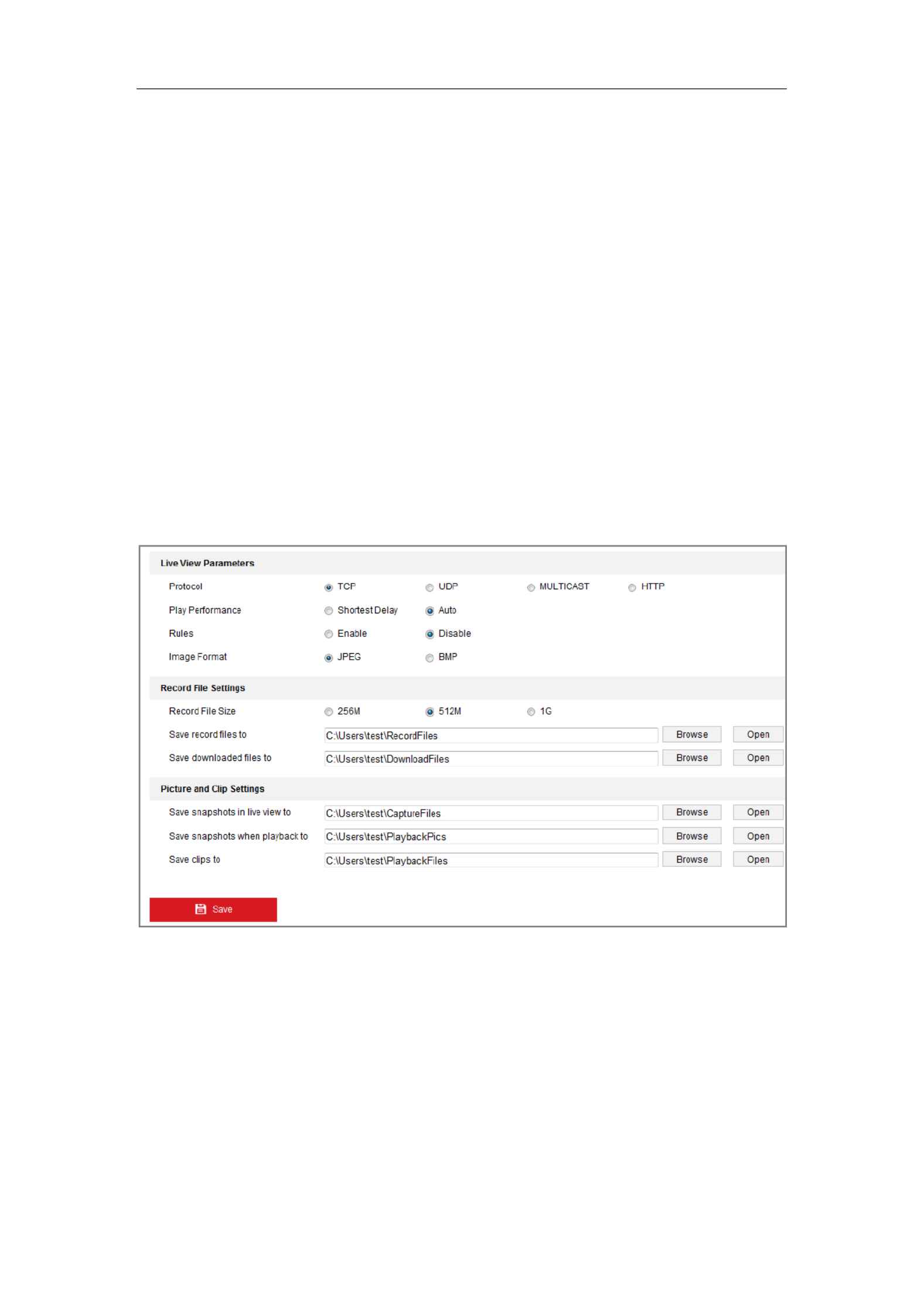
1. Enter the Local Configuration interface: > . Configuration Local
Figure 6-1 Local Configuration Interface
2. Configure the following settings:
Live View Parameters: Set the protocol type and live view performance.
Protocol Type: TCP, UDP, MULTICAST and HTTP are selectable.
TCP: Ensures complete delivery of streaming data and better video quality,
yet the real-time transmission will be affected.
UDP: Provides real-time audio and video streams.
Network Camera User Manual
43
6.2 Configure System Settings
Purpose:
Follow the instructions below to configure the system settings, include System
Settings, Maintenance, Security, and User Management, etc.
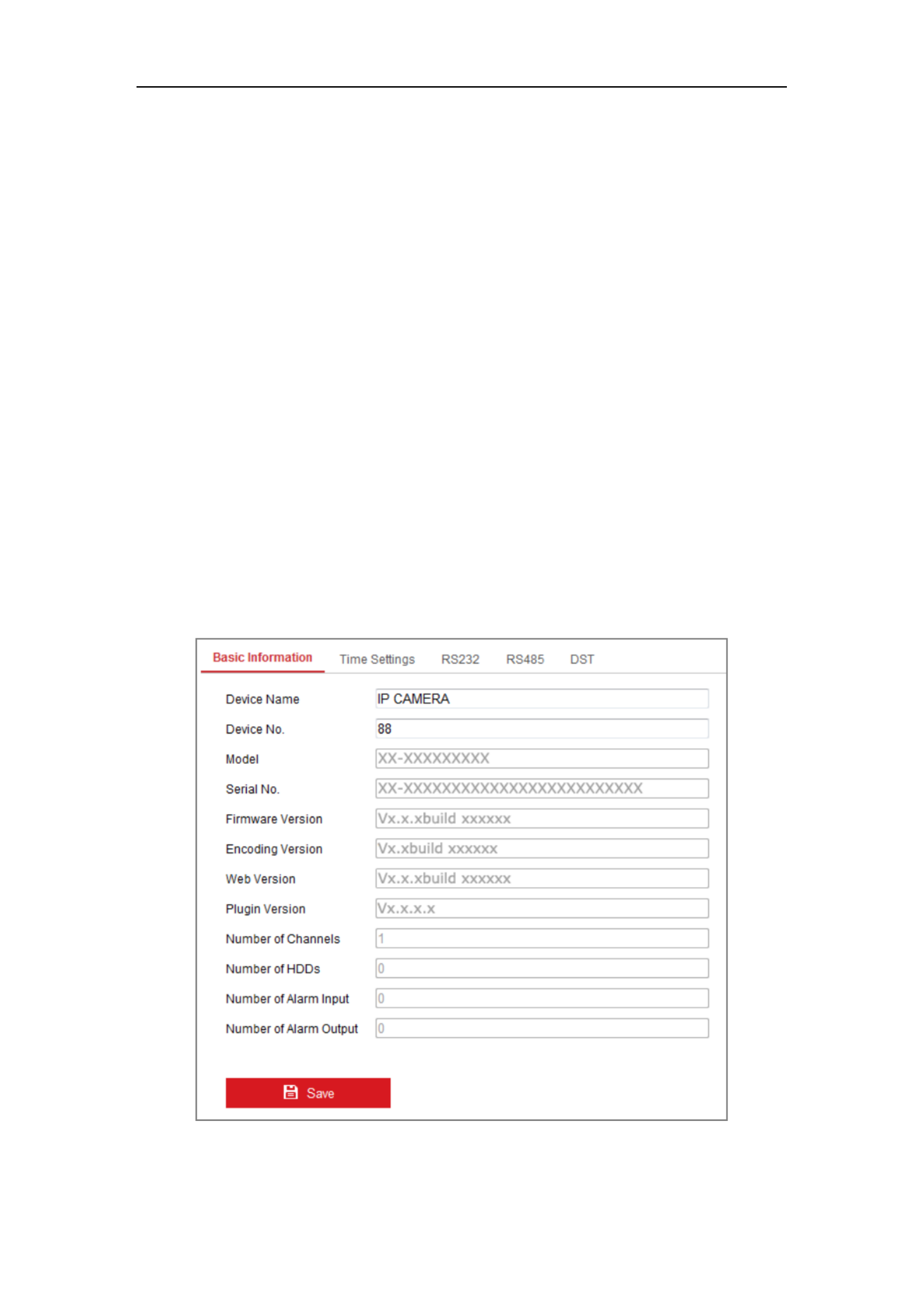
6.2.1 Configuring Basic Information
Enter the Device Information interface: Configuration > System > System
Settings Basic Information > .
In the interface, you can edit the Device Name and Device No.. Basic Information
Other information of the network camera, such as Model, Serial No., Firmware
Version, Encoding Version, Number of Channels, Number of HDDs, Number of
Alarm Input and Number of Alarm Output are displayed. The information cannot be
changed in this menu. It is the reference for maintenance or modification in future.
Figure 6-2 Basic formation In

Network Camera User Manual
44
Online Upgrade
For some camera models, when memory card is mounted, you can click the Update
button that appears on the right of Firmware Version text field to see if there is a new
version available. If a new version is available, the version number will be displayed
in the New Version text field below, and you can click the button to upgrade Upgrade
the firmware for the camera.
Figure 6-3 Online Upgrade
Note: When the camera is upgrading, don't power off the camera. During upgrading,
the camera may not be accessible. You need to wait 1 or 2 minutes before the upgrade
finishes.
6.2.2 Configuring Time Settings
Purpose:
You can follow the instructions in this section to configure the time synchronization
and DST settings.
Steps:
1. ter the Time Settings interface, En Configuration > System> System Settings >
Time Settings .

Network Camera User Manual
45
Figure 6-4 Time Settings
2. Select the Time Zone of your location from the drop-down menu.
3. Configure the NTP settings.
(1) Click to enable the function. NTP
(2) Configure the following settings:
Server Address: IP address of NTP server.
NTP Port: Port of NTP server.
Interval: The time interval between the two synchronizing actions with NTP
server.
(3) (Optional) You can click the Test button to test the time synchronization
function via NTP server.
Figure 6-5 Time Sync by NTP Server

Network Camera User Manual
46
Note: If the camera is connected to a public network, you should use a NTP server
that has a time synchronization function, such as the server at the National Time
Center (IP Address: 210.72.145.44). If the camera is set in a customized network,
NTP software can be used to establish a NTP server for time synchronization.
Configure the manual time synchronization.
(1) Check the Manual Time Sync. item to enable the manual time
synchronization function.
(2) Click the icon select the date, time from the pop-up calendar. to
(3) (Optional) You can check Sync. with computer time item to synchronize the
time of the device with that of the local PC.
Figure 6-6 Time Sync Manually
Click to save the settings. Save
6.2.3 Configuring RS232 Settings
The RS232 port can be used in two ways:
Parameters Configuration: Connect a computer to the camera through the serial
port. Device parameters can be configured by using software such as
HyperTerminal. The serial port parameters must be the same as the serial port
parameters of the camera.
Transparent Channel: Connect a serial device directly to the camera. The serial
device will be controlled remotely by the computer through the network.

Network Camera User Manual
47
Steps:
1. Enter RS232 Port Setting interface: Configuration> System > System Settings >
RS232.
2. Configure the Baud Rate, Data Bit, Stop Bit, Parity, Flow Control, and Usage.
Figure 6-7 RS232 Settings
Note: If you want to connect the camera by the RS232 port, the parameters of the
RS232 should be exactly the same with the parameters you configured here.
3. Click to save the settings. Save
6.2.4 Configuring RS485 Settings
Purpose:
The RS485 serial port is used to control the PTZ of the camera. The configuring of
the PTZ parameters should be done before you control the PTZ unit.
Steps:
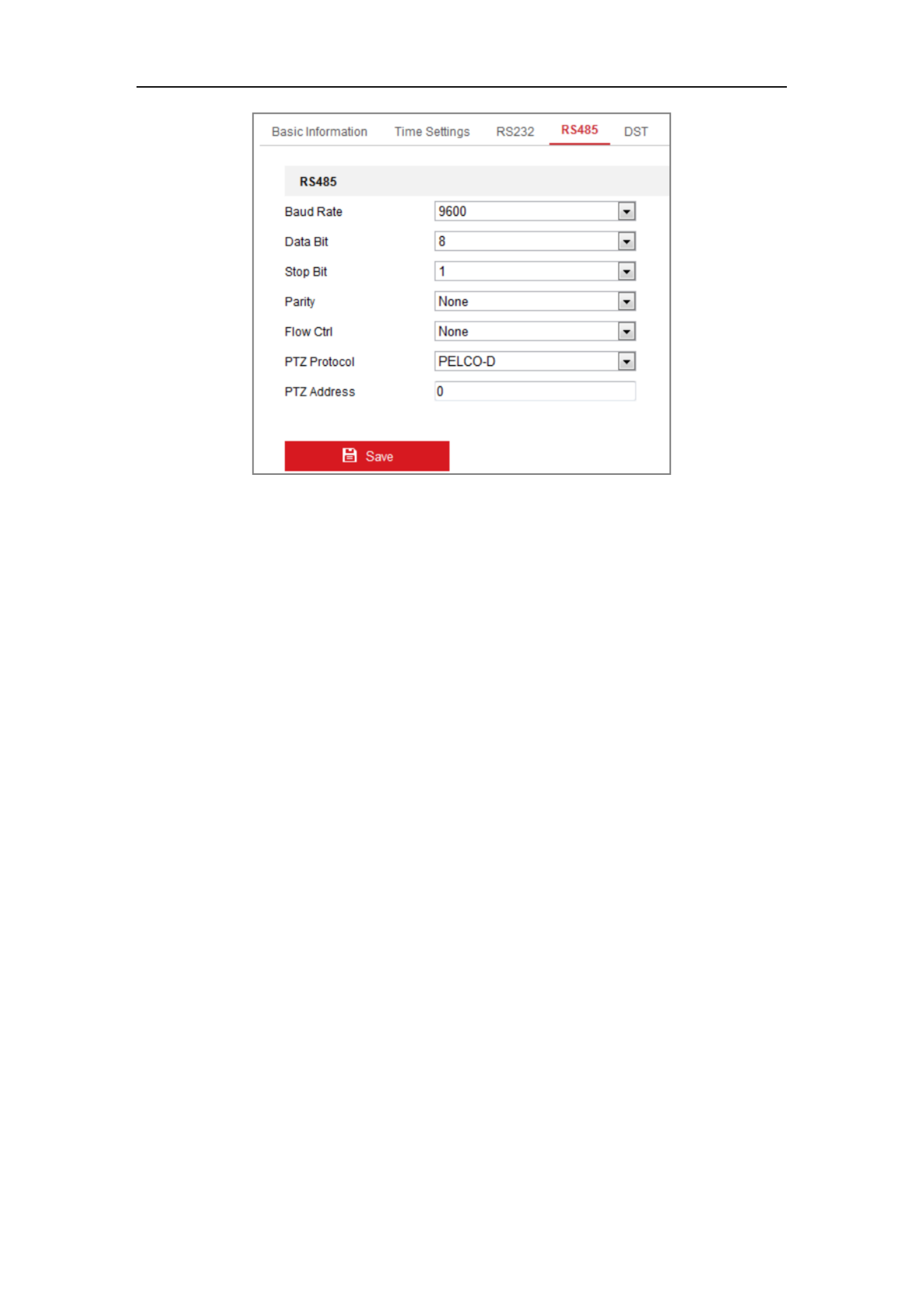
1. Enter RS-485 Port Setting interface: Configuration > System > System
Settings 485 > RS .
Network Camera User Manual
48
Figure 6-8 -485 Settings RS
2. Set the RS485 parameters and click to save the settings. Save
By default, the Baud Rate is set as 9600 bps, the Data Bit is 8, the stop bit is 1 and
the Parity and Flow Control is None.
Note: The Baud Rate, PTZ Protocol and PTZ Address parameters should be exactly
the same as the PTZ camera parameters.
6.2.5 Configuring DST Settings
Purpose:
Daylight Saving Time (DST) is a way of making better use of the natural daylight by
setting your clock forward one hour during the summer months, and back again in the
fall.
Configure the DST according to your actual demand.
Steps:
1. Enter the DST configuration interface.
Configuration System System Settings DST> > >

Network Camera User Manual
49
Figure 6-9 DST Settings
2. Select the start time and the end time.
3. Select the DST Bias.
4. Click to activate the settings. Save
6.2.6 Configuring External Devices
Purpose:
For the device supported external devices, including the wiper on the housing or the
LED light, you can control them via the Web browser. External devices vary
according to the different camera models.
Steps:
1. Enter the External Device configuration interface.
Configuration System System Settings External Device > > >
Figure 6-10 External Device Settings
2. Check the Enable Supplement Light checkbox to enable the LED Light.
3. Move the slider to adjust the low beam brightness and high bean brightness.
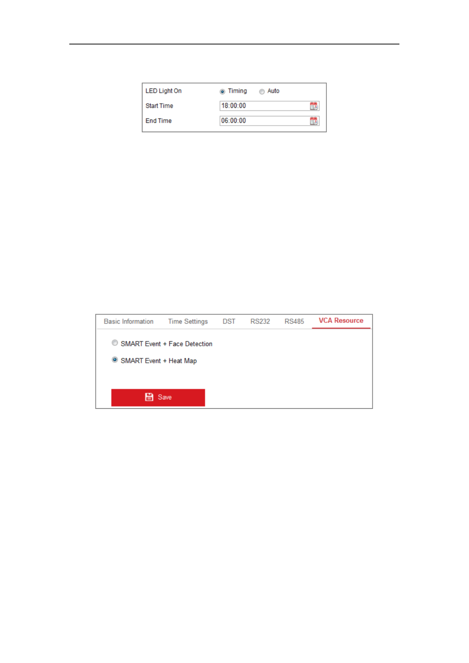
4. Select the mode for LED light. Timing and Auto are selectable.
Timing: The LED will be turned on by the schedule you set. You should set
Network Camera User Manual
50
the Start Time and End Time.
Figure 6-11 Set Schedule
Auto: The LED will be turned on according to the environment illumination.
5. Click Save to save the settings.
6.2.7 Configuring VCA Resource
Purpose:
VCA resource offers you options to enable certain VCA functions according to actual
need when several VCA functions are available. It helps allocate more resources to
the wanted functions.
Figure 6-12 VCA Resource Configuration
Steps:
1. Enter VCA Resource configuration interface:
Configuration > System > System Settings > VCA Resource
2. Select a desired VCA combination. SMART Event + Face Detection and SMART
Event + Heat Map are selectable.
3. Click to save the settings. A reboot is required after setting the VCA Save
Resource.
Notes:
• VCA Resource function varies according to different camera models.

Network Camera User Manual
51
• Face Detection and Heat Map are mutually exclusive. When SMART Event +
Heat Map is enabled, Face Detection interface will not be displayed.
• The function may not be supported by some camera models.
6.3 Maintenance
6.3.1 Upgrade & Maintenance
Purpose:
The upgrade & maintenance interface allows you to process the operations, including
reboot, partly restore, restore to default, export/import the configuration files, and
upgrade the device.
Enter the Maintenance interface: Configuration > System > Maintenance >
Upgrade & Maintenance.
Reboot: Restart the devi ce.
Restore: Reset all the parameters, except the IP parameters and user information,
to the default settings.
Default: Restore all the parameters to the factory default.
Note: After restoring the default settings, the IP address is also restored to the default
IP address, please be careful for this action.
Export/Import Config. File: Configuration file is used for the batch
configuration of the camera, which can simplify the configuration steps when
there are a lot of cameras needing configuring.
Steps:
1. Click Device Parameters to export the current configuration file, and save it
to certain place.
2. Click Browse Importto select the saved configuration file and then click to
start importing configuration file.
Note: You need to reboot the camera after importing configuration file.
Upgrade: Upgrade the device to a certain version.

Network Camera User Manual
52
Steps:
1. Select firmware or firmware directory to locate the upgrade file.
Firmware: Locate the exact path of the upgrade file.
Firmware Directory: Only the directory the upgrade file belongs to is
required.
2. Click to select the local upgrade file and then click to start Browse Upgrade
remote upgrade.
Note: e upgrading process will take 1 to 10 minutes. Please don't disconnect Th
power of the camera during the process, and the camera reboots automatically
after upgrade.
6.3.2 Log
Purpose:
The operation, alarm, exception and information of the camera can be stored in log
files. You can also export the log files on your demand.
Before you start:
Please configure network storage for the camera or insert a SD card in the camera.
Steps:
1. Enter log searching interface . : Configuration > System > Maintenance > Log
Figure 6-13 Log Searching Interface
2. Set the log search conditions to specify the search, including the Major Type,
Minor Type, Start Time and End Time.
3. Click Search to search log files. The matched log files will be displayed on the
log list interface.

Network Camera User Manual
53
Figure 6-14 Log Searching
4. To export the log files, click to save the log files. Export
6.3.3 System Service
Purpose:
System service settings refer to the hardware service the camera supports. Supported
functions vary according to the different cameras. For the cameras support IR LED,
ABF (Auto Back Focus), Auto Defog, or Status LED, you can select to enable or
disable the corresponding service according to the actual demands.
ABF: When ABF function is enabled, you can click on PTZ control panel to
realize auxiliary focus.
6.4 Security Settings
Configure the parameters, including Authentication, Anonymous Visit, IP Address
Filter, and Security Service from security interface.

Network Camera User Manual
54
6.4.1 Authentication
Purpose:
You can specifically secure the stream data of live view.
Steps:
1. Enter the Authentication interface: Configuration > System > Security >
Authentication.
Figure 6-15 RTSP Authentication
2. Select the RTSP type or in the drop-down list to Authentication basic disable
enable or disable the RTSP authentication.
Note: If you disable the RTSP authentication, anyone can access the video stream by
the RTSP protocol via the IP address.
3. Click to save the settings. Save
6.4.2 IP Address Filter
Purpose:
This function makes it possible for access control.
Steps:
1. Enter the IP Address Filter interface: Configuration > System > Security > IP
Address Filter

Network Camera User Manual
55
Figure 6-16 IP Address Filter Interface
2. Check the checkbox of Enable IP Address Filter.
3. Select the type of IP Address Filter in the drop-down list, and Forbidden Allowed
are selectable.
4. Set the IP Address Filter list.
Add an IP Address
Steps:
(1) Click the to add an IP. Add
(2) Input the IP Adreess.
Figure 6-17 Add an IP
(3) Click the to finish adding. OK
Modify an IP Address
Steps:
(1) Left-click an IP address from filter list and click . Modify
(2) Modify the IP address in the text filed.
Figure 6-18 Modify an IP

Network Camera User Manual
56
(3) Click the to finish modifying. OK
Delete an IP Address or IP Addresses.
Select the IP address(es) and click . Delete
5. Click to save the settings. Save
6.4.3 curity Service Se
To enable the remote login, and improve the data communication security, the camera
provides the security service for better user experience.
Steps:
1. Enter the security service configuration interface : Configuration > System >
Security Security Service > .
Figure 6-19 Security Service
2. Check the checkbox of to enable the data communication security, Enable SSH
and uncheck the checkbox to disable the SSH.
3. Check the checkbox of , and then the IP address will Enable Illegal Login Lock
be locked if the admin user performs 7 failed user name/password attempts (5
times for the operator/user).
Note: If the IP address is locked, you can try to login the device after 30 minutes.

Network Camera User Manual
58
● STRONG PASSWORD RECOMMENDED–We highly recommend you
create a strong password of your own choosing (using a minimum of 8
characters, including at least three of the following categories: upper case
letters, lower case letters, numbers, and special characters) in order to
increase the security of your product. And we recommend you reset your
password regularly, especially in the high security system, resetting the
password monthly or weekly can better protect your product.
3. you can check or uncheck the permissions for the new user.
4. Click to finish the user addition. OK
Figure 6-21 Add a User
Modifying a User
Steps:
1. Left-click to select the user from the list and click . Modify
2. Modify the User Name Level Password, and .

Network Camera User Manual
59
3. STRONG PASSWORD RECOMMENDED–We highly recommend you
create a strong password of your own choosing (using a minimum of 8
characters, including at least three of the following categories: upper case
letters, lower case letters, numbers, and special characters) in order to
increase the security of your product. And we recommend you reset your
password regularly, especially in the high security system, resetting the
password monthly or weekly can better protect your product.
4. You can check or uncheck the permissions.
5. Click to finish the user modification. OK
Figure 6-22 Modify a User
Deleting a User
Steps:
1. Click to select the user you want to delete and click . Delete
2. Click on the pop-up dialogue box to confirm the deletion. OK

Network Camera User Manual
60
6.5.2 Online Users
Purpose:
You can see the current users who are visiting the device through this interface. User
information, such as user name, level, IP address, and operation time, is displayed in
the User List.
Click Refresh to refresh the list.
Figure 6-23 View the Online Users

User Manual of Network Camera
61
Chapter 7 Network Settings
Purpose:
Follow the instructions in this chapter to configure the basic settings and advanced
settings.
7.1 Configuring Basic Settings
Purpose:
You can configure the parameters, including TCP/IP, DDNS, PPPoE, Port, and NAT,
etc., by following the instructions in this section.
7.1.1 Configuring TCP/IP Settings
Purpose:
TCP/IP settings must be properly configured before you operate the camera over
network. The camera supports both the IPv4 and IPv6. Both versions be can
configured simultaneously without conflicting to each other, and at least one IP
version should be configured.
Steps:
1. Enter TCP/IP Settings interface: Configuration > Network > Basic
Settings > TCP/IP

Network Camera User Manual
62
Figure 7-1 TCP/IP Settings
2. Configure the basic network settings, including the NIC Type, IPv4 or IPv6
Address, IPv4 or IPv6 Subnet Mask, IPv4 or IPv6 Default Gateway, MTU settings
and Multicast Address.
3. (Optional) Check the checkbox of , and then the Enable Multicast Discovery
online network camera can be automatically detected by client software via
private multicast protocol in the LAN.
4. Configure the DNS server. Input the preferred DNS server, and alternate DNS
server.
5. Click to save the above settings Save .
Notes :
The valid value range of MTU is 1280 ~ 1500.
The Multicast sends a stream to the multicast group address and allows multiple
clients to acquire the stream at the same time by requesting a copy from the

Network Camera User Manual
63
multicast group address. Before utilizing this function, you have to enable the
Multicast function of your router.
A reboot is required for the settings to take effect.
7.1.2 Configuring DDNS Settings
Purpose:
If your camera is set to use PPPoE as its default network connection, you can use the
Dynamic DNS (DDNS) for network access.
Before you start:
Registration on the DDNS server is required before configuring the DDNS settings of
the camera.
Steps:
1. Enter the DDNS Settings interface: Configuration > Network > Basic
Settings > DDNS.
2. Check the checkbox to enable this feature. Enable DDNS
3. Select . Four DDNS types are selectable: HiDDNS, IPServer, DDNS Type
DynDNS and NO-IP.
DynDNS:
Steps:
(1) Enter of DynDNS (e.g. members.dyndns.org). Server Address
(2) In the text field, enter the domain name obtained from the DynDNS Domain
website.
(3) Enter the and registered on the DynDNS website. User Name Password
(4) Click to save the settings. Save

Network Camera User Manual
64
Figure 7-2 DynDNS Settings
IP Server:
Steps:
(1) Enter the Server Address of the IP Server.
(2) Click to save the settings. Save
Figure 7-3 IPServer Settings
Note:
• For the IP Server, you have to apply a static IP, subnet mask, and gateway
and preferred DNS from the ISP. The should be entered Server Address
with the static IP address of the computer that runs the IP Server software.
• For the US and Canada area, you can enter 173.200.91.74 as the server
address.

Network Camera User Manual
65
NO-IP:
Steps:
(1) Choose the DDNS Type as NO-IP.
Figure 7-4 -IP DNS Settings NO
(2) Enter the Server Address as www.noip.com
(3) Enter the Domain name you registered.
(4) Enter the User Name and Password.
(5) Click and then you can view the camera with the domain name. Save
HiDDNS
Steps:
(1) Choose the DDNS Type as HiDDNS.
Figure 7-5 HiDDNS Settings
(1) Enter the Server Address www.hik-online.com.

Network Camera User Manual
66
(2) Enter the Domain name of the camera. The domain is the same with the
device alias in the HiDDNS server.
(3) Click to save the new settings. Save
Note: Reboot the device to make the settings take effect.
7.1.3 Configuring PPPoE Settings
Steps:
1. Enter the PPPoE Settings interface: Configuration > Network > Basic
Settings > PPPoE
Figure 7-6 PPPoE Settings
2. Check the checkbox to enable this feature. Enable PPPoE
3. Enter , , and password for PPPoE access. User Name Password Confirm
Note: The User Name and Password should be assigned by your ISP.
For your privacy and to better protect your system against security risks, we
strongly recommend the use of strong passwords for all functions and network
devices. The password should be something of your own choosing (using a
minimum of 8 characters, including at least three of the following categories:
upper case letters, lower case letters, numbers and special characters) in order to
increase the security of your product.
Proper configuration of all passwords and other security settings is the
responsibility of the installer and/or end-user.

Network Camera User Manual
67
4. Click to save and exit the interface. Save
Note: A reboot is required for the settings to take effect.
7.1.4 Configuring Port Settings
Purpose:
You can set the port No. of the camera, e.g., HTTP port, RTSP port and HTTPS port.
Steps:
1. ter the Port Settings interface, En Configuration > Network > Basic Settings >
Port
Figure 7-7 Port Settings
2. Set the HTTP port, RTSP port, HTTPS port and server port of the camera.
HTTP Port: The default port number is 80, and it can be changed to any port No.
which is not occupied.
RTSP Port: The default port number is 554 and it can be changed to any port No.
ranges from 1 to 65535.
HTTPS Port: The default port number is 443, and it can be changed to any port
No. which is not occupied.
Server Port: The default server port number is 8000, and it can be changed to
any port No. ranges from 2000 to 65535.
3. Click to save the settings. Save
Note: A reboot is required for the settings to take effect.

Network Camera User Manual
68
7.1.5 Configure NAT (Network Address Translation) Settings
Purpose:
NAT interface allows you to configure the UPnP parameters. ™
Universal Plug and Play (UPnP™) is a networking architecture that provides
compatibility among networking equipment, software and other hardware devices.
The UPnP protocol allows devices to connect seamlessly and to simplify the
implementation of networks in the home and corporate environments.
With the function enabled, you don’t need to configure the port mapping for each port,
and the camera is connected to the Wide Area Network via the router.
Steps:
1. Enter the NAT settings interface. Configuration > Network > Basic Settings >
NAT.
2. C heck the checkbox to enable the UPnP™ function.
3. Choose a nickname for the camera, or you can use the default name.
4. Select the port mapping mode. Manual and Auto are selectable. And for manual
port mapping, you can customize the value of the external port.
5. Click to save the settings. Save
Figure 7-8 UPnP Settings

Network Camera User Manual
69
7.2 Configure Advanced Settings
Purpose:
You can configure the parameters, including SNMP, FTP, Email, HTTPS, QoS,
802.1x, etc., by following the instructions in this section.
7.2.1 Configuring SNMP Settings
Purpose:
You can set the SNMP function to get camera status, parameters and alarm related
information, and manage the camera remotely when it is connected to the network.
Before you start:
Before setting the SNMP, please download the SNMP software and manage to
receive the camera information via SNMP port. By setting the Trap Address, the
camera can send the alarm event and exception messages to the surveillance center.
Note: The SNMP version you select should be the same as that of the SNMP software.
And you also need to use the different version according to the security level you
required. SNMP v1 provides no security and SNMP v2 requires password for access.
And SNMP v3 provides encryption and if you use the third version, HTTPS protocol
must be enabled.
For your privacy and to better protect your system against security risks, we
strongly recommend the use of strong passwords for all functions and network
devices. The password should be something of your own choosing (using a
minimum of 8 characters, including at least three of the following categories:
upper case letters, lower case letters, numbers and special characters) in order to
increase the security of your product.
Proper configuration of all passwords and other security settings is the
responsibility of the installer and/or end-user.
Steps:

Network Camera User Manual
70
1. Enter the SNMP Settings interface: Configuration > Network > Advanced
Settings > SNMP.
Figure 7-9 SNMP Settings
2. Check the checkbox of Enable SNMPv1, Enable SNMP v2c, Enable SNMPv3 to
enable the feature correspondingly.

Network Camera User Manual
74
Email Encryption: None, SSL, and TLS are selectable. When you select SSL or
TLS and disable STARTTLS, e-mails will be sent after encrypted by SSL or TLS.
The SMTP port should be set as 465 for this encryption method. When you select
SSL or TLS and enable STARTTLS, emails will be sent after encrypted by
STARTTLS, and the SMTP port should be set as 25.
Note: If you want to use STARTTLS, make sure that the protocol is supported by
your e-mail server. If you check the Enable STARTTLS checkbox when the
protocol is not supported by your e-mail sever, your e-mail will not be encrypted.
Attached Image: Check the checkbox of Attached Image if you want to send
emails with attached alarm images.
Interval: The interval refers to the time between two actions of sending attached
pictures.
Authentication (optional): If your email server requires authentication, check
this checkbox to use authentication to log in to this server and input the login user
name and password.
For your privacy and to better protect your system against security risks, we
strongly recommend the use of strong passwords for all functions and
network devices. The password should be something of your own choosing
(using a minimum of 8 characters, including at least three of the following
categories: upper case letters, lower case letters, numbers and special
characters) in order to increase the security of your product.
Proper configuration of all passwords and other security settings is the
responsibility of the installer and/or end-user.
The Receiver :table Select the receiver to which the email is sent. Up to 3
receivers can be configured.
Receiver: The name of the user to be notified.
Receiver’s Address: The email address of user to be notified.

Network Camera User Manual
75
Figure 7-11 Email Settings
4. Click to save the settings. Save
7.2.4 Platform Access
Purpose:
Platform access provides you an option to manage the devices via platform.
Steps:
1. Enter the settings interface Platform Access : Configuration > Network >
Advanced Settings > Platform Access
2. Check the checkbox of Enable to enable the platform access function of the
device.
3. Select the Platform Access Mode.
4. You can use the default server address. Or you can check the Custom checkbox
on the right and input a desired server address.

Network Camera User Manual
78
Figure 7-12 HTTPS Configuration Interface
3. Create the self-signed certificate or authorized certificate.
Create the self-signed certificate
(1) Select Create Self-signed Certificate as the Installation Method.
(2) Click Create button to enter the creation interface.
Figure 7-13 Create Self-signed Certificate
(3) Enter the country, host name/IP, validity and other information.
(4) Click to save the settings. OK
Note: If you already had a certificate installed, the Create Self-signed
Certificate is grayed out.
Create the authorized certificate
(1) Select Create the certificate request first and continue the installation as
the Installation Method.
(2) Click Create button to create the certificate request. Fill in the required
information in the popup window.
Produktspezifikationen
| Marke: | Hikvision |
| Kategorie: | Überwachungskamera |
| Modell: | DS-2CD6426F-50(4MM)(8M) |
Brauchst du Hilfe?
Wenn Sie Hilfe mit Hikvision DS-2CD6426F-50(4MM)(8M) benötigen, stellen Sie unten eine Frage und andere Benutzer werden Ihnen antworten
Bedienungsanleitung Überwachungskamera Hikvision

13 Oktober 2024
13 Oktober 2024
13 Oktober 2024
11 Oktober 2024
11 Oktober 2024
11 Oktober 2024
8 Oktober 2024
3 Oktober 2024
3 Oktober 2024
2 Oktober 2024
Bedienungsanleitung Überwachungskamera
- Überwachungskamera Samsung
- Überwachungskamera Approx
- Überwachungskamera Belkin
- Überwachungskamera Sanyo
- Überwachungskamera Exibel
- Überwachungskamera Gembird
- Überwachungskamera Genius
- Überwachungskamera Hama
- Überwachungskamera LogiLink
- Überwachungskamera Logitech
- Überwachungskamera Manhattan
- Überwachungskamera Nedis
- Überwachungskamera Niceboy
- Überwachungskamera Philips
- Überwachungskamera Sony
- Überwachungskamera Trust
- Überwachungskamera Panasonic
- Überwachungskamera Clas Ohlson
- Überwachungskamera Profile
- Überwachungskamera ZyXEL
- Überwachungskamera Bosch
- Überwachungskamera Laserliner
- Überwachungskamera Buffalo
- Überwachungskamera Canon
- Überwachungskamera Velleman
- Überwachungskamera Powerfix
- Überwachungskamera Eminent
- Überwachungskamera Linksys
- Überwachungskamera Maginon
- Überwachungskamera Netgear
- Überwachungskamera Technaxx
- Überwachungskamera Alecto
- Überwachungskamera Denver
- Überwachungskamera EMOS
- Überwachungskamera Gira
- Überwachungskamera König
- Überwachungskamera MarQuant
- Überwachungskamera Renkforce
- Überwachungskamera Thomson
- Überwachungskamera Trevi
- Überwachungskamera Blaupunkt
- Überwachungskamera Schneider
- Überwachungskamera Trebs
- Überwachungskamera Pyle
- Überwachungskamera Topcom
- Überwachungskamera Pioneer
- Überwachungskamera JVC
- Überwachungskamera Motorola
- Überwachungskamera Xiaomi
- Überwachungskamera Abus
- Überwachungskamera Avidsen
- Überwachungskamera Elro
- Überwachungskamera EZVIZ
- Überwachungskamera Imou
- Überwachungskamera INSTAR
- Überwachungskamera Megasat
- Überwachungskamera Olympia
- Überwachungskamera Smartwares
- Überwachungskamera Switel
- Überwachungskamera Yale
- Überwachungskamera Ferguson
- Überwachungskamera Orion
- Überwachungskamera Gigaset
- Überwachungskamera Strong
- Überwachungskamera Toshiba
- Überwachungskamera Garmin
- Überwachungskamera Perel
- Überwachungskamera Netis
- Überwachungskamera Lindy
- Überwachungskamera Fenton
- Überwachungskamera Waeco
- Überwachungskamera Acme
- Überwachungskamera Burg Wächter
- Überwachungskamera Marmitek
- Überwachungskamera Marshall
- Überwachungskamera Honeywell
- Überwachungskamera B/R/K
- Überwachungskamera Marshall Electronics
- Überwachungskamera TRENDnet
- Überwachungskamera Targa
- Überwachungskamera First Alert
- Überwachungskamera AVerMedia
- Überwachungskamera Zebra
- Überwachungskamera TP-Link
- Überwachungskamera Flamingo
- Überwachungskamera Kodak
- Überwachungskamera Rollei
- Überwachungskamera IGet
- Überwachungskamera Adj
- Überwachungskamera Netatmo
- Überwachungskamera Duramaxx
- Überwachungskamera Ebode
- Überwachungskamera Xavax
- Überwachungskamera InFocus
- Überwachungskamera Overmax
- Überwachungskamera Monoprice
- Überwachungskamera Monacor
- Überwachungskamera JUNG
- Überwachungskamera Ednet
- Überwachungskamera AG Neovo
- Überwachungskamera Nest
- Überwachungskamera Edimax
- Überwachungskamera V-TAC
- Überwachungskamera Aritech
- Überwachungskamera Uniden
- Überwachungskamera Kogan
- Überwachungskamera Genie
- Überwachungskamera M-e
- Überwachungskamera Elmo
- Überwachungskamera Lumens
- Überwachungskamera Jablocom
- Überwachungskamera Conceptronic
- Überwachungskamera D-Link
- Überwachungskamera Eufy
- Überwachungskamera Stabo
- Überwachungskamera Friedland
- Überwachungskamera EVOLVEO
- Überwachungskamera SPC
- Überwachungskamera August
- Überwachungskamera Ring
- Überwachungskamera Digitus
- Überwachungskamera SereneLife
- Überwachungskamera Swann
- Überwachungskamera Vitek
- Überwachungskamera DataVideo
- Überwachungskamera LevelOne
- Überwachungskamera Aida
- Überwachungskamera APC
- Überwachungskamera Beafon
- Überwachungskamera Chuango
- Überwachungskamera Cisco
- Überwachungskamera Grandstream
- Überwachungskamera Delta Dore
- Überwachungskamera EVE
- Überwachungskamera Defender
- Überwachungskamera Tenda
- Überwachungskamera Swisstone
- Überwachungskamera Foscam
- Überwachungskamera Ubiquiti Networks
- Überwachungskamera Kramer
- Überwachungskamera Vaddio
- Überwachungskamera Intellinet
- Überwachungskamera Reolink
- Überwachungskamera Swan
- Überwachungskamera FLIR
- Überwachungskamera Furrion
- Überwachungskamera Arlo
- Überwachungskamera Nexxt
- Überwachungskamera Planet
- Überwachungskamera EnGenius
- Überwachungskamera Dörr
- Überwachungskamera Lorex
- Überwachungskamera Ikan
- Überwachungskamera Comtrend
- Überwachungskamera Somfy
- Überwachungskamera Dahua
- Überwachungskamera Dedicated Micros
- Überwachungskamera DIO
- Überwachungskamera EasyN
- Überwachungskamera Escam
- Überwachungskamera EverFocus
- Überwachungskamera Ganz
- Überwachungskamera GeoVision
- Überwachungskamera Hombli
- Überwachungskamera Home Protector
- Überwachungskamera Iiquu
- Überwachungskamera Indexa
- Überwachungskamera Interlogix
- Überwachungskamera KlikaanKlikuit
- Überwachungskamera Kompernass
- Überwachungskamera Mr Safe
- Überwachungskamera Naxa
- Überwachungskamera Nordval
- Überwachungskamera Notifier
- Überwachungskamera Oplink
- Überwachungskamera Provision ISR
- Überwachungskamera Quantum
- Überwachungskamera Raymarine
- Überwachungskamera Revo
- Überwachungskamera SAB
- Überwachungskamera Satel
- Überwachungskamera SecurityMan
- Überwachungskamera Sinji
- Überwachungskamera SMC
- Überwachungskamera Sonic Alert
- Überwachungskamera Sricam
- Überwachungskamera Steren
- Überwachungskamera Storage Options
- Überwachungskamera Tenvis
- Überwachungskamera Hive
- Überwachungskamera Ubiquiti
- Überwachungskamera Vivotek
- Überwachungskamera Woonveilig
- Überwachungskamera Y-cam
- Überwachungskamera ACTi
- Überwachungskamera AVer
- Überwachungskamera Epcom
- Überwachungskamera ZKTeco
- Überwachungskamera AirLive
- Überwachungskamera Mobotix
- Überwachungskamera Dahua Technology
- Überwachungskamera Speco Technologies
- Überwachungskamera 3xLOGIC
- Überwachungskamera Atlantis Land
- Überwachungskamera CRUX
- Überwachungskamera Pentatech
- Überwachungskamera Summer Infant
- Überwachungskamera Illustra
- Überwachungskamera Surveon
- Überwachungskamera Avigilon
- Überwachungskamera Brilliant
- Überwachungskamera Hanwha
- Überwachungskamera Lanberg
- Überwachungskamera Verint
- Überwachungskamera Axis
- Überwachungskamera EtiamPro
- Überwachungskamera MEE Audio
- Überwachungskamera Advantech
- Überwachungskamera Chacon
- Überwachungskamera Alula
- Überwachungskamera EKO
- Überwachungskamera IOIO
- Überwachungskamera KJB Security Products
- Überwachungskamera BZBGear
- Überwachungskamera Adesso
- Überwachungskamera Brickcom
- Überwachungskamera Insteon
- Überwachungskamera Aigis
- Überwachungskamera Pelco
- Überwachungskamera ORNO
- Überwachungskamera Atlona
- Überwachungskamera Linear PRO Access
- Überwachungskamera Laxihub
- Überwachungskamera Valueline
- Überwachungskamera Aqara
- Überwachungskamera Tecno
- Überwachungskamera Lutec
- Überwachungskamera Brinno
- Überwachungskamera Night Owl
- Überwachungskamera WyreStorm
- Überwachungskamera Exacq
- Überwachungskamera Equip
- Überwachungskamera AVMATRIX
- Überwachungskamera UniView
- Überwachungskamera Alfatron
- Überwachungskamera Syscom
- Überwachungskamera BLOW
- Überwachungskamera Videotec
- Überwachungskamera DSC
- Überwachungskamera AViPAS
- Überwachungskamera Milestone Systems
- Überwachungskamera Inkovideo
- Überwachungskamera Hamlet
- Überwachungskamera Mobi
- Überwachungskamera Infortrend
- Überwachungskamera VideoComm
- Überwachungskamera Kguard
- Überwachungskamera Boyo
- Überwachungskamera HiLook
- Überwachungskamera Mach Power
- Überwachungskamera Canyon
- Überwachungskamera Digital Watchdog
- Überwachungskamera Ernitec
- Überwachungskamera Ikegami
- Überwachungskamera Gewiss
- Überwachungskamera Weldex
- Überwachungskamera Costar
- Überwachungskamera Sentry360
- Überwachungskamera ALC
- Überwachungskamera Spyclops
- Überwachungskamera Compro
- Überwachungskamera IDIS
- Überwachungskamera I3International
- Überwachungskamera B & S Technology
- Überwachungskamera Qian
- Überwachungskamera Accsoon
- Überwachungskamera Control4
- Überwachungskamera Petcube
- Überwachungskamera Apeman
- Überwachungskamera ATN
- Überwachungskamera IC Intracom
- Überwachungskamera POSline
- Überwachungskamera Watec
- Überwachungskamera ETiger
- Überwachungskamera Videcon
- Überwachungskamera BirdDog
- Überwachungskamera Topica
- Überwachungskamera Rostra
- Überwachungskamera Caddx
- Überwachungskamera Whistler
- Überwachungskamera ClearView
- Überwachungskamera Beseye
- Überwachungskamera IMILAB
- Überwachungskamera CNB Technology
- Überwachungskamera Tapo
- Überwachungskamera Securetech
- Überwachungskamera NetMedia
- Überwachungskamera Nivian
- Überwachungskamera Guardzilla
- Überwachungskamera Blink
- Überwachungskamera Zavio
- Überwachungskamera Campark
- Überwachungskamera IPX
- Überwachungskamera Annke
- Überwachungskamera AVTech
- Überwachungskamera Vimtag
- Überwachungskamera Security Labs
- Überwachungskamera Seneca
- Überwachungskamera Vosker
- Überwachungskamera Owltron
- Überwachungskamera Enabot
- Überwachungskamera Luis Energy
- Überwachungskamera Sir Gawain
- Überwachungskamera VisorTech
- Überwachungskamera Milesight
- Überwachungskamera GVI Security
- Überwachungskamera Conbrov
- Überwachungskamera HuddleCamHD
- Überwachungskamera Setti+
- Überwachungskamera BIRDFY
- Überwachungskamera I-PRO
- Überwachungskamera DVDO
- Überwachungskamera TCP
Neueste Bedienungsanleitung für -Kategorien-

15 Oktober 2024

15 Oktober 2024
14 Oktober 2024
14 Oktober 2024
10 Oktober 2024
9 Oktober 2024
9 Oktober 2024
8 Oktober 2024
7 Oktober 2024
6 Oktober 2024