Hikvision DS-2CD6424FWD-20 Bedienungsanleitung
Hikvision
Überwachungskamera
DS-2CD6424FWD-20
Lesen Sie kostenlos die 📖 deutsche Bedienungsanleitung für Hikvision DS-2CD6424FWD-20 (160 Seiten) in der Kategorie Überwachungskamera. Dieser Bedienungsanleitung war für 22 Personen hilfreich und wurde von 2 Benutzern mit durchschnittlich 4.5 Sternen bewertet
Seite 1/160

User Manual of Network Camera
0
User Manual
UD.6L0201D1674A02
Network Camera

User Manual of Network Camera
1
Thank you for purchasing our product. If there are any questions, or requests, please
do not hesitate to contact the dealer.
This manual applies to . Network Camera (V5.2.6)
This manual may contain several technical incorrect places or printing errors, and the
content is subject to change without notice. The updates will be added to the new
version of this manual. We will readily improve or update the products or procedures
described in the manual.
DISCLAIMER STATEMENT
“Underwriters Laboratories Inc. (“UL”) has not tested the performance or reliability
of the security or signaling aspects of this product. UL has only tested for fire, shock
or casualty hazards as outlined in UL’s Standard(s) for Safety, UL60950-1. UL
Certification does not cover the performance or reliability of the security or signaling
aspects of this product. UL MAKES NO REPRESENTATIONS, WARRANTIES OR
CERTIFICATIONS WHATSOEVER REGARDING THE PERFORMANCE OR
RELIABILITY OF ANY SECURITY OR SIGNALING RELATED FUNCTIONS
OF THIS PRODUCT .”

User Manual of Network Camera
2
Regulatory Information
FCC Information
FCC compliance: This equipment has been tested and found to comply with the
limits for a digital device, pursuant to part 15 of the FCC Rules. These limits are
designed to provide reasonable protection against harmful interference when the
equipment is operated in a commercial environment. This equipment generates, uses,
and can radiate radio frequency energy and, if not installed and used in accordance
with the instruction manual, may cause harmful interference to radio communications.
Operation of this equipment in a residential area is likely to cause harmful
interference in which case the user will be required to correct the interference at his
own expense.
FCC Conditions
This device complies with part 15 of the FCC Rules. Operation is subject to the
following two conditions:
1. This device may not cause harmful interference.
2. This device must accept any interference received, including interference that may
cause undesired operation.
EU Conformity Statement
This product and - if applicable - the supplied accessories too are
marked with "CE" and comply therefore with the applicable
harmonized European standards listed under the Low Voltage
Directive 2006/95/EC, the EMC Directive 2004/108/EC, the RoHS
Directive 2011/65/EU.
2012/19/EU (WEEE directive): Products marked with this symbol
cannot be disposed of as unsorted municipal waste in the European
Union. For proper recycling, return this product to your local
supplier upon the purchase of equivalent new equipment, or dispose
of it at designated collection points. For more information see:
www.recyclethis.info.
2006/66/EC (battery directive): This product contains a battery that
cannot be disposed of as unsorted municipal waste in the European
Union. See the product documentation for specific battery
information. The battery is marked with this symbol, which may
include lettering to indicate cadmium (Cd), lead (Pb), or mercury
(Hg). For proper recycling, return the battery to your supplier or to
a designated collection point. For more information see: www.recyclethis.info.

User Manual of Network Camera
3
Safety Instruction
These instructions are intended to ensure that the user can use the product correctly to
avoid danger or property loss.
The precaution measure is divided into ‘Warnings’ and ‘Cautions’:
Warnings: Serious injury or death may be caused if any of these warnings are
neglected.
Cautions: Injury or equipment damage may be caused if any of these cautions are
neglected.
Warnings Follow these safeguards to
prevent serious injury or death.
Cautions Follow these precautions to
prevent potential injury or material
damage.
Warnings:
Please adopt the power adapter which can meet the safety extra low voltage
(SELV) standard. And source with 12 V or 24 VDC AC (depending on models)
according to the IEC60950-1 and Limited Power Source standard.
If the product does not work properly, please contact your dealer or the nearest
service center. Never attempt to disassemble the camera yourself. (We shall not
assume any responsibility for problems caused by unauthorized repair or
maintenance.)
To reduce the risk of fire or electrical shock, do not expose this product to rain or
moisture.
This installation should be made by a qualified service person and should conform
to all the local codes.
Please install blackouts equipment into the power supply circuit for convenient
supply interruption.
Please make sure that the ceiling can support more than 50(N) Newton gravities if
the camera is fixed to the ceiling.
If the product does not work properly, please contact your dealer or the nearest
service center. Never attempt to disassemble the camera yourself. (We shall not
assume any responsibility for problems caused by unauthorized repair or
maintenance.)

User Manual of Network Camera
4
Cautions:
Make sure the power supply voltage is correct before using the camera.
Do not drop the camera or subject it to physical shock.
Do not touch sensor modules with fingers. If cleaning is necessary, use a clean
cloth with a bit of ethanol and wipe it gently. If the camera will not be used for an
extended period of time, put on the lens cap to protect the sensor from dirt.
Do not aim the camera lens at the strong light such as sun or incandescent lamp.
The strong light can cause fatal damage to the camera.
The sensor may be burned out by a laser beam, so when any laser equipment is
being used, make sure that the surface of the sensor not be exposed to the laser
beam.
Do not place the camera in extremely hot, cold temperatures (the operating
temperature should be between -30°C ~ 60°C, or -40°C ~ 60°C if the camera
model has an “H” in its suffix), dusty or damp environment, and do not expose it
to high electromagnetic radiation.
To avoid heat accumulation, good ventilation is required for a proper operating
environment.
Keep the camera away from water and any liquid.
While shipping, the camera should be packed in its original packing.
Improper use or replacement of the battery may result in hazard of explosion.
Please use the manufacturer recommended battery type.
Notes:
For the camera supports IR, you are required to pay attention to the following
precautions to prevent IR reflection:
Dust or grease on the dome cover will cause IR reflection. Please do not remove
the dome cover film until the installation is finished. If there is dust or grease on
the dome cover, clean the dome cover with clean soft cloth and isopropyl alcohol.
Make certain the installation location does not have reflective surfaces of objects
too close to the camera. The IR light from the camera may reflect back into the
lens causing reflection.
The foam ring around the lens must be seated flush against the inner surface of
the bubble to isolate the lens from the IR LEDS. Fasten the dome cover to camera
body so that the foam ring and the dome cover are attached seamlessly.

User Manual of Network Camera
5
Table of Contents
Chapter 1 System Requirement ................................................................................ 8
Chapter 2 Network Connection ................................................................................ 9
2.1 Setting the Network Camera over the LAN......................................................... 9
2.1.1 Wiring over the LAN ........................................................................................................ 9
2.1.2 Detecting and Changing the IP Address .........................................................................10
2.2 Setting the Network Camera over the WAN ....................................................... 11
2.2.1 Static IP Connection ....................................................................................................... 11
2.2.2 Dynamic IP Connection .................................................................................................. 12
Chapter 3 Access to the Network Camera ............................................................. 15
3.1 Accessing by Web Browsers ................................................................................ 15
3.2 Accessing by Client Software .............................................................................. 17
Chapter 4 -Fi Settings ......................................................................................... 19 Wi
4.1 Configuring Wi-Fi Connection in Manage and Ad-hoc Modes ....................... 19
4.2 Easy Wi-Fi Connection with WPS function ....................................................... 23
4.3 IP Property Settings for Wireless Network Connection ................................... 26
Chapter 5 Live View................................................................................................. 27
5.1 Live View Page ..................................................................................................... 27
5.2 Starting Live View ................................................................................................ 28
5.3 Recording and Capturing Pictures Manually ................................................... 29
5.4 Operating PTZ Control ....................................................................................... 29
5.4.1 PTZ Control Panel .......................................................................................................... 29
5.4.2 Setting / Calling a Preset . ................................................................................................ 30
5.4.3 Setting / Calling a Patrol ................................................................................................. 32
Chapter 6 Network Camera Configuration ........................................................... 33
6.1 Configuring Local Parameters............................................................................ 33
6.2 Configuring Time Settings .................................................................................. 35
6.3 Configuring Network Settings ............................................................................ 37
6.3.1 Configuring TCP/IP Settings .......................................................................................... 37
6.3.2 Configuring Port Settings ............................................................................................... 38
6.3.3 Configuring PPPoE Settings ........................................................................................... 39
6.3.4 Configuring DDNS Settings ........................................................................................... 39
6.3.5 Configuring SNMP Settings ........................................................................................... 43
6.3.6 Configuring 802.1X Settings .......................................................................................... 44

User Manual of Network Camera
6
6.3.7 Configuring QoS Settings ............................................................................................... 45
6.3.8 Configuring UPnP™ Settings......................................................................................... 46
6.3.9 Configuring Wireless Dial Settings ................................................................................ 47
6.3.10 Email Sending Triggered by Alarm ................................................................................ 50
6.3.11 Configuring NAT (Network Address Translation) Settings ............................................ 52
6.3.12 Configuring FTP Settings ............................................................................................... 52
6.3.13 Platform Access .............................................................................................................. 54
6.3.14 HTTPS Settings .............................................................................................................. 54
6.4 Configuring Video and Audio Settings ............................................................... 56
6.4.1 Configuring Video Settings ............................................................................................56
6.4.2 Configuring Audio Settings ............................................................................................ 58
6.4.3 Configuring ROI Encoding ............................................................................................. 59
6.4.4 Display Information on Stream ....................................................................................... 61
6.4.5 Configuring Target Cropping .......................................................................................... 62
6.5 Configuring Image Parameters .......................................................................... 63
6.5.1 Configuring Display Settings .........................................................................................63
6.5.2 Configuring OSD Settings .............................................................................................. 68
6.5.3 Configuring Text Overlay Settings ................................................................................. 70
6.5.4 Configuring Privacy Mask .............................................................................................. 71
6.5.5 Configuring Picture Overlay ........................................................................................... 72
6.6 Configuring and Handling Alarms ..................................................................... 73
6.6.1 Configuring Motion Detection ........................................................................................73
6.6.2 Configuring Video Tampering Alarm ............................................................................. 79
6.6.3 Configuring Alarm Input ................................................................................................ 80
6.6.4 Configuring Alarm Output .............................................................................................. 81
6.6.5 Handling Exception ........................................................................................................ 82
6.6.6 Configuring Other Alarm ................................................................................................ 83
6.6.7 Configuring Audio Exception Detection ........................................................................86
6.6.8 Configuring Defocus Detection ...................................................................................... 87
6.6.9 Configuring Scene Change Detection ............................................................................. 88
6.6.10 Configuring Face Detection ............................................................................................ 89
6.6.11 Configuring Line Crossing Detection ............................................................................. 90
6.6.12 Configuring Intrusion Detection ..................................................................................... 92
6.6.13 Configuring Region Entrance Detection ......................................................................... 94
6.6.14 Configuring Region Exiting Detection ........................................................................... 95
6.6.15 Configuring Loitering Detection ....................................................................................96
6.6.16 Configuring People Gathering Detection ........................................................................98
6.6.17 Configuring Fast Moving Detection ............................................................................... 99
6.6.18 Configuring Parking Detection ..................................................................................... 101
6.6.19 Configuring Unattended Baggage Detection ................................................................ 102
6.6.20 Configuring Object Removal Detection ....................................................................... 104

User Manual of Network Camera
7
6.7 VCA Configuration ............................................................................................ 106
6.7.1 Behavior Analysis ......................................................................................................... 106
6.7.2 Face Capture ................................................................................................................. 112
6.7.3 Heat Map ...................................................................................................................... 116
6.7.4 People Counting 118 ...........................................................................................................
Chapter 7 Storage Settings .................................................................................... 122
7.1 Configuring NAS Settings ................................................................................. 122
7.2 Configuring Recording Schedule ...................................................................... 124
7.3 Configuring Snapshot Settings ......................................................................... 128
7.4 Configuring Lite Storage ................................................................................... 130
7.5 Configuring Cloud Storage ............................................................................... 131
Chapter 8 People Counting ................................................................................... 133
Chapter 9 Road Traffic .......................................................................................... 136
Chapter 10 Playback ............................................................................................ 140
Chapter 11 Log Searching ................................................................................... 142
Chapter 12 Others ................................................................................................ 143
12.1 Managing User Accounts ................................................................................... 143
12.2 Authentication .................................................................................................... 146
12.3 Anonymous Visit ................................................................................................ 147
12.4 IP Address Filter ................................................................................................. 148
12.5 Security Service .................................................................................................. 149
12.6 Viewing Device Information .............................................................................. 150
12.7 Maintenance ....................................................................................................... 151
12.7.1 Rebooting the Camera .................................................................................................. 151
12.7.2 Restoring Default Settings ............................................................................................ 151
12.7.3 Exporting / Importing Configuration File ..................................................................... 151
12.7.4 Upgrading the System ................................................................................................... 152
12.8 -232 Settings ................................................................................................... 153 RS
12.9 -485 Settings ................................................................................................... 153 RS
12.10 Service Settings ................................................................................................... 154
Appendix ................................................................................................................... 155
Appendix 1 SADP Software Introduction ..................................................................... 155
Appendix 2 Port Mapping .............................................................................................. 158

User Manual of Network Camera
8
Chapter 1 System Requirement
Operating System: Microsoft Windows XP SP1 and above version / Vista / Win7 /
Server 2003 / Server 2008 32bits
CPU: Intel Pentium IV 3.0 Core i7-4000 series or higher, depending on GHz to
different video resolutions
RAM: 1G or higher
Display: 1024×768 resolution or higher
Web Browser: Internet Explorer 7.0 and above version, Safari 5.02 and above
version, Mozilla Firefox 3.5 and above version and Google Chrome8 and above
versions.

User Manual of Network Camera
9
Chapter 2 Network Connection
Before you start:
If you want to set the network camera via LAN (Local Area Network), please a
refer to Section 2.1 Setting the Network Camera over the LAN.
If you want to set the network c era via WAN (Wide Area Network), please am a
refer to Section 2.2 Setting the Network Camera over the WAN.
2.1 Setting the Network Camera over the LAN
Purpose:
To view and configure the camera via LAN, you need to connect the network a
camera in the same subnet with your computer, and install the SADP or iVMS-4200
software to search and change the IP of the network camera.
Note: For the detailed introduction of SADP, please refer to Appendix 1.
2.1.1 Wiring over the LAN
The following figures show the two ways of cable connection of network camera a
and computer: a
Purpose:
To test the network camera, you can directly connect the network camera to the
computer with a network cable as shown in Figure 2-1.
Refer to the Figure 2-2 to set network camera over the LAN via a switch or a
router.
Figure 2-1 Connecting Directly

User Manual of Network Camera
10
Figure 2-2 Connecting via a Switch or Router a
2.1.2 Detecting and Changing the IP Address
You need the IP address to visit the network camera.
Steps:
1. To get the IP address, you can choose either of the following methods:
Use SADP, a software tool which can automatically detect the online
network cameras in the LAN and list the device information including IP
address, subnet mask, port number, device serial number, device version, etc.,
shown in Figure 2-3.
Use the iVMS-4200 client software to list the online devices. Please refer to
the user manual of iVMS-4200 client software for detailed information.
2. Change the IP address and subnet mask to the same subnet as that of your
computer.
3. Enter the IP address of network camera in the address field of the web browser to
view the live video.
Notes:
The default IP address is 192.0.0.64 and the port number is 8000. The default user
name is , and password is . admin 12345
This product has default user name and password credentials for first time access.
You must change these default credentials to protect against unauthorized access
to the product. For details, please refer to . Section 12.1 Managing User Accounts
For accessing the network camera from different subnets, please set the gateway

User Manual of Network Camera
11
for the network camera after you logged in. For detailed information, please refer
to Section 6.3.1 Configuring TCP/IP Settings.
Figure 2-3 SADP Interface
2.2 Setting the Network Camera over the WAN
Purpose:
This section explains how to connect the network camera to the WAN with a static IP
or a dynamic IP.
2.2.1 Static IP Connection
Before you start:
Please apply a static IP from an ISP (Internet Service Provider). With the static IP
address, you can connect the network camera via a router or connect it to the WAN
directly.
Connecting the network camera via a router

User Manual of Network Camera
12
Steps:
1. Connect the network camera to the router.
2. Assign a LAN IP address, the subnet mask and the gateway. Refer to Section 2.1.2
Detecting and Changing the IP Address for detailed IP address configuration of
the camera.
3. Save the static IP in the router.
4. Set port mapping, e.g., 80, 8000, and 554 ports. The steps for port mapping vary
according to the different routers. Please call the router manufacturer for
assistance with port mapping.
Note: Refer to Appendix 2 for detailed information about port mapping.
5. Visit the network camera through a web browser or the client software over the
internet.
Figure 2-4 Accessing the Camera through Router with Static IP
Connecting the network camera with static IP directly
You can also save the static IP in the camera and directly connect it to the internet
without using a router. Refer to Section 2.1.2 Detecting and Changing the IP Address
for detailed IP address configuration of the camera.
Figure 2-5 Accessing the Camera with Static IP Directly
2.2.2 Dynamic IP Connection
Before you start:
Please apply a dynamic IP from an ISP. With the dynamic IP address, you can connect
the network camera a modem or a router. to
User Manual of Network Camera
13
Connecting the network camera via a router
Steps:
1. Connect the network camera to the router.
2. In the camera, assign a LAN IP address, the subnet mask and the gateway. Refer
to Section 2.1.2 Detecting and Changing the IP Address for detailed LAN
configuration.
3. In the router, set the PPPoE user name, password and confirm the password.
4. Set port mapping. E.g. 80, 8000, and 554 ports. The steps for port mapping vary
depending on different routers. Please call the router manufacturer for assistance
with port mapping.
Note: Refer to Appendix 2 for detailed information about port mapping.
5. Apply a domain name from a domain name provider.
6. Configure the DDNS settings in the setting interface of the router.
7. Visit the camera via the applied domain name.
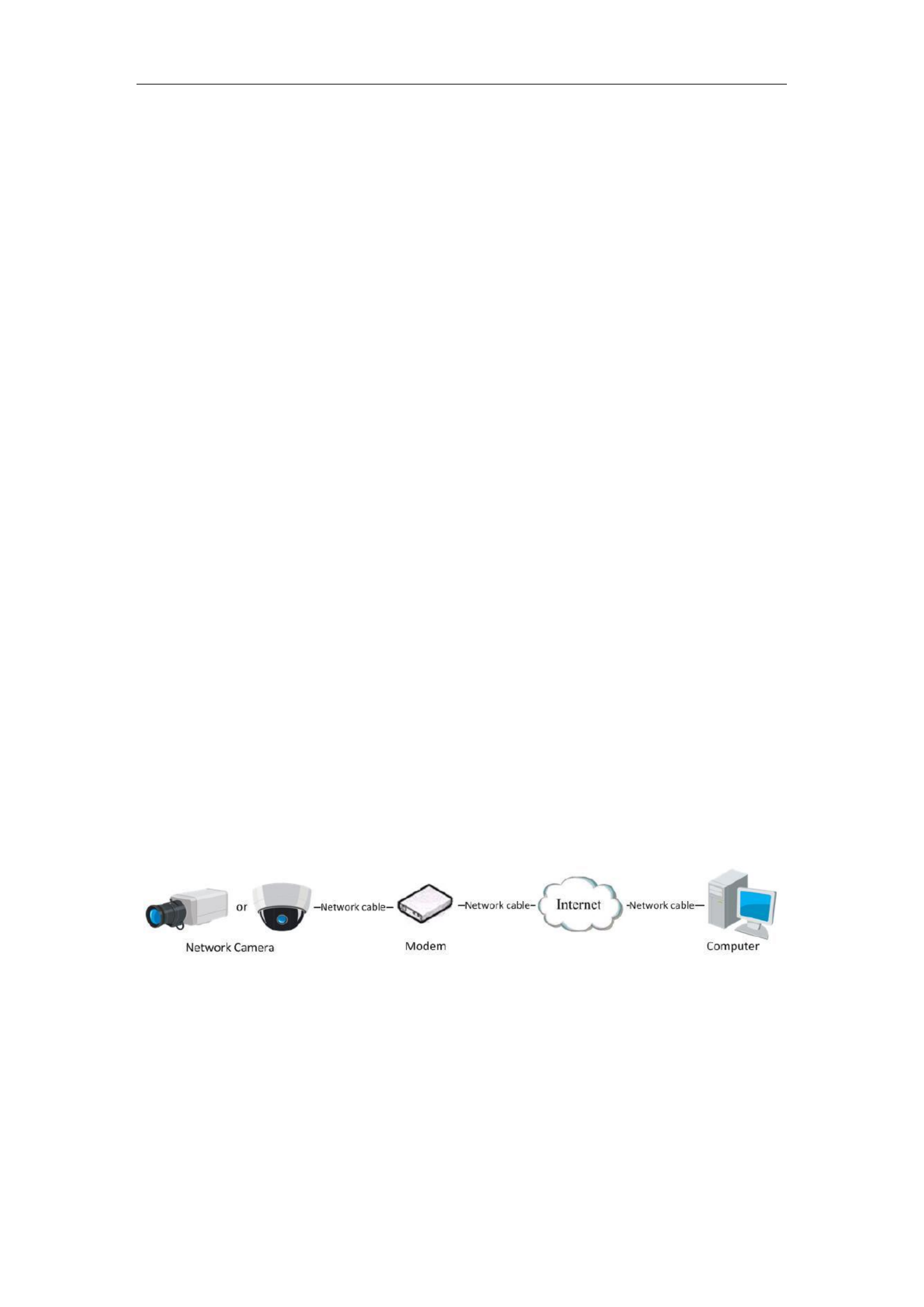
Connecting the network camera via a modem
Purpose:
This camera supports the PPPoE auto dial-up function. The camera gets a public IP
address by ADSL dial-up after the camera is connected to a modem. You need to
configure the PPPoE parameters of the network camera. Refer to Section 6.3.3
Configuring PPPoE Settings for detailed configuration.
Figure 2-6 Accessing the Camera with Dynamic IP
Note: The obtained IP address is dynamically assigned via PPPoE, so the IP address
always changes after rebooting the camera. To solve the inconvenience of the
dynamic IP, you need to get a domain name from the DDNS provider (E.g.
DynDns.com). Please follow the steps below for normal domain name resolution and
private domain name resolution to solve the problem.

User Manual of Network Camera
14
Normal Domain Name Resolution
Figure 2-7 Normal Domain Name Resolution
Steps:
1. Apply a domain name from a domain name provider.
2. Configure the DDNS settings in the DDNS Settings interface of the network
camera. Refer to for detailed Section 6.3.4 Configuring DDNS Settings
configuration.
3. Visit the camera via the applied domain name.
Private Domain Name Resolution
Figure 2-8 Private Domain Name Resolution
Steps:
1. Install and run the IP Server software in a computer with a static IP.
2. Access the network camera through the LAN with web browser or the client a
software.
3. Enable DDNS and select IP Server as the protocol type. Refer to Section 6.3.4
Configuring DDNS Settings for detailed configuration.

User Manual of Network Camera
15
Chapter 3 Access to the Network
Camera
3.1 Accessing by Web Browsers
Steps:
1. Open the web browser.
2. Input the IP address of the network camera in the address bar, e.g., 192.0.0.64 and
press the key to enter the login interfa . Enter ce
3. Input the user name and password and click . Login
Figure 3-1 Login Interface
Notes :
The default user name is , and the default password is . admin 12345
This product has default user name and password credentials for first time access.
You must change these default credentials to protect against unauthorized access
to the product. For details, please refer to . Section 12.1 Managing User Accounts
4. Install the plug-in before viewing the live video and operating the camera. Please
follow the installation prompts to install the plug- . in

User Manual of Network Camera
16
Figure 3-2 Download and Install Plug- in
Figure 3-3 Install Plug-in (1)
Figure 3-4 Install Plug-in (2)
Note: You may have to close the web browser to install the plug-in. Please reopen the
web browser and log in again after installing the plug-in.

User Manual of Network Camera
17
3.2 Accessing by Client Software
The product CD contains the iVMS-4200 client software. You can view the live video
and manage the camera with the software.
Follow the installation prompts to install the software. The control panel and live view
interface of iVMS-4200 client software are shown as bellow.
Figure 3-5 iVMS-4200 Control Panel

User Manual of Network Camera
18
Figure 3-6 iVMS-4200 Main View
Note: For detailed information about the software, please refer to the user manual of
the iVMS-4200.
User Manual of Network Camera
19
Chapter 4 -Fi Settings Wi
Purpose:
By connecting to the wireless network, you don’t need to use cable of any kind for
network connection, which is very convenient for the actual surveillance application.
Note: This chapter is only applicable for the cameras with the built-in -Fi module.Wi
4.1 Configuring Wi-Fi Connection in Manage and
Ad-hoc Modes
Before you start:
A wireless network must be configured.
Wireless Connection in Manage Mode
Steps:
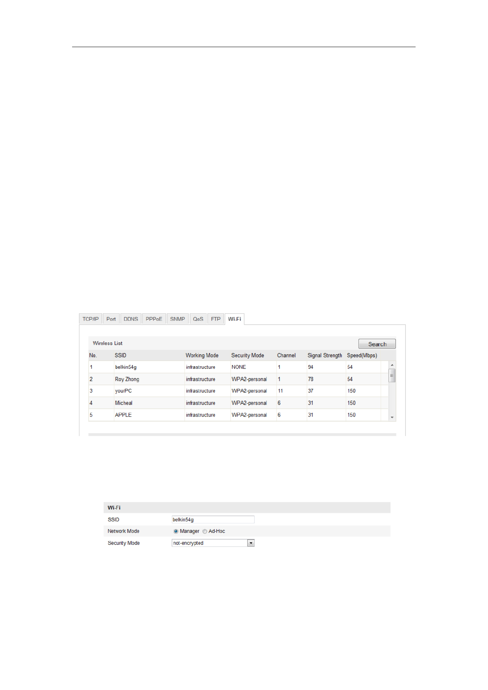
1. Enter the Wi-Fi configuration interface.
Configuration> Advanced Configuration> Network> Wi- Fi
Figure 4-1 Wireless Network List
2. Click Search to search the online wireless connections.
3. Click to choose a wireless connection on the list.
Figure 4-2 -Fi Setting- Manage Mode Wi

User Manual of Network Camera
20
4. Check the checkbox to select the and the Network mode as Manage, Security
mode of the network is automatically shown when you select the wireless
network, please don’t change it manually.
Note: These parameters are exactly identical with those of the router.
5. Enter the key to connect the wireless network. The key should be that of the
wireless network connection you set on the router.
Wireless Connection in Ad-hoc Mode
If you choose the Ad-hoc mode, you don’t need to connect the wireless camera via a
router. The scenario is the same as you connect the camera and the PC directly with a
network cable.
Steps:
1. Choose Ad-hoc mode.
Figure 4-3 -Fi Setting- Wi Ad-hoc
2. Customize a SSID for the camera.
3. Choose the Security Mode of the wireless connection.
Figure 4-4 Security Mode- Ad-hoc Mode
4. Enable the wireless connection function for your PC.
5. On the PC side, search the network and you can see the SSID of the camera
listed.

User Manual of Network Camera
21
Figure 4-5 -hoc Connection Point Ad
6. Choose the SSID and connect.
Security Mode Description:
Figure 4-6 Security Mode
You can choose the Security Mode as not-encrypted, WEP, WPA-personal,
WPA-enterprise, WPA2-personal, and WPA2-enterprise.
WEP mode:
Figure 4-7 WEP Mode
Authentication - Select Open or Shared Key System Authentication, depending on

User Manual of Network Camera
22
the method used by your access point. Not all access points have this option, in
which case they probably use Open System, which is sometimes known as SSID
Authentication.
Key length - This sets the length of the key used for the wireless encryption, 64 or
128 bit. The encryption key length can sometimes be shown as 40/64 and
104/128.
Key type - The key types available depend on the access point being used. The
following options are available:
HEX - Allows you to manually enter the hex key.
ASCII - In this method the string must be exactly 5 characters for 64-bit WEP
and 13 characters for 128-bit WEP.
WPA-personal and WPA2-personal Mode:
Enter the required Pre-shared Key for the access point, which can be a hexadecimal
number or a passphrase.
Figure 4-8 Security Mode- WPA-personal
WPA- enterprise and WPA2-enterprise Mode:
Choose the type of client/server authentication being used by the access point;
EAP-TLS or EAP-PEAP.
EAP-TLS

User Manual of Network Camera
23
Figure 4-9 EAP-TLS
Identity - Enter the user ID to present to the network.
Private key password Enter the password for your user ID. –
EAPOL version - Select the version used (1 or 2) in your access point.
CA Certificates - Upload a CA certificate to present to the access point for
authentication.
EAP-PEAP:
User Name - Enter the user name to present to the network
Password - Enter the password of the network
PEAP Version - Select the PEAP version used at the access point.
Label - Select the label used by the access point.
EAPOL version - Select version (1 or 2) depending on the version used at the
access point
CA Certificates - Upload a CA certificate to present to the access point for
authentication
4.2 Easy Wi-Fi Connection with WPS function
Purpose:
The setting of the wireless network connection is never easy. To avoid the complex
setting of the wireless connection you can enable the WPS function.

User Manual of Network Camera
24
WPS (Wi-Fi Protected Setup) refers to the easy configuration of the encrypted
connection between the device and the wireless router. The WPS makes it easy to add
new devices to an existing network without entering long passphrases. There are two
modes of the WPS connection, the PBC mode and the PIN mode.
Note: If you enable the WPS function, you do not need to configure the parameters
such as the encryption type and you don’t need to know the key of the wireless
connection.
Steps:
Figure 4-10 -Fi Settings - WPS Wi
PBC Mode:
PBC refers to the Push-Button-Configuration, in which the user simply has to push a
button, either an actual or virtual one (as the button on the configuration
interface of the IE browser), on both the Access Point (and a registrar of the network)
and the new wireless client device.
1. Check the checkbox of to enable WPS.
2. Choose the connection mode as PBC.
Note: Support of this mode is mandatory for both the Access Points and the
connecting devices.
3. Check on the Wi-Fi router to see if there is a WPS button. If yes push the button
and you can see the indicator near the button start flashing, which means the WPS
function of the router is enabled. For detailed operation, please see the user guide of
the router.

User Manual of Network Camera
25
4. Push the WPS button to enable the function on the camera.
If there is not a WPS button on the camera, you can also click the virtual button to
enable the PBC function on the web interface.
5. Click button. Connect
When the PBC mode is both enabled in the router and the camera, the camera and the
wireless network is connected automatically.
PIN Mode:
The PIN mode requires a Personal Identification Number (PIN) to be read from either
a sticker or the display on the new wireless device. This PIN must then be entered to
connect the network, usually the Access Point of the network.
Steps:
1. Choose a wireless connection on the list and the SSID is shown.
Figure 4-11 -Fi Settings WPS PIN Mode Wi –
2. Choose Use route PIN code.
If the PIN code is generated from the router side, you should enter the PIN code you
get from the router side in the Router PIN code field.

User Manual of Network Camera
26
3. Click . Connect
Or
You can generate the PIN code on the camera side. And the expired time for the PIN
code is 120 seconds.
1. Click . Generate
2. Enter the code to the router, in the example, enter 48167581 to the router.
4.3 IP Property Settings for Wireless Network
Connection
The default IP address of wireless network interface controller is 192.168.1.64. When
you connect the wireless network you can change the default IP.
Steps:
1. Enter the TCP/IP configuration interface.
Configuration> Advanced Configuration> Network> TCP/IP
Or
Configuration> Basic Configuration> Network> TCP/IP
Figure 4-12 TCP/IP Settings
2. Select the NIC as wlan.
3. Customize the IPv4 address, the IPv4 Subnet Mask and the Default Gateway.
The setting procedure is the same with that of LAN.
If you want to be assigned the IP address you can check the checkbox to enable the
DHCP.

User Manual of Network Camera
27
Chapter 5 Live View
5.1 Live View Page
Purpose:
The live view page allows you to view the real-time video, capture images, realize
PTZ control, set/call presets and configure video parameters.
Log the network camera to enter the live view page, or you can click in Live View on
the menu bar of the main page to enter the live view page.
Descriptions of the live view page:
Figure 5-1 Live View Page
Camera Mode l:
It lists the camera model you are connecting to.
Online Help:
Click to get the online help, which will guide you through the basic operations for
each function.
Menu Bar:
Click each tab to enter Live View, Playback, Log and Configuration page
respectively.

User Manual of Network Camera
28
Display Control:
Click each tab to adjust the layout and the stream type of the live vi . And you can ew
click the drop-down to select the plug-in. For IE (internet explorer) user,
webcomponents and quick time are selectable. And for Non-IE user, webcomponents,
quick time, VLC or MJPEG is selectable if they are supported by the web browser.
Live View Window:
Display the live video.
Toolbar:
Operations on the live view page, e.g., live view, capture, record, audio on/off,
two-way audio, etc.
PTZ Control:
Panning, tilting and zooming actions of the camera and the light and wiper control.
(only available for cameras supporting PTZ function)
Preset/Patrol Settings :
Set/call/delete the presets or patrols for PTZ cameras.
5.2 Starting Live View
In the live view window as shown in Figure 5-2, click on the toolbar to start the
live view of the camera.
Figure 5-2 Live View Toolbar
Table 5-1 Descriptions of the Toolbar
Icon
Description
/
Start/Stop live view.
The window size is 4:3.
The window size is 16:9.
The origin widow size. al
Self-adaptive window size.
Live view with the main stream.
Live view with the sub stream.
Live view with the third stream.

User Manual of Network Camera
29
Click to select the third-party plug- . in
Manually capture the picture.
/
Manually start/stop recording.
/
Audio on and adjust volume /Mute.
/
Turn on/off microphone.
/
Turn on/off digital zoom function.
/
Turn on/off 3D positioning function.
Note: The third stream and 3D positioning require the support of camera.
5.3 Recording and Capturing Pictures Manually
In the live view interface, click on the toolbar to capture the live pictures or
click to record the live view. The saving paths of the captured pictures and clips
can be set on the page. To configure remote Configuration > Local Configuration
scheduled recording, please refer to . Section 7.2
Note: The captured image will be saved as JPEG file or BMP file your computer. in
5.4 Operating PTZ Control
Purpose:
In the live view interface, you use the PTZ control buttons to realize pan/tilt/zoom can
control of the camera.
Before you start:
To realize PTZ control, the camera connected to the network must support the PTZ
function or a pan/tilt unit has been installed to the camera. Please properly set the PTZ
parameters on RS-485 settings page referring to Section 10.8 .RS-485 Settings
5.4.1 PTZ Control Panel
On the live view page, click to show the PTZ control panel click to or
hide . it

User Manual of Network Camera
30
Click the direction buttons to control the pan/tilt movements.
Figure 5-3 PTZ Control Panel
Click the zoom/iris/focus buttons to realize lens control.
Notes:
There are 8 direction arrows ( , , , , , , , ) in the live view window
when you click and drag the mouse in the relative positions.
For the cameras which support lens movements only, the direction buttons are
invalid.
Table 5-2 Descriptions of PTZ Control Panel
Icon
Description
Zoom in/out
Focus near/far
Iris / + -
Light on/off
Wiper on/off
Auxiliary focus
Initialize lens
Adjust speed of pan/tilt movements
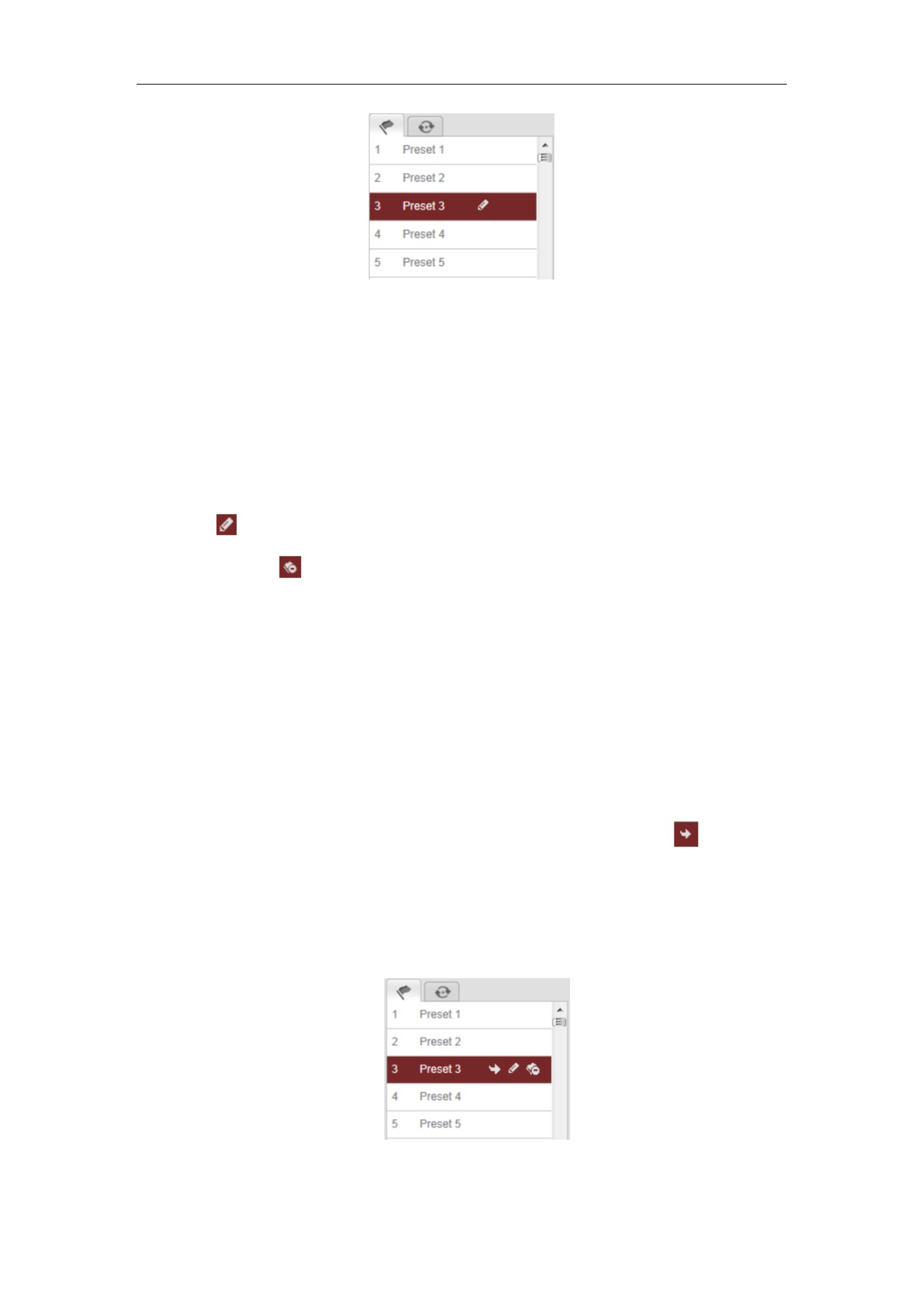
5.4.2 Setting / Calling a Preset
Setting a Preset:
1. In the PTZ control panel, select a preset number from the preset list.
User Manual of Network Camera
31
Figure 5-4 Setting a Preset
2. Use the PTZ control buttons to move the lens the desired position. to
• Pan the camera to the right or left.
• Tilt the camera up or down.
• Zoom in or out.
• Refocus the lens.
3. Click to finish the setting of the current preset.
4. You can click to delete the preset.
Note: You can configure up to 256 presets.
Calling a Preset:
This feature enables the camera to point to a specified preset scene manually or when
an event takes place.
For the defined preset, you can call it at any time to the desired preset scene.
In the PTZ control panel, select a defined preset from the list and click to call the
preset.
Or you can place the mouse on the presets interface, and call the preset by typing the
preset No. to call the corresponding presets.
Figure 5-5 Calling a Preset

User Manual of Network Camera
32
5.4.3 Setting / Calling a Patrol
Note:
No less than 2 presets have to be configured before you set a patrol.
Steps:
1. C k to enter the patrol configuration interface. lic
2. Select a path No., and click to add the configured presets.
3. Select the preset, and input the patrol duration and patrol speed.
4. Click OK to save the first preset.
5. Follow the steps above to add the other presets.
Figure 5-6 Add Patrol Path
6. Click to save a patrol.
7. Click to start the patrol, and click to stop it.
8. (Optional) Click to delete a patrol.
User Manual of Network Camera
33
Chapter 6 Network Camera
Configuration
6.1 Configuring Local Parameters
Note: The local configuration refers to the parameters of the live view, record files
and captured pictures. The record files and captured pictures are the ones you record
and captured using the web browser and thus the saving paths of them are on the PC
running the browser.
Steps:
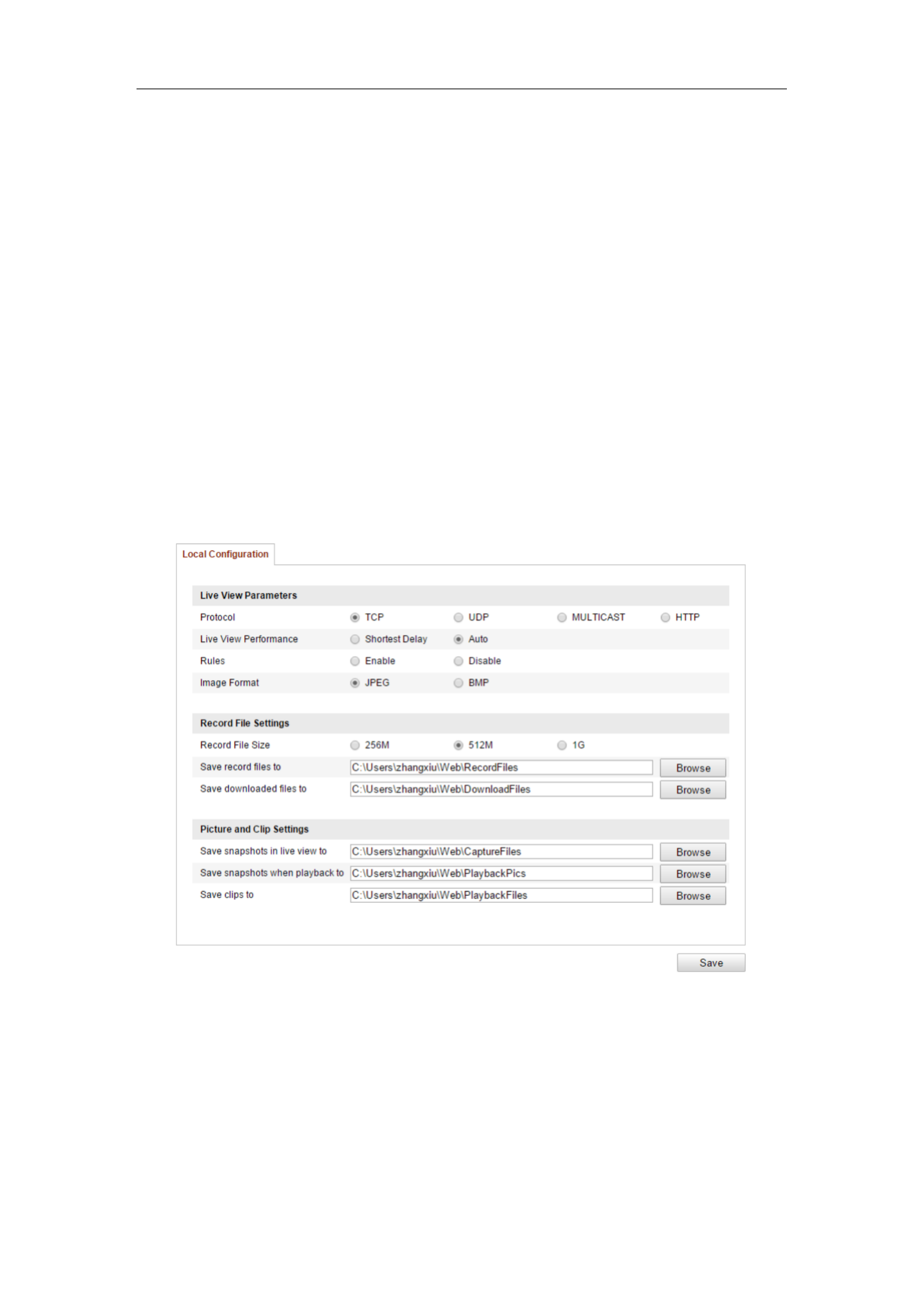
1. Enter the Local Configuration interface:
Configuration > Local Configuration
Figure 6-1 Local Configuration Interface
2. Configure the following settings:
Live View Parameters: Set the protocol type and live view performance.
Protocol Type: TCP, UDP, MULTICAST and HTTP are selectable.
TCP: Ensures complete delivery of streaming data and better video quality,
yet the real-time transmission will be affected.

User Manual of Network Camera
34
UDP: Provides real-time audio and video streams.
HTTP: Allows the same quality as of TCP without setting specific ports for
streaming under some network environments.
MULTICAST: It’s recommended to select MCAST type when using the
Multicast function. For detailed information about Multicast, refer to Section
6.3.1 Configuring TCP/IP Settings.
Live View Performance: Set the live view performance to Shortest Delay or
Auto.
Rules: It refers to the rules on your local browser, select enable or disable to
display or not display the colored marks when the motion detection, face
detection, or intrusion detection is triggered. E.g.: enabled as the rules are, and
the face detection is enabled as well, when a face is detected, it will be marked
with a green rectangle on the live view.
Image Format: Choose the image format for picture capture.
Record File Settings: Set the saving path of the recorded video files. Valid for the
record files you recorded with the web browser.
Record File Size: Select the packed size of the manually recorded and
downloaded video files to 256M, 512M or 1G. After the selection, the
maximum record file size is the value you selected.
Save record files to: Set the saving path for the manually recorded video files.
Save downloaded files to: Set the saving path for the downloaded video files
in playback mode.
Picture and Clip Settings: Set the saving paths of the captured pictures and
clipped video files. Valid for the pictures you captured with the web browser.
Save snapshots in live view to: Set the saving path of the manually captured
pictures in live view mode.
Save snapshots when playback to: Set the saving path of the captured
pictures in playback mode.
Save clips to: Set the saving path of the clipped video files in playback mode.
Note: You can click to change the directory for saving the clips and pictures. Browse

User Manual of Network Camera
35
3. Click to save the settings. Save
6.2 Configuring Time Settings
Purpose:
You can follow the instructions in this section to configure the time synchronization
and DST settings.
Steps:
1. Enter the Time Settings interface:
Configuration > Basic Configuration > System > Time Settings
Or Configuration > Advanced Configuration > System > Time Settings
Figure 6-2 Time Settings
Select the Time Zone.
Select the Time Zone of your location from the drop-down menu.
Synchronizing Time by NTP Server.
(1) Check the checkbox to enable the function. NTP
(2) Configure the following settings:
Server Address: IP address of NTP server.
NTP Port: Port of NTP server.
Interval: The time interval between the two synchronizing actions with NTP
server.

User Manual of Network Camera
36
Figure 6-3 Time Sync by NTP Server
Note: If the camera is connected to a public network, you should use a NTP server
that has a time synchronization function, such as the server at the National Time
Center (IP Address: 210.72.145.44). If the camera is set in a customized network,
NTP software can be used to establish a NTP server for time synchronization.
Synchronizing Time Synchronization Manually
Enable the Manual Time Sync function and then click to set the system time
from the pop-up calendar.
Note: You can also check the Sync with computer time checkbox to synchronize the
time of the camera with that of your computer.
Figure 6-4 Time Sync Manually
Click the tab page to enable the DST function and Set the date of the DST DST
period.
Figure 6-5 DST Settings
2. Click to save the settings. Save

User Manual of Network Camera
37
6.3 Configuring Network Settings
6.3.1 Configuring TCP/IP Settings
Purpose:
TCP/IP settings must be properly configured before you operate the camera over
network. The camera supports both the IPv4 and IPv6. Both versions may be
configured simultaneously without conflicting to each other, and at least one IP
version should be configured.
Steps:
1. Enter TCP/IP Settings interface:
Configuration > Basic Configuration > Network > TCP/IP
Or Configuration > Advanced Configuration > Network > TCP/IP
Figure 6-6 TCP/IP Settings
2. Configure the basic network settings, including the NIC Type, IPv4 or IPv6
Address, IPv4 or IPv6 Subnet Mask, IPv4 or IPv6 Default Gateway, MTU settings

User Manual of Network Camera
38
and Multicast Address.
3. (Optional) Check the checkbox of , and then the Enable Multicast Discovery
online network camera can be automatically detected by client software via
private multicast protocol in the LAN.
4. Click to save the above settings Save .
Notes :
The valid value range of MTU is 1280 ~ 1500.
The Multicast sends a stream to the multicast group address and allows multiple
clients to acquire the stream at the same time by requesting a copy from the
multicast group address. Before utilizing this function, you have to enable the
Multicast function of your router.
A reboot is required for the settings to take effect.
6.3.2 Configuring Port Settings
Purpose:
You can set the port No. of the camera, e.g. HTTP port, RTSP port and HTTPS port.
Steps:
1. Enter the Port Settings interface:
Configuration > Basic Configuration > Network > Port
Or Configuration > Advanced Configuration > Network > Port
Figure 6-7 Port Settings
2. Set the HTTP port, RTSP port, HTTPS port and server port of the camera.
HTTP Port: The default port number is 80, and can be changed to any port No. it
which is not occupied.

User Manual of Network Camera
39
RTSP Port: The default port number is 554 and it can be changed to any port No.
ranges from 1024 to 65535.
HTTPS Port: The default port number is 443, and can be changed to any port it
No. which is not occupied.
Server Port: The default server port number is 8000, and it can be changed to
any port No. ranges from 2000 to 65535.
3. Click to save the settings. Save
Note: A reboot is required for the settings to take effect.
6.3.3 Configuring PPPoE Settings
Steps:
1. Enter the PPPoE Settings interface:
Configuration >Advanced Configuration > Network > PPPoE
Figure 6-8 PPPoE Settings
2. Check the checkbox to enable this feature. Enable PPPoE
3. Enter , , and password for PPPoE access. User Name Password Confirm
Note: The User Name and Password should be assigned by your ISP.
4. Click to save and exit the interface. Save
Note: A reboot is required for the settings to take effect.
6.3.4 Configuring DDNS Settings
Purpose:
If your camera is set to use PPPoE as its default network connection, you can use the
Dynamic DNS (DDNS) for network access.
User Manual of Network Camera
40
Before you start:
Registration on the DDNS server is required before configuring the DDNS settings of
the camera.
Steps:
1. Enter the DDNS Settings interface:
Configuration > Advanced Configuration > Network > DDNS
Figure 6-9 DDNS Settings
2. Check the checkbox to enable this feature. Enable DDNS
3. Select . Four DDNS types are selectable: HiDDNS, IPServer, -IP, DDNS Type NO
and DynDNS.
DynDNS:
Steps:
(1) Enter of DynDNS (e.g. members.dyndns.org). Server Address
(2) In the text field, enter the domain name obtained from the DynDNS Domain
website.
(3) Enter the of DynDNS server. Port
(4) Enter the and registered on the DynDNS website. User Name Password
(5) Click to save the settings. Save

User Manual of Network Camera
41
Figure 6-10 DynDNS Settings
IP Server:
Steps:
(1) Enter the Server Address of the IP Server.
(2) Click to save the settings. Save
Note: For the IP Server, you have to apply a static IP, subnet mask, gateway and
preferred DNS from the ISP. The should be entered with the Server Address
static IP address of the computer that runs the IP Server software.
Figure 6-11 IPServer Settings
Note: For the US and Canada area, you can enter 173.200.91.74 as the server
address.
NO- : IP
Steps:
(1) Choose the DDNS Type as - . NO IP

User Manual of Network Camera
42
Figure 6-12 -IP Settings NO
(2) Enter the Server Address as www.noip.com
(3) Enter the Domain name you registered.
(4) Enter the Port number, if needed.
(5) Enter the User Name and Password.
(6) Click and then you can view the camera with the domain name. Save
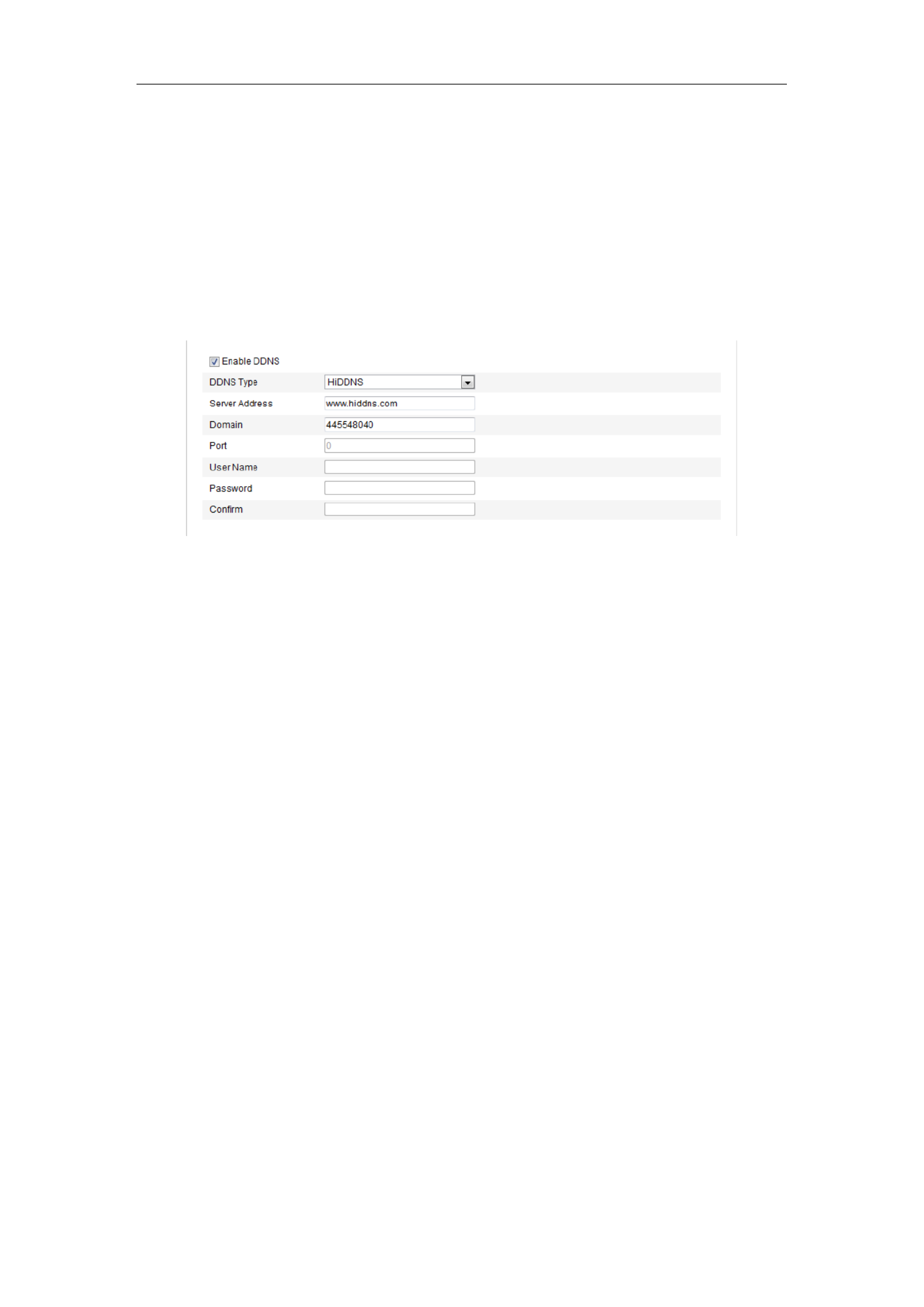
HiDDNS
Steps:
(1) Choose the DDNS Type as HiDDNS.
Figure 6-13 HiDDNS Settings
(2) Enter the Server Address www.hiddns.com
(3) Enter the Domain name of the camera. The domain is the same with the
device alias in the HiDDNS server.
(4) Click to save the new settings. Save
Note: A reboot is required for the settings to take effect.

User Manual of Network Camera
43
6.3.5 Configuring SNMP Settings
Purpose:
You can set the SNMP function to get camera status, parameters and alarm related
information and manage the camera remotely when it is connected to the network.
Before you start:
Before setting the SNMP, please download the SNMP software and manage to
receive the camera information via SNMP port. By setting the Trap Address, the
camera can send the alarm event and exception messages to the surveillance center.
Note: The SNMP version you select should be the same as that of the SNMP software.
And you also need to use the different version according to the security level you
required. SNMP v1 provides no security and SNMP v2 requires password for access.
And SNMP v3 provides encryption and if you use the third version, HTTPS protocol
must be enabled.
Steps:
1. Enter the SNMP Settings interface:
Configuration > Advanced Configuration > Network > SNMP

User Manual of Network Camera
44
Figure 6-14 SNMP Settings
2. Check the corresponding version checkbox ( ,
, ) to enable the featur e.
3. Configure the SNMP settings.
Note: The settings of the SNMP software should be the same as the settings you
configure here.
4. Click to save and finish the settings. Save
Note: A reboot is required for the settings to take effect.
6.3.6 Configuring 802.1X Settings
Purpose:
User Manual of Network Camera
45
The IEEE 802.1X standard is supported by the network cameras, and when the feature
is enabled, the camera data is secured and user authentication is needed when
connecting the camera to the network protected by the IEEE 802.1X.
Before you star t:
The authentication server must be configured. Please apply and register a user name
and password for 802.1X in the server.
Steps:
1. Enter the 802.1X Settings interface:
Configuration > Advanced Configuration > Network > 802.1X
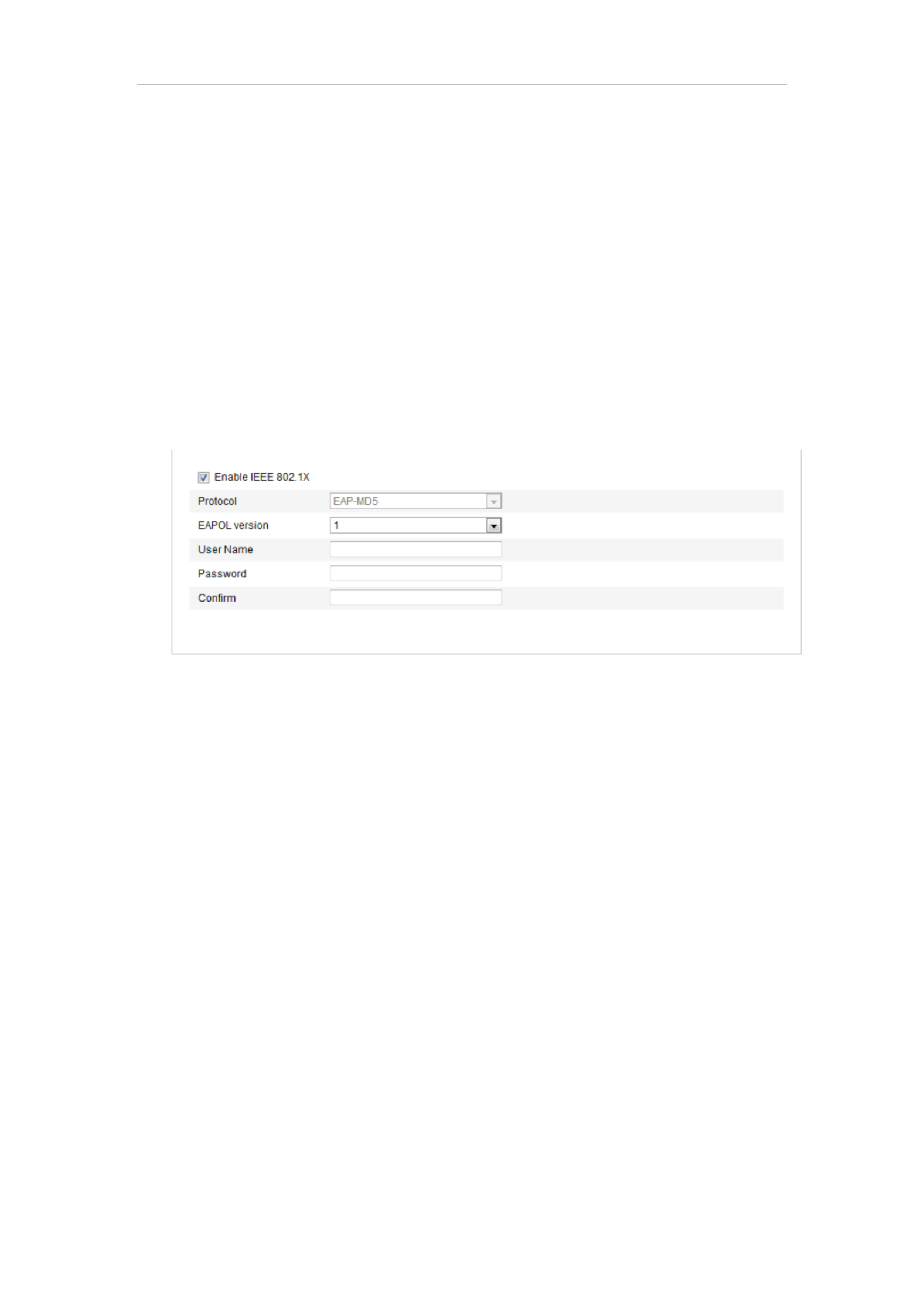
Figure 6-15 802.1X Settings
2. Check the checkbox to enable the feature. Enable IEEE 802.1X
3. Configure the 802.1X settings, including EAPOL version, user name and
password.
Note: The EAPOL version must be identical with that of the router or the switch.
4. Enter the user name and password to access the server.
5. Click to finish the settings. Save
Note: A reboot is required for the settings to take effect.
6.3.7 Configuring QoS Settings
Purpose:
QoS (Quality of Service) can help solve the network delay and network congestion by
configuring the priority of data sending.
Steps:

User Manual of Network Camera
46
1. Enter the QoS Settings interface:
Configuration >Advanced Configuration > Network > QoS
Figure 6-16 QoS Settings
2. Configure the QoS settings, including video / audio DSCP, event / alarm DSCP
and Management DSCP.
The valid value range of the DSCP is 0-63. The bigger the DSCP value is, the
higher the priority is.
Note: DSCP refers to the Differentiated Service Code Point; and the DSCP value
is used in the IP header to indicate the priority of the data.
3. Click to save the settings. Save
Note: A reboot is required for the settings to take effect.
6.3.8 Configuring UPnP™ Settings
Universal Plug and Play (UPnP™) is a networking architecture that provides
compatibility among networking equipment, software and other hardware devices.
The UPnP protocol allows devices to connect seamlessly and to simplify the
implementation of networks in the home and corporate environments.
With the function enabled, you don’t need to configure the port mapping for each port,
and the camera is connected to the Wide Area Network via the router.
Steps:
1. Enter the UPnP™ settings interface.
Configuration >Advanced Configuration > Network > UPnP
2. Check the checkbox to enable the UPnP™ function.
The name of the device when detected online can be edited.

User Manual of Network Camera
47
Figure 6-17 UPnP Settings
6.3.9 Configuring Wireless Dial Settings
Purpose:
Data stream of audio, video and image can be transferred via 3G / 4G wireless
network.
Note: The wireless dial function requires the support of the camera.
1. Click the Wireless Dial tab to enter the Wireless Dial configuration interfac e.
2. Check the checkbox of to enable the wireless dial settings. Enable
3. Configure the dial parameters.
1) Select the dial mode from the drop-down list. Auto and Manual are selectable.
If Auto is selected, you can set the arming schedule for dialing; If Manual is
selected, you can set the offline time and manual dialing parameters.
2) Set the access number, user name, password, APN, MTU and verification
protocol. You can also leave these parameters blank, and the device will
adopt the default settings for dialing after other parameters are configured.
3) Select the network mode from the drop-down list. Auto, 3G and 4G are
selectable. If Auto is selected, the network selection priority comes as: 4G >
3G > Wired Network.
4) Input the offline time if Manual is selected as the dial mode.
5) Input the UIM Number (Mobile Phone Number).
6) Click the button to set the arming schedule if Auto is selected as the dial Edit
mode.
7) Click to save the settings. Save

User Manual of Network Camera
48
Figure 6-18 Dial Parameters
4. View the dial status.
1) Click the button to view the dial status including real-time mode, Refresh
UIM status, signal strength, etc.
2) If Manual is selected as the dial mode, you can also manually connect /
disconnect the wireless network.
Figure 6-19 Dial Status
5. Set the white list.

User Manual of Network Camera
49
1) Check the checkbox of . Enable SMS Alarm
The mobile phone number on the white list can receive the alarm message
from the device and reboot the device via SMS.
Note: Up to 8 mobile phone numbers can be added on the white list.
Figure 6-20 White List Settings
2) Select the item on the white list, and click the button to enter the SMS Edit
Alarm Settings interface.
Figure 6-21 SMS Alarm Settings
3) Input the mobile phone number for the white list, check the checkbox of
Reboot via SMS, select the alarm for SMS push, and click OK.
Note: To reboot the device via SMS, send the message "reboot" to the device,
and the device will reply a message "reboot success" after rebooting
succeeded.
4) (Optional) You can click to send a message to the mobile Send Test SMS
phone for test.

User Manual of Network Camera
50
5) Click to save the settings. Save
6.3.10 Email Sending Triggered by Ala rm
Purpose:
The system can be configured to send an Email notification to all designated receivers
if an alarm event is detected, e.g., motion detection event, video loss, video tampering,
etc.
Before you start:
Please configure the DNS Server settings under Basic Configuration > Network >
TCP/IP Advanced Configuration > Network > TCP/IPor before using the Email
function.
Steps:
1. Enter the TCP/IP Settings (Configuration > Basic Configuration > Network >
TCP/IP Configuration > Advanced Configuration > Network > TCP/IP) or to
set the IPv4 Address, IPv4 Subnet Mask, IPv4 Default Gateway and the Preferred
DNS Server.
Note: Please refer to for detailed Configuring TCP/IP SettingsSection 6.3.1
information.
2. Enter the Email Settings interface:
Configuration > Advanced Configuration > Network > Email

User Manual of Network Camera
51
Figure 6-22 Email Settings
3. Configure the following settings:
Sender: The name of the email sender.
Sender’s Address: The email address of the sender.
SMTP Server: The SMTP Server IP address or host name (e.g.,
smtp.263xmail.com).
SMTP Port: The SMTP port. The default TCP/IP port for SMTP is 25 (not
secured). And the SSL SMTP port is 465.
Enable SSL: Check the checkbox to enable SSL if it is required by the SMTP
server.
Attached Image: Check the checkbox of Attached Image if you want to send
emails with attached alarm images.
Interval: The interval refers to the time between two actions of sending attached
pictures.
Authentication (optional): If your email server requires authentication, check
this checkbox to use authentication to log in to this server and enter the login user

User Manual of Network Camera
52
Name and password.
Choose Receiver: Select the receiver to which the email is sent. Up to 2 receivers
can be configured.
Receiver: The name of the user to be notified.
Receiver’s Address: The email address of user to be notified.
4. Click to save the settings. Save
6.3.11 Configuring NAT (Network Address Translation) Settings
Purpose:
1. Enter the NAT settings interface.
Configuration >Advanced Configuration > Network > NAT
2. Choose the port mapping mode.
To port mapping with the default port numbers:
Choose Port Mapping Mode as Auto .
To port mapping with the customized port numbers:
Choose Port Mapping Mode as . Manual
And for manual port mapping, you can customize the value of the port number by
yourself.
Figure 6-23 Configure NAT Settings
3. Click to save the settings. Save
6.3.12 Configuring FTP Settings
Purpose:

User Manual of Network Camera
53
You can configure the FTP server related information to enable the uploading of the
captured pictures to the FTP server. The captured pictures can be triggered by events
or a timing snapshot task.
Steps:
1. Enter the FTP Settings interface:
Configuration >Advanced Configuration > Network > FTP
Figure 6-24 FTP Settings
2. Configure the FTP settings; and the user name and password are required for
login the FTP server.
Directory Directory Structure: In the field, you can select the root directory,
parent directory and child directory. When the parent directory is selected, you
have the option to use the Device Name, Device Number or Device IP for the
name of the directory; and when the Child Directory is selected, you can use the
Camera Name or Camera No. as the name of the directory.
Upload type: To enable uploading the captured picture to the FTP server.
Anonymous Access to the FTP Server (in which case the user name and
password won’t be required.): AnonymousCheck the checkbox to enable the
anonymous access to the FTP server.
Note: The anonymous access function must be supported by the FTP server.
3. Click to save the settings. Save
Note: If you want to upload the captured pictures to FTP server, you have to
enable the continuous snapshot or event-triggered snapshot on page. Snapshot
For detailed information, please refer to the Section 6.6.7.
User Manual of Network Camera
54
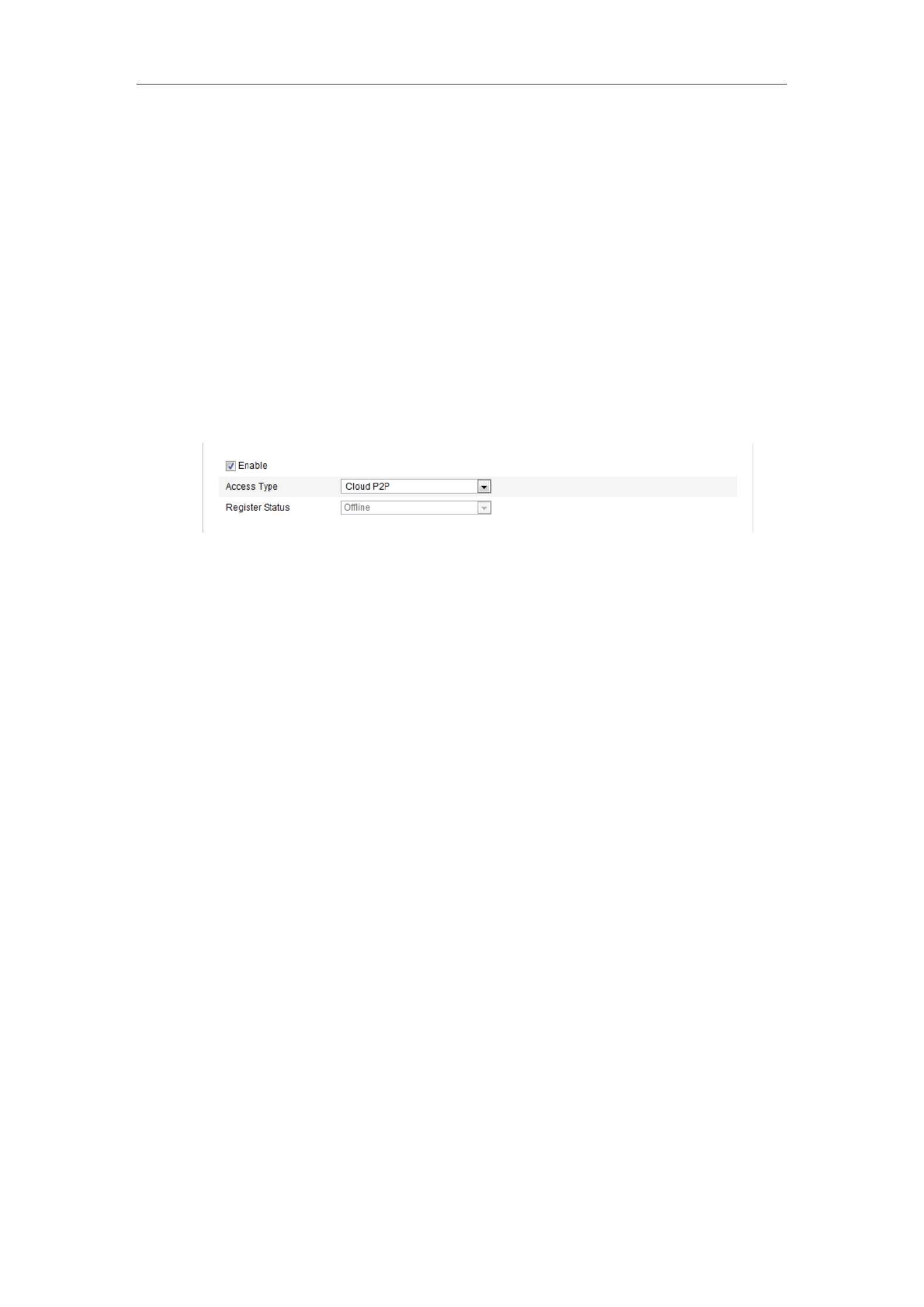
6.3.13 Platform Access
Platform access provides you an option to manage devices via Cloud P2P platform.
Note: Platform access function varies according to the camera model and it requires
for the support of the camera.
Check the checkbox of to enable the Cloud P2P, and you are able to manage Enable
the device via Cloud P2P website, or Cloud P2P client, which is a mobile phone app.
For some users don t want to manage the devices via Cloud P2P, you can just simply ’
leave the checkbox unchecked.
Figure 6-25 Platform Access
6.3.14 HTTPS Settings
Purpose:
HTTPS provides authentication of the web site and associated web server that one is
communicating with, which protects against Man- -the-middle attacks. Perform the in
following steps to set the port number of https.
E.g.: If you set the port number as 443 and the IP address is 192.0.0.64, you may
access the device by inputting https://192.0.0.64:443 via the web browser.
Steps:
1. Enter the HTTPS settings interface.
Configuration > Advanced Configuration > Network > HTTPS
2. Create the self-signed certificate or authorized certificate.

User Manual of Network Camera
55
Figure 6-26 HTTPS Settings
Create the self-signed certificate
1) Click Create button to enter the creation interface.
Figure 6-27 Create Self-signed Certificate
2) Enter the country, host name/IP, validity and other information.
3) Click to save the settings. OK
Note: If you already had a certificate installed, the Create Self-signed
Certificate is grayed out.
Create the authorized certificate
1) Click Create button to create the certificate request.
2) Download the certificate request and submit it to the trusted certificate
User Manual of Network Camera
56
authority for signature.
3) After receiving the signed valid certificate, import the certificate to the device.
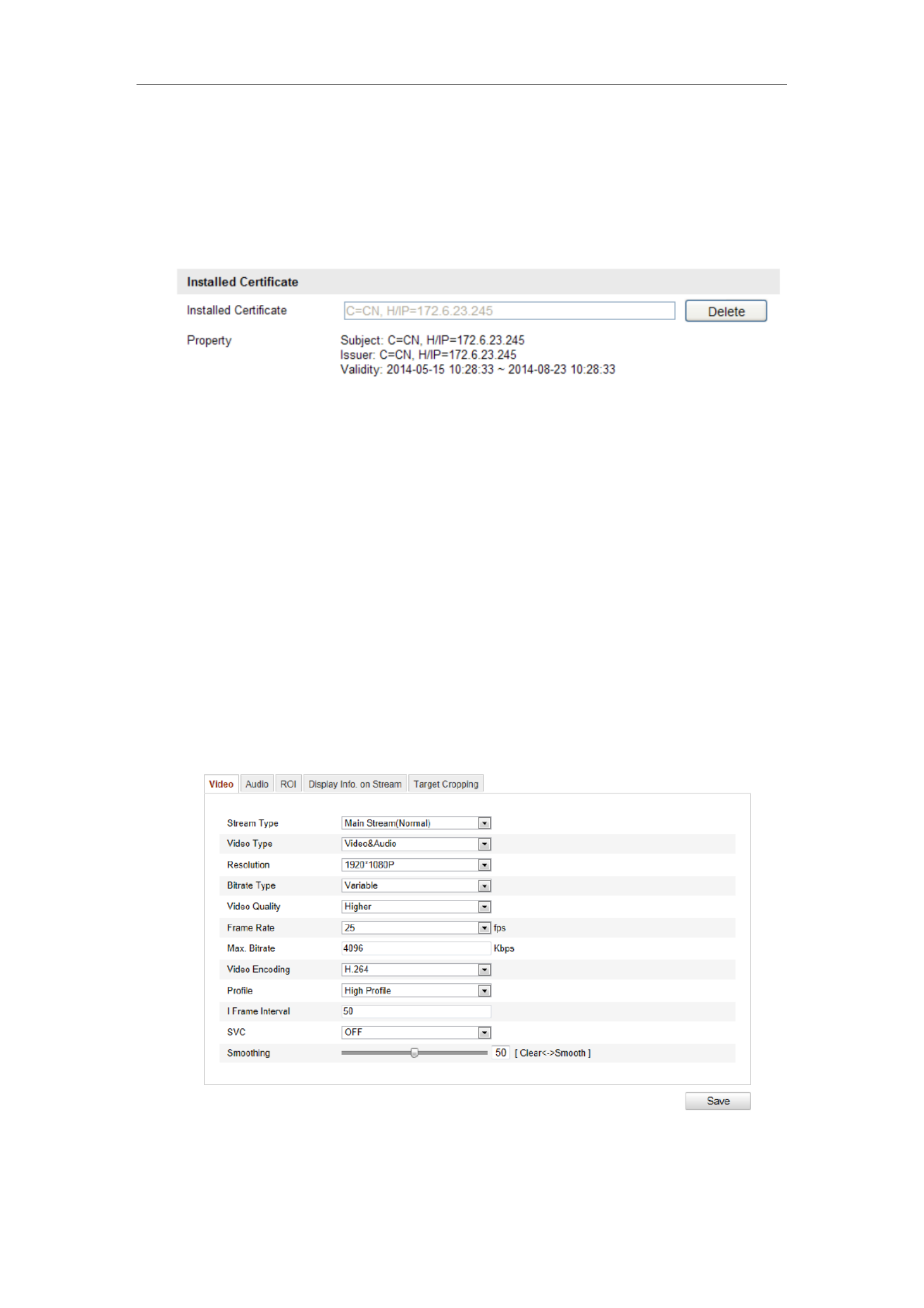
3. There will be the certificate information after you successfully create and install
the certificate.
Figure 6-28 Installed Certificate
4. Click the button to save the settings. Save
6.4 Configuring Video and Audio Settings
6.4.1 Configuring Video Settings
Steps:
1. Enter the Video Settings interface:
Configuration >Basic Configuration > Video / Audio > Video
Or Configuration > Advanced Configuration > Video / Audio > Video
Figure 6-29 Video Settings

User Manual of Network Camera
57
2. Select the Stream Type of the camera to main stream (normal), sub-stream or third
stream.
The main stream is usually for recording and live viewing with good bandwidth,
and the sub-stream and third stream can be used for live viewing when the
bandwidth is limited.
3. You can customize the following parameters for the selected main stream or
sub-stream:
Video Type:
Select the stream type to video stream, or video & audio composite stream. The
audio signal will be recorded only when the Video Type Video & Audio is .
Resolution:
Select the resolution of the video outpu t.
Bitrate Type:
Select the bitrate type to constant or variable.
Video Quality:
When bitrate type is selected as Variable, 6 levels of video quality are selectable.
Frame Rate:
Set the frame rate to 1/16~25 fps. The frame rate is to describe the frequency at
which the video stream is updated and it is measured by frames per second (fps).
A higher frame rate is advantageous when there is movement in the video stream,
as it maintains image quality throughout.
Max. Bitrate:
Set the max. bitrate to 32~16384 Kbps. The higher value corresponds to the higher
video quality, but the higher bandwidth is required.
Video Encoding:
If the Stream Type set to main stream, H.264 and MPEG4 are selectable, and if is
the stream type is set to sub stream or third stream, H.264, MJPEG, and MPEG4
are selectable.
Note: The supported video encoding may differ according to the different
platform.

User Manual of Network Camera
58
Profile:
Basic profile, Main Profile and High Profile for coding are selectable.
I Frame Interval:
Set the I-Frame interval to 1~400.
SVC:
Scalable Video Coding is an extension of the H.264/AVC standard. Select OFF /
ON to disable / enable the SVC function. Select Auto, and the device will
automatically extract frames from the original video when the network bandwidth
is insufficient.
Smoothing:
It refers to the smoothness of the stream. The higher value of the smoothing, the
better fluency of the stream, though, the video quality may not be so satisfied. The
lower value of the smoothing, the higher quality of the stream, though it may
appear not fluent.
4. Click to save the settings. Save
6.4.2 Configuring Audio Settings
Steps:
1. Enter the Audio Settings interface
Configuration > Basic Configuration > Video / Audio > Audio
Or Configuration > Advanced Configuration > Video / Audio > Audio
Figure 6-30 Audio Settings
2. Configure the following settings.
Note: Audio settings vary according to different camera models.

User Manual of Network Camera
59
Audio Encoding: G.722.1, G.711 ulaw, G.711alaw, G.726, MP2L2 and PCM are
selectable. For MP2L2, the sampling rate and audio stream bitrate are
configurable; for PCM, the sampling rate can be set.
Audio Input: MicIn and LineIn are selectable for the connected microphone and
pickup respectively.
Input Volume: 0-100
Environmental Noise Filter: Set it as OFF or ON. When you set the function on
the noise detected can be filtered.
Note: When the sampling rate is greater than 32kHz, the environmental noise
filter function is invalid.
3. Click to save the settings. Save
6.4.3 Configuring ROI Encoding
Purpose:
ROI (Region of Interest) encoding helps to discriminate the ROI and background
information in video compression, which means, the technology assigns more
encoding resource to the region of interest, thus to increase the quality of the ROI
whereas the background information is less focused.
Note: ROI function varies according to different camera models.

User Manual of Network Camera
60
Figure 6-31 Region of Interest Settings
Configuring Fixed Region for ROI:
Steps:
1. Enter the ROI settings interface:
Configuration> Advanced Configuration> Video/Audio> ROI
2. Check the checkbox of under Fixed Region item. Enable
3. Select the stream type for ROI encoding.
4. Select the region from the drop-down list for ROI settings. There are four fixed
regions selectable.
5. Click the Draw Area button, and then click-and-drag the mouse to draw the
region of interest on the live video.

User Manual of Network Camera
61
6. Select the ROI level to set the image quality enhancing level. The larger the value
is, the better the image quality is.
7. Input the region name for ROI as desired.
8. Click to save the settings. Save
Configuring Dynamic Region for ROI:
1. Enter the ROI settings interface:
Configuration> Advanced Configuration> Video/Audio> ROI
2. Check the checkbox of Enable Face Tracking, and then the captured face picture
is set as region of interest.
Note: To enable face tracking function, the face detection function should be
supported and enabled.
3. Check the checkbox of Enable License Plate Tracking, and then the captured
license plate picture is set as region of interest.
Note: To enable license plate tracking function, the vehicle detection function
should be supported and enabled.
4. Respectively set the ROI level. The larger the value is, the better the image
quality is.
5. Select the stream type for ROI encoding.
6. Click to save the settings. Save
6.4.4 Display Information on Stream
Check the checkbox of , and the information of the objects (e.g. Enable Dual-VCA
human, vehicle, etc.) will be marked in the video stream. And then you can set rules
on the connected rear-end device to detect the events including line crossing, intrusion,
etc.

User Manual of Network Camera
62
Figure 6-32 Display Info. on Stream
6.4.5 Configuring Target Cropping
Purpose:
You can specify a target area on the live video, and then can be displayed via the it
third stream in some certain resolution, thus providing more details of the target area
if needed.
Note: Target cropping function varies according to different camera models.
Steps:
1. Enter the Target Cropping settings interface:
Configuration> Advanced Configuration> Video/Audio> Target Cropping.
2. Check the checkbox of Enable Target Cropping to enable the function.
3. Set Third Stream as the stream type.
4. Select the cropping resolution for the video display of target area. A red rectangle
is displayed on the live video to mark the target area, and you can click-and-drag
the rectangle to locate the target area as desired.
5. Click to save the settings. You can go to the Live View page and click the Save
Third Stream tab to view the video of the target area.

User Manual of Network Camera
63
Figure 6-33 Target Cropping
6.5 Configuring Image Parameters
6.5.1 Configuring Display Settings
Purpose:
You can set the image quality of the camera, including brightness, contrast, saturation,
hue, sharpness, etc.
Note: The display parameters vary according to the different camera model. Please
refer to the actual interface for details.
Steps:
1. Enter the Display Settings interface:
Configuration > Basic Configuration> Image> Display Settings
Or Configuration > Advanced Configuration> Image> Display Settings
2. Set the image parameters of the camera.
Note: In order to guarantee the image quality in the different illumination, it provides
two sets of parameters for user to configure.
Day/Night Auto-switch

User Manual of Network Camera
64
Figure 6-34 Display Settings of Day/night Auto-switch
Image Adjustment
Brightness describes bright of the image, which ranges from 1~100, and the default
value is 50.
Contrast describes the contrast of the image, which ranges from 1~100, and the
default value is 50.
Saturation describes the colorfulness of the image color, which ranges from 1~100,
and the default value is 50.
Sharpness describes the edge contrast of the image, which ranges from 1~100, and
the default value is 50.
Exposure Settings
If the camera is equipped with the fixed lens, only is selectable, and the iris Manual
mode is not configurable.
If Auto is selected, you can set the auto iris level from 0~ 100.
For the camera supports lens, if P-Iris lens is adopted, then the P-Iris lens type P-Iris
is selectable, e.g.: Tamron 2.8-8mm F1.2 M13VP288- ), or if DC lens is adopted, ( IR
then manual and auto are selectable.
The exposure time refers to the electronic shutter time, which ranges from 1 ~

User Manual of Network Camera
65
1/100,000s. Adjust it according to the actual luminance condition.
Focus Settings
For the camera supports electronic lens, you can set the focus mode as Auto, Manual
or Semi-auto. If auto is selected, the focus is adjusted automatically according to the
actual monitoring scenario; if manual is selected, you can control the lens by adjusting
the zoom, focus, lens initialization, and auxiliary focus via the PTZ control interface;
if semi-auto is selected, the camera will focus automatically when you adjust the
zoom parameters.
Day/Night Switch
Select the day/night switch mode, and configure the smart IR settings from this
option.
Figure 6-35 Day/Night Switch
Day, night, auto, schedule, and triggered by alarm input are selectable for day/night
switch.
Day: the camera stays at day mode.
Night: the camera stays at night mode.
Auto: the camera switches between the day mode and the night mode according to the
illumination automatically. The sensitivity ranges from 0~7, the higher the value is,
the easier the mode switches. The filtering time refers to the interval time between the
day/night switch. You can set it from 5s to 120s.
Schedule: Set the start time and the end time to define the duration for day/night
mode.
Triggered by alarm input: The switch is triggered by alarm input, and you can set

User Manual of Network Camera
66
the triggered mode to day or night.
Smart IR: Smart IR function gives user an option to adjust the power of the IR LED,
thus providing a clear image that is not overexposed or too dark. Select ON to enable
the smart IR, and then Auto and Manual are selectable for IR mode.
Select AUTO, and the power of IR LED changes automatically according to the actual
luminance. E.g.: if the current scene is bright enough, then the IR LED adjusts itself
to lower power; and if the scene is not bright enough, the IR LED adjusts itself to
higher power.
Select Manual, and you can manually set the value of distance between the IR camera
and object, to adjust the power of IR LED. Small distance value indicates the object is
near the IR camera, and the device adjusts the IR LED to lower power to avoid
overexposure; large distance value indicates the object is far away, and the device
adjusts the IR LED to higher power to avoid too dark image.
Backlight Settings
BLC: If you focus on an object against strong backlight, the object will be too dark to
be seen clearly. BLC compensates light to the object in the front to make it clear. OFF,
Up, Down, Left, Right, Center and customize are selectable.
WDR: Wide Dynamic Range can be used when there is a high contrast of the bright
area and the dark area of the scene.
HLC: High Light Compression function can be used when there are strong lights in
the scene affecting the image quality.
White Balance
White balance is the white rendition function of the camera used to adjust the color
temperature according to the environment.

User Manual of Network Camera
67
Figure 6-36 White Balance
Image Enhancement
Digital Noise Reduction: DNR reduces the noise in the video stream. OFF, Normal
Mode and Expert Mode are selectable. Set the DNR level from 0~100, and the default
value is 50 in Normal Mode. Set the DNR level from both space DNR level [0~100]
and time DNR level [0~100] in Expert Mode.
Defog Mode: You can enable the defog function when the environment is foggy and
the image is misty. It enhances the subtle details so that the image appears clearer.
Electrical Image Stabilizer: EIS reduces the effects of vibration in a video.
Grey Scale: You can choose the range of the grey scale as [0-255] or [16-235].
Video Adjustment
Mirror: It mirrors the image so you can see it inversed. Left/Right, Up/Down, Center,
and OFF are selectable.
Rotate : To make a complete use of the 16:9 aspect ratio, you can enable the rotate
function when you use the camera in a narrow view scene.
When installing, turn the camera to the 90 degrees or rotate the 3-axis lens to 90
degrees, and set the rotate mode as on, you will get a normal view of the scene with
9:16 aspect ratio to ignore the needless information such as the wall, and get more
meaningful information of the scene.
Scene Mode: Choose the scene as indoor or outdoor according to the real
environment.
Video Standard: 50 Hz and 60 Hz are selectable. Choose according to the different
video standards; normally 50 Hz for PAL standard and 60 Hz for NTSC standard.
Capture Mode: It’s the selectable video input mode to meet the different demands of
field of view and resolution.
Lens Distortion Correction: Select ON / OFF to enable / disable the lens distortion
correction. The distorted image caused by the wide-angle lens can be corrected if this
function enabled.
Other

User Manual of Network Camera
69
You can customize the camera name and time on the screen.
Steps:
1. Enter the OSD Settings interface:
Configuration > Advanced Configuration > Image > OSD Settings
Figure 6-38 OSD Settings
2. Check the corresponding checkbox to select the display of camera name, date or
week if required.
3. Edit the camera name in the text field of . Camera Name
4. Select from the drop-down list to set the time format, date format, display mode
and the OSD font size.
5. Define the font color of the OSD by clicking the drop-down, and black & white
self-adaptive and custom are selectable.
Figure 6-39 Font Color-Custom
6. You can use the mouse to click and drag the text frame in the

User Manual of Network Camera
70
live view window to adjust the OSD position.
Figure 6-40 Adjust OSD Location
7. Click to activate the above settings. Save
6.5.3 Configuring Text Overlay Settings
Purpose:
You can customize the text overlay.
Steps:
1. Enter the Text Overlay Settings interface:
Configuration > Advanced Configuration > Image > Text Overlay
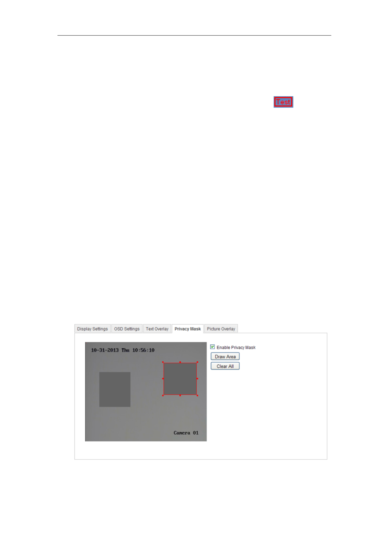
User Manual of Network Camera
71
Figure 6-41 Text Overlay
2. Check the checkbox in front of textbox to enable the on-screen display.
3. Input the characters in the textbox.
4. (Optional)Use the mouse to click and drag the red text frame in the live
view window to adjust the text overlay position.
5. Click to save the settings. Save
Note: Up to 8 text overlays are configurable.
6.5.4 Configuring Privacy Mask
Purpose:
Privacy mask enables you to cover certain areas on the live video to prevent certain
spots in the surveillance area from being live viewed and recorded.
Steps:
1. Enter the Privacy Mask Settings interface:
Configuration > Advanced Configuration> Image > Privacy Mask
2. Check the checkbox of to enable this function. Enable Privacy Mask
3. Click Draw Area.
Figure 6-42 Privacy Mask Settings
4. Click and drag the mouse in the live video window to draw the mask area.

User Manual of Network Camera
72
Note: You are allowed to draw up to 4 areas on the same image.
5. Click Stop Drawing to finish drawing or click to clear all of the areas Clear All
you set without saving them.
6. Click to save the settings. Save
6.5.5 Configuring Picture Overlay
Purpose:
Picture overlay enables you to overlay a picture on the image. This function enables a
certain enterprise or users to overlay their logo on the image.
Note: The picture must be RGB24 bmp format and the maximum size of the picture in
is 128*128.
Steps:
1. Enter the Picture Overlay Settings interface:
Configuration > Advanced Configuration> Image > Picture Overlay
Figure 6-43 cture Overlay Pi
2. Click to select a picture. Browse
3. Click to upload it. Upload
4. Check checkbox to enable the function. Enable Picture Overlay
X Coordinate and Y Coordinate values are for the location of the picture on the image.
And the Picture width and height shows the size of the picture.

User Manual of Network Camera
73
6.6 Configuring and Handling Alarms
This section explains how to configure the network camera to respond to alarm events,
including motion detection, video tampering, alarm input, alarm output, exception,
face detection, audio exception detection, intrusion detection, defocus detection, and
scene change detection, etc. These events can trigger the linkage methods, such as
Notify Surveillance Center, Send Email, Trigger Alarm Output, etc.
Notes:
Check the checkbox of Notify Surveillance Center if you want the alarm
information to be pushed to PC or mobile client software as soon as the alarm is
triggered.
Click for help when you configure the intelligent functions, including face
detection, audio exception detection, intrusion detection, defocus detection, scene
change detection, etc. A help document will guide you to go through the
configuration steps.
6.6.1 Configuring Motion Detection
Purpose:
Motion detection detects the moving objects in the configured surveillance area, and a
series of actions can be taken when the alarm is triggered..
In order to detect the moving objects accurately and reduce the false alarm rate,
normal configuration and expert configuration are selectable for different motion
detection environment.
Normal Configuration
Normal configuration adopts the same one set of motion detection parameters in the
day and at night. time
Tasks:
1. Set the Motion Detection Are a.
Steps:

User Manual of Network Camera
74
(1)Enter the motion detection settings interface
Configuration > Advanced Configuration> Basic Event > Motion
Detection
(2)Check the checkbox of . Enable Motion Detection
(3)Check the checkbox of Enable Dynamic Analysis for Motion if you want to
mark the detected objects with green rectangle s.
Note: Select Disable for rules t want the detected objected if you don’
displayed with the rectangles. Select disable from Configuration-Local
Configuration-Live View Parameters-rules.
Figure 6-44 Enable Motion Detection
(4)Click Draw Area. Click and drag the mouse on the live video to draw a
motion detection area.
(5)Click Stop Drawing to finish drawing one area.
(6)(Optional) Click Clear All clear all of the areas. to
(7)(Optional) Move the slider to set the sensitivity of the detection.
2. Set the Arming Schedule for Motion Detection.
Steps:
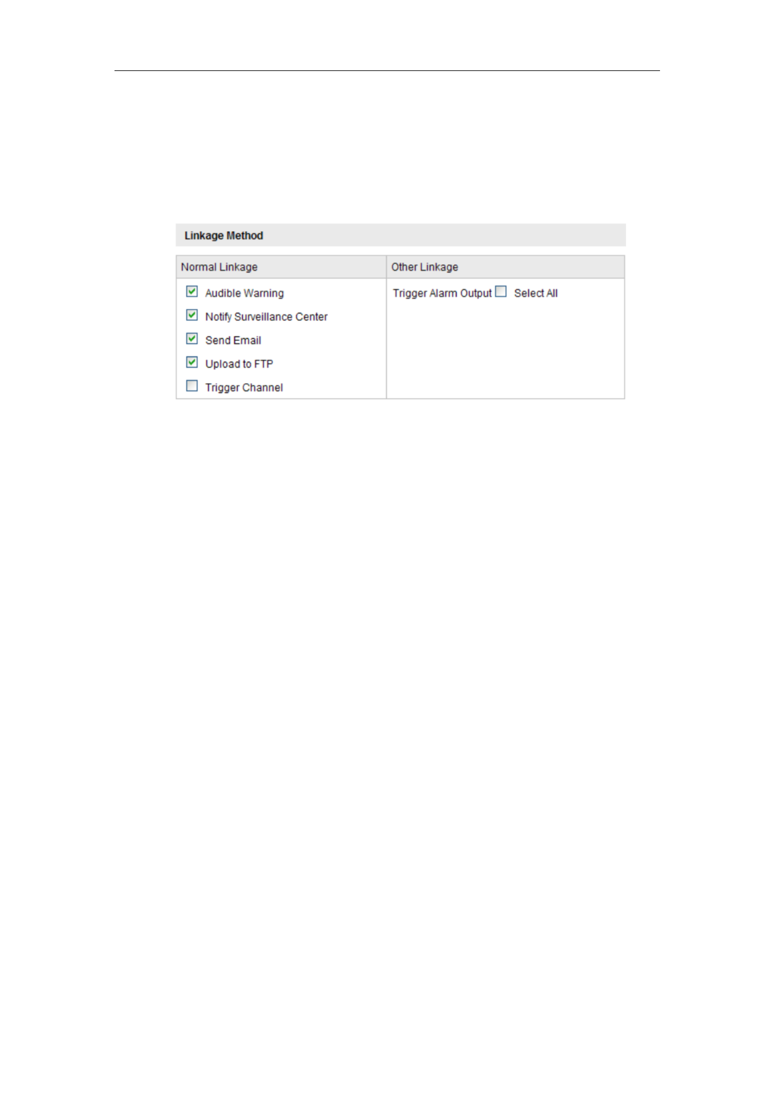
User Manual of Network Camera
76
3. Set the Alarm Actions for Motion Detection.
Check the checkbox to select the linkage method. Notify surveillance center,
send email, upload to FTP, trigger channel and trigger alarm output are selectable.
You can specify the linkage method when an event occurs.
Figure 6-47 Linkage Method
Audible Warning
Trigger the audible warning locally. And it only supported by the device have
the audio output.
Notify Surveillance Center
Send an exception or alarm signal to remote management software when an
event occurs.
Send Email
Send an email with alarm information to a user or users when an event occurs.
Note: To send the Email when an event occurs, you need to refer to Section
6.3.10 Email Sending Triggered by Alarm to set the related parameters.
Upload to FTP
Capture the image when an alarm is triggered and upload the picture to a FTP
server.
Notes:
Set the FTP address and the remote FTP server first. Refer to Section 6.3.12
Configuring FTP Settings for detailed information.
Go to Advanced Configuration > Storage > Snapshot page, enable the
event-triggered snapshot, and set the capture interval and capture number.

User Manual of Network Camera
77
The captured image can also be uploaded to the available SD card or network
disk.
Trigger Channel
The video will be recorded when the motion is detected. You have to set the
recording schedule to realize this function. Please refer to for Section 7.2
detailed information.
Trigger Alarm Output
Trigger one or more external alarm outputs when an event occurs.
Note: To trigger an alarm output when an event occurs, please refer to Section
6.6.4 Configuring Alarm Output to set the related parameters.
Expert Configuration
Expert mode is mainly used to configure the sensitivity and proportion of object on
area of each area for different day/night switch.
Figure 6-48 Expert Mode of Motion Detection
Day/Night Switch OFF
Steps:
(1)Draw the detection area as in the normal configuration mode. Up to 8 areas are
supported.
(2)Select for . OFF Switch Day and Night Settings

User Manual of Network Camera
78
(3)Select the area by clicking the area No..
(4)Slide the cursor to adjust the sensitivity and proportion of object on the area
for the selected area.
(5)Set the arming schedule and linkage method as in the normal configuration
mode.
(6)Click to save the settings. Save
Day/Night Auto-Switch
Steps:
(1)Draw the detection area as in the normal configuration mode. Up to 8 areas are
supported.
(2)Select Auto-Switch Switch Day and Night Settings for .
Figure 6-49 Day/Night Auto-Switch
(3)Select the area by clicking the area No.
(4)Slide the cursor to adjust the sensitivity and proportion of object on the area
for the selected area in the daytime.
(5)Slide the cursor to adjust the sensitivity and proportion of object on the area
for the selected area at night.
(6)Set the arming schedule and linkage method as in the normal configuration

User Manual of Network Camera
79
mode.
(7)Click to save the settings. Save
Day/Night Scheduled-Switch
(1)Draw the detection area as in the normal configuration mode. Up to 8 areas are
supported.
(2)Select for . Scheduled-Switch Switch Day and Night Settings
Figure 6-50 Day/Night Scheduled-Switch
(3)Select the start time and the end time for the switch timing.
(4)Select the area by clicking the area No.
(5)Slide the cursor to adjust the sensitivity and proportion of object on the area
for the selected area in the daytime.
(6)Slide the cursor to adjust the sensitivity and proportion of object on the area
for the selected area at night.
(7)Set the arming schedule and linkage method as in the normal configuration
mode.
(8)Click to save the settings. Save
6.6.2 Configuring Video Tampering Alarm
Purpose:
You can configure the camera to trigger the alarm when the lens is covered and take
some certain alarm response actions.
Steps:
1. Enter the video tampering Settings interface:
Configuration > Advanced Configuration > Basic Event > Video Tampering

User Manual of Network Camera
80
Figure 6-51 Video Tampering Alarm
2. Check Enable Video Tampering checkbox to enable the video tampering
detection.
3. Set the video tampering area. Refer to Task 1 Set the Motion Detection Area in
Section 6.6.1.
4. Click to edit the arming schedule for video tampering. The arming schedule Edit
configuration is the same as the setting of the arming schedule for motion
detection. Refer to Task 2 Set the Arming Schedule for Motion Detection in
Section 6.6.1.
5. Check the checkbox to select the linkage method taken for the video tampering .
Audible warning, notify surveillance center, send email and trigger alarm output
are selectable. Please refer to Task 3 Set the Alarm Actions for Motion Detection
in Section 6.6.1.
6. Click to save the settings. Save
6.6.3 Configuring Alarm Input
Steps:
1. Enter the Alarm Input Settings interface:
Configuration > Advanced Configuration> Basic Event > Alarm Input:

User Manual of Network Camera
81
2. Choose the alarm input No. and the Alarm Type. The alarm type can be NO
(Normally Open) and NC (Normally Closed). Edit the name to set a name for the
alarm input (optional).
Figure 6-52 Alarm Input Settings
3. Click to set the arming schedule for the alarm input. Refer to Edit Task 2 Set the
Arming Schedule for Motion Detection in Section 6.6.1.
4. Check the checkbox to select the linkage method taken for the alarm input. Refer
to Task 3 Set the Alarm Actions for Motion Detection in Section 6.6.1.
5. You can also choose the PTZ linking for the alarm input if your camera is
installed with a pan/tilt unit. Check the relative checkbox and select the No. to
enable Preset Calling, Patrol Calling or Pattern Calling.
6. You can copy your settings to other alarm inputs.
7. Click to save the settings. Save
6.6.4 Configuring Alarm Output
Steps:
1. Enter the Alarm Output Settings interface:
Configuration>Advanced Configuration> Basic Event > Alarm Output

User Manual of Network Camera
82
2. Select one alarm output channel in the drop-down list. You can Alarm Output
also set a name for the alarm output (optional).
3. The Delay time can be set to 5sec, 10sec, 30sec, 1min, 2min, 5min, 10min or
Manual The delay time refers to the time duration that the alarm output remains .
in effect after alarm occurs.
4. Click to enter the Edit Schedule Time interface. The time schedule Edit
configuration is the same as the settings of the arming schedule for motion
detection Refer to Task 2 Set the Arming Schedule for Motion Detection in
Section 6.6.1.
5. You can copy the settings to other alarm outputs.
6. Click to save the settings. Save
Figure 6-53 Alarm Output Settings
6.6.5 Handling Exception
The exception type can be HDD full, HDD error, network disconnected, IP address
conflicted and illegal login to the cameras.
Steps:

User Manual of Network Camera
83
1. Enter the Exception Settings interface:
Configuration > Advanced Configuration> Basic Event > Exception
2. Check the checkbox to set the actions taken for the Exception alarm. Refer to
Task 3 Set the Alarm Actions Taken for Motion Detection in Section 6.6.1.
Figure 6-54 Exception Settings
3. Click to save the settings. Save
6.6.6 Configuring Other Alarm
Note: Some certain cameras support Wireless Alarm, PIR (passive infrared sensor)
Alarm or Emergency Alarm.
Wireless Alarm
Purpose:
When wireless alarm signal is sent to the camera from the detector, such as the
wireless door contact, the wireless alarm is triggered and a series of response actions
can be taken.
Steps:
1. Enter the Wireless Alarm Settings interface:
Configuration > Advanced Configuration> Basic Event> Other Alarm
2. Select the wireless alarm number.
Up to 8 channels of external wireless alarm input are supported.
3. Check the checkbox of Enable Wireless Alarm to activate the wireless alarm.
4. Input the alarm name in the text field as desired.
5. Check the checkbox to select the linkage methods taken for the wireless alarm.
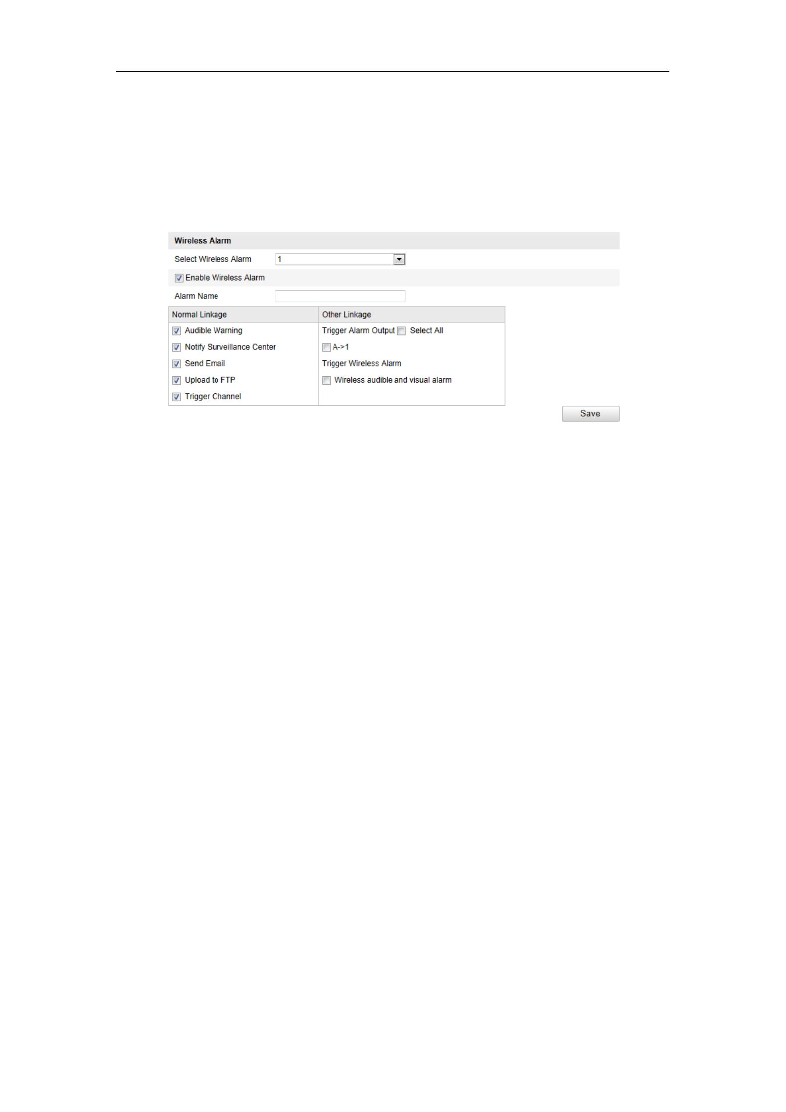
User Manual of Network Camera
84
6. Click to save the settings. Save
7. Locate the external wireless device beside the camera, and go to Configuration >
Advanced Configuration> System> Remote Control to arm the camera and
study the wireless alarm.
Figure 6-55 Configuring Wireless Alarm Settings
PIR Alarm
Purpose:
A PIR (Passive Infrared) alarm is triggered when an intruder moves within the
detector's field of view. The heat energy dissipated by a person, or any other warm
blooded creature such as dogs, cats, etc., can be detected.
Steps:
1. Enter the PIR Alarm Settings interface:
Configuration > Advanced Configuration> Basic Event> Other Alarm
2. Check the checkbox of to activate the PIR alarm function. Enable PIR Alarm
3. Input the alarm name in the text field as desired.
4. Check the checkbox to select the linkage methods taken for the PIR alarm.
5. Click the button to set the arming schedule. Edit
6. Click to save the settings. Save
7. Go to to Configuration > Advanced Configuration> System> Remote Control
arm the camera.

User Manual of Network Camera
85
Figure 6-56 Configuring PIR Alarm Settings
Emergency Alarm
Purpose:
You can press the Emergency button on the remote control to trigger the Emergency
Alarm in case of an emergency.
Note: The remote control is required for the Emergency Alarm. Go to
Configuration > Advanced Configuration> System> Remote Control to study the
remote control first.
Steps:
1. Enter the Emergency Alarm Settings interface:
Configuration > Advanced Configuration> Basic Event> Other Alarm
2. Check the checkbox to select the linkage methods taken for the Emergency alarm.
3. Click to save the settings. Save

User Manual of Network Camera
86
Figure 6-57 Configuring Emergency Alarm Settings
6.6.7 Configuring Audio Exception Detection
Purpose:
Audio exception detection function detects the abnormal sounds in the surveillance
scene, such as the sudden increase / decrease of the sound intensity, and some certain
actions can be taken when the alarm is triggered.
Note: Audio exception detection function varies according to different camera
models.
Steps:
1. Enter the Audio Exception Detection settings interface:
Configuration > Advanced Configuration> Smart Event> Audio Exception
Detection
2. Check the checkbox of to enable the audio loss detection Audio Loss Exception
function.
3. Check the checkbox of Sudden Increase of Sound Intensity Detection to detect
the sound steep rise in the surveillance scene. You can set the detection
sensitivity and threshold for sound steep rise.
4. Check the checkbox of Sudden Decrease of Sound Intensity Detection to detect
the sound steep drop in the surveillance scene. You can set the detection
sensitivity and threshold for sound steep drop.
Notes:
Sensitivity: Range [1-100], the smaller the value is, the more severe the
change should be to trigger the detection.

User Manual of Network Camera
87
Sound Intensity Threshold: Range [1-100], it can filter the sound in the
environment, the louder the environment sound, the higher the value should
be. You can adjust it according to the real environment.
5. You can view the real-time volume of the sound.
6. Click the button to set the arming schedule. Edit
7. Select the linkage methods for audio exception, including Notify Surveillance
Center, Send Email, Upload to FTP, Trigger Channel for recording and Trigger
Alarm Output.
8. Click to save the settings. Save
Figure 6-58 Configuring Audio Exception Detection
6.6.8 Configuring Defocus Detection
Purpose:
The image blur caused by defocus of the lens can be detected, and some certain
actions can be taken when the alarm is triggered.
Note: Defocus detection function varies according to different camera models.
Steps:
1. Enter the Defocus Detection settings interface:
Configuration> Advanced Configuration> Smart Event> Defocus Detection
2. Check the checkbox of to enable the function. Enable Defocus Detection
3. Click-and-drag the slider to set the detection sensitivity. The sensitivity value
ranges from 1 to 100, and the higher the value is, the more easily the defocus
image can trigger the alarm.
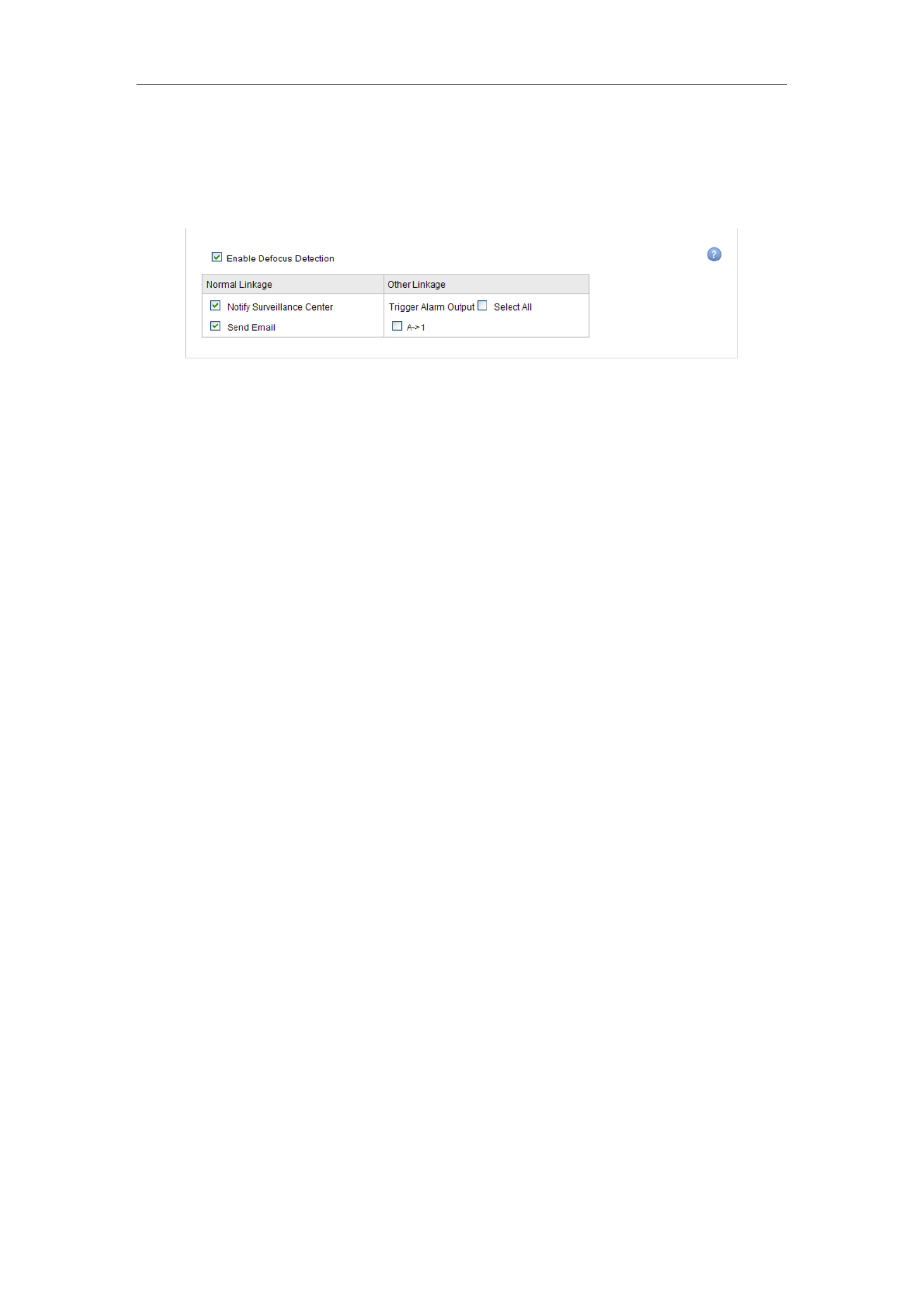
User Manual of Network Camera
88
4. Select the linkage methods for defocus, including Notify Surveillance Center,
Send Email and Trigger Alarm Output.
5. Click to save the settings. Save
Figure 6-59 Configuring Defocus Detection
6.6.9 Configuring Scene Change Detection
Purpose:
Scene change detection function detects the change of surveillance environment
affected by the external factors; such as the intentional rotation of the camera, and
some certain actions can be taken when the alarm is triggered.
Note: Scene change detection function varies according to different camera models.
Steps:
1. Enter the Scene Change Detection settings interface:
Configuration> Advanced Configuration> Smart Event> Scene Change
Detection
2. Check the checkbox of to enable the function. Enable Scene Change Detection
3. Click-and-drag the slider to set the detection sensitivity. The sensitivity value
ranges from 1 to 100, and the higher the value is, the more easily the change of
scene can trigger the alarm.
4. Click the button to set the arming schedule. Edit
5. Select the linkage methods for scene change, including Notify Surveillance
Center, Send Email, Upload to FTP, Trigger Channel and Trigger Alarm Output.
6. Click to save the settings. Save

User Manual of Network Camera
89
Figure 6-60 Configuring Scene Change Detection
6.6.10 Configuring Face Detection
Purpose:
Face detection function detects the face appears in the surveillance scene, and some
certain actions can be taken when the alarm is triggered.
Note: Face detection function varies according to different camera models.
Steps:
1. Enter the Face Detection settings interface:
Configuration> Advanced Configuration> Smart Event> Face Detection
2. Check the checkbox of to enable the function. Enable Face Detection
3. (Optional) Check the checkbox of Enable Dynamic Analysis for Face
Detection, and then the detected face is marked with green rectangle on the live
video.
Note: To mark the detected face on the live video, go to Local Configuration>
Live View Parameters and enable the Rules.
4. Click-and-drag the slider to set the detection sensitivity.
Sensitivity: Range [1-5]. The higher the value is, the more easily the face can be
detected.

User Manual of Network Camera
90
5. Click the button to set the arming schedule. Edit
6. Select the linkage methods for face detection, including Notify Surveillance
Center, Send Email, Upload to FTP, Trigger Channel and Trigger Alarm Output.
7. Click to save the settings. Save
Figure 6-61 Configuring Face Detection
6.6.11 Configuring Line Crossing Detection
Purpose:
Line crossing detection function detects people, vehicle or other objects which cross a
pre-defined virtual line, and some certain actions can be taken when the alarm is
triggered.
Note: Line crossing detection function varies according to different camera models.
Steps:

User Manual of Network Camera
91
1. Enter the Line Crossing Detection settings interface:
Configuration> Advanced Configuration> Smart Event> Line Crossing
Detection
2. Check the checkbox of to enable the function. Enable Line Crossing Detection
3. Select the line from the drop-down list for detection settings.
4. Click the button, and a virtual line is displayed on the live video. Draw Area
5. Click-and-drag the line, and you can locate it on the live video as desired. Click
on the line, two red squares are displayed on each end, and you can
click-and-drag one of the red squares to define the shape and length of the line.
6. Select the direction for line crossing detection. And you can select the directions
as A<->B, A ->B, and B- . >A
A<->B: Only the arrow on the B side shows; when an object going across the plane
with both direction can be detected and alarms are triggered.
A->B: Only the object crossing the configured line from the A side to the B side
can be detected.
B->A: Only the object crossing the configured line from the B side to the A side
can be detected.
7. Click-and-drag the slider to set the detection sensitivity.
Sensitivity: Range [1-100]. The higher the value is, the more easily the line
crossing action can be detected.
8. Repeat the above steps to configure other lines. Up to 4 lines can be set. You can
click the button to clear all pre-defined lines. Clear
9. Click the button to set the arming schedule. Edit
10. Select the linkage methods for line crossing detection, including Notify
Surveillance Center, Send Email, Upload to FTP, Trigger Channel and Trigger
Alarm Output.
11. Click to save the settings. Save

User Manual of Network Camera
92
Figure 6-62 Draw Crossing Line
6.6.12 Configuring Intrusion Detection
Purpose:
Intrusion detection function detects people, vehicle or other objects which enter and
loiter in a pre-defined virtual region, and some certain actions can be taken when the
alarm is triggered.
Note: Intrusion detection function varies according to different camera models.
Steps:
1. Enter the Intrusion Detection settings interface:
Configuration> Advanced Configuration> Smart Event> Intrusion Detection
2. Check the checkbox of to enable the function. Enable Intrusion Detection
3. Select the region from the drop-down list for detection settings.
4. Click the button to start the region drawing. Draw Area
5. Click on the live video to specify the four vertexes of the detection region, and
right click to complete drawing.

User Manual of Network Camera
93
6. Set the time threshold, detection sensitivity and object percentage for intrusion
detection.
Threshold: Range [0s-10s], the threshold for the time of the object loitering in
the region. If you set the value as 0, alarm is triggered immediately after the
object entering the region.
Sensitivity: Range -100]. The value of the sensitivity defines the size of the [1
object which can trigger the alarm. When the sensitivity is high, a very small
object can trigger the alarm.
Percentage: Range [1-100]. Percentage defines the ratio of the in-region part of
the object which can trigger the alarm. For example, if the percentage is set as
50%, when the object enters the region and occupies half of the whole region, the
alarm is triggered.
7. Repeat the above steps to configure other regions. Up to 4 regions can be set. You
can click the button to clear all pre-defined regions. Clear
8. Click the button to set the arming schedule. Edit
9. Select the linkage methods for intrusion detection, including Notify Surveillance
Center, Send Email, Upload to FTP, Trigger Channel and Trigger Alarm Output.
10. Click to save the settings. Save
Figure 6-63 Configuring Intrusion Area

User Manual of Network Camera
94
6.6.13 Configuring Region Entrance Detection
Purpose:
Region entrance detection function detects people, vehicle or other objects which
enter a pre-defined virtual region from the outside place, and some certain actions can
be taken when the alarm is triggered.
Note: Region entrance detection function varies according to different camera models.
Steps:
1. Enter the Region Entrance Detection settings interface:
Configuration> Advanced Configuration> Smart Event> Region Entrance
Detection
2. Check the checkbox of Enable Region Entrance Detection to enable the
function.
3. Select the region from the drop-down list for detection settings.
4. Click the button to start the region drawing. Draw Area
5. ick on the live video to specify the four vertexes of the detection region, and Cl
right click to complete drawing.
6. Click-and-drag the slider to set the detection sensitivity.
Sensitivity: Range [1-100]. The value of the sensitivity defines the size of the
object which can trigger the alarm. When the sensitivity is high, a very small
object entering the region can trigger the alarm.
7. Repeat the above steps to configure other regions. Up to 4 regions can be set. You
can click the Clear button to clear all pre-defined regions.
8. Click the button to set the arming schedule. Edit
9. Select the linkage methods for region entrance detection, including Notify
Surveillance Center, Send Email, Upload to FTP, Trigger Channel and Trigger
Alarm Output.
10. Click to save the settings. Save
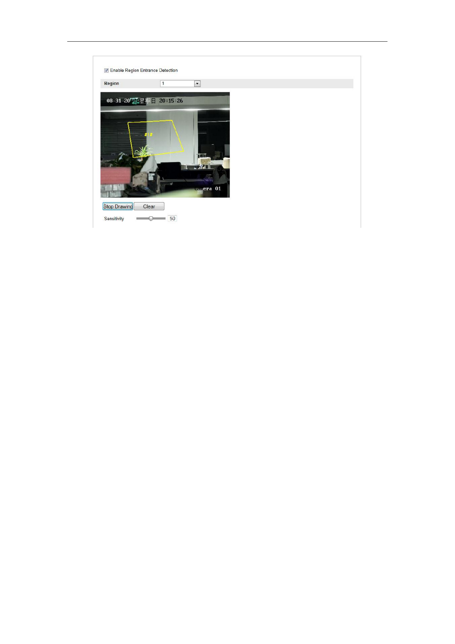
User Manual of Network Camera
95
Figure 6-64 Configuring Region Entrance Detection
6.6.14 Configuring Region Exiting Detection
Purpose:
Region exiting detection function detects people, vehicle or other objects which exit
from a pre-defined virtual region, and some certain actions can be taken when the
alarm is triggered.
Note: Region exiting detection function varies according to different camera models.
Steps:
1. Enter the Region Exiting Detection settings interface:
Configuration> Advanced Configuration> Smart Event> Region Exiting
Detection
2. Check the checkbox of to enable the function. Enable Region Exiting Detection
3. Select the region from the drop-down list for detection settings.
4. Click the button to start the region drawing. Draw Area
5. Click on the live video to specify the four vertexes of the detection region, and
right click to complete drawing.
6. Click-and-drag the slider to set the detection sensitivity.
Sensitivity: Range [1-100]. The value of the sensitivity defines the size of the
Produktspezifikationen
| Marke: | Hikvision |
| Kategorie: | Überwachungskamera |
| Modell: | DS-2CD6424FWD-20 |
Brauchst du Hilfe?
Wenn Sie Hilfe mit Hikvision DS-2CD6424FWD-20 benötigen, stellen Sie unten eine Frage und andere Benutzer werden Ihnen antworten
Bedienungsanleitung Überwachungskamera Hikvision

13 Oktober 2024
13 Oktober 2024
13 Oktober 2024
11 Oktober 2024
11 Oktober 2024
11 Oktober 2024
8 Oktober 2024
3 Oktober 2024
3 Oktober 2024
2 Oktober 2024
Bedienungsanleitung Überwachungskamera
- Überwachungskamera Samsung
- Überwachungskamera Approx
- Überwachungskamera Belkin
- Überwachungskamera Sanyo
- Überwachungskamera Exibel
- Überwachungskamera Gembird
- Überwachungskamera Genius
- Überwachungskamera Hama
- Überwachungskamera LogiLink
- Überwachungskamera Logitech
- Überwachungskamera Manhattan
- Überwachungskamera Nedis
- Überwachungskamera Niceboy
- Überwachungskamera Philips
- Überwachungskamera Sony
- Überwachungskamera Trust
- Überwachungskamera Panasonic
- Überwachungskamera Clas Ohlson
- Überwachungskamera Profile
- Überwachungskamera ZyXEL
- Überwachungskamera Bosch
- Überwachungskamera Laserliner
- Überwachungskamera Buffalo
- Überwachungskamera Canon
- Überwachungskamera Velleman
- Überwachungskamera Powerfix
- Überwachungskamera Eminent
- Überwachungskamera Linksys
- Überwachungskamera Maginon
- Überwachungskamera Netgear
- Überwachungskamera Technaxx
- Überwachungskamera Alecto
- Überwachungskamera Denver
- Überwachungskamera EMOS
- Überwachungskamera Gira
- Überwachungskamera König
- Überwachungskamera MarQuant
- Überwachungskamera Renkforce
- Überwachungskamera Thomson
- Überwachungskamera Trevi
- Überwachungskamera Blaupunkt
- Überwachungskamera Schneider
- Überwachungskamera Trebs
- Überwachungskamera Pyle
- Überwachungskamera Topcom
- Überwachungskamera Pioneer
- Überwachungskamera JVC
- Überwachungskamera Motorola
- Überwachungskamera Xiaomi
- Überwachungskamera Abus
- Überwachungskamera Avidsen
- Überwachungskamera Elro
- Überwachungskamera EZVIZ
- Überwachungskamera Imou
- Überwachungskamera INSTAR
- Überwachungskamera Megasat
- Überwachungskamera Olympia
- Überwachungskamera Smartwares
- Überwachungskamera Switel
- Überwachungskamera Yale
- Überwachungskamera Ferguson
- Überwachungskamera Orion
- Überwachungskamera Gigaset
- Überwachungskamera Strong
- Überwachungskamera Toshiba
- Überwachungskamera Garmin
- Überwachungskamera Perel
- Überwachungskamera Netis
- Überwachungskamera Lindy
- Überwachungskamera Fenton
- Überwachungskamera Waeco
- Überwachungskamera Acme
- Überwachungskamera Burg Wächter
- Überwachungskamera Marmitek
- Überwachungskamera Marshall
- Überwachungskamera Honeywell
- Überwachungskamera B/R/K
- Überwachungskamera Marshall Electronics
- Überwachungskamera TRENDnet
- Überwachungskamera Targa
- Überwachungskamera First Alert
- Überwachungskamera AVerMedia
- Überwachungskamera Zebra
- Überwachungskamera TP-Link
- Überwachungskamera Flamingo
- Überwachungskamera Kodak
- Überwachungskamera Rollei
- Überwachungskamera IGet
- Überwachungskamera Adj
- Überwachungskamera Netatmo
- Überwachungskamera Duramaxx
- Überwachungskamera Ebode
- Überwachungskamera Xavax
- Überwachungskamera InFocus
- Überwachungskamera Overmax
- Überwachungskamera Monoprice
- Überwachungskamera Monacor
- Überwachungskamera JUNG
- Überwachungskamera Ednet
- Überwachungskamera AG Neovo
- Überwachungskamera Nest
- Überwachungskamera Edimax
- Überwachungskamera V-TAC
- Überwachungskamera Aritech
- Überwachungskamera Uniden
- Überwachungskamera Kogan
- Überwachungskamera Genie
- Überwachungskamera M-e
- Überwachungskamera Elmo
- Überwachungskamera Lumens
- Überwachungskamera Jablocom
- Überwachungskamera Conceptronic
- Überwachungskamera D-Link
- Überwachungskamera Eufy
- Überwachungskamera Stabo
- Überwachungskamera Friedland
- Überwachungskamera EVOLVEO
- Überwachungskamera SPC
- Überwachungskamera August
- Überwachungskamera Ring
- Überwachungskamera Digitus
- Überwachungskamera SereneLife
- Überwachungskamera Swann
- Überwachungskamera Vitek
- Überwachungskamera DataVideo
- Überwachungskamera LevelOne
- Überwachungskamera Aida
- Überwachungskamera APC
- Überwachungskamera Beafon
- Überwachungskamera Chuango
- Überwachungskamera Cisco
- Überwachungskamera Grandstream
- Überwachungskamera Delta Dore
- Überwachungskamera EVE
- Überwachungskamera Defender
- Überwachungskamera Tenda
- Überwachungskamera Swisstone
- Überwachungskamera Foscam
- Überwachungskamera Ubiquiti Networks
- Überwachungskamera Kramer
- Überwachungskamera Vaddio
- Überwachungskamera Intellinet
- Überwachungskamera Reolink
- Überwachungskamera Swan
- Überwachungskamera FLIR
- Überwachungskamera Furrion
- Überwachungskamera Arlo
- Überwachungskamera Nexxt
- Überwachungskamera Planet
- Überwachungskamera EnGenius
- Überwachungskamera Dörr
- Überwachungskamera Lorex
- Überwachungskamera Ikan
- Überwachungskamera Comtrend
- Überwachungskamera Somfy
- Überwachungskamera Dahua
- Überwachungskamera Dedicated Micros
- Überwachungskamera DIO
- Überwachungskamera EasyN
- Überwachungskamera Escam
- Überwachungskamera EverFocus
- Überwachungskamera Ganz
- Überwachungskamera GeoVision
- Überwachungskamera Hombli
- Überwachungskamera Home Protector
- Überwachungskamera Iiquu
- Überwachungskamera Indexa
- Überwachungskamera Interlogix
- Überwachungskamera KlikaanKlikuit
- Überwachungskamera Kompernass
- Überwachungskamera Mr Safe
- Überwachungskamera Naxa
- Überwachungskamera Nordval
- Überwachungskamera Notifier
- Überwachungskamera Oplink
- Überwachungskamera Provision ISR
- Überwachungskamera Quantum
- Überwachungskamera Raymarine
- Überwachungskamera Revo
- Überwachungskamera SAB
- Überwachungskamera Satel
- Überwachungskamera SecurityMan
- Überwachungskamera Sinji
- Überwachungskamera SMC
- Überwachungskamera Sonic Alert
- Überwachungskamera Sricam
- Überwachungskamera Steren
- Überwachungskamera Storage Options
- Überwachungskamera Tenvis
- Überwachungskamera Hive
- Überwachungskamera Ubiquiti
- Überwachungskamera Vivotek
- Überwachungskamera Woonveilig
- Überwachungskamera Y-cam
- Überwachungskamera ACTi
- Überwachungskamera AVer
- Überwachungskamera Epcom
- Überwachungskamera ZKTeco
- Überwachungskamera AirLive
- Überwachungskamera Mobotix
- Überwachungskamera Dahua Technology
- Überwachungskamera Speco Technologies
- Überwachungskamera 3xLOGIC
- Überwachungskamera Atlantis Land
- Überwachungskamera CRUX
- Überwachungskamera Pentatech
- Überwachungskamera Summer Infant
- Überwachungskamera Illustra
- Überwachungskamera Surveon
- Überwachungskamera Avigilon
- Überwachungskamera Brilliant
- Überwachungskamera Hanwha
- Überwachungskamera Lanberg
- Überwachungskamera Verint
- Überwachungskamera Axis
- Überwachungskamera EtiamPro
- Überwachungskamera MEE Audio
- Überwachungskamera Advantech
- Überwachungskamera Chacon
- Überwachungskamera Alula
- Überwachungskamera EKO
- Überwachungskamera IOIO
- Überwachungskamera KJB Security Products
- Überwachungskamera BZBGear
- Überwachungskamera Adesso
- Überwachungskamera Brickcom
- Überwachungskamera Insteon
- Überwachungskamera Aigis
- Überwachungskamera Pelco
- Überwachungskamera ORNO
- Überwachungskamera Atlona
- Überwachungskamera Linear PRO Access
- Überwachungskamera Laxihub
- Überwachungskamera Valueline
- Überwachungskamera Aqara
- Überwachungskamera Tecno
- Überwachungskamera Lutec
- Überwachungskamera Brinno
- Überwachungskamera Night Owl
- Überwachungskamera WyreStorm
- Überwachungskamera Exacq
- Überwachungskamera Equip
- Überwachungskamera AVMATRIX
- Überwachungskamera UniView
- Überwachungskamera Alfatron
- Überwachungskamera Syscom
- Überwachungskamera BLOW
- Überwachungskamera Videotec
- Überwachungskamera DSC
- Überwachungskamera AViPAS
- Überwachungskamera Milestone Systems
- Überwachungskamera Inkovideo
- Überwachungskamera Hamlet
- Überwachungskamera Mobi
- Überwachungskamera Infortrend
- Überwachungskamera VideoComm
- Überwachungskamera Kguard
- Überwachungskamera Boyo
- Überwachungskamera HiLook
- Überwachungskamera Mach Power
- Überwachungskamera Canyon
- Überwachungskamera Digital Watchdog
- Überwachungskamera Ernitec
- Überwachungskamera Ikegami
- Überwachungskamera Gewiss
- Überwachungskamera Weldex
- Überwachungskamera Costar
- Überwachungskamera Sentry360
- Überwachungskamera ALC
- Überwachungskamera Spyclops
- Überwachungskamera Compro
- Überwachungskamera IDIS
- Überwachungskamera I3International
- Überwachungskamera B & S Technology
- Überwachungskamera Qian
- Überwachungskamera Accsoon
- Überwachungskamera Control4
- Überwachungskamera Petcube
- Überwachungskamera Apeman
- Überwachungskamera ATN
- Überwachungskamera IC Intracom
- Überwachungskamera POSline
- Überwachungskamera Watec
- Überwachungskamera ETiger
- Überwachungskamera Videcon
- Überwachungskamera BirdDog
- Überwachungskamera Topica
- Überwachungskamera Rostra
- Überwachungskamera Caddx
- Überwachungskamera Whistler
- Überwachungskamera ClearView
- Überwachungskamera Beseye
- Überwachungskamera IMILAB
- Überwachungskamera CNB Technology
- Überwachungskamera Tapo
- Überwachungskamera Securetech
- Überwachungskamera NetMedia
- Überwachungskamera Nivian
- Überwachungskamera Guardzilla
- Überwachungskamera Blink
- Überwachungskamera Zavio
- Überwachungskamera Campark
- Überwachungskamera IPX
- Überwachungskamera Annke
- Überwachungskamera AVTech
- Überwachungskamera Vimtag
- Überwachungskamera Security Labs
- Überwachungskamera Seneca
- Überwachungskamera Vosker
- Überwachungskamera Owltron
- Überwachungskamera Enabot
- Überwachungskamera Luis Energy
- Überwachungskamera Sir Gawain
- Überwachungskamera VisorTech
- Überwachungskamera Milesight
- Überwachungskamera GVI Security
- Überwachungskamera Conbrov
- Überwachungskamera HuddleCamHD
- Überwachungskamera Setti+
- Überwachungskamera BIRDFY
- Überwachungskamera I-PRO
- Überwachungskamera DVDO
- Überwachungskamera TCP
Neueste Bedienungsanleitung für -Kategorien-

15 Oktober 2024

15 Oktober 2024
14 Oktober 2024
14 Oktober 2024
10 Oktober 2024
9 Oktober 2024
9 Oktober 2024
8 Oktober 2024
7 Oktober 2024
6 Oktober 2024