Gigabyte X570 Aorus Elite Wifi Bedienungsanleitung
Gigabyte
Hauptplatine
X570 Aorus Elite Wifi
Lesen Sie kostenlos die 📖 deutsche Bedienungsanleitung für Gigabyte X570 Aorus Elite Wifi (48 Seiten) in der Kategorie Hauptplatine. Dieser Bedienungsanleitung war für 17 Personen hilfreich und wurde von 2 Benutzern mit durchschnittlich 4.5 Sternen bewertet
Seite 1/48

For more product details, please visit GIGABYTE's website.
To reduce the impacts on global warming, the packaging materials of this product
are recyclable and reusable. GIGABYTE works with you to protect the environment.
X570 AORUS ELITE WIFI X570 AORUS ELITE
X570 AORUS ELITE
X570 AORUS ELITE WIFI
User's Manual
Rev. 1002
12ME-X57AELT-1002R

Copyright
© 2019 GIGA-BYTE TECHNOLOGY CO., LTD. All rights reserved.
The trademarks mentioned in this manual are legally registered to their respective owners.
Disclaimer
Information in this manual is protected by copyright laws and is the property of GIGABYTE.
Changes to the specications and features in this manual may be made by GIGABYTE without prior
notice. No part of this manual may be reproduced, copied, translated, transmitted, or published in any
form or by any means without GIGABYTE's prior written permission.
For quick set-up of the product, read the Quick Installation Guide included with the product.
In order to assist in the use of this product, carefully read the User's Manual.
For product-related information, check on our website at: https://www.gigabyte.com
Identifying Your Motherboard Revision
The revision number on your motherboard looks like this: "REV: X.X." For example, "REV: 1.0" means
the revision of the motherboard is 1.0. Check your motherboard revision before updating motherboard
BIOS, drivers, or when looking for technical information.
Example:
Motherboard
X570 AORUS ELITE
Jun. 14, 2019
Jun. 14, 2019
Motherboard
X570 AORUS ELIT E

- 3 -
Motherboard
X570 AORUS ELITE WIFI
Jul. 26, 2019
Wireless Module Country Approvals:
Jul. 26, 2019
Motherboard
X570 AORUS ELITE WIFI

- 4 -
Table of Contents
X570 AORUS ELITE/X570 AORUS ELITE WIFI Motherboard Layout 5 ............................
Chapter 1 Hardware Installation 6 .....................................................................................
1-1 Installation Precautions 6 ....................................................................................
1-2 ProductSpecications ...................................................................................... 7
1-3 Installing the CPU .......................................................................................... 11
1-4 Installing the Memory 12 .....................................................................................
1-5 Installing an Expansion Card 12 .........................................................................
1-6 Back Panel Connectors 13 ..................................................................................
1-7 Internal Connectors 15 ........................................................................................
Chapter 2 BIOS Setup 24 ..................................................................................................
2-1 Startup Screen 24 ...............................................................................................
2-2 The Main Menu 25 ..............................................................................................
2-3 Favorites (F11) 26 ...............................................................................................
2-4 Tweaker .......................................................................................................... 27
2-5 Settings .......................................................................................................... 29
2-6 System Info. 34 ...................................................................................................
2-7 Boot ................................................................................................................ 35
2-8 Save & Exit 38 .....................................................................................................
Chapter 3 Appendix 39 ......................................................................................................
3-1 ConguringaRAIDSet .................................................................................. 39
3-2 DriversInstallation .......................................................................................... 41
Regulatory Statements 42 ..............................................................................................
Contact Us 48 ................................................................................................................

- 5 -
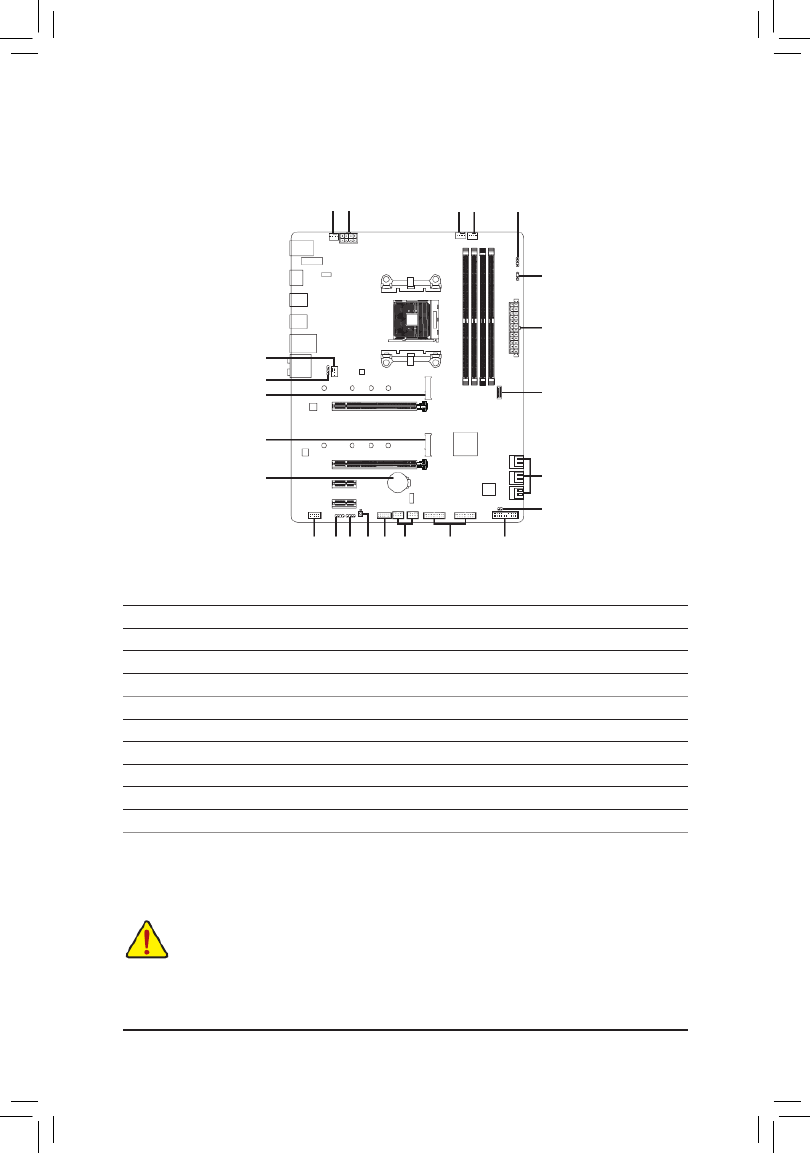
X570 AORUS ELITE/X570 AORUS ELITE WIFI Motherboard Layout
* The box contents above are for reference only and the actual items shall depend on the product package you obtain. The
box contents are subject to change without notice.
Box Contents
5X570 AORUS ELITE or X570 AORUS ELITE WIFI motherboard
5Motherboard driver disk 5One G Connector
5User's Manual 5M.2 screw(s)/M.2 standoff(s)
5Quick Installation Guide 5 jOne antenna
5Four SATA cables
R_USB1
CPU_FAN
ATX_12V
ATX
F_AUDIO
AUDIO
PCIEX4
DDR4_A2
DDR4_B2
F_USB31C
DDR4_A1
DDR4_B1
BAT
F_PANELQFLASH_PLUS
AMDX570
CLR_CMOS
M_BIOS
PCIEX16
F_USB30_2
USB 2.0 Hub
USB 2.0 Hub
Socket AM4
X570 AORUS ELITE
X570 AORUS ELITE WIFI
USB31_LAN
iTE®
Super I/O
F_USB2 F_USB1
TPM
M2A_SOCKET
SATA3
4 2 0
5 3 1
CPU_OPT
R_USB30_1
HDMI
Intel®
GbE LAN
PCIEX1_1
PCIEX1_2
LED_C1
80 60 42
F_USB30_1
D_LED1
SYS_FAN1
SYS_FAN2
LED_CPU
110
110
R_USB30_2
LED_C2
CODEC
M2B_SOCKET
80 60 42
D_LED2
QFLED
M2_WIFIj
jOnly for the X570 AORUS ELITE WIFI.

Chapter 1 Hardware Installation
1-1 Installation Precautions
The motherboard contains numerous delicate electronic circuits and components which can become
damagedasaresultofelectrostaticdischarge(ESD).Priortoinstallation,carefullyreadtheuser's
manual and follow these procedures:
•Prior to installation, make sure the chassis is suitable for the motherboard.
•Prior to installation, do not remove or break motherboard S/N (Serial Number) sticker or
warranty sticker provided by your dealer. These stickers are required for warranty validation.
•Always remove the AC power by unplugging the power cord from the power outlet before
installing or removing the motherboard or other hardware components.
•When connecting hardware components to the internal connectors on the motherboard, make
sure they are connected tightly and securely.
•When handling the motherboard, avoid touching any metal leads or connectors.
•It is best to wear an electrostatic discharge (ESD) wrist strap when handling electronic
componentssuchasamotherboard,CPUormemory.IfyoudonothaveanESDwriststrap,
keepyourhandsdryandrsttouchametalobjecttoeliminatestaticelectricity.
•Prior to installing the motherboard, please have it on top of an antistatic pad or within an
electrostatic shielding container.
•Before connecting or unplugging the power supply cable from the motherboard, make sure
the power supply has been turned off.
•Before turning on the power, make sure the power supply voltage has been set according to
the local voltage standard.
•Before using the product, please verify that all cables and power connectors of your hardware
components are connected.
•To prevent damage to the motherboard, do not allow screws to come in contact with the
motherboard circuit or its components.
•Make sure there are no leftover screws or metal components placed on the motherboard or
within the computer casing.
•Donotplacethecomputersystemonanunevensurface.
•Donotplacethecomputersysteminahigh-temperatureorwetenvironment.
•Turning on the computer power during the installation process can lead to damage to system
components as well as physical harm to the user.
•If you are uncertain about any installation steps or have a problem related to the use of the
product,pleaseconsultacertiedcomputertechnician.
•If you use an adapter, extension power cable, or power strip, ensure to consult with its installation
and/or grounding instructions.
- 6 -
1-2 ProductSpecications
CPU AMDSocketAM4,supportfor:
3rdGenerationAMDRyzen™ processors/
2ndGenerationAMDRyzen™ processors/
2ndGenerationAMDRyzen™ with Radeon™ Vega Graphics processors/
AMDRyzen™ with Radeon™
Vega Graphics processors
(Go to GIGABYTE's website for the latest CPU support list.)
Chipset AMDX570
Memory 3rdGenerationAMDRyzen™ processors:
- SupportforDDR43200/2933/2667/2400/2133MHzmemorymodules
2ndGenerationAMDRyzen™processors/2ndGenerationAMDRyzen
™ with Radeon™
VegaGraphicsprocessors/AMDRyzen™ with Radeon™ Vega Graphics processors:
- SupportforDDR42933/2667/2400/2133MHzmemorymodules
4xDDR4DIMMsocketssupportingupto128GB(32GBsingleDIMMcapacity)
of system memory
Dualchannelmemoryarchitecture
SupportforECCUn-bufferedDIMM1Rx8/2Rx8memorymodules
Supportfornon-ECCUn-bufferedDIMM1Rx8/2Rx8/1Rx16memorymodules
SupportforExtremeMemoryProle(XMP)memorymodules
(Go to GIGABYTE's website for the latest supported memory speeds and memory modules.)
Onboard
Graphics (Note 1)
Integrated Graphics Processor:
- 1xHDMIport,supportingamaximumresolutionof4096x2160@60Hz
* SupportforHDMI2.0version,HDCP2.2,andHDR.
Maximum shared memory of 16 GB
Audio Realtek® ALC1200 codec
HighDenitionAudio
2/4/5.1/7.1-channel
SupportforS/PDIFOut
LAN Intel® GbE LAN chip (10/100/1000 Mbit)
Wireless
Communication
Module j
Wi-Fi802.11a/b/g/n/ac,supporting2.4/5GHzDual-Band
BLUETOOTH 4.2
Support for 11ac wireless standard and up to 433 Mbps data rate
* Actual data rate may vary depending on environment and equipment.
(Note1) For2ndGenerationAMDRyzen™ with Radeon™
VegaGraphicsprocessors/AMDRyzen ™ with Radeon™
Vega Graphics processors only.
jOnly for the X570 AORUS ELITE WIFI.
- 7 -

Expansion Slots Integrated in the CPU (PCIEX16):
3rdGenerationAMDRyzen™ processors:
- 1 x PCI Express p8-x16 slot, supporting PCIe 4.0 and running at x16
2ndGenerationAMDRyzen™ processors:
- 1 x PCI Express p8-x16 slot, supporting PCIe 3.0 and running at x16
* For optimum performance, if only one PCI Express graphics card is to be installed,
be sure to install it in the PCIEX16 slot.
2ndGeneration AMD Ryzen
™ with Radeon™ Vega Graphics processors/AMD
Ryzen™ with Radeon™ Vega Graphics processors:
- 1 x PCI Express p8-x16 slot, supporting PCIe 3.0 and running at x8
Integrated in the Chipset (PCIEX4/PCIEX1):
- 1 x PCI Express p8-x16 slot, supporting PCIe 4.0
(Note 2)/3.0 and running at p8-x4
(PCIEX4)
- 2 x PCI Express p8-x1 slots, supporting PCIe 4.0
(Note 2)/3.0
Multi-Graphics
Technology (Note 3) SupportforAMDQuad-GPUCrossFire™and2-WayAMDCrossFire™ technologies
Storage Interface Integrated in the CPU (M2A_SOCKET):
3rdGenerationAMDRyzen™ processors:
- 1 x M.2 connector (Socket 3, M key, type 2242/2260/2280/22110 SATA and
PCIe4.0x4/x2SSDsupport)
2ndGenerationAMDRyzen™processors/2ndGenerationAMDRyzen
™ with Radeon™
VegaGraphicsprocessors/AMDRyzen™ with Radeon™
Vega Graphics processors:
- 1 x M.2 connector (Socket 3, M key, type 2242/2260/2280/22110 SATA and
PCIe3.0x4/x2SSDsupport)
Integrated in the Chipset (M2B_SOCKET):
- 1 x M.2 connector (Socket 3, M key, type 2242/2260/2280/22110 SATA and
PCIe 4.0 (Note 2)/3.0x4/x2SSDsupport)
- 6 x SATA 6Gb/s connectors
- SupportforRAID0,RAID1,andRAID10
USB Integrated in the CPU:
- 4 x USB 3.2 Gen 1 ports on the back panel
Integrated in the Chipset:
- 1 x USB Type-C™ port with USB 3.2 Gen 2 support, available through the
internal USB header
- 2 x USB 3.2 Gen 2 Type-A ports (red) on the back panel
- 4 x USB 3.2 Gen 1 ports available through the internal USB headers
Chipset+2 USB 2.0 Hubs:
- 8 x USB 2.0/1.1 ports (4 ports on the back panel, 4 ports available through
the internal USB headers)
(Note2) For3rdGenerationAMDRyzen™ processors only.
(Note3) For3rdGenerationAMDRyzen™processors/2ndGenerationAMDRyzen™ processors only.
- 8 -

Internal
Connectors
1 x 24-pin ATX main power connector
1 x 8-pin ATX 12V power connector
1 x CPU fan header
1 x water cooling CPU fan header
2 x system fan headers
2xaddressableLEDstripheaders
2xRGBLEDstripheaders
1xCPUcoolerLEDstrip/RGBLEDstripheader
2 x M.2 Socket 3 connectors
6 x SATA 6Gb/s connectors
1 x front panel header
1 x front panel audio header
1 x USB Type-C™ header, with USB 3.2 Gen 2 support
2 x USB 3.2 Gen 1 headers
2 x USB 2.0/1.1 headers
1 x Trusted Platform Module (TPM) header (2x6 pin, for the GC-TPM2.0_S
module only)
1 x Clear CMOS jumper
1 x Q-Flash Plus button
Back Panel
Connectors
4 x USB 2.0/1.1 ports
2 x SMA antenna connectors (1T1R)j
1xHDMIport
4 x USB 3.2 Gen 1 ports
2 x USB 3.2 Gen 2 Type-A ports (red)
1 x RJ-45 port
1xopticalS/PDIFOutconnector
5 x audio jacks
I/O Controller iTE® I/O Controller Chip
Hardware
Monitor
Voltage detection
Temperature detection
Fan speed detection
Watercoolingowratedetection
Overheating warning
Fan fail warning
Fan speed control
* Whether the fan speed control function is supported will depend on the fan you install.
BIOS 1x128Mbitash
Use of licensed AMI UEFI BIOS
PnP1.0a,DMI2.7,WfM2.0,SMBIOS2.7,ACPI5.0
jOnly for the X570 AORUS ELITE WIFI.
- 9 -

Unique Features Support for APP Center
* Available applications in APP Center may vary by motherboard model. Supported
functionsofeachapplicationmayalsovarydependingonmotherboardspecications.
- @BIOS
- AutoGreen
- Cloud Station
- EasyTune
- Fast Boot
- Game Boost
- ON/OFF Charge
- RGB Fusion
- Smart Backup
- Smart Keyboard
- Smart Survey
- System Information Viewer
- USB Blocker
Support for Q-Flash Plus
Support for Q-Flash
Support for Xpress Install
Bundled
Software
Norton® Internet Security (OEM version)
cFosSpeed
Operating
System Support for Windows 10 64-bit
Form Factor ATX Form Factor; 30.5cm x 24.4cm
* GIGABYTEreservestherighttomakeanychangestotheproductspecicationsandproduct-relatedinformationwithout
prior notice.
Please visit GIGABYTE's website for support lists of CPU, memory modules,
SSDs,andM.2devices.
Please visit the page on GIGABYTE's website to download the latest Support\Utility List
version of apps.
X570 AORUS ELITE WIFI X570 AORUS ELITE
- 10 -

Please visit GIGABYTE's website for details on hardware installation.
1-3 Installing the CPU
Read the following guidelines before you begin to install the CPU:
•Make sure that the motherboard supports the CPU.
(Go to GIGABYTE's website for the latest CPU support list.)
•Always turn off the computer and unplug the power cord from the power outlet before installing the
CPU to prevent hardware damage.
•Locate the pin one of the CPU. The CPU cannot be inserted if oriented incorrectly.
•Apply an even and thin layer of thermal grease on the surface of the CPU.
•DonotturnonthecomputeriftheCPUcoolerisnotinstalled,otherwiseoverheatinganddamage
of the CPU may occur.
•SettheCPUhostfrequencyinaccordancewiththeCPUspecications.Itisnotrecommended
thatthesystembusfrequencybesetbeyondhardwarespecicationssinceitdoesnotmeetthe
standard requirements for the peripherals. If you wish to set the frequency beyond the standard
specications,pleasedosoaccordingtoyourhardwarespecicationsincludingtheCPU,graphics
card, memory, hard drive, etc.
Installing the CPU
Locate the pin one (denoted by a small triangle) of the CPU socket and the CPU.
AM4 Socket
A Small Triangle Marking
DenotesPinOneoftheSocket AM4 CPU
A Small Triangle Marking
DenotesCPUPinOne
- 11 -

1-4 Installing the Memory
Read the following guidelines before you begin to install the memory:
•Make sure that the motherboard supports the memory. It is recommended that memory of the same
capacity, brand, speed, and chips be used.
(Go to GIGABYTE's website for the latest supported memory speeds and memory modules.)
•Always turn off the computer and unplug the power cord from the power outlet before installing the
memory to prevent hardware damage.
•Memory modules have a foolproof design. A memory module can be installed in only one direction.
If you are unable to insert the memory, switch the direction.
DualChannelMemoryConguration
ThismotherboardprovidesfourmemorysocketsandsupportsDualChannelTechnology.Afterthememory
isinstalled,theBIOSwillautomaticallydetectthespecicationsandcapacityofthememory.EnablingDual
Channel memory mode will double the original memory bandwidth.
1-5 Installing an Expansion Card
Read the following guidelines before you begin to install an expansion card:
•Make sure the motherboard supports the expansion card. Carefully read the manual that came
with your expansion card.
•Always turn off the computer and unplug the power cord from the power outlet before installing an
expansion card to prevent hardware damage.
The four memory sockets are divided into two channels and each channel has two memory sockets as following:
ChannelA:DDR4_A1,DDR4_A2
ChannelB:DDR4_B1,DDR4_B2
DuetoCPUlimitations,readthefollowingguidelinesbeforeinstallingthememoryinDualChannelmode.
1. DualChannelmodecannotbeenabledifonlyonememorymoduleisinstalled.
2. WhenenablingDualChannelmodewithtwoorfourmemorymodules,itisrecommendedthatmemory
of the same capacity, brand, speed, and chips be used. For optimum performance, when enabling
DualChannelmodewithtwomemorymodules,werecommendthatyouinstallthemintheDDR4_A2
andDDR4_B2sockets.
DualChannelMemoryCongurationsTable
DDR4_A1 DDR4_A2 DDR4_B1 DDR4_B2
2 Modules - - - -DS/SS DS/SS
DS/SS DS/SS- - - -
4 Modules DS/SS DS/SS DS/SS DS/SS
(SS=Single-Sided,DS=Double-Sided,"--"=NoMemory)
- 12 -
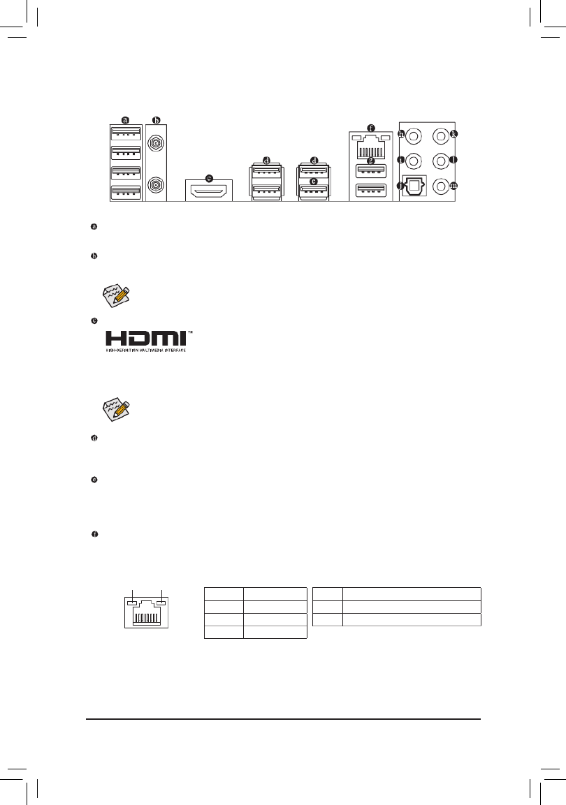
1-6 Back Panel Connectors
USB 2.0/1.1 Port
TheUSBportsupportstheUSB2.0/1.1specication.UsethisportforUSBdevices.
SMA Antenna Connectors (1T1R)j
Use this connector to connect an antenna.
Tighten the antenna cables to the antenna connectors and then move the antenna to a place
where the signal is good.
AfterinstallingtheHDMIdevice,makesuretosetthedefaultsoundplaybackdevicetoHDMI.(The
item name may differ depending on your operating system.)
HDMI Port (Note 1)
TheHDMIportisHDCP2.2compliantandsupportsDolbyTrueHDandDTS
HDMasterAudioformats.Italsosupportsupto192KHz/24bit8-channelLPCM
audiooutput.YoucanusethisporttoconnectyourHDMI-supportedmonitor.Themaximumsupported
resolution is 4096x2160@60 Hz, butthe actual resolutions supportedare dependent on themonitor
being used.
(Note1) For2ndGenerationAMDRyzen™ with Radeon™VegaGraphicsprocessors/AMDRyzen™ with Radeon™
Vega Graphics processors only.
(Note2) Toenable the Q-FlashPlus functionpleasevisitthe "UniqueFeatures" webpageofGIGABYTE's
website.
ActivityLED
Connection/
SpeedLED
LAN Port
ActivityLED:Connection/SpeedLED:
State Description
Orange 1 Gbps data rate
Green 100 Mbps data rate
Off 10 Mbps data rate
State Description
Blinking Datatransmissionorreceivingisoccurring
On No data transmission or receiving is occurring
USB 3.2 Gen 1 Port
TheUSB3.2Gen1portsupportstheUSB3.2Gen1specicationandiscompatibletotheUSB2.0
specication.UsethisportforUSBdevices.
USB 3.2 Gen 1 Port (White)
TheUSB3.2Gen1portsupportstheUSB3.2Gen1specicationandiscompatibletotheUSB2.0
specication.UsethisportforUSBdevices.BeforeusingQ-FlashPlus (Note 2), make sure to insert the USB
ashdriveintothisportrst.
RJ-45 LAN Port
The Gigabit Ethernet LAN port provides Internet connection at up to 1 Gbps data rate. The following
describesthestatesoftheLANportLEDs.
j
jOnly for the X570 AORUS ELITE WIFI.
- 13 -
1-7 Internal Connectors
Read the following guidelines before connecting external devices:
•First make sure your devices are compliant with the connectors you wish to connect.
•Before installing the devices, be sure to turn off the devices and your computer. Unplug the power
cord from the power outlet to prevent damage to the devices.
•After installing the device and before turning on the computer, make sure the device cable has
been securely attached to the connector on the motherboard.
1) ATX_12V
2) ATX
3) CPU_FAN
4) SYS_FAN1/2
5) CPU_OPT
6) M2A_SOCKET/M2B_SOCKET
7) SATA3 0/1/2/3/4/5
8) LED_C1/LED_C2
9) D_LED1/D_LED2
10) LED_CPU
11) F_AUDIO
12) F_PANEL
13) F_USB31C
14) F_USB30_1/F_USB30_2
15) F_USB1/F_USB2
16) TPM
17) BAT
18) CLR_CMOS
19) QFLASH_PLUS
2
19 168 12
4 1 3
6
4
10
15 14
5
7
13
6
18
911
17
9
8
- 15 -

131
2412
ATX
1/2) ATX_12V/ATX (2x4 12V Power Connector and 2x12 Main Power Connector)
With the use of the power connector, the power supply can supply enough stable power to all the components
onthemotherboard.Beforeconnectingthepowerconnector,rstmakesurethepowersupplyisturned
off and all devices are properly installed. The power connector possesses a foolproof design. Connect the
power supply cable to the power connector in the correct orientation.
The 12V power connector mainly supplies power to the CPU. If the 12V power connector is not connected,
the computer will not start.
To meet expansion requirements, it is recommended that a power supply that can withstand high
power consumption be used (500W or greater). If a power supply is used that does not provide the
required power, the result can lead to an unstable or unbootable system.
ATX:
Pin No. Pin No.Denition Denition
1 3.3V 13 3.3V
2 3.3V 14 -12V
3 15GND GND
4 +5V 16 PS_ON (soft On/Off)
5 17GND GND
6 +5V 18 GND
7 19GND GND
8 Power Good 20 NC
9 5VSB (stand by +5V) 21 +5V
10 +12V 22 +5V
11 +12V (Only for 2x12-pin
ATX)
23 +5V (Only for 2x12-pin ATX)
12 3.3V (Only for 2x12-pin
ATX)
24 GND(Onlyfor2x12-pin
ATX)
ATX_12V:
Pin No. Pin No.Denition Denition
1GND(Onlyfor2x4-pin
12V)
5 +12V (Only for 2x4-pin 12V)
2GND(Onlyfor2x4-pin
12V)
6 +12V (Only for 2x4-pin 12V)
3 7 +12VGND
4 8 +12VGND
ATX_12V
41
85
- 16 -

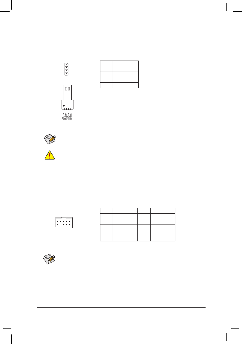
5) CPU_OPT (Water Cooling CPU Fan Header)
The fan header is 4-pin and possesses a foolproof insertion design. Most fan headers possess a foolproof
insertion design. When connecting a fan cable, be sure to connect it in the correct orientation (the black
connector wire is the ground wire). The speed control function requires the use of a fan with fan speed
control design.
1
1
CPU_FAN/SYS_FAN1
SYS_FAN2
Pin No. Denition
1GND
2 Voltage Speed Control
3 Sense
4 PWM Speed Control
3/4) CPU_FAN/SYS_FAN1/2 (Fan Headers)
All fan headers on this motherboard are 4-pin. Most fan headers possess a foolproof insertion design.
When connecting a fan cable, be sure to connect it in the correct orientation (the black connector wire is
the ground wire). The speed control function requires the use of a fan with fan speed control design. For
optimum heat dissipation, it is recommended that a system fan be installed inside the chassis.
•Be sure to connect fan cables to the fan headers to prevent your CPU and system from
overheating. Overheating may result in damage to the CPU or the system may hang.
•Thesefanheadersarenotcongurationjumperblocks.Donotplaceajumpercapontheheaders.
1
Pin No. Denition
1GND
2 Voltage Speed Control
3 Sense
4 PWM Speed Control
- 17 -

6) M2A_SOCKET/M2B_SOCKET (M.2 Socket 3 Connectors)
TheM.2connectorssupportM.2SATASSDsorM.2PCIeSSDsandsupportRAIDconguration.Please
notethatanM.2PCIeSSDcannotbeusedtocreateaRAIDseteitherwithanM.2SATASSDoraSATA
harddrive.RefertoChapter3,"ConguringaRAIDSet,"forinstructionsonconguringaRAIDarray.
SelecttheproperholefortheM.2SSDtobeinstalledandrefastenthescrewandstandoff.
_F
80110
110
60
M2A_SOCKET
80 60
M2B_SOCKET
42
42
FollowthestepsbelowtocorrectlyinstallanM.2SSDintheM.2connector.
Step 1:
Get a screw and a standoff from the included M.2 screw and standoff packs. Locate the M.2 connector
whereyouwillinstalltheM.2SSD,useascrewdrivertounfastenthescrewontheheatsinkandthen
remove the heatsink. (Only the M2A_SOCKET connector has the heatsink)
Step 2:
LocatethepropermountingholefortheM.2SSDtobeinstalledandthentightenthestandoffrst.Insert
theM.2SSDintotheM.2connectoratanangle.
Step 3:
PresstheM.2SSDdownandthensecureitwiththescrew.Replacetheheatsinkandsecureittothe
original hole.
7) SATA3 0/1/2/3/4/5 (SATA 6Gb/s Connectors)
The SATA connectors conform to SATA 6Gb/s standard and are compatible with SATA 3Gb/s and SATA
1.5Gb/s standard. Each SATA connector supports a single SATA device. The SATA connectors support
RAID0,RAID1,andRAID10.RefertoChapter3,"ConguringaRAIDSet,"forinstructionsonconguring
aRAIDarray.
Pin No. Denition
1GND
2 TXP
3 TXN
4GND
5 RXN
6 RXP
7GND
SATA3 420
531
1
1
7
7
- 18 -

8) LED_C1/LED_C2 (RGB LED Strip Headers)
Theheaderscanbeusedtoconnectastandard5050RGBLEDstrip(12V/G/R/B),withmaximumpower
rating of 2A (12V) and maximum length of 2m.
Pin No. Denition
1 12V
2 G
3 R
4 B
1
1
LED_C1 LED_C2
ConnectyourRGBLEDstriptotheheader.Thepowerpin(marked
withatriangleontheplug)oftheLEDstripmustbeconnectedto
Pin 1 (12V) of this header. Incorrect connection may lead to the
damageoftheLEDstrip.
Before installing the devices, be sure to turn off the devices and your computer. Unplug the power
cord from the power outlet to prevent damage to the devices.
Forhowtoturnon/offthelightsoftheLEDstrippleasevisitthe"UniqueFeatures"webpageof
GIGABYTE's website.
RGBLEDStrip
1
12V
Pin No. Denition
1 V (5V)
2D
3 No Pin
4 G
9) D_LED1/D_LED2 (Addressable LED Strip Headers)
Theheaderscanbeusedtoconnectastandard5050addressableLEDstrip,withmaximumpowerrating
of5A(5V)andmaximumnumberof1000LEDs.
Connect your addressableLED stripto the header. The power
pin(markedwithatriangleontheplug)oftheLEDstripmustbe
connectedtoPin1oftheaddressableLEDstripheader.Incorrect
connectionmayleadtothedamageoftheLEDstrip.
D_LED1 D_LED2
11
Addressable
LEDStrip
1
- 19 -
Before installing the devices, be sure to turn off the devices and your computer. Unplug the power
cord from the power outlet to prevent damage to the devices.
Forhowtoturnon/offthelightsoftheLEDstrippleasevisitthe"UniqueFeatures"webpageof
GIGABYTE's website.
Pin No. Denition
1 12V
2 G
3 R
4 B
1
10) LED_CPU (CPU Cooler LED Strip/RGB LED Strip Header)
TheheadercanbeusedtoconnectaCPUcoolerLEDstriporastandard5050RGBLEDstrip(12V/G/R/B),
with maximum power rating of 2A (12V) and maximum length of 2m.
ConnecttheCPUcoolerLEDstrip/RGBLEDstriptothe
header. The power pin (marked with a triangle on the plug)
oftheLEDstripmustbeconnectedtoPin1(12V)ofthis
header. Incorrect connection may lead to the damage of the
LEDstrip.
LEDStrip
1
12V
11) F_AUDIO (Front Panel Audio Header)
ThefrontpanelaudioheadersupportsHighDenitionaudio(HD).Youmayconnectyourchassisfront
panel audio module to this header. Make sure the wire assignments of the module connector match the
pin assignments of the motherboard header. Incorrect connection between the module connector and the
motherboard header will make the device unable to work or even damage it.
Some chassis provide a front panel audio module that has separated connectors on each wire
instead of a single plug. For information about connecting the front panel audio module that has
different wire assignments, please contact the chassis manufacturer.
Pin No. Pin No.Denition Denition
1 MIC2_L 6 Sense
2 7GND FAUDIO_JD
3 MIC2_R 8 No Pin
4 NC 9 LINE2_L
5 LINE2_R 10 Sense
9 1
10 2
- 20 -

The front panel design may differ by chassis. A front panel module mainly consists of power switch,
resetswitch,powerLED,harddriveactivityLED,speakerandetc.Whenconnectingyourchassis
front panel module to this header, make sure the wire assignments and the pin assignments are
matched correctly.
12) F_PANEL (Front Panel Header)
Connect the power switch, reset switch, speaker, chassis intrusion switch/sensor and system status indicator
on the chassis to this header according to the pin assignments below. Note the positive and negative pins
before connecting the cables.
System Status LED
S0 On
S3/S4/S5 Off
•PW (Power Switch):
Connects to the power switch on the chassis front panel. You may
congure the way to turn off your system using the power switch
(refertoChapter2,"BIOSSetup,""Settings\PlatformPower,"formore
information).
•SPEAK (Speaker):
Connects to the speaker on the chassis front panel. The system reports
system startup status by issuing a beep code. One single short beep
will be heard if no problem is detected at system startup.
•PLED/PWR_LED (PowerLED):
Connects to the power status indicator
onthechassisfrontpanel.TheLEDison
whenthesystemisoperating.TheLEDis
off when the system is in S3/S4 sleep state
or powered off (S5).
•HD (HardDriveActivityLED):
ConnectstotheharddriveactivityLEDonthechassisfrontpanel.TheLEDisonwhentheharddrive
is reading or writing data.
•RES (Reset Switch):
Connects to the reset switch on the chassis front panel. Press the reset switch to restart the computer
ifthecomputerfreezesandfailstoperformanormalrestart.
•CI (Chassis Intrusion Header):
Connects to the chassis intrusion switch/sensor on the chassis that can detect if the chassis cover has
been removed. This function requires a chassis with a chassis intrusion switch/sensor.
•NC: No Connection.
PowerLED
1
2
19
20
CI-
CI+
PWR_LED-
PWR_LED+
PLED-
PW-
SPEAK+
SPEAK-
PLED+
PW+
PowerLED
HD-
RES+
HD+
RES-
HardDrive
ActivityLED
Reset
Switch Chassis
Intrusion Header
Power Switch Speaker
PWR_LED-
NC
NC
13) F_USB31C (USB Type-C™ Header with USB 3.2 Gen 2 Support)
TheheaderconformstoUSB3.2Gen2specicationandcanprovideoneUSBport.
Pin No. Pin No. Pin No.Denition Denition Denition
1 VBUS 8 CC1 15 RX2+
2 TX1+ 9 SBU1 16 RX2-
3 TX1- 10 SBU2 17 GND
4 VBUS 18GND 11 D-
5 RX1+ 12 TX2+ 19 D+
6 RX1- 13 TX2- 20 CC2
7 VBUS 14 GND
_S
S_
20
10 11
1
- 21 -

17) BAT (Battery)
Thebatteryprovidespowertokeepthevalues(suchasBIOScongurations,date,andtimeinformation)
in the CMOS when the computer is turned off. Replace the battery when the battery voltage drops to a low
level, or the CMOS values may not be accurate or may be lost.
You may clear the CMOS values by removing the battery:
1. Turn off your computer and unplug the power cord.
2. Gently remove the battery from the battery holder and wait for one minute. (Or use
a metal object like a screwdriver to touch the positive and negative terminals of the
battery holder, making them short for 5 seconds.)
3. Replace the battery.
4. Plug in the power cord and restart your computer.
•Always turn off your computer and unplug the power cord before replacing the battery.
•Replacethebatterywithanequivalentone.Damagetoyourdevicesmayoccurifthebattery
is replaced with an incorrect model.
•Contact the place of purchase or local dealer if you are not able to replace the battery by yourself
or uncertain about the battery model.
•When installing the battery, note the orientation of the positive side (+) and the negative side (-)
of the battery (the positive side should face up).
•Used batteries must be handled in accordance with local environmental regulations.
18) CLR_CMOS (Clear CMOS Jumper)
UsethisjumpertocleartheBIOScongurationandresettheCMOSvaluestofactorydefaults.Toclear
the CMOS values, use a metal object like a screwdriver to touch the two pins for a few seconds.
•Always turn off your computer and unplug the power cord from the power outlet before clearing
the CMOS values.
•Aftersystemrestart,gotoBIOSSetuptoloadfactorydefaults(selectLoadOptimizedDefaults)or
manuallyconguretheBIOSsettings(refertoChapter2,"BIOSSetup,"forBIOScongurations).
Open: Normal
Short: Clear CMOS Values
19) QFLASH_PLUS (Q-Flash Plus Button)
Q-Flash Plus allows you to update the BIOS when your system is off (S5 shutdown state). Save the latest
BIOSonaUSBthumbdriveandplugitintothededicatedport,andthenyoucannowashtheBIOS
automaticallybysimplypressingtheQ-FlashPlusbutton.TheQFLEDwillashwhentheBIOSmatching
andashingactivitiesstartandwillstopashingwhenthemainBIOSashingiscomplete.
QFLASH_PLUS
QFLED
ForhowtouseQ-FlashPluspleasevisitthe"UniqueFeatures"webpageofGIGABYTE'swebsite.
- 23 -
BIOS (Basic Input and Output System) records hardware parameters of the system in the CMOS on the
motherboard. Its major functions include conducting the Power-On Self-Test (POST) during system startup,
saving system parameters and loading operating system, etc. BIOS includes a BIOS Setup program that allows
theusertomodifybasicsystemcongurationsettingsortoactivatecertainsystemfeatures.
When the power is turned off, the battery on the motherboard supplies the necessary power to the CMOS to
keepthecongurationvaluesintheCMOS.
ToaccesstheBIOSSetupprogram,pressthe<Delete>keyduringthePOSTwhenthepoweristurnedon.
ToupgradetheBIOS,useeithertheGIGABYTEQ-Flashor@BIOSutility.
•Q-Flash allows the user to quickly and easily upgrade or back up BIOS without entering the operating system.
•@BIOSisaWindows-basedutilitythatsearchesanddownloadsthelatestversionofBIOSfromtheInternet
and updates the BIOS.
Chapter 2 BIOS Setup
•BecauseBIOSashingispotentiallyrisky,ifyoudonotencounterproblemsusingthecurrentversionofBIOS,
itisrecommendedthatyounotashtheBIOS.ToashtheBIOS,doitwithcaution.InadequateBIOSashing
may result in system malfunction.
•It is recommended that you not alter the default settings (unless you need to) to prevent system instability or other
unexpected results. Inadequately altering the settings may result in system's failure to boot. If this occurs, try to
cleartheCMOSvaluesandresettheboardtodefaultvalues.(Refertothe"LoadOptimizedDefaults"sectionin
this chapter or introductions of the battery/clear CMOS jumper in Chapter 1 for how to clear the CMOS values.)
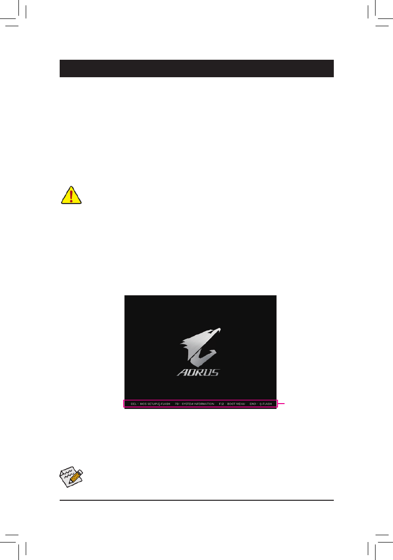
2-1 Startup Screen
The following startup Logo screen will appear when the computer boots.
(Sample BIOS Version: X570 AORUS ELITE, F1a)
Function Keys
•When the system is not stable as usual, select the item to set your system to its defaults.Load Optimized Defaults
•The BIOS Setup menus described in this chapter are for reference only and may differ by BIOS version.
TherearetwodifferentBIOSmodesasfollowsandyoucanusethe<F2>keytoswitchbetweenthetwomodes.
Easy Mode allows users to quickly view their current system information or to make adjustments for optimum
performance.InEasyMode,youcanuseyourmousetomovethroughcongurationitems.TheAdvancedMode
provides detailed BIOS settings. You can press the arrow keys on your keyboard to move among the items
andpress<Enter>toacceptorenterasub-menu.Oryoucanuseyourmousetoselecttheitemyouwant.
- 24 -

2-2 The Main Menu
Advanced Mode Function Keys
<f><g>Move the selection bar to select a setup menu
<h><i> Movetheselectionbartoselectancongurationitemonamenu
<Enter>/DoubleClick Execute command or enter a menu
<+>/<PageUp> Increase the numeric value or make changes
<->/<PageDown> Decreasethenumericvalueormakechanges
<F1> Show descriptions of the function keys
<F2> Switch to Easy Mode
<F3> SavethecurrentBIOSsettingstoaprole
<F4> LoadtheBIOSsettingsfromaprolecreatedbefore
<F5> Restore the previous BIOS settings for the current submenus
<F6> DisplaytheSmartFan5screen
<F7> LoadtheOptimizedBIOSdefaultsettingsforthecurrentsubmenus
<F8> Access the Q-Flash utility
<F10> Save all the changes and exit the BIOS Setup program
<F11> Switch to the Favorites submenu
<F12> Capture the current screen as an image and save it to your USB drive
<Insert> Add or remove a favorite option
<Ctrl>+<S> Displayinformationontheinstalledmemory
<Esc> Main Menu: Exit the BIOS Setup program
Submenus: Exit current submenu
Hardware
Information
OptionDescription Current Settings
Setup Menus
Conguration
Items
System Time
Quick Access Bar allows you to quickly move to
the General Help, Easy Mode, Smart Fan 5, or
Q-Flash screen.
- 25 -

2-3 Favorites (F11)
Setyourfrequentlyusedoptionsasyourfavoritesandusethe<F11>keytoquicklyswitchtothepagewhere
all of your favorite options are located. To add or remove a favorite option, go to its original page and press
<Insert>ontheoption.Theoptionismarkedwithastarsignifsetasa"favorite."
- 26 -

2-4 Tweaker
Whether the system will work stably with the overclock/overvoltage settings you made is dependent on your overall
systemcongurations.Incorrectlydoingoverclock/overvoltagemayresultindamagetoCPU,chipset,ormemory
and reduce the useful life of these components. This page is for advanced users only and we recommend you not to
alter the default settings to prevent system instability or other unexpected results. (Inadequately altering the settings
may result in system's failure to boot. If this occurs, clear the CMOS values and reset the board to default values.)
&CPU Clock Control
AllowsyoutomanuallysettheCPUbaseclockin1MHzincrements.(Default:Auto)
Important: It is highly recommended that the CPU frequency be set in accordance with the CPU
specications.
&CPU Clock Ratio
Allows you to alter the clock ratio for the installed CPU. The adjustable range is dependent on the CPU
being installed.
Advanced CPU Settings
&Core Performance Boost (Note)
Allows you to determine whether to enable the Core Performance Boost (CPB) technology, a CPU
performance-boosttechnology.(Default:Auto)
&SVM Mode
VirtualizationenhancedbyVirtualizationTechnologywillallowaplatformtorunmultipleoperatingsystems
andapplicationsinindependentpartitions.Withvirtualization,onecomputersystemcanfunctionasmultiple
virtualsystems.(Default:Disabled)
&Global C-state Control (Note)
Allows you to determine whether to let the CPU enter C states. When enabled, the CPU core frequency
willbereducedduringsystemhaltstatetodecreasepowerconsumption.(Default:Enabled)
&Power Supply Idle Control (Note)
Enables or disables Package C6 State.
TypicalCurrentIdle Disablesthisfunction.
Low Current Idle Enables this function.
Auto LetstheBIOSautomaticallycongurethissetting.(Default)
&CCD Control (Note)
SetsthenumberofCCDstobeused.(Default:Auto)
(Note) This item is present only when you install a CPU that supports this feature.
- 27 -

&SMT Mode
Allows you to enable or disable the CPU Simultaneous Multi-Threading technology. This feature only works
for operating systems that support multi-processor mode. AutoletstheBIOSautomaticallycongurethis
setting.(Default:Auto)
&AMD CPU fTPM
EnablesordisablestheTPM2.0functionintegratedintheAMDCPU.(Default:Disabled)
&ExtremeMemoryProle(X.M.P.)(Note)
AllowstheBIOStoreadtheSPDdataonXMPmemorymodule(s)toenhancememoryperformancewhen
enabled.
Disabled Disablesthisfunction.(Default)
Prole1 UsesProle1settings.
Prole2(Note) UsesProle2settings.
&XMP High Frequency Support (Note)
Allowsyoutoselectthecompatibilitylevelforhigh-frequencymemory.Thisitemiscongurableonly
when ExtremeMemoryProle(X.M.P.) is set to Prole1 or Prole2.(Default:Auto)
&System Memory Multiplier
Allows you to set the system memory multiplier. AutosetsmemorymultiplieraccordingtomemorySPD
data.(Default:Auto)
Advanced Memory Settings
Memory Subtimings
d Standard Timing Control, Advanced Timing Control, CAD Bus Setup Timing, CAD Bus
DriveStrength,DataBusConguration
These sections provide memory timing settings. Note: Your system may become unstable or fail to boot
after you make changes on the memory timings. If this occurs, please reset the board to default values by
loadingoptimizeddefaultsorclearingtheCMOSvalues.
SPD Info
Displaysinformationontheinstalledmemory.
& CPU Vcore/Dynamic Vcore(DVID)/VCORE SOC/Dynamic VCORE SOC(DVID)/CPU VDD18/
CPU VDDP/PM_1VSOC/PM_1V8/DRAM Voltage (CH A/B)
These items allow you to adjust the CPU Vcore and memory voltages.
Advanced Voltage Settings
ThissubmenuallowsyoutocongureLoad-LineCalibrationlevel,over-voltageprotectionlevel,over-current
protection level, and PWM frequency.
(Note) This item is present only when you install a CPU and a memory module that support this feature.
- 28 -

2-5 Settings
Platform Power
&AC BACK
DeterminesthestateofthesystemafterthereturnofpowerfromanACpowerloss.
Memory The system returns to its last known awake state upon the return of the AC power.
Always On The system is turned on upon the return of the AC power.
AlwaysOff ThesystemstaysoffuponthereturnoftheACpower.(Default)
&ErP
DetermineswhethertoletthesystemconsumeleastpowerinS5(shutdown)state.(Default:Disabled)
Note: When this item is set to , the following functions will become unavailable: Resume by Alarm, Enabled
power on by mouse, and power on by keyboard.
&Soft-Off by PWR-BTTN
ConguresthewaytoturnoffthecomputerinMS-DOSmodeusingthepowerbutton.
Instant-Off Pressthepowerbuttonandthenthesystemwillbeturnedoffinstantly.(Default)
Delay4Sec. Pressandholdthepower buttonfor4 secondstoturn offthesystem.Ifthepower
button is pressed for less than 4 seconds, the system will enter suspend mode.
&Power Loading
Enables or disables dummy load. When the power supply is at low load, a self-protection will activate causing
it to shutdown or fail. If this occurs, please set to Enabled Auto. letstheBIOSautomaticallycongurethis
setting.(Default:Auto)
&Resume by Alarm
Determineswhethertopoweronthesystematadesiredtime.(Default:Disabled)
If enabled, set the date and time as following:
Wakeupday:Turnonthesystemataspecictimeoneachdayoronaspecicdayinamonth.
Wake up hour/minute/second: Set the time at which the system will be powered on automatically.
Note: When using this function, avoid inadequate shutdown from the operating system or removal of the
AC power, or the settings may not be effective.
&Wake on LAN
EnablesordisablesthewakeonLANfunction.(Default:Enabled)
&High Precision Event Timer
EnablesordisablesHighPrecisionEventTimer(HPET)intheoperatingsystem.(Default:Enabled)
- 29 -

IO Ports
&Integrated Graphics (Note)
Enables or disables the onboard graphics function.
Auto The BIOS will automatically enable or disable the onboard graphics depending on the
graphicscardbeinginstalled.(Default)
Forces Enables the onboard graphics.
Disabled Disablestheonboardgraphics.
&UMA Mode (Note)
Specify the UMA mode.
Auto LetstheBIOSautomaticallycongurethissetting.(Default)
UMASpecied SetstheUMAFrameBufferSize.
UMA Auto Sets the display resolution.
ThisitemiscongurableonlywhenIntegrated Graphics Forces is set to .
&UMA Frame Buffer Size (Note)
Framebuffersizeisthetotalamountofsystemmemoryallocatedsolelyfortheonboardgraphicscontroller.
MS-DOS,forexample,willuseonlythismemoryfordisplay.Optionsare:Auto(default),64M~16G.
ThisitemiscongurableonlywhenUMA Mode is set to UMASpecied.
&Display Resolution (Note)
Allows you to set the display resolution. Options are: Auto (default), 1920x1080 and below, 2560x1600,
3840x2160.
ThisitemiscongurableonlywhenUMA Mode is set to UMA Auto.
&Initial Display Output
SpeciestherstinitiationofthemonitordisplayfromtheinstalledPCIExpressgraphicscardortheonboard
graphics.
IGDVideo (Note) Setstheonboardgraphicsastherstdisplay.
PCIe1Slot SetsthegraphicscardonthePCIEX16slotastherstdisplay.(Default)
PCIe2Slot SetsthegraphicscardonthePCIEX4slotastherstdisplay.
&HD Audio Controller
Enablesordisablestheonboardaudiofunction.(Default:Enabled)
If you wish to install a 3rd party add-in audio card instead of using the onboard audio, set this item to
Disabled.
&PCIEX16 Bifurcation
Allows you to determine how the bandwidth of the PCIEX16 slot is divided. Options: Auto, PCIE 2x8,
PCIE1x8/2x4,PCIE4x4.(Default:Auto)
&Above 4G Decoding
Enables or disables 64-bit capable devices to be decoded in above 4 GB address space (only if your system
supports 64-bit PCI decoding). Set to if more than one advanced graphics card are installed and Enabled
their drivers are not able to be launched when entering the operating system (because of the limited 4 GB
memoryaddressspace).(Default:Disabled)
&Onboard LAN Controller
EnablesordisablestheonboardLANfunction.(Default:Enabled)
If you wish to install a 3rd party add-in network card instead of using the onboard LAN, set this item to
Disabled.
(Note) This item is present only when you install a CPU that supports this feature.
- 30 -

USBConguration
&Legacy USB Support
AllowsUSBkeyboard/mousetobeusedinMS-DOS.(Default:Enabled)
&XHCI Hand-off
Determines whether to enable XHCI Hand-offfeature for an operating system without XHCI Hand-off
support.(Default:Enabled)
&USB Mass Storage Driver Support
EnablesordisablessupportforUSBstoragedevices.(Default:Enabled)
&Port 60/64 Emulation
Enables or disables emulation of I/O ports 64h and 60h. This should be enabled for full legacy support
forUSBkeyboards/miceinMS-DOSorinoperatingsystemthatdoesnotnativelysupportUSBdevices.
(Default:Disabled)
&Mass Storage Devices
DisplaysalistofconnectedUSBmassstoragedevices.ThisitemappearsonlywhenaUSBstoragedevice
is installed.
NVMeConguration
DisplaysinformationonyourM.2NVMEPCIeSSDifinstalled.
SATAConguration
&SATA Mode
EnablesordisablesRAIDfortheSATAcontrollersintegratedintheChipsetorcongurestheSATAcontrollers
to AHCI mode.
RAID EnablesRAIDfortheSATAcontroller.
AHCI CongurestheSATAcontrollerstoAHCImode.AdvancedHostControllerInterface
(AHCI)isaninterfacespecicationthatallowsthestoragedrivertoenableadvanced
SerialATAfeaturessuchasNativeCommandQueuingandhotplug.(Default)
&NVMe RAID mode
AllowsyoutodeterminewhethertouseyourM.2NVMePCIeSSDstocongureRAID.(Default:Disabled)
&SATA Port 0/1/2/3/4/5 (SATA3 0, 1, 2, 3, 4, 5 Connectors)
DisplaystheinformationoftheconnectedSATAdevice(s).
`NetworkStackConguration
&Network Stack
DisablesorenablesbootingfromthenetworktoinstallaGPTformatOS,suchasinstallingtheOSfrom
theWindowsDeploymentServicesserver.(Default:Disabled)
&Ipv4 PXE Support
EnablesordisablesIPv4PXESupport.ThisitemiscongurableonlywhenNetwork Stack is enabled.
&Ipv4 HTTP Support
EnablesordisablesHTTPbootsupportforIPv4.ThisitemiscongurableonlywhenNetwork Stack is
enabled.
&Ipv6 PXE Support
EnablesordisablesIPv6PXESupport.ThisitemiscongurableonlywhenNetwork Stack is enabled.
&Ipv6 HTTP Support
EnablesordisablesHTTPbootsupportforIPv6.ThisitemiscongurableonlywhenNetwork Stack is
enabled.
- 31 -

&Case Open
DisplaysthedetectionstatusofthechassisintrusiondetectiondeviceattachedtothemotherboardCI
header.Ifthesystemchassiscoverisremoved,thiseldwillshow"Yes",otherwiseitwillshow"No".To
clear the chassis intrusion status record, set to , save the settings to Reset Case Open Status Enabled
the CMOS, and then restart your system.
&CPU Vcore/CPU VDDP/DRAM Channel A/B Voltage/+3.3V/+5V/+12V/VCORE SOC
Displaysthecurrentsystemvoltages.
Smart Fan 5
&Monitor
Allowsyoutoselectatargettomonitorandtomakefurtheradjustment.(Default:CPUFAN)
&Fan Speed Control
Allows you to determine whether to enable the fan speed control function and adjust the fan speed.
Normal Allows the fan to run at different speeds according to the temperature. You can adjust
the fan speed with System Information Viewer based on your system requirements.
(Default)
Silent Allows the fan to run at slow speeds.
Manual Allows you to control the fan speed in the curve graph.
Full Speed Allows the fan to run at full speeds.
&Fan Control Use Temperature Input
Allows you to select the reference temperature for fan speed control.
&Temperature Interval
Allows you to select the temperature interval for fan speed change.
&Fan Control Mode
Auto Lets the BIOS automatically detect the type of fan installed and sets the optimal control
mode.(Default)
Voltage Voltage mode is recommended for a 3-pin fan.
PWM PWM mode is recommended for a 4-pin fan.
&Fan Stop
Enables or disables the fan stop function. You can set the temperature limit using the temperature curve.
Thefanstopsoperationwhenthetemperatureislowerthanthelimit.(Default:Disabled)
&Temperature
Displaysthecurrenttemperatureoftheselectedtargetarea.
&Fan Speed
Displayscurrentfanspeeds.
&Flow Rate
Displaystheowrateofyourwatercoolingsystem.
&Temperature Warning
Sets the warning threshold for temperature. When temperature exceeds the threshold, BIOS will emit
warningsound.Optionsare:Disabled(default),60oC/140oF, 70oC/158oF, 80oC/176oF, 90oC/194oF.
&Fan Fail Warning
Allows the system to emit warning sound if the fan is not connected or fails. Check the fan condition or fan
connectionwhenthisoccurs.(Default:Disabled)
- 33 -
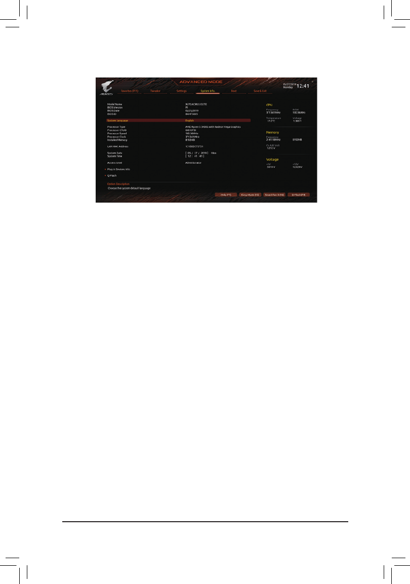
2-6 System Info.
This section provides information on your motherboard model and BIOS version. You can also select the default
language used by the BIOS and manually set the system time.
&System Language
Selects the default language used by the BIOS.
&System Date
Setsthesystemdate.Thedateformatisweek(read-only),month,date,andyear.Use<Enter>toswitch
betweentheMonth,Date,andYeareldsandusethe<PageUp>or<PageDown>keytosetthedesired
value.
&System Time
Sets the system time. The time format is hour, minute, and second. For example, 1 p.m. is 13:00:00. Use
<Enter>toswitchbetweentheHour,Minute,andSecondeldsandusethe<PageUp>or<PageDown>
key to set the desired value.
&Access Level
Displaysthecurrentaccessleveldependingonthetypeofpasswordprotectionused.(Ifnopasswordis
set, the default will display as .) The Administrator level allows you to make changes to all Administrator
BIOS settings; the User level only allows you to make changes to certain BIOS settings but not all.
Plug in Devices Info
DisplaysinformationonyourSATA,PCIExpress,andM.2devicesifinstalled.
Q-Flash
AllowsyoutoaccesstheQ-FlashutilitytoupdatetheBIOSorbackupthecurrentBIOSconguration.
- 34 -
Produktspezifikationen
| Marke: | Gigabyte |
| Kategorie: | Hauptplatine |
| Modell: | X570 Aorus Elite Wifi |
| Prozessorhersteller: | AMD |
| WLAN: | Ja |
| WLAN-Standards: | 802.11a, 802.11b, 802.11g, Wi-Fi 4 (802.11n), Wi-Fi 5 (802.11ac) |
| Bluetooth: | Ja |
| Bluetooth-Version: | 4.2 |
| Breite: | 305 mm |
| Tiefe: | 244 mm |
| Energiequelle: | ATX |
| Kopfhörerausgänge: | 1 |
| Anzahl USB 2.0 Anschlüsse: | 4 |
| Anzahl Ethernet-LAN-Anschlüsse (RJ-45): | 1 |
| Anzahl HDMI-Anschlüsse: | 1 |
| Audio Kanäle: | 5.1 Kanäle |
| Unterstützt Windows-Betriebssysteme: | Windows 10 Education x64, Windows 10 Enterprise x64, Windows 10 Home x64, Windows 10 Pro x64, Windows 10 x64 |
| HDCP: | Ja |
| Mikrofon-Eingang: | Ja |
| Unterstützte Speicherlaufwerke: | HDD & SSD |
| RAID Level: | 0, 1,10 |
| USB 3.2 Gen 1 (3.1 Gen 1) Anzahl der Anschlüsse vom Typ A: | 4 |
| Prozessorsockel: | Socket AM4 |
| Kompatible Prozessoren: | AMD Ryzen 3 2nd Gen, AMD Ryzen 3 3rd Gen, AMD Ryzen 5 2nd Gen, AMD Ryzen 5 3rd Gen, AMD Ryzen 7 2nd Gen, AMD Ryzen 7 3rd Gen, AMD Ryzen 9 3rd Gen |
| Maximale Anzahl an SMP-Prozessoren: | 1 |
| Motherboardformfaktor: | ATX |
| Motherboard Chipsatz Familie: | AMD |
| Motherboard Chipsatz: | AMD X570 |
| Audio-Chip: | Realtek ALC1200 |
| Komponente für: | PC |
| Unterstützte Arbeitsspeicher: | DDR4-SDRAM |
| Anzahl der Speichersteckplätze: | 4 |
| Arbeitsspeicher Typ: | DIMM |
| Speicherkanäle: | Zweikanalig |
| ECC: | Ja |
| Ohne ECC: | Ja |
| Unterstützte Arbeitsspeichergeschwindigkeit: | 2133,2400,2667,2933,3200,3300,3333,3400,3466,3600,3733,3800,3866,4000 MHz |
| RAM-Speicher maximal: | 128 GB |
| Unterstützte Speicherlaufwerk-Schnittstellen: | M.2, SATA III |
| Anzahl der M.2 (M)-Steckplätze: | 2 |
| PCI-Express x16 (Gen 3.x)-Anschlüsse: | 1 |
| Maximaler Grafikkartenspeicher: | 16384 MB |
| Maximale Auflösung: | 4096 x 2160 Pixel |
| Parallele Verarbeitungstechnologie: | 2-Way CrossFireX, Quad-GPU CrossFireX |
| Treiber enthalten: | Ja |
| ATX Stromstecker (24-pol.): | Ja |
| SATA III Anschlüsse: | 6 |
| Anzahl USB 2.0 Schnittstellen: | 2 |
| CPU Ventilatorstecker: | Ja |
| Zahl der Chassisventilatorstecker: | 2 |
| Front Panel Audiostecker: | Ja |
| Frontpanel-Stecker: | Ja |
| TPM-Verbinder: | Ja |
| RGB-LED-Stiftleiste: | Ja |
| USB 3.2 Gen 1 (3.1 Gen 1) Anschlüsse: | 2 |
| Clear CMOS-Jumper: | Ja |
| BIOS-Speichergröße: | 128 Mbit |
| BIOS-Typ: | UEFI AMI |
| ACPI-Version: | 5.0 |
| Systemverwaltung BIOS (SMBIOS) Version: | 2.7 |
| Ethernet Schnittstellen Typ: | Gigabit Ethernet |
| Mitgelieferte Software: | Norton Internet Security (OEM version)\ncFosSpeed |
| USB 3.2 Gen 2 (3.1 Gen 2) Anzahl der Anschlüsse vom Typ A: | 2 |
| HDD Größe: | 2.5/3.5 " |
| S/PDIF-Ausgang: | Ja |
| Unbuffered Speicher: | Ja |
| Diskreter Grafik support: | Ja |
| Intel® Extreme Memory Profile (XMP): | Ja |
| Power Fan Connector: | Ja |
| Unterstützte Prozessorsteckplätze: | Socket AM4 |
| Kühlung: | Aktiv |
| EPS Stromstecker (8-pin): | Ja |
| Desktop Management Interface (DMI) Version: | 2.7 |
| Unterstützte Speichermodulkapazitäten: | 4GB, 8GB, 16GB, 32GB |
| WiFi-AP-Antennenbuchse: | 2 |
| USB 3.2 Gen 2 (3.1 Gen 2) Anschlüsse: | 1 |
| PCI Express x16-Steckplätze (Gen 4.x): | 1 |
| Nebenkosten inklusive: | Ja |
| Ethernet/LAN: | Ja |
Brauchst du Hilfe?
Wenn Sie Hilfe mit Gigabyte X570 Aorus Elite Wifi benötigen, stellen Sie unten eine Frage und andere Benutzer werden Ihnen antworten
Bedienungsanleitung Hauptplatine Gigabyte

7 Oktober 2024
5 Oktober 2024
24 September 2024
17 September 2024
16 September 2024
15 September 2024
13 September 2024
11 September 2024
10 September 2024
9 September 2024
Bedienungsanleitung Hauptplatine
- Hauptplatine Asus
- Hauptplatine Sharkoon
- Hauptplatine MSI
- Hauptplatine Supermicro
- Hauptplatine NZXT
- Hauptplatine Asrock
- Hauptplatine ECS
- Hauptplatine EPoX
- Hauptplatine Evga
- Hauptplatine Intel
- Hauptplatine Abit
- Hauptplatine Elitegroup
- Hauptplatine Foxconn
- Hauptplatine Biostar
Neueste Bedienungsanleitung für -Kategorien-

15 Oktober 2024
4 Oktober 2024
4 Oktober 2024
2 Oktober 2024

27 September 2024
26 September 2024
22 September 2024
22 September 2024
19 September 2024
17 September 2024