GeoVision UA-R580F2 Bedienungsanleitung
GeoVision
Überwachungskamera
UA-R580F2
Lesen Sie kostenlos die 📖 deutsche Bedienungsanleitung für GeoVision UA-R580F2 (62 Seiten) in der Kategorie Überwachungskamera. Dieser Bedienungsanleitung war für 26 Personen hilfreich und wurde von 2 Benutzern mit durchschnittlich 4.5 Sternen bewertet
Seite 1/62
Before attempting to connect or operate this product,
please read these instructions carefully and save this manual for future use.
IP Cameras
UVSCAM-UM-C
UA-B580F3
UA-R500F2
UA-R560F2
UA-R580F2
UA-R800F2

© 2022 USAVision, Inc. All rights reserved.
Under the copyright laws, this manual may not be copied, in whole or in part, without
the written consent of USAVision.
Every effort has been made to ensure that the information in this manual is accurate.
USAVision makes no expressed or implied warranty of any kind and assumes no
responsibility for errors or omissions. No liability is assumed for incidental or
consequential damages arising from the use of the information or products contained
herein. Features and specifications are subject to change without notice.
USA Vision Systems Inc.
9301 Irvine Blvd,
Irvine, CA 92618, USA
Tel: +1-949-421-5910
Fax: +1-949-583-152
https://www.geovision.com.tw/us/
June 2022
Scan the following QR codes for product warranty and technical support policy:
[Warranty] [Technical Support Policy]

Contents
Introduction .......................................................................................................................... 1
1. Overview .......................................................................................................................... 1
1.1 Range of Application 1..............................................................................................
1.2 Product Description ................................................................................................ 2
1.3 Operation Environment .......................................................................................... 2
1.4 Camera Overview ................................................................................................... 3
1.4.1 UA-R500F2 / UA-R560F2 / UA-R580F2 / UA-R800F2 ............................... 3
1.4.2 UA-B580F3 4...................................................................................................
2. Device Connection ........................................................................................................... 5
3. Setting IP address via Device Cong Tool 6......................................................................
4. IE Log in ........................................................................................................................... 8
4.1 Access to IPC web port .......................................................................................... 8
4.2 Initial login ............................................................................................................... 9
4.3 General login ........................................................................................................ 11
4.4 Retrieve password ................................................................................................ 12
4.4.1 Security Question Verication ........................................................................... 12
4.4.2 Key File .............................................................................................................. 13
4.4.3 Super Password ................................................................................................ 14
4.5 Password Expired . ................................................................................................ 14
5. Plug-in Installation ......................................................................................................... 16
6. Preview .......................................................................................................................... 17
6.1 Live ....................................................................................................................... 17
6.2 Recording Status .................................................................................................. 19
7. Playback ........................................................................................................................ 20
7.1 General Playback ................................................................................................. 20
7.2 Playback Searched by Human & Vehicle Detection ............................................ 22
7.3 PID&LCD .............................................................................................................. 23
8. Remote Setting .............................................................................................................. 24
8.1 Live ....................................................................................................................... 24
8.2 Image Control ....................................................................................................... 25
8.3 Video Cover .......................................................................................................... 28
8.4 ROI ....................................................................................................................... 29
8.5 Record .................................................................................................................. 30
8.5.1 Encode ....................................................................................................... 30
8.5.2 Record ........................................................................................................ 31
8.6 Event ..................................................................................................................... 33
8.6.1 Setup .......................................................................................................... 33
8.6.2 Alarm .......................................................................................................... 35
8.7 AI ........................................................................................................................... 38
8.7.1 Setup .......................................................................................................... 38
8.7.2 Alarm .......................................................................................................... 56
8.7.3 Statistics ..................................................................................................... 58

8.8 Network................................................................................................................. 61
8.8.1 General ....................................................................................................... 61
8.8.2 Email (Email Conguration) ....................................................................... 65
8.8.3 FTP ............................................................................................................. 66
8.8.4 RTSP .......................................................................................................... 67
8.8.5 DDNS ......................................................................................................... 68
8.8.6 HTTPS ........................................................................................................ 69
8.8.7 IP Filter ....................................................................................................... 70
8.9 Device ................................................................................................................... 71
8.9.1 Disk ............................................................................................................71
8.9.2 Audio .......................................................................................................... 71
8.9.3 Cloud .......................................................................................................... 72
8.10 System ................................................................................................................ 73
8.10.1 General ..................................................................................................... 73
8.10.2 Multi-User ................................................................................................. 75
8.10.3 Maintenance ............................................................................................. 78
8.10.4 Information ............................................................................................... 82
9. Local Settings ................................................................................................................ 83

Introduction
Thank you for using our network camera products. Our network camera products are
integrated and developed for network video monitoring igh-performance single SOC . H
chips are used in media processor for audio/video acquisition, compression and
transmission/transfer. Standard H.264/H.265 encoding algorithm is applied to ensure
clear and smooth video representation and transfer performance. Embedded Web Server
oers users access to real-time surveillance and remote control of front-end camera
throug web browser. h
The network cameras are easy to install and operate. The network cameras are
applicable to large and medium-size enterprises, governmental projects, large mall, chain
supermarkets, intelligent buildings, hotels, Hospitals and schools and other group
customers, as well as to applications requiring remote network video transmission and
monitoring.
Instructions:
⚫ For purpose of this manual, IP camera means network camera.
⚫ Single click means a single click on the left mouse button.
⚫ Double click means a double-click on the left mouse button.
⚫ The default factory IP address for IP camera is 192.168.1.168.
⚫ The default administrator username for IP camera is (in lowercase), and there admin
is no default password.
⚫ The default Web port number is 8 the default media port number is 9 The 0 d an 000.
ONVIF port number is synchronized with the web port number.
Statement:
Some information contained in this manual may dier from the actual product. For any
problems you cannot solve with the use of this manu , please contact our technical al
support or the authorized dealers. This manual may be subject change without prior to
notice.
CAUTION
RISK OF EXPLOSION IF BATTERY IS REPLACED BY AN INCORRECT TYPE
DISPOSE OF USED BATTERIES ACCORDING TO THE INSTRUCTIONS

1
1. Overview
1.1 Range of Application
The network cameras with powerful image processing capacity may be applied at various
public places such as mall, supermarket, school, factory and workshop, as well as in
environments requiring HD video image such as ba and trac control system, as shown nk
below:

2
1.2 Product Description
An IP camera is a digital online surveillance camera embedded with Web server and
capable of independent operation, giving user access to real-time monitoring through web
browser or client software from any place across the world.
IP camera is based on the latest digital solution, an integrated media processing platform
for audio/video acquisition, compression and network transmission on a single board. It is
in compliance with H 64/ H265 High Prole encoding standards. Any remote user can .2
have access to real-time monitoring by entering the IP address or domain name of the IP
camera in web browser. This network camera solution is applicable to residential or
business environments as well as a wide range of situations requiring remote network
video monitoring and transmission. The IP camera products are easy to install and
operate.
The IP cameras can be managed by several users with dierent authorization levels.
IP cameras all s mobile detection, and sends e-ow mail and snapshot taken in case of
emergency and store the image or video snapshot in SD card for retrieval.
1.3 Operation Environment
Operating system: Windows 7/Windows 8/Windows 2008 (32/64-bit),
Windows 2003/Windows XP/Windows 2000 (32-bit)
CPU: Intel Core Duo II dual-core processor or higher
Memory: 1G or more Video memory: 256M or more
Display: 1024 × 768 or higher resolution
IE: IE or higher version 10

3
1.4 Camera Overview
1.4.1 -R500F2 / UA-R560F2 / UA-R580 / UA-R800F2 UA F2
1
2
4
3
4
5
67
N o.
Description
N o.
Descripti on
1
IR LED x 2 (For UA-R500F2 / R560F2 /
R800F2)
5
Warm LED x 2 (For UA-R580F2)
2
Built- microphone (For in UA-R500F2 /
R560F2 / R800F2)
6
Default button
3
IR LED x 2 (For UA-R580F2)
7
SD card slot
4
B - microphone (For uilt in UA-R580F2)
Note: Press the default button fo 15 seconds to reboot the camera. r
4
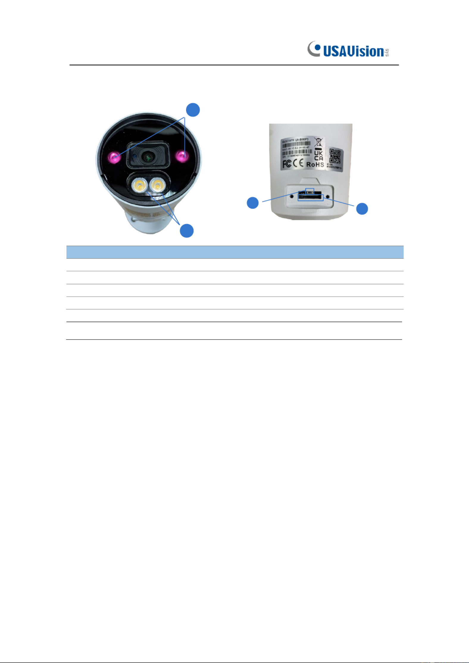
1.4.2 -B580F3 UA
4
1
2
4
34
N o.
Description
1
IR LED x 2
2
Warm LED x 2
3
Default button
4
SD card slot
Note: Press the default button fo 15 seconds to reboot the camera. r

5
2. Device Connection
IP camera can be connected in two ways:
1. Connection to PC
Connect IP camera to PC via straight- rough network cable, with power input connected th
to a DC 12V adaptor, and set the IP addresses of the PC and IP camera in one network
segment. The IP camera will communicate with PC within one minute after being powered
on if the network operates normally.
2. Connection to router/switch
This is more commonly used in connecting the IP camera to Internet, where the camera
and PC are connected to LAN ports of a router/switch, with gateway of the camera set to
the IP address of the router.

6
3 Setting IP address via Device Cong Tool .
Devices that communicate with each other on the Internet must follow the constraints of
the network protocol. For example, the PC and IPC are in the same local area network,
a the setting IP of the IPC must be in the same network segment as the IP of the PC in nd
order to communicate normally. Take the camera in factory mode as an example:
Step 1: Obtain the basic setting information of the current network. Open Network on the
PC (Win10) Open Network and Internet Settings→ →Network Sharing Center Ethernet→ →
Details to view the setting information of the current network.
Note: If the current network supports DHCP to assign IP, this step can be ignored.

7
Step 2: Run Device Utility and click ch to get the IPC information as shown in Sear
Figure 3.1. The IPC can be located according to the P2P ID or Mac address.
Figure 3.1
Note: The default IP of the camera is 192.168.1.168 the default account is admin. , and
Step 3: As shown in Figure 3.1, select the corresponding device, enter the account and
password, edit the corresponding network information, and click Modify to save the
information.
Note: If the current network supports DHCP to distribute network, change Network Mode
to DHCP to obtain IP.

8
4 IE Log . in
4.1 Access to IPC web port
Use Device Utility to search the IPC o e current network. Click on the searched IP and f th
log in to the camera with web browser as shown in Figure 4.1.1.
Figure 4.1.1
You can also directly open the web browser and enter ://ip:web port. ke device http Ta
shown in Figure 4.1.1 as example, e IP of the current device to be accessed is an th
192.168.5.218 he web port is 80, and the combined URL is , t http://192.168.5.2 :8018 .
Note: In actual use scenario, the http access method will default to port 80.

9
4.2 Initial login
In the rst time accessing the web of the camera, the program will remind you to set a
more complicated password as the default password of the device is too simple. The
interface as shown in Figure 4.2.1 will be popped up. Click to check password
requirements:
The password should be 8-15 characters, including letters, numbers or special characters.
1. 8~9 characters: The combination should consist of at least 3 uppercase letters,
lowercase letters, numbers or special characters.
2. 10~15 characters: The combination should consist of at least 2 uppercase letters,
lowercase letters, numbers or special characters.
3. It is forbidden to repeat and continuous characters exceeding 4 digits.
4. It is forbidden for the continuous keys of the keyboard pattern to exceed 4 digits.
Figure 4.2.1
10
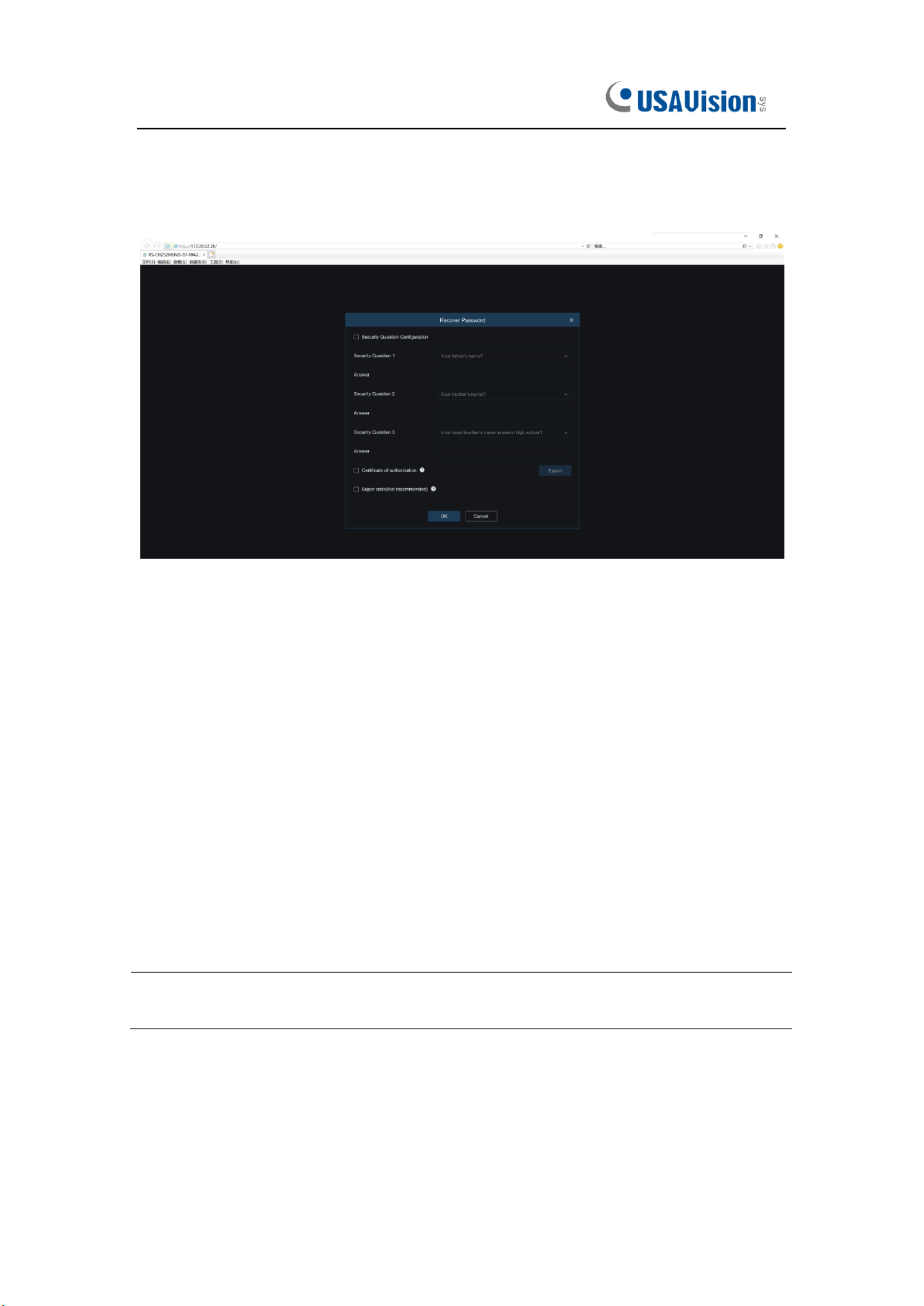
Set a new password, click OK to save, the interface as shown in Figure 4.2.2 will pop up.
You can check to c ose the corresponding password retrieval method, or cancel the ho
setting directly without checking, and the password retrieval function will not be enabled.
Figure 4.2.2
①Security Question Conguration: To modify the main user s password by question ’
verication. After enabling, you need to select 3 of the 15 frequently used questions and
set the answer required to retrieve the password. The maximum length of the answer is 64
characters.
②Certicate of authorization: To modify the main user's password by key. After it is
enabled, you need to click Export to download the key le namely certicate.txt.
③Super code (Not recommended): Use the super verication code to modify the main
user’s password. A super verication code can be calculated by current camera's Mac
address and the camera system time to modify the main user's password. However, the
camera's Mac is broadcast on the network, and the camera system time can be obtained
directly when logging in to the Web and using Super code to modify the master user
password. There are certain security risks, so it is not recommended for users to turn it on.
Note: When enabling the password retrieval function, please keep the verication
information properly.

11
4.3 General login
To access the came web interface, the login interface will be entered as shown in Figure ra
4.3.1. Enter the corresponding account password, then click login, you can access the
camera's operating interface. At the same time, you can select the desired language when
log in.
Figure 4.3.1

12
4.4 Retrieve password
When you forget the login information, you can click Recover Password on the login
interface to enter the password retrieval interface. According to the rst login settings, it
supports three modes: security question verication, key file, and super password.
4.4.1 Security Question Verication
Reset the main user password through the security question and open the password
retrieval interface. As shown in Figure 4.4.1, the default interface is to retrieve the
password through the problem verication. Fill in the corresponding answer in the security
question, you can directly modify the password of the current main user.
Figure 4.4.1

13
4.4.2 Key File
When set up the password authentication questions in initial login, you can turn on the key
search and modify password function and prompt to download the key le certicate.txt.
Open the password retrieval interface, switch to the Certicate of authorization mode, and
the interface is converted as shown in Figure 4.4.2. Click Import to select the key le
certicate.txt. After the Import is successful, enter the new password to modify the main
user’s password.
Figure 4.4.2

15
When user decides to change the password, the interface jumps to Figure 4.5.1.
According to e interface prompts, user can set a new password by verification with old th
password.
Figure 4.5.1

16
5 Plug-i Installation. n
Use IE browser to log in, you need to install the plug-in to preview the image normally.
When the prompt in Figure 5.1.1 appears, please download and install the plug-in
according to the prompt.
Figure 5.1.1
Note: Programs without plug-ins are supported. When using Safari 12 or later, Chrome 57
or later, Firefox 52 or later, Edge 41 and other browsers for web access, the plug-in
ins llation steps can be ignored. ta

19
6.2 Recording Status
The recording status is a simple reminder from the web to the curr alarm of the cameraent ,
which can show whether the recording is normal. There can be multiple alarms at the
same time. For specic instructions, please refer to the following introduction:
No icon: The SD card of camera is normal, but no video is being recorded.
: The camera is performing general recordi ng.
Note: When the camera performs alarm recording, the mark will disappear, but general
recording will continue.
: The SD card is in an abnormal state, please check the SD card.
: The camera is in motion alarm, but motion alarm recording is not enabled.
: The camera is in motion alarm, and motion alarm recording is performing.
: The camera is in smart alarm, but the smart alarm recording is not performed.
Note: Intelligent alarms include Human & hicle alarm, etc. Ve
: The camera is in smart alarm and smart alarm recordi is performing.ng

20
7 Playback .
The camera not only needs to allow us to see the real- me image, but also needs to save ti
the image information so that it can be retrieved and viewed en needed. wh
7.1 General Playback
The playback function is mainly composed of General cture / Tag / AI search functions. / Pi
The following gure shows the video search.
Search Mode: Switch the current search mode. As shown in the gure above, the default
is General search, and the search information is ordinary video les. You can switch to
Picture / Tag / AI search. (Picture search not applicable to - 00F2 / R800F2 while is UA R5
AI search is not applicable to UA-R500F2 .)
Date: Set the date to search for the video, click search, it will prompt the date of the video
le.
Search Type: Display the search type supported by the camera. You can search and view
part of the video according to your dema nd.
Search: Search and display the videos in the SD card according to the search settings.
Pause/Play:
:
:
::Pause/Play playback stream
Stop:
:
:
::Close the playback stream
21
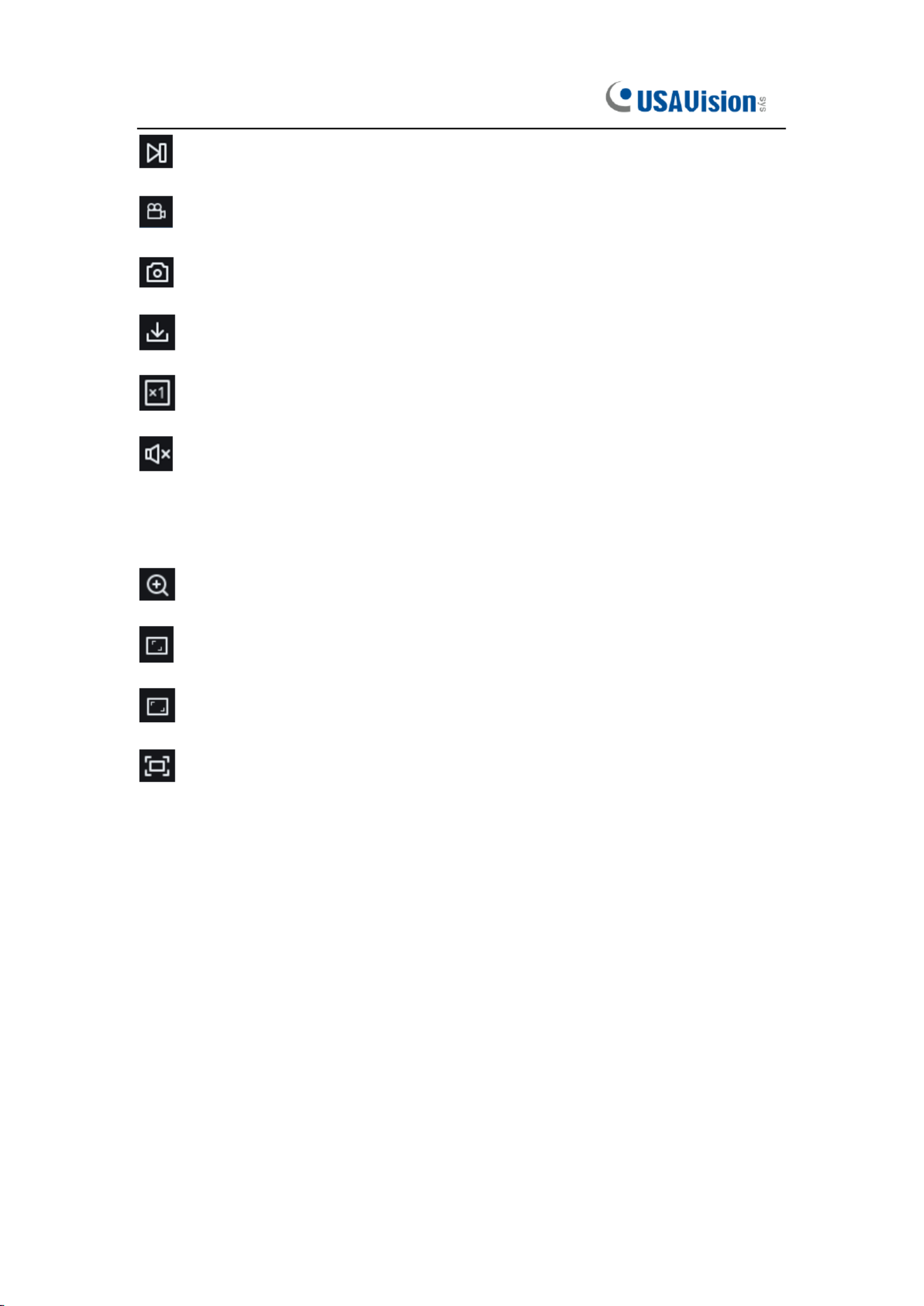
Forward by One Frame:
:
:
::Play one frame of image every time you click
Record:
:
:
::Manually record the current preview stream
Capture:
:
:
::Manually capture the picture of the current stream
Download:
:
:
::Download the currently searched video
speed:
:
:
::Playing speed. Support speed adjustment like 1/8, 1/4, 1/2, 1, X2, X4, X8
Audio:
:
:
::Turn on/off, adjust the sound of playback stream
Playback progress bar: The time bar below shows the current playback progress bar in
dierent colors according to the search results.
Digital Zoom:
:
:
::El ronically zoom in certain area of the display streamect on
Original Proportions:
:
:
::Display the current preview image in original proportions
Stretch:
:
:
::Display the current preview image in a way that lls the display area
Full Screen:
:
:
::Display the current preview image in full screen, you can double-click
the screen to turn on/off the function, and press Esc to exit the full screen when enabling
the function
Playback progress bar zoom in/out: The progress bar defaults to display the progress
of 24 hours. By this functi , you can more accurately jump to the corresponding playback on
position. This function also works through the mouse wheel.

23
7.3 PID&LCD
With the development of technology, AI-PID&LCD is added human & vehicle detection
function, can alarm the target of human & vehicle only. Besides, the picture or video is
recorded, which is easy to search and view. The interface is shown in the gure below.
Search Mode:
:
:
::Switch the search mode. The current search mode is AI-PID&LCD.
Start time:
:
:
::Set the start time of search.
End time:
:
:
::Set t end time of search. he
Vigilance:
:
:
::Set the capture mode of triggering the alarm to PID or LCD, and it can also be
set at the same time.
Detection Type:
:
:
::Set the captures of human or car to be searched, and you can also
search both at the same time.
Search:
:
:
::Search for human & car captures according to the search element settings.
Search Results Display Area:
:
:
::Display the search results. Double-click the picture to
enter the playback for a short period of time before and after the detection.
Search results Flip:
:
:
::You can ip the search results in the lower right corner.

24
8 Remote Setting .
8.1 Live
The Live is to set the location where the channel name, device time, CC and other
intelligent function statistics data and the image are superimposed. The interface is shown
in the gure below.
Name:
:
:
::Set the channel name that camera shown on the OSD.
Date Format: Set OSD date format displaying. There are three types: MM/DD/YYYY,
YYYY- -DD, and DD/MM/YYYY. MM
Time Format:
:
:
::Set OSD time format. There are 12 hours and 24 hours optional.
Flicker Control:
:
:
::Set the refresh rate of the image. There are two options of 60Hz and
50Hz, corresponding to N standard and P standard.
Show Name:
:
:
::Set whether to display the channel name in the image.
Show Time:
:
:
::Set whether to show the channel time in the image.
Channel Name Display Position:
:
:
::Set by dragging the channel name on the image.
Time Display Position: Set by dragging the channel time on the image.
Alarm Statistics Display Position: Set by dragging the position of the channel alarm
statistics on the image. This setting will only be displayed when the function is enabled.

25
Save:
:
:
::Save current modication.
Refresh:
:
:
::Re-obtain the current interface parameters.
8.2 Image Control
Image control is to directly control and modify graphics parameters, such as color to black
mode wide dynamic, backlight supplement, etc. The interface is shown below. , as
IR-CUT Mode:
:
:
::Set the day/night switching mode of the camera, a total of 5 modes. Note
that this is only applicable to UA-R500F2 / R560F2 / R800F2.
Automatic mode: Automatically control switching mode. Color switching to black white is
controlled by image, black white switching to color is controlled by photosensitive.
Color Mode: Mandatory color mode, do not switch to black white mode.
Black White Mode: Mandatory black white mode, do not switch to color mode.
Image Mode: Similar to the automatic mode, the color- -black and the black- -color to to
modes are controlled through the image (supported some models) by
Schedule: Switch between black white and color through the schedule setting. To enable
this function, you need to set the start and end time of night vision.
IR-CUT Delay:
:
:
::Automatic mode and Image Mode switch between day and night the ,
duration of IR-CUT need to be determined. For example, when switching the night vision,
the night vision switch will only be performed when the camera is in the dark for the set
time. Note that this is only applicable to UA-R500F2 / R560F2 / R800F2.

26
IR-LED:
:
:
::Set the ll light effect of the camera's IR LED during night vision, there are 2
modes. Note that this is only applicable to UA-R500F2 / R560 / R800F2. F2
SmartIR:
:
:
::Intelligently control the intensity of the IR LED's ll light, and dynamically control
the IR LED's fill light according to the focal length and whether the picture is
over-exploded.
Manual:
:
:
::Manual mode, fill light with the set brightness of the IR LED.
Angle Trad:
:
:
::Image rotation setting. The camera is inverted from the preset in some
scenarios. For example, it is designed to be used upside down, but in practice it is used
horizontally. The image can be adjusted by this value.
Mirror:
:
:
::Set the mirror mode to adjust the picture effect, there are 4 modes.
Disable: Turn off the mirror mode.
Vertical:
:
:
::Mirror mode in vertical direction, which makes the images of the screen
interactive up and down.
Horizontal:
:
:
::Mirror mode in horizontal direction, which makes images of the screen
interactive left and right.
All:
:
:
::Turn on Vertical and Horizontal at the same time, the effect is similar to 180° rotation,
but the realization principle is different.
Backlight:
:
:
::Set the performance of the rmware in backlight, there are 4 modes:
WDR:
:
:
::Wide dynamic mode, according to the set value to make the overall picture in a
balanced state, bright and k areas can be seen clearly. dar
HLC:
:
:
::Highlight Compensation. Make the objects in the highlighted area clearer in the
image. (Supported by some models)
Back Light:
:
:
::Make objects clearer in dark places.
Disable:
:
:
::Turn off Back Light.
White Balance:
:
:
::Use three primary colors of red, green, and blue to generate white after
mixing, which is an indicator of color adjustment. There are 2 modes.
Automatic mode: Use the default parameters of the rmware to adjust the white light.
Manual: The user actively sets the red, gr , and blue gains to synthesize white light. een

27
Shutter:
:
:
::Set the shutter exposure time, there are 2 modes.
Automatic mode: According to the set Time Exposure value, the rmware automatically
selects an appropriate exposure time.
Manual: Directly use the time set in Time Exposure.
Time Exposure:
:
:
::Set the camera's exposure time, used in conjunction with Shutter. When
the exposure time is long, the image will be overexposed, and when the exposure time is
short, the picture will be dark.
3D Noise Reduction:
:
:
::Reduce the noise in the image and make the picture clearer. There
are three modes:
Automatic mode: The camera automatically selects the noise reduction according to the
algorithm.
OFF:
:
:
::Disable noise reduction.
Manual: Reduce noise manually.
Save:
:
:
::Save parameters.
Default:
:
:
::Restore parameters to the default.
Refresh:
:
:
::Re-obtain parameters.

28
8.3 Video Cover
In actual use, some areas are not suitable for monitoring and recording. Those areas can
be hidden in the video through this function. The interface is shown in the gure below.
Enable:
:
:
::Switch to turn on the function.
Cover Area:
:
:
::Set the area that needs to be covered on the monitoring screen. When
setting, the covering block is red, and the corresponding area of the screen is black when
it is enabled. 4 covering blocks can be set.
Delete:
:
:
::Remove the selected covering block.
Produktspezifikationen
| Marke: | GeoVision |
| Kategorie: | Überwachungskamera |
| Modell: | UA-R580F2 |
Brauchst du Hilfe?
Wenn Sie Hilfe mit GeoVision UA-R580F2 benötigen, stellen Sie unten eine Frage und andere Benutzer werden Ihnen antworten
Bedienungsanleitung Überwachungskamera GeoVision

28 August 2024
28 August 2024
28 August 2024
28 August 2024
28 August 2024
28 August 2024
28 August 2024
28 August 2024
28 August 2024
28 August 2024
Bedienungsanleitung Überwachungskamera
- Überwachungskamera Samsung
- Überwachungskamera Approx
- Überwachungskamera Belkin
- Überwachungskamera Sanyo
- Überwachungskamera Exibel
- Überwachungskamera Gembird
- Überwachungskamera Genius
- Überwachungskamera Hama
- Überwachungskamera LogiLink
- Überwachungskamera Logitech
- Überwachungskamera Manhattan
- Überwachungskamera Nedis
- Überwachungskamera Niceboy
- Überwachungskamera Philips
- Überwachungskamera Sony
- Überwachungskamera Trust
- Überwachungskamera Panasonic
- Überwachungskamera Clas Ohlson
- Überwachungskamera Profile
- Überwachungskamera ZyXEL
- Überwachungskamera Bosch
- Überwachungskamera Laserliner
- Überwachungskamera Buffalo
- Überwachungskamera Canon
- Überwachungskamera Velleman
- Überwachungskamera Powerfix
- Überwachungskamera Eminent
- Überwachungskamera Linksys
- Überwachungskamera Maginon
- Überwachungskamera Netgear
- Überwachungskamera Technaxx
- Überwachungskamera Alecto
- Überwachungskamera Denver
- Überwachungskamera EMOS
- Überwachungskamera Gira
- Überwachungskamera König
- Überwachungskamera MarQuant
- Überwachungskamera Renkforce
- Überwachungskamera Thomson
- Überwachungskamera Trevi
- Überwachungskamera Blaupunkt
- Überwachungskamera Schneider
- Überwachungskamera Trebs
- Überwachungskamera Pyle
- Überwachungskamera Topcom
- Überwachungskamera Pioneer
- Überwachungskamera JVC
- Überwachungskamera Motorola
- Überwachungskamera Xiaomi
- Überwachungskamera Abus
- Überwachungskamera Avidsen
- Überwachungskamera Elro
- Überwachungskamera EZVIZ
- Überwachungskamera Imou
- Überwachungskamera INSTAR
- Überwachungskamera Megasat
- Überwachungskamera Olympia
- Überwachungskamera Smartwares
- Überwachungskamera Switel
- Überwachungskamera Yale
- Überwachungskamera Ferguson
- Überwachungskamera Orion
- Überwachungskamera Gigaset
- Überwachungskamera Strong
- Überwachungskamera Toshiba
- Überwachungskamera Garmin
- Überwachungskamera Perel
- Überwachungskamera Netis
- Überwachungskamera Lindy
- Überwachungskamera Fenton
- Überwachungskamera Waeco
- Überwachungskamera Acme
- Überwachungskamera Burg Wächter
- Überwachungskamera Marmitek
- Überwachungskamera Marshall
- Überwachungskamera Honeywell
- Überwachungskamera B/R/K
- Überwachungskamera Marshall Electronics
- Überwachungskamera TRENDnet
- Überwachungskamera Targa
- Überwachungskamera First Alert
- Überwachungskamera AVerMedia
- Überwachungskamera Zebra
- Überwachungskamera TP-Link
- Überwachungskamera Flamingo
- Überwachungskamera Kodak
- Überwachungskamera Rollei
- Überwachungskamera IGet
- Überwachungskamera Adj
- Überwachungskamera Netatmo
- Überwachungskamera Duramaxx
- Überwachungskamera Ebode
- Überwachungskamera Xavax
- Überwachungskamera InFocus
- Überwachungskamera Overmax
- Überwachungskamera Monoprice
- Überwachungskamera Monacor
- Überwachungskamera JUNG
- Überwachungskamera Ednet
- Überwachungskamera AG Neovo
- Überwachungskamera Nest
- Überwachungskamera Edimax
- Überwachungskamera V-TAC
- Überwachungskamera Aritech
- Überwachungskamera Uniden
- Überwachungskamera Kogan
- Überwachungskamera Genie
- Überwachungskamera M-e
- Überwachungskamera Elmo
- Überwachungskamera Lumens
- Überwachungskamera Jablocom
- Überwachungskamera Conceptronic
- Überwachungskamera D-Link
- Überwachungskamera Eufy
- Überwachungskamera Stabo
- Überwachungskamera Friedland
- Überwachungskamera EVOLVEO
- Überwachungskamera SPC
- Überwachungskamera August
- Überwachungskamera Ring
- Überwachungskamera Digitus
- Überwachungskamera SereneLife
- Überwachungskamera Swann
- Überwachungskamera Vitek
- Überwachungskamera DataVideo
- Überwachungskamera LevelOne
- Überwachungskamera Aida
- Überwachungskamera APC
- Überwachungskamera Beafon
- Überwachungskamera Chuango
- Überwachungskamera Cisco
- Überwachungskamera Grandstream
- Überwachungskamera Delta Dore
- Überwachungskamera EVE
- Überwachungskamera Defender
- Überwachungskamera Tenda
- Überwachungskamera Swisstone
- Überwachungskamera Foscam
- Überwachungskamera Ubiquiti Networks
- Überwachungskamera Kramer
- Überwachungskamera Vaddio
- Überwachungskamera Intellinet
- Überwachungskamera Reolink
- Überwachungskamera Swan
- Überwachungskamera Hikvision
- Überwachungskamera FLIR
- Überwachungskamera Furrion
- Überwachungskamera Arlo
- Überwachungskamera Nexxt
- Überwachungskamera Planet
- Überwachungskamera EnGenius
- Überwachungskamera Dörr
- Überwachungskamera Lorex
- Überwachungskamera Ikan
- Überwachungskamera Comtrend
- Überwachungskamera Somfy
- Überwachungskamera Dahua
- Überwachungskamera Dedicated Micros
- Überwachungskamera DIO
- Überwachungskamera EasyN
- Überwachungskamera Escam
- Überwachungskamera EverFocus
- Überwachungskamera Ganz
- Überwachungskamera Hombli
- Überwachungskamera Home Protector
- Überwachungskamera Iiquu
- Überwachungskamera Indexa
- Überwachungskamera Interlogix
- Überwachungskamera KlikaanKlikuit
- Überwachungskamera Kompernass
- Überwachungskamera Mr Safe
- Überwachungskamera Naxa
- Überwachungskamera Nordval
- Überwachungskamera Notifier
- Überwachungskamera Oplink
- Überwachungskamera Provision ISR
- Überwachungskamera Quantum
- Überwachungskamera Raymarine
- Überwachungskamera Revo
- Überwachungskamera SAB
- Überwachungskamera Satel
- Überwachungskamera SecurityMan
- Überwachungskamera Sinji
- Überwachungskamera SMC
- Überwachungskamera Sonic Alert
- Überwachungskamera Sricam
- Überwachungskamera Steren
- Überwachungskamera Storage Options
- Überwachungskamera Tenvis
- Überwachungskamera Hive
- Überwachungskamera Ubiquiti
- Überwachungskamera Vivotek
- Überwachungskamera Woonveilig
- Überwachungskamera Y-cam
- Überwachungskamera ACTi
- Überwachungskamera AVer
- Überwachungskamera Epcom
- Überwachungskamera ZKTeco
- Überwachungskamera AirLive
- Überwachungskamera Mobotix
- Überwachungskamera Dahua Technology
- Überwachungskamera Speco Technologies
- Überwachungskamera 3xLOGIC
- Überwachungskamera Atlantis Land
- Überwachungskamera CRUX
- Überwachungskamera Pentatech
- Überwachungskamera Summer Infant
- Überwachungskamera Illustra
- Überwachungskamera Surveon
- Überwachungskamera Avigilon
- Überwachungskamera Brilliant
- Überwachungskamera Hanwha
- Überwachungskamera Lanberg
- Überwachungskamera Verint
- Überwachungskamera Axis
- Überwachungskamera EtiamPro
- Überwachungskamera MEE Audio
- Überwachungskamera Advantech
- Überwachungskamera Chacon
- Überwachungskamera Alula
- Überwachungskamera EKO
- Überwachungskamera IOIO
- Überwachungskamera KJB Security Products
- Überwachungskamera BZBGear
- Überwachungskamera Adesso
- Überwachungskamera Brickcom
- Überwachungskamera Insteon
- Überwachungskamera Aigis
- Überwachungskamera Pelco
- Überwachungskamera ORNO
- Überwachungskamera Atlona
- Überwachungskamera Linear PRO Access
- Überwachungskamera Laxihub
- Überwachungskamera Valueline
- Überwachungskamera Aqara
- Überwachungskamera Tecno
- Überwachungskamera Lutec
- Überwachungskamera Brinno
- Überwachungskamera Night Owl
- Überwachungskamera WyreStorm
- Überwachungskamera Exacq
- Überwachungskamera Equip
- Überwachungskamera AVMATRIX
- Überwachungskamera UniView
- Überwachungskamera Alfatron
- Überwachungskamera Syscom
- Überwachungskamera BLOW
- Überwachungskamera Videotec
- Überwachungskamera DSC
- Überwachungskamera AViPAS
- Überwachungskamera Milestone Systems
- Überwachungskamera Inkovideo
- Überwachungskamera Hamlet
- Überwachungskamera Mobi
- Überwachungskamera Infortrend
- Überwachungskamera VideoComm
- Überwachungskamera Kguard
- Überwachungskamera Boyo
- Überwachungskamera HiLook
- Überwachungskamera Mach Power
- Überwachungskamera Canyon
- Überwachungskamera Digital Watchdog
- Überwachungskamera Ernitec
- Überwachungskamera Ikegami
- Überwachungskamera Gewiss
- Überwachungskamera Weldex
- Überwachungskamera Costar
- Überwachungskamera Sentry360
- Überwachungskamera ALC
- Überwachungskamera Spyclops
- Überwachungskamera Compro
- Überwachungskamera IDIS
- Überwachungskamera I3International
- Überwachungskamera B & S Technology
- Überwachungskamera Qian
- Überwachungskamera Accsoon
- Überwachungskamera Control4
- Überwachungskamera Petcube
- Überwachungskamera Apeman
- Überwachungskamera ATN
- Überwachungskamera IC Intracom
- Überwachungskamera POSline
- Überwachungskamera Watec
- Überwachungskamera ETiger
- Überwachungskamera Videcon
- Überwachungskamera BirdDog
- Überwachungskamera Topica
- Überwachungskamera Rostra
- Überwachungskamera Caddx
- Überwachungskamera Whistler
- Überwachungskamera ClearView
- Überwachungskamera Beseye
- Überwachungskamera IMILAB
- Überwachungskamera CNB Technology
- Überwachungskamera Tapo
- Überwachungskamera Securetech
- Überwachungskamera NetMedia
- Überwachungskamera Nivian
- Überwachungskamera Guardzilla
- Überwachungskamera Blink
- Überwachungskamera Zavio
- Überwachungskamera Campark
- Überwachungskamera IPX
- Überwachungskamera Annke
- Überwachungskamera AVTech
- Überwachungskamera Vimtag
- Überwachungskamera Security Labs
- Überwachungskamera Seneca
- Überwachungskamera Vosker
- Überwachungskamera Owltron
- Überwachungskamera Enabot
- Überwachungskamera Luis Energy
- Überwachungskamera Sir Gawain
- Überwachungskamera VisorTech
- Überwachungskamera Milesight
- Überwachungskamera GVI Security
- Überwachungskamera Conbrov
- Überwachungskamera HuddleCamHD
- Überwachungskamera Setti+
- Überwachungskamera BIRDFY
- Überwachungskamera I-PRO
- Überwachungskamera DVDO
- Überwachungskamera TCP
Neueste Bedienungsanleitung für -Kategorien-
15 Oktober 2024

15 Oktober 2024
14 Oktober 2024
14 Oktober 2024

13 Oktober 2024
13 Oktober 2024
13 Oktober 2024
11 Oktober 2024
11 Oktober 2024
11 Oktober 2024