GeoVision GV-VD8700 Bedienungsanleitung
GeoVision
Überwachungskamera
GV-VD8700
Lesen Sie kostenlos die 📖 deutsche Bedienungsanleitung für GeoVision GV-VD8700 (106 Seiten) in der Kategorie Überwachungskamera. Dieser Bedienungsanleitung war für 15 Personen hilfreich und wurde von 2 Benutzern mit durchschnittlich 4.5 Sternen bewertet
Seite 1/106

Before attempting to connect or operate this product,
please read these instructions carefully and save this manual for future use.
GV-Face Recognition Camera
VD8700-UM- B
GV-VD8700
GV-FD8700-FR

© 20 GeoVision, In All rights reserved. 20 c.
Under the copyright laws, this manual may not be copied, in whole or in part,
without the written consent of GeoVision.
Every effort has been made to ensure that the information in th is manual is
accurate. GeoVision, Inc. makes no expressed or implied warranty of any kind
and assumes no responsibility for errors or omissions. No liability is assumed
for al r consequential damages rising from he se incident o a t u of t information he
or products contained herein. Features and specifications are subject to
change without notice.
Note: No memory card slot or local storage function for Argentina.
GeoVision, Inc.
9F, No. 246, Sec. 1, Neihu Rd.,
Neihu District, a aiwan T ipei, T
Tel: +886-2-8797-8377
Fax: +886-2-8797-8335
http://www.geovision.com.tw
Trademarks used in this manual: GeoVision, the GeoVision logo and GV
series products is the registered are trademarks of GeoVision, Inc. Windows
trademark of Microsoft Corporation.
August 2020

Preface
Welcome to the GV-Face Recognition Camera User’s Manual. The instructions will guide you
through the installation and use of the camera.
This Manual is designed for the following models:
Model Model Number
IR Vandal Proof IP Dome GV-VD8700
IR Fixed IP Dome GV-FD8700-FR
i

ii
Contents
Note for Connecting to GV-DVR / NVR / VMS.........................................................vi
Note for Recording ..................................................................................................vii
Note for Installing Camera Outdoor ......................................................................viii
Optional Accessories .............................................................................................. ix
Chapter 1 Introduction........................................................................................... 1
1.1 System Requirements.............................................................................................3
1.2 Packing List ............................................................................................................4
1.2.1 GV-VD8700.................................................................................................4
1.2.2 GV-FR8700-FR ...........................................................................................6
1.3 Overview.................................................................................................................7
1.4 Installing the Camera ..............................................................................................9
1.4.1 GV-VD8700.................................................................................................9
1.4.2 GV-FR8700-FR .........................................................................................18
1.5 Connecting the Camera ........................................................................................20
1.6 I/O Connector .......................................................................................................21
Chapter 2 Getting Started.................................................................................... 22
2.1 Looking Up the IP Address....................................................................................22
2.2 Changing the static IP Address .............................................................................23
2.3 Accessing Your Surveillance Images ....................................................................25
2.3 Configuring the Basics ..........................................................................................26
Chapter 3 Accessing the Live View.................................................................... 27
3.1 The Live View Window..........................................................................................27
3.2 The Control Panel of the Live View Window..........................................................29
3.3 Snapshot of a Live Video ......................................................................................31
3.4 Video Recording ...................................................................................................31
3.5 Picture-in-Picture View..........................................................................................32
Chapter 4 Administrator Mode............................................................................ 33
4.1 Audio & Video Settings .........................................................................................34
4.1.1 Video Settings...........................................................................................34
4.1.2 Audio Settings........................................................................................... 36
4.1.3 RTSP ........................................................................................................ 37
4.1.4 Privacy Mask.............................................................................................38

iii
4.1.5 Text Overlay.............................................................................................. 39
4.2 Event and Alerts....................................................................................................40
4.2.1 Face Recognition ...................................................................................... 40
4.2.2 Tampering Alarm .......................................................................................41
4.2.3 Motion Detection .......................................................................................42
4.2.4 I/O Control ................................................................................................43
4.2.4.1 Input Settings.............................................................................. 43
4.2.4.2 Output Settings...........................................................................44
4.2.5 E-mail........................................................................................................45
4.2.6 Event Manager..........................................................................................46
4.3 Network ................................................................................................................47
4.3.1 LAN Configuration.....................................................................................47
4.3.2 Advanced TCP/IP......................................................................................49
4.3.3 IP Filter .....................................................................................................52
4.4 Management.........................................................................................................53
4.4.1 Date and Time...........................................................................................53
4.4.2 User Account.............................................................................................54
4.4.3 Tools .........................................................................................................55
4.4.4 External Storage Settings.......................................................................... 57
4.4.5 System Log...............................................................................................58
Chapter 5 Face Recognition................................................................................ 59
5.1 Features ...............................................................................................................60
5.2 Installation Flowchart ............................................................................................61
5.3 Ideal Camera Position...........................................................................................62
5.4 Adjusting Illumination ............................................................................................64
5.4.1 Daytime.....................................................................................................64
5.4.2 Nighttime...................................................................................................65
5.4.3 Low Illumination (WDR).............................................................................66
5.5 Enrolling Face Data ..............................................................................................67
5.5.1 Photo Requirements ................................................................................. 70
5.6 Face Recognition Basic Settings...........................................................................73
5.6.1 Settings.....................................................................................................73
5.6.2 License .....................................................................................................75
5.6.3 Management.............................................................................................76
5.6.4 Events.......................................................................................................77
5.6.4.1 Searching for log data.................................................................77
5.6.4.2 Enrolling Faces...........................................................................79
5.6.4.3 Synchronizing Face Databases ..................................................80

iv
5.6.5 Trigger Area ..............................................................................................81
Chapter 6 Recording and Playback.................................................................... 82
6.1 Playback Using the Memory Card.........................................................................82
Chapter 7 Advanced Applications...................................................................... 83
7.1 Upgrading System Firmware.................................................................................83
7.1.1 Using the Web Interface............................................................................83
7.1.2 Using the GV-IP Device Utility ...................................................................84
7.2 Restoring to Factory Default Settings....................................................................86
7.2.1 Using the Web Interface............................................................................86
7.2.2 Directly on the Camera .............................................................................86
Chapter 8 DVR / NVR / VMS Configurations ...................................................... 87
8.1 Setting Up IP Cameras on GV-DVR / NVR............................................................ 88
8.1.1 Customizing Camera Settings on GV-DVR / NVR .....................................90
8.2 Setting Up IP Cameras on GV-VMS......................................................................92
Chapter 9 Smart Device Connection .................................................................. 94
Appendix ................................................................................................................. 95
A. RTSP Protocol Support............................................................................................. 95
B. Limitations to Face Recognition ................................................................................95

Regulatory Notices
FCC Notice
This equipment has been tested and found to comply with the limits for a Class A digital
device, pursuant to part 15 of the FCC Rules. These limits are designed to provide reasonable
protection against harmful interference when the equipment is operated in a commercial
environment.
Class A
This equipment generates, uses, and can radiate radio frequency energy and, if not installed
and used in accordance with the instruction manual, may cause harmful interference to radio
communications. Operation of this equipment in a residential area is likely to cause harmful
interference in which case the user will be required to correct the interference at their own
expense.
CE Notice
This is a Class A product. In a domestic environment, this product may cause radio
interference in which case the user may be required to take adequate measures.
RoHS Compliance
The Restriction of Hazardous Substances (RoHS) Directive is to forbid the use of hazardous
materials of production. To meet the RoHS Directive requirements, this product is made to be
RoHS compliant.
v

Naming Definition
GV-DVR / NVR GeoVision Analog and Digital Video Recording Software. The
GV-DVR also refers to GV-Multicam System or GV-Hybrid DVR.
GV-VMS GeoVision Video Management System for IP cameras.
Note for Connecting to GV-DVR / NVR / VMS
The camera is designed to work with and record on GV-DVR / NVR / VMS, a video
management system.
Once the camera is connected to the GV-DVR / NVR / VMS, the resolution set on the
GV-DVR / NVR / VMS will override the resolution set on the camera’s Web interface. You can
only change the resolution settings through the Web interface when the connection to the
GV-DVR / NVR / VMS is interrupted.
Face Recognition is only supported by GV-VMS. When applying Face Recognition, one
camera can only be connected to one GV-VMS at a time.
vi

Note for Recording
1. By default, the recording function is disabled. Configure the function in the camera’s Web
interface to record alarm events to the memory card inserted in the camera upon
disconnection from GV-DVR / NVR / VMS. See 4.4.3 Tools for details.
2. Mind the following when using a memory card for recording:
Recorded data on the memory card can be damaged or lost if the data are accessed
while the camera is under physical shock, power interruption, memory card
detachment or when the memory card reaches the end of its lifespan. No guarantee is
provided for such causes.
The stored data can be lost if the memory card is not accessed for a long period of
time. Back up your data periodically if you seldom access the memory card.
Memory cards are expendable and their durability varies according to the conditions of
the installed site and how they are used. Back up your data regularly and replace the
memory card annually.
Replace the memory card when its read/write speed is lower than 6 MB/s or when the
memory card is frequently undetected by the camera.
To avoid power outage, it is highly recommended to apply a battery backup (UPS).
3. For better performance, it is highly recommended to use memory cards of the following
specifications:
Micro SD card of MLC NAND flash, Class 10.
vii

Note for Installing Camera Outdoor
When installing the camera outdoor, be sure that:
1. The camera is set up above the junction box to prevent water from entering the camera
along the cables.
2. Any PoE, power, audio and I/O cables are waterproofed using waterproof silicon rubber
or the like.
3. The screws are tightened and the cover is in place after opening the camera cover.
viii

Chapter 1 Introduction
GV‐ VD8700 (Outdoor)GV‐ ‐ FD8700 FR (Indoor)
GeoVision Face Recognition cameras feature cutting-edge face recognition technology that
allows users to identify important personnel from its database, on the fly. Up to 10,000 face
profiles can be defined in the camera’s database, and also categorized to meet various
corporate needs, such as facilitating customer service or security management and more. The
camera’s face recognition mechanism is effective for a distance of up to 4 m (13.12 ft) while
able to identify up to 10 persons simultaneously. With a recognition time of within 2 seconds, it
can quickly identify VIP guests and / or potential intruders. When integrated with GV-VMS,
GV-VD8700’s face recognition can be used to trigger alerts according to the predefined rules,
thereby providing an improved, reliable security management.
GV-VD8700 is designed for outdoors, with IK10 vandal resistance and IP66 ingress protection
while GV-FD8700-FR is intended for indoors. Both cameras support H.265 video codec to
achieve better compression ratio while maintaining high-quality pictures at reduced network
bandwidths. For night operations, the cameras are equipped with an IR effective distance of up
to 40 m (131.23 ft). The WDR and Backlight Compensation allow the cameras to detect faces
in environments with drastic light contrast.
1

Getting Started
2
Features:
1/2.5” progressive scan low lux CMOS
Min. illumination at 0.04 lux
Triple streams from H.265 and H.264
Up to 30 fps at 3840 x 2160
Megapixel varifocal lens
P-iris lens for auto iris control
Day and Night function (with removable IR-cut filter)
Intelligent IR
Wide Dynamic Range (WDR)
IK10 Vandal resistance (only for GV-VD8700)
IP66 Ingress protection (only for GV-VD8700)
IR distance of up to 40 m (131.23 ft)
3-axis mechanism (pan / tilt / rotate)
One sensor input and digital output
Built-in micro SD card slot (SD/SDHC/SDXC/UHS-I, Class 10) for local storage
DC 12V / PoE
One-way audio
Defog
Motion detection
Tampering alarm
Face recognition
Text overlay
Privacy mask
IP address filtering
Recording assigned by GV-Edge Recording Manager (Windows & Mac)
Supports iPhone, iPad, and Android
4 languages on Web interface
ONVIF (Profile S) conformant
2

1.1 System Requirements
To access the Web interface of the camera, make sure the connected network is stable and
use one of the following Web browsers:
Microsoft Internet Explorer 11 or later
Google Chrome
Note: When using Google Chrome browser, only H.264 video codec is supported and there
has a live view delay of 2~5 seconds.
3

Getting Started
2
1.2 Packing List
1.2.1 GV-VD8700
GV-VD8700 Camera
Screw Anchor x 4
Screw x 4
Audio Wire x 2
I/O Cable
RJ-45 Connector
Installation Sticker
Waterproof Rubber Sets (for RJ-45
Cat.5 and DC12V / for RJ-45 Cat. 6)
Cat.6
(Ø 6 mm)
Cat.5
(Ø 5 mm)
PG21 Conduit Connector
Torx Wrench
Big Concave Hexagon Wrench
Small Concave Hexagon Wrench
Silica Gel Bag Sticker (for Silica Gel Bag)
Conduit Converter
4

Ruler
8 GB Micro SD Card (MLC, SDHC, Class 10) (The Micro SD Card is preinstalled and
formatted in the camera)
Download Guide
Warranty Card
Note: You can run the wires through a conduit pipe. After you have threaded all the wires,
install the supplied conduit converter and plastic PG21 conduit connector with a
self-prepared 1/2’’ conduit pipe to the camera. Power will have to be supplied through a PoE
adapter, because the power adapter wire does not fit in a 1/2” pipe. You will have to purchase
your own PG21 conduit connector if you want to use a 3/4” or 1” pipe.
Conduit pipe
Conduit converter
Plastic PG21
conduit connector
A metal PG21 conduit connector can be purchased upon request. The metal PG21 conduit
connector can be connected with a 3/4” pipe.
Conduit pipe
Conduit converter
Metal PG21
conduit connector
5

Getting Started
2
1.2.2 GV-FD8700-FR
GV-FR8700-FR Camera
Torx Wrench
Screw x 3
Screw Anchor x 3
Installation Sticker
I/O Cable
Audio Wire x 2
8 GB Micro SD Card (MLC, SDHC,
Class 10) (The Micro SD Card is
preinstalled and formatted in the
camera)
Download Guide
Warranty Card
6
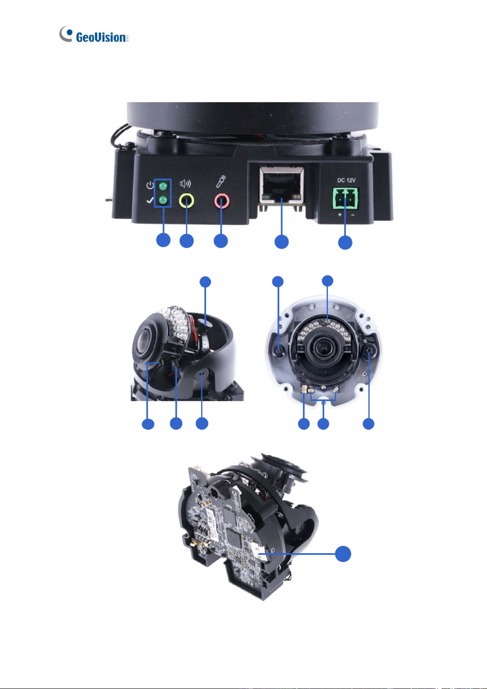
1.3 Overview
12 3 45
7
912
8
14
10 11 13
6
15
Figure 1-1
7

Getting Started
2
No. Name Description
1 LED Indicators
(top) turns on when the power is on and
The power LED
turns off when there is no power supply. The status LED
(bottom) turns on when the system operates normally and
turns off when an error occurs.
2 Audio Out Currently not functional.
3 Line In
e for audio input.
rnal
Connects to a microphon
Note: This interface only works with an exte
microphone with power supply.
4 LAN / PoE r PoE. Connects to a 10/100 Ethernet o
5 DC 12V Connects to power.
6 Rotational Screw camera. Loosens to rotate the
7 Conduit Connector
.
0-FR.
Waterproofs the Ethernet cable
Note: Not available for GV-FD870
8 Default Button ngs. For details, Resets the camera to factory default setti
see 7.2 Restoring to Factory Default Settings.
9 Focus Screw Adjusts the focus of the camera.
10 Zoom Screw Zoom the camera in or out.
11 Tilt Screw Loosens the screw to tilt the camera.
12 I/O Connector ee 1.6 I/O Connects to I/O devices. For details, s
Connectors.
13 Built-in Microphone
built-in microphone to record sound. For
Connectors
Connects to a
details, see 1.5 Connecting the Camera.
Note: Not available for GV-FD8700-FR.
14 Conduit Connector
FR.
Waterproofs the audio / I/O wires.
Note: Not available for GV-FD8700-
15 Memory Card Slot XC/UHSI, Class
10) to store recording data.
Contains a micro-SD card (SD/SDHC/SD
8

1 e Ca
This section introduces the standard installations of the cameras.
Note:
1. For optimal face recognition results, follow recommended guidelines to install the
camera. For details, see 5.3 Ideal Camera Position.
2. You can also install the camera to ceilings, wall corners (concave or convex), and poles
using optional mounting kits. For details on these installations, see GV-Mount
Accessories Installation Guide.
.4 Installing th mera
1.4.1 GV-VD8700
The camera is designed for outdoors. With the standard package, you can install the camera
on the ceiling.
1. Remove the housing cover with the supplied torx wrench.
Figure 1-2
9

Getting Started
2
2. Optionally remove the cables that attach
with installation.
the built-in microphone to the camera to assist
Cables for built-in microphone
Figure 1-3
e with the supplied torx wrench and remove the safety lock with a
eep the removed screw for later use.
3. Remove the back plat
Philips screwdriver. K
Safety lock
Figure 1-4
4. Thread wires into the camera.
A. Rotate the cap of the conduit connector. to remove
Figure 1-5
10

B. Unplug the conduit connector inside the housing and disintegrate the connector. You
should have
3 parts:
Figure 1-6
C. Thread the audio wires and I/O wires through the conduit entry and then through
parts 1, 2, and 3 of the conduit connector.
Tip:
1. To make the threading easier, it is recommended to thread the wires in the order
2. Use a pair of pliers to help you pull the wires through the camera.
described in Step 4-C.
11

Getting Started
2
If you use cat 5 Ethernet cable, there are 5 holes each labeled with its diameter. Remove th
plugs and push the wires to
e
the corresponding hole listed below:
Plug
Figure 1-7
1.9 mm: DIDO
Figure 1-8
IMPORTANT:
1. Use the supplied ruler and leave at least 14 cm of I/O wires and 10 cm of audio
wires between their connectors on the camera and the conduit connector.
2. The plugs are used to prevent water from entering the camera housing. Keep the
unused holes plugged and save the removed plugs for future use.
3. Only thread the wires through their designated holes on the conduit connector to
make sure the wires are properly sealed.
3.2 mm: Audio
12

If you use cat 6 Ethernet cable, thread the DC 12V wires through the conduit connector. Refer
the following figure for the corresponding holes and their diameter
to
s.
3.2 mm: Audio
1.9 mm: DIDO
1.9mm: DC 12V
Figure 1-9
IMPORTANT: Leave more than 10 cm of power wires between their connectors on the
camera and the conduit connector.
5. Install the Ethernet cable.
A. Rotate to remove the indicated cap and the plug inside.
Figure 1-10
13
7. Sort out the wires at the back. You can have the wires come out from positions A and B or
from C.
AB
C
Figure 1-12
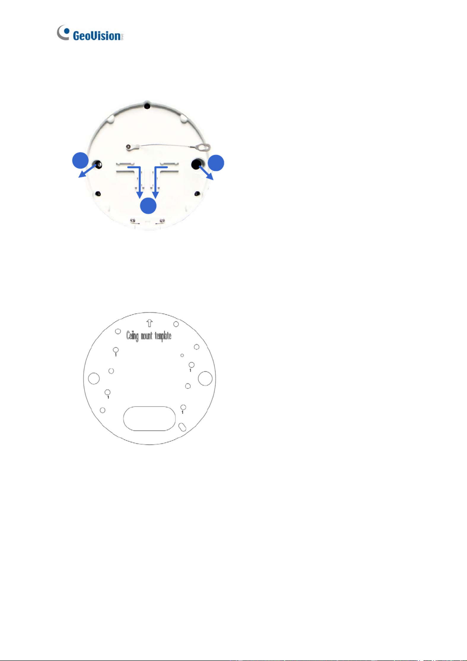
8. Secure the back plate to the ceiling.
A. Paste the sticker to the ceiling. The arrow on the sticker indicates the direction that
the camera faces.
Figure 1-13
B. Drill 4 holes for screws. The recommended ones are indicated as ‘1’.
C. Insert the screw anchors to the 4 holes.
. Drill holes A & B or only hole C for sorting out the wires according to Figure 1-12.
E. Secure the back plate to the ceiling with the supplied screws.
D
15

Getting Started
2
9. Secure the camera to the desired location.
A. Secure the safety lock to the camera with the screw you removed from the back plate
in Step 2.
Safety lock
Figure 1-14
B. Thread all the wires into the ceiling and connect them.
C. Secure the camera to the back plate with the supplied torx wrench.
10. Access the live view. See 2.3 Accessing Your Surveillance Image.
16

Getting Started
2
12. Replace the silica gel bag, organize the wires and secure the camera cover with the torx
wrench.
Organize
the wires
to avoid
blocking
the lens
Figure 1-16
1.4.2 GV-FD8700-FR
The camera is designed for indoors. With the standard package, you can install the c era
on the ceiling or the wall. Before installation, make sure the installing site is shielded from rain
and
1. Use the supplied torx wrench to loosen three screws on the housing cover, and take out
the camera body.
am
moisture.
Figure 1-17
18

2. Place the installation sticker where you want to install it, and make 3 marks on the ceiling
or the wall for screw anchors
Figure 1-18
3. Drill the marks and insert the screw anchors.
4. Connect the ca etwork and power. For details, see 1.5 Connecting the Camera. mera to n
5. Secure the camera to the ceiling or the wall with the supplied screws.
6. Access the live view. For details, see 2.3 Accessing Your Surveillance Images.
7. Loosen the tile screw, pan screw or rotational screw. Adjust the angles based on the live
view as needed, and tighten the screws again. See Figure 1-15 for illustrations.
8. Remove the indicated part in the housing cover for wiring through the cables if necessary.
Place the housing cover back and tighten the three screws to secure it.
Figure 1-19
19
Getting Started
2
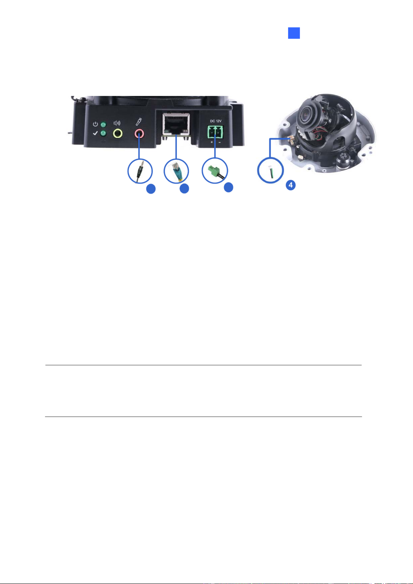
1.5 Connecting the Camera
13
2
Figure 1-20
1. Use a standard network cable to connect the camera to your network.
2. Optionally connect an external microphone.
3. Connect power using one of the following methods:
Plug the power adapter to the power port.
Use the Power over Ethernet (PoE) function and the power will be provided over the
network cable.
wi l be suppor
4. Optionally connect to input / output devices. For details, see 1.6 I/O Connector.
5. The status LED of the camera will be on.
Note:
1. The speaker interface l ted in the near future.
2. The micr ace only works with external microphone with power supply. ophone interf
20

21
The camera supports one digital input and one digital output of dry contact.
1.6 I/O Connector
Pin Supplied I/O Cable Function
1 Green Digital Output
2 Black GND
3 White Digital Input
For details on how to enable an installed I/O device, see 4.2.4 I/O Control.

Getting Started
2
Chapter 2 Getting Started
.1 Looking Up the IP Address
B a gned amic IP address by the DHCP server when the
ca ra is connected to the networ ss remains unchanged unless you unplug
or co our camera from th ork.
2.168.0.10. In
this case, it is strongly recommended to modify the IP address to avoid IP address conflict
with other GeoVision IP devices on the same LAN. To change the IP address, see 2.2
Changing the IP Address later in this chapter.
2
y def ult, the camera is assi with a dyn
me k. This IP addre
dis nnect y e netw
Note: If your router does not support DHCP, the default IP address will be 19
Follow the steps below to check the camera’s dynamic IP address:
1. Download and install the GV-IP Device Utility program from our website.
Note: The PC installed with GV-IP Device Utility must be under the same LAN as the
camera you wish to configure.
2. On the PC desktop, select Start, point to Programs and select GV IP Device Utility. The
Utility window appears and automatically searches for the IP devices on the same LAN.
3. Click the Name or Mac Address column to sort.
22

4. Find the Mac Address of the camera to see its IP address.
Figure 2-1
Whe the DHCP server on your network is unavailable or disabled, the camera can be
b
setting page.
2.2 Changing the Static IP Address
n
accessed by the default IP 192.168.0.10. To modify the static IP address, log in the We
interface to access the network
1. Open your Web browser, and type the default IP address http://192.168.0.10.
2. In both Login and Password fields, type the default ID and password admin. Click Apply.
twork and click LAN Configuration to
begin the network settings. This page appears.
3. On the top bar, go to System Settings. Select Ne
Figure 2-2
4. Select Static IP address and type the required network information.
5. Click Apply. The camera is now accessible through the static IP address.
23

Getting Started
2
IMPORTANT:
1. Use the dynamic DNS Service to obtain a domain name linked to the camera’s changing
IP address before you start using the dynamic IP address. For details on Dynamic IP
Address, see 4.3.2 Advanced TCP/IP and 4.3.1 LAN Configuration.
2. If Dynamic IP Address is enabled and you cannot access the camera, you may have to
reset it to the factory default settings and perform the network settings again. To restore
the factory settings, see 7.2 Restoring to Factory Default Settings.
24
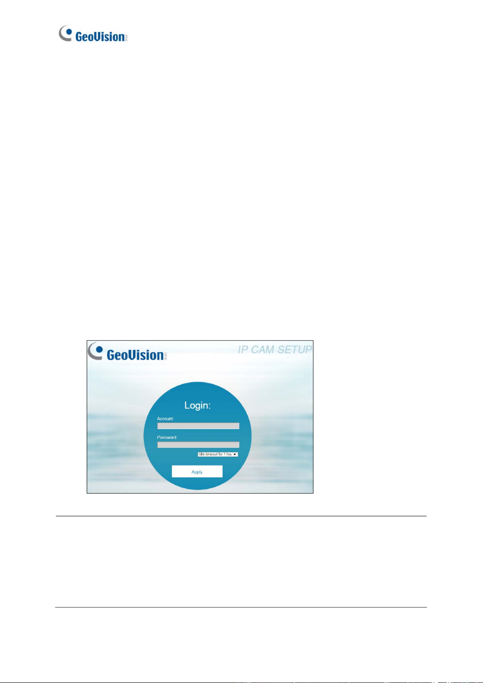
2.3 Accessing Your Surveillance Images
1. Open the Internet Explorer or Chrome browser.
2. Type the IP address or domain name of the camera in the Location/Address bar of your
browser. To look up the IP address, see 2.1 Looking Up the IP Address.
3. Enter the login name and password. The administrator account has unrestricted access to
all the features and functions. The guest account is restricted to have the access of only
the live view and network status information.
The default login name and password for Administrator are admin.
The default login name and password for Guest are guest.
Two types of users are allowed to log on to the camera: Administrator and Guest. The
Administrator has full access to all system configurations, while the Guest can only access the
live view and network status.
Once the camera is connected to the network, follow these steps to access your surveillance
images:
Figure 2-3
Note:
1. The default ID and Password are no longer supported in the latest version. For the
first-time user, after entering admin in both lD and password fields, you will be
requested to change the login credentials.
2. On the login page, you can select an idle timeout to sign out of the account after a
period of inactivity.
25
Getting Started
26
2
r browser. 4. A video image, similar to the example below, is now displayed on you
Figure 2-4
Note: To enable the updating of images in Microsoft Internet Explorer, you must set your
ion of GeoVision’s
ActiveX component onto your computer.
browser to allow ActiveX Controls and perform a once-only installat
2.3 Configuring the Basics
Once you have logged in to the camera, you are ready to configure some of its primary
settings through the Web interface:
Date and time adjustment: see 4.4.1 Date & Time.
Login and privileged passwords: see 4.4.2 User Account.
Network gateway: see 4.3 Network.
Camera image adjustment: see 3.2 The Control Panel of the Live View Window.
.
deo
ol Panel of the Live View Window.
Audio settings adjustment: see 4.1.2 Audio Settings.
Video format, signal format, resolution and frame rate: see 4.1.1 Video Settings
IMPORTANT: If you are using a 50 Hz flicker, set the Flickerless value to 50 Hz. See Vi
Attributes in 3.2 The Contr

Chapter 3 Accessing the Live View
3.1 The Live View Window
This section introduces the features of the Live View window and Network Status on the
main page.
1234 5
6
7
Figure 3-1
No. Name Function
1 Play Plays live video.
2 Stop Stops playing video.
3 Snapshot Takes a snapshot of live video.
--- See 3.3 Snapshot of a Live Video.
4 Full Screen Switches to full screen view.
5 File Save Records live video to the local computer.
--- See 3.4 Video Recording.
6 Control Panel
Adjust these image quality settings: Video Attribute, Orientation,
Flickerless, Shutter Speed, Auto Iris, DN, DN Sensitivity,
White Balance, . WDR, IR Light, and BLC
--- See 3.2 The Control Panel of the Live View Window.
27

Accessing the Live View
3
7 Pop-up Menu
On the Live View window, right-click the image to have these
options:
Snapshot: Takes a snapshot of live videos.
Full Screen: Switches to full screen view.
PIP: Enables an inset window for a close-up view on the
video. See 3.5 Picture-in-Picture View.
Audio: Receives audio from the surveillance site.
Information: Shows the information on codec, resolution,
frames per second and transmission speed of the video
stream.
28

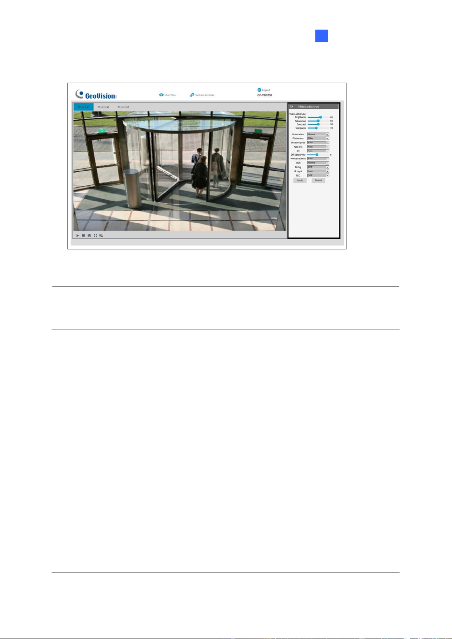
3.2 The Control Panel of the Live View Window
The control panel is on the right side of the Live View window. You can adjust the settings of
the following functions on the control panel. Note these settings are only accessible for
Administrator.
The Control
Panel of the
Live View
Figure 3-2
[Video Attributes] Adjusts the image quality settings.
Brightness: Adjusts the brightness of the video image.
Saturation: Adjusts the saturation of the video image.
Contrast: Adjusts the relative differences between one pixel and the next.
Sharpness: Adjusts the sharpness of the video image.
Orientation: Changes the image orientation on the Live View window.
Flickerless: The camera automatically matches the frequency of your camera’s image to
the frequency of indoor light sources, e.g. fluorescent lighting. You can also select 50 Hz
or 60 Hz manually. If these don’t match, faint light and dark bars may appear in your
images. Check the power utility to determine which frequency is used at your area.
29

Accessing the Live View
3
Shutter Speed: Shutter speed controls the amount of light entering the image sensor
and directly impacts the quality of image presentation. A slower shutter speed allows
higher light exposure, which creates a brighter overall image and brings out background
details, but blurs moving objects. A faster shutter speed is able to capture motion at the
cost of lowering color and image clarity. The minimum shutter speed ranges from 1/30 to
1/8000 sec. In low light conditions, a fast shutter speed will lower color quality and image
clarity. In this case, select the Auto option for automatic shutter control.
Auto Iris: This function is enabled by default. Select Auto from the drop-down list when
the scene appears fuzzy and the Flickerless function does not help to improve the
situation. Select Max to set the aperture of the camera to its maximum regardless of the
illumination of the environment.
D/N: Select Auto for automatic switch between day mode and night mode depending on
the amount of light detected. Select Black and White to switch the camera to night mode.
Select Color to switch the camera to day mode. Select Specified Time to specify a
period of time to enable night mode. Set the light sensor’s sensitivity of switching
between day mode and night mode, from 1 to 10. The higher the value, the more
sensitive the camera is to light.
White Balance: The camera automatically adjusts the color to be closest to the image
you are viewing. You can choose one of the four presets: Auto, Outdoor, Fluorescent,
and Incandescent. You can also choose Manual to adjust the white balance manually.
Wide Dynamic Range: Adjusts and generates clear live view when the scene contains
very bright and very dark areas at the same time. Select Strong to bring out details of the
dark areas of the scene or Normal for a balanced effect.
Defog: Select Auto to automatically enhance the visibility of images. Select Off to
disable the function.
IR Light: Select Auto to automatically enhance the visibility of images. Select Off to
disable the function.
BLC: Select On to adjust the color intensity of scenes with strong light at the background
or select Off to disable the function. You can also choose Manual to set the Start Time
and End Time when the specified BLC adjustment will be activated and terminated.
Click Apply to save the configuration after the settings are completed. The changes take
effect only after the configurations have been saved.
30

3.3 Snapshot of a Live Video
To take a snapshot of live video, follow these steps:
1. Click the Snapshot button (No. 3, Figure 3-2). The Save As dialog box appears.
2. Specify Save in, type the File name and select JPEG or BMP as Save as Type. You may
also choose to display the camera name and/or the date, the text color and image quality
of the snapshot.
3. Click the Save button to save the image in the local computer.
3.4 Video Recording
You can record live video to your local computer. To do so, follow the steps below:
1. Click the File Save button (No. 5, Figure 3-2). The Save As dialog box appears.
2. Specify Save in, type the File name and move the Time Period scroll bar to specify the
time length of each video clips from 1 to 5 minutes.
3. Click the Save button to start recording.
4. To stop recording, click the Stop button (No. 2, Figure 3-2).
31
Accessing the Live View
32
3
3.5 Picture-in-Picture View
The full screen mode provides a particular type of close-up view: Picture-in-Picture (PIP).
With the Picture-in-Picture (PIP) view, you can zoom in on the video to get a close-up view.
Inset window
Navigation box
Figure 3-3
1. Right-click the live view and select PIP. An inset window appears.
2. Click the inset window. A navigation box appears.
3. Move the navigation box around in the inset window to have a close-up view of the
selected area.
4. To adjust the navigation box size, move the cursor to any of the box corners, and enlarge
or diminish the box.
5. To exit the PIP view, right-click the image and click PIP again.

33
Chapter 4 Administrator Mode
The Administrator can access and configure the camera over the network. The configuration
categories include: Audio & Video Settings, Event and Alerts, Network and Management.
Figure 4-1
Corresponding Sections for Configuration Menu
Find the topic of interest by referring to the indicated section.
4.1 Audio & Video Settings
4.1.1 Video Settings
4.1.2 Audio Settings
4.1.3 RTSP
4.1.4 Privacy Mask
4.1.5 Text Overlay
4.2 Events and Alerts
4.2.1 Face Recognition
4.2.2 Tampering Alarm
4.2.3 Motion Detection
4.2.4 I/O Control
4.2.4.1 Input Settings
4.2.4.2 Output Settings
4.2.5 E-mail
4.2.6 Event Manager
4.3 Network
4.3.1 LAN Configuration
4.3.2 Advanced TCP/IP
4.3.3 IP Filtering
4.4 Management
4.4.1 Date and Time
4.4.2 User Account
4.4.3 Tools
4.4.4 External Storage Settings
4.4.5 System Log

Administrator Mode
4
4.1 Audio & Video Settings
The camera supports three streams, Streaming 1, Streaming 2, and Streaming 3, which allow
separate codec and resolution settings for a single video transmission. In a bandwidth-limited
network, such as mobile phone surveillance, this multi-stream feature allows you to view live
video in lower resolution and codec (Streaming 2 / Streaming 3), and record in highest
resolution 3840 x 2160 and codec H.265 (Streaming 1) at the same time.
4.1.1 Video Settings
You can configure your video stream settings, such as H.264/H.265 video format, resolutions,
frame rate, etc. or enable / disable streaming 2 and streaming 3 in Video Settings.
Figure 4-2
Note: Streaming 3 is disabled by default. To enable streaming 3, change the video
resolution of streaming 1 to 2560 x 1440 (16:9) or lower.
34

[Video Format] Select either H.265 or H.264 as codec type.
[Resolution]
Configure the resolution. The supported resolutions are listed below:
Streams Ratio Supported Resolution
Streaming 1 3840 x 2160, 2560 x 1440, 1920 x 1080, 1280 x 720
Streaming 2 1280 x 720, 640 x 360
Streaming 3
16:9
640 x 360
Streaming 1 2560 x 1920, 2048 x 1536, 1600 x 1200, 1280 x 960
Streaming 2 1024 x 768, 640 x 480, 320 x 240
Streaming 3
4:3
640 x 480, 320 x 240
[Frame per Second] Select a specific frame rate for video streams from the drop-down list.
[Bandwidth Management]
You can configure the bitrate settings to control bandwidth usage.
VBR (Variable Bitrate): The quality of the video stream is kept as constant as possible at
the cost of a varying bitrate. The bandwidth is much more efficiently used than a
comparable CBR. Set the image quality to one of the 5 standards: Poor, Fair, Good,
Great or Excellent.
CBR (Constant Bitrate): CBR is used to achieve a specific bitrate by varying the quality
of the stream. The bitrates available for selection depend on the image resolution.
[GOP]
Set the maximum number of seconds between every key frame. The default is 2 (seconds).
35

Administrator Mode
4
4.1.2 Audio Settings
You can enable the microphone and adjust the audio quality to Low or Normal. Select
Built-in Microphone or External Microphone as the source of audio input.
Figure 4-3
Note:
1. GV-FD8700-FR is not equipped with built-in microphone.
2. The microphone input interface only works with external microphone with power supply.
For details, see 1.5 Connecting the Camera.
36

4.1.3 RTSP
The RTSP enables video and audio streaming to your 3G-enabled mobile phone. The RTSP
streaming is enabled by default.
Figure 4-4
[Enable Audio] Turns audio streaming on or off.
[Authentication] The ID and password of the camera are required to access the camera
through RTSP connections. This function is disabled by default.
[RTSP/TCP Port] Keep the default value 8554, or modify it if necessary.
[RTP/UDP Port] Keep the default range from 1024 to 65535, or modify it if necessary. The
number of ports for use is limited to 20.
[Max Connection] Set the maximum number of RTSP and 3GPP connections to the camera.
The maximum value is 8.
37

Administrator Mode
4
4.1.4 Privacy Mask
You can use the Privacy Mask to block out sensitive areas on live view and recorded clips.
This feature is ideal for scenes with displays, keyboard sequences (e.g. passwords), and for
anywhere else you don’t want sensitive information visible.
Figure 4-5
1. Drag the area(s) where you want to block out on the image.
2. Click Apply to save all the settings.
3. To delete the latest privacy mask you had marked, click Delete.
4. To delete all privacy masks you had marked, click Reset and click OK.
Note: You cannot set more than 4 privacy masks on the camera image.
38

4.1.5 Text Overlay
The Text Overlay allows you to overlay the camera name and date & time on the camera view.
Up to 33 characters can be created on one camera view. The overlaid text will be saved in the
recordings.
Figure 4-6
[Name] Type the camera name in the Name field.
[Overlaid with Camera Name] Display the camera name on the designated area on the
camera view. You can choose to place the text on the Left Top, Left Down, Right Top or
Right Down of the camera view.
[Overlaid with date stamps time] Display the current date and time on the designated area
on the camera view. You can choose to place the text on the Left Top, Left Down, Right Top
or Right Down of the camera view.
[Font Size] Choose Small, Normal or Big fonts using the drop-down list.
39

Administrator Mode
4
4.2 Event and Alerts
For the events of motion detection, tampering alarm or I/O trigger and face groups, the
Administrator can set up triggered actions to send a snapshot by e-mail and / or activate an
output device.
To have above triggered actions, you must also set the following features:
Tampering Alarm ( See 4.2.2 Tampering Alarm)
Motion Detection (See 4.2.3 Motion Detection)
Input Setting (See 4.2.4.1 Input Settings)
Output Setting (See 4.2.4.1 Output Settings)
Face Groups (See 5.6.5 Trigger Area)
4.2.1 Face Recognition
You can configure the face recognition settings in this page. For details, see 5.6 Face
Recognition Basic Settings
40

4.2.2 Tampering Alarm
Tampering Alarm is used to detect whether a camera is being physically tampered. An alarm
can be generated when the camera is moved, covered up, or out of focus. The alarm types
include output triggers and email alerts.
Figure 4-7
1. Select the Enable option.
2. Enable Dark Image to trigger an alarm when the scene turns dark, e.g. when the lens of
the camera is covered up. By default, this function is disabled.
3. Select the desired detection sensitivity under Sensitivity. The higher the value, the more
sensitive the camera is to scene changes.
4. In the Dwell Time when triggered (seconds) field, specify the time length allowed for
scene changes before an alarm is generated.
5. To trigger the e-mail alert when a tampering event occurs, enable E-Mail Output.
6. To trigger the output device when a tampering event occurs, enable I/O Output.
7. If you want the camera to ignore any movement or scene change in certain areas, click
the screen to drag areas on the camera view. Click Delete to delete the latest masked
area. Click Reset to delete all masked area.
8. Click Apply to save all the settings.
For details on setting up the e-mail server and output device, see 4.2.5 E-Mail and 4.2.4.2
Output Settings.
41

Administrator Mode
4
4.2.3 Motion Detection
Motion detection is used to generate an alarm whenever movement occurs in the video image.
You can configure up to 4 areas with different sensitivity values for motion detection. Set up at
least one area to enable this function.
Figure 4-8
1. Select the desired sensitivity under Sensitivity. There are ten values. The higher the
value, the more sensitive the camera is to motion.
2. Drag an area on the image.
3. To create several areas with different sensitivity values, repeat steps 1 and 2.
4. Click Delete to delete the selected areas.
5. Click Reset to delete all the selected areas.
6. Select Enable to activate the e-mail alert and / or output alarm.
7. Click Apply to save the above settings.
For details on setting up the e-mail server and output device, see 4.2.5 E-Mail and 4.2.4.2
Output Settings.
42

4.2.4 I/O Control
After installing the I/O device, you need to enable the I/O settings on the camera. For installing
the I/O device on the camera, see 1.6 I/O Connector.
4.2.4.1 Input Settings
To activate the sensor input, select Enable.
Figure 4-9
Name: Name the input in the Name field.
Normal State: Set the input state to trigger actions by selecting Open Circuit (N/O) or
Grounded Circuit (N/C).
E-Mail Output: Enable this option to send alerts to a specified e-mail address when the
input is triggered.
I/O Output: Enable this option to trigger the output once the input is activated.
For details on setting up the e-mail server and output device, see 4.2.5 E-Mail and 4.2.4.2
Output Settings.
43

Administrator Mode
4
4.2.4.2 Output Settings
Select Enable to start the output device.
Figure 4-10
Name: Name the output in the Name field.
Normal State: Choose the output signal that best suits your device: Open Circuit (N/O)
and Grounded Circuit (N/C).
I/O Output Type: Choose Normal for the output to remain in effect until the trigger action
stops. Or choose Pulse for the output to last only for the amount of time you specified.
Pulse Time (seconds): Specify the time (seconds) for the pulse-type output to last.
44

4.2.5 E-mail
After an event is triggered, the camera can send an e-mail to a remote user containing a
snapshot.
IMPORTANT:
To send e-mail alert upon motion, be sure to set up the detection area on the
Motion Detection page. For details, see 4.2.3 Motion Detection.
Figure 4-11
To enable the e-mail functions:
1. Select Enable to set up e-mail notifications.
2. Server URL/IP Address: Type the server’s URL address or IP address.
3. Server Port: Type the server’s port number. Or keep the default value 25.
4. From email address: Type the sender’s e-mail address.
5. Send to: Type the e-mail address(s) you want to send alerts to.
6. Alerts interval time in minute: Specify the interval between e-mail alerts. The interval
can be between 0 and 60 minutes. The option is useful for frequent event occurrence.
Any event triggers during the interval period will be ignored.
7. If the server needs authentication, select Need authentication to login and type a
valid Username and Password to log in to the server. If the server needs a secure
connection (SSL), select This server requires a secure connection.
8. Click Apply to save the settings.
For related settings of e-mail alerts, see 4.2.2 Tampering Alarm, 4.2.3 Motion Detection,
and and 4.2.4 I/O Control 4.4.4 External Storage Settings.
45

Administrator Mode
4
4.2.6 Event Manager
You can set up the connection to GV-FWC Server and integrate 3
rd-party software through
Http settings.
Figure 4-12
[Settings] After setting up HTTP Event and/or GV-FWC in their separate pages under the
Event Manager, you need to enable their functions here to activate the connection.
[Send events when faces in the selected group(s) detected] Send the events to GV-FWC
Server or 3rd-party software when any face of the selected groups is detected.
[Send events when faces are unknown] Send the events to 3
rd-party software when a face
fails to be recognized from the database. Note the function is not supported by GV-FWC
Server.
[Limit the number of seconds to ignore the identical faces] Set up the event frequency by
specifying the number of seconds to ignore the events of identical faces detected.
46

Administrator Mode
4
[Network Status Information]
In this tab, you can view the current network status.
Figure 4-14
48

4.3.2 Advanced TCP/IP
This section introduces the advanced TCP/IP settings, including DDNS Server, HTTP port,
and HTTPS.
Figure 4-15
[Dynamic DNS Server Settings]
DDNS (Dynamic Domain Name System) provides a convenient way of accessing the camera
when using a dynamic IP. DDNS assigns a domain name to the camera, so that the
Administrator does not need to go through the trouble of checking if the IP address assigned
by DHCP Server or ISP (in xDSL connection) has changed.
Before enabling the DDNS function, the Administrator should apply for a Host Name from the
DDNS service provider’s website. There are 2 providers listed in the camera: GeoVision
GVDIP or DynDNS.org.
49

Administrator Mode
4
To enable the DDNS function:
1. Select Enable.
2. Select the DDNS service provider you have registered with. If you do not have a DDNS
provider, you can click on Register GeoVision DDNS Server to register the service via
GeoVision DDNS V2 and obtain a host name.
Figure 4-16
3. Type the Host Name used to link to the camera. For the users of GeoVision DDNS Server,
it is unnecessary to fill the field because the system will detect the host name
automatically.
4. Type the User Name used to enable the service from the DDNS. The user name should
look similar to your host name. Depending on your service provider, you should add
domain name (.dipmap.com, .gvdip.com or .org) after your user name, for example,
alice.dipmap.com
5. Type the Password used to enable the service from the DDNS.
6. Click Apply to save the settings.
50

[HTTP Port Settings]
The HTTP port enables connecting the camera to the Web. For security integration, the
Administrator can hide the server from the general HTTP port by changing the default HTTP
port of 80 to a different port number within the range of 1024 through 65535.
Figure 4-17
[HTTPS Settings]
By enabling the Hypertext Transfer Protocol Secure (HTTPS) settings, you can access the
camera through a secure protocol.
Figure 4-18
51

Administrator Mode
4
4.3.3 IP Filter
The Administrator can set IP filtering to grant or restrict access to the camera. Note that you
can only set up 4 filter entries for the camera.
Figure 4-19
To enable the IP Filter function:
1. Enable IP Filtering: Enable the IP Filtering function.
2. Filtered IP: Type the IP address you want to grant or restrict access to.
3. Action to take: Select the action of Allow or Deny to be taken for the IP address(es) you
have specified.
4. Click Apply to save the settings.
52

4.4 Management
The Management section includes the settings of date, time and user account. You can also
view the firmware version and execute certain system operations.
4.4.1 Date and Time
The date and time settings are used for date and time stamps on the image.
Figure 4-20
[Date & Time on IP Camera] Displays the current date and time of the camera.
[Time Zone] Sets the time zone for local settings.
[Synchronized with a Network Time Server] By default, the camera uses the timeserver of
tw.pool.ntp.org to automatically update its internal clock every 24 hours. You can change the
host name or IP setting to the timeserver of interest. To change the time of automatic update,
select an update period and the use the drop-down lists to specify the time.
[Synchronized with your computer or modify manually] Manually changes the camera’s
date and time. Or, select Synchronized with your computer to synchronize the camera’s
date and time with those of the local computer.
53

Administrator Mode
4
4.4.2 User Account
You can change the login name and password of Administrator and the Guest user accounts.
Figure 4-21
54

4.4.3 Tools
This section allows you to execute certain system operations and view the firmware version.
Figure 4-22
[Device Settings] You can reboot the camera, restore the camera to its factory default
settings, or import / export the system settings.
Reboot: Click Reboot for the camera to perform a software reset.
Default: Click Default to restore the camera to factory default settings.
Export System Settings: Click to export the configurations of the camera to the local PC.
Import System Settings:
Click Browse to locate the system file (.config) and click
Import System Settings to import previously saved configurations to the camera. Log in
again after the Import completes.
[System Information] This field displays the firmware version of the camera.
[Firmware Upgrade] Upgrade the firmware over the Internet. For details, see 7.1 Upgrading
System Firmware.
[Language] Select the language and click Apply to save the settings.
[Disconnection Record] When the camera is disconnected from GV-DVR / NVR / VMS, the
recordings of alarm events will be temporarily saved to the camera’s memory card. The
recordings will later be uploaded to a predefined FTP server when the network connection is
resumed. After all the recordings are uploaded to the FTP, the temporary recordings on the
memory card will be removed.
IMPORTANT: Format the micro-SD card before its first use. For details, see 4.4.4 External
Storage Settings
55

Administrator Mode
4
Disconnection Record: Select On to enable the service.
Video Time Interval (minutes): Choose the duration time between 1, , , 234, or 5
minutes. When the recording starts once the camera is disconnected from GV-DVR / NVR
/ VMS, the camera will record videos for the specified time period.
Upload video to an FTP server: Select On to upload the recordings to an FTP server.
Type the settings of your FTP server in the following fields: Server URL / IP Address,
Server Port, User Name, Password and the name of the storage folder on the FTP
server in Remote Directory.
56

4.4.4 External Storage Settings
You can view the memory card information in this page. Format the memory card before using
it for the first time. After being formatted, the memory card will be ready to use. To insert or
remove a SD card, see 1.3 Overview.
Figure 4-23
[Tools]
Disable: DisableWhen you click , the recordings that are saved to the memory card
and the snapshot of face recognition become inaccessible. The Format button and the
Unmount button become active only when you clicked Disable.
Format: Click Format to clear the content of SD card.
Unmount: Click Unmount to disengage the SD card from the camera.
[MicroSD Abnormal Notification] Select Enable to activate the e-mail alert upon
micro-SD card abnormality.
For details on setting up the e-mail server, see 4.2.5 E-Mail.
Note: The recording data may be lost if you remove the memory card during recording.
57

Administrator Mode
58
4
4.4.5 System Log
The log contains dump data that is used by service personnel for analyzing problems.
Figure 4-24
Clear: Click Clear to delete all system logs.
Download: Click Download to download all system logs to your computer.

Chapter 5 Face Recognition
GV-VD8700 and GV-FD8700-FR can detect for and identify persons’ faces from its
predefined database. Upon successful recognition, the name of the person identified is
displayed on the live view while the related data are recorded into the camera as a recognition
event, as exemplified by the figure below. Those who are detected but failed to be recognized
within the database are recorded as “unknown”.
Read the following sections to learn how to improve the efficiency and accuracy of face
recognition, particularly in regards to variables, such as the movement speed and facial
direction of the recognition target. It is recommended to install the camera in places where the
targets are facing right at the camera and remain focused for a maximized depth of field. It is
also essential to arrange proper lighting conditions to avoid high contrast and backlighting that
obscures the recognition target. See 5.2 Installation Flowchart for a step-by-step guide of the
installation.
Figure 5-1
59

Face Recongition
5
5.1 Features
Store up to 10,000 face data entries
Recognize up to 10 faces simultaneously
Maximum recognition distance of 4 meters (13.12 ft)
Minimum recognition time of 2 seconds
Output alarm trigger through face group settings
Store up to 7 days of face recognition results and up to 3 GB of face recognition
snapshots
60

5.2 Installation Flowchart
Follow the step-by-step guide to set up face recognition and refer to the relevant sections if
needed.
Figure 5-2
61

Focus: A large depth of field not only ensures an appropriate image size for the faces of
the recognition targets, but also allows them to stay in focus for a longer period of time,
thereby increasing the recognition accuracy. Calibrate the lens at the telephoto end for
effective recognition at its optimal recognition distance of 4 m (13.12 ft).
Loosen the screw
Telephoto End
Figure 5-4
Range: The recognition result is at its best when the target walks straight to the camera.
When the target deviates laterally, recognition is still possible as long as the target stays
within a 15 degree range. The camera is unable to recognize the faces when the
deviation exceeds 15 degrees.
<15°
Recognizable
<15°
Recognizable
>15°
Unrecognizable
Figure 5-5
63

Face Recongition
5
5.4 Adjusting Illumination
After installing the camera properly, it is required to adjust the environment’s lighting since the
recognition process may vary depending on the illumination. Follow the guidelines below to
set up the environment’s lighting according to Daytime, Nighttime and Low Illumination
(WDR) recognition needs.
5.4.1 Daytime
Make sure the following criteria are met to achieve optimal recognition performance in
daytime:
Less Ideal Installation Scenario Recommended Installation Scenario
Insufficient Lighting Sufficient Lighting
Fast Moving Target Target Moving at a Constant Speed
(1/60 Second Shutter Speed)
Results
Less Ideal Recognition Performance Best Recognition Performance
Lighting: Sufficient light is required for effective recognition results, as moving targets
often cause motion-blurred images under insufficient lighting.
Shutter Speed: Adjust the shutter speed to 1/60 seconds manually when the camera is
installed in places with high flow of people such as hallways.
64
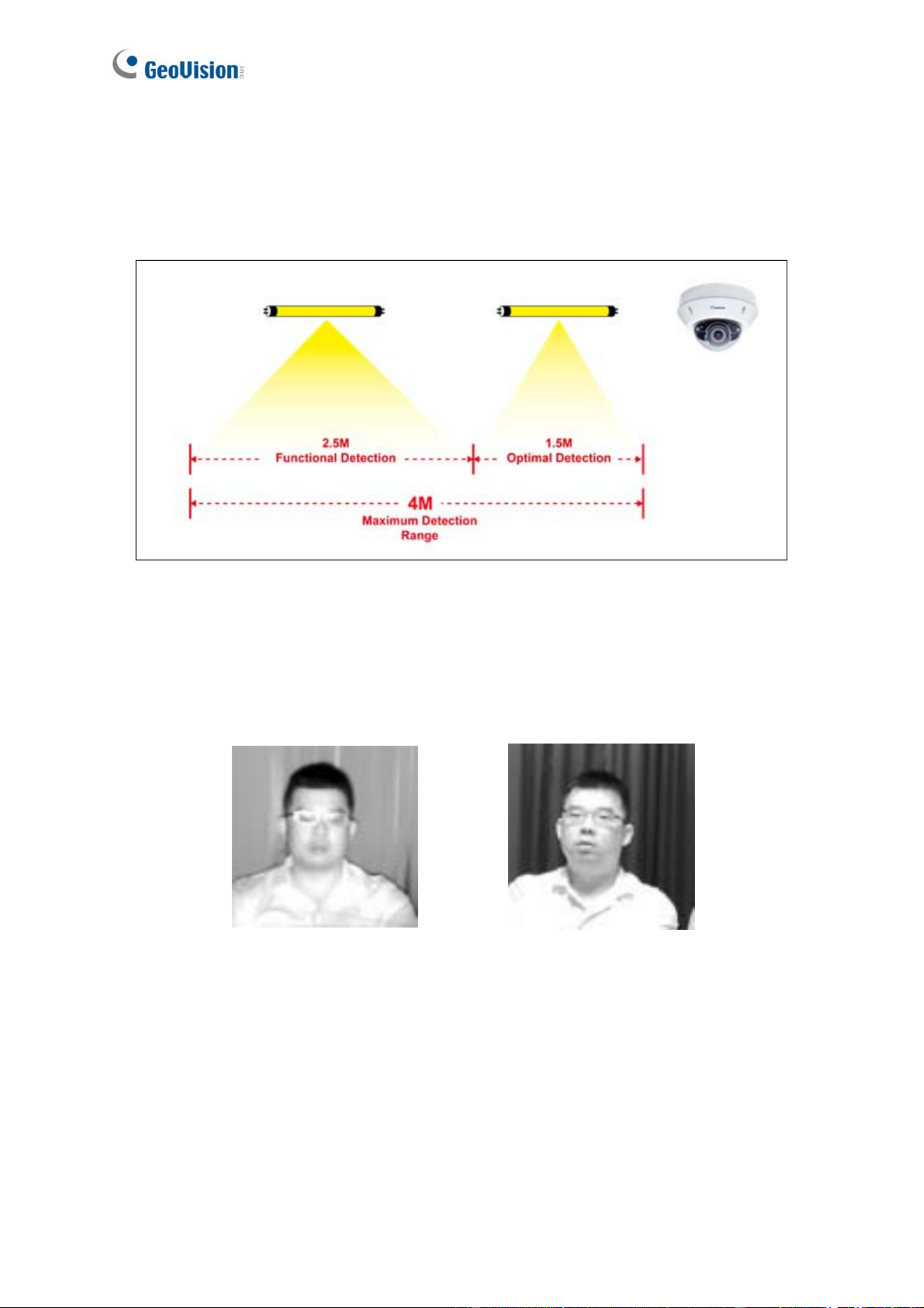
5.4.2 Nighttime
If you found recognition results to be less optimal at night, you can use extra IR LED tubes as
a lighting aid for the camera or create extra face data under IR LED illumination. Both
methods can be applied to achieve optimal face recognition results at night.
Figure 5-6
Extra IR LED Tubes: Install additional IR LED tubes at the surveillance site to illuminate
the recognition range.
Internal IR LED only With the aid of
extra IR LED Tube
Relying solely on the internal IR
LED can cause overexposure,
which may lead to misrecognition
Increasingly better recognition
results occur under stable
illumination of extra IR LED tubes.
Figure 5-7
Enroll face data under special light conditions: Enroll additional face data for objects
under IR LED illumination. See 5.5 Enrolling Face Data.
65

Face Recongition
5
5.4.3 Low Illumination (WDR)
Intense lighting contrast in an environment may cause ineffective recognition results. In this
case, there are two ways to compensate for recognition accuracy:
Apply Wide Dynamic Range (WDR) or Back Light Compensation (BLC): By default,
the WDR function is enabled. If recognition results are still ineffective with the WDR on,
adjust the WDR settings to Strong and enable the BLC settings. To adjust WDR or BLC
settings, see 3.2 The Control Panel of Live View Window.
Without Applying WDR
or BLC WDR WDR (Strong) and BLC
Figure 5-8
Enroll face data under special light conditions: Enroll additional face data for objects
under WDR and BLC illumination. See 5.5 Enrolling Face Data.
66

5.5 Enrolling Face Data
After the camera and the environment’s lighting are set, it is required to create the face data
by adding photos of the persons to be recognized into the Face Database of the camera.
To enroll Face Data:
1. Click System Settings. Then in the left menu, click Events and Alerts, select Face
Recognition and click the Management tab.
2. Click on the upper-right corner. A dialog box appears.
Figure 5-9
67
Face Recongition
5
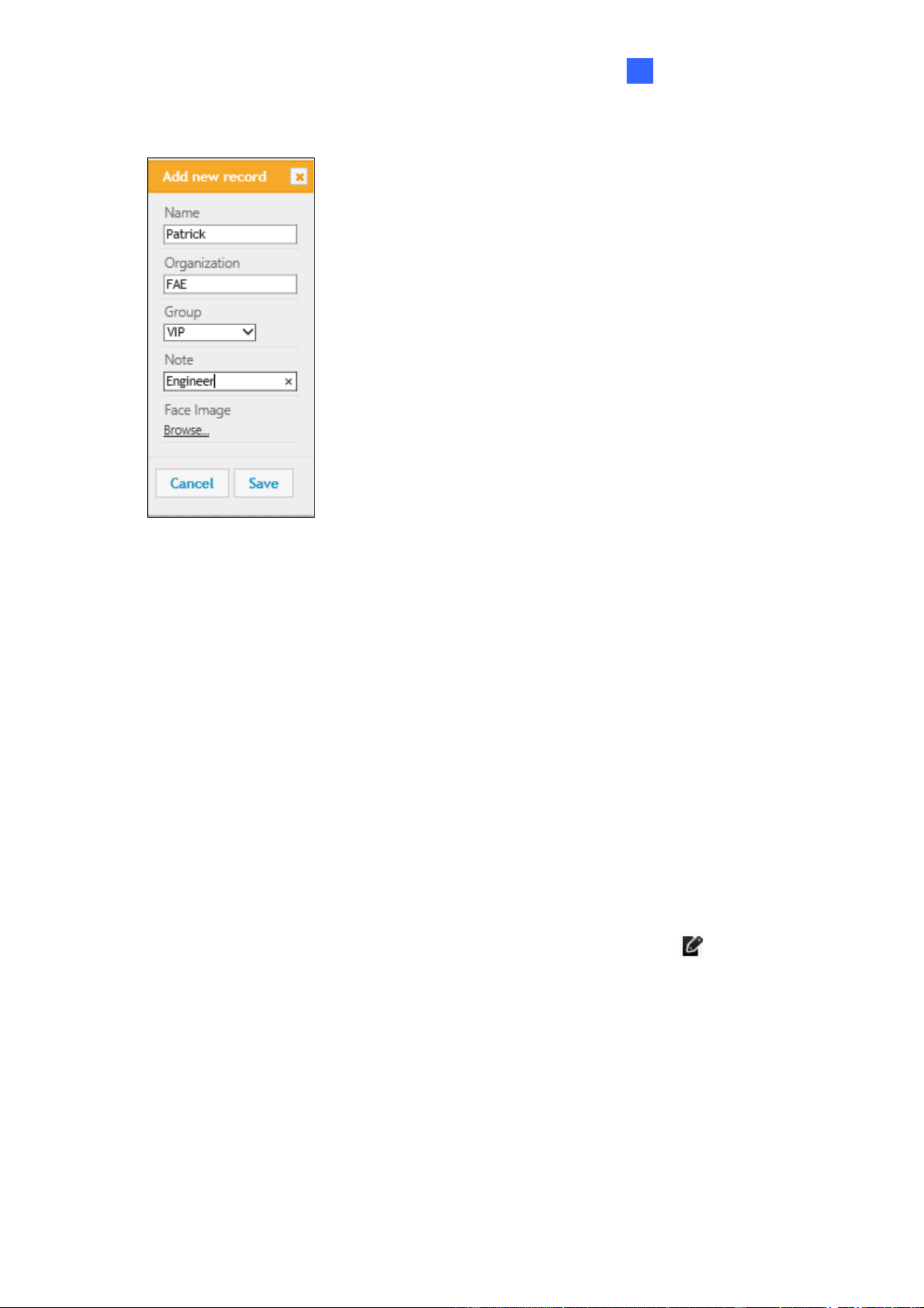
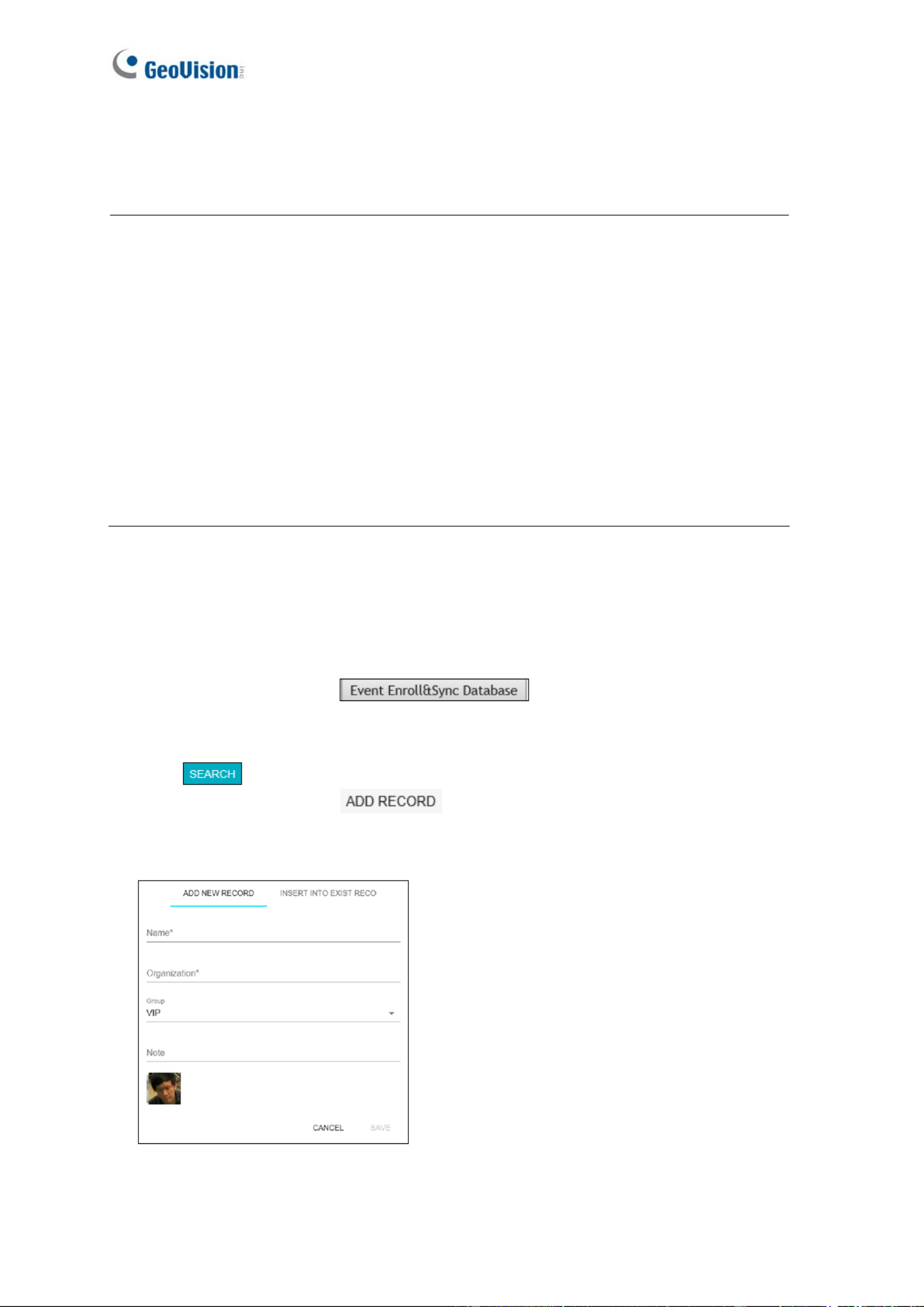
3. Fill out the following information:
Figure 5-10
Name: Type a desired name for the person.
Organization: Type a desired organization name for the person.
Group: Select from a list of three groups in which the person shall be categorized
under. The three groups include VIP, Normal, Unwelcomed. To add more groups,
see [Group Management], 5.6.1 Settings.
Note: Type any additional remarks.
Browse: Click to add portrait photos or snapshots, as face recognition data, for the
person. Make sure the photos meet all the requirements as specified in 5.5.1 Photo
Requirements.
4. Click Save to save the face data. If the photos selected don’t meet the required criteria,
an error message will appear.
5. To add photos to or edit an existing profile, click the Edit Record icon in Figure 5-9.
68
Note:
1. The group settings can be used to trigger output alarms on the camera, and on the VMS
through a GV-I/O Box. For related settings, see 5.6.5 Trigger Area in the manual and
Configuring Face Setting, Chapter 3, GV-VMS User’s Manual respectively.
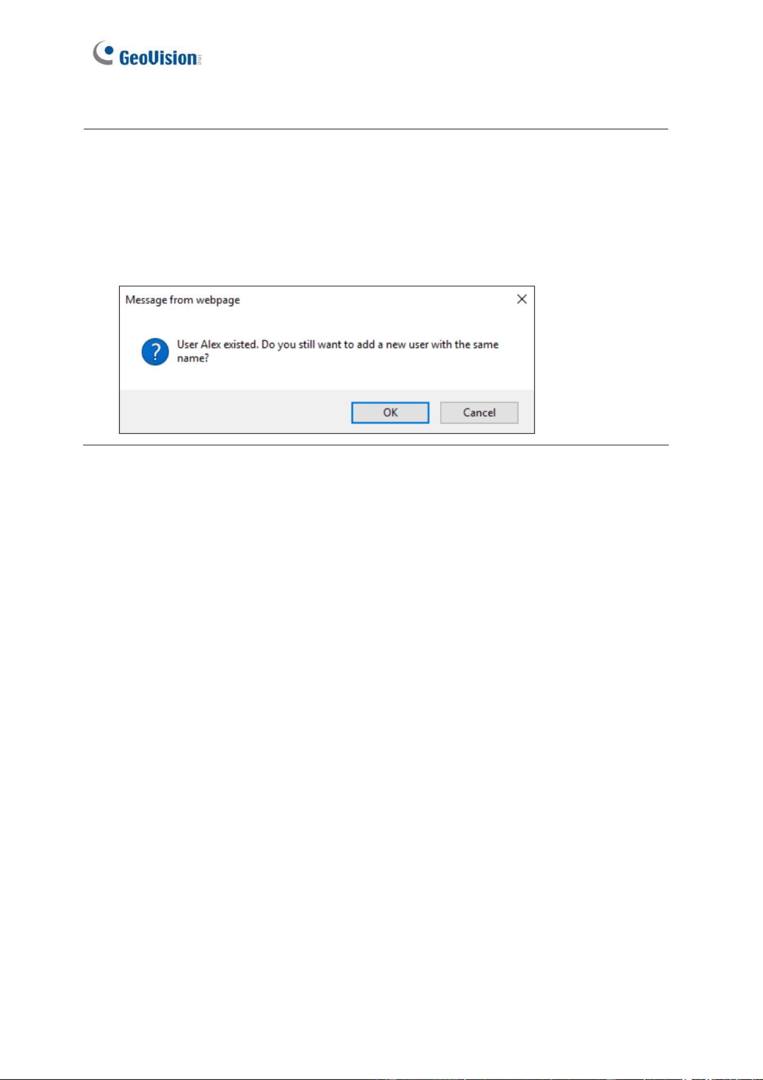
2. It is possible to create two face data with identical names in the database. In this case,
simply click OK when you are prompted by the pop-up message.
69
Face Recongition
5
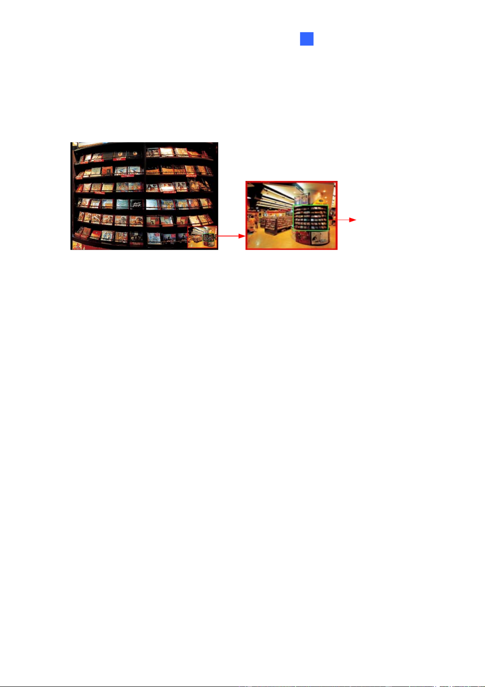
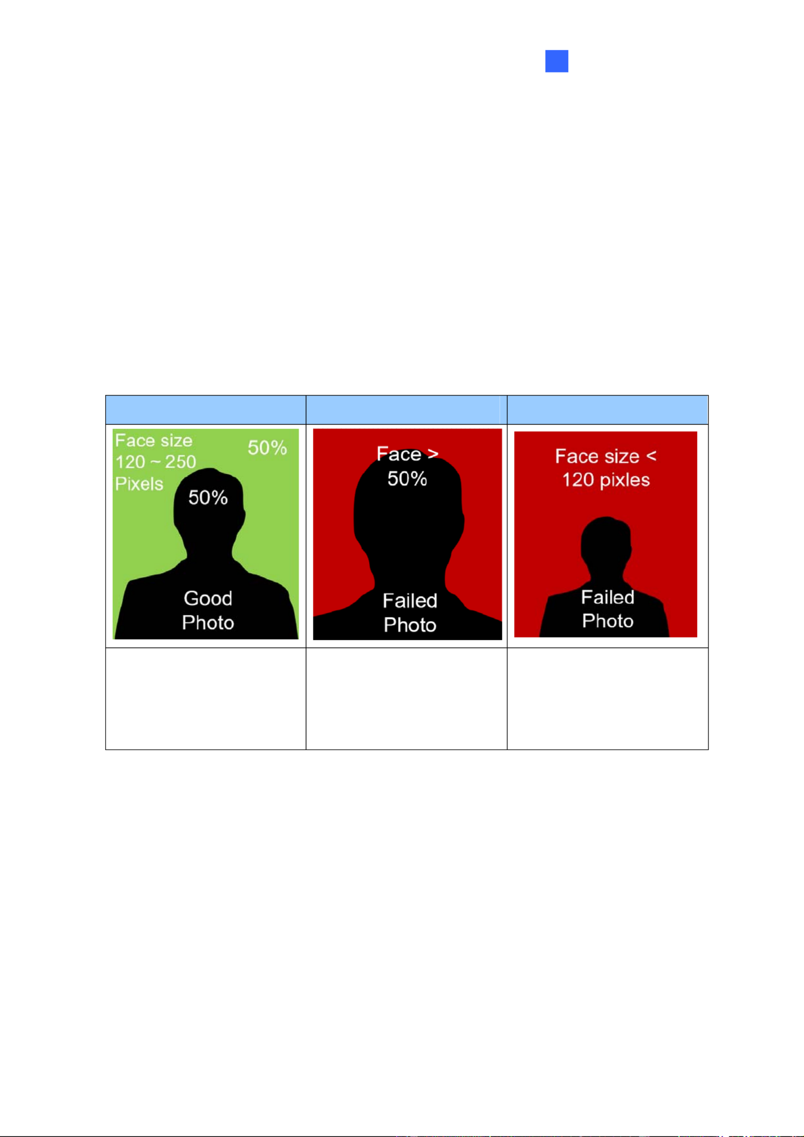
5.5.1 Photo Requirements
For face recognition to work, it is required for the photos to meet the following criteria:
Each photo should consist of only one face.
Size of the face in the photo is around 120 ~ 150 pixels.
The file size of the photo cannot exceed 350 KB.
Only JPG / JPEG format is supported.
Make sure the face of the person does not occupy more than 50% of the image.
See the examples below:
Best Example Example of Failure - 1 Example of Failure - 2
The face occupies 50% of
the image. The size of the
person’s face is around
120 ~150 pixels.
The face occupies more
than 50% of the image.
The size of the person’s
face is less than 120 pixels.
Figure 5-11
The accuracy of the face recognition can be improved by conforming to the suggestions
below:
Enroll 5 or more photos for each person with different angles
Make sure the lighting is sufficient to reduce shadows on faces.
Avoid glare from the glasses that obscures the eyes.
Take the photo of the person from a distance of about 1 ~ 1.5 meters (3.2 ~ 4.9 feet)
away from the camera to minimize image distortions.
70

More photos with different variations and under different lighting conditions can increase the
recognition performance. It is recommended to include at least a front view (close view
and distant view), a tilted-left view, a tilted-right view, and a 20 degree view from above
view per face ID.
Front View
(Close View)
Front View
(Distant View)
Tilted-Left
View
Tilted-Right
View
20 Degree View
from above
view
Figure 5-12
See the table below for more examples. You can enroll a maximum of 20 photos per Face ID.
Smiling View Glasses
Removed view
20 Degree View
from below
Internal IR LED
(with Glasses)
Internal IR LED
(Glasses
Removed)
Figure 5-13
Note: You can take the portraits with different sources of light, such as IR LED, WDR or
Back Light Compensation.
Certain articles and / or angle of view may pose limitations to the accuracy of face recognition.
See Appendix B. Limitations to Face Recognition to avoid them if the recognition results are
still ineffective.
71

Face Recongition
5
Using Snapshots
If for any reason standard portrait photos cannot be taken, you can increase the recognition
performance by using snapshots taken from the surveillance site. Possible scenarios may
include:
Nighttime Recognition: where the installation site may not be subjected to IR LED
enrollment conveniently.
Special Entities: who are unwelcomed or who refuse to comply with the standard
enrollment process.
Frequently Misrecognized Entities: whose personal photos were not taken properly,
which leads to deficient recognition results.
To use snapshots from live videos, see 3.3 Snapshot of a Live Video.
To use snapshots from recorded videos, see 3.4 Video Recording. Capture the desired
image and use it as the source for face data enrollment.
To use snapshots from events, go to Event and Alerts and click Events. Right-click the
snapshot under Image (Snapshot of Events, Figure 5-17) and click Save image as… to save
the cropped image as the future source for face data enrollment. See 5.6.4 Events.
After the snapshots are saved, edit them so that they meet the requirements as specified in
5.5.1 Photo Requirements.
72
5.6 Face Recognition Basic Settings
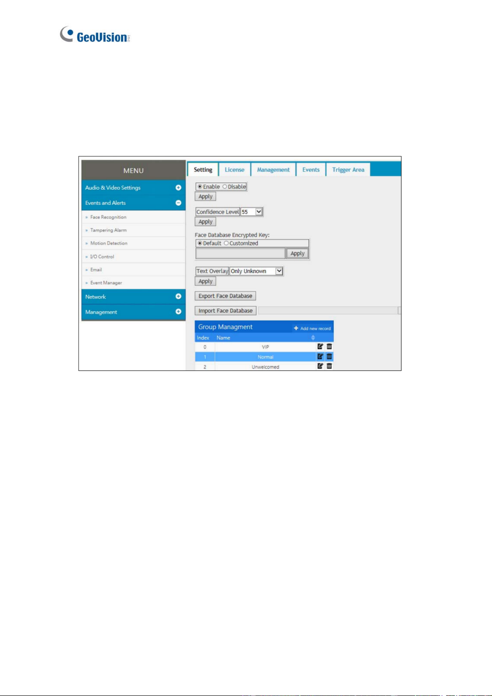
5.6.1 Settings
After the camera is installed, select Enable to activate face recognition and click Apply.
Figure 5-14
[Confidence Level] Select the confidence level for different precision requirements.
At level 50, the camera identifies similar faces from the face database when a person
passes by.
At level 55, the camera recognizes the passing person with increased accuracy.
At level 60, it is required for the person to be seen directly in front of the camera at a
proper distance with his / her face captured under good lighting condition for the
recognition to work.
[Face Database Encrypted Key] Export and import the database with encryption. Select
Customized and type an encrypted key, with the maximum length of 20 characters containing
letters and/or numbers, to protect the exports with encryption. When importing an encrypted
database, a valid key to be entered in this field is required to open it.
[Text Overlay] Select whether to display face data on the live view, or only display the face
data of recognized (known) persons, or only the text “unknown” for the persons failed to be
recognized.
73
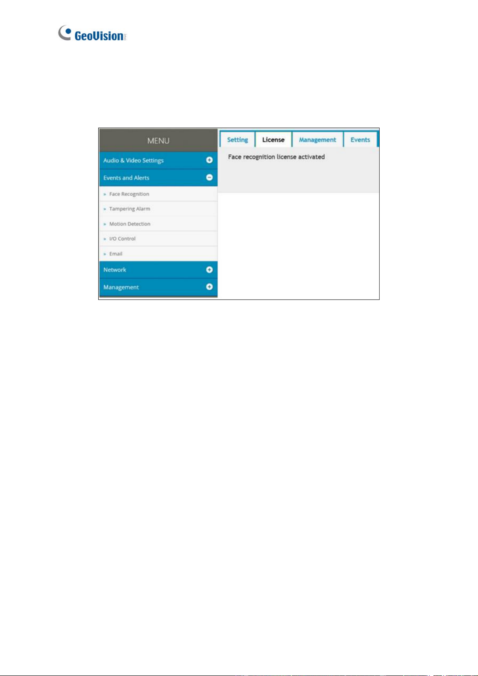
5.6.2 License
The license key is programmed by default. When the license key is programmed properly,
the settings page will show Face recognition license activated.
Figure 5-15
75
Face Recongition
5
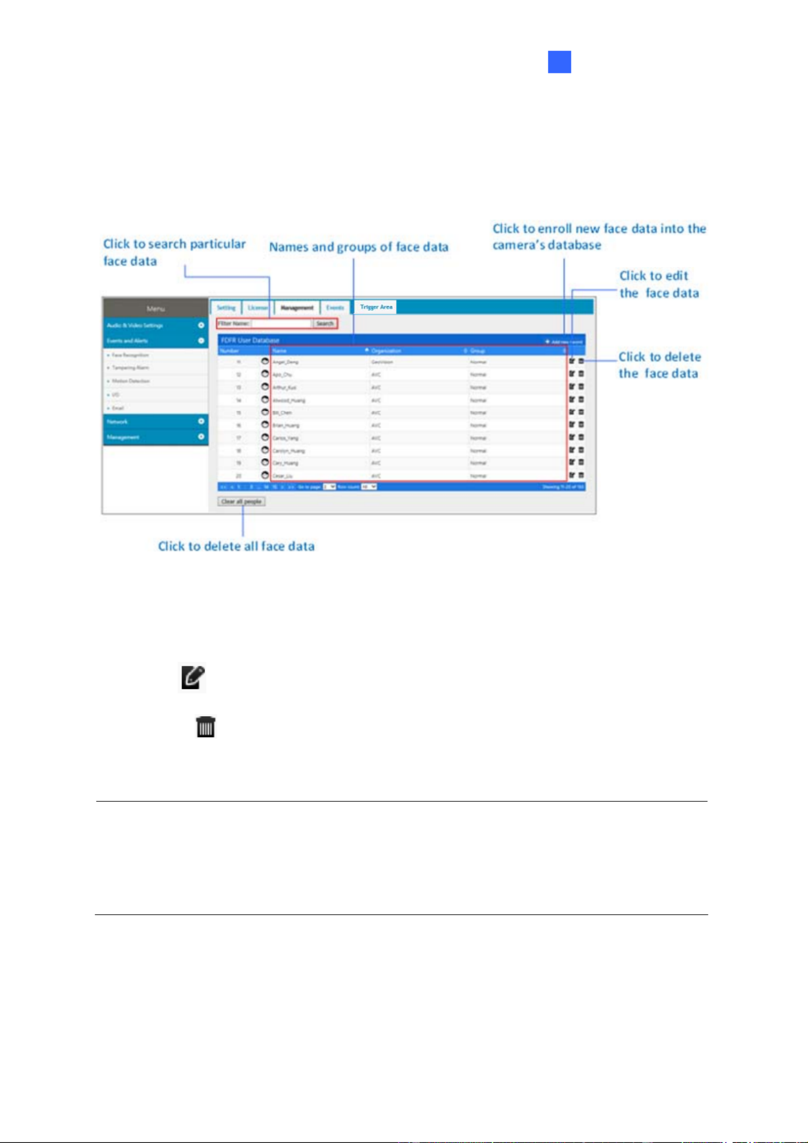
5.6.3 Management
In the Management section, you can enroll, review, search and edit the enrollment data of a
specific entity, including pictures and name.
Figure 5-16
[Filter Name] Type Name and click Search to retrieve the face data of a particular person.
[Add new record] Click to create new face data. See 5.5 Enrolling Face Data.
[Edit] Click to edit the face data. See 5.5 Enrolling Face Data.
[Delete] Click to delete the face data.
[Clear all people] Click to delete all face data in the face database.
Note: When using the Search function, the results will include all entries containing the
keyword searched for, unless further specified. Suppose the face database contains
entries of “Alvin Martin” and “Alvin Huang”, both results are shown when using “Alvin” as
the keyword. When the keyword is further specified as “Alvin Huang”, “Alvin Martin” is
excluded from the search results.
76

5.6.4 Events
In the Events section, you can search the face event log, enroll faces and synchronize with
face databases of other cameras. The camera keeps the events for 7 days or up to 160,000
events. After reaching either the 7 days or the 160,000 events quota, the oldest event is
recycled.
Note: When applying Face Recognition, one camera can only be connected to one
GV-VMS host at a time.
Event Time Snapshot of Event
Closest Match in the
Camera’s database
Second Closest Match in
the Camera’s database
Figure 5-17
5.6.4.1 Searching for log data
1. Specify the Start Time and End Time of the log data.
2. Click Query to display the search results.
3. Choose to display 10 25, , or 50 query entries from the drop-down list.
77

Face Recongition
5
4. To locate specific events, select Advanced Search. The search field appears.
Figure 5-18
Filter Name: Type the name of the person to filter for the person’s recognition
events.
Filter Group: Select among VIP, Normal and Welcomed from the drop-down list to
show the event log of all persons who belong to that group.
Filter Organization: Type the organization to display all events with the members
belonging to that organization.
Filter Confidence Name: Type the name of the person and specify the confidence
interval, from Min Score to Max Score, in which it is searched for. For instance, if
Jack is searched with a Min Score of 0 and Max Score of 1, all results of Jack
recorded under Conf0 to Conf1 will be displayed.
Conf1: The closest match, of Face ID from the database, to the recognition
event.
Conf2: The second-closest match, of Face ID from the database, to the
recognition event.
5. To see the full snapshot of the event, double-click the snapshot under Image. Right-click
the image to save the picture.
Figure 5-19
78
6. To update and show query results periodically, select Auto Polling. Type the time
interval in minutes in the next field. See Figure 5-18.
Note:
1. The actual event time may vary depending on your computer’s clock.
2. When using the Search function, the results will include all entries containing the
keyword searched for, unless further specified. Suppose the face database
contains events related to “Alvin Martin” and “Alvin Huang”, both results are shown
when using “Alvin” as the keyword. When the keyword is further specified as “Alvin
Huang”, “Alvin Martin” is excluded from the search results.
3. The texts and the snapshots of the face events have different recycle thresholds as
they are stored in the camera’s storage space and the memory card respectively.
As a result, some older events may be displayed as text-only events when the
snapshots are removed due to the memory card reaching its 3GB limit while the
event texts are still in place.
5.6.4.2 Enrolling Faces
You can enroll a new face from recognition events or include the new face to an existing face
ID.
1. On the Events page, click to open the Camera Manager page.
2. Specify the Start and End date and time and/or the filtering criteria to locate specific
events. See Step 4 in 5.6.4.1 Search for log data.
3. Click to display the search results.
4. To enroll a new face, click at the right side of every entry. The following
dialog box appears, which functions are similar to those of Step 3 in 5.5 Enrolling Face
Data.
Figure 5-20
79

Face Recongition
5
5. To insert the new face into an existing record, click INSERT INTO EXIST REC at the top
bar to open the following dialog box and search the name for the face.
Figure 5-21
5.6.4.3 Synchronizing Face Databases
You can synchronize the face databases of more than one camera.
1. On the Events page, click to open the Camera Manager
page.
2. Click SYNC DATABASE at the top bar to open the following dialog box.
Figure 5-22
3. To add a camera, click , type its IP Address, Username and Password and
click Save.
4. Select the desired camera(s) and click UPLOAD DATABASE to upload the current face
database into the selected camera(s). When the uploading process is complete, a
successful message will be shown.
80
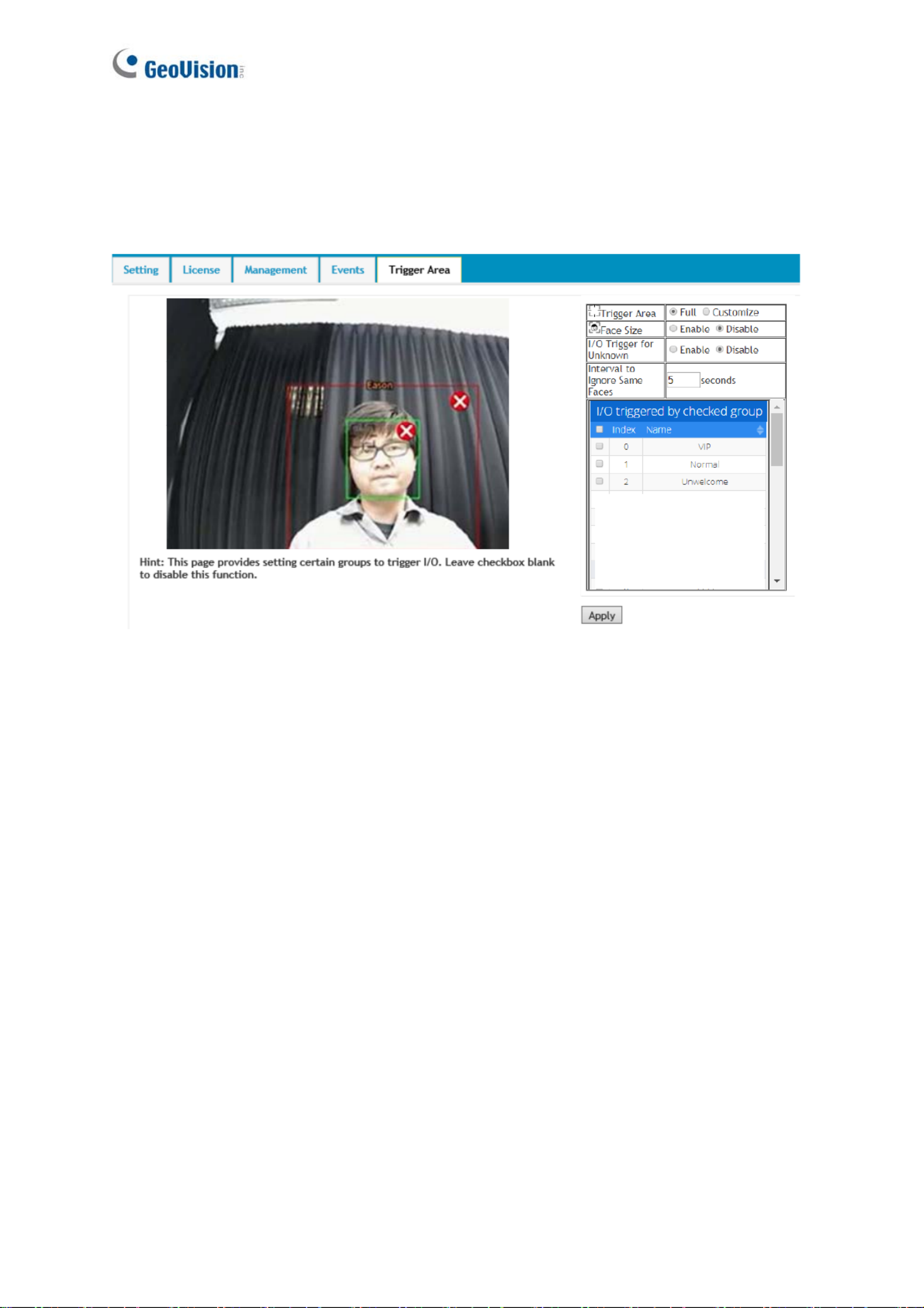
81
5.6.5 Trigger Area
You can specify an area of interest to trigger face recognition, and an output device if a person
from the selected groups appears on the live view and/or if the person fails to be recognized
from the database.
Figure 5-23
[Trigger Area] Select Full to fill the entire screen or select Customize to define an area of
interest to trigger face recognition and/or an output device.
[Face Size] Select Enable to draw an area corresponding to the size of a face. The area
outlined must be smaller than the face detected for a triggering action.
[I/O Trigger for Unknown] Trigger the output device when a person fails to be recognized
from the database.
[Interval to Ignore Same Faces] Specify the time interval to prevent the output device from
being triggered again if the same face is detected on the live view.
[I/O triggered by checked group] Select the face groups to be detected to trigger the output
device.

Recording and Playback
6
Chapter 6 Recording and Playback
The camera can only record video and audio to the camera’s memory card upon
disconnecting from GV-DVR / NVR / VMS. To do so, make sure that the micro-SD card is
inserted into the memory card slot (No.15, Figure 1-2), formatted (see 4.4.4 External Storage)
and enable the Disconnection Record function. For details, see 4.4.3 Tools. To set up
audio recording, see 4.1.2 Audio Settings.
6.1 Playback Using the Memory Card
You can access the recordings from your local PC by connecting the memory card to a
memory card reader. Since the video files are saved in the MPEG4 format, they are
accessible by any video player that supports the format. See 4.4.4 External Storage to
remove the micro-SD card safely.
82

Chapter 7 Advanced Applications
This chapter introduces advanced applications.
7.1 Upgrading System Firmware
GeoVision periodically updates the latest firmware to the company website. You can update
the camera’s firmware through the Web interface or GV-IP Device Utility.
7.1.1 Using the Web Interface
1. On the top bar, go to System Settings. Under Management, select Tools and click
Firmware Upgrade.
Figure 7-1
2. Click the Browse button to locate the firmware file (.zip) saved at your local computer.
3. Click the Upload button to start upgrading.
83
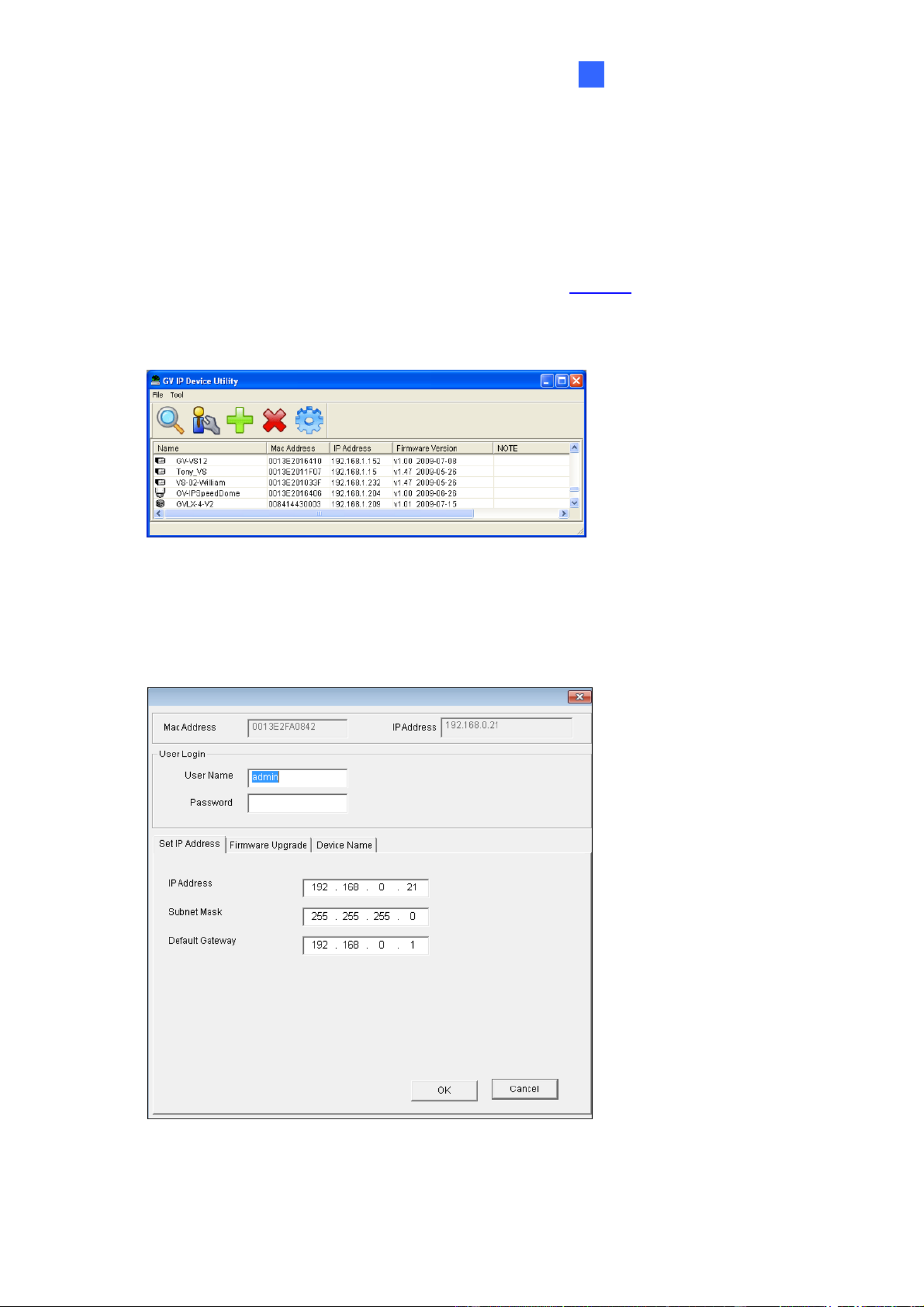
Advanced Applications
7
7.1.2 Using the GV-IP Device Utility
The IP Device Utility provides another way to upgrade the firmware. Note the computer used
to upgrade firmware must be under the network of the camera.
1. Download and install the GV-IP Device Utility from our Website.
2. Double-click the GV-IP Device Utility icon created on your desktop. This dialog box
appears.
Figure 7-2
3. Click the Search button to locate the available camera on the same LAN. Or click the
New button and assign the IP address to locate the camera on the Internet.
4. Double-click the camera in the list. This dialog box appears.
Figure 7-3
84

5. Click the Firmware Upgrade tab. This dialog box appears.
Figure 7-4
6. Click the Browse button to locate the firmware file (.img) saved at your local computer.
7. Type Password, and click Upgrade to start the upgrade.
85

Advanced Applications
86
7
7.2 Restoring to Factory Default Settings
If for any reason the camera is not responding correctly, you can reset it to its factory default
setting by using the camera’s Web interface or by operating directly on the camera.
7.2.1 Using the Web Interface
1. On the Web interface, go to System Settings.
2. In the left menu of Web interface, select Management and click Tools.
3. Under the Device Settings tab, click the Default button to restore the factory default
settings, and the current IP address of the camera will be kept.
4. To restore the camera and its IP address to factory default settings, select Restore All
Default Setting Without Keeping Current IP Address and click Default.
7.2.2 Directly on the Camera
1. Keep the power and network cables (or PoE) connected to the camera.
2. Press and hold the Default button on the camera body. The status LED blinks. This
shall take about 8 seconds.
Default button
Figure 7-5
3. Release the Default button when the status LED stops blinking. The process of loading
default settings is completed and the camera reboots automatically.

Chapter 8 DVR / NVR / VMS Configurations
The GV-DVR / NVR / VMS provide a full range of video management functions and features,
such as video viewing, recording, playback, alert settings and more. The following are the
integration specifications:
For GV-VD8700, GV-DVR / NVR version 8.7.4.0, GV-VMS version 17.1 or later
versions are required. For GV-FD8700-FR, GV-DVR / NVR version 8.8.0, GV-VMS
version 17.1.0.100 or later versions are required.
Face Recognition is only supported by GV-VMS. When applying Face Recognition,
one camera can only be connected to one GV-VMS at a time. See Configuring Face
Setting, Chapter 3, GV-VMS User’s Manual.
The camera supports up to 8 streams of connection.
When the camera is connected to IE browser or GeoVision CMS applications, it takes
up 1 stream when it is connected to GV-DVR / NVR / VMS, it takes up 2 streams.
Note: By default, the camera is in dual streams and will take up 2 streams when
connected to GV-DVR / NVR / VMS.
Figure 8-1
87
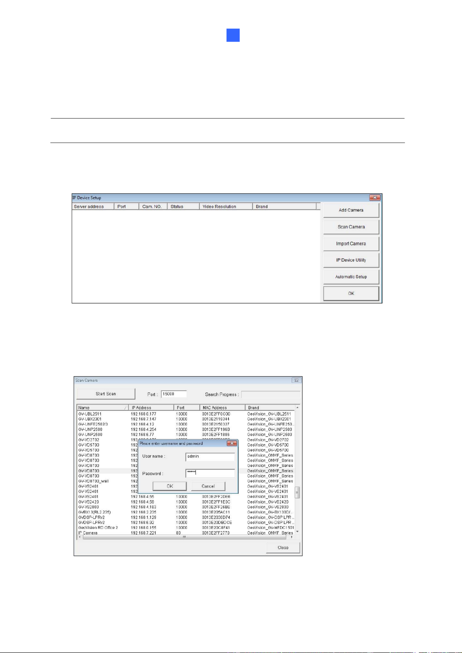
DVR / NVR / VMS Configurations
8
8.1 Setting Up IP Cameras on GV-DVR / NVR
Follow the steps below to manually connect your camera to GV-DVR / NVR.
Note: The following instructions are based on GV-DVR / NVR V8.7.4.0 software and user
interfaces.
1. On the GV-DVR / NVR’s main screen, click the Configure button, select System
Configure, select Camera Install and click IP Camera Install. This dialog box appears.
Figure 8-2
2. To automatically set up an IP camera, click Scan Camera to detect any IP cameras on
the same LAN.
3. Double-click the camera and type its user name and password.
Figure 8-3
88

4. Click OK. This dialog box appears.
Figure 8-4
5. Click OK to add the camera to the connection list.
6. Click the listed camera and select Display position to map the IP camera to channel on
the GV-DVR / NVR.
Figure 8-5
7. The Status column now should display “Connected”. Click OK. The dome view is
displayed on the selected channel of GV-DVR / NVR.
89

DVR / NVR / VMS Configurations
8
8.1.1 Customizing Camera Settings on GV-DVR / NVR
After the camera is connected and assigned with a display channel, you can configure the
camera’s settings such as frame rate, codec type and resolution. Right-click the camera to
see the following list of options:
Figure 8-6
Disconnect camera: Ends the connection to the GV-IP camera. You can change the
settings of the camera after the camera is disconnected.
Change Position: Changes the grid position where the live view is displayed on the main
screen.
Delete camera: Delete the camera on the camera list.
Remote Camera Settings: Accesses the Web interface.
Network Time Out: When network disconnection exceeds the specified time period, the
camera status will be displayed as Connection Lost.
On Demand Display: When the camera supports dual streaming with different
resolutions, select On Demand Display to enable automatic adjustment of live view
resolution.
Live-view frame rate control (Sub stream): Sets the live view frame rate of the sub
stream to help reduce the CPU usage. Select one of the following options when the live
view codec of the camera is set to H.264 or H.265:
Maximum Live-view Frame Rate: Views the video at the maximum frame rate
possible.
Live-view Key Frame only: You can choose to view the key frames of the videos
only instead of all frames on the live view. This option is related to the GOP setting of
the IP camera. For example, if the GOP value is set to 30, there is only one key
frame among 30 frames.
90

Live-view frame rate control (Main stream): Sets the live view frame rate of the main
stream with higher resolution when On Demand function is enabled. Refer to Live-view
frame rate control above to see the options available.
Frames to keep in live view buffer: Specifies the number of frames to keep in the live
view buffer.
Recording Codec Format: Specifies whether to record in standard or GeoVision type of
H.264 / H.265 codec.
ONVIF Settings: Adjusts the camera’s video settings when connecting through ONVIF
protocol. See 8.1 Setting Up IP Cameras on GV-DVR / NVR.
91
Produktspezifikationen
| Marke: | GeoVision |
| Kategorie: | Überwachungskamera |
| Modell: | GV-VD8700 |
Brauchst du Hilfe?
Wenn Sie Hilfe mit GeoVision GV-VD8700 benötigen, stellen Sie unten eine Frage und andere Benutzer werden Ihnen antworten
Bedienungsanleitung Überwachungskamera GeoVision

28 August 2024
28 August 2024
28 August 2024
28 August 2024
28 August 2024
28 August 2024
28 August 2024
28 August 2024
28 August 2024
28 August 2024
Bedienungsanleitung Überwachungskamera
- Überwachungskamera Samsung
- Überwachungskamera Approx
- Überwachungskamera Belkin
- Überwachungskamera Sanyo
- Überwachungskamera Exibel
- Überwachungskamera Gembird
- Überwachungskamera Genius
- Überwachungskamera Hama
- Überwachungskamera LogiLink
- Überwachungskamera Logitech
- Überwachungskamera Manhattan
- Überwachungskamera Nedis
- Überwachungskamera Niceboy
- Überwachungskamera Philips
- Überwachungskamera Sony
- Überwachungskamera Trust
- Überwachungskamera Panasonic
- Überwachungskamera Clas Ohlson
- Überwachungskamera Profile
- Überwachungskamera ZyXEL
- Überwachungskamera Bosch
- Überwachungskamera Laserliner
- Überwachungskamera Buffalo
- Überwachungskamera Canon
- Überwachungskamera Velleman
- Überwachungskamera Powerfix
- Überwachungskamera Eminent
- Überwachungskamera Linksys
- Überwachungskamera Maginon
- Überwachungskamera Netgear
- Überwachungskamera Technaxx
- Überwachungskamera Alecto
- Überwachungskamera Denver
- Überwachungskamera EMOS
- Überwachungskamera Gira
- Überwachungskamera König
- Überwachungskamera MarQuant
- Überwachungskamera Renkforce
- Überwachungskamera Thomson
- Überwachungskamera Trevi
- Überwachungskamera Blaupunkt
- Überwachungskamera Schneider
- Überwachungskamera Trebs
- Überwachungskamera Pyle
- Überwachungskamera Topcom
- Überwachungskamera Pioneer
- Überwachungskamera JVC
- Überwachungskamera Motorola
- Überwachungskamera Xiaomi
- Überwachungskamera Abus
- Überwachungskamera Avidsen
- Überwachungskamera Elro
- Überwachungskamera EZVIZ
- Überwachungskamera Imou
- Überwachungskamera INSTAR
- Überwachungskamera Megasat
- Überwachungskamera Olympia
- Überwachungskamera Smartwares
- Überwachungskamera Switel
- Überwachungskamera Yale
- Überwachungskamera Ferguson
- Überwachungskamera Orion
- Überwachungskamera Gigaset
- Überwachungskamera Strong
- Überwachungskamera Toshiba
- Überwachungskamera Garmin
- Überwachungskamera Perel
- Überwachungskamera Netis
- Überwachungskamera Lindy
- Überwachungskamera Fenton
- Überwachungskamera Waeco
- Überwachungskamera Acme
- Überwachungskamera Burg Wächter
- Überwachungskamera Marmitek
- Überwachungskamera Marshall
- Überwachungskamera Honeywell
- Überwachungskamera B/R/K
- Überwachungskamera Marshall Electronics
- Überwachungskamera TRENDnet
- Überwachungskamera Targa
- Überwachungskamera First Alert
- Überwachungskamera AVerMedia
- Überwachungskamera Zebra
- Überwachungskamera TP-Link
- Überwachungskamera Flamingo
- Überwachungskamera Kodak
- Überwachungskamera Rollei
- Überwachungskamera IGet
- Überwachungskamera Adj
- Überwachungskamera Netatmo
- Überwachungskamera Duramaxx
- Überwachungskamera Ebode
- Überwachungskamera Xavax
- Überwachungskamera InFocus
- Überwachungskamera Overmax
- Überwachungskamera Monoprice
- Überwachungskamera Monacor
- Überwachungskamera JUNG
- Überwachungskamera Ednet
- Überwachungskamera AG Neovo
- Überwachungskamera Nest
- Überwachungskamera Edimax
- Überwachungskamera V-TAC
- Überwachungskamera Aritech
- Überwachungskamera Uniden
- Überwachungskamera Kogan
- Überwachungskamera Genie
- Überwachungskamera M-e
- Überwachungskamera Elmo
- Überwachungskamera Lumens
- Überwachungskamera Jablocom
- Überwachungskamera Conceptronic
- Überwachungskamera D-Link
- Überwachungskamera Eufy
- Überwachungskamera Stabo
- Überwachungskamera Friedland
- Überwachungskamera EVOLVEO
- Überwachungskamera SPC
- Überwachungskamera August
- Überwachungskamera Ring
- Überwachungskamera Digitus
- Überwachungskamera SereneLife
- Überwachungskamera Swann
- Überwachungskamera Vitek
- Überwachungskamera DataVideo
- Überwachungskamera LevelOne
- Überwachungskamera Aida
- Überwachungskamera APC
- Überwachungskamera Beafon
- Überwachungskamera Chuango
- Überwachungskamera Cisco
- Überwachungskamera Grandstream
- Überwachungskamera Delta Dore
- Überwachungskamera EVE
- Überwachungskamera Defender
- Überwachungskamera Tenda
- Überwachungskamera Swisstone
- Überwachungskamera Foscam
- Überwachungskamera Ubiquiti Networks
- Überwachungskamera Kramer
- Überwachungskamera Vaddio
- Überwachungskamera Intellinet
- Überwachungskamera Reolink
- Überwachungskamera Swan
- Überwachungskamera Hikvision
- Überwachungskamera FLIR
- Überwachungskamera Furrion
- Überwachungskamera Arlo
- Überwachungskamera Nexxt
- Überwachungskamera Planet
- Überwachungskamera EnGenius
- Überwachungskamera Dörr
- Überwachungskamera Lorex
- Überwachungskamera Ikan
- Überwachungskamera Comtrend
- Überwachungskamera Somfy
- Überwachungskamera Dahua
- Überwachungskamera Dedicated Micros
- Überwachungskamera DIO
- Überwachungskamera EasyN
- Überwachungskamera Escam
- Überwachungskamera EverFocus
- Überwachungskamera Ganz
- Überwachungskamera Hombli
- Überwachungskamera Home Protector
- Überwachungskamera Iiquu
- Überwachungskamera Indexa
- Überwachungskamera Interlogix
- Überwachungskamera KlikaanKlikuit
- Überwachungskamera Kompernass
- Überwachungskamera Mr Safe
- Überwachungskamera Naxa
- Überwachungskamera Nordval
- Überwachungskamera Notifier
- Überwachungskamera Oplink
- Überwachungskamera Provision ISR
- Überwachungskamera Quantum
- Überwachungskamera Raymarine
- Überwachungskamera Revo
- Überwachungskamera SAB
- Überwachungskamera Satel
- Überwachungskamera SecurityMan
- Überwachungskamera Sinji
- Überwachungskamera SMC
- Überwachungskamera Sonic Alert
- Überwachungskamera Sricam
- Überwachungskamera Steren
- Überwachungskamera Storage Options
- Überwachungskamera Tenvis
- Überwachungskamera Hive
- Überwachungskamera Ubiquiti
- Überwachungskamera Vivotek
- Überwachungskamera Woonveilig
- Überwachungskamera Y-cam
- Überwachungskamera ACTi
- Überwachungskamera AVer
- Überwachungskamera Epcom
- Überwachungskamera ZKTeco
- Überwachungskamera AirLive
- Überwachungskamera Mobotix
- Überwachungskamera Dahua Technology
- Überwachungskamera Speco Technologies
- Überwachungskamera 3xLOGIC
- Überwachungskamera Atlantis Land
- Überwachungskamera CRUX
- Überwachungskamera Pentatech
- Überwachungskamera Summer Infant
- Überwachungskamera Illustra
- Überwachungskamera Surveon
- Überwachungskamera Avigilon
- Überwachungskamera Brilliant
- Überwachungskamera Hanwha
- Überwachungskamera Lanberg
- Überwachungskamera Verint
- Überwachungskamera Axis
- Überwachungskamera EtiamPro
- Überwachungskamera MEE Audio
- Überwachungskamera Advantech
- Überwachungskamera Chacon
- Überwachungskamera Alula
- Überwachungskamera EKO
- Überwachungskamera IOIO
- Überwachungskamera KJB Security Products
- Überwachungskamera BZBGear
- Überwachungskamera Adesso
- Überwachungskamera Brickcom
- Überwachungskamera Insteon
- Überwachungskamera Aigis
- Überwachungskamera Pelco
- Überwachungskamera ORNO
- Überwachungskamera Atlona
- Überwachungskamera Linear PRO Access
- Überwachungskamera Laxihub
- Überwachungskamera Valueline
- Überwachungskamera Aqara
- Überwachungskamera Tecno
- Überwachungskamera Lutec
- Überwachungskamera Brinno
- Überwachungskamera Night Owl
- Überwachungskamera WyreStorm
- Überwachungskamera Exacq
- Überwachungskamera Equip
- Überwachungskamera AVMATRIX
- Überwachungskamera UniView
- Überwachungskamera Alfatron
- Überwachungskamera Syscom
- Überwachungskamera BLOW
- Überwachungskamera Videotec
- Überwachungskamera DSC
- Überwachungskamera AViPAS
- Überwachungskamera Milestone Systems
- Überwachungskamera Inkovideo
- Überwachungskamera Hamlet
- Überwachungskamera Mobi
- Überwachungskamera Infortrend
- Überwachungskamera VideoComm
- Überwachungskamera Kguard
- Überwachungskamera Boyo
- Überwachungskamera HiLook
- Überwachungskamera Mach Power
- Überwachungskamera Canyon
- Überwachungskamera Digital Watchdog
- Überwachungskamera Ernitec
- Überwachungskamera Ikegami
- Überwachungskamera Gewiss
- Überwachungskamera Weldex
- Überwachungskamera Costar
- Überwachungskamera Sentry360
- Überwachungskamera ALC
- Überwachungskamera Spyclops
- Überwachungskamera Compro
- Überwachungskamera IDIS
- Überwachungskamera I3International
- Überwachungskamera B & S Technology
- Überwachungskamera Qian
- Überwachungskamera Accsoon
- Überwachungskamera Control4
- Überwachungskamera Petcube
- Überwachungskamera Apeman
- Überwachungskamera ATN
- Überwachungskamera IC Intracom
- Überwachungskamera POSline
- Überwachungskamera Watec
- Überwachungskamera ETiger
- Überwachungskamera Videcon
- Überwachungskamera BirdDog
- Überwachungskamera Topica
- Überwachungskamera Rostra
- Überwachungskamera Caddx
- Überwachungskamera Whistler
- Überwachungskamera ClearView
- Überwachungskamera Beseye
- Überwachungskamera IMILAB
- Überwachungskamera CNB Technology
- Überwachungskamera Tapo
- Überwachungskamera Securetech
- Überwachungskamera NetMedia
- Überwachungskamera Nivian
- Überwachungskamera Guardzilla
- Überwachungskamera Blink
- Überwachungskamera Zavio
- Überwachungskamera Campark
- Überwachungskamera IPX
- Überwachungskamera Annke
- Überwachungskamera AVTech
- Überwachungskamera Vimtag
- Überwachungskamera Security Labs
- Überwachungskamera Seneca
- Überwachungskamera Vosker
- Überwachungskamera Owltron
- Überwachungskamera Enabot
- Überwachungskamera Luis Energy
- Überwachungskamera Sir Gawain
- Überwachungskamera VisorTech
- Überwachungskamera Milesight
- Überwachungskamera GVI Security
- Überwachungskamera Conbrov
- Überwachungskamera HuddleCamHD
- Überwachungskamera Setti+
- Überwachungskamera BIRDFY
- Überwachungskamera I-PRO
- Überwachungskamera DVDO
- Überwachungskamera TCP
Neueste Bedienungsanleitung für -Kategorien-
15 Oktober 2024

15 Oktober 2024
14 Oktober 2024
14 Oktober 2024

13 Oktober 2024
13 Oktober 2024
13 Oktober 2024
11 Oktober 2024
11 Oktober 2024
11 Oktober 2024