Festo VPEV-1/8-M12 Bedienungsanleitung
Festo Nicht kategorisiert VPEV-1/8-M12
Lies die bedienungsanleitung für Festo VPEV-1/8-M12 (2 Seiten) kostenlos online; sie gehört zur Kategorie Nicht kategorisiert. Dieses Handbuch wurde von 53 Personen als hilfreich bewertet und erhielt im Schnitt 5.0 Sterne aus 3 Bewertungen. Hast du eine Frage zu Festo VPEV-1/8-M12 oder möchtest du andere Nutzer dieses Produkts befragen? Stelle eine Frage
Seite 1/2
VPEV-x-M12
Festo S
E & Co. KG
Postfach
73726 Esslingen
+49 711 347-0
www.festo.com
Bedienungsanleitung
Operating instructions
操指南
8048534
1509c
[8048535]
Original: de
Zur Einhaltung der Zertifizierungsbedingungen von
Underwriters Laboratories Inc. (UL) beachten Sie fol
gende englischsprachige Hinweise für USA und Kanada:
To ensure compliance with the Underwriters Labora
tories Inc. (UL) approval conditions for USA and Canada,
please note the following notices in English:
Only for use in Class 2 Circuits.
This device is intended to be used with a Class 2 power
source or NEC Class 2 transformer in accordance with
UL1310 or UL1585.
As an alternative a LV/C (Limited Voltage / Current)
power source with one of the following properties can
be used:
–An isolating device such that the maximum open
circuit voltage potential available to the circuit is not
more than 30 Vac or 42.2 Vdc and the current is
limited to a value not exceeding 8 amperes measured
after 1 minute of operation.
–A suitable isolating source in conjunction with a fuse
in accordance with UL248. The fuse shall be rated
max. 3.3 A (ac circuits max. 30 Vac) or 2.3 A (dc cir
cuits max. 42.4 Vdc) and be installed in the 30 Vac or
42.2 Vdc power supply to the device in order to limit
the available current.
Note that, when more than one power supply or
isolating device is used, connection in parallel is not
permitted.
5
4
1
2
3
SW11
8
6
6
7
Fig. 1
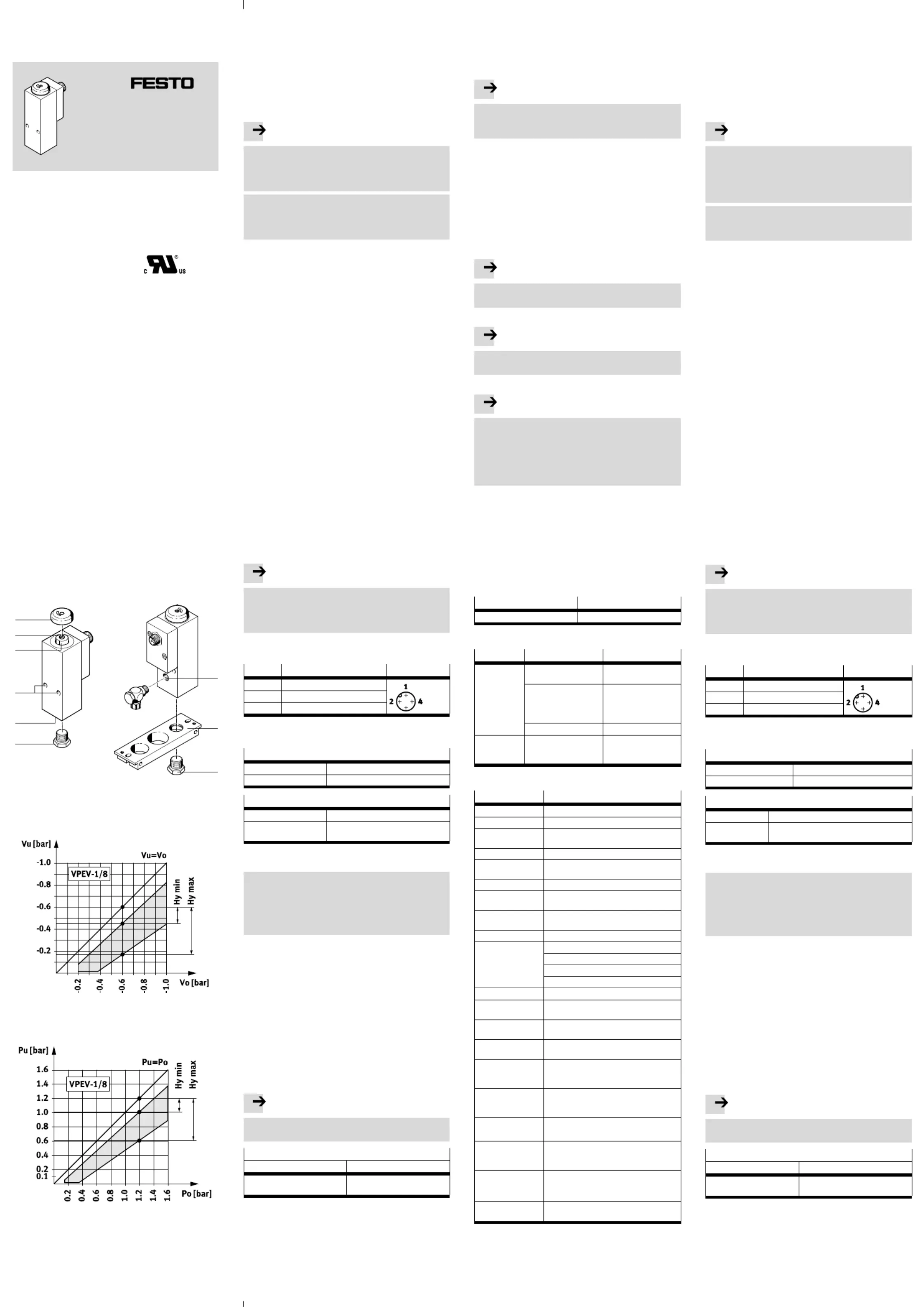
Einstellbereich bei Einsatz als Vakuumschalter
Adjusting range if used as a vacuum switch
Einstellbereich bei Einsatz als Druckschalter
Adjusting range if used as a pressure switch
Fig. 2
Vakuumschalter VPEV-x-M12de.......................
1Anwendung
Der Vakuumschalter VPEV dient bestimmungsgemäß zur
Überwachung von Druckveränderungen im Drucklei
tungssystem. Der VPEV öffnet oder schließt einen elek
trischen Stromkreis beim Erreichen eines einstellbaren
Druckwertes. Die oberen und unteren Schaltpunkte sind
voneinander unabhängig einstellbar.
2Voraussetzungen für den Produkteinsatz
Hinweis
Einbau und Inbetriebnahme nur von qualifiziertem
Fachpersonal, gemäß Bedienungsanleitung. Diese
Produkte sind ausschließlich zur Verwendung mit
Druckluft vorgesehen. Andere Medien auf Anfrage.
Durch unsachgemäße Handhabung entstehen
Fehlfunktionen.
Stellen Sie sicher, dass die Vorgaben dieses
Kapitels stets eingehalten werden.
Vergleichen Sie die Grenzwerte in dieser Bedienungs
anleitung mit denen Ihres Einsatzfalls (z. B. Drücke,
Kräfte, Momente, Temperaturen).
Behalten Sie das einmal gewählte Betriebsmedium
über die gesamte Produktlebensdauer bei.
Entfernen Sie die Verpackungen. Die Verpackungen
sind vorgesehen für eine Verwertung auf stofflicher
Basis (Ausnahme: Ölpapier = Restmüll).
Berücksichtigen Sie die Warnungen und Hinweise
–am Produkt und
–in dieser Bedienungsanleitung.
Verwenden Sie das Produkt im Originalzustand ohne
jegliche eigenmächtige Veränderung.
3Einbau
3.1Mechanisch
Wandbefestigung è Fig. 1
1.Stecken Sie zwei Schrauben M5 durch die Durch
gangsbohrungen 4.
2.Befestigen Sie den VPEV an der vorgesehenen Stelle.
Befestigung mit Montageplatte è Fig. 1
1.Montieren Sie den VPEV mit der Verschlussschraube
6 in den Druckluftanschluss Gx5 an der Montage
platte 7.
3.2Pneumatisch
1.Drehen Sie eine Verschraubung in den Vakuum-
anschluss Gx8. Anziehdrehmoment max. 20 Nm.
2.Verschlauchen Sie die Verschraubung mit einem
entsprechenden Schlauch.
Hinweis
Durch Umsetzen der Verschlussschraube 6 vom
Druckluftanschluss 5 in den Vakuumanschluss 8
kann der VPEV als Druckschalter (Kennlinie è Fig. 2)
eingesetzt werden.
3.3Elektrisch
Verkabeln Sie die Anschlussdose wie folgt:
Pin-Nr.
AnschlüssePin-Belegung
1+ [–]
2Öffner
4Schließer
Max. Anziehdrehmoment 0,5 Nm
4Inbetriebnahme
Werkseinstellung
Unterer Schaltdruck-0,5 bar ±0,04 bar
Hysterese0,3 bar ±0,06 bar
Einstellelemente
Schraube 2Unterer Schaltdruck
Bolzen 3Hysterese (oberer Schaltdruck =
unterer Schaltdruck + Hysterese)
Beachten Sie, dass die Schraube 2 nur beim Drehen
gegen den Uhrzeigersinn einen Anschlag hat.
Definition
Schaltverhalten eines Vakuumschalters è Fig. 2
–oberer Schaltdruck: p1
–unterer Schaltdruck: p2
–Hysterese:Hy
Zur Schaltpunkteinstellung des VPEV è Fig. 1
1.Verkabeln Sie die elektrischen Anschlüsse Pin 1 und
Pin 2 mit einem Durchgangsprüfer;
è Einbau elektrisch.
2.Entfernen Sie die Schutzkappe 1.
3.Drehen Sie die Schraube 2 entgegen dem Uhrzeiger
sinn bis zum Anschlag.
4.Beaufschlagen Sie den VPEV mit dem gewünschten
unteren Schaltdruck p2. Der Durchgangsprüfer geht
in Ausgangsstellung.
5.Drehen Sie die Schraube 2 im Uhrzeigersinn, bis der
VPEV schaltet. Der Durchgangsprüfer reagiert.
Der Schaltpunkt für den unteren Schaltdruck p2 ist
eingestellt.
Hinweis
Eine Umdrehung entspricht einer Veränderung des
Schaltdrucks von ca. 0,18 bar.
Hystereseeinstellung
p1 (-0,6 … -1,0 bar)p1 (-0,2 … -0,6 bar)
Bolzen 3 im Uhrzeigersinn bis
Anschlag drehen.
Bolzen 3gegen den Uhrzeiger
sinn bis Anschlag drehen.
Hystereseeinstellung des VPEV è Fig. 2
6.Drehen Sie den Bolzen 3 im Uhrzeigersinn bis zum
Anschlag. Der Durchgangsprüfer bleibt unverändert.
7.Beaufschlagen Sie den VPEV mit dem oberen Schalt-
druck p1 (unterer Schaltdruck p2 plus gewünschte
Hysterese Hy è Fig. 2). Der Durchgangsprüfer bleibt
unverändert.
8.Drehen Sie den Bolzen 3 gegen den Uhrzeigersinn
bis der VPEV schaltet.
Der Durchgangsprüfer geht in Ausgangsstellung.
Der Schaltpunkt für den oberen Schaltdruck p1 ist
eingestellt.
Bei Bedarf einer Schaltpunktkorrektur:
Hinweis
Beim Drehen an der Schraube 2 nehmen die Schalt
punkte für den oberen und unteren Schaltdruck
gleichzeitig zu oder ab.
9.Wiederholen Sie die nachfolgenden Schritte, bis der
gewünschte obere und untere Schaltpunkt eingestellt
sind:
–zuerst unteren Schaltdruck p2 anlegen und
Schraube 2 drehen, dann
–oberen Schaltdruck p1 anlegen und Bolzen 3
drehen. Dadurch präzisieren Sie schrittweise
Schaltpunkt und Hysterese.
10.Befestigen Sie die Schutzkappe 1.
5Bedienung und Betrieb
Hinweis
Druckänderungen müssen größer als 0,003 bar/s
sein, damit der Vakuumschalter sicher schaltet.
Bei Schwankungen der Mediumstemperatur:
Hinweis
Beachten Sie, dass der Schaltpunkt geringfügig
beeinflusst wird.
Bei Mediumstemperatur 1 °C:
Hinweis
Vermeiden Sie, dass der Taupunkt erreicht wird. Bei
Erreichen des Taupunkts vereist die Membrane und
wird steifer. Dadurch ändern sich die Kennwerte des
Vakuumschalters.
Abhilfe: Der Taupunkt kann durch getrocknete Druck
luft gesenkt werden.
Zum Ausgleich von Schaltpunktabweichungen bei hohen
Schaltspielzahlen:
Wiederholen Sie die Schaltpunkteinstellung
(è Inbetriebnahme).
6Wartung und Pflege
Reinigen Sie bei Bedarf den VPEV außen mit einem
weichen Lappen. Zulässige Reinigungsmedien sind
alle werkstoffschonenden Medien.
7Zubehör
Bezeichnung
Typ
MontageplatteAPL-2N-VPEV
8Störungsbeseitigung
StörungMögliche UrsacheAbhilfe
VPEV schaltet
nicht
Schaltpunkt zu hochSchaltpunkt korrigieren
(è
Inbetriebnahme)
Hysterese zu großHysterese bei Inbetrieb
nahme zunächst auf
Minimum einstellen
(è
Inbetriebnahme)
Schalter defektVPEV zu Festo schicken
Schaltsignal
wird nicht
ausgegeben
AnschlussfehlerÜberprüfen Sie die
elektrische Anschluss
belegung des VPEV
9Technische Daten
TypVPEV-x-M12
MessverfahrenPneumatisch-elektrischer Druckwandler
MessgrößeRelativdruck
Schaltelement
funktion
Wechsler
Betriebsdruck-1 … 1,6 bar
BetriebsmediumVakuum / gefilterte Druckluft, geölt oder
ungeölt, Filterfeinheit min. 40 μm
EinbaulageBeliebig
Pneumatischer An
schluss
Gx
Elektrischer An
schluss
Stecker M12x1, 4-polig, runde Bauform
nach EN 60947-5-2
Druckmessbereich-1 … 1,6 bar
Einstellbereich
Schwellwerte
Vakuum Schaltpunkt: -0,95 … -0,2 bar
Vakuum Hysterese: 0,16 … 0,55 bar
Druckluft Schaltpunkt: 0,16 … 1,6 bar
Druckluft Hysterese: 0,2 … 0,7 bar
Mediumstemperatur-20 … +80 °C
Umgebungs
temperatur
-20 … +80 °C
Max. Schaltaus
gangsspannung AC
48 V
Max. Schaltaus
gangsspannung DC
48 V
Max. Schaltstrom5 A (ohmsche Last)
(Bemessungsbetriebsstrom:
4 A ohmsche Last; 3 A induktive Last)
Mindestlaststrom1 mA (DC/AC 24 V)
10 mA (DC/AC 10 V)
100 mA (DC/AC 5 V)
Zul. Kontakt-
belastung
–Ohmsche Last:DC 30 V5 A
–Induktive Last:DC 30 V 3 A
GebrauchskategorieAC 12/DC 12 (ohmsche Last)
AC 14/DC 13 (kleine elektromagnetische
Last und Elektromagnete)
Schaltzeit:
–bei -0,8 bar
Ein: 8 ms (typisch), Aus: 9 ms (typisch)
–bei 1,6 barEin: 3 ms (typisch), Aus: 7 ms (typisch)
Schutzart nach
EN 60529
IP65
Vacuum switch VPEV-x-M12en........................
1Application
The vacuum switch VPEV has been designed for monitor
ing changes in pressure in the compressed air system.
The VPEV opens or closes an electrical circuit when an
adjustable pressure value is reached. The upper and
lower switching points can be set independently of each
other.
2Conditions of use
Note
Fitting and commissioning is to be carried out only by
qualified personnel in accordance with the operating
instructions. These products are designed to be
operated with compressed air only. Other media upon
request.
Incorrect handling can result in malfunctioning.
Ensure that the specifications in this chapter are
always observed.
Compare the limit values specified in these operating
instructions with your actual application (e.g. forces,
torques, temperatures).
Maintain the selected operating medium for the com
plete service life of the product.
Remove the packaging. The packing is intended for
recycling (except for: oiled paper = other waste).
Please observe the warnings and instructions:
–on the product and
–in these operating instructions.
Unauthorised product modification is not permitted.
3Fitting
3.1Mechanical
Wall mounting è Fig. 1
1.Insert two M5 screws through the holes 4.
2.Fasten the VPEV in the intended position.
Fastening with mounting plate è Fig. 1
1.Mount the VPEV on the mounting plate 7 by means
of a screw plug 6 in the compressed air port Gx5.
3.2Pneumatic
1.Screw a fitting into the vacuum connection Gx8.
Max. tightening torque 20 Nm.
2.Connect the fitting with appropriate tubing.
Note
By moving the screw plug 6 from the compressed air
port 5 to the vacuum connection 8 it is possible to
use the VPEV as a pressure switch (characteristic
curve è Fig. 2).
3.3Electrical fitting
Wire the connector socket as follows:
Pin no.ConnectionsPin assignment
1+ [–]
2N/C contact
4N/O contact
Max. tightening torque 0.5 Nm
4Commissioning
Factory setting
Lower switching pressure-0.5 bar ±0.04 bar
Hysteresis0.3 bar ±0.06 bar
Configuration components
Screw 2Lower switching pressure
Bolt 3Hysteresis (upper switching pressure =
lower switching pressure + hysteresis)
Note that the screw 2 has a stop only when it is
turned in an anti-clockwise direction.
Definition
Switching behaviour of a vacuum switch è Fig. 2
–Upper switching pressure: p1
–Lower switching pressure: p2
–Hysteresis:Hy
To set the switching point of the VPEV è Fig. 1
1.Wire the electrical connections pin 1 and pin 2 with a
continuity tester;
è Fitting electric components.
2.Remove protective cap 1.
3.Turn the screw 2 in an anti-clockwise direction as far
as possible.
4.Pressurize the VPEV with the desired lower switching
pressure p2. The continuity tester goes to its initial
position.
5.Turn the screw 2 in a clockwise direction until the
VPEV switches. The continuity tester reacts. The
switching point for the lower switching pressure p2
has now been set.
Note
One revolution corresponds to a modification of the
switching pressure of approx. 0.18 bar.
Setting the hysteresis
p1 (-0.6 … -1.0 bar)p1 (-0.2 … -0.6 bar)
Turn bolt 3 in a clockwise
direction as far as possible.
Turn bolt 3in an anti- clockwise
direction as far as possible.
Setting the hysteresis of the VPEV è Fig. 2
6.Turn the bolt 3 in a clockwise direction as far as
possible. The continuity tester remains unchanged.
7.Pressurize the VPEV with the upper switching pres
sure p1 (lower switching pressure p2 plus desired
hysteresis Hy è Fig. 2). The continuity tester remains
unchanged.
Produktspezifikationen
| Marke: | Festo |
| Kategorie: | Nicht kategorisiert |
| Modell: | VPEV-1/8-M12 |
Brauchst du Hilfe?
Wenn Sie Hilfe mit Festo VPEV-1/8-M12 benötigen, stellen Sie unten eine Frage und andere Benutzer werden Ihnen antworten
Bedienungsanleitung Nicht kategorisiert Festo

1 August 2025
1 August 2025
1 August 2025
1 August 2025
1 August 2025
1 August 2025
1 August 2025
1 August 2025
1 August 2025
1 August 2025
Bedienungsanleitung Nicht kategorisiert
Neueste Bedienungsanleitung für -Kategorien-
3 April 2026
3 April 2026
3 April 2026
3 April 2026
3 April 2026
3 April 2026
3 April 2026
3 April 2026
3 April 2026
3 April 2026