Dell XPS 8500 Bedienungsanleitung
Lesen Sie kostenlos die 📖 deutsche Bedienungsanleitung für Dell XPS 8500 (136 Seiten) in der Kategorie Desktop. Dieser Bedienungsanleitung war für 19 Personen hilfreich und wurde von 2 Benutzern mit durchschnittlich 4.5 Sternen bewertet
Seite 1/136

w w w . d e l l . c o m | s u p p o r t . d e l l . c o m / m a n u a l s
Dell™ XPS™ 8500
Owner’s Manual
Regulatory model: D03M
Regulatory type: D03M005

Notes, Cautions, and Warnings
NOTE: A NOTE indicates important information that helps you make better
use of your product.
CAUTION: A CAUTION indicates either potential damage to hardware or
loss of data, and tells you how to avoid the problem.
WARNING: A WARNING indicates a potential for property damage,
personal injury, or death.
© 2012 Dell Inc. All rights reserved.
Trademarks used in this text: Dell™, the DELL logo, and XPS™ are trademarks of Dell Inc.
Microsoft®, Windows®, and the Windows start button logo are either trademarks or registered
trademarks of Microsoft Corporation in the United States and/or other countries. Bluetooth
® is a
registered trademark owned by Bluetooth SIG, Inc. and is used by Dell under license.
2012 - 10 Rev. A01

Contents 3
Contents
1 Before You Begin . . . . . . . . . . . . . . . . . . . 13
Turn Off Your Computer and Connected Devices . . . . 13
Safety Instructions . . . . . . . . . . . . . . . . . . . . 13
Recommended Tools. . . . . . . . . . . . . . . . . . . 14
2 After Working Inside Your Computer. . . . 15
3 Technical Overview . . . . . . . . . . . . . . . . . 17
Front View of Your Computer . . . . . . . . . . . . . . 18
Back View of Your Computer . . . . . . . . . . . . . . 19
Inside View of Your Computer . . . . . . . . . . . . . . 20
System-Board Components . . . . . . . . . . . . . . . 21
4 Computer Cover . . . . . . . . . . . . . . . . . . . . 23
Removing the Computer Cover . . . . . . . . . . . . . 23
Replacing the Computer Cover . . . . . . . . . . . . . 25
5 Memory Module(s) . . . . . . . . . . . . . . . . . 27
Prerequisites. . . . . . . . . . . . . . . . . . . . . . . 27

4Contents
Removing Memory Module(s) . . . . . . . . . . . . . . 27
Replacing Memory Module(s) . . . . . . . . . . . . . . 28
Postrequisites . . . . . . . . . . . . . . . . . . . . . . 30
6 Front Bezel . . . . . . . . . . . . . . . . . . . . . . . 31
Prerequisites . . . . . . . . . . . . . . . . . . . . . . . 31
Removing the Front Bezel . . . . . . . . . . . . . . . . 31
Replacing the Front Bezel . . . . . . . . . . . . . . . . 33
Postrequisites . . . . . . . . . . . . . . . . . . . . . . 34
7 Graphics-Card Bracket (optional) . . . . . 35
Prerequisites . . . . . . . . . . . . . . . . . . . . . . . 35
Removing the Graphics-Card Bracket . . . . . . . . . . 35
Replacing the Graphics-Card Bracket. . . . . . . . . . 36
Postrequisites . . . . . . . . . . . . . . . . . . . . . . 36
8 Graphics Card . . . . . . . . . . . . . . . . . . . . 37
Prerequisites . . . . . . . . . . . . . . . . . . . . . . . 37
Removing the Graphics Card. . . . . . . . . . . . . . . 37
Replacing the Graphics Card . . . . . . . . . . . . . . 39
Postrequisites . . . . . . . . . . . . . . . . . . . . . . 41

Contents 5
9 PCI-Express p5-x1 Card(s) . . . . . . . . . . . . . . 43
Prerequisites. . . . . . . . . . . . . . . . . . . . . . . 43
Removing the PCI-Express p5-x1 Card(s). . . . . . . . . . 44
Replacing the PCI-Express p5-x1 Card(s). . . . . . . . . . 46
Postrequisites . . . . . . . . . . . . . . . . . . . . . . 48
10 Wireless Mini-Card . . . . . . . . . . . . . . . . . 49
Prerequisites. . . . . . . . . . . . . . . . . . . . . . . 49
Removing the Mini-Card. . . . . . . . . . . . . . . . . 50
Replacing the Mini-Card . . . . . . . . . . . . . . . . 51
Postrequisites . . . . . . . . . . . . . . . . . . . . . . 51
11 Mini-Card Antennas . . . . . . . . . . . . . . . . 53
Prerequisites. . . . . . . . . . . . . . . . . . . . . . . 53
Removing the Mini-Card Antennas . . . . . . . . . . . 53
Replacing the Mini-Card Antennas . . . . . . . . . . . 55
Postrequisites . . . . . . . . . . . . . . . . . . . . . . 55
12 mSATA Drive . . . . . . . . . . . . . . . . . . . . . . 57
Prerequisites. . . . . . . . . . . . . . . . . . . . . . . 57
Removing the mSATA Drive . . . . . . . . . . . . . . . 57
Replacing the mSATA Drive . . . . . . . . . . . . . . . 58

6Contents
Postrequisites . . . . . . . . . . . . . . . . . . . . . . 59
13 Hard Drive(s) . . . . . . . . . . . . . . . . . . . . . 61
Prerequisites . . . . . . . . . . . . . . . . . . . . . . . 61
Removing the Primary Hard-Drive . . . . . . . . . . . . 61
Replacing the Primary Hard-Drive. . . . . . . . . . . . 62
Postrequisites . . . . . . . . . . . . . . . . . . . . . . 62
Prerequisites . . . . . . . . . . . . . . . . . . . . . . . 63
Removing the Hard Drive Cage . . . . . . . . . . . . . 63
Replacing the Hard Drive Cage . . . . . . . . . . . . . 64
Postrequisites . . . . . . . . . . . . . . . . . . . . . . 65
Prerequisites . . . . . . . . . . . . . . . . . . . . . . . 65
Removing the Secondary Hard-Drive . . . . . . . . . . 65
Replacing the Secondary Hard-Drive . . . . . . . . . . 66
Postrequisites . . . . . . . . . . . . . . . . . . . . . . 66
14 Optical Drive(s) . . . . . . . . . . . . . . . . . . . 67
Prerequisites . . . . . . . . . . . . . . . . . . . . . . . 67
Removing the Optical Drive . . . . . . . . . . . . . . . 67
Replacing the Optical Drive . . . . . . . . . . . . . . . 69
Postrequisites . . . . . . . . . . . . . . . . . . . . . . 69
Secondary Optical-Drive. . . . . . . . . . . . . . . . . 69

Contents 7
Prerequisites. . . . . . . . . . . . . . . . . . . . . . . 69
Installing a Secondary Optical-Drive . . . . . . . . . . 70
Postrequisites . . . . . . . . . . . . . . . . . . . . . . 71
15 Media-Card Reader . . . . . . . . . . . . . . . . . 73
Prerequisites. . . . . . . . . . . . . . . . . . . . . . . 73
Removing the Media-Card Reader . . . . . . . . . . . 74
Replacing the Media-Card Reader . . . . . . . . . . . 75
Postrequisites . . . . . . . . . . . . . . . . . . . . . . 75
16 Top Cover . . . . . . . . . . . . . . . . . . . . . . . . . 77
Prerequisites. . . . . . . . . . . . . . . . . . . . . . . 77
Removing the Top Cover . . . . . . . . . . . . . . . . . 77
Replacing the Top Cover . . . . . . . . . . . . . . . . . 78
Postrequisites . . . . . . . . . . . . . . . . . . . . . . 79
17 Top I/O Panel . . . . . . . . . . . . . . . . . . . . . . 81
Prerequisites. . . . . . . . . . . . . . . . . . . . . . . 81
Removing the Top I/O Panel . . . . . . . . . . . . . . . 81
Replacing the Top I/O Panel . . . . . . . . . . . . . . . 83
Postrequisites . . . . . . . . . . . . . . . . . . . . . . 83

8Contents
18 Front USB Panel . . . . . . . . . . . . . . . . . . . 85
Prerequisites . . . . . . . . . . . . . . . . . . . . . . . 85
Removing the Front USB Panel . . . . . . . . . . . . . 85
Replacing the Front USB Panel . . . . . . . . . . . . . 86
Postrequisites . . . . . . . . . . . . . . . . . . . . . . 87
19 Power Button Module . . . . . . . . . . . . . . 89
Prerequisites . . . . . . . . . . . . . . . . . . . . . . . 89
Removing the Power Button Module . . . . . . . . . . 90
Replacing the Power Button Module . . . . . . . . . . 91
Postrequisites . . . . . . . . . . . . . . . . . . . . . . 91
20 Chassis Fan . . . . . . . . . . . . . . . . . . . . . . 93
Prerequisites . . . . . . . . . . . . . . . . . . . . . . . 93
Removing the Chassis Fan . . . . . . . . . . . . . . . . 94
Replacing the Chassis Fan. . . . . . . . . . . . . . . . 95
Postrequisites . . . . . . . . . . . . . . . . . . . . . . 95
21 Processor Fan and Heat-Sink
Assembly . . . . . . . . . . . . . . . . . . . . . . . . . 97
Prerequisites . . . . . . . . . . . . . . . . . . . . . . . 97
Removing the Processor Fan and Heat-Sink
Assembly . . . . . . . . . . . . . . . . . . . . . . . . . 97

Contents 9
Replacing the Processor Fan and Heat-Sink
Assembly . . . . . . . . . . . . . . . . . . . . . . . . . 99
Postrequisites . . . . . . . . . . . . . . . . . . . . . . 99
22 Processor . . . . . . . . . . . . . . . . . . . . . . . 101
Prerequisites. . . . . . . . . . . . . . . . . . . . . . . 101
Removing the Processor . . . . . . . . . . . . . . . . . 102
Replacing the Processor . . . . . . . . . . . . . . . . 103
Postrequisites . . . . . . . . . . . . . . . . . . . . . . 106
23 Coin-Cell Battery . . . . . . . . . . . . . . . . . . 107
Prerequisites. . . . . . . . . . . . . . . . . . . . . . . 107
Removing the Coin-Cell Battery . . . . . . . . . . . . . 107
Replacing the Coin-Cell Battery. . . . . . . . . . . . . 108
Postrequisites . . . . . . . . . . . . . . . . . . . . . . 109
24 Power-Supply Unit . . . . . . . . . . . . . . . . . 111
Prerequisites. . . . . . . . . . . . . . . . . . . . . . . 111
Removing the Power-Supply Unit . . . . . . . . . . . . 111
Replacing the Power-Supply Unit . . . . . . . . . . . . 112
Postrequisites . . . . . . . . . . . . . . . . . . . . . . 113

10 Contents
25 System Board . . . . . . . . . . . . . . . . . . . . . 115
Prerequisites . . . . . . . . . . . . . . . . . . . . . . 115
Removing the System Board . . . . . . . . . . . . . . 115
Replacing the System Board . . . . . . . . . . . . . . 117
Postrequisites . . . . . . . . . . . . . . . . . . . . . 117
Entering the Service Tag in BIOS . . . . . . . . . . . 117
26 System Setup . . . . . . . . . . . . . . . . . . . . . 119
Overview . . . . . . . . . . . . . . . . . . . . . . . . 119
Entering System Setup . . . . . . . . . . . . . . . . . 119
System Setup Screens . . . . . . . . . . . . . . 119
System Setup Options . . . . . . . . . . . . . . 120
Boot Sequence . . . . . . . . . . . . . . . . . . 125
Clearing Forgotten Passwords. . . . . . . . . . . . . 127
Password: . . . . . . . . . . . . . . . . . . . . . 128
Clearing CMOS Passwords . . . . . . . . . . . . . . 129
CMOS:. . . . . . . . . . . . . . . . . . . . . . . 129
27 Flashing the BIOS . . . . . . . . . . . . . . . . . 133
28 Specifications . . . . . . . . . . . . . . . . . . . . 135

Contents 11

12 Contents

Before you Begin 13
1
Before You Begin
Turn Off Your Computer and Connected Devices
CAUTION: To avoid losing data, save and close all open files and exit all open
programs before you turn off your computer.
1
2
→
→
NOTE: If you are using a different operating system, see the documentation of
your operating system for shut-down instructions.
3
4
5
Safety Instructions
WARNING: Before working inside your computer, read the safety information
that shipped with your computer. For additional safety best practices information,
see the Regulatory Compliance Homepage at dell.com/regulatory_compliance.
14 Before you Begin
WARNING: Disconnect all power sources before opening the computer cover or
panels. After you finish working inside the computer, replace all covers, panels,
and screws before connecting to the power source.
CAUTION: To avoid damaging the computer, ensure that the work surface is flat
and clean.
CAUTION: To avoid damaging the components and cards, handle them by their
edges and avoid touching pins and contacts.
CAUTION: Only a certified service technician is authorized to remove the
computer cover and access any of the components inside the computer. See the
safety instructions for complete information about safety precautions, working
inside your computer, and protecting against electrostatic discharge.
CAUTION: Before touching anything inside your computer, ground yourself by
touching an unpainted metal surface, such as the metal at the back of the
computer. While you work, periodically touch an unpainted metal surface to
dissipate static electricity, which could harm internal components.
CAUTION: When you disconnect a cable, pull on its connector or on its pull-tab,
not on the cable itself. Some cables have connectors with locking tabs or
thumb-screws that you connecting the cable. When must disengage before dis
disconnecting cables, keep them evenly aligned to avoid bending any connector
pins. When connecting cables, ensure that the connectors and ports are correctly
oriented and aligned.
CAUTION: To disconnect a network cable, first unplug the cable from your
computer and then unplug the cable from the network device.
Recommended Tools

After Working Inside Your Computer 15
2
After Working Inside Your Computer
CAUTION: Before turning on your computer, replace all screws and ensure that
no stray screws remain in the computer. Failure to do so may damage your
computer.

16 After Working Inside Your Computer

Technical Overview 17
3
Technical Overview
WARNING: Before working inside your computer, read the safety information
that shipped with your computer and follow the steps in "Before You Begin" on
page 13. For additional safety best practices information, see the Regulatory
Compliance Homepage at dell.com/regulatory_compliance.
18 Technical Overview
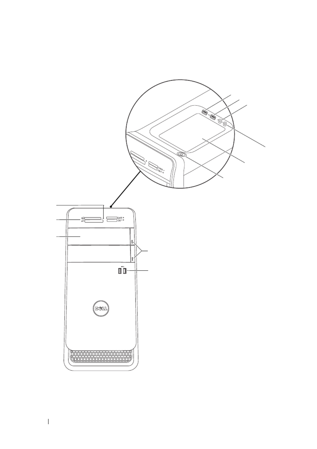
Front View of Your Computer
1
2
3
11
10
9
8
7
6
1
5
4

Technical Overview 19
Back View of Your Computer
1 2
3 4
5 6
7 8
9 10
11
1 2
3 4
5 6
7 8
9 10
11
2
1
10
3
4
5
6
7
8
9
11

20 Technical Overview
Inside View of Your Computer
7
2
1
9
5
6
4
8
3
Technical Overview 21
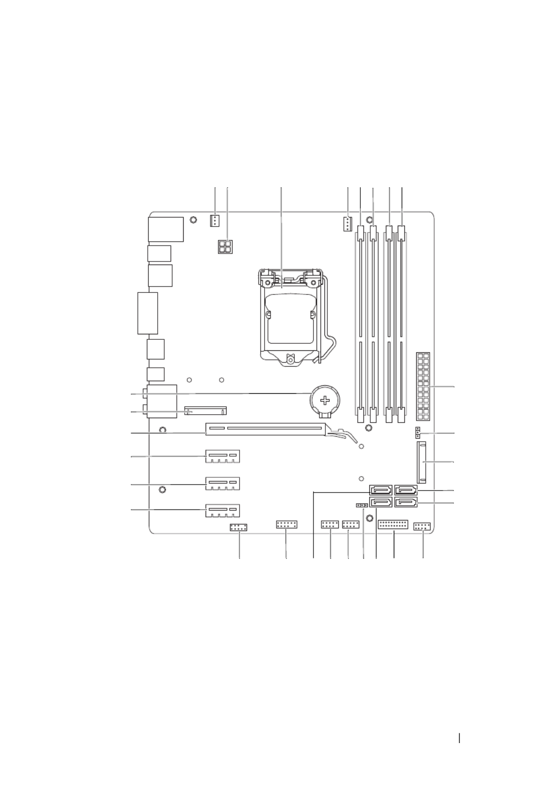
System-Board Components
1 2 3 4 5 6 7 8
9
10
11
12
13
141516171819202122
23
24
25
26
27
28

22 Technical Overview

Computer Cover 23
4
Computer Cover
WARNING: Before working inside your computer, read the safety information
that shipped with your computer and follow the steps in "Before You Begin" on
page 13. For additional safety best practices information, see the Regulatory
Compliance Homepage at dell.com/regulatory_compliance.
CAUTION: Ensure that sufficient space exists to support the computer with the
computer cover removed—at least 30 cm (1 ft.) of desk top space.
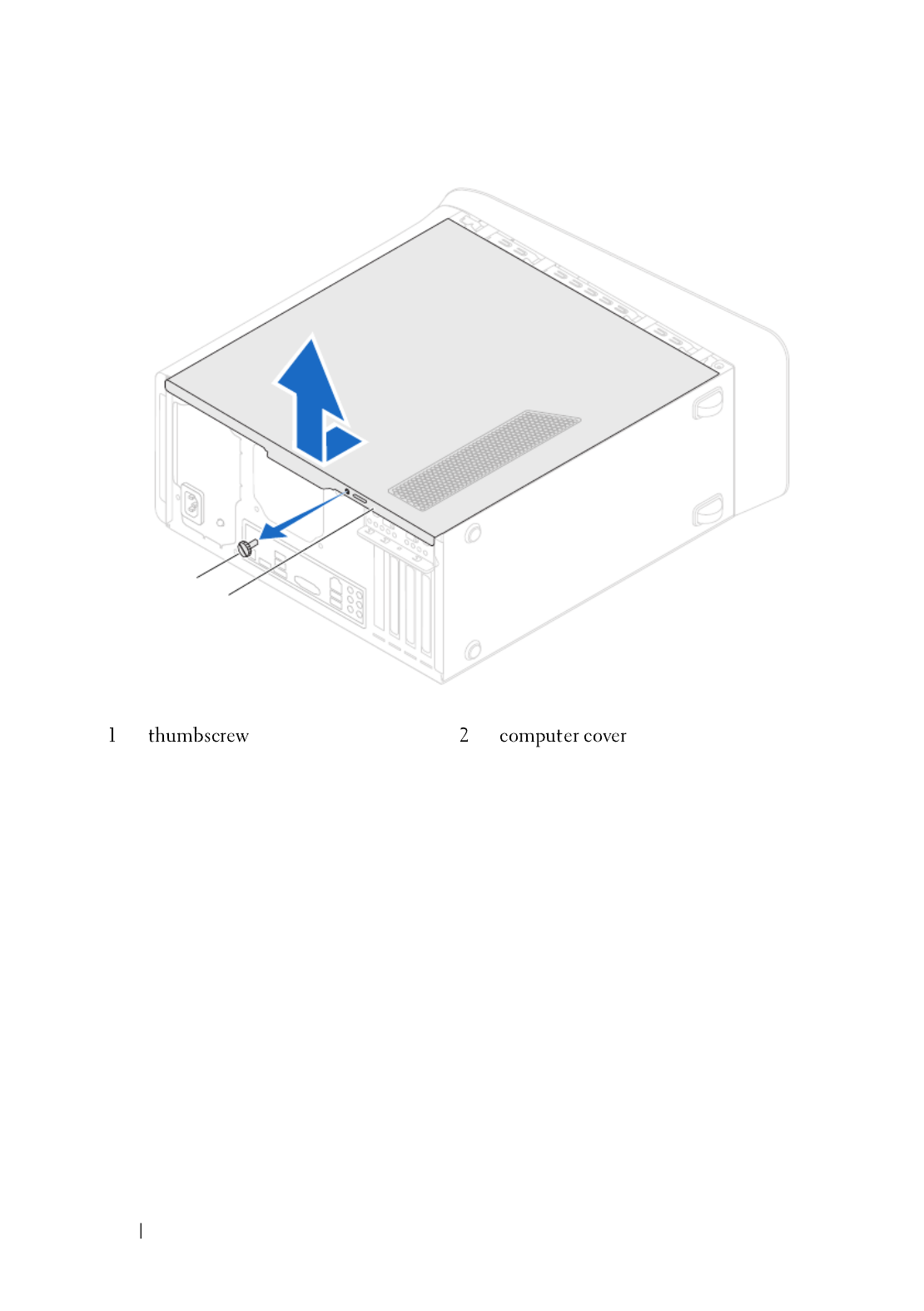
Removing the Computer Cover
NOTE: Ensure that you remove the security cable from the security cable slot (if
applicable).
1
Lay the computer on its side with the computer cover facing up.
2
Remove the thumbscrew that secures the computer cover to the chassis,
using a screw driver, if necessary.
3
Release the computer cover by sliding it away from the front of the
computer.
4
Lift the cover away from the computer and set it aside in a secure location.
24 Computer Cover
2
1

Computer Cover 25
Replacing the Computer Cover
1
2
3
4
5
6
7
12
3

26 Computer Cover

Memory Module(s) 27
5
Memory Module(s)
WARNING: Before working inside your computer, read the safety information
that shipped with your computer and follow the steps in "Before You Begin" on
page 13. For additional safety best practices information, see the Regulatory
Compliance Homepage at dell.com/regulatory_compliance.
Prerequisites
1
Removing Memory Module(s)
WARNING: The memory module(s) may become very hot during normal operation.
Allow the memory module(s) to cool before touching them.
1
2
1 securing clip 2 memory-module connector
1
2

28 Memory Module(s)
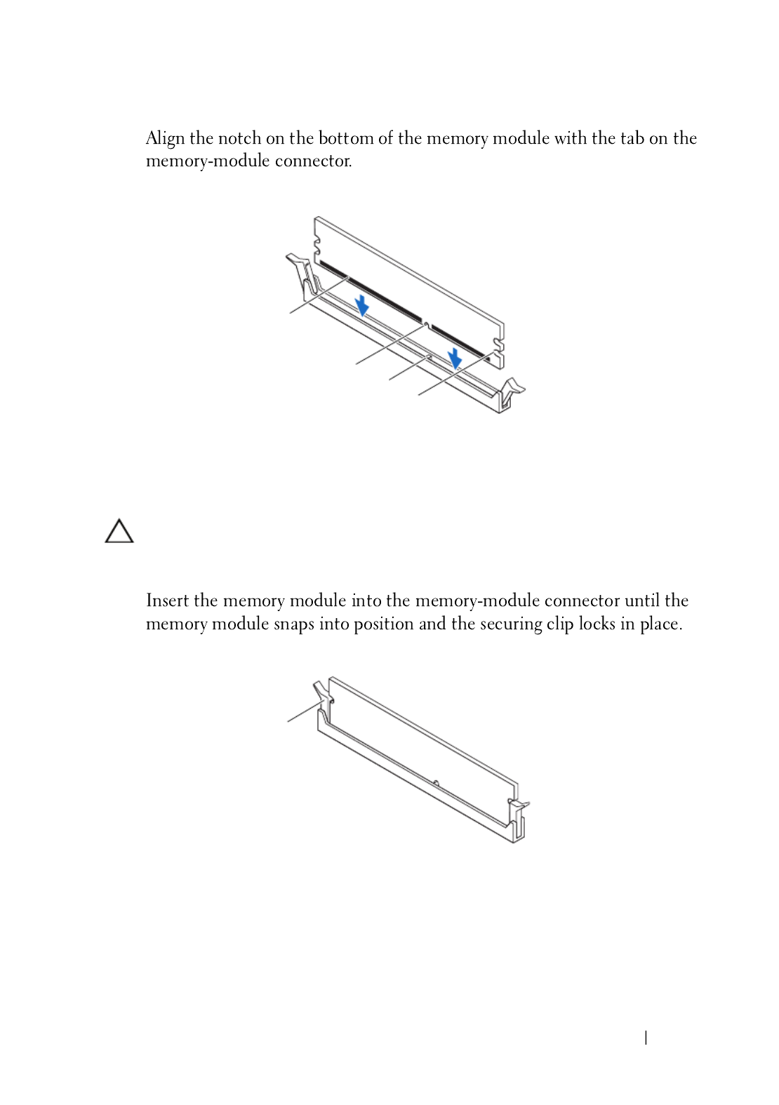
Replacing Memory Module(s)
CAUTION: If the memory module is not installed correctly, your computer may not
boot.
CAUTION: If you remove the original memory module(s) from your computer
during a memory upgrade, keep them separate from any new module(s) that you
may have, even if you purchased the new module(s) from Dell. If possible, do not
pair an original memory module with a new memory module. Otherwise, your
computer may not start properly. The recommended memory configurations are:
matched memory modules installed in DIMM connectors 1 and 2 and another
matched memory modules installed in DIMM connectors 3 and 4.
Type Slots
1600 MHz DDR3 Slots 1 and 2 or slots 1 through 4
Memory Module(s) 29
1
CAUTION: To avoid damage to the memory module, press the memory module
straight down into the connector while you apply equal force to each end of the
memory module.
2
1 memory module 2 notch
3 tab 4 cutouts (2)
1 securing clip (snapped in position)
1
2
4
3
1

30 Memory Module(s)
Postrequisites
1
2
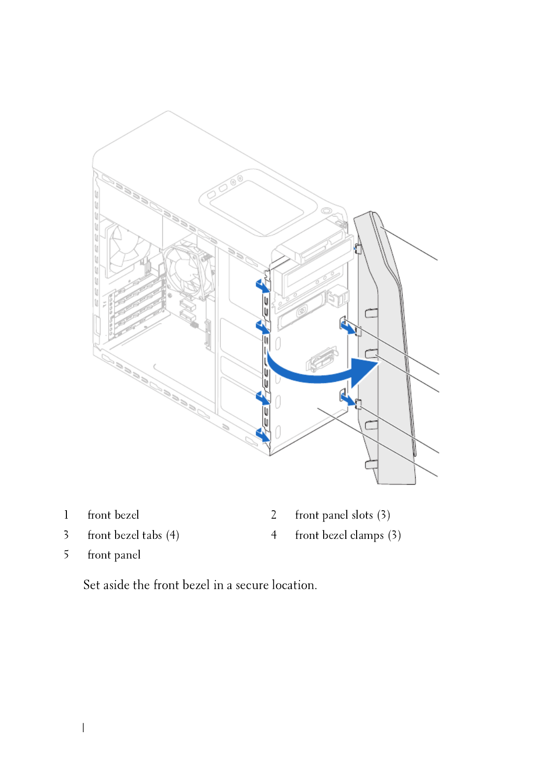
32 Front Bezel
4
3
4
2
1
5

Front Bezel 33
Replacing the Front Bezel
1
2
1 2
3 4
5
2
1
3
4
5

34 Front Bezel
Postrequisites
1
2
Produktspezifikationen
| Marke: | Dell |
| Kategorie: | Desktop |
| Modell: | XPS 8500 |
| Display-Typ: | LED |
| Touchscreen: | Nein |
| Bildschirmdiagonale: | 18.5 Zoll |
| Anzahl der Farben des Displays: | 16,78 Millionen Farben |
| Installiertes Betriebssystem: | Windows 7 Home Premium |
| Prozessorhersteller: | Intel |
| Anzahl Prozessorkerne: | 4 |
| WLAN: | Ja |
| WLAN-Standards: | 802.11b, 802.11g, Wi-Fi 4 (802.11n) |
| Breite: | 185 mm |
| Tiefe: | 445 mm |
| Gewicht: | 12860 g |
| Produkttyp: | PC |
| Produktfarbe: | Schwarz, Silber |
| Höhe: | 406 mm |
| Kopfhörerausgänge: | 1 |
| Anzahl USB 2.0 Anschlüsse: | 6 |
| Eingebauter Ethernet-Anschluss: | Ja |
| Anzahl Ethernet-LAN-Anschlüsse (RJ-45): | 1 |
| Natives Seitenverhältnis: | 16:9 |
| Helligkeit: | 250 cd/m² |
| Bildwinkel, horizontal: | 170 ° |
| Bildwinkel, vertikal: | 160 ° |
| Anzahl HDMI-Anschlüsse: | 1 |
| Ethernet LAN Datentransferraten: | 10,100,1000 Mbit/s |
| Stromversorgung: | 460 W |
| Mac-Kompatibilität: | Nein |
| DVI Anschluss: | Nein |
| Intel® Wireless-Display (Intel® WiDi): | Nein |
| Mikrofon-Eingang: | Ja |
| Netzteiltyp: | AC/DC |
| Prozessor-Taktfrequenz: | 3.4 GHz |
| Prozessorfamilie: | Intel® Core™ i7 |
| Prozessor: | i7-2600 |
| Plattform: | PC |
| RAM-Speicher: | 8 GB |
| USB 3.2 Gen 1 (3.1 Gen 1) Anzahl der Anschlüsse vom Typ A: | 4 |
| Gehäusetyp: | Mini Tower |
| Prozessor-Cache: | 8 MB |
| Prozessor Boost-Frequenz: | 3.8 GHz |
| Konfliktloser-Prozessor: | Nein |
| Frontsidebus des Prozessors: | - MHz |
| Prozessor Cache Typ: | Smart Cache |
| Prozessor-Code: | SR00B |
| Prozessor Codename: | Sandy Bridge |
| Prozessor Lithografie: | 32 nm |
| Prozessorbetriebsmodi: | 64-Bit |
| Prozessor-Paketgröße: | 37.5 x 37.5 mm |
| Prozessor-Threads: | 8 |
| Stepping: | D2 |
| Systembus-Rate: | 5 GT/s |
| Thermal Design Power (TDP): | 95 W |
| Prozessor-Serien: | Intel Core i7-2600 Desktop Series |
| Prozessorsockel: | LGA 1155 (Socket H2) |
| ARK Prozessorerkennung: | 52213 |
| Interner Speichertyp: | DDR3-SDRAM |
| Integrierter Kartenleser: | Ja |
| Top WLAN-Standard: | Wi-Fi 4 (802.11n) |
| Intel® Turbo-Boost-Technologie: | 2.0 |
| Eingebettete Optionen verfügbar: | Ja |
| Intel® 64: | Ja |
| Intel® Virtualization Technologie (VT-X): | Ja |
| Anzahl VGA (D-Sub) Anschlüsse: | 1 |
| Maximale Anzahl an SMP-Prozessoren: | 1 |
| Motherboard Chipsatz: | Intel® H77 Express |
| Speicherkanäle: | Zweikanalig |
| RAM-Speicher maximal: | 8 GB |
| Verkabelungstechnologie: | 10/100/1000Base-T(X) |
| HDD Kapazität: | 2000 GB |
| Gesamtspeicherkapazität: | 2000 GB |
| Intel® Hyper-Threading-Technik (Intel® HT Technology): | Ja |
| Intel® Identity-Protection-Technologie (Intel® IPT): | Ja |
| Verbesserte Intel SpeedStep Technologie: | Ja |
| Anzahl installierter Prozessoren: | 1 |
| PCI-Express-Slots-Version: | 2.0 |
| Maximale Anzahl der PCI-Express-Lanes: | 16 |
| Maximaler interner Speicher, vom Prozessor unterstützt: | 32 GB |
| Speichertypen, vom Prozessor unterstützt: | DDR3-SDRAM |
| Speichertaktraten, vom Prozessor unterstützt: | 1066,1333 MHz |
| Durch den Prozessor (max) unterstützte Speicherbandbreite: | 21 GB/s |
| Prozessorgeneration: | Intel® Core™ i7 der zweiten Generation |
| On-Board Grafikadaptermodell: | Intel® HD Graphics 2000 |
| Eingebaute Grafikadapter: | Ja |
| On-Board Grafikadapter Basisfrequenz: | 850 MHz |
| Maximale dynamische Frequenz der On-Board Grafikadapter: | 1350 MHz |
| On-Board Grafikadapter Geräte-ID: | 0x102 |
| Anzahl an unterstützen Displays (On-Board-Grafik): | 2 |
| On-Board-Grafikadapterfamilie: | Intel® HD Graphics |
| Speichertaktfrequenz: | 1600 MHz |
| Speicherkartensteckplätze: | 4x DIMM |
| Speicherlayout: | 2 x 4 GB |
| Anzahl der installierten HDDs: | 1 |
| Optisches Laufwerk - Typ: | Blu-Ray DVD Combo |
| Betriebssystemsarchitektur: | 64-Bit |
| Anzeige enthalten: | Ja |
| Unterstützte Befehlssätze: | AVX |
| Intel® Quick-Sync-Video-Technik: | Ja |
| Intel® InTru™ 3D Technologie: | Ja |
| Intel® Clear Video HD Technology für (Intel® CVT HD): | Ja |
| Intel® AES New Instructions (Intel® AES-NI): | Ja |
| Execute Disable Bit: | Ja |
| Leerlauf Zustände: | Ja |
| Thermal-Überwachungstechnologien: | Ja |
| Intel® Trusted-Execution-Technik: | Ja |
| CPU Konfiguration (max): | 1 |
| Intel® VT-x mit Extended Page Tables (EPT): | Ja |
| Intel® Virtualisierungstechnik für direkte I/O (VT-d): | Ja |
| Intel® Clear Video Technologie: | Nein |
| Grafikkarte-Familie: | Intel |
| Wake-on-LAN bereit: | Ja |
| Bus Typ: | DMI |
| ECC vom Prozessor unterstützt: | Nein |
| FSB Gleichwertigkeit: | Nein |
| HDD Schnittstelle: | SATA |
| Intel® My-WiFi-Technik (Intel® MWT): | Nein |
| Intel® Anti-Theft Technologie (Intel® AT): | Nein |
| Intel® Insider™: | Ja |
| Intel® Flex Memory Access: | Ja |
| Intel® Enhanced Halt State: | Ja |
| Intel® Demand Based Switching: | Nein |
| Intel® Clear Video Technology für Mobile Internet Devices (Intel® CVT for MID): | Nein |
| Intel® Identity Protection Technologieversion: | 1.00 |
| Intel® Dual Display Capable Technology: | Ja |
| Intel® FDI-Technik: | Ja |
| Intel® Rapid-Storage-Technik: | Nein |
| Intel® Fast Memory Access: | Ja |
| CPU-Multiplikator (Bus-/Kernverhältnis): | 34 |
| Bildertypenkarte: | <div><img src="https://ark.intel.com/inc/images/diagrams/diagram-18.gif" title="Block Diagram" /></div> |
| Konformität mit Industriestandards: | IEEE 802.3, IEEE 802.3u, IEEE 802.3ab |
| Tcase: | 72.6 °C |
| installierter Diskettenlaufwerk: | Nein |
| Display-Auflösung: | 1366 x 768 Pixel |
Brauchst du Hilfe?
Wenn Sie Hilfe mit Dell XPS 8500 benötigen, stellen Sie unten eine Frage und andere Benutzer werden Ihnen antworten
Bedienungsanleitung Desktop Dell

21 September 2024
17 September 2024
15 September 2024
5 September 2024
3 September 2024
31 August 2024
28 August 2024
28 August 2024
28 August 2024
28 August 2024
Bedienungsanleitung Desktop
- Desktop Samsung
- Desktop Acer
- Desktop Apple
- Desktop Asus
- Desktop BenQ
- Desktop Gigabyte
- Desktop HP
- Desktop Medion
- Desktop Microsoft
- Desktop Sharkoon
- Desktop Sony
- Desktop LG
- Desktop Sharp
- Desktop WOOOD
- Desktop Haier
- Desktop TrekStor
- Desktop Optoma
- Desktop PEAQ
- Desktop Toshiba
- Desktop Mio
- Desktop ViewSonic
- Desktop LC-Power
- Desktop Lenovo
- Desktop MSI
- Desktop JYSK
- Desktop Tripp Lite
- Desktop Razer
- Desktop ELO
- Desktop Targa
- Desktop Xoro
- Desktop Vtech
- Desktop Parisot
- Desktop Wehkamp
- Desktop Supermicro
- Desktop Faytech
- Desktop InFocus
- Desktop NEC
- Desktop Seagate
- Desktop Fujitsu
- Desktop Maxdata
- Desktop Packard Bell
- Desktop Kogan
- Desktop ZTE
- Desktop Atari
- Desktop Kramer
- Desktop Asrock
- Desktop ECS
- Desktop Promethean
- Desktop Vorago
- Desktop Emachines
- Desktop Ibm
- Desktop MP
- Desktop ONYX
- Desktop Alienware
- Desktop Zotac
- Desktop Intel
- Desktop Moxa
- Desktop VXL
- Desktop Planar
- Desktop Shuttle
- Desktop Altra
- Desktop Axis
- Desktop Advantech
- Desktop Elitegroup
- Desktop BDI
- Desktop Bestar
- Desktop Pelco
- Desktop Foxconn
- Desktop System76
- Desktop NComputing
- Desktop Cybernet
- Desktop Aopen
- Desktop Smart Things
- Desktop Zoostorm
- Desktop Dell Wyse
- Desktop MvixUSA
- Desktop AIS
- Desktop Wyse
Neueste Bedienungsanleitung für -Kategorien-

30 November 2024

15 Oktober 2024

14 Oktober 2024
12 Oktober 2024
11 Oktober 2024

9 Oktober 2024

9 Oktober 2024

7 Oktober 2024
4 Oktober 2024
4 Oktober 2024