Dell Precision R7610 Bedienungsanleitung
Lesen Sie kostenlos die 📖 deutsche Bedienungsanleitung für Dell Precision R7610 (123 Seiten) in der Kategorie Desktop. Dieser Bedienungsanleitung war für 6 Personen hilfreich und wurde von 2 Benutzern mit durchschnittlich 4.5 Sternen bewertet
Seite 1/123

Dell Precision Workstation R7610
Dell Precision Workstation R7610
Dell Precision Workstation R7610
Dell Precision Workstation R7610Dell Precision Workstation R7610
Owner's Manual
Owner's Manual
Owner's Manual
Owner's ManualOwner's Manual
Regulatory Model: E15S
Regulatory Model: E15S
Regulatory Model: E15S
Regulatory Model: E15SRegulatory Model: E15S
Regulatory Type: E15S002
Regulatory Type: E15S002
Regulatory Type: E15S002
Regulatory Type: E15S002Regulatory Type: E15S002

Notes, Cautions, and Warnings
Notes, Cautions, and Warnings
Notes, Cautions, and Warnings
Notes, Cautions, and WarningsNotes, Cautions, and Warnings
NOTE:
NOTE:
NOTE:
NOTE: NOTE: A NOTE indicates important information that helps you make better use of your computer.
CAUTION: A CAUTION indicates either potential damage to hardware or loss of data and tells you how to avoid the
CAUTION: A CAUTION indicates either potential damage to hardware or loss of data and tells you how to avoid the
CAUTION: A CAUTION indicates either potential damage to hardware or loss of data and tells you how to avoid the
CAUTION: A CAUTION indicates either potential damage to hardware or loss of data and tells you how to avoid the CAUTION: A CAUTION indicates either potential damage to hardware or loss of data and tells you how to avoid the
problem.
problem.
problem.
problem.problem.
WARNING: A WARNING indicates a potential for property damage, personal injury, or death.
WARNING: A WARNING indicates a potential for property damage, personal injury, or death.
WARNING: A WARNING indicates a potential for property damage, personal injury, or death.
WARNING: A WARNING indicates a potential for property damage, personal injury, or death.WARNING: A WARNING indicates a potential for property damage, personal injury, or death.
© 2013 Dell Inc.
2013 Dell Inc.
2013 Dell Inc.
2013 Dell Inc. 2013 Dell Inc.
Trademarks used in this text: Dell
™, the DELL logo, Dell Precision
™, Precision ON™,ExpressCharge™, Latitude™, Latitude ON
™,
OptiPlex™, Vostro™, and Wi-Fi Catcher™ are trademarks of Dell Inc. Intel®, Pentium®, Xeon®, Core™, Atom™, Centrino®, and Celeron®
are registered trademarks or trademarks of Intel Corporation in the U.S. and other countries. AMD
® is a registered trademark and
AMD Opteron™, AMD Phenom™, AMD Sempron™, AMD Athlon™, ATI Radeon™, and ATI FirePro™ are trademarks of Advanced Micro
Devices, Inc. Microsoft®, Windows®, MS-DOS®, Windows Vista®
, the Windows Vista start button, and Office Outlook
® are either
trademarks or registered trademarks of Microsoft Corporation in the United States and/or other countries. Blu-ray Disc
™ is a trademark
owned by the Blu-ray Disc Association (BDA) and licensed for use on discs and players. The Bluetooth
® word mark is a registered
trademark and owned by the Bluetooth® SIG, Inc. and any use of such mark by Dell Inc. is under license. Wi-Fi® is a registered
trademark of Wireless Ethernet Compatibility Alliance, Inc.
2013 - 05
Rev. A00

Contents
Contents
Contents
ContentsContents
Notes, Cautions, and Warnings
Notes, Cautions, and Warnings
Notes, Cautions, and Warnings
Notes, Cautions, and WarningsNotes, Cautions, and Warnings...................................................................................................2
...................................................................................................2
...................................................................................................2
...................................................................................................2...................................................................................................2
1 Working on Your Computer
1 Working on Your Computer
1 Working on Your Computer
1 Working on Your Computer1 Working on Your Computer.......................................................................................................7
.......................................................................................................7
.......................................................................................................7
.......................................................................................................7.......................................................................................................7
Before Working Inside Your Computer.....................................................................................................................7
Recommended Tools................................................................................................................................................8
Turning Off Your Computer.......................................................................................................................................8
After Working Inside Your Computer........................................................................................................................8
2 System Overview.......................................................................................................................
2 System Overview.......................................................................................................................
2 System Overview.......................................................................................................................
2 System Overview.......................................................................................................................2 System Overview.......................................................................................................................11
11
11
1111
3 Removing the Front Bezel
3 Removing the Front Bezel
3 Removing the Front Bezel
3 Removing the Front Bezel3 Removing the Front Bezel 13
13
13
1313
........................................................................................................
........................................................................................................
........................................................................................................
................................................................................................................................................................................................................
4 Installing the Front Bezel
4 Installing the Front Bezel
4 Installing the Front Bezel
4 Installing the Front Bezel4 Installing the Front Bezel 15
15
15
1515
.........................................................................................................
.........................................................................................................
.........................................................................................................
..................................................................................................................................................................................................................
5 Removing the Cover
5 Removing the Cover
5 Removing the Cover
5 Removing the Cover5 Removing the Cover 17
17
17
1717
..................................................................................................................
..................................................................................................................
..................................................................................................................
....................................................................................................................................................................................................................................
6 Installing the Cover
6 Installing the Cover
6 Installing the Cover
6 Installing the Cover6 Installing the Cover 19
19
19
1919
...................................................................................................................
...................................................................................................................
...................................................................................................................
......................................................................................................................................................................................................................................
7 Removing the Power Supply
7 Removing the Power Supply
7 Removing the Power Supply
7 Removing the Power Supply7 Removing the Power Supply 21
21
21
2121
...................................................................................................
...................................................................................................
...................................................................................................
......................................................................................................................................................................................................
8 Installing the Power Supply Unit
8 Installing the Power Supply Unit
8 Installing the Power Supply Unit
8 Installing the Power Supply Unit8 Installing the Power Supply Unit 23
23
23
2323
............................................................................................
............................................................................................
............................................................................................
........................................................................................................................................................................................
9 Removing the Hard Drive Carrier............................................................................................25
9 Removing the Hard Drive Carrier............................................................................................25
9 Removing the Hard Drive Carrier............................................................................................25
9 Removing the Hard Drive Carrier............................................................................................259 Removing the Hard Drive Carrier............................................................................................25
10 Installing the Hard Drive Carrier
10 Installing the Hard Drive Carrier
10 Installing the Hard Drive Carrier
10 Installing the Hard Drive Carrier10 Installing the Hard Drive Carrier 27
27
27
2727
...........................................................................................
...........................................................................................
...........................................................................................
......................................................................................................................................................................................
11 Removing the Hard Drive Assembly.....................................................................................
11 Removing the Hard Drive Assembly.....................................................................................
11 Removing the Hard Drive Assembly.....................................................................................
11 Removing the Hard Drive Assembly.....................................................................................11 Removing the Hard Drive Assembly.....................................................................................29
29
29
2929
12 Installing the Hard Drive Assembly
12 Installing the Hard Drive Assembly
12 Installing the Hard Drive Assembly
12 Installing the Hard Drive Assembly12 Installing the Hard Drive Assembly 31
31
31
3131
......................................................................................
......................................................................................
......................................................................................
............................................................................................................................................................................
13 Removing the Control Panel
13 Removing the Control Panel
13 Removing the Control Panel
13 Removing the Control Panel13 Removing the Control Panel 33
33
33
3333
..................................................................................................
..................................................................................................
..................................................................................................
....................................................................................................................................................................................................
14 Installing the Control Panel
14 Installing the Control Panel
14 Installing the Control Panel
14 Installing the Control Panel14 Installing the Control Panel 35
35
35
3535
...................................................................................................
...................................................................................................
...................................................................................................
......................................................................................................................................................................................................
15 Removing the Optical Drive
15 Removing the Optical Drive
15 Removing the Optical Drive
15 Removing the Optical Drive15 Removing the Optical Drive 37
37
37
3737
...................................................................................................
...................................................................................................
...................................................................................................
......................................................................................................................................................................................................
16 Installing the Optical Drive
16 Installing the Optical Drive
16 Installing the Optical Drive
16 Installing the Optical Drive16 Installing the Optical Drive 39
39
39
3939
....................................................................................................
....................................................................................................
....................................................................................................
........................................................................................................................................................................................................
17 Removing the Cooling Shroud
17 Removing the Cooling Shroud
17 Removing the Cooling Shroud
17 Removing the Cooling Shroud17 Removing the Cooling Shroud 41
41
41
4141
...............................................................................................
...............................................................................................
...............................................................................................
..............................................................................................................................................................................................

18 Installing the Cooling Shroud
18 Installing the Cooling Shroud
18 Installing the Cooling Shroud
18 Installing the Cooling Shroud 18 Installing the Cooling Shroud 43
43
43
4343
...............................................................................................
...............................................................................................
...............................................................................................
..............................................................................................................................................................................................
19 Removing the SAS (Serial attached SCSI) Backplane......................................................45
19 Removing the SAS (Serial attached SCSI) Backplane......................................................45
19 Removing the SAS (Serial attached SCSI) Backplane......................................................45
19 Removing the SAS (Serial attached SCSI) Backplane......................................................4519 Removing the SAS (Serial attached SCSI) Backplane......................................................45
20 Installing the SAS (Serial Attached SCSI) backplane
20 Installing the SAS (Serial Attached SCSI) backplane
20 Installing the SAS (Serial Attached SCSI) backplane
20 Installing the SAS (Serial Attached SCSI) backplane20 Installing the SAS (Serial Attached SCSI) backplane 47
47
47
4747
.......................................................
.......................................................
.......................................................
..............................................................................................................
21 Removing the Front-Chassis Assembly
21 Removing the Front-Chassis Assembly
21 Removing the Front-Chassis Assembly
21 Removing the Front-Chassis Assembly21 Removing the Front-Chassis Assembly 49
49
49
4949
...............................................................................
...............................................................................
...............................................................................
..............................................................................................................................................................
22 Installing the Front-Chassis Assembly
22 Installing the Front-Chassis Assembly
22 Installing the Front-Chassis Assembly
22 Installing the Front-Chassis Assembly22 Installing the Front-Chassis Assembly 51
51
51
5151
................................................................................
................................................................................
................................................................................
................................................................................................................................................................
23 Removing the Fan Bracket.....................................................................................................
23 Removing the Fan Bracket.....................................................................................................
23 Removing the Fan Bracket.....................................................................................................
23 Removing the Fan Bracket.....................................................................................................23 Removing the Fan Bracket.....................................................................................................53
53
53
5353
24 Installing the Fan Bracket
24 Installing the Fan Bracket
24 Installing the Fan Bracket
24 Installing the Fan Bracket24 Installing the Fan Bracket 55
55
55
5555
......................................................................................................
......................................................................................................
......................................................................................................
............................................................................................................................................................................................................
25 Removing the System Fans....................................................................................................
25 Removing the System Fans....................................................................................................
25 Removing the System Fans....................................................................................................
25 Removing the System Fans....................................................................................................25 Removing the System Fans....................................................................................................57
57
57
5757
26 Installing the System Fans
26 Installing the System Fans
26 Installing the System Fans
26 Installing the System Fans26 Installing the System Fans 59
59
59
5959
.....................................................................................................
.....................................................................................................
.....................................................................................................
..........................................................................................................................................................................................................
27 Removing the Coin-Cell Battery
27 Removing the Coin-Cell Battery
27 Removing the Coin-Cell Battery
27 Removing the Coin-Cell Battery27 Removing the Coin-Cell Battery 61
61
61
6161
............................................................................................
............................................................................................
............................................................................................
........................................................................................................................................................................................
28 Installing the Coin-Cell Battery
28 Installing the Coin-Cell Battery
28 Installing the Coin-Cell Battery
28 Installing the Coin-Cell Battery28 Installing the Coin-Cell Battery 63
63
63
6363
.............................................................................................
.............................................................................................
.............................................................................................
..........................................................................................................................................................................................
29 Removing the Memory
29 Removing the Memory
29 Removing the Memory
29 Removing the Memory29 Removing the Memory 65
65
65
6565
...........................................................................................................
...........................................................................................................
...........................................................................................................
......................................................................................................................................................................................................................
30 Installing the Memory.............................................................................................................
30 Installing the Memory.............................................................................................................
30 Installing the Memory.............................................................................................................
30 Installing the Memory.............................................................................................................30 Installing the Memory.............................................................................................................67
67
67
6767
31 Removing the Heat Sink
31 Removing the Heat Sink
31 Removing the Heat Sink
31 Removing the Heat Sink31 Removing the Heat Sink 69
69
69
6969
.........................................................................................................
.........................................................................................................
.........................................................................................................
..................................................................................................................................................................................................................
32 Installing the Heat Sink
32 Installing the Heat Sink
32 Installing the Heat Sink
32 Installing the Heat Sink32 Installing the Heat Sink 71
71
71
7171
..........................................................................................................
..........................................................................................................
..........................................................................................................
....................................................................................................................................................................................................................
33 Removing the Processor
33 Removing the Processor
33 Removing the Processor
33 Removing the Processor33 Removing the Processor 73
73
73
7373
........................................................................................................
........................................................................................................
........................................................................................................
................................................................................................................................................................................................................
34 Installing the Processor
34 Installing the Processor
34 Installing the Processor
34 Installing the Processor34 Installing the Processor 75
75
75
7575
.........................................................................................................
.........................................................................................................
.........................................................................................................
..................................................................................................................................................................................................................
35 Removing the Expansion Card Cages
35 Removing the Expansion Card Cages
35 Removing the Expansion Card Cages
35 Removing the Expansion Card Cages35 Removing the Expansion Card Cages 77
77
77
7777
..................................................................................
..................................................................................
..................................................................................
....................................................................................................................................................................
36 Installing the Expansion Card Cages
36 Installing the Expansion Card Cages
36 Installing the Expansion Card Cages
36 Installing the Expansion Card Cages36 Installing the Expansion Card Cages 81
81
81
8181
...................................................................................
...................................................................................
...................................................................................
......................................................................................................................................................................
37 Removing the Power-Distribution Unit
37 Removing the Power-Distribution Unit
37 Removing the Power-Distribution Unit
37 Removing the Power-Distribution Unit37 Removing the Power-Distribution Unit 83
83
83
8383
................................................................................
................................................................................
................................................................................
................................................................................................................................................................
38 Installing the Power-Distribution Unit
38 Installing the Power-Distribution Unit
38 Installing the Power-Distribution Unit
38 Installing the Power-Distribution Unit38 Installing the Power-Distribution Unit 85
85
85
8585
.................................................................................
.................................................................................
.................................................................................
..................................................................................................................................................................
39 Removing the Remote Access Host Card
39 Removing the Remote Access Host Card
39 Removing the Remote Access Host Card
39 Removing the Remote Access Host Card39 Removing the Remote Access Host Card 87
87
87
8787
...........................................................................
...........................................................................
...........................................................................
......................................................................................................................................................

40 Installing the Remote Access Host Card.............................................................................89
40 Installing the Remote Access Host Card.............................................................................89
40 Installing the Remote Access Host Card.............................................................................89
40 Installing the Remote Access Host Card.............................................................................8940 Installing the Remote Access Host Card.............................................................................89
41 Removing the SAS Controller Card
41 Removing the SAS Controller Card
41 Removing the SAS Controller Card
41 Removing the SAS Controller Card41 Removing the SAS Controller Card 91
91
91
9191
......................................................................................
......................................................................................
......................................................................................
............................................................................................................................................................................
42 Installing the SAS Controller Card........................................................................................93
42 Installing the SAS Controller Card........................................................................................93
42 Installing the SAS Controller Card........................................................................................93
42 Installing the SAS Controller Card........................................................................................9342 Installing the SAS Controller Card........................................................................................93
43 Removing the System Board
43 Removing the System Board
43 Removing the System Board
43 Removing the System Board43 Removing the System Board 95
95
95
9595
.................................................................................................
.................................................................................................
.................................................................................................
..................................................................................................................................................................................................
44 Installing the System Board
44 Installing the System Board
44 Installing the System Board
44 Installing the System Board44 Installing the System Board 97
97
97
9797
..................................................................................................
..................................................................................................
..................................................................................................
....................................................................................................................................................................................................
45 System Board Components
45 System Board Components
45 System Board Components
45 System Board Components45 System Board Components 99
99
99
9999
...................................................................................................
...................................................................................................
...................................................................................................
......................................................................................................................................................................................................
46 Troubleshooting.....................................................................................................................
46 Troubleshooting.....................................................................................................................
46 Troubleshooting.....................................................................................................................
46 Troubleshooting.....................................................................................................................46 Troubleshooting.....................................................................................................................101
101
101
101101
Diagnostic LEDs....................................................................................................................................................101
Error Messages....................................................................................................................................................107
Errors That Halt the System Completely........................................................................................................107
Errors That Soft Halt the System....................................................................................................................107
Errors That Do Not Halt the System...............................................................................................................108
47 Specifications
47 Specifications
47 Specifications
47 Specifications47 Specifications 109
109
109
109109
........................................................................................................................
........................................................................................................................
........................................................................................................................
................................................................................................................................................................................................................................................
48 System Setup
48 System Setup
48 System Setup
48 System Setup48 System Setup 115
115
115
115115
.........................................................................................................................
.........................................................................................................................
.........................................................................................................................
..................................................................................................................................................................................................................................................
Boot Menu............................................................................................................................................................115
Timing Key Sequences.........................................................................................................................................115
Dell Diagnostics....................................................................................................................................................116
System Setup Options...........................................................................................................................................116
49 Contacting Dell
49 Contacting Dell
49 Contacting Dell
49 Contacting Dell49 Contacting Dell 123
123
123
123123
......................................................................................................................
......................................................................................................................
......................................................................................................................
............................................................................................................................................................................................................................................
Contacting Dell.....................................................................................................................................................123

6

1
1
1
11
Working on Your Computer
Working on Your Computer
Working on Your Computer
Working on Your ComputerWorking on Your Computer
Before Working Inside Your Computer
Before Working Inside Your Computer
Before Working Inside Your Computer
Before Working Inside Your ComputerBefore Working Inside Your Computer
Use the following safety guidelines to help protect your computer from potential damage and to help to ensure your
personal safety. Unless otherwise noted, each procedure included in this document assumes that the following
conditions exist:
• You have read the safety information that shipped with your computer.
• A component can be replaced or--if purchased separately--installed by performing the removal procedure in
reverse order.
WARNING: Before working inside your computer, read the safety information that shipped with your computer. For
WARNING: Before working inside your computer, read the safety information that shipped with your computer. For
WARNING: Before working inside your computer, read the safety information that shipped with your computer. For
WARNING: Before working inside your computer, read the safety information that shipped with your computer. For WARNING: Before working inside your computer, read the safety information that shipped with your computer. For
additional safety best practices information, see the Regulatory Compliance Homepage at www.dell.com/
additional safety best practices information, see the Regulatory Compliance Homepage at www.dell.com/
additional safety best practices information, see the Regulatory Compliance Homepage at www.dell.com/
additional safety best practices information, see the Regulatory Compliance Homepage at www.dell.com/additional safety best practices information, see the Regulatory Compliance Homepage at www.dell.com/
regulatory_compliance
regulatory_compliance
regulatory_compliance
regulatory_compliance regulatory_compliance
CAUTION: Many repairs may only be done by a certified service technician. You should only perform
CAUTION: Many repairs may only be done by a certified service technician. You should only perform
CAUTION: Many repairs may only be done by a certified service technician. You should only perform
CAUTION: Many repairs may only be done by a certified service technician. You should only perform CAUTION: Many repairs may only be done by a certified service technician. You should only perform
troubleshooting and simple repairs as authorized in your product documentation, or as directed by the online or
troubleshooting and simple repairs as authorized in your product documentation, or as directed by the online or
troubleshooting and simple repairs as authorized in your product documentation, or as directed by the online or
troubleshooting and simple repairs as authorized in your product documentation, or as directed by the online or troubleshooting and simple repairs as authorized in your product documentation, or as directed by the online or
telephone service and support team. Damage due to servicing that is not authorized by Dell is not covered by your
telephone service and support team. Damage due to servicing that is not authorized by Dell is not covered by your
telephone service and support team. Damage due to servicing that is not authorized by Dell is not covered by your
telephone service and support team. Damage due to servicing that is not authorized by Dell is not covered by your telephone service and support team. Damage due to servicing that is not authorized by Dell is not covered by your
warranty. Read and follow the safety instructions that came with the product.
warranty. Read and follow the safety instructions that came with the product.
warranty. Read and follow the safety instructions that came with the product.
warranty. Read and follow the safety instructions that came with the product.warranty. Read and follow the safety instructions that came with the product.
CAUTION: To avoid electrostatic discharge, ground yourself by using a wrist grounding strap or by periodically
CAUTION: To avoid electrostatic discharge, ground yourself by using a wrist grounding strap or by periodically
CAUTION: To avoid electrostatic discharge, ground yourself by using a wrist grounding strap or by periodically
CAUTION: To avoid electrostatic discharge, ground yourself by using a wrist grounding strap or by periodically CAUTION: To avoid electrostatic discharge, ground yourself by using a wrist grounding strap or by periodically
touching an unpainted metal surface, such as a connector on the back of the computer.
touching an unpainted metal surface, such as a connector on the back of the computer.
touching an unpainted metal surface, such as a connector on the back of the computer.
touching an unpainted metal surface, such as a connector on the back of the computer.touching an unpainted metal surface, such as a connector on the back of the computer.
CAUTION: Handle components and cards with care. Do not touch the components or contacts on a card. Hold a
CAUTION: Handle components and cards with care. Do not touch the components or contacts on a card. Hold a
CAUTION: Handle components and cards with care. Do not touch the components or contacts on a card. Hold a
CAUTION: Handle components and cards with care. Do not touch the components or contacts on a card. Hold a CAUTION: Handle components and cards with care. Do not touch the components or contacts on a card. Hold a
card by its edges or by its metal mounting bracket. Hold a component such as a processor by its edges, not by its
card by its edges or by its metal mounting bracket. Hold a component such as a processor by its edges, not by its
card by its edges or by its metal mounting bracket. Hold a component such as a processor by its edges, not by its
card by its edges or by its metal mounting bracket. Hold a component such as a processor by its edges, not by its card by its edges or by its metal mounting bracket. Hold a component such as a processor by its edges, not by its
pins.
pins.
pins.
pins.pins.
CAUTION: When you disconnect a cable, pull on its connector or on its pull-tab, not on the cable itself. Some
CAUTION: When you disconnect a cable, pull on its connector or on its pull-tab, not on the cable itself. Some
CAUTION: When you disconnect a cable, pull on its connector or on its pull-tab, not on the cable itself. Some
CAUTION: When you disconnect a cable, pull on its connector or on its pull-tab, not on the cable itself. Some CAUTION: When you disconnect a cable, pull on its connector or on its pull-tab, not on the cable itself. Some
cables have connectors with locking tabs; if you are disconnecting this type of cable, press in on the locking tabs
cables have connectors with locking tabs; if you are disconnecting this type of cable, press in on the locking tabs
cables have connectors with locking tabs; if you are disconnecting this type of cable, press in on the locking tabs
cables have connectors with locking tabs; if you are disconnecting this type of cable, press in on the locking tabs cables have connectors with locking tabs; if you are disconnecting this type of cable, press in on the locking tabs
before you disconnect the cable. As you pull connectors apart, keep them evenly aligned to avoid bending any
before you disconnect the cable. As you pull connectors apart, keep them evenly aligned to avoid bending any
before you disconnect the cable. As you pull connectors apart, keep them evenly aligned to avoid bending any
before you disconnect the cable. As you pull connectors apart, keep them evenly aligned to avoid bending any before you disconnect the cable. As you pull connectors apart, keep them evenly aligned to avoid bending any
connector pins. Also, before you connect a cable, ensure that both connectors are correctly oriented and aligned.
connector pins. Also, before you connect a cable, ensure that both connectors are correctly oriented and aligned.
connector pins. Also, before you connect a cable, ensure that both connectors are correctly oriented and aligned.
connector pins. Also, before you connect a cable, ensure that both connectors are correctly oriented and aligned.connector pins. Also, before you connect a cable, ensure that both connectors are correctly oriented and aligned.
NOTE:
NOTE:
NOTE:
NOTE: NOTE: The color of your computer and certain components may appear differently than shown in this document.
To avoid damaging your computer, perform the following steps before you begin working inside the computer.
1.
1.
1.
1.1. Ensure that your work surface is flat and clean to prevent the computer cover from being scratched.
2.
2.
2.
2.2. Turn off your computer (see Turning Off Your Computer).
CAUTION: To disconnect a network cable, first unplug the cable from your computer and then unplug the
CAUTION: To disconnect a network cable, first unplug the cable from your computer and then unplug the
CAUTION: To disconnect a network cable, first unplug the cable from your computer and then unplug the
CAUTION: To disconnect a network cable, first unplug the cable from your computer and then unplug the CAUTION: To disconnect a network cable, first unplug the cable from your computer and then unplug the
cable from the network device.
cable from the network device.
cable from the network device.
cable from the network device.cable from the network device.
3.
3.
3.
3.3. Disconnect all network cables from the computer.
4.
4.
4.
4.4. Disconnect your computer and all attached devices from their electrical outlets.
5.
5.
5.
5.5. Press and hold the power button while the computer is unplugged to ground the system board.
6.
6.
6.
6.6. Remove the cover.
7

CAUTION: Before touching anything inside your computer, ground yourself by touching an unpainted metal
CAUTION: Before touching anything inside your computer, ground yourself by touching an unpainted metal
CAUTION: Before touching anything inside your computer, ground yourself by touching an unpainted metal
CAUTION: Before touching anything inside your computer, ground yourself by touching an unpainted metal CAUTION: Before touching anything inside your computer, ground yourself by touching an unpainted metal
surface, such as the metal at the back of the computer. While you work, periodically touch an unpainted metal
surface, such as the metal at the back of the computer. While you work, periodically touch an unpainted metal
surface, such as the metal at the back of the computer. While you work, periodically touch an unpainted metal
surface, such as the metal at the back of the computer. While you work, periodically touch an unpainted metal surface, such as the metal at the back of the computer. While you work, periodically touch an unpainted metal
surface to dissipate static electricity, which could harm internal components.
surface to dissipate static electricity, which could harm internal components.
surface to dissipate static electricity, which could harm internal components.
surface to dissipate static electricity, which could harm internal components.surface to dissipate static electricity, which could harm internal components.
Recommended Tools
Recommended Tools
Recommended Tools
Recommended ToolsRecommended Tools
The procedures in this document may require the following tools:
• Small flat-blade screwdriver
• Phillips screwdriver
• Small plastic scribe
Turning Off Your Computer
Turning Off Your Computer
Turning Off Your Computer
Turning Off Your ComputerTurning Off Your Computer
CAUTION: To avoid losing data, save and close all open files and exit all open programs before you turn off your
CAUTION: To avoid losing data, save and close all open files and exit all open programs before you turn off your
CAUTION: To avoid losing data, save and close all open files and exit all open programs before you turn off your
CAUTION: To avoid losing data, save and close all open files and exit all open programs before you turn off your CAUTION: To avoid losing data, save and close all open files and exit all open programs before you turn off your
computer.
computer.
computer.
computer.computer.
1.
1.
1.
1.1. Shut down the operating system:
– In Windows 8:
* Using a touch-enabled device:
a. Swipe in from the right edge of the screen, opening the Charms menu and select .
Settings
Settings
Settings
SettingsSettings
b. Select the and then select Shut down
Shut down
Shut down
Shut downShut down
* Using a mouse:
a. Point to upper-right corner of the screen and click .
Settings
Settings
Settings
SettingsSettings
b. Click the and select .
Shut down
Shut down
Shut down
Shut downShut down
– In Windows 7:
1. Click .
Start
Start
Start
StartStart
2. Click Shut Down.
Shut Down.
Shut Down.
Shut Down.Shut Down.
or
1. Click .
Start
Start
Start
StartStart
2. Click the arrow in the lower-right corner of the menu as shown below, and then click
Start
Start
Start
StartStart Shut
Shut
Shut
Shut Shut
Down.
Down.
Down.
Down.Down..
2.
2.
2.
2.2. Ensure that the computer and all attached devices are turned off. If your computer and attached devices did not
automatically turn off when you shut down your operating system, press and hold the power button for about 6
seconds to turn them off.
After Working Inside Your Computer
After Working Inside Your Computer
After Working Inside Your Computer
After Working Inside Your ComputerAfter Working Inside Your Computer
After you complete any replacement procedure, ensure you connect any external devices, cards, and cables before
turning on your computer.
1.
1.
1.
1.1. Replace the cover.
8

CAUTION: To connect a network cable, first plug the cable into the network device and then plug it into the
CAUTION: To connect a network cable, first plug the cable into the network device and then plug it into the
CAUTION: To connect a network cable, first plug the cable into the network device and then plug it into the
CAUTION: To connect a network cable, first plug the cable into the network device and then plug it into the CAUTION: To connect a network cable, first plug the cable into the network device and then plug it into the
computer.
computer.
computer.
computer.computer.
2.
2.
2.
2.2. Connect any telephone or network cables to your computer.
3.
3.
3.
3.3. Connect your computer and all attached devices to their electrical outlets.
4.
4.
4.
4.4. Turn on your computer.
5.
5.
5.
5.5. If required, verify that the computer works correctly by running the Dell Diagnostics.
9

10
2
2
2
22
System Overview
System Overview
System Overview
System OverviewSystem Overview
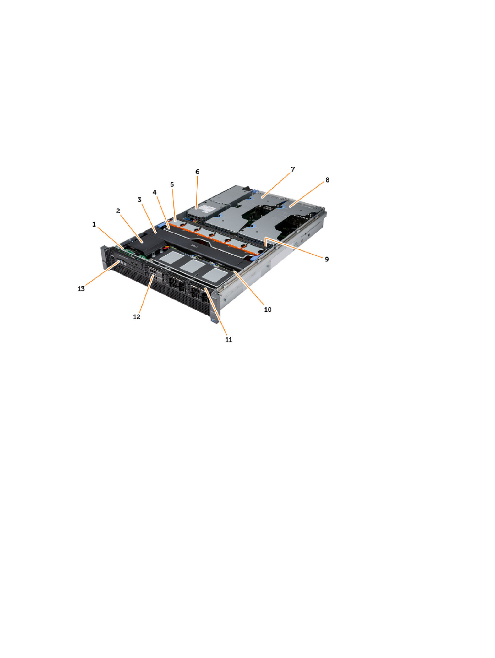
The figure below displays the inside view of the computer after the front bezel and the cover have been removed. The
callouts show the names and the layout of the components inside the computer.
1. control panel
2. plastic cover
3. cooling shroud
4. fan bracket
5. system fans
6. power distribution unit
7. center expansion-card cage
8. outer expansion-card cage
9. coin-cell battery
10. SAS back plane
11. front-chassis assembly
12. hard drive
13. optical drive
11

12

3
3
3
33
Removing the Front Bezel
Removing the Front Bezel
Removing the Front Bezel
Removing the Front BezelRemoving the Front Bezel
1.
1.
1.
1.1. Follow the procedures in
Before Working Inside Your Computer
.
2.
2.
2.
2.2. Unlock the front bezel using the key provided.
a) Lift the bezel-release tab and pull the front bezel away from the computer.
13

14

4
4
4
44
Installing the Front Bezel
Installing the Front Bezel
Installing the Front Bezel
Installing the Front BezelInstalling the Front Bezel
1.
1.
1.
1.1. Insert the front bezel in its slot in a downward direction and push it towards the computer.
2.
2.
2.
2.2. Secure the release tab.
3.
3.
3.
3.3. Lock the front bezel using the key provided.
4.
4.
4.
4.4. Follow the procedures in
After Working Inside Your Computer
.
15

16

5
5
5
55
Removing the Cover
Removing the Cover
Removing the Cover
Removing the CoverRemoving the Cover
1.
1.
1.
1.1. Follow the procedures in
Before Working Inside Your Computer
.
2.
2.
2.
2.2. Remove:
– front bezel
3.
3.
3.
3.3. Rotate the latch-release lock counter-clockwise to the unlocked position.
a) Lift the latch and slide the cover towards the back of the computer.
4.
4.
4.
4.4. Lift the cover away from the computer.
17

18

6
6
6
66
Installing the Cover
Installing the Cover
Installing the Cover
Installing the CoverInstalling the Cover
1.
1.
1.
1.1. Place the cover on the computer and press it down until it clicks into place.
2.
2.
2.
2.2. Press down the cover latch.
3.
3.
3.
3.3. Install the front bezel.
4.
4.
4.
4.4. Follow the procedures in
After Working Inside Your Computer
.
19

20

7
7
7
77
Removing the Power Supply
Removing the Power Supply
Removing the Power Supply
Removing the Power SupplyRemoving the Power Supply
1.
1.
1.
1.1. Follow the procedures in
Before Working Inside Your Computer
.
2.
2.
2.
2.2. Press and hold the orange tab towards the latch and pull the power supply unit away from the computer.
21

8
8
8
88
Installing the Power Supply Unit
Installing the Power Supply Unit
Installing the Power Supply Unit
Installing the Power Supply UnitInstalling the Power Supply Unit
1.
1.
1.
1.1. Insert the power supply unit into the computer until it clicks into place.
2.
2.
2.
2.2. Follow the procedures in
After Working Inside Your Computer
.
23

24

9
9
9
99
Removing the Hard Drive Carrier
Removing the Hard Drive Carrier
Removing the Hard Drive Carrier
Removing the Hard Drive CarrierRemoving the Hard Drive Carrier
1.
1.
1.
1.1. Follow the procedures in
Before Working Inside Your Computer
.
2.
2.
2.
2.2. Remove the front bezel.
3.
3.
3.
3.3. Press the hard-drive carrier release button.
a) Pull the hard-drive carrier handle open.
b) Slide the hard drive out of the drive bay.
25

10
10
10
1010
Installing the Hard Drive Carrier
Installing the Hard Drive Carrier
Installing the Hard Drive Carrier
Installing the Hard Drive CarrierInstalling the Hard Drive Carrier
1.
1.
1.
1.1. Insert the hard drive into the drive bay.
2.
2.
2.
2.2. Press the hard-drive carrier handle until it clicks into place.
3.
3.
3.
3.3. Install the front bezel.
4.
4.
4.
4.4. Follow the procedures in
After Working Inside Your Computer
.
27

28

11
11
11
1111
Removing the Hard Drive Assembly
Removing the Hard Drive Assembly
Removing the Hard Drive Assembly
Removing the Hard Drive AssemblyRemoving the Hard Drive Assembly
1.
1.
1.
1.1. Follow the procedures in
Before Working Inside Your Computer
.
2.
2.
2.
2.2. Remove:
– front bezel
– hard drive carrier
3.
3.
3.
3.3. Remove the screws that secure the hard drive caddy to the hard drive.
a) Slide the hard drive out of the drive assembly.
29

30

12
12
12
1212
Installing the Hard Drive Assembly
Installing the Hard Drive Assembly
Installing the Hard Drive Assembly
Installing the Hard Drive AssemblyInstalling the Hard Drive Assembly
1.
1.
1.
1.1. Place the hard drive in the hard-drive caddy.
2.
2.
2.
2.2. Tighten the screws that secure the hard drive on either side of the hard-drive caddy.
3.
3.
3.
3.3. Install :
– hard drive carrier
– front bezel
4.
4.
4.
4.4. Follow the procedures in
After Working Inside Your Computer
.
31

32

34

14
14
14
1414
Installing the Control Panel
Installing the Control Panel
Installing the Control Panel
Installing the Control PanelInstalling the Control Panel
1.
1.
1.
1.1. Connect the control panel cables.
2.
2.
2.
2.2. Install the screws that secure the control panel.
3.
3.
3.
3.3. Replace the torx screw that secures the control panel.
4.
4.
4.
4.4. Install :
– cover
– front bezel.
5.
5.
5.
5.5. Follow the procedures in
After Working Inside Your Computer
.
35

36

15
15
15
1515
Removing the Optical Drive
Removing the Optical Drive
Removing the Optical Drive
Removing the Optical DriveRemoving the Optical Drive
1.
1.
1.
1.1. Follow the procedures in
Before Working Inside Your Computer
.
2.
2.
2.
2.2. Remove:
– front bezel
– cover
– cooling shroud
3.
3.
3.
3.3. Push the blue release tab in the direction indicated and lift the plastic cover.
a) Release the plastic cover from the hinges that secure it on the other side and remove it from the computer.
4.
4.
4.
4.4. Disconnect the power and data cables from the optical drive.
a) Press down and push the blue release tab towards the front of the computer.
b) Slide the optical drive out through the front of the computer .
37

38

17
17
17
1717
Removing the Cooling Shroud
Removing the Cooling Shroud
Removing the Cooling Shroud
Removing the Cooling ShroudRemoving the Cooling Shroud
1.
1.
1.
1.1. Follow the procedures in
Before Working Inside Your Computer
.
2.
2.
2.
2.2. Remove:
– front bezel
– cover
3.
3.
3.
3.3. Lift the cooling shroud straight up and away from the system board.
41

42

18
18
18
1818
Installing the Cooling Shroud
Installing the Cooling Shroud
Installing the Cooling Shroud
Installing the Cooling Shroud Installing the Cooling Shroud
1.
1.
1.
1.1. Place the cooling shroud in front of the system fans into the system board.
2.
2.
2.
2.2. Install:
– cover
– front bezel
3.
3.
3.
3.3. Follow the procedures in
After Working Inside Your Computer
.
43

44

46

20
20
20
2020
Installing the SAS (Serial Attached SCSI)
Installing the SAS (Serial Attached SCSI)
Installing the SAS (Serial Attached SCSI)
Installing the SAS (Serial Attached SCSI) Installing the SAS (Serial Attached SCSI)
backplane
backplane
backplane
backplanebackplane
1.
1.
1.
1.1. Push the blue release tabs and insert the backplane in the slot on the system board along the hard-drive assembly.
2.
2.
2.
2.2. Connect the SAS cables.
3.
3.
3.
3.3. Install:
– hard-drive assembly
– hard-drive carrier
– optical drive
– cooling shroud
– cover
– front bezel
4.
4.
4.
4.4. Follow the procedures in
After Working Inside Your Computer
.
47

48

21
21
21
2121
Removing the Front-Chassis Assembly
Removing the Front-Chassis Assembly
Removing the Front-Chassis Assembly
Removing the Front-Chassis AssemblyRemoving the Front-Chassis Assembly
1.
1.
1.
1.1. Follow the procedures in
Before Working Inside Your Computer
.
2.
2.
2.
2.2. Remove:
– front bezel
– cover
– cooling shroud
3.
3.
3.
3.3. Press inwards on the two release tabs and slide the front-chassis assembly towards the front of the computer .
49

22
22
22
2222
Installing the Front-Chassis Assembly
Installing the Front-Chassis Assembly
Installing the Front-Chassis Assembly
Installing the Front-Chassis AssemblyInstalling the Front-Chassis Assembly
1.
1.
1.
1.1. Slide the front-chassis assembly towards the back of the computer until it clicks into place.
2.
2.
2.
2.2. Install:
– cooling shroud
– cover
– front bezel
3.
3.
3.
3.3. Follow the procedures in
After Working Inside Your Computer
.
51

23
23
23
2323
Removing the Fan Bracket
Removing the Fan Bracket
Removing the Fan Bracket
Removing the Fan BracketRemoving the Fan Bracket
1.
1.
1.
1.1. Follow the procedures in
Before Working Inside Your Computer
.
2.
2.
2.
2.2. Remove:
– cover
– cooling shroud
3.
3.
3.
3.3. Pull both release tabs upwards simultaneously to release the fan bracket.
a) Lift the fan-bracket and remove it from the computer.
53

54

24
24
24
2424
Installing the Fan Bracket
Installing the Fan Bracket
Installing the Fan Bracket
Installing the Fan BracketInstalling the Fan Bracket
1.
1.
1.
1.1. Place the fan bracket in the computer.
2.
2.
2.
2.2. Ensure that there are no cables on top of the fan connectors.
3.
3.
3.
3.3. Press both release tabs downwards simultaneously to secure the bracket.
4.
4.
4.
4.4. Install:
– cooling shroud
– cover
5.
5.
5.
5.5. Follow the procedures in
After Working Inside Your Computer
.
55

56

25
25
25
2525
Removing the System Fans
Removing the System Fans
Removing the System Fans
Removing the System FansRemoving the System Fans
1.
1.
1.
1.1. Follow the procedures in
Before Working Inside Your Computer
.
2.
2.
2.
2.2. Remove:
– cover
– front chassis assembly
3.
3.
3.
3.3. Press the release tab and lift the fan out of the system fan assembly.
a) Repeat the above step to remove the remaining system fans from the assembly.
57

58

26
26
26
2626
Installing the System Fans
Installing the System Fans
Installing the System Fans
Installing the System FansInstalling the System Fans
1.
1.
1.
1.1. Insert the fan in the system fan assembly until it clicks into place.
2.
2.
2.
2.2. Repeat the above step to install the remaining system fans into the assembly.
3.
3.
3.
3.3. Install:
– front chassis assembly
– cover
4.
4.
4.
4.4. Follow the procedures in
After Working Inside Your Computer
.
59

60

27
27
27
2727
Removing the Coin-Cell Battery
Removing the Coin-Cell Battery
Removing the Coin-Cell Battery
Removing the Coin-Cell BatteryRemoving the Coin-Cell Battery
1.
1.
1.
1.1. Follow the procedures in
Before Working Inside Your Computer
.
2.
2.
2.
2.2. Remove:
– front bezel
– cover
– cooling shroud
– fan bracket
3.
3.
3.
3.3. Press the release latch away from the battery to allow the battery to pop-up from the socket. Lift the coin-cell
battery out of the computer.
61

62

28
28
28
2828
Installing the Coin-Cell Battery
Installing the Coin-Cell Battery
Installing the Coin-Cell Battery
Installing the Coin-Cell BatteryInstalling the Coin-Cell Battery
1.
1.
1.
1.1. Place the coin-cell battery into the slot on the system board.
2.
2.
2.
2.2. Press the coin-cell battery downward until the release latch springs back into place and secures it.
3.
3.
3.
3.3. Install:
– fan bracket
– cooling shroud
– cover
– front bezel
4.
4.
4.
4.4. Follow the procedures in
After Working Inside Your Computer
.
63

64

29
29
29
2929
Removing the Memory
Removing the Memory
Removing the Memory
Removing the MemoryRemoving the Memory
1.
1.
1.
1.1. Follow the procedures in
Before Working Inside Your Computer
.
2.
2.
2.
2.2. Remove:
– front bezel
– cover
– cooling shroud
– front chassis assembly
– fan bracket
3.
3.
3.
3.3. Press down on the memory-securing clips on each side of the memory module, and lift the memory module
upwards to remove it from the computer.
65

30
30
30
3030
Installing the Memory
Installing the Memory
Installing the Memory
Installing the MemoryInstalling the Memory
1.
1.
1.
1.1. Insert the memory module into the memory socket.
2.
2.
2.
2.2. Press down on the memory module until the securing clips secure the memory in place.
3.
3.
3.
3.3. Install:
– fan bracket
– front chassis assembly
– cooling shroud
– cover
– front bezel
4.
4.
4.
4.4. Follow the procedures in
After Working Inside Your Computer
.
67

68

31
31
31
3131
Removing the Heat Sink
Removing the Heat Sink
Removing the Heat Sink
Removing the Heat SinkRemoving the Heat Sink
1.
1.
1.
1.1. Follow the procedures in
Before Working Inside Your Computer
.
2.
2.
2.
2.2. Remove:
– front bezel
– cover
– cooling shroud
– fan bracket
3.
3.
3.
3.3. Slide the front chassis assembly forward.
4.
4.
4.
4.4. Loosen the captive screws on the heat sink. It is recommended to begin loosening the diagonal-facing screws to
prevent one side of the heat sink from lifting during removal.
a) Lift the heat sink and remove it from the computer.
69

70

32
32
32
3232
Installing the Heat Sink
Installing the Heat Sink
Installing the Heat Sink
Installing the Heat SinkInstalling the Heat Sink
1.
1.
1.
1.1. Place the heat sink over the processor on the system board.
2.
2.
2.
2.2. Tighten and secure the diagonally-facing captive screws on the heat sink.
3.
3.
3.
3.3. Install:
– fan bracket
– front-chassis assembly
– cooling shroud
– cover
– front bezel
4.
4.
4.
4.4. Follow the procedures in
After Working Inside Your Computer
.
71

72

33
33
33
3333
Removing the Processor
Removing the Processor
Removing the Processor
Removing the ProcessorRemoving the Processor
1.
1.
1.
1.1. Follow the procedures in
Before Working Inside Your Computer
.
2.
2.
2.
2.2. Remove:
– front bezel
– cover
– cooling shroud
– front chassis assembly
– fan bracket
– heat sink
3.
3.
3.
3.3. To remove the processor:
NOTE:
NOTE:
NOTE:
NOTE: NOTE: The processor cover is secured by two levers. They have icons that indicate which lever needs to be
opened first and which lever closes first.
a) Press down on the first lever holding the processor cover in place and release it sideways from its retention
hook.
b) Repeat step 'a' to release the second lever from its retention hook.
c) Lift up and remove the processor cover.
d) Lift the processor to remove it from the socket and place it in antistatic package.
73

4.
4.
4.
4.4. Repeat the above steps to remove the second processor (if available) from the computer.
To verify if your computer has dual processor slots, see the System Board Components.
74

34
34
34
3434
Installing the Processor
Installing the Processor
Installing the Processor
Installing the ProcessorInstalling the Processor
1.
1.
1.
1.1. Place the processor in its socket.
2.
2.
2.
2.2. Replace the processor cover.
NOTE:
NOTE:
NOTE:
NOTE: NOTE: The processor cover is secured by two levers. They have icons that indicate which lever needs to be
opened first and which lever closes first
3.
3.
3.
3.3. Slide the first lever sideways into the retention hook to secure the processor.
4.
4.
4.
4.4. Repeat step '3' to slide the second lever into the retention hook.
5.
5.
5.
5.5. Install:
– heat sink
– fan bracket
– front chassis assembly
– cooling shroud
– cover
– front bezel
6.
6.
6.
6.6. Follow the procedures in
After Working Inside Your Computer
.
75

76

35
35
35
3535
Removing the Expansion Card Cages
Removing the Expansion Card Cages
Removing the Expansion Card Cages
Removing the Expansion Card CagesRemoving the Expansion Card Cages
1.
1.
1.
1.1. Follow the procedures in
Before Working Inside Your Computer
.
2.
2.
2.
2.2. Remove:
– front bezel
– cover
3.
3.
3.
3.3. Release the power cables from the metal clips .
4.
4.
4.
4.4. Lift the outer expansion-card cage and flip it over.
77

5.
5.
5.
5.5. Disconnect all the cables leading up to the outer expansion-card cage and lift it away from the computer.
6.
6.
6.
6.6. Disconnect all the cables leading up to the center expansion-card cage.
78

7.
7.
7.
7.7. Lift the center expansion-card upwards and move it away from the computer.
79

80

36
36
36
3636
Installing the Expansion Card Cages
Installing the Expansion Card Cages
Installing the Expansion Card Cages
Installing the Expansion Card CagesInstalling the Expansion Card Cages
1.
1.
1.
1.1. Connect the cables leading to the center expansion-card cage.
2.
2.
2.
2.2. Install the center expansion-card cage in the computer.
3.
3.
3.
3.3. Connect the cables leading to the outer expansion-card cage.
4.
4.
4.
4.4. Install the outer expansion-card cage in the computer.
5.
5.
5.
5.5. Thread the cables leading to the expansion card cage.
6.
6.
6.
6.6. Install:
– cover
– front bezel
7.
7.
7.
7.7. Follow the procedures in
After Working Inside Your Computer
.
81

82

37
37
37
3737
Removing the Power-Distribution Unit
Removing the Power-Distribution Unit
Removing the Power-Distribution Unit
Removing the Power-Distribution UnitRemoving the Power-Distribution Unit
1.
1.
1.
1.1. Follow the procedures in
Before Working Inside Your Computer
.
2.
2.
2.
2.2. Remove:
– front bezel
– cover
– cooling shroud
– power supply
– system fans
– fan bracket
3.
3.
3.
3.3. Slide the front chassis assembly forward.
4.
4.
4.
4.4. Disconnect the optical drive power connector and the SAS backplane connector by pressing the notch on each
individual connector and pulling them in an outward direction.
5.
5.
5.
5.5. Disconnect the CPU 1, CPU 2 power connectors, CPU 1, CPU 2 memory power connectors, power-distribution unit
connector and the 24–pin connector from the system board.
83

6.
6.
6.
6.6. Unroute all the cables from the routing tabs.
7.
7.
7.
7.7. Remove the screws that secure the power-distribution unit.
a) Lift the power-distribution unit upwards and remove it from the computer.
84

38
38
38
3838
Installing the Power-Distribution Unit
Installing the Power-Distribution Unit
Installing the Power-Distribution Unit
Installing the Power-Distribution UnitInstalling the Power-Distribution Unit
1.
1.
1.
1.1. Place the power-distribution unit on the computer.
2.
2.
2.
2.2. Install the screws that secure the power distribution unit.
3.
3.
3.
3.3. Route all the power cables through their routing channels.
4.
4.
4.
4.4. Connect the CPU 1, CPU 2, SAS Backplane and optical driver power connectors.
5.
5.
5.
5.5. Slide the front chassis assembly to its original position.
6.
6.
6.
6.6. Install:
– expansion card cages
– fan bracket
– system fans
– hard-drive assembly
– cooling shroud
– cover
– front bezel
7.
7.
7.
7.7. Follow the procedures in
After Working Inside Your Computer
.
85

86

39
39
39
3939
Removing the Remote Access Host Card
Removing the Remote Access Host Card
Removing the Remote Access Host Card
Removing the Remote Access Host CardRemoving the Remote Access Host Card
1.
1.
1.
1.1. Follow the procedures in
Before Working Inside Your Computer
.
2.
2.
2.
2.2. Remove:
– front bezel
– cover
– expansion card cages
3.
3.
3.
3.3. Remove all the cards from the card riser cage.
4.
4.
4.
4.4. Lift the release tab upwards and slide the riser board towards the right to remove it from the computer.
87

88

90
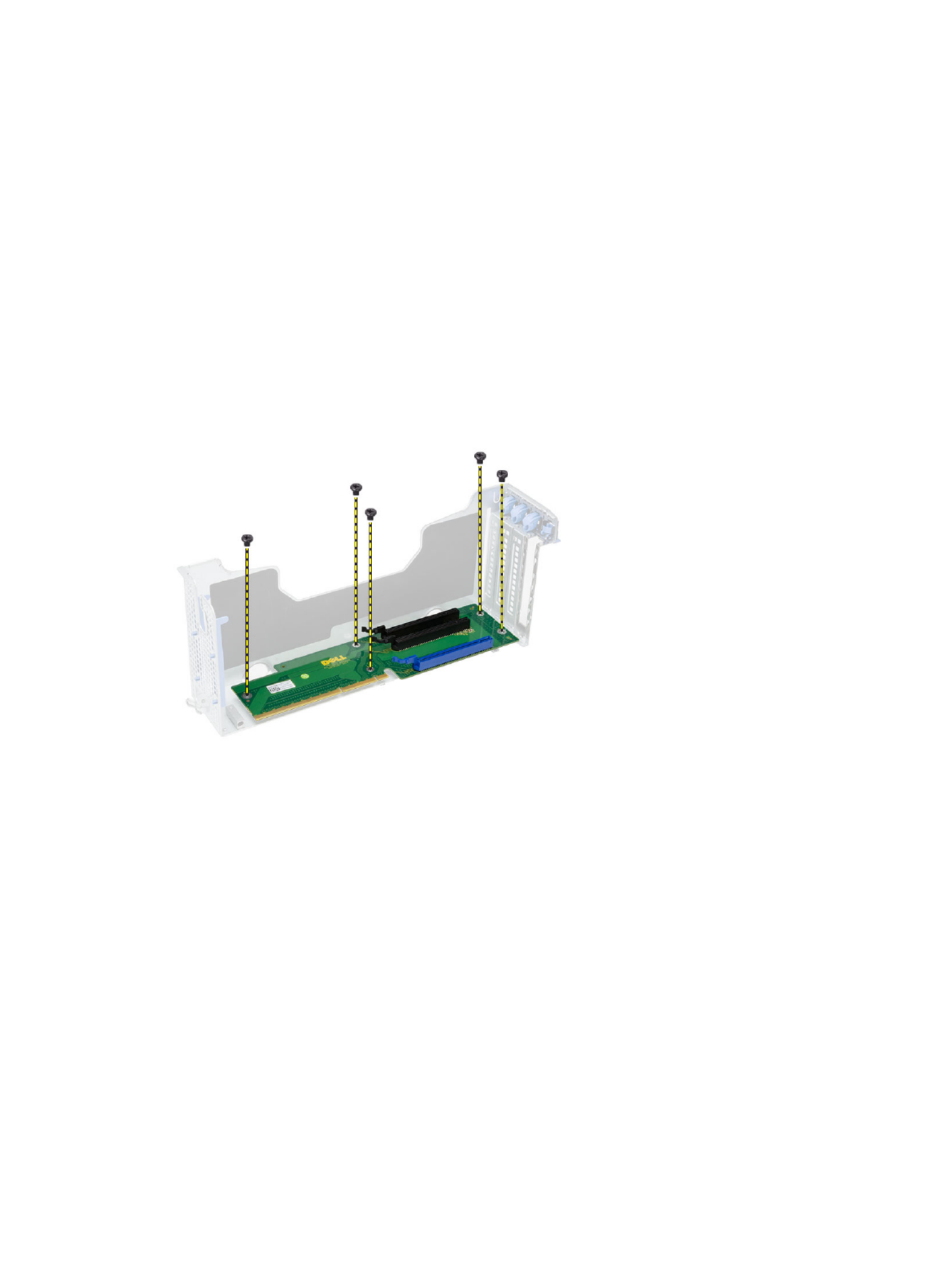
41
41
41
4141
Removing the SAS Controller Card
Removing the SAS Controller Card
Removing the SAS Controller Card
Removing the SAS Controller CardRemoving the SAS Controller Card
1.
1.
1.
1.1. Follow the procedures in
Before Working Inside Your Computer
.
2.
2.
2.
2.2. Remove:
– front bezel
– cover
– expansion card cages
– remote access host card
3.
3.
3.
3.3. Remove the screws that secure the SAS controller card and remove it from the computer.
91

92
Produktspezifikationen
| Marke: | Dell |
| Kategorie: | Desktop |
| Modell: | Precision R7610 |
Brauchst du Hilfe?
Wenn Sie Hilfe mit Dell Precision R7610 benötigen, stellen Sie unten eine Frage und andere Benutzer werden Ihnen antworten
Bedienungsanleitung Desktop Dell

21 September 2024
17 September 2024
15 September 2024
5 September 2024
3 September 2024
31 August 2024
28 August 2024
28 August 2024
28 August 2024
28 August 2024
Bedienungsanleitung Desktop
- Desktop Samsung
- Desktop Acer
- Desktop Apple
- Desktop Asus
- Desktop BenQ
- Desktop Gigabyte
- Desktop HP
- Desktop Medion
- Desktop Microsoft
- Desktop Sharkoon
- Desktop Sony
- Desktop LG
- Desktop Sharp
- Desktop WOOOD
- Desktop Haier
- Desktop TrekStor
- Desktop Optoma
- Desktop PEAQ
- Desktop Toshiba
- Desktop Mio
- Desktop ViewSonic
- Desktop LC-Power
- Desktop Lenovo
- Desktop MSI
- Desktop JYSK
- Desktop Tripp Lite
- Desktop Razer
- Desktop ELO
- Desktop Targa
- Desktop Xoro
- Desktop Vtech
- Desktop Parisot
- Desktop Wehkamp
- Desktop Supermicro
- Desktop Faytech
- Desktop InFocus
- Desktop NEC
- Desktop Seagate
- Desktop Fujitsu
- Desktop Maxdata
- Desktop Packard Bell
- Desktop Kogan
- Desktop ZTE
- Desktop Atari
- Desktop Kramer
- Desktop Asrock
- Desktop ECS
- Desktop Promethean
- Desktop Vorago
- Desktop Emachines
- Desktop Ibm
- Desktop MP
- Desktop ONYX
- Desktop Alienware
- Desktop Zotac
- Desktop Intel
- Desktop Moxa
- Desktop VXL
- Desktop Planar
- Desktop Shuttle
- Desktop Altra
- Desktop Axis
- Desktop Advantech
- Desktop Elitegroup
- Desktop BDI
- Desktop Bestar
- Desktop Pelco
- Desktop Foxconn
- Desktop System76
- Desktop NComputing
- Desktop Cybernet
- Desktop Aopen
- Desktop Smart Things
- Desktop Zoostorm
- Desktop Dell Wyse
- Desktop MvixUSA
- Desktop AIS
- Desktop Wyse
Neueste Bedienungsanleitung für -Kategorien-

30 November 2024

15 Oktober 2024

14 Oktober 2024
12 Oktober 2024
11 Oktober 2024

9 Oktober 2024

9 Oktober 2024

7 Oktober 2024
4 Oktober 2024
4 Oktober 2024