Dell Inspiron 3558 Bedienungsanleitung
Lesen Sie kostenlos die 📖 deutsche Bedienungsanleitung für Dell Inspiron 3558 (92 Seiten) in der Kategorie Laptop. Dieser Bedienungsanleitung war für 13 Personen hilfreich und wurde von 2 Benutzern mit durchschnittlich 4.5 Sternen bewertet
Seite 1/92

Inspiron 15
3000 Series
Service Manual
Computer Model: Inspiron 15–3558
Regulatory Model: P47F
Regulatory Type: P47F002

Notes, Cautions, and Warnings
NOTE:
NOTE:
NOTE:
NOTE: NOTE: A NOTE indicates important information that helps you make better
use of your computer.
CAUTION: A CAUTION indicates either potential damage to hardware or loss
of data and tells you how to avoid the problem.
WARNING: A WARNING indicates a potential for property damage, personal
injury, or death.
Copyright 2015 Dell Inc. All rights reserved.© This product is protected by U.S. and
international copyright and intellectual property laws. Dell™ and the Dell logo are trademarks
of Dell Inc. in the United States and/or other jurisdictions. All other marks and names
mentioned herein may be trademarks of their respective companies.
2015–01
Rev. A00

Contents
Before working inside your computer.....................................9
Before you begin ...............................................................................................9
Safety instructions..............................................................................................9
Recommended tools....................................................................................... 10
After working inside your computer......................................12
Removing the battery............................................................... 13
Procedure.........................................................................................................13
Replacing the battery............................................................... 14
Procedure.........................................................................................................14
Removing the base panel.........................................................15
Prerequisites..................................................................................................... 15
Procedure.........................................................................................................15
Replacing the base panel......................................................... 16
Procedure.........................................................................................................16
Post-requisites................................................................................................. 16
Removing the hard drive.......................................................... 17
Prerequisites..................................................................................................... 17
Procedure......................................................................................................... 17
Replacing the hard drive.......................................................... 21
Procedure.........................................................................................................21
Post-requisites................................................................................................. 21

Removing the memory modules............................................ 22
Prerequisites.....................................................................................................22
Procedure.........................................................................................................22
Replacing the memory modules............................................ 24
Procedure........................................................................................................ 24
Post-requisites................................................................................................. 25
Removing the wireless card.................................................... 26
Prerequisites.....................................................................................................26
Procedure........................................................................................................ 26
Replacing the wireless card.....................................................28
Procedure........................................................................................................ 28
Post-requisites................................................................................................. 28
Removing the keyboard...........................................................29
Prerequisites.....................................................................................................29
Procedure........................................................................................................ 29
Replacing the keyboard........................................................... 32
Procedure.........................................................................................................32
Post-requisites................................................................................................. 32
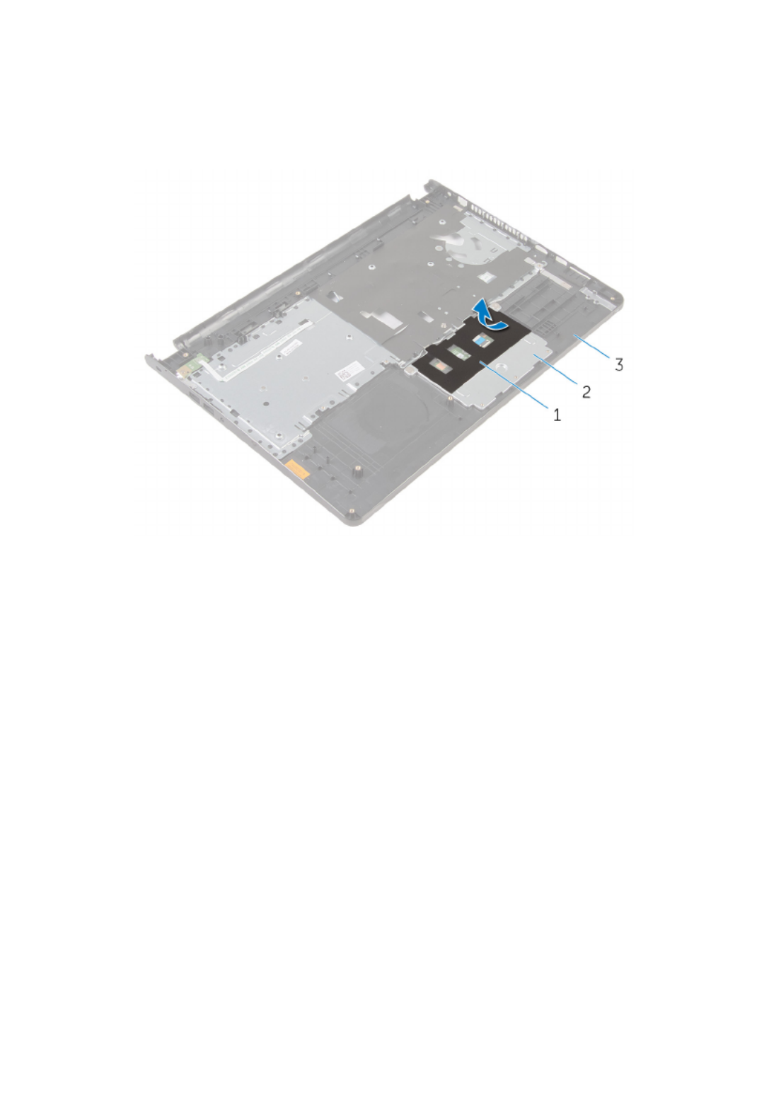
Removing the palm rest........................................................... 33
Prerequisites.....................................................................................................33
Procedure.........................................................................................................33
Replacing the palm rest........................................................... 38
Procedure........................................................................................................ 38
Post-requisites................................................................................................. 38

Removing the touch pad......................................................... 39
Prerequisites.....................................................................................................39
Procedure........................................................................................................ 40
Replacing the touch pad..........................................................43
Procedure........................................................................................................ 43
Post-requisites................................................................................................. 43
Removing the power-button board...................................... 44
Prerequisites.................................................................................................... 44
Procedure........................................................................................................ 45
Replacing the power-button board.......................................47
Procedure.........................................................................................................47
Post-requisites................................................................................................. 47
Removing the speakers............................................................48
Prerequisites.................................................................................................... 48
Procedure........................................................................................................ 49
Replacing the speakers.............................................................51
Procedure......................................................................................................... 51
Post-requisites................................................................................................. 51
Removing the I/O board.......................................................... 52
Prerequisites.....................................................................................................52
Procedure.........................................................................................................52
Replacing the I/O board...........................................................54
Procedure........................................................................................................ 54
Post-requisites................................................................................................. 54

Removing the system board....................................................55
Prerequisites.....................................................................................................55
Procedure........................................................................................................ 56
Replacing the system board....................................................59
Procedure........................................................................................................ 59
Post-requisites.................................................................................................60
Removing the coin-cell battery..............................................61
Prerequisites.....................................................................................................61
Procedure.........................................................................................................61
Replacing the coin-cell battery.............................................. 63
Procedure........................................................................................................ 63
Post-requisites................................................................................................. 63
Removing the heat sink............................................................64
Prerequisites.................................................................................................... 64
Procedure........................................................................................................ 64
Replacing the heat sink............................................................66
Procedure........................................................................................................ 66
Post-requisites.................................................................................................66
Removing the fan...................................................................... 67
Prerequisites.....................................................................................................67
Procedure........................................................................................................ 68
Replacing the fan...................................................................... 69
Procedure........................................................................................................ 69
Post-requisites.................................................................................................69

Removing the display assembly..............................................70
Prerequisites.....................................................................................................70
Procedure........................................................................................................ 70
Replacing the display assembly.............................................. 73
Procedure.........................................................................................................73
Post-requisites................................................................................................. 73
Removing the power-adapter port........................................74
Prerequisites.....................................................................................................74
Procedure.........................................................................................................74
Replacing the power-adapter port........................................ 76
Procedure.........................................................................................................76
Post-requisites................................................................................................. 76
Removing the display bezel.....................................................77
Prerequisites..................................................................................................... 77
Procedure.........................................................................................................78
Replacing the display bezel.....................................................79
Procedure.........................................................................................................79
Post-requisites................................................................................................. 79
Removing the display panel.................................................... 80
Prerequisites.................................................................................................... 80
Procedure........................................................................................................ 80
Replacing the display panel.....................................................83
Procedure........................................................................................................ 83
Post-requisites.................................................................................................83

Removing the camera.............................................................. 84
Prerequisites.................................................................................................... 84
Procedure........................................................................................................ 84
Replacing the camera...............................................................86
Post-requisites.................................................................................................86
Procedure........................................................................................................ 86
Removing the display hinges.................................................. 87
Prerequisites.....................................................................................................87
Procedure.........................................................................................................87
Replacing the display hinges.................................................. 89
Procedure........................................................................................................ 89
Post-requisites.................................................................................................89
Flashing the BIOS...................................................................... 90
Getting help and contacting Dell........................................... 91
Self-help resources..........................................................................................91
Contacting Dell................................................................................................ 91

Before working inside your
computer
CAUTION: To avoid damaging the components and cards, handle
them by their edges and avoid touching pins and contacts.
NOTE:
NOTE:
NOTE:
NOTE: NOTE: The images in this document may differ from your computer
depending on the configuration you ordered.
Before you begin
1 Save and close all open files and exit all open applications.
2 Shut down your computer.
– Windows 8.1: On the screen, click or tap the power icon Start →
Shut down.
– Windows 7: Click or tap .Start Shut down→
NOTE:
NOTE:
NOTE:
NOTE: NOTE: If you are using a different operating system, see the
documentation of your operating system for shut-down
instructions.
3 Disconnect your computer and all attached devices from their electrical
outlets.
4 Disconnect all cables such as telephone cables, network cables and so
on, from your computer.
5 Disconnect all attached devices and peripherals, such as keyboard,
mouse, monitor, and so on, from your computer.
6 Remove any media card and optical disc from your computer, if
applicable.
Safety instructions
Use the following safety guidelines to protect your computer from potential
damage and ensure your personal safety.
9

WARNING: Before working inside your computer, read the safety
information that shipped with your computer. For more safety best
practices, see the Regulatory Compliance home page at dell.com/
regulatory_compliance.
WARNING: Disconnect all power sources before opening the
computer cover or panels. After you finish working inside the
computer, replace all covers, panels, and screws before connecting to
the power source.
CAUTION: To avoid damaging the computer, ensure that the work
surface is flat and clean.
CAUTION: To avoid damaging the components and cards, handle
them by their edges and avoid touching pins and contacts.
CAUTION: You should only perform troubleshooting and repairs as
authorized or directed by the Dell technical assistance team. Damage
due to servicing that is not authorized by Dell is not covered by your
warranty. See the safety instructions that shipped with the product or
at dell.com/regulatory_compliance.
CAUTION: Before touching anything inside your computer, ground
yourself by touching an unpainted metal surface, such as the metal at
the back of the computer. While you work, periodically touch an
unpainted metal surface to dissipate static electricity, which could
harm internal components.
CAUTION: When you disconnect a cable, pull on its connector or on
its pull-tab, not on the cable itself. Some cables have connectors with
locking tabs or thumb-screws that you must disengage before
disconnecting the cable. When disconnecting cables, keep them
evenly aligned to avoid bending any connector pins. When connecting
cables, ensure that the ports and connectors are correctly oriented
and aligned.
CAUTION: To disconnect a network cable, first unplug the cable from
your computer and then unplug the cable from the network device.
CAUTION: Press and eject any installed card from the media-card
reader.
Recommended tools
The procedures in this document may require the following tools:
10

• Philips screwdriver
• Plastic scribe
11

After working inside your
computer
CAUTION: Leaving stray or loose screws inside your computer may
severely damage your computer.
1 Replace all screws and ensure that no stray screws remain inside your
computer.
2 Connect any external devices, peripherals, and cables you removed
before working on your computer.
3 Replace any media cards, discs, and any other parts that you removed
before working on your computer.
4 Connect your computer and all attached devices to their electrical
outlets.
5 Turn on your computer.
12

Removing the battery
WARNING: Before working inside your computer, read the safety
information that shipped with your computer and follow the steps in
Before working inside your computer. After working inside your
computer, follow the instructions in After working inside your
computer. For more safety best practices, see the Regulatory
Compliance home page at dell.com/regulatory_compliance.
Procedure
1 Close the display and turn the computer over.
2 Slide the battery-release latch to the unlock position.
3 Lift the battery at an angle and remove the battery from the battery bay.
1 battery 2 battery-release latch
4 Turn the computer over, open the display, and press the power button
for five seconds to ground the system board.
13

Replacing the battery
WARNING: Before working inside your computer, read the safety
information that shipped with your computer and follow the steps in
Before working inside your computer. After working inside your
computer, follow the instructions in After working inside your
computer. For more safety best practices, see the Regulatory
Compliance home page at dell.com/regulatory_compliance.
Procedure
Slide the tabs on the battery into the slots on the battery bay and snap the
battery into place.
NOTE:
NOTE:
NOTE:
NOTE: NOTE: The battery-release latch returns to the lock position if the
battery is installed properly.
14

Removing the base panel
WARNING: Before working inside your computer, read the safety
information that shipped with your computer and follow the steps in
Before working inside your computer. After working inside your
computer, follow the instructions in After working inside your
computer. For more safety best practices, see the Regulatory
Compliance home page at dell.com/regulatory_compliance.
Prerequisites
Remove the .battery
Procedure
1 Remove the screws that secure the base panel to the computer base.
2 Using your fingertips, gently pry the base panel off the computer base.
1 computer base 2 screws (2)
3 base panel
15

Replacing the base panel
WARNING: Before working inside your computer, read the safety
information that shipped with your computer and follow the steps in
Before working inside your computer. After working inside your
computer, follow the instructions in After working inside your
computer. For more safety best practices, see the Regulatory
Compliance home page at dell.com/regulatory_compliance.
Procedure
1 Slide the tabs on the base panel into the slots on the computer base and
snap the base panel into place.
2 Replace the screws that secure the base panel to the computer base.
Post-requisites
Replace the .battery
16

Removing the hard drive
WARNING: Before working inside your computer, read the safety
information that shipped with your computer and follow the steps in
Before working inside your computer. After working inside your
computer, follow the instructions in After working inside your
computer. For more safety best practices, see the Regulatory
Compliance home page at dell.com/regulatory_compliance.
CAUTION: Hard drives are fragile. Exercise care when handling the
hard drive.
CAUTION: To avoid data loss, do not remove the hard drive while the
computer is in sleep or on state.
Prerequisites
1 Remove the .battery
2 Remove the .base panel
Procedure
1 Remove the screws that secure the hard-drive assembly to the computer
base.
2 Lift the latch and disconnect the hard-drive cable from the system board.
17

3 Lift the hard-drive assembly off the computer base.
1 screws (4) 2 hard-drive assembly
3 hard-drive cable 4 latch
18

4 Disconnect the interposer from the hard drive.
1 hard-drive assembly 2 interposer
19

5 Remove the screws that secure the hard-drive bracket to the hard drive
and lift the hard-drive bracket off the hard drive.
1 screws (4) 2 hard-drive bracket
3 hard drive
20

Replacing the hard drive
WARNING: Before working inside your computer, read the safety
information that shipped with your computer and follow the steps in
Before working inside your computer. After working inside your
computer, follow the instructions in After working inside your
computer. For more safety best practices, see the Regulatory
Compliance home page at dell.com/regulatory_compliance.
CAUTION: Hard drives are fragile. Exercise care when handling the
hard drive.
Procedure
1 Place the hard-drive bracket over the hard drive and align the screw
holes on the hard-drive bracket with the screw holes on the hard drive.
2 Replace the screws that secure the hard-drive bracket to the hard drive.
3 Slide the hard-drive assembly in the computer base and align the screw
holes on the hard-drive assembly with the screw holes on the computer
base.
4 Connect the hard-drive cable to the hard drive.
5 Replace the screws that secure the hard-drive assembly to the computer
base.
Post-requisites
1 Replace the .base panel
2 Replace the .battery
21

Removing the memory
modules
WARNING: Before working inside your computer, read the safety
information that shipped with your computer and follow the steps in
Before working inside your computer. After working inside your
computer, follow the instructions in After working inside your
computer. For more safety best practices, see the Regulatory
Compliance home page at dell.com/regulatory_compliance.
Prerequisites
1 Remove the .battery
2 Remove the .base panel
Procedure
1 Using your fingertips, pry apart the securing clips on each end of the
memory-module slot until the memory module pops up.
22

2 Slide and remove the memory module from the memory-module slot.
1 securing clips 2 memory module
23

Replacing the memory
modules
WARNING: Before working inside your computer, read the safety
information that shipped with your computer and follow the steps in
Before working inside your computer. After working inside your
computer, follow the instructions in After working inside your
computer. For more safety best practices, see the Regulatory
Compliance home page at dell.com/regulatory_compliance.
Procedure
1 Align the notch on the memory module with the tab on the memory-
module slot.
24

2 Slide the memory module firmly into the slot at an angle and press the
memory module down until it clicks into place.
NOTE:
NOTE:
NOTE:
NOTE: NOTE: If you do not hear the click, remove the memory module
and reinstall it.
1 notch 2 memory module
3 securing clips 4 tab
Post-requisites
1 Replace the .base panel
2 Replace the .battery
25

Removing the wireless card
WARNING: Before working inside your computer, read the safety
information that shipped with your computer and follow the steps in
Before working inside your computer. After working inside your
computer, follow the instructions in After working inside your
computer. For more safety best practices, see the Regulatory
Compliance home page at dell.com/regulatory_compliance.
Prerequisites
1 Remove the .battery
2 Remove the .base panel
Procedure
1 Disconnect the antenna cables from the wireless card.
2 Remove the screw that secures the wireless card to the system board.
26

3 Lift the wireless card, and then slide and remove it from the system
board.
1 antenna cables (2) 2 wireless card
3 screw 4 notch
5 tab
27

Replacing the wireless card
WARNING: Before working inside your computer, read the safety
information that shipped with your computer and follow the steps in
Before working inside your computer. After working inside your
computer, follow the instructions in After working inside your
computer. For more safety best practices, see the Regulatory
Compliance home page at dell.com/regulatory_compliance.
Procedure
CAUTION: To avoid damage to the wireless card, do not place any
cables under it.
1 Align the notch on the wireless card with the tab on the wireless-card
slot and slide the card into the slot.
2 Replace the screw that secures the wireless card to the system board.
3 Connect the antenna cables to the wireless card. The following table
provides the antenna-cable color scheme for the wireless card supported
by your computer:
Connectors on the wireless card Antenna-cable color
Main (white triangle) White
Auxiliary (black triangle) Black
Post-requisites
1 Replace the .base panel
2 Replace the .battery
28

Removing the keyboard
WARNING: Before working inside your computer, read the safety
information that shipped with your computer and follow the steps in
Before working inside your computer. After working inside your
computer, follow the instructions in After working inside your
computer. For more safety best practices, see the Regulatory
Compliance home page at dell.com/regulatory_compliance.
Prerequisites
Remove the .battery
Procedure
1 Turn the computer over and open the display as far as possible.
29

2 Using a plastic scribe, gently release the tabs that secure the keyboard to
the palm-rest assembly.
1 tab 2 plastic scribe
3 keyboard 4 palm-rest assembly
3 Carefully turn the keyboard over and place it on the palm-rest assembly.
30

4 Lift the latches and disconnect the keyboard cable and the keyboard-
backlight cable from the system board.
NOTE:
NOTE:
NOTE:
NOTE: NOTE: The keyboard-backlight cable is present only if the laptop
shipped with a backlit keyboard.
1 latch 2 keyboard cable
3 keyboard 4 palm-rest assembly
5 Lift the keyboard, along with the cables, off the palm-rest assembly.
31

Replacing the keyboard
WARNING: Before working inside your computer, read the safety
information that shipped with your computer and follow the steps in
Before working inside your computer. After working inside your
computer, follow the instructions in After working inside your
computer. For more safety best practices, see the Regulatory
Compliance home page at dell.com/regulatory_compliance.
Procedure
1 Slide the keyboard cable into the system-board slot and press down on
the latch to secure the cable.
2 Carefully turn the keyboard over, slide the tabs on the keyboard into the
slots on the palm rest, and snap the keyboard into place.
3 Close the display and turn the computer over.
Post-requisites
Replace the .battery
32

Removing the palm rest
WARNING: Before working inside your computer, read the safety
information that shipped with your computer and follow the steps in
Before working inside your computer. After working inside your
computer, follow the instructions in After working inside your
computer. For more safety best practices, see the Regulatory
Compliance home page at dell.com/regulatory_compliance.
Prerequisites
1 Remove the .battery
2 Remove the .base panel
3 Follow the procedure from step 1 to step 3 in “Removing the ”.hard drive
4 Remove the .keyboard
Procedure
1 Lift the latch and disconnect the touch-pad cable from the system board.
2 Lift the latch and disconnect the power-button cable from the system
board.
33

5 Remove the screws that secure the palm-rest assembly to the computer
base.
1 screws (10) 2 computer base
35

6 Slightly open the computer base and, using a plastic scribe, pry the palm-
rest assembly off the computer base.
1 computer base 2 palm-rest assembly
3 plastic scribe
7 Turn the computer over and open the display.
36

8 Lift the palm-rest assembly off the computer base.
1 palm-rest assembly 2 computer base
9 Follow the procedure from step 1 to step 5 in “Removing the ”.touch pad
37

Replacing the palm rest
WARNING: Before working inside your computer, read the safety
information that shipped with your computer and follow the steps in
Before working inside your computer. After working inside your
computer, follow the instructions in After working inside your
computer. For more safety best practices, see the Regulatory
Compliance home page at dell.com/regulatory_compliance.
Procedure
1 Follow the procedure from step 1 to step 5 in “Replacing the ”.touch pad
2 Align the screw holes on the palm rest with the screw holes on the
computer base and snap the palm rest into place.
3 Replace the screws that secure the palm rest to the computer base.
4 Slide the touch pad cable and the power-button cable into the respective
connectors and press down on the latches to secure the cables.
5 Turn the computer over.
6 Replace the screws that secure the palm rest to the back cover.
Post-requisites
1 Replace the .keyboard
2 Follow the procedure from step 3 to step 5 in “Replacing the ”.hard drive
3 Replace the .base panel
4 Replace the .battery
38

Removing the touch pad
WARNING: Before working inside your computer, read the safety
information that shipped with your computer and follow the steps in
Before working inside your computer. After working inside your
computer, follow the instructions in After working inside your
computer. For more safety best practices, see the Regulatory
Compliance home page at dell.com/regulatory_compliance.
Prerequisites
1 Remove the .battery
2 Remove the .base panel
3 Follow the procedure from step 1 to step 3 in “Removing the ”.hard drive
4 Remove the .keyboard
5 Remove the .palm rest
39
Procedure
1 Peel the tape off the touch-pad bracket.
1 tape 2 touch-pad bracket
3 palm rest
2 Remove the screws that secure the touch-pad bracket to the touch pad.
40

3 Lift the latch and disconnect the touch-pad cable from touch pad.
1 touch-pad cable 2 latch
3 screws (2) 4 palm rest
5 touch-pad bracket
4 Peel off the tape over the touch pad.
41

5 Lift the touch pad off the palm rest.
1 tape 2 touch pad
3 palm rest
42

Removing the power-button
board
WARNING: Before working inside your computer, read the safety
information that shipped with your computer and follow the steps in
Before working inside your computer. After working inside your
computer, follow the instructions in After working inside your
computer. For more safety best practices, see the Regulatory
Compliance home page at dell.com/regulatory_compliance.
Prerequisites
1 Remove the .battery
2 Remove the .base panel
3 Follow the procedure from step 1 to step 3 in “Removing the ”.hard drive
4 Remove the .keyboard
5 Follow the procedure from step 1 to step 8 in “Removing the ”.palm rest
44

Procedure
1 Slide the power-button board cable through the slot on the palm rest.
1 power-button board cable 2 slot
3 palm rest
2 Turn the palm rest over.
3 Remove the screw that secures the power-button board to the palm rest.
4 Slide the power-button board out from the tab on the palm rest.
45

Replacing the power-button
board
WARNING: Before working inside your computer, read the safety
information that shipped with your computer and follow the steps in
Before working inside your computer. After working inside your
computer, follow the instructions in After working inside your
computer. For more safety best practices, see the Regulatory
Compliance home page at dell.com/regulatory_compliance.
Procedure
1 Slide the power-button board under the tab on the palm rest and align
the screw hole on the power-button board with the screw hole on the
palm rest.
2 Replace the screw that secures the power-button board to the palm rest.
3 Slide the power-button board cable through the slot on the palm rest.
Post-requisites
1 Follow the procedure from step 2 to step 6 in “Replacing the ”.palm rest
2 Replace the .keyboard
3 Follow the procedure from step 4 to step 6 in “Replacing the ”.hard drive
4 Replace the .base panel
5 Replace the .battery
47

Procedure
1 Disconnect the speaker cable from the system board.
1 speaker cable 2 slot
2 Turn the computer over and open the display.
3 Note the speaker-cable routing and remove the cable from the routing
guides on the computer base.
49

4 Slide the speaker cable through the slot on the computer base and lift the
speakers, along with the speaker cable, off the computer base .
1 speaker cable 2 speakers (2)
50

Replacing the speakers
WARNING: Before working inside your computer, read the safety
information that shipped with your computer and follow the steps in
Before working inside your computer. After working inside your
computer, follow the instructions in After working inside your
computer. For more safety best practices, see the Regulatory
Compliance home page at dell.com/regulatory_compliance.
Procedure
1 Using the alignment posts, align and place the speakers on the palm rest.
2 Route the speaker cable through the routing guides on the palm rest.
3 Turn the computer over.
4 Slide the speaker cable through the slot on the computer base and
connect the speaker cable to the system board.
Post-requisites
1 Follow the procedure from step 2 to step 6 in “Replacing the ”.palm rest
2 Replace the .keyboard
3 Follow the procedure from step 3 to step 5 in “Replacing the ”.hard drive
4 Replace the .base panel
5 Replace the .battery
51

Removing the I/O board
WARNING: Before working inside your computer, read the safety
information that shipped with your computer and follow the steps in
Before working inside your computer. After working inside your
computer, follow the instructions in After working inside your
computer. For more safety best practices, see the Regulatory
Compliance home page at dell.com/regulatory_compliance.
Prerequisites
1 Remove the .battery
2 Remove the .base panel
3 Follow the procedure from step 1 to step 3 in “Removing the ”.hard drive
4 Remove the .keyboard
5 Follow the procedure from step 1 to step 8 in “Removing the ”.palm rest
Procedure
1 Lift the latch and disconnect the I/O-board cable from the I/O board.
2 Remove the screw that secures the I/O board to the computer base.
52

3 Lift the I/O board off the computer base.
1 screw 2 I/O board
3 latch 4 I/O-board cable
53
Produktspezifikationen
| Marke: | Dell |
| Kategorie: | Laptop |
| Modell: | Inspiron 3558 |
| Touchscreen: | Nein |
| Bildschirmdiagonale: | 15.6 " |
| Eingebautes Mikrofon: | Ja |
| Installiertes Betriebssystem: | Windows 8.1 |
| Prozessorhersteller: | Intel |
| Anzahl Prozessorkerne: | 2 |
| WLAN: | Ja |
| WLAN-Standards: | 802.11b, 802.11g, Wi-Fi 4 (802.11n) |
| Bluetooth: | Ja |
| Bluetooth-Version: | 4.0 |
| Akku-/Batteriebetriebsdauer: | - h |
| Breite: | 380 mm |
| Tiefe: | 260.3 mm |
| Gewicht: | 2190 g |
| AC-Netzadapter: | Ja |
| Produkttyp: | Laptop |
| Produktfarbe: | Schwarz |
| Akkuladezeit: | 4 h |
| Akku-/Batterietechnologie: | Lithium-Ion (Li-Ion) |
| Höhe: | 21.7 mm |
| Anzahl eingebauter Lautsprecher: | 2 |
| Anzahl USB 2.0 Anschlüsse: | 2 |
| Betriebstemperatur: | 0 - 35 °C |
| Relative Luftfeuchtigkeit in Betrieb: | 10 - 90 % |
| Netzteil Ausgangsspannung: | 19.5 V |
| AC-Adapter Ausgangssstrom: | 3.34 A |
| Netzteil Eingansgsspannung: | 100 - 240 V |
| Frontkamera: | Ja |
| Anzahl Ethernet-LAN-Anschlüsse (RJ-45): | 1 |
| Betriebsanleitung: | Ja |
| Natives Seitenverhältnis: | 16:9 |
| Anzahl HDMI-Anschlüsse: | 1 |
| Ethernet LAN Datentransferraten: | 10, 100 Mbit/s |
| Temperaturbereich bei Lagerung: | -40 - 65 °C |
| Luftfeuchtigkeit bei Lagerung: | 0 - 95 % |
| Audio-System: | MaxxAudio |
| DVI Anschluss: | Nein |
| Intel® Wireless-Display (Intel® WiDi): | Ja |
| Akku-/Batteriespannung: | 14.8 V |
| Mikrofon-Eingang: | Nein |
| Netzteilfrequenz: | 50 - 60 Hz |
| Kabelsperre-Slot: | Ja |
| Slot-Typ Kabelsperre: | Kensington |
| Batteriekapazität: | 40 Wh |
| Formfaktor: | Klappgehäuse |
| Prozessor-Taktfrequenz: | 2.2 GHz |
| Prozessorfamilie: | Intel® Core™ i5 |
| Prozessor: | i5-5200U |
| Kompatible Speicherkarten: | SD, SDHC, SDXC |
| Auflösung Frontkamera (numerisch): | 0.92 MP |
| Speicherkapazität: | 4 GB |
| USB 3.2 Gen 1 (3.1 Gen 1) Anzahl der Anschlüsse vom Typ A: | 1 |
| Prozessor-Cache: | 3 MB |
| Prozessor Boost-Frequenz: | 2.7 GHz |
| Konfliktloser-Prozessor: | Ja |
| Graphics & IMC lithography: | 14 nm |
| Frontsidebus des Prozessors: | - MHz |
| Prozessor Cache Typ: | Smart Cache |
| Prozessor-Code: | SR23Y |
| Prozessor Codename: | Broadwell |
| Prozessor Lithografie: | 14 nm |
| Prozessorbetriebsmodi: | 32-bit, 64-bit |
| Prozessor-Paketgröße: | 40 x 24 x 1.3 mm |
| Prozessor-Threads: | 4 |
| Stepping: | F0 |
| Systembus-Rate: | 5 GT/s |
| Thermal Design Power (TDP): | 15 W |
| Prozessor-Serien: | Intel® Core™ i5-5200-Mobile-Serie |
| Intel® Virtualisierungstechnik (Intel® VT): | VT-d, VT-x |
| Prozessorsockel: | BGA 1168 |
| ARK Prozessorerkennung: | 85212 |
| Interner Speichertyp: | DDR3L-SDRAM |
| Integrierter Kartenleser: | Ja |
| Intel® Turbo-Boost-Technologie: | 2.0 |
| Eingebettete Optionen verfügbar: | Nein |
| Intel® 64: | Ja |
| Intel® Virtualization Technologie (VT-X): | Ja |
| RAM-Speicher maximal: | 8 GB |
| HDMI-Version: | 1.4a |
| Nachhaltigkeitszertifikate: | EPEAT Bronze, ENERGY STAR |
| LED-Hintergrundbeleuchtung: | Ja |
| Wi-Fi Datenrate (max): | 300 Mbit/s |
| HDD Kapazität: | 1000 GB |
| HDD Geschwindigkeit: | 5400 RPM |
| HDD Größe: | 2.5 " |
| Passwortschutz: | Ja |
| Speichermedien: | HDD |
| Gesamtspeicherkapazität: | 1000 GB |
| Kombinierter Kopfhörer-/Mikrofon-Anschluss: | Ja |
| SmartCard-Slot: | Nein |
| Höhe bei Betrieb: | -15.2 - 3048 m |
| Intel® Small-Business-Advantage (Intel® SBA): | Ja |
| Intel® Hyper-Threading-Technik (Intel® HT Technology): | Ja |
| Intel® Identity-Protection-Technologie (Intel® IPT): | Ja |
| Intel® Smart-Response-Technologie: | Ja |
| Verbesserte Intel SpeedStep Technologie: | Ja |
| PCI-Express-Slots-Version: | 2.0 |
| Tjunction: | 105 °C |
| PCI Express Konfigurationen: | 4x1, 2x4 |
| Maximale Anzahl der PCI-Express-Lanes: | 12 |
| Prozessorgeneration: | Intel® Core™ i5 der fünften Generation |
| On-Board Grafikadaptermodell: | Intel® HD Graphics 5500 |
| Eingebaute Grafikadapter: | Ja |
| Dediziertes Grafikadaptermodell: | Nicht verfügbar |
| Separater Grafikadapter: | Nein |
| On-Board Grafikadapter Basisfrequenz: | 300 MHz |
| Maximale dynamische Frequenz der On-Board Grafikadapter: | 900 MHz |
| On-Board Grafikadapter Geräte-ID: | 0x1616 |
| Maximaler integrierter Grafik-Adapterspeicher: | 16 GB |
| On-Board Grafikadapter DirectX Version: | 11.2 |
| On-Board-Grafikadapterfamilie: | Intel® HD Graphics |
| Speichertaktfrequenz: | 1600 MHz |
| Speicherkartensteckplätze: | 2x SO-DIMM |
| Speicherlayout: | 1 x 4 GB |
| Anzahl der installierten HDDs: | 1 |
| Optisches Laufwerk - Typ: | Nein |
| Betriebssystemsarchitektur: | 64-Bit |
| S/PDIF-Ausgang: | Nein |
| Netzkabel enthalten: | Ja |
| Unterstützte Befehlssätze: | AVX 2.0, SSE4.1, SSE4.2 |
| Intel® Quick-Sync-Video-Technik: | Ja |
| Intel® InTru™ 3D Technologie: | Ja |
| Intel® Clear Video HD Technology für (Intel® CVT HD): | Ja |
| Intel® AES New Instructions (Intel® AES-NI): | Ja |
| Execute Disable Bit: | Ja |
| Leerlauf Zustände: | Ja |
| Thermal-Überwachungstechnologien: | Ja |
| Intel® Trusted-Execution-Technik: | Nein |
| CPU Konfiguration (max): | 1 |
| Intel® VT-x mit Extended Page Tables (EPT): | Ja |
| Intel® Sicherer Schlüssel: | Ja |
| Intel® OS Guard: | Ja |
| Intel® Virtualisierungstechnik für direkte I/O (VT-d): | Ja |
| Intel® Clear Video Technologie: | Ja |
| Pixel Abstand: | 0.2520 x 0.2520 mm |
| Bus Typ: | DMI2 |
| ECC vom Prozessor unterstützt: | Nein |
| FSB Gleichwertigkeit: | Nein |
| HDD Schnittstelle: | SATA |
| Intel® My-WiFi-Technik (Intel® MWT): | Nein |
| Intel® Anti-Theft Technologie (Intel® AT): | Nein |
| Intel® Insider™: | Ja |
| Intel® Flex Memory Access: | Ja |
| Intel® Enhanced Halt State: | Ja |
| Intel® Demand Based Switching: | Nein |
| Intel® Clear Video Technology für Mobile Internet Devices (Intel® CVT for MID): | Ja |
| Intel® Identity Protection Technologieversion: | 1.00 |
| Intel® Secure Key Technologieversion: | 1.00 |
| Intel® Dual Display Capable Technology: | Nein |
| Intel® FDI-Technik: | Ja |
| Intel® Rapid-Storage-Technik: | Nein |
| Intel® Fast Memory Access: | Ja |
| Netzteilstärke: | 45 W |
| Docking-Connector: | Nein |
| ExpressCard-Slot: | Nein |
| CardBus PCMCIA Slot-Typ: | Nein |
| Typ Ladeanschluss: | DC-Anschluss |
| Eingabegerät: | Touchpad |
| Numerisches Keypad: | Ja |
| Intel® Smart-Connect-Technik: | Nein |
| Intel® Rapid-Start-Technologie: | Nein |
| Intel® Matrix-Storage-Technik (Intel® MST): | Nein |
| Intel HD-Audio-Technik: | Nein |
| Intel® Active Management Technologie (Intel® AMT): | Nein |
| Anzahl Batteriezellen: | 4 |
| Memory Formfaktor: | SO-DIMM |
| Intel® Small Business Advantage (SBA) Version: | 1.00 |
| Intel® Smart Response Technologieversion: | 1.00 |
| Spritzwassergeschützte Tastatur: | Ja |
| TDP-down konfigurierbar: | 7.5 W |
| TDP-down Frequenz konfigurierbar: | 0.6 GHz |
| Lautsprecher Hersteller: | Waves |
| Lautsprecher Leistung: | 2 W |
| Windows Tasten: | Ja |
| Full-size Tastatur: | Ja |
| Auflösung Frontkamera: | 1280 x 720 Pixel |
| Stoßfest (in Betrieb): | 110 G |
| Stoßfest (außer Betrieb): | 160 G |
| Höhe bei Lagerung: | -15.2 - 10668 m |
| RAM-Speicher maximal (64-bit): | 8 GB |
| LightScribe: | Nein |
| Intel® Segmentkennzeichnung: | Homeoffice |
| Testsoftware: | Microsoft Office |
| WiFi-zertifiziert: | Ja |
| Vibrationen in Betrieb: | 0.66 G |
| Vibrationen außer Betrieb: | 1.3 G |
| Display-Auflösung: | 1366 x 768 Pixel |
| Ethernet/LAN: | Ja |
Brauchst du Hilfe?
Wenn Sie Hilfe mit Dell Inspiron 3558 benötigen, stellen Sie unten eine Frage und andere Benutzer werden Ihnen antworten
Bedienungsanleitung Laptop Dell

10 Oktober 2024
6 Oktober 2024
4 Oktober 2024
17 September 2024
14 September 2024
9 September 2024
6 September 2024
6 September 2024
6 September 2024
6 September 2024
Bedienungsanleitung Laptop
- Laptop Samsung
- Laptop Acer
- Laptop Apple
- Laptop Asus
- Laptop Gigabyte
- Laptop HP
- Laptop Lexibook
- Laptop Medion
- Laptop Microsoft
- Laptop SilverCrest
- Laptop Sony
- Laptop Panasonic
- Laptop LG
- Laptop Denver
- Laptop Thomson
- Laptop BEKO
- Laptop Schneider
- Laptop Pyle
- Laptop Haier
- Laptop Coby
- Laptop Mpman
- Laptop ODYS
- Laptop Jay-Tech
- Laptop PEAQ
- Laptop Xiaomi
- Laptop Hannspree
- Laptop Hyundai
- Laptop Toshiba
- Laptop GOCLEVER
- Laptop Prixton
- Laptop ViewSonic
- Laptop Lenovo
- Laptop MSI
- Laptop Tripp Lite
- Laptop Razer
- Laptop Targa
- Laptop Zebra
- Laptop Honor
- Laptop ADATA
- Laptop NEC
- Laptop Hercules
- Laptop Fellowes
- Laptop Airis
- Laptop Fujitsu
- Laptop Huawei
- Laptop Maxdata
- Laptop Packard Bell
- Laptop Aplic
- Laptop Kogan
- Laptop Sylvania
- Laptop SPC
- Laptop Asrock
- Laptop ECS
- Laptop Hähnel
- Laptop Oregon Scientific
- Laptop Emachines
- Laptop Ematic
- Laptop Evga
- Laptop Ibm
- Laptop Micromax
- Laptop Olidata
- Laptop Vizio
- Laptop Alienware
- Laptop Siig
- Laptop Inovia
- Laptop Getac
- Laptop XPG
- Laptop Atdec
- Laptop Vulcan
- Laptop System76
- Laptop Averatec
- Laptop Hamilton Buhl
- Laptop AORUS
- Laptop CTL
- Laptop Humanscale
- Laptop Compaq
- Laptop General Dynamics Itronix
- Laptop Everex
- Laptop Dynabook
- Laptop TechBite
- Laptop Schenker
Neueste Bedienungsanleitung für -Kategorien-

1 Dezember 2024
1 Dezember 2024
1 Dezember 2024
1 Dezember 2024

30 November 2024

16 Oktober 2024
16 Oktober 2024

15 Oktober 2024

14 Oktober 2024
13 Oktober 2024