Dell Inspiron 22 3264 Bedienungsanleitung
Lesen Sie kostenlos die 📖 deutsche Bedienungsanleitung für Dell Inspiron 22 3264 (95 Seiten) in der Kategorie Desktop. Dieser Bedienungsanleitung war für 18 Personen hilfreich und wurde von 2 Benutzern mit durchschnittlich 4.5 Sternen bewertet
Seite 1/95

Inspiron 22 3000
Service Manual
Computer Model: Inspiron 22–3264
Regulatory Model: W17B
Regulatory Type: W17B003

Notes, cautions, and warnings
NOTE:
NOTE:
NOTE:
NOTE: NOTE: A NOTE indicates important information that helps you make better
use of your product.
CAUTION: A CAUTION indicates either potential damage to hardware or loss
of data and tells you how to avoid the problem.
WARNING: A WARNING indicates a potential for property damage, personal
injury, or death.
© 2016 Dell Inc. All rights reserved. This product is protected by U.S. and international
copyright and intellectual property laws. Dell and the Dell logo are trademarks of Dell Inc. in
the United States and/or other jurisdictions. All other marks and names mentioned herein may
be trademarks of their respective companies.
2016 - 08
Rev. A00

Contents
Before working inside your computer.....................................9
Before you begin ...............................................................................................9
Safety instructions............................................................................................10
Recommended tools........................................................................................11
Screw list...........................................................................................................11
After working inside your computer......................................12
Technical overview....................................................................13
Inside view of your computer..........................................................................13
System-board components............................................................................ 14
Removing the stand.................................................................. 16
Easel stand........................................................................................................16
Pedestal stand.................................................................................................. 18
Procedure to remove stand riser from stand base................................... 19
Replacing the stand.................................................................. 22
Easel stand....................................................................................................... 22
Pedestal stand..................................................................................................22
Procedure to replace stand riser to stand base........................................22
Removing the back cover........................................................ 23
Prerequisites.....................................................................................................23
Procedure.........................................................................................................23
Replacing the back cover.........................................................25
Procedure.........................................................................................................25
Post-requisites................................................................................................. 25
3

Replacing the optical drive......................................................26
Prerequisites.....................................................................................................26
Procedure........................................................................................................ 26
Removing the optical drive..................................................... 29
Procedure........................................................................................................ 29
Post-requisites................................................................................................. 29
Removing the hard drive..........................................................30
Prerequisites.................................................................................................... 30
Procedure........................................................................................................ 30
Replacing the hard drive.......................................................... 33
Procedure.........................................................................................................33
Post-requisites................................................................................................. 33
Removing the system-board shield.......................................34
Prerequisites.....................................................................................................34
Procedure........................................................................................................ 34
Replacing the system-board shield....................................... 36
Procedure........................................................................................................ 36
Post-requisites................................................................................................. 36
Removing the memory module.............................................. 37
Prerequisites.....................................................................................................37
Procedure.........................................................................................................37
Replacing the memory module.............................................. 39
Procedure........................................................................................................ 39
Post-requisites.................................................................................................40
4

Removing the wireless card.................................................... 42
Prerequisites.....................................................................................................42
Procedure........................................................................................................ 42
Replacing the wireless card.................................................... 44
Procedure........................................................................................................ 44
Post-requisites................................................................................................. 45
Removing the control-buttons board...................................47
Prerequisites.....................................................................................................47
Procedure.........................................................................................................47
Replacing the control-buttons board...................................49
Procedure........................................................................................................ 49
Post-requisites.................................................................................................49
Removing the microphone......................................................50
Prerequisites.................................................................................................... 50
Procedure........................................................................................................ 50
Replacing the microphone...................................................... 52
Procedure.........................................................................................................52
Post-requisites................................................................................................. 52
Removing the camera...............................................................53
Prerequisites.....................................................................................................53
Procedure.........................................................................................................53
Replacing the camera............................................................... 57
Procedure.........................................................................................................57
Post-requisites................................................................................................. 57
5

Removing the coin-cell battery..............................................58
Prerequisites.....................................................................................................58
Procedure........................................................................................................ 58
Replacing the coin-cell battery..............................................60
Procedure........................................................................................................ 60
Post-requisites.................................................................................................60
Removing the fan...................................................................... 61
Prerequisites..................................................................................................... 61
Procedure.........................................................................................................61
Replacing the fan.......................................................................63
Procedure........................................................................................................ 63
Post-requisites................................................................................................. 63
Removing the heat sink............................................................64
Prerequisites.................................................................................................... 64
Procedure........................................................................................................ 64
Replacing the heat sink............................................................66
Procedure........................................................................................................ 66
Post-requisites.................................................................................................66
Removing the speakers............................................................ 67
Prerequisites.....................................................................................................67
Procedure.........................................................................................................67
Replacing the speakers............................................................ 69
Procedure........................................................................................................ 69
Post-requisites.................................................................................................69
6

BIOS setup program..................................................................87
BIOS Overview................................................................................................. 87
Entering BIOS setup program......................................................................... 87
Clearing forgotten passwords.........................................................................87
Prerequisites...............................................................................................88
Procedure.................................................................................................. 88
Post-requisites...........................................................................................88
Clearing CMOS Settings..................................................................................89
Prerequisites...............................................................................................89
Procedure.................................................................................................. 89
Post-requisites...........................................................................................90
Flashing the BIOS.......................................................................91
System diagnostic lights.......................................................... 92
Getting help and contacting Dell...........................................94
Self-help resources......................................................................................... 94
Contacting Dell................................................................................................95
8

Before working inside your
computer
NOTE:
NOTE:
NOTE:
NOTE: NOTE: The images in this document may differ from your computer
depending on the configuration you ordered.
Before you begin
1 Save and close all open files and exit all open applications.
2 Shut down your computer.
The shut-down instruction varies depending on the operating system
installed on your computer.
– Windows 10: Click .Start Power Shut down→ →
– Windows 8.1: On the screen, click the power icon Start → Shut
down.
– Windows 7: Click .Start Shut down→
NOTE:
NOTE:
NOTE:
NOTE: NOTE: If you are using a different operating system, see the
documentation of your operating system for shut-down
instructions.
3 Disconnect your computer and all attached devices from their electrical
outlets.
4 Disconnect all cables such as telephone cables, network cables, and so
on, from your computer.
5 Disconnect all attached devices and peripherals, such as keyboard,
mouse, monitor, and so on, from your computer.
6 Remove any media card and optical disc from your computer, if
applicable.
7 After the computer is unplugged, press and hold the power button for 5
seconds to ground the system board.
CAUTION: Place the computer on a flat, soft, and clean surface to
avoid scratches on the display.
8 Place the computer face down.
9

Safety instructions
Use the following safety guidelines to protect your computer from potential
damage and ensure your personal safety.
WARNING: Before working inside your computer, read the safety
information that shipped with your computer. For more safety best
practices, see the Regulatory Compliance home page at
www.dell.com/regulatory_compliance.
WARNING: Disconnect all power sources before opening the
computer cover or panels. After you finish working inside the
computer, replace all covers, panels, and screws before connecting to
the electrical outlet.
CAUTION: To avoid damaging the computer, ensure that the work
surface is flat and clean.
CAUTION: To avoid damaging the components and cards, handle
them by their edges, and avoid touching pins and contacts.
CAUTION: You should only perform troubleshooting and repairs as
authorized or directed by the Dell technical assistance team. Damage
due to servicing that is not authorized by Dell is not covered by your
warranty. See the safety instructions that shipped with the product or
at .www.dell.com/regulatory_compliance
CAUTION: Before touching anything inside your computer, ground
yourself by touching an unpainted metal surface, such as the metal at
the back of the computer. While you work, periodically touch an
unpainted metal surface to dissipate static electricity, which could
harm internal components.
CAUTION: When you disconnect a cable, pull on its connector or on
its pull tab, not on the cable itself. Some cables have connectors with
locking tabs or thumb-screws that you must disengage before
disconnecting the cable. When disconnecting cables, keep them
evenly aligned to avoid bending any connector pins. When connecting
cables, ensure that the ports and connectors are correctly oriented
and aligned.
CAUTION: Press and eject any installed card from the media-card
reader.
10

Recommended tools
The procedures in this document may require the following tools:
• Phillips screwdriver
• Plastic scribe
Screw list
Component Secured to Screw type Quantity
Easel Stand Back cover M4X8 2
Pedestal Stand Back cover M4X8 4
Optical-drive bracket Display-assembly base M3X5 1
Optical-drive bracket Optical drive M2X2.5 2
Hard-drive assembly Display-assembly base M3X5 1
Hard-drive bracket Hard drive M3X5 3
System-board shield Display-assembly base M3X5 4
Wireless-card bracket System board M2X2.5 1
Fan Display-assembly base M3X5 2
Heat sink Display-assembly base M3X5 1
Speaker tape Display-assembly base M2X2.5 1
System board Display-assembly base M3X5 4
VESA-mount bracket Display-assembly base M4X8 4
Display-assembly base Display assembly M3X5 19
Rubber feet Display bezel M3X5 4
11

After working inside your
computer
CAUTION: Leaving stray or loose screws inside your computer may
severely damage your computer.
1 Replace all screws and ensure that no stray screws remain inside your
computer.
2 Connect any external devices, peripherals, or cables you removed before
working on your computer.
3 Replace any media cards, discs, or any other parts that you removed
before working on your computer.
4 Connect your computer and all attached devices to their electrical
outlets.
5 Turn on your computer.
12

Technical overview
WARNING: Before working inside your computer, read the safety
information that shipped with your computer and follow the steps in
Before working inside your computer. After working inside your
computer, follow the instructions in After working inside your
computer. For more safety best practices, see the Regulatory
Compliance home page at www.dell.com/regulatory_compliance.
Inside view of your computer
1 control-buttons board 2 hard-drive assembly
3 optical-drive assembly 4 display-assembly base
5 fan 6 camera module
7 microphone board 8 heat sink
9 wireless card 10 memory module
13

11 system board 12 coin-cell battery
13 speakers (2) 14 VESA-mount bracket
System-board components
1 wireless-card slot (NGFF_WI-FI) 2 memory-module slots (2)
3 camera-cable connector
(WEBCAM)
4 CMOS clear jumper (RTCRST)
14

5 Password clear jumper (PSWD) 6 speaker-cable connector
(SPEAKER)
7 coin-cell battery 8 touch-screen board cable
connector (TOUCH)
9 control-buttons board cable
connector
10 display-panel power cable
connector (PWRCN1)
11 display-cable connector 12 hard-drive data cable
connector (SATA HDD)
13 optical-drive cable connector
(SATA ODD)
14 hard-drive and optical-drive
power cable connector
(SATAP1)
15 fan-cable connector (FAN_CPU)
15

4 Slide and remove the stand from the back cover.
1 screws (2) 2 easel stand
3 back cover
17

Pedestal stand
1 Using a plastic scribe, pry the stand cover off the back cover.
1 stand cover 2 plastic scribe
3 back cover
2 Remove the screws that secure the stand bracket to the back cover.
18

3 Lift the handle and slide it out from the back cover.
1 screws (4) 2 stand bracket
3 back cover 4 pedestal stand
Procedure to remove stand riser from stand base
1 Lift the screw handle on the stand base.
19
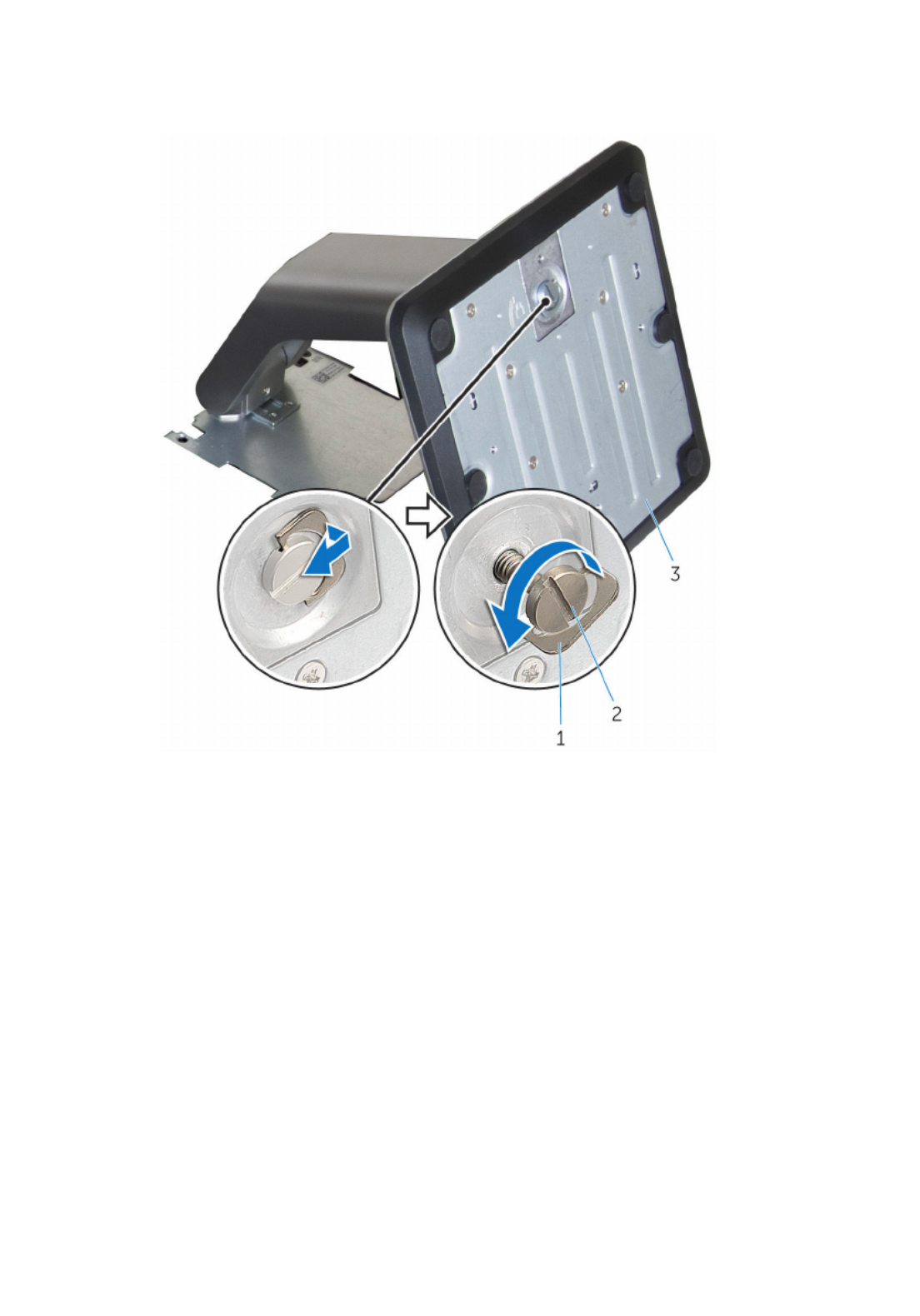
2 Using the screw handle, loosen the captive thumbscrew that secures the
stand base to the stand riser.
1 screw handle 2 captive thumbscrew
3 stand base
20

3 Slide the stand base off the stand riser.
1 stand riser 2 stand base
21

Replacing the stand
WARNING: Before working inside your computer, read the safety
information that shipped with your computer and follow the steps in
Before working inside your computer. After working inside your
computer, follow the instructions in After working inside your
computer. For more safety best practices, see the Regulatory
Compliance home page at www.dell.com/regulatory_compliance.
Easel stand
1 Insert the tabs on the stand bracket into the slots on the back cover.
2 Align the screw holes on the stand with the screw holes on the back
cover.
3 Replace the screws that secure the stand to the back cover.
4 Replace the stand cover.
Pedestal stand
1 Insert the tabs on the stand bracket into the slots on the back cover.
2 Align the screw holes on the stand with the screw holes on the back
cover.
3 Replace the screws that secure the stand bracket to the back cover.
4 Replace the stand cover.
Procedure to replace stand riser to stand base
1 Slide the stand base into the slot on the stand riser.
2 Tighten the captive thumbscrew and fold the screw handle on the stand
base.
22

3 Lift the back cover off the display-assembly base.
1 back cover
24

Replacing the back cover
WARNING: Before working inside your computer, read the safety
information that shipped with your computer and follow the steps in
Before working inside your computer. After working inside your
computer, follow the instructions in After working inside your
computer. For more safety best practices, see the Regulatory
Compliance home page at www.dell.com/regulatory_compliance.
Procedure
Align the tabs on the back cover with the slots on the display-assembly base
and snap the back cover into place.
NOTE:
NOTE:
NOTE:
NOTE: NOTE: Make sure that no cables are caught between the back cover and
the display-assembly base.
Post-requisites
Replace the .stand
25

Replacing the optical drive
WARNING: Before working inside your computer, read the safety
information that shipped with your computer and follow the steps in
Before working inside your computer. After working inside your
computer, follow the instructions in After working inside your
computer. For more safety best practices, see the Regulatory
Compliance home page at www.dell.com/regulatory_compliance.
Prerequisites
1 Remove the .stand
2 Remove the .back cover
Procedure
1 Disconnect the optical-drive cable from the optical drive.
2 Remove the screw that secures the optical-drive bracket to the display-
assembly base.
26

3 Lift the optical-drive bracket from the display-assembly base.
1 screw 2 optical drive
3 optical-drive cable
4 Carefully pull the optical-drive bezel and remove it from the optical drive.
5 Remove the screws that secure the optical-drive bracket to the optical
drive.
27

6 Remove the optical-drive bracket from the optical drive.
NOTE:
NOTE:
NOTE:
NOTE: NOTE: Note the orientation of the optical-drive bracket so that you
can replace it correctly.
1 optical-drive bezel 2 optical drive
3 optical-drive bracket 4 screws (2)
28

Removing the optical drive
WARNING: Before working inside your computer, read the safety
information that shipped with your computer and follow the steps in
Before working inside your computer. After working inside your
computer, follow the instructions in After working inside your
computer. For more safety best practices, see the Regulatory
Compliance home page at www.dell.com/regulatory_compliance.
Procedure
1 Align the screw holes on the optical-drive bracket with the screw holes
on the optical drive.
NOTE:
NOTE:
NOTE:
NOTE: NOTE: You must correctly align the optical-drive bracket to ensure
that the optical drive can be properly secured to the computer. For
correct orientation, see step 6 in " ".Removing the optical drive
2 Replace the screws that secure the optical-drive bracket to the optical
drive.
3 Carefully push the optical-drive bezel into the optical drive.
4 Place the optical-drive bracket on the display-assembly base.
5 Replace the screw that secures the optical-drive bracket to the display-
assembly base.
6 Connect the optical-drive cable to the optical drive.
Post-requisites
1 Replace the .back cover
2 Replace the .stand
29

Removing the hard drive
WARNING: Before working inside your computer, read the safety
information that shipped with your computer and follow the steps in
Before working inside your computer. After working inside your
computer, follow the instructions in After working inside your
computer. For more safety best practices, see the Regulatory
Compliance home page at www.dell.com/regulatory_compliance.
CAUTION: Hard drives are fragile. Exercise care when handling the
hard drive.
CAUTION: To avoid data loss, do not remove the hard drive while the
computer is in sleep or on state.
Prerequisites
1 Remove the .stand
2 Remove the .back cover
Procedure
1 Disconnect the hard-drive cable from the hard drive.
2 Remove the screw that secures the hard-drive assembly to the display-
assembly base.
3 Slide the hard-drive assembly until the securing tabs are released from
the slots on the display-assembly base.
30

4 Lift the hard-drive assembly off the display-assembly base.
1 display-assembly base 2 screw
3 hard-drive assembly 4 hard-drive cable
5 Remove the screws that secure the hard-drive bracket to the hard drive.
31
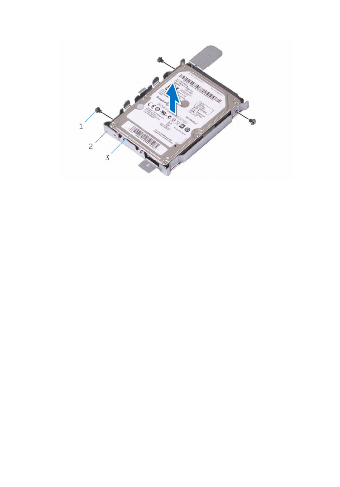
6 Remove the hard drive from the hard-drive bracket.
1 screws (3) 2 hard-drive bracket
3 hard drive
32

Removing the system-board
shield
WARNING: Before working inside your computer, read the safety
information that shipped with your computer and follow the steps in
Before working inside your computer. After working inside your
computer, follow the instructions in After working inside your
computer. For more safety best practices, see the Regulatory
Compliance home page at .www.dell.com/regulatory_compliance
Prerequisites
1 Remove the .stand
2 Remove the .back cover
Procedure
1 Remove the screws that secure the system-board shield to the display-
assembly base.
34
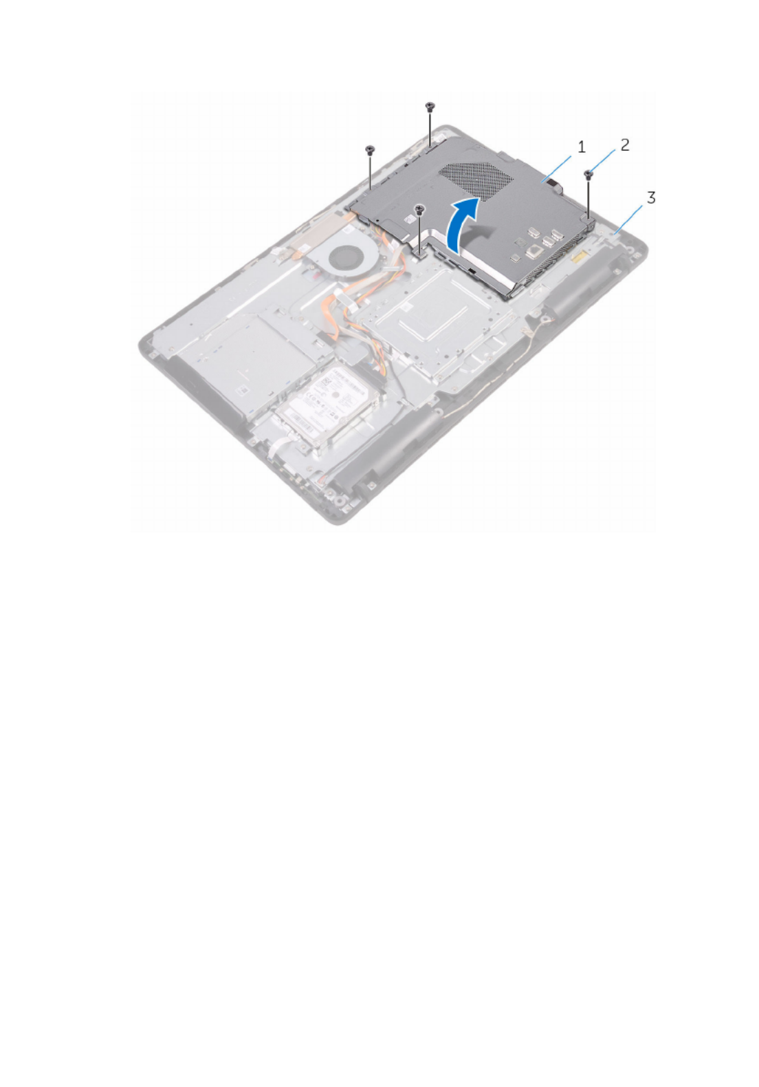
2 Lift the system-board shield off the display-assembly base.
1 system-board shield 2 screws (4)
3 display-assembly base
35

Replacing the system-board
shield
WARNING: Before working inside your computer, read the safety
information that shipped with your computer and follow the steps in
Before working inside your computer. After working inside your
computer, follow the instructions in After working inside your
computer. For more safety best practices, see the Regulatory
Compliance home page at .www.dell.com/regulatory_compliance
Procedure
1 Align the slots on the system-board shield with the ports on the system
board and place the system-board shield on the display-assembly base.
2 Align the screw holes on the system-board shield with the screw holes
on the display-assembly base.
3 Replace the screws that secure the system-board shield to the display-
assembly base.
Post-requisites
1 Replace the .back cover
2 Replace the .stand
36

Removing the memory module
WARNING: Before working inside your computer, read the safety
information that shipped with your computer and follow the steps in
Before working inside your computer. After working inside your
computer, follow the instructions in After working inside your
computer. For more safety best practices, see the Regulatory
Compliance home page at www.dell.com/regulatory_compliance.
Prerequisites
1 Remove the .stand
2 Remove the .back cover
3 Remove the .system-board shield
Procedure
1 Using your fingertips, spread apart the securing clips at each end of the
memory-module slot until the memory module pops up.
37

Replacing the memory module
WARNING: Before working inside your computer, read the safety
information that shipped with your computer and follow the steps in
Before working inside your computer. After working inside your
computer, follow the instructions in After working inside your
computer. For more safety best practices, see the Regulatory
Compliance home page at www.dell.com/regulatory_compliance.
Procedure
1 Align the notch on the memory module with the tab on the memory-
module slot.
39

Removing the wireless card
WARNING: Before working inside your computer, read the safety
information that shipped with your computer and follow the steps in
Before working inside your computer. After working inside your
computer, follow the instructions in After working inside your
computer. For more safety best practices, see the Regulatory
Compliance home page at www.dell.com/regulatory_compliance.
Prerequisites
1 Remove the .stand
2 Remove the .back cover
3 Remove the .system-board shield
Procedure
1 Remove the screw that secures the wireless-card bracket and the
wireless card to the system board.
2 Slide the wireless-card bracket off the wireless card.
3 Disconnect the antenna cables from the wireless card.
42

4 Slide the wireless card out of the wireless-card slot.
1 wireless-card bracket 2 screw
3 wireless-card slot 4 wireless card
5 antenna cables
43

Replacing the wireless card
WARNING: Before working inside your computer, read the safety
information that shipped with your computer and follow the steps in
Before working inside your computer. After working inside your
computer, follow the instructions in After working inside your
computer. For more safety best practices, see the Regulatory
Compliance home page at www.dell.com/regulatory_compliance.
Procedure
1 Align the notch on the wireless card with the tab on the wireless-card
slot.
2 Insert the wireless card into the wireless-card slot.
3 Connect the antenna cables to the wireless card.
The following table provides the antenna-cable color scheme for the
wireless card supported by your computer:
Connectors on the wireless card Antenna-cable color
Main (white triangle) White
Auxiliary (black triangle) Black
4 Press down the other end of the wireless card and align the screw hole
on the wireless-card bracket and wireless card with the screw hole on
the system board.
44

5 Replace the screw that secures the wireless-card bracket and the
wireless card to the system board.
1 tab 2 notch
3 wireless card 4 wireless-card slot
5 antenna cables 6 wireless-card bracket
7 screw
Post-requisites
1 Replace the .system-board shield
2 Replace the .back cover
45

Removing the control-buttons
board
WARNING: Before working inside your computer, read the safety
information that shipped with your computer and follow the steps in
Before working inside your computer. After working inside your
computer, follow the instructions in After working inside your
computer. For more safety best practices, see the Regulatory
Compliance home page at .www.dell.com/regulatory_compliance
Prerequisites
1 Remove the .stand
2 Remove the .back cover
Procedure
1 Using a plastic scribe, push the securing clips on the control-buttons
board slot.
NOTE:
NOTE:
NOTE:
NOTE: NOTE: Note the orientation of the control-buttons board so that
you can replace it correctly.
2 Press the securing clips and lift the control-buttons board off the display-
assembly base.
47

Replacing the control-buttons
board
WARNING: Before working inside your computer, read the safety
information that shipped with your computer and follow the steps in
Before working inside your computer. After working inside your
computer, follow the instructions in After working inside your
computer. For more safety best practices, see the Regulatory
Compliance home page at .www.dell.com/regulatory_compliance
Procedure
1 Slide the control-buttons board cable into the connector on the control-
buttons board and close the latch to secure the cable.
NOTE:
NOTE:
NOTE:
NOTE: NOTE: You must correctly align the control-buttons board to
ensure that it is properly secured to the display-assembly base. For
correct orientation, see step 1 in "Removing the control-buttons
board".
2 Slide the control-buttons board into the slot on the display-assembly
base until the securing clips lock in place.
Post-requisites
1 Replace the .back cover
2 Replace the .stand
49

Removing the microphone
WARNING: Before working inside your computer, read the safety
information that shipped with your computer and follow the steps in
Before working inside your computer. After working inside your
computer, follow the instructions in After working inside your
computer. For more safety best practices, see the Regulatory
Compliance home page at www.dell.com/regulatory_compliance.
Prerequisites
1 Remove the .stand
2 Remove the .back cover
Procedure
1 Lift the microphone module off the display-assembly base.
50

2 Disconnect the microphone cable from the microphone module.
1 microphone cable 2 display-assembly base
3 microphone module
51

Replacing the microphone
WARNING: Before working inside your computer, read the safety
information that shipped with your computer and follow the steps in
Before working inside your computer. After working inside your
computer, follow the instructions in After working inside your
computer. For more safety best practices, see the Regulatory
Compliance home page at www.dell.com/regulatory_compliance.
Procedure
1 Connect the microphone cable to the microphone module.
2 Slide the microphone module into the slot on the display-assembly base.
Post-requisites
1 Replace the .back cover
2 Replace the .stand
52
Removing the camera
WARNING: Before working inside your computer, read the safety
information that shipped with your computer and follow the steps in
Before working inside your computer. After working inside your
computer, follow the instructions in After working inside your
computer. For more safety best practices, see the Regulatory
Compliance home page at www.dell.com/regulatory_compliance.
Prerequisites
NOTE:
NOTE:
NOTE:
NOTE: NOTE: This chapter is applicable only for systems with a touch screen
display. For systems with a non-touch screen display, the microphones
will be integrated on the camera assembly.
1 Remove the .stand
2 Remove the .back cover
Procedure
1 Disconnect the camera cable and antenna cable from the system board.
53

2 Note the routing of the camera cable and antenna cable and remove it
from the routing guides.
1 camera cable 2 routing guides
3 display-assembly base 4 camera frame
5 antenna cable
54

3 Press the securing clip to release the camera frame from the tab on the
display-assembly base and lift it off.
1 securing clip 2 display-assembly base
3 camera frame
4 Turn the camera over.
55

5 Remove the camera cable from the tab on the back of the camera frame.
1 camera cable 2 camera frame
6 Peel off the camera from the camera frame and lift up the camera from
the frame.
1 camera frame 2 camera
56

Replacing the camera
WARNING: Before working inside your computer, read the safety
information that shipped with your computer and follow the steps in
Before working inside your computer. After working inside your
computer, follow the instructions in After working inside your
computer. For more safety best practices, see the Regulatory
Compliance home page at www.dell.com/regulatory_compliance.
Procedure
1 Place the camera on the camera frame and secure the camera.
2 Connect the camera cable to the camera module.
3 Press the camera frame down into the slot on the display-assembly base
until it snaps into place.
4 Route the camera cable and antenna cable through the routing guides on
the display-assembly base.
5 Connect the camera cable and antenna cable to the system board.
Post-requisites
1 Replace the .back cover
2 Replace the .stand
57
Produktspezifikationen
| Marke: | Dell |
| Kategorie: | Desktop |
| Modell: | Inspiron 22 3264 |
| Touchscreen: | Ja |
| Bildschirmdiagonale: | 21.5 " |
| Eingebautes Mikrofon: | Ja |
| Eingebaute Lautsprecher: | Ja |
| Integrierte Kamera: | Ja |
| Installiertes Betriebssystem: | Windows 10 Home |
| Prozessorhersteller: | Intel |
| Anzahl Prozessorkerne: | 2 |
| WLAN: | Ja |
| Bluetooth: | Ja |
| AC-Netzadapter: | Ja |
| Produkttyp: | All-in-One-PC |
| Produktfarbe: | Black, White |
| Garantiekarte: | Ja |
| RMS-Leistung: | 3 W |
| Anzahl USB 2.0 Anschlüsse: | 2 |
| Gleichstrom-Anschluss (DC): | Ja |
| Betriebstemperatur: | 0 - 35 °C |
| Relative Luftfeuchtigkeit in Betrieb: | 10 - 90 % |
| Netzteil Ausgangsspannung: | 19.5 V |
| Netzteil Eingansgsspannung: | 100 - 240 V |
| Anzahl Ethernet-LAN-Anschlüsse (RJ-45): | 1 |
| Betriebsanleitung: | Ja |
| HD-Typ: | Full HD |
| Bildschirmform: | Flach |
| Natives Seitenverhältnis: | 16:9 |
| Anzahl HDMI-Anschlüsse: | 1 |
| Ethernet LAN Datentransferraten: | 10, 100 Mbit/s |
| Temperaturbereich bei Lagerung: | -40 - 65 °C |
| Luftfeuchtigkeit bei Lagerung: | 0 - 95 % |
| Audio-System: | Waves MaxxAudio Pro |
| Gewicht (ohne Ständer): | 5370 g |
| Tiefe (ohne Standfuß): | 33.1 mm |
| Gerätebreite (inkl. Fuß): | 526.2 mm |
| Gerätetiefe (inkl. Fuß): | 55.85 mm |
| Gerätehöhe (inkl. Fuß): | 349.55 mm |
| Gewicht (mit Ständer): | 5350 g |
| Netzteilfrequenz: | 50/60 Hz |
| Prozessor-Taktfrequenz: | 2.3 GHz |
| Prozessorfamilie: | Intel® Pentium® |
| Prozessor: | 4415U |
| Kompatible Speicherkarten: | MMC, SD, SDHC, SDXC |
| Anzahl der installierten Speicherlaufwerke: | 1 |
| Speicherkapazität: | 8 GB |
| USB 3.2 Gen 1 (3.1 Gen 1) Anzahl der Anschlüsse vom Typ A: | 2 |
| Prozessor-Cache: | 2 MB |
| Konfliktloser-Prozessor: | Ja |
| Prozessor Cache Typ: | Smart Cache |
| Prozessor Codename: | Kaby Lake |
| Prozessor Lithografie: | 14 nm |
| Prozessorbetriebsmodi: | 64-Bit |
| Prozessor-Paketgröße: | 42 x 24 mm |
| Prozessor-Threads: | 4 |
| Systembus-Rate: | 4 GT/s |
| Thermal Design Power (TDP): | 15 W |
| ARK Prozessorerkennung: | 96508 |
| Interner Speichertyp: | DDR4-SDRAM |
| Integrierter Kartenleser: | Ja |
| Intel® Turbo-Boost-Technologie: | Nein |
| Eingebettete Optionen verfügbar: | Nein |
| Intel® 64: | Ja |
| Intel® Virtualization Technologie (VT-X): | Ja |
| Tastatur enthalten: | Ja |
| Audio-Chip: | Realtek ALC3661 |
| Arbeitsspeicher Typ: | SO-DIMM |
| RAM-Speicher maximal: | 16 GB |
| Treiber enthalten: | Ja |
| Abnehmbares Display: | Nein |
| Maus enthalten: | Ja |
| LED-Hintergrundbeleuchtung: | Ja |
| HDD Kapazität: | 1000 GB |
| HDD Geschwindigkeit: | 5400 RPM |
| Speichermedien: | HDD |
| Gesamtspeicherkapazität: | 1000 GB |
| Kombinierter Kopfhörer-/Mikrofon-Anschluss: | Ja |
| Höhe bei Betrieb: | -15.2 - 3048 m |
| Intel® Hyper-Threading-Technik (Intel® HT Technology): | Ja |
| Intel® Smart-Response-Technologie: | Ja |
| Verbesserte Intel SpeedStep Technologie: | Ja |
| PCI-Express-Slots-Version: | 2.0 |
| Tjunction: | 100 °C |
| PCI Express Konfigurationen: | 1x2+2x1, 1x4, 2x2, 4x1 |
| Maximale Anzahl der PCI-Express-Lanes: | 10 |
| Maximaler interner Speicher, vom Prozessor unterstützt: | 32 GB |
| Speichertypen, vom Prozessor unterstützt: | DDR3L-SDRAM, DDR4-SDRAM, LPDDR3-SDRAM |
| Speichertaktraten, vom Prozessor unterstützt: | 1600,1866,2133 MHz |
| Durch den Prozessor (max) unterstützte Speicherbandbreite: | 34.1 GB/s |
| On-Board Grafikadaptermodell: | Intel® HD Graphics 610 |
| Eingebaute Grafikadapter: | Ja |
| Dediziertes Grafikadaptermodell: | Nicht verfügbar |
| Separater Grafikadapter: | Nein |
| On-Board Grafikadapter Basisfrequenz: | 300 MHz |
| Maximale dynamische Frequenz der On-Board Grafikadapter: | 950 MHz |
| On-Board Grafikadapter Geräte-ID: | 0x5906 |
| Maximaler integrierter Grafik-Adapterspeicher: | 32 GB |
| Anzahl an unterstützen Displays (On-Board-Grafik): | 3 |
| On-Board Grafikadapter DirectX Version: | 12.0 |
| On-Board Grafikadapter OpenGL Version: | 4.4 |
| Speichertaktfrequenz: | 2400 MHz |
| Speicherkartensteckplätze: | 2 |
| Anzahl der installierten HDDs: | 1 |
| Optisches Laufwerk - Typ: | DVD Super Multi |
| Betriebssystemsarchitektur: | 64-Bit |
| Netzkabel enthalten: | Ja |
| Unterstützte Befehlssätze: | SSE4.1, SSE4.2 |
| Intel® Quick-Sync-Video-Technik: | Ja |
| Intel® Clear Video HD Technology für (Intel® CVT HD): | Ja |
| Intel® AES New Instructions (Intel® AES-NI): | Ja |
| Execute Disable Bit: | Ja |
| Leerlauf Zustände: | Ja |
| Thermal-Überwachungstechnologien: | Ja |
| Intel® Trusted-Execution-Technik: | Nein |
| CPU Konfiguration (max): | 1 |
| Intel® VT-x mit Extended Page Tables (EPT): | Ja |
| Intel® TSX-NI: | Nein |
| Intel® Sicherer Schlüssel: | Ja |
| Intel Stable Image Platform Program (SIPP): | Nein |
| Intel® OS Guard: | Ja |
| Intel® Virtualisierungstechnik für direkte I/O (VT-d): | Ja |
| Intel® Clear Video Technologie: | Ja |
| Intel® Software Guard Extensions (Intel® SGX): | Ja |
| Pixel Abstand: | 0.2479 x 0.2479 mm |
| Bus Typ: | OPI |
| Speicherkanäle, vom Prozessor unterstützt: | Dual |
| ECC vom Prozessor unterstützt: | Nein |
| HDD Schnittstelle: | SATA III |
| Intel® My-WiFi-Technik (Intel® MWT): | Ja |
| Intel® Flex Memory Access: | Ja |
| Megapixel insgesamt: | 0.92 MP |
| Autonomie-Modus: | Nein |
| Memory Formfaktor: | DIMM/SO-DIMM |
| TDP-down konfigurierbar: | 10 W |
| Audioausgang: | Ja |
| Kamera-Auflösung: | 1280 x 720 Pixel |
| Optische Festplatte interface: | SATA |
| Display-Auflösung: | 1920 x 1080 Pixel |
| Ethernet/LAN: | Ja |
| Unterstützte Positionierung: | Horizontal |
Brauchst du Hilfe?
Wenn Sie Hilfe mit Dell Inspiron 22 3264 benötigen, stellen Sie unten eine Frage und andere Benutzer werden Ihnen antworten
Bedienungsanleitung Desktop Dell

21 September 2024
17 September 2024
15 September 2024
5 September 2024
3 September 2024
31 August 2024
28 August 2024
28 August 2024
28 August 2024
28 August 2024
Bedienungsanleitung Desktop
- Desktop Samsung
- Desktop Acer
- Desktop Apple
- Desktop Asus
- Desktop BenQ
- Desktop Gigabyte
- Desktop HP
- Desktop Medion
- Desktop Microsoft
- Desktop Sharkoon
- Desktop Sony
- Desktop LG
- Desktop Sharp
- Desktop WOOOD
- Desktop Haier
- Desktop TrekStor
- Desktop Optoma
- Desktop PEAQ
- Desktop Toshiba
- Desktop Mio
- Desktop ViewSonic
- Desktop LC-Power
- Desktop Lenovo
- Desktop MSI
- Desktop JYSK
- Desktop Tripp Lite
- Desktop Razer
- Desktop ELO
- Desktop Targa
- Desktop Xoro
- Desktop Vtech
- Desktop Parisot
- Desktop Wehkamp
- Desktop Supermicro
- Desktop Faytech
- Desktop InFocus
- Desktop NEC
- Desktop Seagate
- Desktop Fujitsu
- Desktop Maxdata
- Desktop Packard Bell
- Desktop Kogan
- Desktop ZTE
- Desktop Atari
- Desktop Kramer
- Desktop Asrock
- Desktop ECS
- Desktop Promethean
- Desktop Vorago
- Desktop Emachines
- Desktop Ibm
- Desktop MP
- Desktop ONYX
- Desktop Alienware
- Desktop Zotac
- Desktop Intel
- Desktop Moxa
- Desktop VXL
- Desktop Planar
- Desktop Shuttle
- Desktop Altra
- Desktop Axis
- Desktop Advantech
- Desktop Elitegroup
- Desktop BDI
- Desktop Bestar
- Desktop Pelco
- Desktop Foxconn
- Desktop System76
- Desktop NComputing
- Desktop Cybernet
- Desktop Aopen
- Desktop Smart Things
- Desktop Zoostorm
- Desktop Dell Wyse
- Desktop MvixUSA
- Desktop AIS
- Desktop Wyse
Neueste Bedienungsanleitung für -Kategorien-

30 November 2024

15 Oktober 2024

14 Oktober 2024
12 Oktober 2024
11 Oktober 2024

9 Oktober 2024

9 Oktober 2024

7 Oktober 2024
4 Oktober 2024
4 Oktober 2024