Asus RS920-E7/RS8 Bedienungsanleitung
Lesen Sie kostenlos die 📖 deutsche Bedienungsanleitung für Asus RS920-E7/RS8 (200 Seiten) in der Kategorie Server. Dieser Bedienungsanleitung war für 20 Personen hilfreich und wurde von 2 Benutzern mit durchschnittlich 4.5 Sternen bewertet
Seite 1/200

2U Rackmount
Server
RS920-E7/RS8
RS926-E7/RS8
User Guide

ii
Copyright © 2012 ASUSTeK COMPUTER INC. All Rights Reserved.
No part of this manual, including the products and software described in it, may be reproduced, transmitted,
transcribed, stored in a retrieval system, or translated into any language in any form or by any means,
except documentation kept by the purchaser for backup purposes, without the express written permission
of ASUSTeK COMPUTER INC. (“ASUS”).
ASUS provides this manual “as is” without warranty of any kind, either express or implied, including but not
limited to the implied warranties or conditions of merchantability or tness for a particular purpose. In no
event shall ASUS, its directors, ofcers, employees, or agents be liable for any indirect, special, incidental,
or consequential damages (including damages for loss of prots, loss of business, loss of use or data,
interruption of business and the like), even if ASUS has been advised of the possibility of such damages
arising from any defect or error in this manual or product.
Specications and information contained in this manual ae furnished for informational use only, and are
subject to change at any time without notice, and should not be construed as a commitment by ASUS.
ASUS assumes no responsibility or liability for any errors or inaccuracies that may appear in this manual,
including the products and software described in it.
Product warranty or service will not be extended if: (1) the product is repaired, modied or altered, unless
such repair, modication of alteration is authorized in writing by ASUS; or (2) the serial number of the
product is defaced or missing.
Products and corporate names appearing in this manual may or may not be registered trademarks or
copyrights of their respective companies, and are used only for identication or explanation and to the
owners’ benet, without intent to infringe.
E7284
First Edition
March 2012

iii
Contents
Notices ........................................................................................................ vii
Safety information ...................................................................................... ix
About this guide .......................................................................................... x
Chapter 1: Product introduction
1.1 System package contents ........................................................... 1-2
1.2 Serial number label ......................................................................1-3
1.3 Systemspecications .................................................................1-4
1.4 Front panel features .....................................................................1-6
1.5 Rear panel features ......................................................................1-6
1.6 Internal features ...........................................................................1-7
1.7 LED information ...........................................................................1-8
1.7.1 Front panel LEDs ............................................................1-8
1.7.2 LAN (RJ-45) LEDs ..........................................................1-9
1.7.3 HDD status LED ............................................................1-10
Chapter 2: Hardware setup
2.1 Chassis cover ............................................................................... 2-2
2.2 Central Processing Unit (CPU) ...................................................2-3
2.2.1 Installing the CPU ...........................................................2-3
2.2.2 Installing the CPU heatsink and airduct ..........................2-8
2.3 System memory ...........................................................................2-9
2.3.1 Overview .........................................................................2-9
2.3.2 Memory Congurations .................................................2-10
2.4 Hard disk drives .........................................................................2-13
2.5 Expansion slot ............................................................................2-15
2.5.1 Installing an expansion card to the riser card bracket ...2-15
2.5.2 Conguring an expansion card .....................................2-17
2.6 Cable connections .....................................................................2-18
2.7 SATAII/SAS backplane cabling .................................................2-19
2.8 Removable/optional components .............................................2-20
2.8.1 System fans ..................................................................2-20
2.8.2 Redundant power supply units ......................................2-21
2.8.3 Installing ASUS PIKE RAID card (optional) ..................2-23

v
Contents
5.4.6 PCI Subsystem Settings ............................................... 5-22
5.4.7 Onboard LAN Conguration ..........................................5-25
5.4.8 USB Conguration ........................................................5-27
5.4.9 Trusted Computing ........................................................5-28
5.4.10 ACPI Settings ................................................................5-29
5.4.11 WHEA Conguration .....................................................5-30
5.4.12 APM setting ...................................................................5-30
5.4.13 Serial Port Console Redirection ....................................5-31
5.4.14 ME Subsystem ..............................................................5-34
5.4.15 Onboard Device Conguration ......................................5-34
5.4.16 Runtime Error Logging ..................................................5-35
5.5 Server Mgmt menu .....................................................................5-36
5.5.1 System Event Log .........................................................5-37
5.5.2 BMC network conguration ...........................................5-38
5.6 Event Logs menu .......................................................................5-39
5.6.1 Change Smbios Event Log Settings .............................5-39
5.7 Boot menu ..................................................................................5-41
5.8 Monitor menu .............................................................................5-43
5.9 Security menu ............................................................................5-44
5.10 Tool menu ...................................................................................5-46
5.11 Exit menu ....................................................................................5-46
Chapter6: RAIDconguration
6.1 Setting up RAID ............................................................................ 6-2
6.1.1 RAID denitions ..............................................................6-2
6.1.2 Installing hard disk drives ................................................6-3
6.1.3 Setting the RAID item in BIOS ........................................6-3
6.1.4 RAID conguration utilities ..............................................6-3
6.2 LSISoftwareRAIDCongurationUtility ...................................6-4
6.2.1 Creating a RAID set ........................................................6-5
6.2.2 Adding or viewing a RAID conguration ........................6-11
6.2.3 Initializing the virtual drives ...........................................6-12
6.2.4 Rebuilding failed drives .................................................6-16
6.2.5 Checking the drives for data consistency .....................6-18
6.2.6 Deleting a RAID conguration .......................................6-21

vi
Contents
6.2.7 Selecting the boot drive from a RAID set ...................... 6-22
6.2.8 Enabling WriteCache ....................................................6-23
6.3 Intel® Rapid Storage Technology enterprise SCU/SATA
Option ROM Utility .....................................................................6-24
6.3.1 Creating a RAID set ......................................................6-26
6.3.2 Creating a Recovery set ...............................................6-27
6.3.3 Deleting a RAID set ......................................................6-29
6.3.4 Resetting disks to Non-RAID ........................................6-30
6.3.5 Exiting the Intel® Rapid Storage Technology utility ........ 16-3
6.3.6 Rebuilding the RAID .....................................................6-31
6.3.7 Setting the Boot array in the BIOS Setup Utility ............6-33
6.4 Intel® Rapid Storage Technology enterprise Utility (Windows) 6-34
6.4.1 Creating a RAID set ......................................................6-35
6.4.2 Change Volume Type ....................................................6-37
6.4.3 Delete volume ...............................................................6-38
6.4.4 Preferences ...................................................................6-39
Chapter 7: Driver installation
7.1 RAID driver installation ............................................................... 7-2
7.1.1 Creating a RAID driver disk ............................................7-2
7.1.2 Installing the RAID controller driver ................................7-4
7.2 Intel® chipset device software installation ............................... 7-15
7.3 Intel@ Network Connections Software installation.................. 7-17
7.4 VGA driver installation............................................................... 7-20
7.5 Intel® C600 Series Chipset SATA RAID Drivers ....................... 7-23
7.6 Microsoft .NET Framework 3.5 SP1 ..........................................7-24
7.7 Intel® Rapid Storage Technology enterprise 3.0 installation . 7-25
7.8 Intel® I350 Gigabit Adapters Driver installation ....................... 7-28
7.9 Management applications and utilities installation ................7-32
7.9.1 Running the support DVD .............................................7-32
7.9.2 Drivers menu .................................................................7-32
7.9.3 Utilities menu ................................................................7-33
7.9.4 Make disk menu ............................................................7-33
7.9.5 Contact information .......................................................7-33
ASUS contact information .......................................................................A-1
vii
Notices
Federal Communications Commission Statement
This device complies with Part 15 of the FCC Rules. Operation is subject to the
following two conditions:
• This device may not cause harmful interference, and
• This device must accept any interference received including interference that
may cause undesired operation.
This equipment has been tested and found to comply with the limits for a Class
B digital device, pursuant to Part 15 of the FCC Rules. These limits are designed
to provide reasonable protection against harmful interference in a residential
installation. This equipment generates, uses and can radiate radio frequency
energy and, if not installed and used in accordance with manufacturer’s instructions,
may cause harmful interference to radio communications. However, there is no
guarantee that interference will not occur in a particular installation. If this equipment
does cause harmful interference to radio or television reception, which can be
determined by turning the equipment off and on, the user is encouraged to try to
correct the interference by one or more of the following measures:
• Reorient or relocate the receiving antenna.
• Increase the separation between the equipment and receiver.
• Connect the equipment to an outlet on a circuit different from that to which the
receiver is connected.
• Consult the dealer or an experienced radio/TV technician for help.
Canadian Department of Communications Statement
This digital apparatus does not exceed the Class B limits for radio noise emissions
from digital apparatus set out in the Radio Interference Regulations of the
Canadian Department of Communications.
This Class B digital apparatus complies with Canadian ICES-003.
WARNING! The use of shielded cables for connection of the monitor to the
graphics card is required to assure compliance with FCC regulations. Changes
or modications to this unit not expressly approved by the party responsible for
compliance could void the user’s authority to operate this equipment.

xii

1-
This chapter describes the general
features of the chassis kit. It includes
sections on front panel and rear panel
specications.
Chapter 1
Product introduction

Chapter 1: Product introduction1-2
* ThesystemdoesnotincludeaUSBoppydrive.YoumayhavetouseaUSBoppydrive
when creating a SATA RAID driver disk. Refer to Chapter 7 for details.
*ASUS System Web-based Management
If any of the above items is damaged or missing, contact your retailer.
1.1 System package contents
Check your system package for the following items.
Model Name RS920-E7/RS8 RS926-E7/RS8
Chassis ASUS Rackmount ChassisR21B 2U
Motherboard ASUS Z9PX-Q32 Series Server Board
Component 1 x 1620W 80PLUS Platinum Redundant Power Supply
1 x SATA Backplane with 8 x SATA Cables
3 x PCIe riser card
1 x Front I/O Shield (FPB-AR14)
1 x Power Supply Power Distribution Board
5 x System Fans (80mm)
Accessories 1 x User’s Guide
1 x RS92x-E7/RS8 Series Support DVD
1 x Bag of Screws
1 x Friction Rail Kit
Optional Items CPU Heatsink
Anti-virus CD

ASUS RS920-E7/RS8; RS926-E7/RS8 1-3
1.2 Serial number label
Before requesting support from the ASUS Technical Support team, you must
take note of the product’s serial number containing 14 characters such as
xxS0xxxxxxxxxx. See the gure below.
With the correct serial number of the product, ASUS Technical Support team
members can then offer a quicker and satisfying solution to your problems.
xxS0xxxxxxxxxx
RS92x -E7/RS8

Chapter 1: Product introduction1-4
1.3 Systemspecications
The ASUS RS920-E7/RS8 and RS926-E7/RS8 are servers featuring the ASUS
Z9PX-Q32 Series server board.The server supports the
Intel® Xeon® E5-4600 processor family, plus other latest technologies through the
chipsets onboard.
(continued on the next page)
Model Name RS926-E7/RS8 RS920-E7/RS8
Processor Support 4 x LGA 2011 socket
Intel® Xeon® Processor E5-4600 Product Family (up
to 130W)
Intel® QuickPath Interconnect (QPI) 6.4/7.2/8.0 GT/s
Core Logic Intel® C602-A chipset
Memory Total Slots 32 (4-channel per CPU, 2 DIMM per channel)
Capacity Maximum up to 1024GB (RDIMM)
Maximum up to 256GB (UDIMM)
Memory Type DDR3 800/1066/1333/1600 RDIMM
DDR3 1066/1333 ECC UDIMM/Non-ECC UDIMM
DDR3 1066/1333 LR-DIMM
Memory Size 1GB, 2GB, 4GB, 8GB, 16GB, 32GB* (RDIMM)
1GB, 2GB, 4GB, 8GB* (UDIMM)
8GB, 16GB, 32GB* (LRDIMM)
Expansion
Slots
Total PCI/
PCI-X/PCI-E
Slots
6 (PCI riser card required)
Slot type Full-length
4 x PCI-E x16
(2 x Gen3 x16 Link or 4 x Gen3 p16-x8 Link)
Half-length/Low-prole
2 x PCI-E p16-x8 (Gen3 x8 Link)
Additional
Slot PIKE slot (PCI-E Gen3 p16-x8 Link)
Storage SATA
Controller
Intel® C602-A Chipset
- 2 x SATA 6 Gb/s(black), 4 x SATA 3 Gb/s(black)
AHCI port
- 4 x SATA 3 Gb/s (blue) SCU ports
Intel® Rapid Storage Technology (for Windows only)
Supports RAID 0, RAID 1, RAID 10, and RAID 5
LSI® Mega RAID (for Windows/Linux)
Supports software RAID 0, 1, & 10
SAS
Controller
Optional:
ASUS PIKE 2008 8-port SAS2 6G RAID card
ASUS PIKE 2008/IMR 8-port SAS2 6G RAID card
ASUS PIKE 2108 8-port SAS2 6G H/W RAID card
HDD Bays 8 x Hot-swappable 3.5” HDD Bays

ASUS RS920-E7/RS8; RS926-E7/RS8 1-5
*Specicationsaresubjecttochangewithoutnotice.
Model Name RS926-E7/RS8 RS920-E7/RS8
Networking LAN Quad Port Intel Ethernet Controller i350 + 1
Management port
Inniband Single port Mellanox
ConnectX-3 FDR
InniteBand with QSFP
Interface
N/A
Graphic VGA Aspeed AST2300 16MB
Auxiliary Storage Device Bay 1 x Slim-type Optical Device Bay
Onboard I/O 1 x Internal Serial Port
5 x RJ-45 ports (1 port for remote management)
6 x USB 2.0 ports (2 x Front panel; 4 x Rear panel)
2 x USB 3.0 ports (Rear)
1 x Internal A Type USB port
1 x VGA port
1 x PS/2 keyboard/mouse port
1 x QSFP port N/A
OS Support Windows® Server 2008 R2
Windows Server 2008 R2 Enterprise
Windows Server 2008 Enterprise 32/64-bit
RedHat Enterprise Linux AS5.6/6.0 32/64-bit
SuSE Linux Enterprise Server 11.2 32/64-bit
CentOS 5.6 32/64-bit
VMWare ESX4.1/ESXi4.1
Anti-virus Software Optional Anti-Virus CD pack
Management
Solution
Software ASWM Enterprise
Out of Band
Management
ASMB6-iKVM for KVM-over-IP onboard
Dimension (L x W x H) 75 cm x 44.4 cm x 8.8 cm (2U)
Net Weight (kg) 20 kg
Power Supply 1 + 1 Redundant 1620W 80PLUS Platinum Power
Supply
Power Rating Input: 100—140/180—240 Vac, 12—10A/10.5A—A,
50—60Hz Class1
Environment Operating Temperature: 10 C ~ 35° °C
Non-operating Temperature: -40 C ~ 70° °C
Non-operating Humidity: 20% ~ 90% (non-
condensing)

Chapter 1: Product introduction1-6
1.4 Front panel features
The barebone server displays a simple yet stylish front panel with easily accessible
features. The power and reset buttons, LED indicators, optical drive, and two USB
ports are located on the front panel.
• The rear I/O ports do not appear on the rear panel if motherboard is not
present.
• *The port is for ASUS ASMB6-iKVM controller card only.
1.5 Rear panel features
The rear panel includes the expansion slots, system power socket, and rear fans.
The middle part includes the I/O shield with openings for the rear panel connectors
on the motherboard.
Refer to section for the LED descriptions.1.7.1 Front panel LEDs
ODD dummy cover USB ports
P o w e r
button
Power LED
LAN2 LED
HDD Access LED
LAN1 LED
Message LED
Location switch
Reset button
Location LED
HDD 1 HDD 5 HDD 2 HDD 6 HDD 3 HDD 7 HDD 4 HDD 8
Redundant
power supply
Power cord
connector
LAN port 1
2 Full-length /
Full-height
Expansion slot
2 Full-length /
Full-height
Expansion slot
Power cord
connector
Redundant
power supply
LAN port 2
LAN port 3
LAN port 4
InfiniBand
port
LAN port 5*
USB 3.0 ports VGA port
USB 2.0 ports
2 Half-length /
Low-prole
Expansion slot
ASUS RS920-E7/RS8; RS926-E7/RS8 1-7
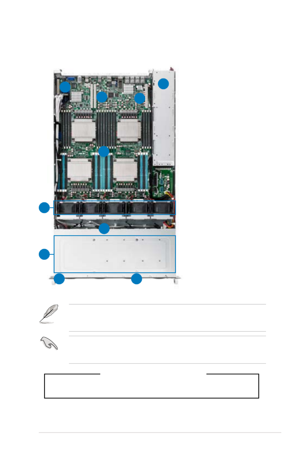
1.6 Internal features
The barebone server includes the basic components as shown.
The barebone server does not include a oppy disk drive. Connect a USB oppy
disk drive to any of the USB ports on the front or rear panel if you need to use a
oppy disk.
*WARNING
HAZARDOUS MOVING PARTS
KEEP FINGERS AND OTHER BODY PARTS AWAY
1. Redundant Power
supply and power fan
(hidden)
2. ASUS Z9PX-Q32
Server Board
3. System fans
4. SATA/SAS backplane
(hidden)
5. Hot-swap HDD tray
1–8 (SAS and SATA)
6. Slim-type optical drive
bay
7. Front I/O board
(hidden)
8. PCI-E Expansion
Boards (hidden)
A protection lm is pre-attached to the front cover before shipping. Please
remove the protection lm before turning on the system for proper heat
dissipation.
3
1
2
4
5
6 7
8
8
8

Chapter 1: Product introduction1-8
1.7 LED information
1.7.1 Front panel LEDs
LED Icon Display
status Description
Power LED ON System power ON
Location
LED
OFF Normal status
ON Location switch is pressed (Press the location switch again to
turn off)
Message
LED
OFF System is normal; no incoming event
ON
1. Without ASMB6-iKVM installed: CPU over-heated
2. With ASMB6-iKVM installed: a hardware monitor event is
indicated
LAN LEDs
OFF No LAN connection
Blinking LAN is transmitting or receiving data
ON LAN connection is present
HDD
Access
LED
OFF No activity
Blinking Read/write data into the HDD
Message LED
LAN2 LED
HDD Access LED
LAN1 LED
Power LED
Location LED

Chapter 1: Product introduction1-10
1.7.3 HDD status LED
SATAII/SAS HDD LED Description
HDD Activity LED (Green)
OFF HDD not present
ON HDD present, no activity
Blinking 1. Read/write data from/into the SATAII/SAS HDD
2. Locating (blinking with the HDD status LED)
HDD Status LED (Red)
OFF HDD not present
ON HDD has failed and should be swapped immediately
Blinking 1. RAID rebuilding
2. Locating (blinking with the HDD activity LED)
HDD Activity LED (Green)
HDD Status LED (Red)

2-
This chapter lists the hardware setup
procedures that you have to perform
when installing or removing system
components.
Chapter 2
Hardware setup

Chapter 2: Hardware setup2-2
2.1 Chassis cover
Removing the rear cover
1. Locate and remove the side screws.
3. Firmly hold the cover and slide it
toward the rear panel for about half
an inch until it is disengaged from
the chassis.
4. Lift the cover from the chassis.
5. To recover the rear cover, reverse
step 1 to 4.
A protection lm is pre-attached
to the system cover before
shipping. Please remove the
protection lm before turning
on the system for proper heat
dissipation.
2. Loosen the two thumbscrews on the rear panel.
Thumbscrews

2-3ASUS RS920-E7/RS8; RS926-E7/RS8
2.2.1 Installing the CPU
To install a CPU:
1. Locate the CPU socket on the motherboard.
2.2 Central Processing Unit (CPU)
The motherboard comes with a surface mount LGA2011 socket designed for the
Intel® Xeon E5-4600 family processor.
• Upon purchase of the motherboard, ensure that the PnP cap is on
the socket and the socket contacts are not bent. Contact your retailer
immediately if the PnP cap is missing, or if you see any damage to the PnP
cap/socket contacts/motherboard components. ASUS will shoulder the cost
of repair only if the damage is shipment/transit-related.
• Keep the cap after installing the motherboard. ASUS will process Return
Merchandise Authorization (RMA) requests only if the motherboard comes
with the cap on the LGA2011 socket.
• The product warranty does not cover damage to the socket contacts
resulting from incorrect CPU installation/removal, or misplacement/loss/
incorrect removal of the PnP cap.
Before installing the CPU, ensure that the socket box is facing towards you and
the load lever is on your left.

Chapter 2: Hardware setup2-4
2. Press the left load lever with your
thumb (A), then move it to the left
(B) until it is released from the
retention tab.
To prevent damage to the socket
pins, do not remove the PnP cap
unless you are installing a CPU.
B
A
E
D
C
4. Press the right load lever with your
thumb (C), then move it to the right
(D) until it is released from the
retention tab. Lift the load lever in
the direction of the arrow (E).
3. Slightly lift the load lever in the
direction of the arrow.
Load lever
2-5ASUS RS920-E7/RS8; RS926-E7/RS8
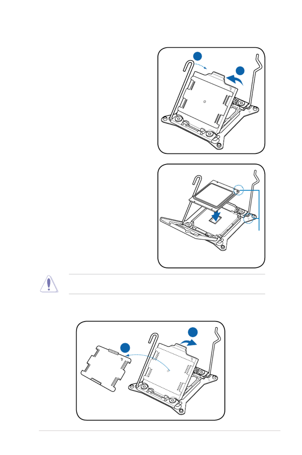
I
H
7. Remove the PnP cap (H) from the CPU socket and close the load plate (I).
G
F
5. Push the left load lever (F) to lift the
load plate (G).
The CPU ts in only one correct orientation. DO NOT force the CPU into the
socket to prevent bending the connectors on the socket and damaging the CPU!
Triangle
mark
6. Position the CPU over the socket,
ensuring that the triangle mark is on
the top-right corner of the socket.

2-7ASUS RS920-E7/RS8; RS926-E7/RS8
The Thermal Interface Material is toxic and inedible. DO NOT eat it. If it
gets into your eyes or touches your skin, wash it off immediately, and seek
professional medical help.
Some heatsinks come with pre-
applied thermal paste. If so, skip
this step.
11. Apply some Thermal Interface
Material to the exposed area of
the CPU that the heatsink will be
in contact with, ensuring that it is
spread in an even thin layer.
Chapter 2: Hardware setup2-8
2. Twist each of the four screws with
a Philips (cross) screwdriver just
enough to attach the heatsink to
the motherboard. When the four
screws are attached, tighten them
one by one to completely secure the
heatsink.
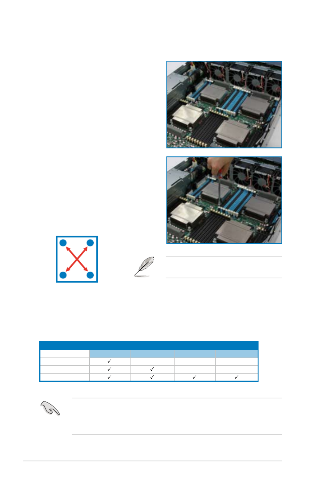
2.2.2 Installing the CPU heatsink and airduct
Tighten the four heatsink screws in a
diagonal sequence.
AB
B A
To install the CPU heatsink:
1. Place the heatsink on top of the
installed CPU, ensuring that the four
fasteners match the holes on the
motherboard.
Apply some Thermal Interface Material to the exposed area of the CPU that the
heatsink will be in contact with, ensuring that it is spread in an even thin layer.
Some heatsinks come with pre-applied Thermal Interface Material. If so, skip
this step.
CPU Installation Sequence:
CPU1 Conguration
CPU1 Socket CPU3 SocketCPU2 Socket CPU4 Socket
One Processor
Dual Processors
Quad Processors

2-9ASUS RS920-E7/RS8; RS926-E7/RS8
2.3 System memory
2.3.1 Overview
The motherboard comes with thirty-two (32) Double Data Rate 3 (DDR3) Dual
Inline Memory Modules (DIMM) sockets.
The gure illustrates the location of the DDR3 DIMM sockets:

Chapter 2: Hardware setup2-10
Memory population table
For UDIMM, RDIMM and LRDIMM (Single Rank, Dual Ranks, Quad rank)
CPU1 Conguration
A2 B2 B1 C2 D2A1 C1 D1
1 DIMMs
2 DIMMs
4 DIMMs
8 DIMMs
CPU1 + CPU2 Conguration
A2 B2 B1 C2 D2 E2 F2 G2 G1 H2A1 C1 D1 E1 F1 H1
2 DIMMs
4 DIMMs
6 DIMMs
8 DIMMs
10 DIMMs
12 DIMMs
14 DIMMs
16 DIMMs
CPU1 + CPU2 + CPU3 + CPU4 Conguration
A2 B2 B1 C2 D2 E2 F2 G2 G1 H2A1 C1 D1 E1 F1 H1
4 DIMMs
8 DIMMs
12 DIMMs
16 DIMMs
20 DIMMs
24 DIMMs
28 DIMMs
32 DIMMs
CPU1 + CPU2 + CPU3 + CPU4 Conguration
I2 J2 J1 K2 L2 M2 N2 O2 P2I1 K1 L1 M1 N1 O1 P1
4 DIMMs
8 DIMMs
12 DIMMs
16 DIMMs
20 DIMMs
24 DIMMs
28 DIMMs
32 DIMMs
2.3.2 MemoryCongurations
You may install 1GB/2GB/4GB/8GB/16GB/32GB Registerd or 1GB/2GB/4GB/8GB
Unbuffered with ECC/Non-ECC DDR3 DIMMs into the DIMM sockets using the
memory congurations in this section.

Chapter 2: Hardware setup2-12
Removing a DIMM from a double-clip DIMM socket
1. Simultaneously press the retaining
clips outward to un lock the
DIMM.
2. Remove the DIMM from the socket.
Support the DIMM lightly with your ngers when pressing the retaining clips. The
DIMM might get damaged when it ips out with extra force.
2.3.4 Installing a DIMM on a double-clip DIMM socket
3. Firmly insert the DIMM into the socket
until the retaining clips snap back
in place and the DIMM is properly
seated.
Ensure to unplug the power supply before adding or removing DIMMs or other
system components. Failure to do so may cause severe damage to both the
motherboard and the components.
A DIMM is keyed with a notch so that it ts in only one direction. DO NOT force a
DIMM into a socket to avoid damaging the DIMM.
1. Press the retaining clips outward to
unlock a DIMM socket.
2. Align a DIMM on the socket such
that the notch on the DIMM matches
the break on the socket.
Unlocked retaining clip
1
DIMM notch
2
1
DIMM notch
1
1
2
Locked Retaining Clip
3
2-13ASUS RS920-E7/RS8; RS926-E7/RS8
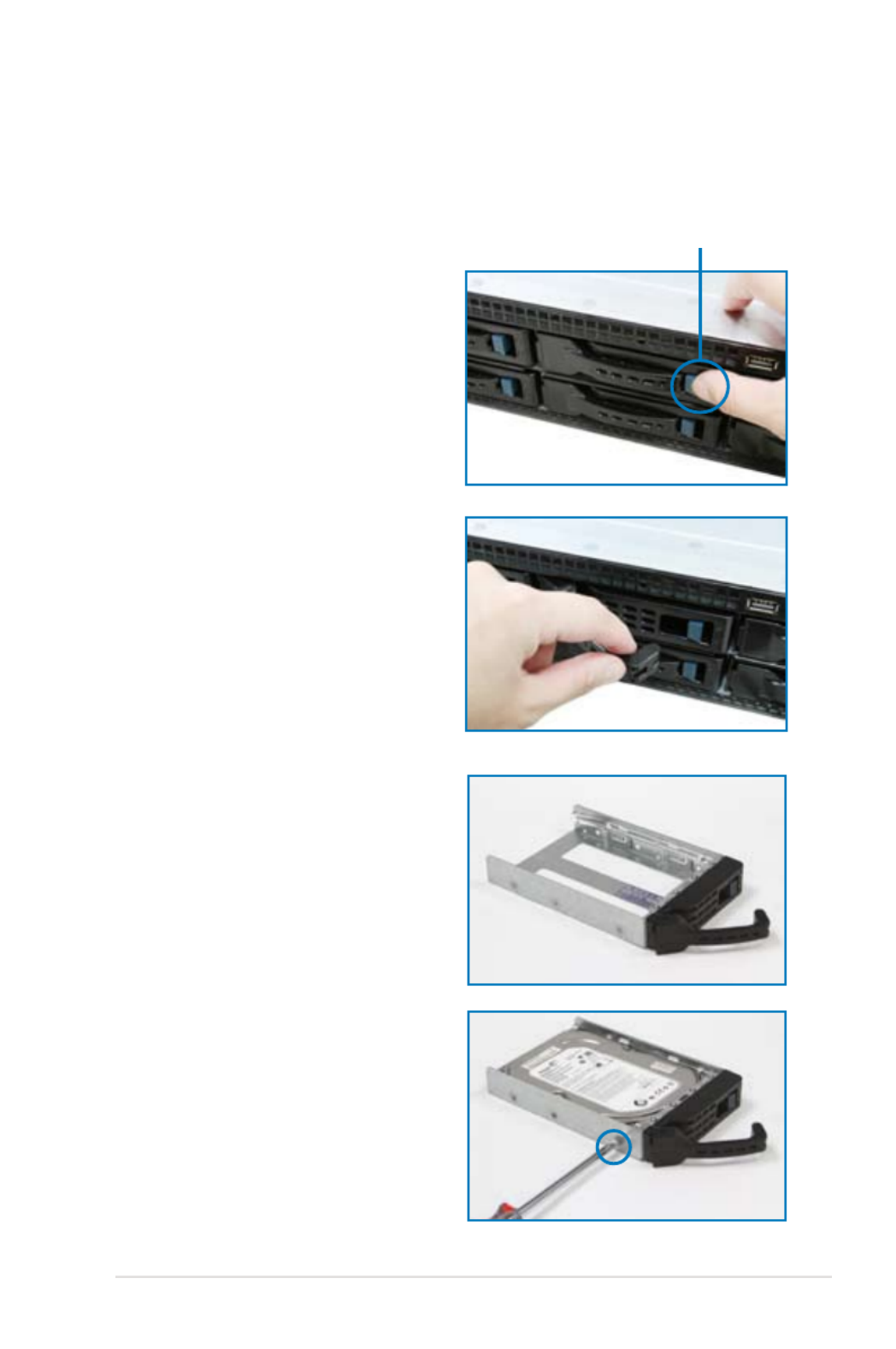
2.4 Hard disk drives
The system supports eight hot-swap SATAII/SAS hard disk drives. The hard disk
drive installed on the drive tray connects to the motherboard SATAII/SAS ports via
the SATAII/SAS backplane.
To install a hot-swap SATAII/SAS HDD:
1. Release a drive tray by pushing the
spring lock to the right, then pulling
the tray lever outward. The drive
tray ejects slightly after you pull out
the lever.
2. Firmly hold the tray lever and pull
the drive tray out of the bay.
spring lock
3. Take note of the drive tray holes.
Each side has three holes to t
different types of hard disk drives.
Use two screws on each side to
secure the hard disk drive.
4. Place a SATAII/SAS hard disk drive
on the tray, then secure it with four
screws.

Chapter 2: Hardware setup2-14
5. Carefully insert the drive tray and
push it all the way to the depth of
the bay until just a small fraction of
the tray edge protrudes.
6. Push the tray lever until it clicks, and
secures the drive tray in place. The
drive tray is correctly placed when
its front edge aligns with the bay
edge.
7. Repeat steps 1 to 6 if you wish to
install a second SATAII/SAS drive.
When installed, the SATAII/SAS connector on the drive connects to the SATAII/
SAS interface on the backplane.

2-15ASUS RS920-E7/RS8; RS926-E7/RS8
2.5 Expansion slot
2.5.1 Installing an expansion card to the riser card bracket
The barebone server comes with a riser card bracket. You need to remove the
bracket if you want to install PCI Express x16 expansion cards.
To install a PCI Express x16 card
4. Install a PCI Express x16 card to
the bracket as shown, and then
secure the card with a screw.
2. Place the riser card bracket on a
at and stable surface, and then
remove the screw from the slot bay.
PCI Express x16 slot
1. Loosen the screws of the riser card
bracket.
3. Loosen the screw of rear end
bracket and remove it.

Chapter 2: Hardware setup2-16
5. Firmly hold the bracket, and then
press it down to the slot of the
motherboard.
6. Secure the screw in front of the
GPU computing module bracket.

2-17ASUS RS920-E7/RS8; RS926-E7/RS8
* These IRQs are usually available for ISA or PCI devices.
IRQ Priority Standard function
01 System Timer
1 Keyboard Controller2
2- Programmable Interrupt
3* 11 Communications Port (COM2)
4* 12 Communications Port (COM1)
5* 13 --
6 14 Floppy Disk Controller
7* 15 --
8 System CMOS/Real Time Clock3
9* 4 ACPI Mode when used
10* 5 IRQ Holder for PCI Steering
11* 6 IRQ Holder for PCI Steering
12* PS/2 Compatible Mouse Port7
13 Numeric Data Processor8
14* 9 Primary IDE Channel
15* 10 Secondary IDE Channel
2.5.2 Conguringanexpansioncard
After installing the expansion card, congure the it by adjusting the software
settings.
1. Turn on the system and change the necessary BIOS settings, if any. See
Chapter 5 for information on BIOS setup.
2. Assign an IRQ to the card. Refer to the tables on the next page.
3. Install the software drivers for the expansion card.
Standard Interrupt assignments

Chapter 2: Hardware setup2-18
Pre-connected system cables
1. 24-pin SSI power connector (from power supply to motherboard)
2. 8-pin SSI power connector (from power supply to motherboard)
3. System fan connectors (from motherboard FRNT_FAN1, FRNT_FAN2
FRNT_FAN3, FRNT_FAN4, and FRNT_FAN5 to system fans)
4. USB connector (from motherboard to front I/O board)
5. Power Supply SMBUS connector
6. Auxiliary Panel connector (from motherboard to front I/O board)
7. Panel connector (from motherboard to front I/O board)
8. SATA connectors (from motherboard to SATAII/SAS backplane board)
9. SAS connector (from motherboard to SATAII/SAS backplane board)
10. SGPIO 1 (Intel RAID)
11. PSGPIO 1,2 (LSI PIKE RAID)
2.6 Cable connections
• The bundled system cables are pre-connected before shipment. You do
not need to disconnect these cables unless you will remove pre-installed
components to install additional devices.
• Refer to Chapter 4 for detailed information on the connectors.
9
1
2
4
5
7
33333
8
8
6
10
11

2-19ASUS RS920-E7/RS8; RS926-E7/RS8
2.7 SATAII/SAS backplane cabling
Connects a 8-pin plug
from power supply
Connects to the Intel
® C602 SATA or PIKE SATA
/ SAS connectors on the motherboard
PSGPIO1/2: Connects
to BP the SGPIO2/3
connector to support
Intel® SCU RAID, LSI
RAIO SGPIO function.
SGPIO_SEL: Set to pin 1-2 to enable onboard
C602 SATA SGPIO function (default) or set to
pin 2-3 enable optional PIKE SAS RAID, Intel
®
SCU SGPIO function
J1: Connects to the
power connector of
the slim-type optical
drive
Onboard SGPIO1
connects to BP the
SGPIO1 connector
to support Intel® RST
SGPIO function

Chapter 2: Hardware setup2-20
2.8 Removable/optional components
You may need to remove previously installed system components when installing
or removing system devices. Or you may need to install the optional components
into the system. This section tells how to remove/install the following components:
1. System fans
2. Redundant power supply units
3. ASUS PIKE RAID card (optional)
Ensure that the system is turned off before removing any components.
2.8.1 System fans
To uninstall the system fans
1. Disconnect the system fan cable
from the fan connector on the
motherboard.
2. Carefully remove the system fan
cable from the cable holder.

2-21ASUS RS920-E7/RS8; RS926-E7/RS8
3. Lift the fan, and then set aside.
4. Repeat steps 1 to 3 to uninstall the
other system fans.
To reinstall the system fans
1. Insert the fan into the fan cage.
The airow directional arrow on the
fan side should point towards the
system rear panel.
2. Insert the system fan cable into
the cable holder, then connect the
cable to the fan connector on the
motherboard.
2.8.2 Redundant power supply units
To remove the power supply unit (PSU)
1. Lift up the PSU lever.

Chapter 2: Hardware setup2-22
3. Firmly pull the PSU out of the
system chassis.
2. Hold the PSU lever and press the
PSU latch.
To install a second PSU
1. Insert the PSU into the empty PSU
bay.
2. Hold the PSU lever and press the
PSU latch. Firmly insert the PSU
into the server chassis.

2-23ASUS RS920-E7/RS8; RS926-E7/RS8
• If you install two power supply units in the system, you can switch the
working behavior of the two PSUs between
1+1jumpermode and 2+0
jumpermode.
1+1jumpermode: If the total power consumption of the system is less
than 1400W, the system can be booted using one PSU and the PSU hot-
swap feature is supported. If the total power consumption of the system
exceeds 1400W, the maximum output power of the PSUs can reach to
2800W with PSU hot-swap feature disabled, and the system shuts down if
any of the PSUs is removed.
2+0jumpermode: The system can be booted only when two PSUs are
installed. The maximum output power of the PSUs can reach to 2800W with
PSU hot-swap feature disabled, and the system shuts down if any of the
PSUs is removed.
• The output power varies with different input voltages. Refer to the table
below for details.
SKU Input Voltage Max. Output Power (Watt)
1620W 100V—140V 1100W
180V—240V 1400W
2.8.3 Installing ASUS PIKE RAID card (optional)
Follow the steps below to install an optional ASUS RAID card on your motherboard.
If you install the PIKE 2108 Series SAS RAID card, follow steps 1 and 2 to remove
the outer heatsink on RAID card.
1. Remove the two screws that secure
the heatsink bracket on the back of
the SAS RAID card.
Heatsink bracket

2-25ASUS RS920-E7/RS8; RS926-E7/RS8
5. Align the golden ngers of the RAID
card with the PIKE RAID card slot
then insert the RAID card into the
PIKE RAID card slot. Ensure that it
is completely seated in place, then
secure the PIKE card with the screw
you removed earlier.
6. Connect the data cables in
numerical order, from SATA1-5
to the SAS connectors labeled
PSAS1-4 (Blue) and 5 (Black) on
the motherboard.

2-
This chapter describes how to install
the optional components and devices
into the barebone server.
Chapter 3
Installation options

Chapter 3: Installation options3-4
Do not install the rail kit in the following situation:
DO NOT place the rail hook on a thick lip
of the mounting hole.
DO NOT install the rail to the outer side of
the server rack.
6. When mounting the server to the rack,
ensure to include the side knots on the
two sides of the server in the rack rail
holders, as shown in the right gure.

Chapter 3: Installation options3-6

4-2 Chapter 4: Motherboard information
4.1 Motherboard layout
Layout contents
Jumpers Page
1. Clear RTC RAM (CLRTC1) 4-4
2. VGA controller setting (3-pin VGA_SW1) 4-5
3. LSI MegaRAID or Intel RSTe selection jumper (3-pin
RAID_SEL1) 4-5
4. LAN controller setting (3-pin LAN_SW1) 4-6
5. ME rmware force recovery setting (3-pin ME_RCVR1) 4-6
6. DIMM thermal trip Setting (3-pin DIMMTRIP1) 4-7
7. BMC Setting (3-pin BMC_SW1) 4-7

ASUS RS920-E7/RS8; RS926-E7/RS8 4-3
Internal connectors Page
1. Serial ATA 6.0/3.0 Gb/s connectors (7-pin SATA6G_1-2 [black])
(7-pin SATA3G_3-6 [ ])black 4-8
2. ISAS connectors 4-9
3. PSAS connectors 4-9
4. USB connectors (10-1 pin USB56, A-Type USB10) 4-10
5. Hard disk activity LED connector (4-pin HDLED1) 4-10
6. CPU and front fan connectors (4-pin CPU_FAN1-2,
FRNT_FAN1–5) 4-11
7. Serial General Purpose Input/Output connectors
(6-1 pin SGPIO1, 8-1 pin PSGPIO 1/2 and ISGPIO1) 4-12
8. Serial port connector (10-1 pin COM1) 4-13
9. TPM connector (20-1 pin TPM1) 4-13
10. Power Supply SMBus connector (6-1 pin PSUSMB1) 4-14
11. EATX power connectors (24-pin ATXPWR1, 8-pin ATX12V1) 4-15
12. System panel connector (20-1 pin PANEL1) 4-16
13. Auxiliary panel connector (20-2pin AUX_PANEL1) 4-17
Internal LEDs Page
1. Standby Power LED (SB_PWR1) 4-18
2. DIMM Error LED (ERR_DIMM) 4-18
3. CPU warning LED (ERR_CPU1/2/3/4) 4-19
4. CATT Error LED (CATTERR_LED1) 4-19
5. Baseboard Management Controller LED (BMC_LED1) 4-20
6. Q-Code LED (LED1_LED2) 4-20

4-4 Chapter 4: Motherboard information
4.2 Jumpers
1. Clear RTC RAM (CLRTC1)
This jumper allows you to clear the Real Time Clock (RTC) RAM in CMOS.
You can clear the CMOS memory of date, time, and system setup parameters
by erasing the CMOS RTC RAM data. The onboard button cell battery
powers the RAM data in CMOS, which include system setup information such
as system passwords.
To erase the RTC RAM:
1. Turn OFF the computer and unplug the power cord.
2. Move the jumper cap from pins 1–2 (default) to pins 2–3. Keep the cap
on pins 2–3 for about 5–10 seconds, then move the cap back to pins 1–
2.
3. Plug the power cord and turn ON the computer.
4. Hold down the <Del> key during the boot process and enter BIOS setup
to re-enter data.
Except when clearing the RTC RAM, never remove the cap on CLRTC jumper
default position. Removing the cap will cause system boot failure!
If the steps above do not help, remove the onboard battery and move the
jumper again to clear the CMOS RTC RAM data. After the CMOS clearance,
reinstall the battery.

ASUS RS920-E7/RS8; RS926-E7/RS8 4-5
2. VGA controller setting (3-pin VGA_SW1)
This jumper allows you to enable or disable the onboard VGA controller. Set
to pins 1–2 to activate the VGA feature.
3. LSIMegaRAIDorIntelRSTeselectionjumper(3-pinRAID_SEL1)
This jumper allows you to select the PCH SATA RAID mode to use LSI
MegaRAID software or Intel® Rapid Storage Technology enterprise 3.0 RAID.
Place the jumper caps over pins 1–2 if you want to use the LSI MegaRAID
software RAID Utility (default); otherwise, place the jumper caps to pins 2–3
to use the Intel® Rapid Storage Technology Enterprise Option ROM Utility.

4-8 Chapter 4: Motherboard information
4.3 Internal connectors
1. Serial ATA 6.0/3.0 Gb/s connectors
(7-pin SATA6G_1-2 [black])
(7-pin SATA3G_3-6 [black])
Supported by the Intel® C602 Chipset, these connectors are for the Serial ATA
signal cables for Serial ATA hard disk drives that allows up to 6Gb/s of data
transfer rate.
If you installed Serial ATA hard disk drives, you can create a RAID 0, RAID 1,
RAID 10, or RAID 5 conguration.
The actual data transfer rate depends on the speed of Serial ATA hard disks
installed.
ASUS RS920-E7/RS8; RS926-E7/RS8 4-11
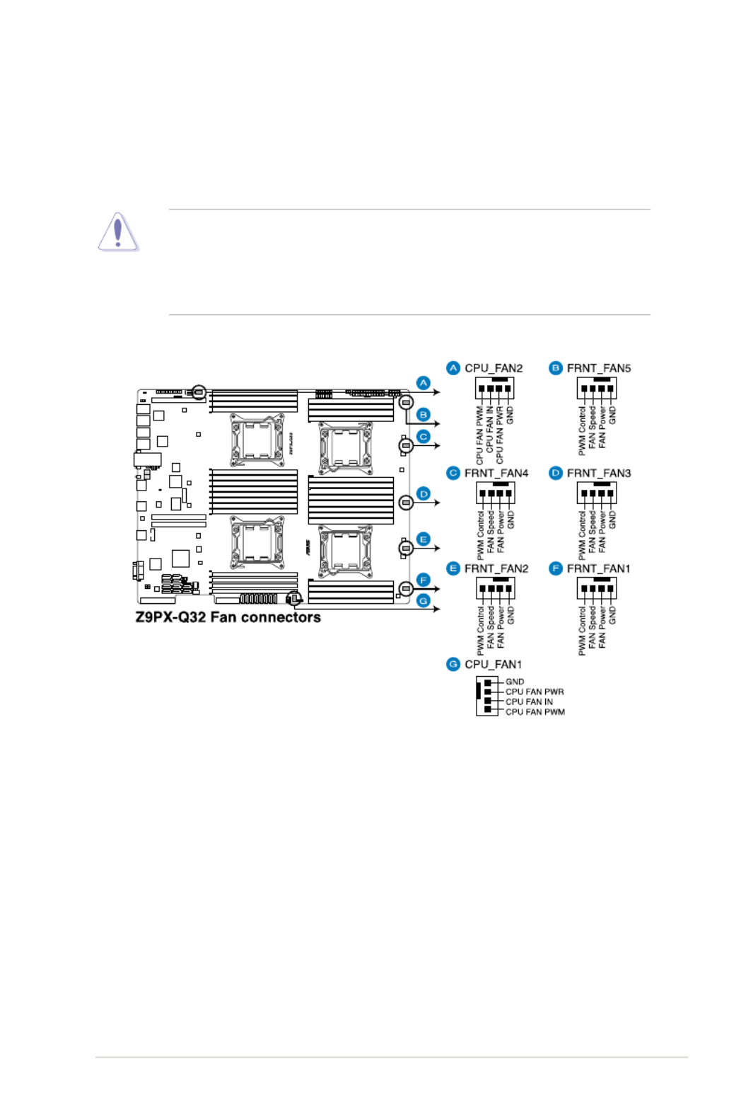
6. CPU and front fan connectors (4-pin CPU_FAN1-2, FRNT_FAN1–5)
The fan connectors support cooling fans. Connect the fan cables to the fan
connectors on the motherboard, ensuring that the black wire of each cable
matches the ground pin of the connector.
• DO NOT forget to connect the fan cables to the fan connectors. Insufcient
air ow inside the system may damage the motherboard components.
• These are not jumpers! DO NOT place jumper caps on the fan connectors!
• All fans feature the ASUS Smart Fan technology.

4-12 Chapter 4: Motherboard information
7. Serial General Purpose Input/Output connectors
(6-1 pin SGPIO1, 8-1 pin PSGPIO 1/2 and ISGPIO1)
The SGPIO 1 connectors are used for the Intel Rapid Storage Technology
Enterprise SGPIO interface that controls the LED pattern generation, device
information and general purpose data.
The PSGPIO 1/2 connectors are used for PIKE card.
The ISGPIO 1 connector is for SATA connectors—ISAS connectors.

4-14 Chapter 4: Motherboard information
10. Power Supply SMBus connector (6-1 pin PSUSMB1)
This connector allows you to connect SMBus (System Management Bus) to
the power supply unit to read PSU information. Devices communicate with an
SMBus host and/or other SMBus devices using the SMBus interface.

ASUS RS920-E7/RS8; RS926-E7/RS8 4-15
11. EATX power connectors (24-pin ATXPWR1, 8-pin ATX12V1)
These connectors are for an EATX power supply plugs. The power supply
plugs are designed to t these connectors in only one orientation. Find the
proper orientation and push down rmly until the connectors completely t.
• DO NOT forget to connect the 24+8-pin power plugs; otherwise, the system
will not boot up.
• Use of a PSU with a higher power output is recommended when conguring
a system with more power-consuming devices. The system may become
unstable or may not boot up if the power is inadequate.
• This motherboard supports EATX2.0 PSU or later version.
• Ensure that your power supply unit (PSU) can provide at least the minimum
power required by your system.
Produktspezifikationen
| Marke: | Asus |
| Kategorie: | Server |
| Modell: | RS920-E7/RS8 |
| Breite: | 444 mm |
| Tiefe: | 750 mm |
| Gewicht: | 20000 g |
| Höhe: | 88 mm |
| Anzahl USB 2.0 Anschlüsse: | 6 |
| Betriebstemperatur: | 10 - 35 °C |
| Eingebauter Ethernet-Anschluss: | Ja |
| Anzahl Ethernet-LAN-Anschlüsse (RJ-45): | 5 |
| Ethernet LAN Datentransferraten: | 10,100,1000 Mbit/s |
| Stromversorgung: | 1620 W |
| Temperaturbereich bei Lagerung: | -40 - 70 °C |
| Luftfeuchtigkeit bei Lagerung: | 20 - 90 % |
| Grafikkarte: | AST2300 |
| Prozessorfamilie: | Intel |
| Kompatible Betriebssysteme: | CentOS 5.6 32/64-bit, Windows Server 2008 R2, Windows Server 2008 R2 Enterprise, Windows Server 2008 Enterprise 32/64-bit, RedHat Enterprise Linux AS5.6/6.0 32/64-bit, SuSE Linux Enterprise Server 11.2 32/64-bit, VMWare ESX4.1/ESXi4.1 |
| Anzahl der unterstützten Speicherlaufwerke: | 8 |
| RAID Level: | 0, 1,5, 10 |
| Gehäusetyp: | Rack (2U) |
| Prozessorsockel: | LGA 2011 (Socket R) |
| Anzahl VGA (D-Sub) Anschlüsse: | 1 |
| Kompatible Prozessoren: | Intel® Xeon® |
| Motherboard Chipsatz: | Intel® C602 |
| Unterstützte Arbeitsspeicher: | DDR3-SDRAM |
| Unterstützte Speicherlaufwerk-Schnittstellen: | Serial Attached SCSI (SAS), Serial ATA II, Serial ATA III |
| Maximaler Grafikkartenspeicher: | 16 MB |
| Anzahl PS/2 Anschlüsse: | 1 |
| Ethernet Schnittstellen Typ: | Fast Ethernet, Gigabit Ethernet |
| LAN-Controller: | Intel® I350-AM4 |
| Anzahl serielle Anschlüsse: | 1 |
| Sicherheit: | CE, EN55022 |
| Grafikkarte-Familie: | Aspeed |
| PCI-Express x16-Slots: | 4 |
| Unterstützung für redundantes Netzteil: | Ja |
| Anzahl unterstützter Prozessoren: | 4 |
| PCI-Express x8-Slots: | 2 |
| Zahl der DIMM Slots: | 32 |
| Unterstützte RDIMM Taktraten: | 800,1066,1333,1600 MHz |
| unterstützte Speicherlaufwerksgrößen: | 3.5 Zoll |
| HDD Laufwerkschächte Hot-Swap: | Ja |
| Intel® Xeon-Serie: | E5-4600 |
| Maximaler RDIMM Speicher: | 1024 GB |
| Unterstützte DIMM-Modulkapazitäten: | 16GB, 1GB, 2GB, 4GB, 8GB |
| Unterstützte UDIMM Taktraten: | 1066,1333 MHz |
| Maximaler UDIMM Speicher: | 256 GB |
Brauchst du Hilfe?
Wenn Sie Hilfe mit Asus RS920-E7/RS8 benötigen, stellen Sie unten eine Frage und andere Benutzer werden Ihnen antworten
Bedienungsanleitung Server Asus

31 August 2024
28 August 2024
20 August 2024
19 August 2024
16 August 2024
9 August 2024
8 August 2024
8 August 2024
7 August 2024
2 August 2024
Bedienungsanleitung Server
- Server Acer
- Server Gigabyte
- Server HP
- Server Medion
- Server Sony
- Server ZyXEL
- Server Buffalo
- Server Allnet
- Server Linksys
- Server Netgear
- Server Fantec
- Server Technics
- Server Abus
- Server Megasat
- Server Toshiba
- Server Lindy
- Server Dell
- Server Lenovo
- Server Tripp Lite
- Server TRENDnet
- Server Western Digital
- Server AVerMedia
- Server Veritas
- Server Black Box
- Server Supermicro
- Server SilverStone
- Server NEC
- Server Monacor
- Server Seagate
- Server Fujitsu
- Server Maxdata
- Server Revox
- Server Totolink
- Server Conceptronic
- Server D-Link
- Server QNAP
- Server Digitus
- Server LevelOne
- Server APC
- Server Cisco
- Server Freecom
- Server Synology
- Server Kramer
- Server Intellinet
- Server Eaton
- Server Hikvision
- Server FLIR
- Server ELAC
- Server Planet
- Server Asustor
- Server Blackmagic Design
- Server Dane Elec
- Server Digi
- Server Dual Bay
- Server EMC
- Server GeoVision
- Server Ibm
- Server In Win
- Server Iomega
- Server LaCie
- Server Provision ISR
- Server Quantum
- Server Sun
- Server AMX
- Server ACTi
- Server Vimar
- Server Siig
- Server Intel
- Server Moxa
- Server StarTech.com
- Server Smart-AVI
- Server Mobotix
- Server Sonnet
- Server SEH
- Server Gefen
- Server Avocent
- Server Atlantis Land
- Server Hanwha
- Server ATen
- Server KanexPro
- Server Axis
- Server Advantech
- Server HGST
- Server Kiloview
- Server B&B Electronics
- Server Extron
- Server Atlona
- Server Rocstor
- Server Raidsonic
- Server G-Technology
- Server Infortrend
- Server Areca
- Server Silex
- Server Promise Technology
- Server Matrox
- Server Origin Storage
- Server Ernitec
- Server EXSYS
- Server Raritan
- Server C2G
- Server Chenbro Micom
- Server Lantronix
- Server IStarUSA
- Server Valcom
- Server TAIDEN
- Server MvixUSA
- Server Opengear
- Server Mr. Signal
- Server NETSCOUT
Neueste Bedienungsanleitung für -Kategorien-

13 Oktober 2024

12 Oktober 2024
12 Oktober 2024

11 Oktober 2024
11 Oktober 2024

10 Oktober 2024
6 Oktober 2024

4 Oktober 2024
3 Oktober 2024
3 Oktober 2024