Asus P8Z68-V/GEN3 Bedienungsanleitung
Asus
Hauptplatine
P8Z68-V/GEN3
Lesen Sie kostenlos die 📖 deutsche Bedienungsanleitung für Asus P8Z68-V/GEN3 (145 Seiten) in der Kategorie Hauptplatine. Dieser Bedienungsanleitung war für 8 Personen hilfreich und wurde von 2 Benutzern mit durchschnittlich 4.5 Sternen bewertet
Seite 1/145

Motherboard
P8Z68-V/GEN3

ii
E6849
First Edition
Septemper 2011
Copyright © 2011 ASUSTeK COMPUTER INC. All Rights Reserved.
No part of this manual, including the products and software described in it, may be reproduced,
transmitted, transcribed, stored in a retrieval system, or translated into any language in any form or by any
means, except documentation kept by the purchaser for backup purposes, without the express written
permission of ASUSTeK COMPUTER INC. (“ASUS”).
Product warranty or service will not be extended if: (1) the product is repaired, modied or altered, unless
such repair, modication of alteration is authorized in writing by ASUS; or (2) the serial number of the
product is defaced or missing.
ASUS PROVIDES THIS MANUAL “AS IS” WITHOUT WARRANTY OF ANY KIND, EITHER EXPRESS
OR IMPLIED, INCLUDING BUT NOT LIMITED TO THE IMPLIED WARRANTIES OR CONDITIONS OF
MERCHANTABILITY OR FITNESS FOR A PARTICULAR PURPOSE. IN NO EVENT SHALL ASUS, ITS
DIRECTORS, OFFICERS, EMPLOYEES OR AGENTS BE LIABLE FOR ANY INDIRECT, SPECIAL,
INCIDENTAL, OR CONSEQUENTIAL DAMAGES (INCLUDING DAMAGES FOR LOSS OF PROFITS,
LOSS OF BUSINESS, LOSS OF USE OR DATA, INTERRUPTION OF BUSINESS AND THE LIKE),
EVEN IF ASUS HAS BEEN ADVISED OF THE POSSIBILITY OF SUCH DAMAGES ARISING FROM ANY
DEFECT OR ERROR IN THIS MANUAL OR PRODUCT.
SPECIFICATIONS AND INFORMATION CONTAINED IN THIS MANUAL ARE FURNISHED FOR
INFORMATIONAL USE ONLY, AND ARE SUBJECT TO CHANGE AT ANY TIME WITHOUT NOTICE,
AND SHOULD NOT BE CONSTRUED AS A COMMITMENT BY ASUS. ASUS ASSUMES NO
RESPONSIBILITY OR LIABILITY FOR ANY ERRORS OR INACCURACIES THAT MAY APPEAR IN THIS
MANUAL, INCLUDING THE PRODUCTS AND SOFTWARE DESCRIBED IN IT.
Products and corporate names appearing in this manual may or may not be registered trademarks or
copyrights of their respective companies, and are used only for identication or explanation and to the
owners’ benet, without intent to infringe.
Offer to Provide Source Code of Certain Software
This product may contain copyrighted software that is licensed under the General Public License (“GPL”)
and under the Lesser General Public License Version (“LGPL”). The GPL and LGPL licensed code in this
product is distributed without any warranty. Copies of these licenses are included in this product.
You may obtain the complete corresponding source code (as dened in the GPL) for the GPL Software,
and/or the complete corresponding source code of the LGPL Software (with the complete machine-
readable “work that uses the Library”) for a period of three years after our last shipment of the product
including the GPL Software and/or LGPL Software, which will be no earlier than December 1, 2011, either
(1) for free by downloading it from http://support.asus.com/download;
or
(2) for the cost of reproduction and shipment, which is dependent on the preferred carrier and the location
where you want to have it shipped to, by sending a request to:
ASUSTeK Computer Inc.
Legal Compliance Dept.
15 Li Te Rd.,
Beitou, Taipei 112
Taiwan
In your request please provide the name, model number and version, as stated in the About Box of the
product for which you wish to obtain the corresponding source code and your contact details so that we
can coordinate the terms and cost of shipment with you.
The source code will be distributed WITHOUT ANY WARRANTY and licensed under the same license as
the corresponding binary/object code.
This offer is valid to anyone in receipt of this information.
ASUSTeK is eager to duly provide complete source code as required under various Free Open Source
Software licenses. If however you encounter any problems in obtaining the full corresponding source code
we would be much obliged if you give us a notication to the email address gpl@asus.com, stating the
product and describing the problem (please do NOT send large attachments such as source code archives
etc to this email address).

iii
Contents
Notices ....................................................................................................................... vi
Safety information ..................................................................................................... vii
About this guide ....................................................................................................... viii
P8Z68-V/GEN3 specications summary ................................................................... x
Chapter 1: Product introduction
1.1 Welcome! .................................................................................................... 1-1
1.2 Package contents.......................................................................................1-1
1.3 Special features..........................................................................................1-2
1.3.1 Product highlights........................................................................1-2
1.3.2 Dual Intelligent Processors 2 with DIGI+ VRM ...........................1-3
1.3.3 ASUS Exclusive Features ...........................................................1-4
1.3.4 ASUS Quiet Thermal Solution .....................................................1-4
1.3.5 ASUS EZ DIY ..............................................................................1-5
1.3.6 Other special features .................................................................1-6
Chapter 2: Hardware information
2.1 Before you proceed ................................................................................... 2-1
2.2 Motherboard overview ...............................................................................2-2
2.2.1 Motherboard layout .....................................................................2-2
2.2.2 Central Processing Unit (CPU) ...................................................2-4
2.2.3 System memory ..........................................................................2-5
2.2.4 Expansion slots .........................................................................2-12
2.2.5 Onboard switches .....................................................................2-14
2.2.6 Onboard LEDs ..........................................................................2-18
2.2.7 Jumper ......................................................................................2-20
2.2.8 Internal connectors....................................................................2-21
2.3 Building your computer system .............................................................2-30
2.3.1 Additional tools and components to build a PC system ............2-30
2.3.2 CPU installation......................................................................... 2-31
2.3.3 CPU heatsink and fan assembly installation .............................2-33
2.3.4 DIMM installation....................................................................... 2-35
2.3.5 Motherboard installation ............................................................ 2-36
2.3.6 ATX Power connection .............................................................. 2-38
2.3.7 SATA device connection ............................................................ 2-39
2.3.8 Front I/O Connector ..................................................................2-40
2.3.9 Expansion Card installation.......................................................2-41
2.3.10 Rear panel connection ..............................................................2-42
2.3.11 Audio I/O connections ...............................................................2-45

iv
Contents
2.4 Starting up for the rst time .................................................................... 2-48
2.5 Turning off the computer .........................................................................2-48
Chapter 3: BIOS setup
3.1 Knowing BIOS ............................................................................................ 3-1
3.2 BIOS setup program ..................................................................................3-1
3.2.1 EZ Mode...................................................................................... 3-2
3.2.2 Advanced Mode ..........................................................................3-3
3.3 Main menu ..................................................................................................3-5
3.4 Ai Tweaker menu ........................................................................................3-7
3.5 Advanced menu .......................................................................................3-14
3.5.1 CPU Conguration ....................................................................3-15
3.5.2 System Agent Conguration...................................................... 3-17
3.5.3 PCH Conguration ....................................................................3-17
3.5.4 SATA Conguration ...................................................................3-18
3.5.5 USB Conguration ....................................................................3-20
3.5.6 Onboard Devices Conguration ................................................3-21
3.5.7 APM ..........................................................................................3-24
3.6 Monitor menu ...........................................................................................3-25
3.7 Boot menu ................................................................................................3-28
3.8 Tools menu ...............................................................................................3-29
3.8.1 ASUS EZ Flash 2 Utility ............................................................3-29
3.8.2. ASUS O.C. Prole .....................................................................3-30
3.9 Exit menu ..................................................................................................3-31
3.10 Updating BIOS ..........................................................................................3-32
3.10.1 ASUS Update utility................................................................... 3-32
3.10.2 ASUS EZ Flash 2 utility .............................................................3-35
3.10.3 ASUS CrashFree BIOS 3 utility.................................................3-36
3.10.4 ASUS BIOS Updater .................................................................3-37
Chapter 4: Software support
4.1 Installing an operating system ................................................................. 4-1
4.2 Support DVD information ..........................................................................4-1
4.2.1 Running the support DVD ...........................................................4-1
4.2.2 Obtaining the software manuals.................................................. 4-2
4.3 Software information .................................................................................4-3
4.3.1 AI Suite II..................................................................................... 4-3
4.3.2 DIGI+ VRM ..................................................................................4-4
4.3.3 BT GO! ........................................................................................4-5
4.3.4 TurboV EVO ................................................................................4-7

v
4.3.5 EPU ........................................................................................... 4-12
4.3.6 ASUS FAN Xpert .......................................................................4-13
4.3.7 ASUS Probe II ...........................................................................4-14
4.3.8 Ai Charger+ ...............................................................................4-15
4.3.9 Audio congurations.................................................................. 4-16
4.4 RAID congurations ................................................................................4-17
4.4.1 RAID denitions ........................................................................4-17
4.4.2 Installing Serial ATA hard disks .................................................4-18
4.4.3 Setting the RAID item in BIOS ..................................................4-18
4.4.4 Intel® Rapid Storage Technology Option ROM utility ................ 4-18
4.5 Creating a RAID driver disk.....................................................................4-24
4.5.1 Creating a RAID driver disk without entering the OS ................4-24
4.5.2 Creating a RAID driver disk in Windows
® .................................. 4-24
4.5.3 Installing the RAID driver during Windows
® OS installation ...... 4-25
4.5.4 Using a USB oppy disk drive ...................................................4-26
Chapter 5: Multiple GPU technology support
5.1 ATI® CrossFireX™ technology .................................................................. 5-1
5.1.1 Requirements ..............................................................................5-1
5.1.2 Before you begin .........................................................................5-1
5.1.3 Installing two CrossFireX™ graphics cards ................................5-2
5.1.4 Installing the device drivers .........................................................5-3
5.1.5 Enabling the ATI® CrossFireX™ technology ............................... 5-3
5.2 NVIDIA® SLI™ technology ......................................................................... 5-4
5.2.1 Requirements ..............................................................................5-4
5.2.2 Installing two SLI-ready graphics cards ......................................5-4
5.2.3 Installing the device drivers .........................................................5-5
5.2.4 Enabling the NVIDIA
® SLI™ technology ..................................... 5-5
5.3 LucidLogix® Virtu™ solution ..................................................................... 5-8
5.3.1 Hardware installation................................................................... 5-8
5.3.2 Software conguration ................................................................5-9
Contents

vi
Notices
Federal Communications Commission Statement
This device complies with Part 15 of the FCC Rules. Operation is subject to the following two
conditions:
• This device may not cause harmful interference, and
• This device must accept any interference received including interference that may cause
undesired operation.
This equipment has been tested and found to comply with the limits for a Class B digital
device, pursuant to Part 15 of the FCC Rules. These limits are designed to provide
reasonable protection against harmful interference in a residential installation. This
equipment generates, uses and can radiate radio frequency energy and, if not installed
and used in accordance with manufacturer’s instructions, may cause harmful interference
to radio communications. However, there is no guarantee that interference will not occur
in a particular installation. If this equipment does cause harmful interference to radio or
television reception, which can be determined by turning the equipment off and on, the user
is encouraged to try to correct the interference by one or more of the following measures:
•
Reorient or relocate the receiving antenna.
•
Increase the separation between the equipment and receiver.
•
Connect the equipment to an outlet on a circuit different from that to which the receiver is
connected.
•
Consult the dealer or an experienced radio/TV technician for help.
Canadian Department of Communications Statement
This digital apparatus does not exceed the Class B limits for radio noise emissions from
digital apparatus set out in the Radio Interference Regulations of the Canadian Department
of Communications.
This class B digital apparatus complies with Canadian ICES-003.
The use of shielded cables for connection of the monitor to the graphics card is required
to assure compliance with FCC regulations. Changes or modications to this unit not
expressly approved by the party responsible for compliance could void the user’s authority
to operate this equipment.
REACH
Complying with the REACH (Registration, Evaluation, Authorisation, and Restriction of
Chemicals) regulatory framework, we published the chemical substances in our products at
ASUS REACH website at http://csr.asus.com/english/REACH.htm.
DO NOT throw the motherboard in municipal waste. This product has been designed to
enable proper reuse of parts and recycling. This symbol of the crossed out wheeled bin
indicates that the product (electrical and electronic equipment) should not be placed in
municipal waste. Check local regulations for disposal of electronic products.
DO NOT throw the mercury-containing button cell battery in municipal waste. This symbol
of the crossed out wheeled bin indicates that the battery should not be placed in municipal
waste.

vii
Safety information
Electrical safety
• To prevent electrical shock hazard, disconnect the power cable from the electrical outlet
before relocating the system.
• When adding or removing devices to or from the system, ensure that the power cables
for the devices are unplugged before the signal cables are connected. If possible,
disconnect all power cables from the existing system before you add a device.
• Before connecting or removing signal cables from the motherboard, ensure that all
power cables are unplugged.
• Seek professional assistance before using an adapter or extension cord. These devices
could interrupt the grounding circuit.
• Ensure that your power supply is set to the correct voltage in your area. If you are not sure
about the voltage of the electrical outlet you are using, contact your local power company.
• If the power supply is broken, do not try to x it by yourself. Contact a qualied service
technician or your retailer.
Operation safety
• Before installing the motherboard and adding devices on it, carefully read all the manuals
that came with the package.
• Before using the product, ensure all cables are correctly connected and the power
cables are not damaged. If you detect any damage, contact your dealer immediately.
• To avoid short circuits, keep paper clips, screws, and staples away from connectors,
slots, sockets and circuitry.
• Avoid dust, humidity, and temperature extremes. Do not place the product in any area
where it may become wet.
• Place the product on a stable surface.
• If you encounter technical problems with the product, contact a qualied service
technician or your retailer.

viii
About this guide
This user guide contains the information you need when installing and conguring the motherboard.
How this guide is organized
This guide contains the following parts:
• Chapter 1: Product introduction
This chapter describes the features of the motherboard and the new technology it
supports.
• Chapter 2: Hardware information
This chapter lists the hardware setup procedures that you have to perform when
installing system components. It includes description of the switches, jumpers, and
connectors on the motherboard.
• Chapter 3: BIOS setup
This chapter tells how to change system settings through the BIOS Setup menus.
Detailed descriptions of the BIOS parameters are also provided.
• Chapter 4: Software support
This chapter describes the contents of the support DVD that comes with the
motherboard package and the software.
• Chapter 5: Multiple GPU technology support
This chapter describes how to install and congure multiple ATI
® CrossFireX™ and
NVIDIA® SLI™ graphics cards.
Where to nd more information
Refer to the following sources for additional information and for product and software updates.
1. ASUS websites
The ASUS website provides updated information on ASUS hardware and software
products. Refer to the ASUS contact information.
2. Optional documentation
Your product package may include optional documentation, such as warranty yers,
that may have been added by your dealer. These documents are not part of the
standard package.

ix
Conventions used in this guide
To ensure that you perform certain tasks properly, take note of the following symbols used
throughout this manual.
Typography
Bold text Indicates a menu or an item to select.
Italic
s Used to emphasize a word or a phrase.
<Key> Keys enclosed in the less-than and greater-than sign means
that you must press the enclosed key.
Example: <Enter> means that you must press the Enter or
Return key.
<Key1> + <Key2> + <Key3> If you must press two or more keys simultaneously, the key
names are linked with a plus sign (+).
Example: <Ctrl> + <Alt> + <Del>
DANGER/WARNING: Information to prevent injury to yourself when trying to
complete a task.
CAUTION: Information to prevent damage to the components when trying to
complete a task.
IMPORTANT: Instructions that you MUST follow to complete a task.
: Tips and additional information to help you complete a task.NOTE

x
P8Z68-V/GEN3 specications summary
CPU LGA1155 socket for Intel®
2nd Generation Core™ i7 / Core™ i5 /
Core™ i3 / Pentium / Celeron Processors
Supports 32nm / 22nm CPU
Supports Intel® Turbo Boost Technology 2.0*
* The Intel® Turbo Boost Technology 2.0 support depends on CPU
types.
** Refer to www.asus.com for the Intel CPU support list.
Chipset Intel
® Z68 Express Chipset
Memory 4 x DIMM, max. 32GB, DDR3 2200(O.C.)* / 2133(O.C.) /
1866(O.C.) / 1600 / 1333 / 1066 MHz, non-ECC, un-buffered memory
Dual channel memory architecture
Supports Intel® Extreme Memory Prole (XMP)
* Due to CPU behavior, DDR3 2200/2000/1800 MHz memory
module will run at DDR3 2133/1866/1600 MHz frequency as
default.
** Hyper DIMM support is subject to the physical characteristics of
individual CPUs. Some hyper DIMMs only support one DIMM
per channel. Please refer to Memory QVL for details.
*** Refer to www.asus.com or this user manual for the Memory
QVL (Qualied Vendors Lists)
Expansion slots 2 x PCI Express 3.0 / 2.0 x16 slots (single at x16 or dual at x8 / x8
mode)
1 x PCI Express 2.0 p10-x16 slot [black] (max. at p10-x4 mode, compatible
with PCIe p10-x1 and p10-x4 devices)
2 x PCI Express 2.0 p10-x1 slots
2 x PCI slots
* The PCIe x16_3 slot shares bandwidth with PCIe x1_1 slot,
PCIe x1_2 slot, USB3_34 and eSATA. The PCIe x16_3 default
setting is in p10-x1 mode.
** Actual PCIe speed depends on installed CPU type.
VGA Multi-VGA output support: HDMI, DVI-D, and RGB ports
Supports HDMI with max. resolution 1920 x 1200 @60Hz
Supports DVI with max. resolution 1920 x 1200 @60Hz
Supports RGB with max. resolution 2048 x 1536 @75Hz
Maximum shared memory of 1748MB
Multi-GPU support Supports NVIDIA
® Quad-GPU SLI™ Technology
Supports ATI® Quad-GPU CrossFireX™ Technology
Supports LucidLogix®
Virtu™ Technology*
* LucidLogix® Virtu™ Technology supports Windows
® 7 operating
systems.
Storage Intel® Z68 Express Chipset
- 2 x SATA 6.0 Gb/s ports (gray)
- 4 x SATA 3.0 Gb/s ports (blue)
- Intel® Rapid Storage Technology supports RAID 0, 1, 5, and 10
- Supports Intel® Smart Response Technology on 2nd generation
Intel
® Core™ processor family.*
* Intel
® Smart Response Technology supports Windows
® 7/
Vista operating systems.
JMicron® JMB362 SATA controller*
- 1 x eSATA 3.0 Gb/s port
* These SATA ports are for data hard drives only. ATAPI devices
are not supported.
LAN Intel® 82579 Gigabit LAN - Dual interconnect between the
Integrated LAN controller and Physical Layer (PHY)
(continued on the next page)

xi
P8Z68-V/GEN3 specications summary
Bluetooth Bluetooth v2.1 + EDR
ASUS BT GO! Utility
Audio Realtek® ALC892 8-channel High Denition Audio CODEC
- BD Audio Layer Content Protection
- Supports Jack-Detection, Multi-Streaming and
Front Panel Jack-Retasking
- Optical S/PDIF Out ports at back I/O
USB 2 x ASMedia USB 3.0 controllers
- 2 x USB 3.0 ports at mid-board for front panel support
- 2 x USB 3.0 ports at back panel (blue)
Intel® Z68 Express Chipset
- 12 x USB 2.0 ports (6 ports at mid-board, 6 ports at back panel)
ASUS unique features ASUS Dual Intelligent Processors 2 with DIGI+ VRM:
ASUS DIGI+ VRM
- Industry leading Digital 16-Phase* Power Design
- ASUS DIGI+ VRM Utility
* 12-phase for CPU, 4-phase for iGPU
ASUS EPU
- EPU, EPU switch
ASUS TPU
- Auto Tuning, TurboV, GPU Boost, TPU switch
ASUS BT GO! (Bluetooth):
- Folder Sync, BT Transfer, Shot & Send, BT to Net,
Music Player, Personal Manager
ASUS BT Turbo Remote:
- Exclusive Smartphone Interface supporting iPhone,
Android, Windows Mobile and Symbian systems
ASUS Exclusive Features
- ASUS UEFI BIOS EZ Mode featuring friendly graphics user
interface
- MemOK!
- AI Suite II
- AI Charger+
- Anti Surge
- Disk Unlocker
ASUS Quiet Thermal Solutions
- ASUS Fanless Design: Heat-sink solution
- ASUS Fan Xpert
ASUS EZ DIY
- ASUS Q-Shield
- ASUS Q-Connector
- ASUS O.C. Tuner
- ASUS CrashFree BIOS 3
- ASUS EZ Flash 2
ASUS Q-Design ASUS Q-LED (CPU, DRAM, VGA, Boot Device LED)
ASUS Q-Slot
ASUS Q-DIMM
(continued on the next page)

xii
*Specications are subject to change without notice.
P8Z68-V/GEN3 specications summary
ASUS exclusive
overclocking features
Precision Tweaker 2
- vCore: Adjustable CPU voltage at 0.005V increment
- vCCIO: Adjustable I/O voltage at 0.00625V increment
- vDRAM Bus: 160-step memory voltage control
- vPCH: 90-step chipset voltage control
- vCPU_PLL: 160-step CPU & PLL voltage control
SFS (Stepless Frequency Selection)
- BCLK/PCIE frequency tuning from 80MHz up to 300MHz at
0.1MHz increment
Overclocking protection
- ASUS C.P.R. (CPU Parameter Recall)
Back panel I/O ports 1 x Optical S/PDIF Out port
1 x Bluetooth module
1 x eSATA port
1 x Intel® LAN (RJ-45) port
2 x USB 3.0/2.0 ports (blue)
6 x USB 2.0/1.1 ports
1 x HDMI port
1 x DVI port
1 x VGA port
8-channel Audio I/O ports
Internal I/O connectors 1 x USB 3.0/2.0 connectors support additional 2 USB ports (19-pin)
3 x USB 2.0/1.1 connectors support additional 6 USB ports
2 x SATA 6.0 Gb/s connectors (gray)
4 x SATA 3.0 Gb/s connectors (blue)
2 x CPU Fan connector (4-pin)
2 x Chassis Fan connectors (1 x 4-pin, 1 x 3-pin)
2 x Power Fan connector (3-pin)
1 x Front panel audio connector
1 x S/PDIF Out header
1 x 24-pin EATX Power connector
1 x 8-pin EATX 12V Power connector
1 x System Panel (Q-Connector)
1 x MemOK! button
1 x EPU switch
1 x TPU switch
BIOS features 64 Mb Flash ROM, UEFI AMI BIOS, PnP, DMI 2.0, WfM 2.0,
SM BIOS 2.5, ACPI 2.0a, Multi-language BIOS,
ASUS EZ Flash 2, ASUS CrashFree BIOS 3,
F12 PrintScreen Function
Manageability WfM 2.0, DMI 2.0, WOL by PME, WOR by PME, PXE
Support DVD contents Drivers
ASUS Utilities
ASUS Update
Anti-virus software (OEM version)
Form factor ATX form factor: 12 in. x 9.6 in. (30.5 cm x 24.4 cm)

ASUS P8Z68-V/GEN3 1-1
Chapter 1
Chapter 1: Product introduction
Chapter 1
1.1 Welcome!
Thank you for buying an ASUS
® P8Z68-V/GEN3 motherboard!
The motherboard delivers a host of new features and latest technologies, making it another
standout in the long line of ASUS quality motherboards!
Before you start installing the motherboard, and hardware devices on it, check the items in
your package with the list below.
1.2 Package contents
Check your motherboard package for the following items.
• If any of the above items is damaged or missing, contact your retailer.
• The illustrated items above are for reference only. Actual product specications may
vary with different models.
ASUS P8Z68-V/GEN3 motherboard 1 x ASUS Q-Shield
2 x Serial ATA 3.0 Gb/s cables
2 x Serial ATA 6.0 Gb/s cables 1 x ASUS SLI™ bridge connector
1 x 2-in-1 ASUS Q-Connector kit Support DVD
User Manual
User guide

1-2 Chapter 1: Product Introduction
Chapter 1
1.3 Special features
1.3.1 Product highlights
LGA1155 socket for Intel ® Second Generation Core™ i7 / Core™ i5 / Core™ i3
Processors
This motherboard supports the Intel
® second generation Core™ i7 / Core™ i5 / Core™ i3
processors in LGA1155 package with memory and PCI Express controllers integrated to
support 2-channel (4 DIMMs) DDR3 memory and 16 PCI Express 2.0 lanes. This provides
great graphics performance. Intel
® second generation Core™ i7 / Core™ i5 / Core™ i3
processors are among the most powerful and energy efcient CPUs in the world.
Intel ® Z68 Express Chipset
The Intel® Z68 Express Chipset is the latest single-chipset design to support the new 1155
socket Intel
® Core™ i7 / Core™ i5 / Core™ i3 second generation processors. It uses serial
point-to-point links, which allows increased bandwidth and stability, and provides an improved
performance. It also provides two SATA 6.0 Gb/s and four SATA 3.0 Gb/s ports for faster
data retrieval at double the bandwidth of current bus systems. Moreover, Intel
® Z68 Express
Chipset also supports iGPU function, letting users enjoy the latest Intel integrated graphic
performance.
PCI Express ® 3.0
The latest PCI Express bus standard delivers improved encoding for twice the performance
of current PCIe 2.0. Total bandwidth for a p14-x16 link reaches a maximum of 32GB/s, double
the 16GB/s of PCIe 2.0 (in p14-x16 mode). PCIe 3.0 provides users unprecedented data speeds,
combined with the convenience and seamless transition offered by complete backward
compatibility with PCIe 1.0 and PCIe 2.0 devices. It’s a must-have feature for PC users
aiming to improve and optimize graphics performance, as well as have the latest, most
future-proof technology.
* Actual PCIe Speed depends on installed CPU type.
Intel ® Smart Response Technology
Intel® Smart Response Technology boosts overall system performance. It uses an installed
fast SSD (min 18.6GB available capacity) as a cache for frequently accessed data.
Harnesses the combination of SSD-like performance and response with hard drive capacity,
running 4X faster than an HDD-only system.
* Intel® Smart Response Technology supports Windows ® 7/ Vista operating systems.
** Intel®
Smart Response Technology is supported by 2nd generation Intel ® Core™ processor
family.
*** Operating systems must be installed on the HDD to launch Intel ® Smart Response Technology.
The capacity of the SSD is reserved for caching function.
Quad-GPU SLI™ and Quad-GPU CrossFireX™ Support
The motherboard’s powerful Intel® Z68 platform optimizes PCIe allocation in multiple-GPU
congurations of either SLI™ or CrossFireX™. This allows you to enjoy a never
before-experienced brand new gaming style.

ASUS P8Z68-V/GEN3 1-3
Chapter 1
Dual-Channel DDR3 2200(O.C.) / 2133(O.C.) / 1866(O.C.) / 1600 / 1333 / 1066 Support
The motherboard supports DDR3 memory that features data transfer rates of 2200(O.C.) /
2133(O.C.) / 1866 / 1600/ 1333 / 1066 MHz to meet the higher bandwidth requirements
of the latest 3D graphics, multimedia, and Internet applications. The dual-channel DDR3
architecture enlarges the bandwidth of your system memory to boost system performance.
* Due to CPU behavior, DDR3 2200/2000/1800 MHz memory module will run at DDR3 2133/1866/1600
MHz frequency as default.
Complete USB 3.0 Integration
ASUS facilitates strategic USB 3.0 accessibility for both the front and rear panel - 4 USB 3.0
ports in total. Experience the latest plug & play connectivity at speeds up to 10 times faster
than USB 2.0. The P8Z68-V/GEN3 affords greater convenience to high speed connectivity.
1.3.2 Dual Intelligent Processors 2 with DIGI+ VRM
The world’s rst Dual Intelligent Processors from ASUS pioneered the use of two onboard
chips—EPU (Energy Processing Unit) and TPU (TurboV Processing Unit). New generation
Dual Intelligent Processors 2 with DIGI+ VRM digital power design launch control into a new
era, empowering users with superior exibility and perfect precision to ensure optimized
performance, extreme system stability and greater power efciency.
DIGI+ VRM
New ASUS DIGI+ VRM upgrades motherboard power delivery to a digital standard. The
12+4 digital architecture delivers twice the precision power. With iGPU on P8Z68-V/GEN3
motherboards, DIGI+ VRM intelligently adjust Vcore PWM, integrated graphics voltages
and frequency modulation to minimize power loss through BIOS tuning and the exclusive
user interface. It increases overclocking range while performance reaches its full potential,
adjusting frequencies dynamically and cutting EM interference by half to enhance system
stability through enabled spread spectrum. The DIGI+ VRM digital power design empowers
users with superior exibility and perfect precision to ensure optimized performance. extreme
system stability, and greater power efciency.
2X Precise Power Control
ASUS DIGI+ VRM delivers twice the precision power, intelligently adjusting PWM voltage and
frequency modulation to minimize power loss while performance reaches its full potential.
2X Less Radiation
ASUS DIGI+ VRM adjusts frequencies dynamically, cutting radiation by half to enhance
system stability through enabling spread spectrum.
TPU
Unleash your performance with ASUS' simple onboard switch or AI Suite II utility. The TPU
chip offers precise voltage control and advanced monitoring through Auto Tuning and TurboV
functions. Auto Tuning offers a user friendly way to automatically optimize the system for fast,
yet stable clock speeds, while TurboV enables unlimited freedom to adjust CPU frequencies
and ratios for optimized performance in diverse situations.

1-4 Chapter 1: Product Introduction
Chapter 1
EPU
Tap into the world's rst real-time PC power saving chip through a simple onboard switch or
AI Suite II utility. Get total system-wide energy optimization by automatically detecting current
PC loadings and intelligently moderating power consumption. This also reduces fan noise
and extends component longevity!
1.3.3 ASUS Exclusive Features
GPU Boost
GPU Boost accelerates the integrated CPU for extreme graphics performance. The user-
friendly interface facilitates exible frequency adjustments. It easily delivers stable system-
level upgrades for every use.
BT GO! (Bluetooth)
Onboard Bluetooth wireless design enables smart connectivity to Bluetooth devices with
no additional adapter. ASUS BT GO! comes with 7 special functions that offer signicant
breakthrough in Bluetooth evolution, including Folder Sync, BT Transfer, BT Turbo Remote,
BT-to-Net, Music Player, Shot and Send, and Personal Manager. All are accessible through
the exclusive, user-friendly ASUS interface.
MemOK!
MemOK! quickly ensures memory boot compatibility. This remarkable memory rescue tool
requires a mere push of a button to patch memory issues. MemOK! determines failsafe
settings and dramatically improves your system boot success.
AI Suite II
With its user-friendly interface, ASUS AI Suite II consolidates all the exclusive ASUS features
into one simple to use software package. It allows users to supervise overclocking, energy
management, fan speed control, voltage and sensor readings, and even interact with mobile
devices via Bluetooth. This all-in-one software offers diverse and ease to use functions, with
no need to switch back and forth between different utilities.
1.3.4 ASUS Quiet Thermal Solution
ASUS Fanless Design—Heat-sink solution
The stylish heatsink features 0-dB thermal solution that offers users a noiseless PC
environment. Not only the beautiful shape upgrades the visual enjoyment for motherboard
users, but also the heatsink design lowers the temperature of the chipset and power phase
area through high efcient heat-exchange. Combined with usability and aesthetics, the ASUS
stylish heatsink will give users an extremely silent and cooling experience with the elegant
appearance!
ASUS Fan Xpert
ASUS Fan Xpert intelligently allows you to adjust both the CPU and chassis fan speeds
according to different ambient temperatures caused by different climate conditions in different
geographic regions and your PC’s loading. The built-in variety of useful proles offer exible
controls of fan speed to achieve a quiet and cool environment.

ASUS P8Z68-V/GEN3 1-5
Chapter 1
1.3.5 ASUS EZ DIY
ASUS UEFI BIOS (EZ Mode)
ASUS UEFI BIOS offers a user-friendly interface that goes beyond traditional keyboard-only
BIOS controls to enable more exible and convenient mouse input. Users can easily navigate
the UEFI BIOS with the smoothness of their operating system. Quick and simple overclocking
and setup sharing is facilitated by the F12 hotkey BIOS snapshot feature. The exclusive EZ
Mode displays frequently-accessed setup info, while the Advanced Mode is for experienced
performance enthusiasts that demand far more intricate system control, including detailed
DRAM information.
Supports hard drives over 2.2TB
ASUS UEFI BIOS natively supports hard drives larger than 2.2TB in 64-bit, with full storage
space utilization helping deliver far more exciting computing than traditional BIOS versions.
ASUS Q-Design
ASUS Q-Design enhances your DIY experience. All of Q-LED, Q-Slot and Q-DIMM design
speed up and simplify the DIY process!
ASUS Q-Shield
The specially designed ASUS Q-Shield does without the usual "ngers" - making it
convenient and easy to install. With better electric conductivity, it ideally protects your
motherboard against static electricity and shields it against Electronic Magnetic Interference
(EMI).
ASUS Q-Connector
ASUS Q-Connector allows you to easily connect or disconnect the chassis front panel cables
to the motherboard. This unique module eliminates the trouble of connecting the system
panel cables one at a time and avoiding wrong cable connections.
ASUS EZ-Flash 2
ASUS EZ Flash 2 is a user-friendly utility that allows you to update the BIOS without using a
bootable oppy disk or an OS-based utility.

1-6 Chapter 1: Product Introduction
Chapter 1
1.3.6 Other special features
LucidLogix ® Virtu
LucidLogix® Virtu is designed for the Intel ® Sandy Bridge platform’s powerful integrated
graphics. Its GPU virtualization dynamically assigns tasks to the best available graphics
resources based on power, performance and system load on Windows ® 7 based PCs. It
allows users to fully utilize the unique capabilities of advanced Sandy Bridge multimedia
features alongside the high end 3D rendering performance provided by installed graphics
cards. When no discrete graphics are needed, the graphics card is put in idle mode to lower
utilization, heat, fan speed and power draw down to near zero, making the system more
environmentally-friendly. For users with diverse needs, LucidLogix ® Virtu GPU virtualization
provides great exibility and efciency.
*LucidLogix ® Virtu TM
supports Windows ®
7 operating system.
**Intel® Quick Sync Video feature is supported by 2nd generation Intel ® Core TM
processor family.
ErP Ready
The motherboard is European Union’s Energy-related Products (ErP) ready, and ErP requires
products to meet certain energy efciency requirements in regards to energy consumptions.
This is in line with ASUS vision of creating environment-friendly and energy-efcient products
through product design and innovation to reduce carbon footprint of the product and thus
mitigate environmental impacts.

ASUS P8Z68-V/GEN3 2-1
2.1 Before you proceed
Take note of the following precautions before you install motherboard components or change
any motherboard settings.
• Unplug the power cord from the wall socket before touching any component.
• Before handling components, use a grounded wrist strap or touch a safely grounded
object or a metal object, such as the power supply case, to avoid damaging them due
to static electricity.
• Hold components by the edges to avoid touching the ICs on them.
• Whenever you uninstall any component, place it on a grounded antistatic pad or in the
bag that came with the component.
• Before you install or remove any component, ensure that the ATX power supply is
switched off or the power cord is detached from the power supply. Failure to do so
may cause severe damage to the motherboard, peripherals, or components.
Chapter 2: Hardware information
Chapter 2

2-2 Chapter 2: Hardware information
Chapter 2
Refer to 2.2.8 Internal connectors and 2.3.10 Rear panel connection for more
information about rear panel connectors and internal connectors.
2.2 Motherboard overview
2.2.1 Motherboard layout

ASUS P8Z68-V/GEN3 2-3
Chapter 2
Layout contents
Connectors/Jumpers/Slots Page
1. CPU, chassis, and power fan connectors (4-pin CPU_FAN
/CPU_FAN_OPT, 4-pin CHA_FAN1, 3-pin CHA_FAN2,
3-pin PWR_FAN1-2)
2-26
2. ATX power connectors (24-pin EATXPWR, 8-pin EATX12V) 2-28
3. LGA1155 CPU socket 2-4
4. DDR3 DIMM slots 2-5
5. TPU switch 2-16
6. EPU switch 2-17
7. MemOK! switch 2-15
8. USB 3.0 connector (20-1 pin USB3_34) 2-23
9. Intel ® Z68 Serial ATA 6.0 Gb/s connectors
(7-pin SATA6G_1/2 [gray])
2-21
10. Intel ® Z68 Serial ATA 3.0 Gb/s connectors
(7-pin SATA3G_3–6 [blue])
2-22
11. Clear RTC RAM (3-pin CLRTC) 2-20
12. System panel connector (20-8 pin PANEL) 2-29
13. USB 2.0 connectors (10-1 pin USB78, USB910, USB1112) 2-24
14. POWER-on switch 2-14
15. Front panel audio connector (10-1 pin AAFP) 2-27
16. Digital audio connector (4-1 pin SPDIF_OUT) 2-25

2-4 Chapter 2: Hardware information
Chapter 2
2.2.2 Central Processing Unit (CPU)
The motherboard comes with a surface mount LGA1155 socket designed for the Intel ®
2nd Generation Core™ i7 / Core™ i5 / Core™ i3 / Pentium / Celeron Processors .
• The LGA1156 CPU is incompatible with the LGA1155 socket. DO NOT install a
LGA1156 CPU on the LGA1155 socket.
• Upon purchase of the motherboard, ensure that the PnP cap is on the socket and
the socket contacts are not bent. Contact your retailer immediately if the PnP cap
is missing, or if you see any damage to the PnP cap/socket contacts/motherboard
components. ASUS will shoulder the cost of repair only if the damage is shipment/
transit-related.
• Keep the cap after installing the motherboard. ASUS will process Return Merchandise
Authorization (RMA) requests only if the motherboard comes with the cap on the
LGA1155 socket.
• The product warranty does not cover damage to the socket contacts resulting from
incorrect CPU installation/removal, or misplacement/loss/incorrect removal of the PnP
cap.
Ensure that all power cables are unplugged before installing the CPU.

ASUS P8Z68-V/GEN3 2-5
Chapter 2
Recommended memory congurations
2.2.3 System memory
The motherboard comes with four Double Data Rate 3 (DDR3) Dual Inline Memory Modules
(DIMM) slots.
A DDR3 module is notched differently from a DDR or DDR2 module. DO NOT install a DDR
or DDR2 memory module to the DDR3 slot.

2-6 Chapter 2: Hardware information
Chapter 2
Memory congurations
You may install 1GB, 2GB, 4GB, and 8GB unbuffered and non-ECC DDR3 DIMMs into the
DIMM sockets.
• You may install varying memory sizes in Channel A and Channel B. The system maps
the total size of the lower-sized channel for the dual-channel conguration. Any excess
memory from the higher-sized channel is then mapped for single-channel operation.
• Due to CPU behavior, DDR3 2200/2000/1800 MHz memory module will run at DDR3
2133/1866/1600 MHz frequency as default.
• According to Intel CPU spec, DIMM voltage below 1.65V is recommended to protect
the CPU.
• Always install DIMMs with the same CAS latency. For optimum compatibility, we
recommend that you obtain memory modules from the same vendor.
• Due to the memory address limitation on 32-bit Windows OS, when you install 4GB
or more memory on the motherboard, the actual usable memory for the OS can be
about 3GB or less. For effective use of memory, we recommend that you do any of the
following:
- Use a maximum of 3GB system memory if you are using a 32-bit Windows OS.
- Install a 64-bit Windows OS when you want to install 4GB or more on the
motherboard.
For more details, refer to the Microsoft ® support site at
http://support.microsoft.com/kb/929605/en-us.
• This motherboard does not support DIMMs made up of 512Mb (64MB) chips or less
(Memory chip capacity counts in Megabit, 8 Megabit/Mb = 1 Megabyte/MB).
• The default memory operation frequency is dependent on its Serial Presence Detect
(SPD), which is the standard way of accessing information from a memory module.
Under the default state, some memory modules for overclocking may operate at a
lower frequency than the vendor-marked value. To operate at the vendor-marked
or at a higher frequency, refer to section 3.4 Ai Tweaker menu for manual memory
frequency adjustment.
• For system stability, use a more efcient memory cooling system to support a full
memory load (4 DIMMs) or overclocking condition.

ASUS P8Z68-V/GEN3 2-7
Chapter 2
P8Z68-V/GEN3 Motherboard Qualied Vendors Lists (QVL)
DDR3-2200 (O.C.) MHz capability
Vendors Part No. Size SS/
DS
Chip
Brand
Chip
NO. Timing Voltage DIMM socket support (Optional)
1 DIMM 2 DIMM 4 DIMM
G.SKILL F3-17600CL7D-4GBFLS(XMP) 4G ( 2x 2G ) DS - - 7-10-10-28 1.65 • •
G.SKILL F3-17600CL8D-4GBPS(XMP) 4GB(2 x 2GB) DS - - 8-8-8-24 1.65 • •
G.SKILL F3-17600CL9D-4GBTDS(XMP) 4GB(2 x 2GB) DS - - 9-9-9-24 1.65 • •
GEIL GET34GB2200C9DC(XMP) 4GB ( 2x 2GB ) DS - - 9-10-9-28 1.65 • •
KINGMAX FLKE85F-B8KHA(XMP) 4G ( 2x 2G ) DS - - - 1.5~1.7 • •
KINGMAX FLKE85F-B8KJAA-FEIS(XMP) 4GB ( 2x 2GB ) DS Kingmax N/A - - • •
P8Z68-V/GEN3 Motherboard Qualied Vendors Lists (QVL)
DDR3-2133 (O.C.) MHz capability
Vendors Part No. Size SS/
DS
Chip
Brand
Chip
NO. Timing Voltage DIMM socket support (Optional)
1 DIMM 2 DIMM 4 DIMM
CORSAIR CMGTX3(XMP) 2GB DS - - 9-11-9-27 1.65 • •
G.SKILL F3-19200CL9D-4GBPIS(XMP) 4G ( 2x 2G ) DS - - 9-11-11-31 1.65 • •
G.SKILL F3-19200CL9D-4GBPIS(XMP) 4G ( 2x 2G ) DS - - 9-11-9-28 1.65 • •
GEIL GET34GB2400C9DC(XMP) 4GB ( 2x 2GB ) DS - - 9-11-9-27 1.65 • •
Transcend TX2400KLU-4GK
(381850)(XMP) 2GB DS - - 1.65 • • •
Transcend TX2400KLU-
4GK(374243)(XMP) 2GB DS - - 1.65 • •
Patriot PVV34G2400C9K(XMP) 4GB ( 2x 2GB ) DS - - 9-11-9-27 1.66 • •
* The above QVL is for the DDR3 2400 MHz memory module. Due to CPU behavior, DDR3 2400 MHz
memory module will run at DDR3 2133 MHz frequency.
Vendors Part No. Size SS/
DS
Chip
Brand
Chip
NO. Timing Voltage DIMM socket support (Optional)
1 DIMM 2 DIMM 4 DIMM
KINGSTON KHX2333C9D3T1K2/4GX(XMP) 4GB ( 2x 2GB ) DS - - - 1.65 • •
* The above QVL is for the DDR3 2333 MHz memory module. Due to CPU behavior, DDR3 2333 MHz
memory module will run at DDR3 2133 MHz frequency..
Vendors Part No. Size SS/
DS
Chip
Brand
Chip
NO. Timing Voltage DIMM socket support (Optional)
1 DIMM 2 DIMM 4 DIMM
KINGSTON KHX2250C9D3T1K2/4GX(XMP) 4GB ( 2x 2GB ) DS - - - 1.65 • • •
* The above QVL is for the DDR3 2250 MHz memory module. Due to CPU behavior, DDR3 2250 MHz
memory module will run at DDR3 2133 MHz frequency.
Vendors Part No. Size SS/
DS
Chip
Brand
Chip
NO. Timing Voltage DIMM socket support (Optional)
1 DIMM 2 DIMM 4 DIMM
G.SKILL F3-17600CL7D-
4GBFLS(XMP)
4G ( 2x 2G ) DS - - 7-10-10-28 1.65 • •
G.SKILL F3-17600CL8D-4GBPS(XMP) 4GB(2 x 2GB) DS - - 8-8-8-24 1.65 • •
G.SKILL F3-17600CL9D-
4GBTDS(XMP) 4GB(2 x 2GB) DS - - 9-9-9-24 1.65 • •
GEIL GET34GB2200C9DC(XMP) 4GB ( 2x 2GB ) DS - - 9-10-9-28 1.65 • •
KINGMAX FLKE85F-B8KHA(XMP) 4G ( 2x 2G ) DS - - - 1.5~1.7 • •
KINGMAX FLKE85F-B8KJAA-FEIS(XMP) 4GB ( 2x 2GB ) DS Kingmax N/A - - • •
* The above QVL is for the DDR3 2200 MHz memory module. Due to CPU behavior, DDR3 2200 MHz
memory module will run at DDR3 2133 MHz frequency.
* The memory modules in 2200MHz and above are supported by this motherboard, however, the
actual frequency support varies depending on the O.C. margin of the installed CPU.

2-8 Chapter 2: Hardware information
Chapter 2
P8Z68-V/GEN3 Motherboard Qualied Vendors Lists (QVL)
DDR3-1866 (O.C.) MHz capability
P8Z68-V/GEN3 Motherboard Qualied Vendors Lists (QVL)
DDR3-2133 (O.C.) MHz capability (continued)
Vendors Part No. Size SS/
DS
Chip
Brand Chip NO. Timing Voltage DIMM socket support (Optional)
1 DIMM 2 DIMM 4 DIMM
CORSAIR CMT4GX3M2A2133C9(XMP) 4GB ( 2x 2GB ) DS - - 9-10-9-24 1.65 • • •
G.SKILL F3-17066CL9D-
4GBTDS(XMP)
4GB ( 2x 2GB ) DS - - - 1.65 • •
G.SKILL F3-17066CL8D-4GBPS(XMP) 4GB(2 x 2GB) DS - - 8-8-8-24 1.65 • •
G.SKILL F3-17066CL9D-4GBTD(XMP) 4GB(2 x 2GB) DS - - 9-9-9-24 1.65 •
G.SKILL F3-17066CL9T-6GB-T 6GB(3 x 2GB) DS - - 9-9-9-24 1.65 • •
GEIL GE34GB2133C9DC(XMP) 4GB(2 x 2GB) DS - - 9-9-9-28 1.65 •
GEIL GU34GB2133C9DC(XMP) 4GB(2 x 2GB) DS - - 9-9-9-28 1.65 •
KINGSTON KHX2133C9AD3T1K2/
4GX(XMP)
4GB ( 2x 2GB ) DS - - - 1.65 • •
KINGSTON KHX2133C9AD3W1K2/
4GX(XMP)
4GB ( 2x 2GB ) DS - - 9 1.65 • •
KINGSTON KHX2133C9AD3X2K2/
4GX(XMP)
4GB ( 2x 2GB ) DS - - 9 1.65 • •
KINGSTON KHX2133C9D3T1K2/
4GX(XMP)
4GB(2 x 2GB) DS - - 9 1.65 • •
KINGSTON KHX2133C9AD3T1FK4/
8GX(XMP)
8GB ( 4x 2GB ) DS - - 9 1.65 • •
Patriot PVV34G2133C9K(XMP) 4GB ( 2x 2GB ) DS - - 9-11-9-27 1.66 • •
Vendors Part No. Size SS/
DS
Chip
Brand Chip NO. Timing Voltage
DIMM socket support
(Optional)
1 DIMM 2 DIMM 4 DIMM
Apacer 78.AAGD5.9KD(XMP) 6GB(3 x 2GB) DS - - 9-9-9-27 - • • •
CORSAIR CMT6GX3M3A2000C8(XMP) 6GB ( 3x 2GB ) DS - - 8-9-8-24 1.65 • • •
Crucial BL12864BE2009.8SFB3(EPP) 1GB SS - - 9-9-9-28 2 • •
G.SKILL F3-16000CL9D-4GBRH(XMP) 4GB(2 x 2GB) DS - - 9-9-9-24 1.65 • • •
G.SKILL F3-16000CL9D-4GBTD(XMP) 4GB(2 x 2GB) DS - - 9-9-9-24 1.65 • • •
G.SKILL F3-16000CL7T-6GBPS(XMP) 6GB(3 x 2GB) DS - - 7-8-7-20 1.65 • •
G.SKILL F3-16000CL9T-6GBPS(XMP) 6GB(3 x 2GB) DS - - 9-9-9-24 1.65 • •
G.SKILL F3-16000CL9T-6GBTD(XMP) 6GB(3 x 2GB) DS - - 9-9-9-24 1.6 • • •
G.SKILL F3-16000CL7Q-8GBFLS(XMP) 8GB(4 x 2GB) DS - - 7-9-7-24 1.65 • •
GEIL GUP34GB2000C9DC(XMP) 4GB ( 2x 2GB ) DS - - 9-9-9-28 1.65 • • •
GEIL GE38GB2000C9QC(XMP) 8GB(4 x 2GB) DS - - 9-9-9-28 1.65 • •
KINGSTON KHX2000C9AD3T1K3/3GX(XMP) 3GB ( 3x 1GB ) SS - - - 1.65 • • •
KINGSTON KHX2000C9AD3T1K2/4GX(XMP) 4GB ( 2x 2GB ) DS - - 9 1.65 • • •
KINGSTON KHX2000C9AD3W1K2/
4GX(XMP)
4GB ( 2x 2GB ) DS - - 9 1.65 • •
KINGSTON KHX2000C9AD3T1K3/6GX(XMP) 6GB ( 3x 2GB ) DS - - 9 1.65 • • •
KINGSTON KHX2000C9AD3T1K3/6GX(XMP) 6GB ( 3x 2GB ) DS - - - 1.65 • • •
KINGSTON KHX2000C9AD3W1K3/
6GX(XMP)
6GB ( 3x 2GB ) DS - - 9 1.65 • •
OCZ OCZ3B2000LV6GK 6GB(3 x 2GB) DS - - 7-8-7 1.65 • •
Transcend TX2000KLN-8GK (388375)(XMP) 4GB DS - - 1.6 • • •
AEXEA AXA3ES2G2000LG28V(XMP) 2GB DS - - - 1.65 • • •
AEXEA AXA3ES4GK2000LG28V(XMP) 4GB ( 2x 2GB ) DS - - - 1.65 • • •
Gingle 9CAASS37AZZ01D1 2GB DS - - 9-9-9-24 - • •
Patriot PX7312G2000ELK(XMP) 12GB ( 3x 4GB ) DS - - 9-11-9-27 1.65 • • •
Patriot PVT36G2000LLK(XMP) 6GB(3 x 2GB) DS - - 8-8-8-24 1.65 • • •
Silicon
Power
SP002GBLYU200S02(XMP) 2GB DS - - - - • • •
Team TXD32048M2000C9(XMP) 2GB DS Team T3D1288RT-20 9-9-9-24 1.5 • • •
Team TXD32048M2000C9-L(XMP) 2GB DS Team T3D1288LT-20 9-9-9-24 1.5 • •
Team TXD32048M2000C9-L(XMP) 2GB DS Team T3D1288RT-20 9-9-9-24 1.6 • • •
* The above QVL is for the DDR3 2000 MHz memory module. Due to CPU behavior, DDR3 2000 MHz
memory module will run at DDR3 1866 MHz frequency.
ASUS P8Z68-V/GEN3 2-9
Chapter 2
P8Z68-V/GEN3 Motherboard Qualied Vendors Lists (QVL)
DDR3-1600 MHz capability
Vendors Part No. Size SS/
DS
Chip
Brand Chip NO. Timing Voltage
DIMM socket support
(Optional)
1 DIMM 2 DIMM 4 DIMM
CORSAIR TR3X6G1866C9DVer4.1(XMP) 6GB(3 x 2GB) DS - - 9-9-9-24 1.65 • •
CORSAIR CMZ8GX3M2A1866C9(XMP) 8GB ( 2x 4GB ) DS - - 9-10-9-27 1.5 • • •
G.SKILL F3-15000CL9D-4GBRH (XMP) 4GB(2 x 2GB) DS - - 9-9-9-24 1.65 • • •
G.SKILL F3-15000CL9D-4GBTD(XMP) 4GB(2 x 2GB) DS - - 9-9-9-24 1.65 • • •
KINGSTON KHX1866C9D3T1K3/3GX(XMP) 3GB ( 3x 1GB ) SS - - - 1.65 • • •
KINGSTON KHX1866C9D3T1K3/6GX(XMP) 6GB(3 x 2GB) DS - - 9 1.65 •
OCZ OCZ3RPR1866C9LV3GK 3GB ( 3x 1GB ) DS - - 9-9-9 1.65 • •
OCZ OCZ3G1866LV4GK 4GB ( 2x 2GB ) DS - - 10-10-10 1.65 • •
OCZ OCZ3P1866C9LV6GK 6GB(3 x 2GB) DS - - 9-9-9 1.65 •
OCZ OCZ3RPR1866C9LV6GK 6GB(3 x 2GB) DS - - 9-9-9 1.65 • •
Super Talent W1866UX2G8(XMP) 2GB(2 x 1GB) SS - - 8-8-8-24 - • • •
Team TXD32048M1866C9(XMP) 2GB DS Team T3D1288RT-16 9-9-9-24 1.65 • • •
Vendors Part No. Size SS/
DS Chip
Brand Chip NO. Timing Voltage
DIMM socket support
(Optional)
1 DIMM 2 DIMM 4 DIMM
CORSAIR CMZ8GX3M2A1600C8(XMP) 8GB ( 2x 4GB ) DS - - 8-8-8-24 1.5 • • •
CORSAIR CMZ8GX3M2A1600C9(XMP) 8GB ( 2x 4GB ) DS - - 9-9-9-24 1.5 • • •
Crucial BL12864BN1608.8FF(XMP) 2GB( 2x 1GB ) SS - - 8-8-8-24 1.65 • • •
Crucial BL25664BN1608.16FF(XMP) 2GB DS - - 8-8-8-24 1.65 • • •
G.SKILL F3-12800CL9D-4GBNQ(XMP) 4GB ( 2x 2GB ) DS - - 9-9-9-24 1.5 • • •
G.SKILL F3-12800CL8D-8GBECO(XMP) 8GB ( 2x4GB ) DS - - 8-8-8-24 1.35 • • •
GEIL GUP34GB1600C7DC(XMP) 4GB ( 2x 2GB ) DS - - 7-7-7-24 1.6 • • •
GEIL GVP38GB1600C8QC(XMP) 8GB ( 4x 2GB ) DS - - 8-8-8-28 1.6 • • •
KINGMAX FLGD45F-B8MF7(XMP) 1GB SS - - - • • •
KINGSTON KHX1600C9D3X2K2/4GX(XMP) 4GB ( 2x 2GB ) DS - - 9 1.65 • • •
KINGSTON KHX1600C9D3K3/6GX(XMP) 6GB ( 3x 2GB ) DS - - 9 1.65 • • •
OCZ OCZ3BE1600C8LV4GK 4GB( 2x 2GB ) DS - - 8-8-8 1.65 • • •
OCZ OCZ3OB1600LV4GK 4GB(2 x 2GB) DS - - 9-9-9 1.65 • •
Super Talent WP160UX4G9(XMP) 4GB(2 x 2GB) DS - - 9 - • • •
Super Talent WB160UX6G8(XMP) 6GB(3 x 2GB) DS - - 8 - • • •
AEXEA AXA3PS2G1600S18V(XMP) 2GB DS - - - 1.65 • • •
AEXEA AXA3PS4GK1600S18V(XMP) 4GB ( 2x 2GB ) DS - - - 1.65 • • •
Asint SLZ3128M8-EGJ1D(XMP) 2GB DS Asint 3128M8-GJ1D - - • • •
EK Memory EKM324L28BP8-I16(XMP) 4GB( 2x 2GB ) DS - - 9 - • • •
EK Memory EKM324L28BP8-I16(XMP) 4GB(2 x 2GB) DS - - 9 - • • •
Elixir M2P2G64CB8HC9N-DG(XMP) 2GB DS - - - - • • •
GoodRam GR1600D364L9/2G 2GB DS GoodRam GF1008KC-JN - - • • •
KINGTIGER KTG2G1600PG3(XMP) 2GB DS - - - - • • •
Mushkin 996805(XMP) 4GB ( 2x 2GB ) DS - - 6-8-6-24 1.65 • • •
Mushkin 998805(XMP) 6GB ( 3x 2GB ) DS - - 6-8-6-24 1.65 • • •
Patriot PX7312G1600LLK(XMP) 12GB ( 3x 4GB ) DS - - 8-9-8-24 1.65 • • •
Patriot PX538G1600LLK(XMP) 8GB ( 2x 4GB ) DS - - 8-9-8-24 1.65 • • •
Team TXD32048M1600HC8-D(XMP) 2GB DS Team T3D1288RT-16 8-8-8-24 1.65 • • •
Vendors Part No. Size SS/
DS
Chip
Brand
Chip
NO. Timing Voltage DIMM socket support (Optional)
1 DIMM 2 DIMM 4 DIMM
G.SKILL F3-14400CL6D-4GBFLS(XMP) 4GB(2 x 2GB) DS - - 6-8-6-24 1.65 • • •
G.SKILL F3-14400CL9D-4GBRL(XMP) 4GB(2 x 2GB) DS - - 9-9-9-24 1.6 • • •
KINGSTON KHX1800C9D3T1K3/6GX(XMP) 6GB(3 x 2GB) DS - - - 1.65 • • •
* The above QVL is for the DDR3 1800 MHz memory module. Due to CPU behavior, DDR3 1800 MHz
memory module will run at DDR3 1600 MHz frequency.

2-10 Chapter 2: Hardware information
Chapter 2
P8Z68-V/GEN3 Motherboard Qualied Vendors Lists (QVL)
DDR3-1333 MHz capability
Vendors Part No. Size SS/
DS Chip Brand Chip NO. Timing Voltage
DIMM socket support
(Optional)
1
DIMM
2
DIMM
4
DIMM
A-DATA SU3U1333W8G9-B 8GB DS Elpida J4208BASE-DJ-F 9 - • • •
Apacer 78.01GC6.9L0 1GB SS Apacer AM5D5808DEJSBG 9 - • • •
Apacer 78.A1GC6.9L1 2GB DS Apacer AM5D5808FEQSBG 9 - • • •
CORSAIR TW3X4G1333C9A 4GB ( 2x 2GB ) DS - - 9-9-9-24 1.5 • • •
CORSAIR CMX8GX3M2A1333C9(XMP) 8GB ( 2x 4GB ) DS - - 9-9-9-24 1.5 • • •
Crucial BL25664BN1337.16FF(XMP) 2GB DS - - 7-7-7-24 1.65 • • •
Crucial CT25664BA1339.16FF 2GB DS MICRON D9KPT 9 - • • •
ELPIDA EBJ20UF8BCF0-DJ-F 2GB SS Elpida J2108BCSE-DJ-F - - • • •
ELPIDA EBJ21UE8BDF0-DJ-F 2GB DS ELPIDA J1108BDSE-DJ-F - - • • •
G.SKILL F3-10600CL9D-4GBNT 4GB ( 2x 2GB ) DS G.SKILL D3 128M8CE9 2GB 9-9-9-24 1.5 • • •
G.SKILL F3-10666CL8D-4GBHK(XMP) 4GB ( 2x 2GB ) DS - - 8-8-8-21 1.5 • • •
GEIL GET316GB1333C9QC 16GB ( 4x 4GB
)DS - - 9-9-9-24 1.5 • • •
GEIL GVP38GB1333C7QC 8GB ( 4x 2GB ) DS - - 7-7-7-24 1.5 • • •
Hynix HMT325U6BFR8C-H9 2GB SS Hynix H5TQ2G83BFR - - • • •
Hynix HMT351U6BFR8C-H9 4GB DS Hynix H5TQ2G83BFR - - • • •
KINGMAX FLFE85F-C8KM9 2GB SS Kingmax KFC8FNMXF-BXX-15A - - • • •
KINGMAX FLFF65F-C8KM9 4GB DS Kingmax KFC8FNMXF-BXX-15A - - • •
Kingston KHX1333C9D3UK2/4GX(XMP) 4GB ( 2x 2GB ) DS - - 9 1.25 • • •
KINGSTON KVR1333D3N9K2/4G 4GB ( 2x 2GB ) DS KINGSTON D1288JEMFPGD9U - 1.5 • • •
MICRON MT8JTF25664AZ-1G4D1 2GB SS Micron D9LGK - - • • •
MICRON MT16JTF51264AZ-1G4D1 4GB DS Micron D9LGK - - • • •
OCZ OCZ3G1333LV4GK 4GB ( 2x 2GB ) DS - - 9-9-9 1.65 • • •
OCZ OCZ3G1333LV8GK 8GB ( 2x 4GB ) DS - - 9-9-9 1.65 • • •
PSC PC310600U-9-10-A0 1GB SS PSC A3P1GF3FGF - - • • •
PSC PC310600U-9-10-B0 2GB DS PSC A3P1GF3FGF - - • • •
SAMSUNG M378B5273DH0-CH9 4GB DS Samsung K4B2G08460 - - • • •
SAMSUNG M378B1G73AH0-CH9 8GB DS SAMSUNG K4B4G0846A-HCH9 - - • • •
Transcend TS256MLK64V3N (574206) 2GB SS Micron D9LGK 9 - • • •
Transcend TS512MLK64V3N (574831) 4GB DS Micron D9LGK 9 - • • •
ACTICA ACT4GHU64B8H1333H 4GB DS Hynix H5TQ2G83AFR - - • • •
ACTICA ACT4GHU72D8H1333H 4GB DS Hynix H5TQ2G83AFR(ECC) - - • • •
BUFFALO D3U1333-2G 2GB DS Elpida J1108BFBG-DJ-F - • • •
BUFFALO D3U1333-4G 4GB DS NANYA NT5CB256M8BN-CG - • •
EK Memory EKM324L28BP8-I13 4GB(2 x 2GB) DS - - 9 - • • •
Elixir M2F2G64CB88B7N-CG 2GB SS Elixir N2CB2G808N-CG - - • • •
Elixir M2F4G64CB8HB5N-CG 4GB DS Elixir N2CB2G808N-CG - - • • •
GoodRam GR1333D364L9/2G 2GB DS Qimonda IDSH1G-03A1F1C-13H - - • • •
KINGTIGER F10DA2T1680 2GB DS KINGTIGER KTG1333PS1208NST-C9 - - • • •
KINGTIGER KTG2G1333PG3 2GB DS - - - - • • •
Patriot PSD32G13332 2GB DS Prtriot PM128M8D3BU-15 9 - • •
Patriot PGS34G1333LLKA 4GB(2 x 2GB) DS - - 7-7-7-20 1.7 • • •
Silicon Power SP001GBLTE133S01 1GB SS NANYA NT5CB128M8AN-CG - - • • •
Silicon Power SP002GBLTE133S01 2GB DS NANYA NT5CB128M8AN-CG - - • • •
Team TXD31024M1333C7(XMP) 1GB SS Team T3D1288LT-13 7-7-7-21 1.75 • • •
Team TXD32048M1333C7-D(XMP) 2GB DS Team T3D1288LT-13 7-7-7-21 1.5-1.6 • • •

ASUS P8Z68-V/GEN3 2-11
Chapter 2
P8Z68-V/GEN3 Motherboard Qualied Vendors Lists (QVL)
DDR3-1066 MHz capability
Vendors Part No. Size SS/
DS Chip Brand Chip NO. Timing Voltage
DIMM socket support
(Optional)
1 DIMM 2 DIMM 4 DIMM
Crucial CT12864BA1067.8FF 1GB SS MICRON D9KPT 7 -
•••
Crucial CT12864BA1067.8SFD 1GB SS MICRON D9JNL 7 - • • •
Crucial CT12872BA1067.9FF 1GB SS MICRON D9KPT(ECC) 7 - • • •
Crucial CT25664BA1067.16FF 2GB DS MICRON D9KPT 7 - • • •
Crucial CT25664BA1067.16SFD 2GB DS MICRON D9JNL 7 - • • •
Crucial CT25672BA1067.18FF 2GB DS MICRON D9KPT(ECC) 7 - • • •
ELPIDA EBJ10UE8BAW0-AE-E 1GB SS ELPIDA J1108BABG-DJ-E 7 - • • •
ELPIDA EBJ10UE8EDF0-AE-F 1GB SS ELPIDA J1108EDSE-DJ-F - - • • •
ELPIDA EBJ11UD8BAFA-AG-E 1GB DS ELPIDA J5308BASE-AC-E 8 - • •
ELPIDA EBJ21UE8BAW0-AE-E 2GB DS ELPIDA J1108BABG-DJ-E 7 - • • •
ELPIDA EBJ21UE8EDF0-AE-F 2GB DS ELPIDA J1108EDSE-DJ-F - - • • •
GEIL GG34GB1066C8DC 4GB ( 2x
2GB ) DS GEIL GL1L128M88BA115FW 8-8-8-20 1.3 • • •
Hynix HMT112U6AFP8C-
G7N0 1GB SS HYNIX H5TQ1G83AFPG7C 7 - • • •
Hynix HYMT112U64ZNF8-G7 1GB SS HYNIX HY5TQ1G831ZNFP-G7 7 - • •
Hynix HMT125U6AFP8C-
G7N0 2GB DS HYNIX H5TQ1G83AFPG7C 7 - • • •
Hynix HYMT125U64ZNF8-G7 2GB DS HYNIX HY5TQ1G831ZNFP-G7 7 - • • •
Kingston KVR1066D3N7/1G 1GB SS Kingston D1288JPNDPLD9U 7 1.5 • • •
Kingston KVR1066D3N7/2G 2GB DS Elpida J1108BDSE-DJ-F 7 1.5 • • •
MICRON MT8JTF12864AZ-
1G1F1 1GB SS MICRON 8ZF22 D9KPV 7 - • • •
MICRON MT8JTF12864AZ-
1G1F1 1GB SS MICRON D9KPT 7 - • • •
MICRON MT9JSF12872AZ-
1G1F1 1GB SS MICRON D9KPT(ECC) 7 - • • •
MICRON MT16JTF25664AZ-
1G1F1 2GB DS MICRON 8ZF22 D9KPV 7 - • • •
MICRON MT16JTF25664AZ-
1G1F1 2GB DS MICRON D9KPT 7 - • • •
MICRON MT18JSF25672AZ-
1G1F1 2GB DS MICRON D9KPT(ECC) 7 - • • •
SAMSUNG M378B5273BH1-CF8 4GB DS SAMSUNG K4B2G0846B-HCF8 8 1.5 • • •
Elixir M2Y2G64CB8HA9N-BE 2GB DS - - - - • • •
Elixir M2Y2G64CB8HC5N-BE 2GB DS Elixir N2CB1G80CN-BE - - • • •
Elixir M2Y2G64CB8HC9N-BE 2GB DS - - - - • • •
WINTEC 3DU3191A-10 1GB DS Qimonda IDSH51-03A1F1C-10F 7 - • •
Side(s): SS - Single-sided DS - Double-sided
DIMM support:
• 1 DIMM: Supports one (1) module inserted into any slot as Single-channel memory
conguration. We suggest that you install the module into A2 slot .
• 2 DIMMs: Supports two (2) modules inserted into either the blue slots or the black
slots as one pair of Dual-channel memory conguration. We suggest that
you install the modules into slots A2 and B2 for better compatibility .
• 4 DIMMs: Supports four (4) modules inserted into both the blue and black slots as two
pairs of Dual-channel memory conguration.
• ASUS exclusively provides hyper DIMM support function.
• Hyper DIMM support is subject to the physical characteristics of individual CPUs. Load
the X.M.P. or D.O.C.P. settings in the BIOS for the hyper DIMM support.
• Visit the ASUS website for the latest QVL.

2-12 Chapter 2: Hardware information
Chapter 2
2.2.4 Expansion slots
Ensure to unplug the power cord before adding or removing expansion cards. Failure to do
so may cause you physical injury and damage motherboard components.
Slot No. Slot Description
1 PCIe 2.0 x1_1 slot
2 PCIe 3.0/ 2.0 x16_1 slot (single at x16 or dual at x8/x8 mode)
3 PCIe 2.0 x1_2 slot
4 PCI slot 1
5 PCIe 3.0/ 2.0 x16_2 slot [gray] (at p30-x8 mode)
6 PCI slot 2
7PCIe 2.0 x16_3 slot [black] (at p30-x4 mode, compatible with PCIe p30-x1 and p30-x4
devices)
VGA conguration PCI Express operating mode
PCIe 3.0/ 2.0 x16_1 PCIe 3.0/ 2.0 x16_2
Single VGA/PCIe card x16
(Recommended for single VGA) N/A
Dual VGA/PCIe card x8 x8

ASUS P8Z68-V/GEN3 2-13
Chapter 2
• In single VGA card mode, use the PCIe 3.0/ 2.0 x16_1 slot (navy blue) for a PCI
Express x16 graphics card to get better performance.
• In CrossFireX™ or SLI™ mode, use the PCIe 3.0/ 2.0 x16_1 and PCIe 3.0/ 2.0 x16_2
slots for PCI Express x16 graphics cards to get better performance.
• We recommend that you provide sufcient power when running CrossFireX™ or SLI™
mode. Refer to page 2-28 for details.
• Actual PCIe speed depends on installed CPU type.
• Connect a chassis fan to the motherboard connector labeled CHA_FAN1/2 when using
multiple graphics cards for better thermal environment. See page 2-26 for details.
IRQ assignments for this motherboard
A B C D E F G H
PCIEx16_1 shared – – – – – – –
PCIEx16_2 shared – – – – – – –
PCIEx16_3 – shared – – – – – –
PCIEx1_1 – – shared – – – – –
PCIEx1_2/USB3_1234 – shared – – – – –
PCI_1 – – shared – – – – –
PCI_2 – – – shared – – – –
LAN_1 – – – shared – – –
USB 2.0 Controller 1 – – – – – – – shared
USB 2.0 Controller 2 – – – – – – – shared
USB 3.0 Controller shared
SATA Controller – – shared – – – – –
JMicron ATA Controller – – – shared – – – –
HD Audio – – – – – – shared –
I.G.D (Internal Graphics
Device) shared – – – – – – –
* Please refer to 3-20 for details.
PCIEX16_3
conguration
PCI Express sharing mode
PCIEX16_3 PCIEX1_1 PCIEX1_2 USB3_34 ESATA
Auto Mode X1 X1 N/A X1 X1
X4 Mode
X4
(Recommend
for high speed
device)
N/A N/A N/A N/A
X1 Mode X1 X1 X1 N/A X1
2-14 Chapter 2: Hardware information
Chapter 2
2.2.5 Onboard switches
Onboard switches allow you to ne-tune performance when working on a bare or open-
case system. This is ideal for overclockers and gamers who continually change settings to
enhance system performance.
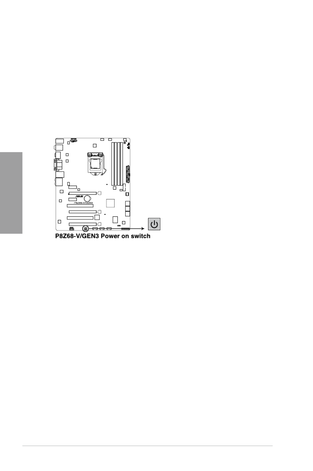
1. Power-on switch
The motherboard comes with a power-on switch that allows you to power up or wake
up the system. The switch also lights up when the system is plugged to a power source
indicating that you should shut down the system and unplug the power cable before
removing or plugging in any motherboard component. The illustration below shows the
location of the onboard power-on switch.

ASUS P8Z68-V/GEN3 2-15
Chapter 2
2. MemOK! switch
Installing DIMMs that are incompatible with the motherboard may cause system
boot failure, and the DRAM_LED near the MemOK! switch lights continuously. Press
and hold the MemOK! switch until the DRAM_LED starts blinking to begin automatic
memory compatibility tuning for successful boot.
• Refer to section 2.2.6 Onboard LEDs
for the exact location of the DRAM_LED.
• The DRAM_LED also lights when the DIMM is not properly installed. Turn off the
system and reinstall the DIMM before using the MemOK! function.
• The MemOK! switch does not function under Windows™ OS environment.
• During the tuning process, the system loads and tests failsafe memory settings. It
takes about 30 seconds for the system to test one set of failsafe settings. If the test
fails, the system reboots and test the next set of failsafe settings. The blinking speed
of the DRAM_LED increases, indicating different test processes.
• Due to memory tuning requirement, the system automatically reboots when each
timing set is tested. If the installed DIMMs still fail to boot after the whole tuning
process, the DRAM_LED lights continuously. Replace the DIMMs with ones
recommended in the Memory QVL (Qualied Vendors Lists) in this user manual or on
the ASUS website at www.asus.com.
• If you turn off the computer and replace DIMMs during the tuning process, the system
continues memory tuning after turning on the computer. To stop memory tuning, turn
off the computer and unplug the power cord for about 5–10 seconds.
• If your system fail to boot due to BIOS overclocking, press the MemOK! switch to boot
and load BIOS default settings. A messgae will appear during POST reminding you
that the BIOS has been restored to its default settings.
• We recommend that you download and update to the latest BIOS version from the
ASUS website at www.asus.com after using the MemOK! function.

2-16 Chapter 2: Hardware information
Chapter 2
3. TPU switch
Turning this switch to
Enable will automatically optimize the system for fast, yet stable
clock speeds.
For ensuring the system performance, turn the switch setting to
Enable when the system is
powered off.
• The TPU LED (O2LED1) near the TPU switch lights when the switch setting is turned
to Enable . Refer to section
2.2.6 Onboard LEDs for the exact location of the TPU
LED.
• If you change the switch setting to
Enable under the OS environment, the TPU
function will be activated after the next system bootup.
• You may use the TurboV and Auto Tuning feature in the TurboV EVO application,
adjust the BIOS setup program, or enable the TPU switch at the same time. However,
the system will use the last setting you have made.

ASUS P8Z68-V/GEN3 2-17
Chapter 2
4. EPU switch
Turning this switch to Enable will automatically detect the current PC loadings and
intelligently moderate the power consumption.
For ensuring the system performance, turn the switch setting to Enable when the system is
powered off.
• The EPU LED (O2LED2) near the EPU switch lights when the switch setting is turned
to Enable . Refer to section 2.2.6 Onboard LEDs for the exact location of the EPU
LED.
• If you change the switch setting to Enable under the OS environment, the EPU
function will be activated after the next system bootup.
• You may change the EPU settings in the software application or BIOS setup program,
and enable the EPU function at the same time. However, the system will use the last
setting you have made.

2-18 Chapter 2: Hardware information
Chapter 2
2.2.6 Onboard LEDs
1. POST State LEDs
The POST State LEDs of CPU, DRAM, VGA card, and HDD indicate key components
status during POST (Power-on Self Test). If an error is found , the LED next to the
error device will continue lighting until the problem is solved. This user-friendly design
provides an intuitional way to locate the root problem within a second.
ASUS P8Z68-V/GEN3 2-19
Chapter 2
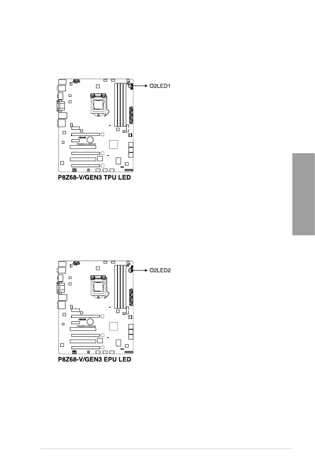
3. EPU LED
The EPU LED lights when the EPU switch is turned to Enable .
2. TPU LED
The TPU LED lights when the TPU switch is turned to Enable .

2-20 Chapter 2: Hardware information
Chapter 2
2.2.7 Jumper
Clear RTC RAM (3-pin CLRTC)
This jumper allows you to clear the Real Time Clock (RTC) RAM in CMOS. You can clear the
CMOS memory of date, time, and system setup parameters by erasing the CMOS RTC RAM
data. The onboard button cell battery powers the RAM data in CMOS, which include system
setup information such as system passwords.
Except when clearing the RTC RAM, never remove the cap on CLRTC jumper default
position. Removing the cap will cause system boot failure!
To erase the RTC RAM:
1. Turn OFF the computer and unplug the power cord.
2. Move the jumper cap from pins 1-2 (default) to pins 2-3. Keep the cap on pins 2-3 for
about 5-10 seconds, then move the cap back to pins 1-2.
3. Plug the power cord and turn ON the computer.
4. Hold down the <Del> key during the boot process and enter BIOS setup to re-enter
data.
• If the steps above do not help, remove the onboard battery and move the jumper again
to clear the CMOS RTC RAM data. After the CMOS clearance, reinstall the battery.
• You do not need to clear the RTC when the system hangs due to overclocking. For
system failure due to overclocking, use the C.P.R. (CPU Parameter Recall) feature.
Shut down and reboot the system so the BIOS can automatically reset parameter
settings to default values.
• Due to the chipset behavior, AC power off is required to enable C.P.R. function. You
must turn off and on the power supply or unplug and plug the power cord before
rebooting the system.

ASUS P8Z68-V/GEN3 2-21
Chapter 2
2.2.8 Internal connectors
1. Intel ® Z68 Serial ATA 6.0 Gb/s connectors (7-pin SATA6G_1/2 [gray])
These connectors connect to Serial ATA 6.0 Gb/s hard disk drives via Serial ATA 6.0
Gb/s signal cables.
If you installed Serial ATA hard disk drives, you can create a RAID 0, 1, 5, and 10
conguration with the Intel ® Rapid Storage Technology through the onboard Intel ® Z68
chipset.
•
These connectors are set to [AHCI Mode] by default. If you intend to create a Serial
ATA RAID set using these connectors, set the SATA Mode item in the BIOS to [RAID
Mode]. Refer to section 3.5.4 SATA Conguration for details.
• Before creating a RAID set, refer to section 4.4 RAID congurations or the manual
bundled in the motherboard support DVD.
•
When using NCQ, set the SATA Mode in the BIOS to [AHCI Mode]. Refer to section
3.5.4 SATA Conguration for details.
•
You must install Windows ®
XP Service Pack 3 or later versions before using Serial
ATA hard disk drives. The Serial ATA RAID feature is available only if you are using
Windows ® XP SP3 or later versions.

2-22 Chapter 2: Hardware information
Chapter 2
2. Intel ® Z68 Serial ATA 3.0 Gb/s connectors (7-pin SATA3G_3–6 [blue])
These connectors connect to Serial ATA 3.0 Gb/s hard disk drives and optical disc
drives via Serial ATA 3.0 Gb/s signal cables.
If you installed Serial ATA hard disk drives, you can create a RAID 0, 1, 5, and 10
conguration with the Intel ® Rapid Storage Technology through the onboard Intel ® Z68
chipset.
•
These connectors are set to [AHCI Mode] by default. If you intend to create a Serial
ATA RAID set using these connectors, set the SATA Mode item in the BIOS to [RAID
Mode]. Refer to section 3.5.4 SATA Conguration for details.
• Before creating a RAID set, refer to section 4.4 RAID congurations or the manual
bundled in the motherboard support DVD.
•
When using NCQ, please check the SATA Mode in the BIOS is [AHCI Mode]. Refer to
section 3.5.4 SATA Conguration
for details.
•
You must install Windows ® XP Service Pack 3 or later versions before using Serial
ATA hard disk drives. The Serial ATA RAID feature is available only if you are using
Windows ® XP SP3 or later versions.

ASUS P8Z68-V/GEN3 2-23
Chapter 2
3. USB 3.0 connector (20-1 pin USB3_34)
These connectors are for the additional USB 3.0 ports, and complies with the USB 3.0
specicaton that supports up to 480 MBps connection speed. If the USB 3.0 front panel
cable is available from your system chassis, with this USB 3.0 connector, you can have
a front panel USB 3.0 solution.
The USB 3.0 module is purchased separately.
2-24 Chapter 2: Hardware information
Chapter 2
You can connect the front panel USB cable to the ASUS Q-Connector (USB, blue) rst, and
then install the Q-Connector (USB) to the USB connector onboard if your chassis supports
front panel USB ports.
Never connect a 1394 cable to the USB connectors. Doing so will damage the motherboard!
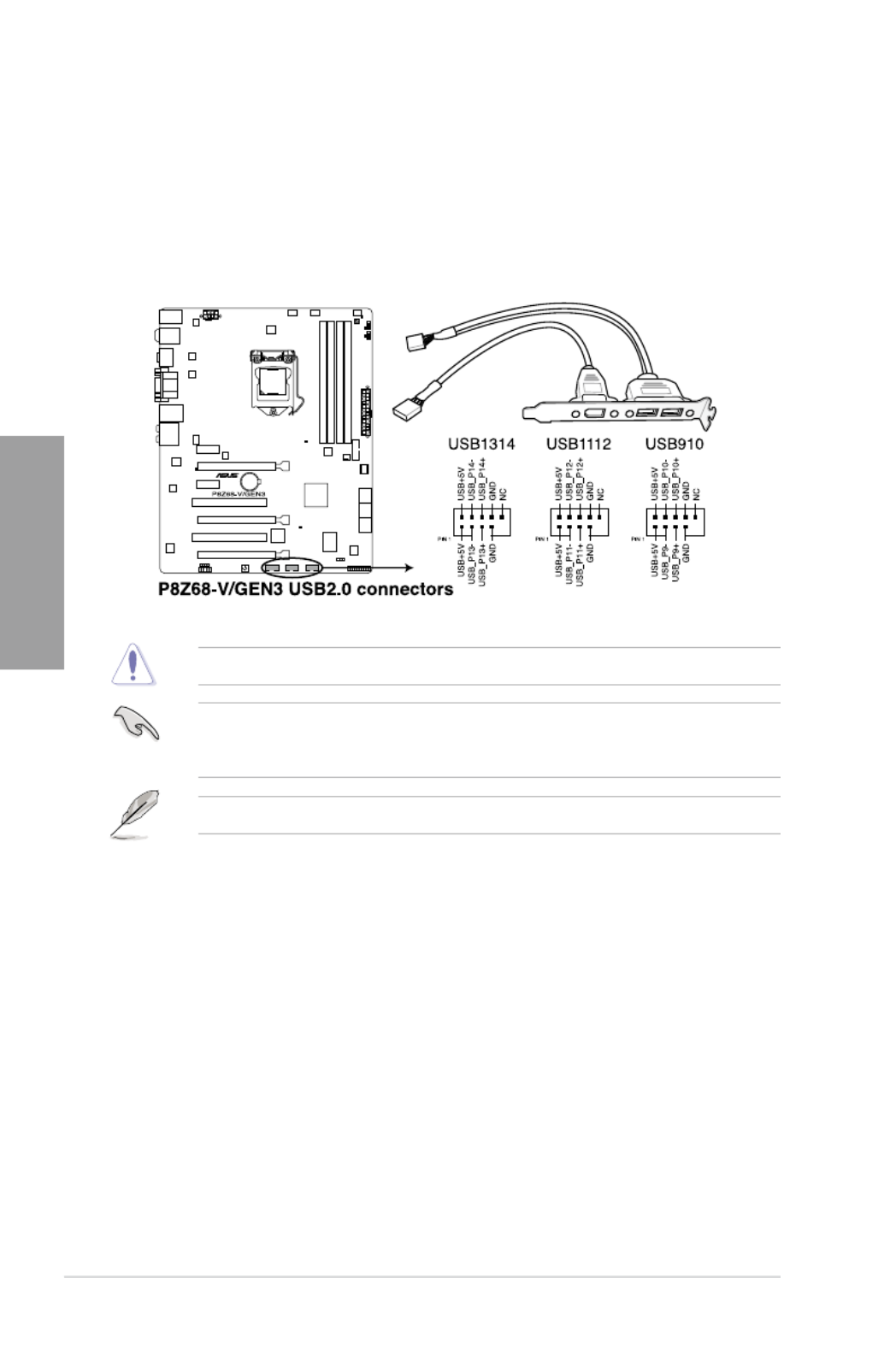
4. USB 2.0 connectors (10-1 pin USB78; USB910; USB1112)
These connectors are for USB 2.0 ports. Connect the USB module cable to any of
these connectors, then install the module to a slot opening at the back of the system
chassis. These USB connectors comply with USB 2.0 specication that supports up to
48 MBps connection speed.
The USB 2.0 module is purchased separately.
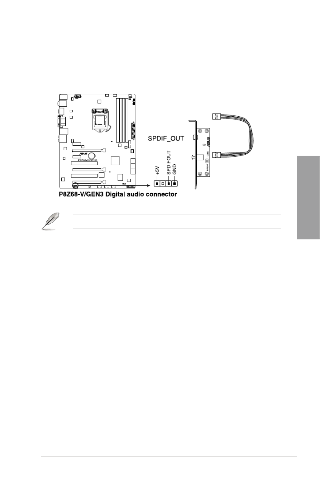
ASUS P8Z68-V/GEN3 2-25
Chapter 2
5. Digital audio connector (4-1 pin SPDIF_OUT)
This connector is for an additional Sony/Philips Digital Interface (S/PDIF) port(s).
Connect the S/PDIF Out module cable to this connector, then install the module to a
slot opening at the back of the system chassis.
The S/PDIF module is purchased separately.

2-26 Chapter 2: Hardware information
Chapter 2
6. CPU, chassis, and power fan connectors
(4-pin CPU_FAN/CPU_FAN_OPT; 4-pin CHA_FAN1; 3-pin CHA_FAN2; 3-pin
PWR_FAN1/2)
Connect the fan cables to the fan connectors on the motherboard, ensuring that the
black wire of each cable matches the ground pin of the connector.
• The CPU_FAN connector supports the CPU fan of maximum 1A (12 W) fan power.
• Only the CPU_FAN, CHA_FAN 1 and CHA_FAN 2 connectors support the ASUS FAN
Xpert feature.
• If you install two VGA cards, we recommend that you plug the rear chassis fan cable
to the motherboard connector labeled CHA_FAN1 or CHA_FAN2 for better thermal
environment.
Do not forget to connect the fan cables to the fan connectors. Insufcient air ow inside the
system may damage the motherboard components. These are not jumpers! Do not place
jumper caps on the fan connectors!

ASUS P8Z68-V/GEN3 2-27
Chapter 2
7. Front panel audio connector (10-1 pin AAFP)
This connector is for a chassis-mounted front panel audio I/O module that supports
either HD Audio or legacy AC`97 audio standard. Connect one end of the front panel
audio I/O module cable to this connector.
• We recommend that you connect a high-denition front panel audio module to this
connector to avail of the motherboard’s high-denition audio capability.
• If you want to connect a high-denition front panel audio module to this connector, set
the Front Panel Type
item in the BIOS setup to [HD]; if you want to connect an AC'97
front panel audio module to this connector, set the item to
[AC97]. By default, this
connector is set to [HD].

2-28 Chapter 2: Hardware information
Chapter 2
• For a fully congured system, we recommend that you use a power supply unit
(PSU) that complies with ATX 12 V Specication 2.0 (or later version) and provides a
minimum power of 350 W.
• Do not forget to connect the 4-pin/8-pin EATX12 V power plug; otherwise, the system
will not boot.
• Use of a PSU with a higher power output is recommended when conguring a system
with more power-consuming devices. The system may become unstable or may not
boot up if the power is inadequate.
• If you are uncertain about the minimum power supply requirement for your system,
refer to the Recommended Power Supply Wattage Calculator at http://support.asus.
com/PowerSupplyCalculator/PSCalculator.aspx?SLanguage=en-us for details.
• If you want to use two or more high-end PCI Express x16 cards, use a PSU with
1000W power or above to ensure the system stability.
8. ATX power connectors (24-pin EATXPWR; 8-pin EATX12V)
These connectors are for ATX power supply plugs. The power supply plugs are
designed to t these connectors in only one orientation. Find the proper orientation and
push down rmly until the connectors completely t.

ASUS P8Z68-V/GEN3 2-29
Chapter 2
• System power LED (2-pin PLED)
This 2-pin connector is for the system power LED. Connect the chassis power LED
cable to this connector. The system power LED lights up when you turn on the system
power, and blinks when the system is in sleep mode.
• Hard disk drive activity LED (2-pin IDE_LED)
This 2-pin connector is for the HDD Activity LED. Connect the HDD Activity LED cable
to this connector. The IDE LED lights up or ashes when data is read from or written to
the HDD.
• System warning speaker (4-pin SPEAKER)
This 4-pin connector is for the chassis-mounted system warning speaker. The speaker
allows you to hear system beeps and warnings.
• ATX power button/soft-off button (2-pin PWRSW)
This connector is for the system power button. Pressing the power button turns the
system on or puts the system in sleep or soft-off mode depending on the BIOS settings.
Pressing the power switch for more than four seconds while the system is ON turns the
system OFF.
• Reset button (2-pin RESET)
This 2-pin connector is for the chassis-mounted reset button for system reboot without
turning off the system power.
9. System panel connector (20-8 pin PANEL)
This connector supports several chassis-mounted functions.

2-30 Chapter 2: Hardware information
Chapter 2
2.3 Building your computer system
2.3.1 Additional tools and components to build a PC system
1 bag of screws Philips (cross) screwdriver
PC chassis Power supply unit
Intel LGA 1155 CPU Intel LGA 1155 compatible CPU Fan
DIMM SATA hard disk drive
SATA optical disc drive (optional) Graphics card (optional)
The tools and components in the table above are not included in the motherboard package.

ASUS P8Z68-V/GEN3 2-31
Chapter 2
A
B
1
2
3
2.3.2 CPU installation
The LGA1156 CPU is incompatible with the LGA1155 socket. DO NOT install a LGA1156
CPU on the LGA1155 socket.

2-32 Chapter 2: Hardware information
Chapter 2
C
B
A
5
6
4
Produktspezifikationen
| Marke: | Asus |
| Kategorie: | Hauptplatine |
| Modell: | P8Z68-V/GEN3 |
Brauchst du Hilfe?
Wenn Sie Hilfe mit Asus P8Z68-V/GEN3 benötigen, stellen Sie unten eine Frage und andere Benutzer werden Ihnen antworten
Bedienungsanleitung Hauptplatine Asus

27 September 2024
19 September 2024
12 September 2024
12 September 2024
12 September 2024
12 September 2024
12 September 2024
12 September 2024
12 September 2024
12 September 2024
Bedienungsanleitung Hauptplatine
- Hauptplatine Gigabyte
- Hauptplatine Sharkoon
- Hauptplatine MSI
- Hauptplatine Supermicro
- Hauptplatine NZXT
- Hauptplatine Asrock
- Hauptplatine ECS
- Hauptplatine EPoX
- Hauptplatine Evga
- Hauptplatine Intel
- Hauptplatine Abit
- Hauptplatine Elitegroup
- Hauptplatine Foxconn
- Hauptplatine Biostar
Neueste Bedienungsanleitung für -Kategorien-

25 November 2024
25 November 2024
25 November 2024
25 November 2024

15 Oktober 2024

7 Oktober 2024
5 Oktober 2024
4 Oktober 2024
4 Oktober 2024
2 Oktober 2024